EP3848068A1 - Selbstausrichtende spritze und spritzenschnittstelle - Google Patents
Selbstausrichtende spritze und spritzenschnittstelle Download PDFInfo
- Publication number
- EP3848068A1 EP3848068A1 EP20209661.6A EP20209661A EP3848068A1 EP 3848068 A1 EP3848068 A1 EP 3848068A1 EP 20209661 A EP20209661 A EP 20209661A EP 3848068 A1 EP3848068 A1 EP 3848068A1
- Authority
- EP
- European Patent Office
- Prior art keywords
- syringe
- locking mechanism
- engagement members
- injector
- deflectable retaining
- Prior art date
- Legal status (The legal status is an assumption and is not a legal conclusion. Google has not performed a legal analysis and makes no representation as to the accuracy of the status listed.)
- Pending
Links
Images


Classifications
-
- A—HUMAN NECESSITIES
- A61—MEDICAL OR VETERINARY SCIENCE; HYGIENE
- A61M—DEVICES FOR INTRODUCING MEDIA INTO, OR ONTO, THE BODY; DEVICES FOR TRANSDUCING BODY MEDIA OR FOR TAKING MEDIA FROM THE BODY; DEVICES FOR PRODUCING OR ENDING SLEEP OR STUPOR
- A61M5/00—Devices for bringing media into the body in a subcutaneous, intra-vascular or intramuscular way; Accessories therefor, e.g. filling or cleaning devices, arm-rests
- A61M5/14—Infusion devices, e.g. infusing by gravity; Blood infusion; Accessories therefor
- A61M5/142—Pressure infusion, e.g. using pumps
- A61M5/145—Pressure infusion, e.g. using pumps using pressurised reservoirs, e.g. pressurised by means of pistons
- A61M5/1452—Pressure infusion, e.g. using pumps using pressurised reservoirs, e.g. pressurised by means of pistons pressurised by means of pistons
- A61M5/14546—Front-loading type injectors
-
- A—HUMAN NECESSITIES
- A61—MEDICAL OR VETERINARY SCIENCE; HYGIENE
- A61M—DEVICES FOR INTRODUCING MEDIA INTO, OR ONTO, THE BODY; DEVICES FOR TRANSDUCING BODY MEDIA OR FOR TAKING MEDIA FROM THE BODY; DEVICES FOR PRODUCING OR ENDING SLEEP OR STUPOR
- A61M5/00—Devices for bringing media into the body in a subcutaneous, intra-vascular or intramuscular way; Accessories therefor, e.g. filling or cleaning devices, arm-rests
- A61M5/007—Devices for bringing media into the body in a subcutaneous, intra-vascular or intramuscular way; Accessories therefor, e.g. filling or cleaning devices, arm-rests for contrast media
-
- A—HUMAN NECESSITIES
- A61—MEDICAL OR VETERINARY SCIENCE; HYGIENE
- A61M—DEVICES FOR INTRODUCING MEDIA INTO, OR ONTO, THE BODY; DEVICES FOR TRANSDUCING BODY MEDIA OR FOR TAKING MEDIA FROM THE BODY; DEVICES FOR PRODUCING OR ENDING SLEEP OR STUPOR
- A61M5/00—Devices for bringing media into the body in a subcutaneous, intra-vascular or intramuscular way; Accessories therefor, e.g. filling or cleaning devices, arm-rests
- A61M5/14—Infusion devices, e.g. infusing by gravity; Blood infusion; Accessories therefor
- A61M5/1407—Infusion of two or more substances
- A61M5/1408—Infusion of two or more substances in parallel, e.g. manifolds, sequencing valves
-
- A—HUMAN NECESSITIES
- A61—MEDICAL OR VETERINARY SCIENCE; HYGIENE
- A61M—DEVICES FOR INTRODUCING MEDIA INTO, OR ONTO, THE BODY; DEVICES FOR TRANSDUCING BODY MEDIA OR FOR TAKING MEDIA FROM THE BODY; DEVICES FOR PRODUCING OR ENDING SLEEP OR STUPOR
- A61M5/00—Devices for bringing media into the body in a subcutaneous, intra-vascular or intramuscular way; Accessories therefor, e.g. filling or cleaning devices, arm-rests
- A61M5/14—Infusion devices, e.g. infusing by gravity; Blood infusion; Accessories therefor
- A61M5/142—Pressure infusion, e.g. using pumps
- A61M5/145—Pressure infusion, e.g. using pumps using pressurised reservoirs, e.g. pressurised by means of pistons
- A61M5/1452—Pressure infusion, e.g. using pumps using pressurised reservoirs, e.g. pressurised by means of pistons pressurised by means of pistons
- A61M5/14566—Pressure infusion, e.g. using pumps using pressurised reservoirs, e.g. pressurised by means of pistons pressurised by means of pistons with a replaceable reservoir for receiving a piston rod of the pump
-
- A—HUMAN NECESSITIES
- A61—MEDICAL OR VETERINARY SCIENCE; HYGIENE
- A61M—DEVICES FOR INTRODUCING MEDIA INTO, OR ONTO, THE BODY; DEVICES FOR TRANSDUCING BODY MEDIA OR FOR TAKING MEDIA FROM THE BODY; DEVICES FOR PRODUCING OR ENDING SLEEP OR STUPOR
- A61M5/00—Devices for bringing media into the body in a subcutaneous, intra-vascular or intramuscular way; Accessories therefor, e.g. filling or cleaning devices, arm-rests
- A61M5/178—Syringes
- A61M5/31—Details
- A61M5/315—Pistons; Piston-rods; Guiding, blocking or restricting the movement of the rod or piston; Appliances on the rod for facilitating dosing ; Dosing mechanisms
- A61M5/31533—Dosing mechanisms, i.e. setting a dose
- A61M5/31545—Setting modes for dosing
-
- A—HUMAN NECESSITIES
- A61—MEDICAL OR VETERINARY SCIENCE; HYGIENE
- A61M—DEVICES FOR INTRODUCING MEDIA INTO, OR ONTO, THE BODY; DEVICES FOR TRANSDUCING BODY MEDIA OR FOR TAKING MEDIA FROM THE BODY; DEVICES FOR PRODUCING OR ENDING SLEEP OR STUPOR
- A61M5/00—Devices for bringing media into the body in a subcutaneous, intra-vascular or intramuscular way; Accessories therefor, e.g. filling or cleaning devices, arm-rests
- A61M5/14—Infusion devices, e.g. infusing by gravity; Blood infusion; Accessories therefor
- A61M5/142—Pressure infusion, e.g. using pumps
- A61M5/145—Pressure infusion, e.g. using pumps using pressurised reservoirs, e.g. pressurised by means of pistons
- A61M5/1452—Pressure infusion, e.g. using pumps using pressurised reservoirs, e.g. pressurised by means of pistons pressurised by means of pistons
- A61M5/14546—Front-loading type injectors
- A61M2005/14553—Front-loading type injectors comprising a pressure jacket
-
- A—HUMAN NECESSITIES
- A61—MEDICAL OR VETERINARY SCIENCE; HYGIENE
- A61M—DEVICES FOR INTRODUCING MEDIA INTO, OR ONTO, THE BODY; DEVICES FOR TRANSDUCING BODY MEDIA OR FOR TAKING MEDIA FROM THE BODY; DEVICES FOR PRODUCING OR ENDING SLEEP OR STUPOR
- A61M5/00—Devices for bringing media into the body in a subcutaneous, intra-vascular or intramuscular way; Accessories therefor, e.g. filling or cleaning devices, arm-rests
- A61M5/14—Infusion devices, e.g. infusing by gravity; Blood infusion; Accessories therefor
- A61M5/142—Pressure infusion, e.g. using pumps
- A61M5/145—Pressure infusion, e.g. using pumps using pressurised reservoirs, e.g. pressurised by means of pistons
- A61M5/1452—Pressure infusion, e.g. using pumps using pressurised reservoirs, e.g. pressurised by means of pistons pressurised by means of pistons
- A61M2005/14573—Pressure infusion, e.g. using pumps using pressurised reservoirs, e.g. pressurised by means of pistons pressurised by means of pistons with a replaceable reservoir for quick connection/disconnection with a driving system
-
- A—HUMAN NECESSITIES
- A61—MEDICAL OR VETERINARY SCIENCE; HYGIENE
- A61M—DEVICES FOR INTRODUCING MEDIA INTO, OR ONTO, THE BODY; DEVICES FOR TRANSDUCING BODY MEDIA OR FOR TAKING MEDIA FROM THE BODY; DEVICES FOR PRODUCING OR ENDING SLEEP OR STUPOR
- A61M2205/00—General characteristics of the apparatus
- A61M2205/19—Constructional features of carpules, syringes or blisters
-
- A—HUMAN NECESSITIES
- A61—MEDICAL OR VETERINARY SCIENCE; HYGIENE
- A61M—DEVICES FOR INTRODUCING MEDIA INTO, OR ONTO, THE BODY; DEVICES FOR TRANSDUCING BODY MEDIA OR FOR TAKING MEDIA FROM THE BODY; DEVICES FOR PRODUCING OR ENDING SLEEP OR STUPOR
- A61M2205/00—General characteristics of the apparatus
- A61M2205/60—General characteristics of the apparatus with identification means
- A61M2205/6063—Optical identification systems
Definitions
- the present disclosure relates generally to a system including a self-orienting, front-loading syringe for use with a fluid injector and, further, to a connection interface for securing the syringe to the fluid injector and to a method for loading and removal of the syringe to and from the fluid injector.
- a medical practitioner such as a physician injects a patient with one or more medical fluids.
- medical fluids such as a contrast solution (often referred to simply as "contrast"), a flushing agent, such as saline, and other medical fluids
- CT computed tomography
- MRI magnetic resonance imaging
- PET positron emission tomography
- these fluid injectors are designed to deliver a preset amount of fluid at a preset pressure and/or flow rate.
- the medical practitioner places a catheter or a needle connected to tubing, or other fluid delivery connection into a vein or artery of the patient.
- the catheter or the tubing is connected to either a manual or to an automatic fluid injection mechanism.
- Automatic fluid injection mechanisms typically include at least one syringe connected to at least one fluid injector having, for example, at least one powered linear piston.
- the at least one syringe includes, for example, a source of contrast and/or a source of flushing fluid.
- the medical practitioner enters settings into an electronic control system of the fluid injector for a fixed volume of contrast and/or saline and a fixed rate of injection for each.
- the injected contrast and/or saline are delivered to a patient's vasculature through the catheter or needle inserted into the patient's body, such as the patient's arm or groin area.
- a dose of contrast is referred to as a bolus.
- a conventional imaging technique such as angiography imaging or scanning, computed tomography (CT), ultrasound, magnetic resonance imaging (MRI), positron emission tomography (PET), and other molecular imaging procedures.
- CT computed tomography
- MRI magnetic resonance imaging
- PET positron emission tomography
- the presence of the contrast becomes clearly visible against the background of the surrounding tissue.
- the syringe having a retention feature is inserted into a syringe port on the fluid injector by aligning the syringe with a corresponding locking feature provided on the fluid injector. It is often necessary for the medical practitioner to manually align the retention feature of the syringe with the corresponding locking feature on the fluid injector before the syringe can be loaded onto the injector. In some cases, there are only one or two alignments, such as shown in United States Patent No. 6,336,913 .
- the operator must pull on the syringe at the same time while rotating the syringe.
- Such syringe injector features require additional time and effort to load/remove the syringe from the injector, resulting in increased time for a medical injection procedure.
- a syringe may include a barrel having a distal end, a proximal end, and a substantially circumferential sidewall extending between the distal end and the proximal end along a longitudinal axis.
- At least one engagement member may protrude from a terminal portion at the proximal end of the sidewall in a proximal direction along the longitudinal axis.
- the at least one engagement member may taper axially and/or circumferentially in a direction from the distal end toward the proximal end.
- the at least one engagement member may be configured for engagement with a locking mechanism of a fluid injector to releasably position the syringe within a syringe port of the fluid injector.
- a taper of the at least one engagement member may be configured to rotationally guide the syringe into alignment with the locking mechanism and axially eject the syringe upon rotation of the syringe.
- a plurality of engagement members may extend about at least a portion of a circumference of the terminal portion.
- the plurality of engagement members may be spaced apart evenly or unevenly about the circumference of the terminal portion.
- the at least one engagement member may have a wave form or a substantially sinusoidal form.
- the at least one engagement member may have a pointed proximal end with at least one tapered surface that extends from the pointed proximal end in a distal direction along the longitudinal axis to the terminal portion of the sidewall.
- the pointed proximal end of the at least one engagement member may have a sharp or rounded point.
- the at least one tapered surface may be angled relative to a direction of the longitudinal axis.
- the at least one tapered surface may be linear, curvilinear, continuous, discontinuous, or planar.
- an encoding device may be provided on at least a portion of the syringe, such as on at least one of the at least one engagement member.
- the at least one engagement member may be monolithically formed with the terminal portion of the sidewall.
- the at least one engagement member may have a circular, triangular, or a polygonal shape. In other embodiments, the at least one engagement member may be separable from the terminal portion of the sidewall.
- a retention flange may protrude radially outwardly from the outer surface of the sidewall relative to the longitudinal axis and distally of the at least one engagement member for engaging with the locking mechanism of the fluid injector to releasably lock the syringe with the syringe port of the fluid injector.
- the retention flange may extend around at least a portion of the outer surface of the sidewall.
- the retention flange may interact with at least one deflectable retaining element to retain the syringe within the locking mechanism.
- the retention flange may have a longitudinal stop surface for limiting a length of a longitudinal insertion of the syringe into the locking mechanism.
- a plunger may be slidably disposed within the barrel of the syringe and movable between the proximal end and the distal end.
- the syringe may further include a drip flange distal to the retention flange for preventing medical fluid from dripping from the distal end of the syringe into a syringe port of a medical injector and fouling the interior workings of the medical injector.
- a fluid injection apparatus may include at least one syringe having a barrel with a distal end, a proximal end, and a substantially circumferential sidewall extending between the distal end and the proximal end along a longitudinal axis.
- the barrel may have at least one engagement member protruding from a terminal portion of the proximal end of the sidewall in a proximal direction along the longitudinal axis.
- the at least one engagement member may taper axially and/or circumferentially in a direction from the distal end toward the proximal end.
- the fluid injection apparatus may further include an injector having an injector housing defining at least one syringe port for receiving the proximal end of the at least one syringe.
- a locking mechanism may be associated with the at least one syringe port for releasably securing the at least one syringe within the at least one syringe port.
- the locking mechanism may be configured for engaging the at least one engagement member of the syringe to releasably position the at least one syringe.
- a taper of the at least one engagement member may be configured to rotationally guide the syringe into self-alignment with the locking mechanism and axially eject the syringe upon rotation of the syringe within the locking mechanism. In certain embodiments, rotation of the syringe within the locking mechanism disengages the retention flange from the at least one deflectable retaining element prior to axially ejecting the syringe.
- the locking mechanism may include a housing having a central opening configured to receive the proximal end of the at least one syringe.
- a guide ring may be fixed relative to the housing with a central axis of the guide ring in coaxial alignment with a central axis of the housing.
- the guide ring may have at least one recess extending from an inner circumference of the guide ring to an outer circumference of the guide ring.
- At least one deflectable retaining element may be configured to be movably received within the at least one recess of the guide ring.
- a lock/release ring may be configured for engagement with the at least one engagement member when the at least one syringe is inserted into the at least one syringe port.
- the lock/release ring may be rotatable relative to the housing with a rotation of the at least one syringe about the longitudinal axis.
- At least one elastically resilient member may be connected at one end to at least a portion of the at least one deflectable retaining element to urge the at least one deflectable retaining element in a radially inward direction to disengage a retention flange on the at least one syringe.
- the at least one deflectable retaining element may have a locking lip that is angled relative to the longitudinal axis such that movement of the at least one syringe in a proximal direction causes movement of the at least one deflectable retaining element in a radially outward direction.
- the lock/release ring may include one or more syringe engagement members that have a complementary shape to receive the at least one engagement member.
- the lock/release ring may include at least one guide slot disposed on a top surface to guide a movement of the at least one deflectable retaining element.
- the at least one guide slot may include at least one guide track.
- the at least one deflectable retaining element may engage the at least one guide track at a first end when the at least one deflectable retaining element is in a first radial position, and may engage the at least one guide track at a second end when the at least one deflectable retaining element is in a second radial position that is different than the first radial position.
- Lateral edges of the at least one recess may define a travel path for guiding movement of the at least one deflectable retaining element.
- At least a portion of a top surface of the guide ring may define a stop surface that limits a movement of the at least one syringe in a proximal direction when the at least one syringe is inserted into the at least one syringe port.
- a syringe may include a barrel having a distal end, a proximal end, and a substantially circumferential sidewall extending between the distal end and the proximal end along a longitudinal axis.
- At least one engagement member may protrude from a terminal portion of the proximal end of the sidewall in a proximal direction along the longitudinal axis.
- the at least one engagement member may taper axially and/or circumferentially in a direction from the distal end toward the proximal end.
- a retention flange may protrude radially outwardly from the outer surface of the sidewall relative to the longitudinal axis and distally of the at least one engagement member.
- the at least one engagement member may be configured for engagement with a locking mechanism of a fluid injector to releasably position the syringe within the syringe port of the fluid injector.
- a taper of the at least one engagement member may be configured to rotationally guide the syringe into self-alignment with the locking mechanism and axially eject the syringe upon rotation of the syringe.
- rotation of the syringe within the locking mechanism disengages the retention flange from the at least one deflectable retaining element prior to axially ejecting the syringe.
- the present disclosure provides a syringe comprising:
- the present disclosure provides a syringe according to any of the aspects described herein, wherein a plurality of engagement members extend about at least a portion of a circumference of the terminal portion.
- the present disclosure provides a syringe according to any of the aspects described herein, wherein the plurality of engagement members are spaced apart evenly about the circumference of the terminal portion.
- the present disclosure provides a syringe according to any of the aspects described herein, wherein the at least one engagement member has a wave form or sinusoidal form.
- the present disclosure provides a syringe according to any of the aspects described herein, wherein the at least one engagement member has a pointed proximal end with at least one tapered surface that extends from the pointed proximal end in a distal direction along the longitudinal axis to the terminal portion of the sidewall.
- the present disclosure provides a syringe according to any of the aspects described herein, wherein the pointed proximal end of the at least one engagement member has a sharp or rounded point.
- the present disclosure provides a syringe according to any of the aspects described herein, wherein the at least one tapered surface is angled relative to a direction of the longitudinal axis.
- the present disclosure provides a syringe according to any of the aspects described herein, wherein the at least one tapered surface is linear or curvilinear.
- the present disclosure provides a syringe according to any of the aspects described herein, wherein the at least one tapered surface is continuous or discontinuous.
- the present disclosure provides a syringe according to any of the aspects described herein, wherein the at least one tapered surface is planar.
- the present disclosure provides a syringe according to any of the aspects described herein, further comprising at least one encoding device on at least a portion of the syringe.
- the present disclosure provides a syringe according to any of the aspects described herein, wherein the at least one encoding device is on at least one of the at least one engagement member.
- the present disclosure provides a syringe according to any of the aspects described herein, wherein the at least one engagement member is monolithically formed with the terminal portion of the sidewall.
- the present disclosure provides a syringe according to any of the aspects described herein, wherein the at least one engagement member is separable from the terminal portion of the sidewall.
- the present disclosure provides a syringe according to any of the aspects described herein, further comprising a flange protruding radially outwardly from the outer surface of the sidewall relative to the longitudinal axis and distally of the at least one engagement member for engaging with the locking mechanism of the fluid injector to releasably lock the syringe with the syringe port of the fluid injector.
- the present disclosure provides a syringe according to any of the aspects described herein, wherein the flange extends around at least a portion of the outer surface of the sidewall.
- the present disclosure provides a syringe according to any of the aspects described herein, wherein the flange has a longitudinal stop surface for limiting a length of a longitudinal insertion of the syringe into the locking mechanism.
- the present disclosure provides a syringe according to any of the aspects described herein, wherein the at least one engagement member has a circular, triangular, or a polygonal shape.
- the present disclosure provides a syringe according to any of the aspects described herein, further comprising a plunger slidably disposed within the barrel and movable between the proximal end and the distal end.
- the present disclosure provides a fluid injection apparatus, comprising:
- the present disclosure provides a fluid injection apparatus according to any of the aspects described herein, wherein the locking mechanism further comprises:
- the present disclosure provides a fluid injection apparatus according to any of the aspects described herein, further comprising at least one elastically resilient member connected at one end to at least a portion of the at least one deflectable retaining element to urge the at least one deflectable retaining element in a radially inward direction.
- the present disclosure provides a fluid injection apparatus according to any of the aspects described herein, wherein the at least one deflectable retaining element comprises a locking lip that is angled relative to the longitudinal axis such that movement of the at least one syringe in a proximal direction causes movement of the at least one deflectable retaining element in a radially outward direction.
- the present disclosure provides a fluid injection apparatus according to any of the aspects described herein, wherein the lock/release ring comprises one or more syringe engagement members that have a complementary shape to receive the at least one engagement member.
- the present disclosure provides a fluid injection apparatus according to any of the aspects described herein, wherein the lock/release ring comprises at least one guide slot disposed on a top surface to guide a movement of the at least one deflectable retaining element.
- the present disclosure provides a fluid injection apparatus according to any of the aspects described herein, wherein the at least one guide slot comprises at least one guide track.
- the present disclosure provides a fluid injection apparatus according to any of the aspects described herein, wherein the at least one deflectable retaining element engages the at least one guide track at a first end when the at least one deflectable retaining element is in a first radial position, and wherein the at least one deflectable retaining element engages the at least one guide track at a second end when the at least one deflectable retaining element is in a second radial position that is different than the first radial position.
- the present disclosure provides a fluid injection apparatus according to any of the aspects described herein, wherein lateral edges of the at least one recess define a travel path for guiding movement of the at least one deflectable retaining element.
- the present disclosure provides a fluid injection apparatus according to any of the aspects described herein, wherein at least a portion of a top surface of the guide ring defines a stop surface that limits a movement of the at least one syringe in a proximal direction when the at least one syringe is inserted into the at least one syringe port.
- the present disclosure provides a syringe comprising:
- proximal refers to a portion of a syringe nearest to an injector when a syringe is oriented for connecting to an injector.
- distal refers to a portion of a syringe farthest away from an injector when a syringe is oriented for connecting to an injector.
- radial refers to a direction in a cross-sectional plane normal to a longitudinal axis of a syringe extending between proximal and distal ends.
- circumferential refers to a direction around an inner or outer surface of a sidewall of a syringe.
- axial refers to a direction along a longitudinal axis of a syringe extending between proximal and distal ends.
- self-orienting means that a syringe orients itself to the correct orientation within a syringe port during insertion without effort by a technician.
- axial taper means an angle of inclination of at least one virtual or real surface on a syringe in a cylindrical plan projection view in a direction from a distal end toward a proximal end of a syringe. It is also to be understood that specific devices and processes illustrated in the attached drawings, and described in the following specification, are simply exemplary embodiments of the disclosure. Hence, specific dimensions and other physical characteristics related to the embodiments ( i.e. , aspects, variants, variations, etc.) disclosed herein are not to be considered as limiting.
- connection interface between at least one syringe and a fluid injector.
- a fluid injector 10 such as an automated or powered fluid injector, is illustrated, which is adapted to interface with and actuate one or more syringes 12, which may be filled with a medical fluid F, such as contrast media, saline solution, or any desired medical fluid.
- the injector 10 may be used during a medical procedure to inject the medical fluid into the body of a patient by driving a plunger 26 of the syringe 12 with a piston element.
- the injector 10 may be a multi-syringe injector, wherein several syringes 12 may be oriented in a side-by-side or other relationship and are separately actuated by plungers 26 on respective linear actuators or piston elements associated with the injector 10.
- the injector 10 may be configured to independently deliver one or more fluids from the at least one syringes 12.
- the injector 10 may be enclosed within a housing 14 formed from a suitable structural material, such as plastic or metal.
- the housing 14 may be of various shapes and sizes depending on the desired application.
- the injector 10 may be a freestanding structure configured to be placed on the floor or may be a smaller design for placement on a suitable table or support frame.
- the injector 10 includes at least one syringe port 16 for connecting the at least one syringe 12 to respective piston elements.
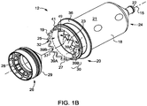
- the syringe 12 includes at least one engagement member configured for releasably self-orienting the syringe 12 within the syringe port 16 of the injector 10.
- the at least one engagement member is configured to operatively engage a locking mechanism provided in the syringe port 16 of the injector 10 to facilitate loading or removal of the syringe 12 to and from the injector 10, including ejecting the syringe 12 from the syringe port 16, as will be described herein.
- the at least one engagement member and the locking mechanism together define a connection interface for reversibly connecting the at least one syringe 12 to the injector 10.
- a fluid path set 17 may be fluidly connected with at least one of the at least one syringe 12 for delivering medical fluid F from the at least one syringe 12 to a catheter (not shown), needle, or other fluid delivery connection inserted into a patient at a vascular access site.
- Fluid flow from the at least one syringe 12 may be regulated by a fluid control module (not shown).
- the fluid control module operates various pistons, valves and flow regulating structures to regulate the delivery of the medical fluid, such as saline solution and contrast to the patient based on user selected injection parameters, such as injection flow rate, duration, total injection volume, and ratio of contrast media and saline.
- a suitable front-loading fluid injector that may be modified for use with at least one syringe and at least one syringe interface for self-oriented loading and releasable retaining of the at least one syringe with the fluid injector described herein is disclosed in United States Patent No. 5,383,858 to Reilly et al. which is incorporated by reference in its entirety.
- Other relevant multi-fluid delivery systems that may be so modified are found in United States Patent No. 7,553,294 to Lazzaro et al. ; United States Patent No. 7,666,169 to Cowan et al. ; International Patent Application No. PCT/US2012/037491 , (published as WO 2012/155035 ); and United States Patent Application Publication No. 2014/0027009 to Riley et al. ; all of which are assigned to the assignee of the present application, and the disclosures of which are incorporated herein by reference.
- the syringe 12 generally has a substantially cylindrical syringe barrel 18 formed from glass, metal, or a suitable medical-grade plastic.
- the barrel 18 has a proximal end 20 and a distal end 24, with a substantially circumferential sidewall 19 extending therebetween along a length of a longitudinal axis 15 extending through a center of the barrel 18.
- the barrel 18 may be made from a transparent or translucent material, and may include at least one fluid verification member 11 for verifying a presence of the fluid F within the syringe barrel 18 (shown in FIG. 1A ).
- a nozzle 22 for connecting to a fluid path 17 extends from the distal end 24 of the barrel 18.
- the barrel 18 has an outer surface 21 and an inner surface 23 that defines an interior volume 25 configured for receiving the medical fluid therein.
- the proximal end 20 of the barrel 18 may be sealed with the plunger 26 that is slidable through the barrel 18.
- the plunger 26 forms a liquid-tight seal against the inner surface of sidewall 19 of the barrel 18 as it is reversibly advanced therethrough.
- the plunger 26 may have a rigid inner element 28 configured for engagement with the piston of the injector 10.
- the plunger 26 may further include an elastomeric cover 29 disposed over at least a portion of the rigid inner element 28.
- the elastomeric cover 29 is configured to engage the inner surface 23 of the barrel 18 and provide a liquid-tight seal against the sidewall 19 of the barrel 18 as it is reversibly advanced therethrough.
- the proximal end 20 of the syringe 12 is sized and adapted to be inserted in the at least one syringe port 16 of the injector 10 (shown in FIG. 1A ).
- the proximal end 20 of the syringe 12 defines an insertion portion 30 that is configured to be removably inserted into the syringe port 16 of the injector 10 while the remaining portion of the syringe 12 remains outside of the syringe port 16.
- the proximal end 20 of the syringe 12 includes at least one engagement member 32 adapted to form a locking engagement with a corresponding locking mechanism in the syringe port 16 of the injector 10 for releasably retaining the syringe 12 in the syringe port 16.
- the combination of the syringe 12 having the one or more engagement members 32 with a retention flange 41 and the locking mechanism 35 (shown in FIG. 2B ) of the injector 10 defines a connection interface for loading and unloading of the syringe 12 to and from the injector 10.
- a drip flange 36 may extend radially outward from the outer surface 21 of the syringe barrel 18 relative to the longitudinal axis 15.
- the drip flange 36 may extend around at least a portion of the outer circumference of the barrel 18.
- the drip flange 36 is positioned distally along the longitudinal axis 15 relative to the one or more engagement members 32 and distal to the retention flange 41.
- the drip flange 36 may be configured to prevent fluid that drips from the nozzle 22 from entering the syringe port 16 on the injector 10. In this manner, the drip flange 36 helps reduce the amount of fluid that may enter the syringe port 16 and jam or interfere with the connection interface 100 or otherwise foul the mechanics or electronics of the injector 10.
- the drip flange 36 may define an insertion stop surface that delimits how far the insertion portion 30 of the syringe 12 may be inserted into the syringe port 16 and/or locking mechanism of the injector 10.
- the drip flange 36 may be formed integrally with the barrel 18 or it may be affixed or otherwise secured to the outer surface 21 of the barrel 18 using, for example, a frictional fit and/or an adhesive, welding, or by molding. In other embodiments, the drip flange 36 may be formed on the outer surface 21 of the barrel 18 by etching, laser cutting, or machining.
- the insertion stop surface may be defined by the retention flange 41 positioned closer to the proximal end 20 of the barrel 18 relative to the drip flange 36, if present.
- the retention flange 41 may extend radially outward from the outer surface 21 of the syringe barrel 18 relative to the longitudinal axis 15.
- the retention flange 41 may extend around at least a portion of the outer circumference of the barrel 18 and may be a single continuous flange or one or more discontinuous or intermittent segments.
- the retention flange 41 is positioned distally along the longitudinal axis 15 relative to the engagement member 32.
- the retention flange 41 may be formed integrally with the barrel 18 or it may be affixed or otherwise secured to the outer surface 21 of the barrel 18 using, for example, a frictional fit and/or an adhesive, welding, or by molding. In other embodiments, the retention flange 41 may be formed on the outer surface 21 of the barrel 18 by etching, laser cutting, or machining. The retention flange 41 may be anywhere along the length of the barrel 18 in a distal direction from the one or more engagement members 32. In some embodiments, the retention flange 41 may be formed directly on or adjacent the one or more engagement members 32.
- the retention flange 41 may also be formed by increasing the thickness of the sidewall 19 while maintaining a constant inner diameter of the barrel 18 or by increasing the inner diameter of the barrel 18 and maintaining, decreasing, or increasing the thickness of the sidewall 19.
- the distal surface of the retention flange 41 forms a retention surface 41R (shown in FIG. 2A ) which interfaces with one or more retention surfaces 78R (shown in FIG. 2B ) on one or more retaining elements 78 of syringe port 16.
- At least a portion of the retention flange 41 for example a proximal surface of retention flange 41, may be tapered or beveled in a radial direction toward or away from the longitudinal axis 15.
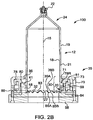
- connection interface 100 for loading and removing/ejecting the at least one syringe 12 from the at least one syringe port 16 of the injector 10 (shown in FIG. 1 ) is shown in accordance with one embodiment.
- the syringe 12 and the injector 10 include the connection interface 100 having at least one engagement member 32 provided on the syringe 12 and a corresponding locking mechanism 35 provided on the syringe port 16 of the injector 10 (shown in FIG. 1 ).
- the at least one engagement member 32 is provided on the proximal end 20 of the syringe barrel 18.
- the at least one engagement member 32 may protrude axially in a proximal direction from the terminal end 27 of the syringe barrel 18.
- the at least one engagement member 32 may be formed integrally and monolithically with the barrel 18 or it may be affixed or otherwise secured to the terminal end 27 of the barrel 18 using, for example, a frictional fit and/or an adhesive, or by welding.
- the at least one engagement member 32 may be formed on the terminal end 27 of the barrel 18 by etching, laser cutting, machining, or molding.
- the one or more engagement members 32 cooperate with at least a portion of the locking mechanism to self-orient the syringe 12 relative to the syringe port 16 such that the syringe 12 may be releasably locked with the syringe port 16 without physical aligning of the syringe or other effort by the user or technician to orient the syringe 12 with syringe port 16 and/or locking mechanism 35.
- the at least one engagement member 32 is formed as one or more projections that protrude axially in a proximal direction from the terminal end 27 of the syringe barrel 18 indicated by a dashed line in FIGS. 1B and 2A -2B.
- the at least one engagement member 32 may have the same radial thickness as the sidewall 19 of the syringe barrel 18 such that the at least one engagement member 32 is substantially continuous with the outer surface 21 and the inner surface 23 (shown in FIG. 1B ) of the barrel 18.
- the at least one engagement member 32 may protrude radially outward or radially inward relative to the outer surface 21 of the barrel 18.
- the at least one engagement member 32 may protrude radially outward or radially inward relative to the inner surface 23 of the barrel 18.
- the at least one engagement members 32 may be located within the interior of sidewall 19, for example, such that terminal ends of the inner surface 23 and outer surface 21 are substantially even with the proximal end of the at least one engagement member 32.
- a plurality of engagement members 32 may be arranged around a circumference of the barrel 18 in a waveform or sinusoidal form, as detailed herein. In embodiments where more than two engagement members 32 are provided, the engagement member 32 may be evenly spaced about an outer circumference of the barrel 18.
- each engagement member 32 is separated 60 degrees apart from adjacent engagement members 32.
- each engagement member 32 is separated 360/x degrees apart from adjacent engagement members 32, where x is an integer from 1 to 360.
- the at least one engagement members 32 may have unequal angular spacing therebetween about the outer circumference of the barrel 18.
- one or more engagement members 32 may subtend an angle A (shown in FIG. 1B ), which may be more than 60 degrees or less than 60 degrees of the circumference of the barrel 18.
- the spacing and arrangement of the various engagement members 32 may be used to encode information regarding the syringe and/or the syringe content, such as manufacturer, lot number, date of manufacture, volume, pressure minimum/maximum, compatibility with various medical fluids, etc.
- each of the engagement members 32 may protrude at an equal distance from the terminal end 27 of the syringe barrel 18 in a proximal direction. In other embodiments, one or more engagement members 32 may be longer or shorter than the remaining engagement members 32.
- Each engagement member 32 is substantially rigid and free from deflecting in a radial or circumferential direction during insertion and removal of the syringe 12 to and from the syringe port 16.
- Each engagement member 32 may be continuous and uninterrupted, or it may be comprised of a plurality of separate elements that together define the engagement member 32.
- each of the engagement members 32 may have a substantially pointed proximal end 37 with a pair of tapered surfaces 39A-39B that extend from the proximal end 37 of engagement member 32 in a distal direction along the longitudinal axis 15 toward the terminal end 27 of the syringe 12.
- the proximal end 37 may have a sharp or rounded point.
- At least one of the tapered surfaces 39A-39B may be angled axially and/or circumferentially relative to a direction of the longitudinal axis 15 at an angle B (shown in FIG. 1B ).
- the axial/circumferential tapering of the at least one tapered surfaces 39A-39B relative to the longitudinal axis 15 may be defined as an angle of inclination of at least one of the tapered surfaces 39A-39B in a cylindrical plan projection view in a direction from the distal end 24 toward the proximal end 20 of the syringe barrel 18.
- the tapered surfaces 39A-39B may be angled at a same or different angle relative to the longitudinal axis 15.
- the tapered surfaces 39A-39B may be linear, curved, or a combination thereof.
- the profile of one of the tapered surfaces 39A-39B may the same or different from the other of the tapered surfaces 39A-39B.
- one of the tapered surfaces 39A-39B may be angled relative to the direction of the longitudinal axis 15, while the other of the tapered surfaces 39A-39B may be parallel with the direction of the longitudinal axis 15.
- the tapered surface 39A on one engagement member 32 may transition to the tapered surface 39B of each adjacent engagement member 32.
- FIGS. 2A-2B illustrate one non-limiting embodiment of the at least one engagement member 32
- various other shapes are also contemplated (see, for example FIG. 4A-4Q for other non-limiting embodiments).
- the at least one engagement member 32 may have a generally circular, triangular, square, rectangular, or any other polygonal shape.
- the at least one engagement member 32 in combination with the retention flange 41, is configured for forming a self-orienting locking engagement with a corresponding locking mechanism 35 in the syringe port 16 of the injector 10 for releasably retaining the syringe 12 in the syringe port 16, as described herein.
- the number of engagement members 32 used may be varied while remaining within the scope of the present disclosure.
- the syringe 12 illustrated in FIG. 1B it is contemplated that only one engagement member 32 is provided at the terminal end 27 of the syringe 12.
- embodiments of the syringe 12 may have at least two engagement members 32.
- the engagement members 32 may be located diametrically opposite one another.
- the engagement members 32 are provided adjacent to each other.
- the engagement members 32 may be appropriately sized and optionally may be of different circumferential dimension.
- suitable shapes for the at least one engagement member 32 are described herein with reference to FIGS. 4A-4Q .
- the syringe port 16 of the injector 10 has a locking mechanism 35 configured to operatively engage the at least one engagement member 32 and the retention flange 41 of the syringe 12.
- the locking mechanism 35 includes a housing 70 with a central opening 71 configured to receive the proximal end 20 of the syringe 12.
- the housing 70 may be formed as part of the housing 14 of the injector 10 (shown in FIG. 1A ) or may be attachable to the housing 14 to convert an existing injector to include the presently described locking mechanism 35.
- a guide ring 48 may be secured relative to the housing 70 such the guide ring 48 cannot rotate or move longitudinally relative to the housing 70.
- the guide ring 48 has a body 72 having one or more tabs 74 (shown in FIG. 2A ) extending radially outward from an outer circumference of the body 72.
- the body 72 of the guide ring 48 may have a continuous annular shape, or it may be formed from two or more discrete segments.
- the one or more tabs 74 engage corresponding one or more grooves 76 (shown in FIG. 2A ) on an inner sidewall 73 of the housing 70 to prevent rotation/longitudinal movement of guide ring 48.
- the guide ring 48 may be secured to the housing 70 by other mechanical fastening arrangements, such as a clip, fastener, or a snap fit arrangement.
- the guide ring 48 may be welded, glued, or molded with the housing 70. When installed on the housing 70 , a central axis of the guide ring 48 is coaxial with a central axis of the housing 70.
- the guide ring 48 has one or more first recesses 60 that are configured to slidably receive a corresponding one or more deflectable retaining elements 78.
- the one or more first recesses 60 may be evenly spaced about the body 72 of the guide ring 48.
- the one or more first recesses 60 extend from an inner circumference of the guide ring 48 to an outer circumference thereof.
- each first recess 60 may be separated 90 degrees apart from the first recesses 60 adjacent on either side.
- the one or more first recesses 60 may be unevenly spaced about the body 72 of the guide ring 48.
- first recesses 60 on the guide ring 48 may correspond to the number of deflectable retaining elements 78.
- First recesses 60 may include a groove or pin on the bottom surface to interface with a pin or groove, respectively, on the bottom surface of deflectable retaining elements 78 to guide movement of the deflectable retaining elements 78.
- the lateral edges of each first recess 60 define a radial travel path for guiding the movement of the deflectable retaining elements 78 in a radial direction as the insertion portion 30 of the syringe 12 is inserted into and out of the guide ring 48.
- At least a portion of a top surface of the guide ring 48 may define a stop surface 59 that limits a movement of the syringe 12 in the proximal direction when the syringe 12 is inserted into the locking mechanism 35.
- the retention flange 41 of the syringe 12 engages the stop surface 59 to limit the movement of the syringe 12 in the proximal direction.
- the locking mechanism 35 further includes one or more deflectable retaining elements 78 configured for sliding in a radial direction relative to the guide ring 48.
- each of the one or more deflectable retaining elements 78 is radially slidable relative to the guide ring 48 and the housing 70, which are both fixed relative to each other.
- At least one first elastically resilient member 102 (shown in FIG. 2A ), such as a spring, is connected at one end to at least a portion of the one or more deflectable retaining elements 78 and at the other end to at least a portion of the housing 70.
- the at least one first elastically resilient member 102 urges the one or more deflectable retaining elements 78 to a first position (see FIG. 2B ) where a locking lip 80 on the at least one deflectable retaining element 78 is positioned over the stop surface 59 of the guide ring 48 to define a retaining gap 81 (see FIG. 2B ).
- the retention flange 41 of the syringe 12 engages the locking lip 80 of the at least one deflectable retaining element 78 to deflect the deflectable retaining element 78 radially outward and allow the syringe 12 to be inserted into the locking mechanism 35.
- the locking lip 80 may be radially angled relative to the longitudinal axis 15 such that movement of the syringe 12 in the proximal direction results in a force having a radially directed component that urges the at least one deflectable retaining element 78 radially outward relative to the syringe 12.
- the proximal surface of the retention flange 41 may be radially angled or beveled relative to the longitudinal axis 15 such that movement of the syringe 12 in the proximal direction results in a force having a radially directed component that urges the at least one deflectable retaining element 78 radially outward relative to the syringe 12.
- the at least one deflectable retaining element 78 is restored to its initial, first position under the urging of the at least one first elastically resilient member 102.
- the one or more engagement members 32 on the syringe 12 engage a lock/release ring 84, and, when rotated, cause the one or more deflectable retaining elements 78 to move to a second or open position and allowing ejection of the syringe 12 from the locking mechanism 35, as described herein.
- the locking mechanism 35 may further include the lock/release ring 84 having a generally annular shape.
- the lock/release ring 84 is configured for engaging one or more of the at least one engagement member 32 to control selective positioning of the syringe 12 within the syringe port 16 to allow for selective locking engagement of one or more deflectable retaining elements 78 with the retention flange 41 of the syringe 12.
- the lock/release ring 84 is rotatable relative to the housing 70 with the rotation of the syringe 12 about its longitudinal axis 15 by engagement of the at least one engagement member 32 with at least one syringe engagement member 83.
- the lock/release ring 84 has one or more syringe engagement members 83 extending around an inner circumference of the lock/release ring 84.
- the one or more syringe engagement members 83 have a complementary shape to that of one or more of the at least one engagement members 32 on the syringe 12.
- the one or more syringe engagement members 83 are shaped to correspond to the shape of the at least one engagement members 32 at the terminal end 27 of the syringe 12.
- the one or more one or more syringe engagement members 83 may have a waveform or sinusoidal shape.
- the one or more syringe engagement members 83 have interacting surfaces 85A, 85B along which the tapered surfaces 39A-39B can slide as the syringe 12 is inserted into or withdrawn from the syringe port 16.
- the interacting surfaces 85A, 85B are tapered to a sharp or rounded point in a distal direction facing the syringe 12. At least one of the interacting surfaces 85A, 85B may be angled axially relative to a direction of the longitudinal axis 15.
- the axial tapering of the at least one interacting surface 85A, 85B relative to the longitudinal axis 15 may be defined as an angle of inclination of the interacting surface 85A, 85B in a cylindrical plan projection view in a direction toward the proximal end 20 of the syringe 12 when the syringe 12 is inserted into the syringe port 16.
- the interacting surfaces 85A, 85B may be angled at a same or different angle relative to the longitudinal axis 15.
- the interacting surfaces 85A, 85B may be linear, curved, stepped but defining a substantially linear/curved surface, or a combination thereof.
- the profile of one of the interacting surfaces 85A, 85B may the same or different from the other of the interacting surfaces 85A, 85B.
- one of the interacting surface 85A, 85B may be angled relative to the direction of the longitudinal axis 15, while the other of the interacting surface 85A, 85B may be parallel with the direction of the longitudinal axis 15.
- the one or more syringe engagement members 83 may be shaped to have a corresponding or complimentary shape and angular spacing such that each of the engagement members 32 engages a respective syringe engagement member 83.
- the at least one engagement members 32 may have a multiple of engagement members 32 relative to the number of the one or more syringe engagement members 83. In a first position, such as when the syringe 12 is locked within the locking mechanism 35, each engagement member 32 is aligned with the corresponding syringe engagement member 83. In a second position, such as when the syringe 12 is to be removed from the locking mechanism 35, each engagement member 32 is rotationally moved out of alignment with the corresponding syringe engagement member 83.
- the lock/release ring 84 further includes a guide slot 86 to guide the movement of each of the deflectable retaining elements 78.
- Each guide slot 86 is disposed on an outer periphery of a top surface 88 of the lock/release ring 84.
- Each guide slot 86 has a guide track 90 on which the corresponding deflectable retaining element 78 is guided between the first position, where the syringe 12 is locked within the locking mechanism 35, and a second position, where the syringe 12 is unlocked from the locking mechanism 35.
- each deflectable retaining element 78 engages the guide track 90, such as by a pin or other engaging member protruding proximally from the bottom of the deflectable retaining element 78.
- each deflectable retaining element 78 engages the guide track 90 at a first end 92 such that each deflectable retaining element 78 is at its most radially-inward position.
- the retention flange 41 of the syringe 12 is retained by the locking lip 80 of the one or more deflectable retaining elements 78 such that the syringe 12 cannot be removed from the locking mechanism 35 without rotating the syringe 12 relative to its longitudinal axis 15 and engaging the release mechanism.
- each deflectable retaining element 78 is guided radially outward along the guide track 90 toward a second end 94, where each deflectable retaining element 78 is at its most radially-outward position.
- the syringe 12 is removed from the locking mechanism 35 by ejecting or urging the syringe 12 in a distal direction such that the retention flange 41 clears the locking lip 80 of each deflectable retaining element 78.
- the lock/release ring 84 is concurrently rotated to the first position under a restoring action of a second elastically resilient member 96 that may be secured to a base 98 of the housing 70.
- rotation of the lock/release ring 84 back to the first position under the restoring action of a second elastically resilient member 96 may provide a lateral force to the syringe 12 to eject or urge the syringe 12 out of the syringe port 16.
- the longitudinal axis 15 of the syringe 12 is roughly aligned with the longitudinal axis of the syringe port 16.
- the syringe 12 can be inserted into a top portion of the central opening 71 without rotationally orienting the syringe 12 about the longitudinal axis 15 relative to the syringe port 16.
- the insertion portion 30 of the syringe 12 is inserted into the opening 71 of the syringe port 16.
- the syringe retention flange 41 is urged in a proximal direction into contact with the locking lip 80 of the at least one deflectable retaining element 78 to deflect it radially outward and allow the syringe 12 to be inserted into the housing 70.
- Continued proximal movement of the syringe 12 relative the syringe port 16 causes the one or more deflectable retaining elements 78 to be deflected radially outward within the first recesses 60 to a second position in which the size of the central opening is increased to allow the retention flange 41 to pass through.
- the syringe 12 is advanced proximally into the syringe port 16 such that the one or more tapered surfaces 39A, 39B on each engagement member 32 come into contact with the corresponding interacting surfaces 85A, 85B to rotationally self-orient the syringe 12 such that the peaks of the engagement members 32 are received in the valleys of the syringe engagement member 83 on the syringe port 16 and/or until the retention flange 41 engages the stop surface 59 on the guide ring 48.
- the one or more deflectable retaining elements 78 are then urged radially from the second position to the first position where the locking lip 80 of the one or more deflectable retaining elements 78 may be positioned over the retention flange 41 between the stop surface 59 and a bottom face of the locking lip 80.
- the drip flange 36 acts as a retention flange 41
- the one or more deflectable retaining elements 78 may be positioned over the retention flange 41 to retain the drip flange 36 between the stop surface 59 and a bottom face of the locking lip 80.
- An audible and/or tactile feedback may be provided by this action to indicate to the user that the syringe 12 is locked within the syringe port 16.
- the syringe 12 may be rotated about its longitudinal axis 15, for example in a clockwise or counterclockwise direction. Rotation of the syringe 12 causes the at least one engagement members 32 to move against the one or more syringe engagement members 83, thus rotating lock/release ring 84 to move the one or more deflectable retaining elements 78 radially to the second position to release the retention flange 41 from locking lip 80.
- each deflectable retaining element 78 is guided radially outward along the guide track 90 toward the second end 94, where each deflectable retaining element 78 is at its most radially-outward position.
- the syringe barrel 18 and the retaining ring 41 are urged distally against the one or more deflectable retaining elements 78 which further urges the one or more deflectable retaining elements 78 radially outward from a first position to a second position.
- the syringe 12 may be ejected, urged, or popped out of the syringe port 16 when the locking lip 80 of the one or more deflectable retaining elements 78 clears the retention flange 41 of the syringe 12 without any applied distal force from the user.
- the lock/release ring 84 is rotated to the first position under a restoring action of the second elastically resilient member 96 such that the one or more deflectable retaining elements 78 are returned to their first, initial position and the locking mechanism 35 is ready for insertion of a new syringe 12.
- the retention surfaces of the syringe 12 and the syringe port 16 that cooperate to retain the syringe 12 in the syringe port 16 once it is engaged are one or more surfaces of the retention flange 41 on the syringe 12 and the one or more retention surfaces of the deflectable retaining elements 78 on the syringe port 16.
- the syringe 12 is initially generally axially aligned and inserted into the opening 71 of the syringe port 16.
- the guiding surfaces of the syringe 12 and syringe port 16 that cooperate to self-orient or automatically force the rotational movement to self-orient the syringe 12 and the syringe port 16 for installation are the one or more surfaces 39A-39B of the engagement members 32 on the syringe 12 and the one or more tapered guiding surfaces 85A-85B of syringe engagement member 83 of the syringe port 16.
- the opening surfaces of the syringe 12 and syringe port 16 that cooperate to push open the syringe port 16 for the installation of the syringe 12 are the one or more bottom surfaces of the retention flange 41 on the syringe 12 and one or more of tapered surfaces of the locking lip 80 on the syringe port 16.
- the tightening surfaces of the syringe 12 and syringe port 16 that cooperate to take up the mechanical slack or tolerance may include one or more surfaces on the drip flange 36 on the syringe 12 which push against the outside housing or a seal of the syringe port 16 and urge the retention flange 41 against the locking lip 80 on the syringe port 16.
- the tightening force to urge the syringe 12 forward may be provided by a resilient member, such as a second elastically resilient member 96 that rotationally urges lock/release ring 84 causing a distal force from interaction of one or more surfaces 39A-39B of the engagement members 32 on the syringe 12 and the one or more tapered guiding surfaces 85A-85B of syringe engagement member 83 or a third resilient member (not shown) that urges the lock/release ring 84 in a distal direction, and when cooperating with a syringe 12 of sufficient length, urges the retention flange 41 against the locking lip 80.
- a resilient member such as a second elastically resilient member 96 that rotationally urges lock/release ring 84 causing a distal force from interaction of one or more surfaces 39A-39B of the engagement members 32 on the syringe 12 and the one or more tapered guiding surfaces 85A-85B of syringe engagement member 83 or a third resilient
- the detachment surfaces of the syringe 12 and syringe port 16 that cooperate to disengage or remove the syringe 12 from the syringe port 16 are surfaces of the engagement members 32 of the syringe 12 and surfaces of the syringe engagement member 83 of the syringe port 16.
- the ejection surfaces of the syringe 12 and syringe port 16 that cooperate to create a distally directed force to urge ejection of the syringe 12 from the syringe port 16 are the one or more tapered surfaces 39A, 39B on the engagement members 32 of the syringe 16 and one or more tapered guiding surfaces 85A-85B of the syringe engagement member 83 on the syringe port 16.
- the rotational stop surfaces of the syringe 12 and syringe port 16 that cooperate to prevent rotation as a luer connector is screwed onto the syringe 12 are one or more tapered surfaces 39A, 39B on the engagement members 32 of the syringe 12 and one or more tapered guiding surfaces 85A-85B of the syringe engagement member 83 on the syringe port 16, as well as any frictional force between the one or more surfaces of the retention flange 41 of the syringe 12 and one or more retention surfaces of the deflectable retaining elements 78 of the syringe port 16 and/or between the bottom surface of drip flange 36 and the outside housing or a seal of the syringe port 16.
- FIGS. 3A-3D show cylindrical plan projection views of various embodiments of the at least one engagement members 32 at the proximal end 20 of the syringe 12 and the syringe engagement member 83 of a corresponding syringe port 16 for receiving the proximal end 20 of the syringe 12.
- a cylindrical plan projection view of the interface between the at least one engagement members 32 at the proximal end 20 of the syringe 12 and the syringe engagement member 83 of the lock/release ring 84 is shown in a rotationally aligned orientation for mating the syringe 12 to the syringe port 16.
- the at least one engagement members 32 on the syringe 12 and the corresponding syringe engagement members 83 on the syringe port 16 are configured as generally sinusoidal projections the proximal end 20 of the syringe 12 having alternating peaks and valleys on the syringe 12 and on the lock/release ring 84.
- the engagement members 32 on the syringe 12 project axially away from the terminal end 27 of the syringe 12.
- the downward or distal force in a direction of arrow A causes a sliding interaction of the tapered surfaces 39A-39B on the syringe 12 with the corresponding tapered guiding surfaces 85A-85B on the syringe engagement members 83.
- Such sliding interaction causes the syringe 12 to rotate and self-orient into the correct rotational position for alignment with the corresponding tapered guiding surfaces 85A-85B on the syringe engagement members 83 and correctly oriented installation of the syringe 12 into the syringe port 16.
- FIG. 3B is another cylindrical plan projection view of an alternative embodiment of the syringe 12.
- the engagement members 32 extend only partially through the thickness of sidewall 19 of the syringe barrel 18.
- the engagement members 32 may be positioned on the outside surface 21 of the syringe barrel 18.
- the proximal end 37 of the engagement members 32 may terminate at the terminal end 27 of the syringe barrel 18.
- the proximal end 37 may extend in a proximal direction relative to the terminal end 27 of the syringe barrel 19, as illustrated, for example, in FIG. 3A . In this manner, the syringe barrel 18 can be made stronger for a more rigid axial alignment.
- FIG. 3C is another cylindrical plan projection view of an alternative embodiment in which the engagement members 32 extend only partially through the thickness of sidewall 19 of the syringe barrel 18 and are positioned on the inside surface of the syringe barrel 12. A corresponding complementary arrangement of the syringe engagement members 83 is present on the lock/release ring 84.
- the inside material of the lock/release ring 84 may strengthen the proximal end 20 of the syringe barrel 18 and allow use in higher pressure injections.
- the engagement members 32 may extend through at least a portion of the sidewall 19 of the syringe barrel 18 from the outer surface 21 or the inner surface 23 of the syringe 12.
- the engagement members 32 are formed by creating voids or pockets of appropriate cross sections within the sidewall 19 of the syringe barrel 18. The voids or pockets may be configured to interact with complementary syringe engagement members 83 present on the lock/release ring 84.
- FIG. 3D is a cylindrical plan projection view of an embodiment of an adapter 12B for use with an alternative syringe 12A that cannot itself directly interface with the syringe port 16 and/or locking mechanism 35 described herein.
- the adapter 12B may be configured, for example as a ring, arc, or other shape, that removably or non-removably attaches to at least a portion of the terminal end 27A of the alternative syringe 12A or that may be inserted into locking mechanism 35 in syringe port 16 to adapt locking mechanism 35 to interact with the alternative syringe 12A.
- the adapter 12B may have one or more engagement members 32B similar to the at least one engagement members 32 of syringe 12 described herein.
- Each engagement member 32B may be configured for interacting with a corresponding syringe engagement member 83 of the syringe port 16.
- the distal side of the adapter 12B may have features or projections that mate with corresponding features or projections of the syringe 12A.
- the adapter 12B may have locking members 87B that are configured to be received within a corresponding locking member 87A on the syringe 12A, or other locking features that allow syringe 12A to mate with adapter 12B and be retained within syringe port 16 and/or locking mechanism 35.
- FIGS. 4A-4Q show portions of the cylindrical plan projection views of various embodiments of a portion of the at least one engagement members 32 on the syringe 12 and the corresponding embodiments of syringe engagement members 83 on the lock/release ring 84 in syringe port 16.
- FIGS. 4A-4Q display shapes of alternative embodiments of engagement members 32 (labeled as 32A-32Q ) and/or syringe engagement members 83 (labeled as 83A-83Q ) suitable for use with embodiments of the syringe 12 and/or lock/release ring 84 in syringe port 16.
- FIG. 4A shows segments of engagement members 32 and 83 of the embodiment described herein with reference to FIG. 3A in a cylindrical plan projection view.
- FIG. 4B illustrates with dotted lines the approximate surfaces of engagement members 32B on the syringe 12 and the corresponding syringe engagement members 83B on the syringe port 16 for various embodiments.
- FIG. 4C shows an embodiment in which a valley YYC of syringe engagement members 83C is extended compared to the surface of engagement member 32C
- FIG. 4D shows an embodiment in which the surfaces of the syringe engagement member 83D include one or more linear segments to define a valley YYD for receiving engagement member 32D.
- FIG. 4E illustrates an embodiment in which at least a portion of a valley YYE of 83E has a substantially rectangular profile, for example, to reduce interference from any debris or other external material while still being capable of interacting with engagement member 34E.
- FIG. 4F illustrates an embodiment in which the syringe engagement member 83F has a flat bottom surface 83FA with one or more distal projections 83FB which may selectively contact the engagement members 32F on the syringe 12.
- the bottom segment of engagement members 32F of syringe 12 touch valley sections YYF of the syringe engagement member 83F to allow some rotational slop, gap, or tolerance before rotation of the syringe 12 will cause contact between tapered surface 32F and one or more distal projection 83FB and a corresponding rotation of the lock/release ring 84F.
- the bottom segment of the engagement members 32G do not touch valley sections YYG of the syringe engagement member 83G. Rather, the engagement members 32G engage at least a portion of the projections 83GB in an operation similar to that in FIG. 4F.
- FIG. 4H shows an embodiment in which both the engagement members 32H and the syringe engagement members 83H have at least one segmented linear surface, with the peaks of the syringe engagement members 83H fitting into but preferably not fully filling the valleys of engagement members 32H on the syringe 12.
- FIG. 4I shows another embodiment in which both the engagement members 321 and syringe engagement members 831 are too wide to fit completely into the respective valleys to ensure that the interaction takes place between the angled surfaces of the respective members.
- FIG. 4J shows engagement members 32J having a plurality of separate segments of varying length in the longitudinal direction 15, with the tips or ends of the segments defining the generally sinusoidal profile or other profile described herein required to fit within syringe engagement members 83J.
- FIG. 4K shows engagement members 32K having a plurality of separate segments of a common length such that a portion of the segments may flex radially but not circumferentially when the syringe 12 is inserted into the syringe port 16.
- syringe engagement members 83 may include springloaded balls or fingers which can travel circumferentially and group together to match the contours of engagement members 32 on the syringe 12 and transmit rotational forces for activation of the disengagement action.
- FIG. 4L shows an embodiment with engagement members 32L having a rod-shaped structure including a projection substantially parallel with the longitudinal axis 15 configured for interacting with the syringe engagement member 83L.
- the engagement members 32L have a virtual tapering surfaces 39A-39B extending from a proximal tip of each engagement member 32L in a distal direction toward the terminal end 27 of the syringe barrel 18 (shown in FIG. 1B ).
- FIG. 4M shows an embodiment of the engagement members 32M having a rod-shaped structure with a projection that is angled such that it tapers relative to the longitudinal axis 15 (shown in FIG. 2B ).
- the engagement members 32M may be sufficiently rigid to interact with the syringe engagement member 83M.
- Other embodiments of engagement member 32 may include a strengthening support between the syringe terminal end 27 and a middle portion of the projection.
- the engagement members 32M may flex when rotated for disengagement and thus provide and added spring force during the ejection of the syringe 12 from the syringe port 16.
- FIG. 4N shows an embodiment in which the engagement members 32N and syringe engagement members 83N define a saw tooth pattern having substantially linear tapered surfaces meeting to form a substantially angled peak.
- the engagement members 32N may have equal or unequal peak to peak height or taper angles relative to the syringe engagement members 83N or vice versa.
- FIG. 4O illustrates an embodiment in which the frequency of the engagement members 32O on the syringe 12 is greater than, for example twice, that of the syringe engagement members 83O on the lock/release ring 84 in syringe port 16.
- the frequency of the engagement members 32O on the syringe 12 may be an integer multiple to the frequency of the syringe engagement members 83O on the syringe port 16. In other embodiments, the frequency of the engagement members 32O on the syringe 12 may be less than the frequency of the syringe engagement members 83O on the syringe port 16, for example an integer ratio of the frequency.
- FIG. 4P illustrates an embodiment in which one or more of the syringe engagement members 83P is absent. Although not shown, one or more of the engagement members 32P on the syringe 12 could also be absent. Alternatively, one or more of the engagement members 32P may be absent. FIG.
- FIG. 4Q illustrates an embodiment in which the engagement members 32Q are rounded at their proximal point and angular at their most distal point, with complementary syringe engagement member 83Q having a substantially pointed peak. While various non-embodiments for shapes of the at least one engagement members 32 have been represented in FIG. 4A-4Q it is to be understood that such shapes may be used on the syringe engagement members 83 or on both the engagement members 32 and syringe engagement members 83 according to other embodiments of the present disclosure. Further, combinations of the various engagement member shapes may be used on syringe 12, lock/release ring 84 or both.
- engagement members 32 on a syringe 12 may include various combinations of the various embodiments of the engagement members represented in FIGS. 4A-4Q and equivalents, as described herein.
- syringe engagement members 83 on a lock/release ring 84 may include various combinations of the various embodiments of the syringe engagement members represented in FIGS. 4A-4Q and equivalents, as described herein.
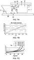
- FIG. 5A is an illustration of a generalized free body diagram of forces present between the tapered surface 39A-39B on the at least one engagement member 32 and the tapered guiding surface 85A-85B on the at least one syringe engagement member 83 during insertion of the syringe 12 into the syringe port 16.
- the at least one engagement member 32 on the syringe 12 interacts with the at least one syringe engagement member 83 on the syringe port 16 due to a distally directed force P provided by the user's hand.
- the syringe 12 may be made from a polyethylene terephthalate (PET) material, while the lock/release ring 84 may be made from a polyoxymethylene (POM) material, such as DELRINTM.
- PET polyethylene terephthalate
- POM polyoxymethylene
- the coefficient of friction ⁇ of DELRINTM on another DELRINTM surface is approximately 0.4. The coefficients of friction of various other surfaces can be measured and used in the calculations as appropriate.
- a practical limit of the angle A to enable reasonable insertion behavior is approximately 60-65 degrees measured relative to a direction of the longitudinal axis 15 of the syringe 12.
- Other practical limits of angle A may be determined for other coefficients of friction to determine the optimal angle range for tapered surfaces 39A-39B and 85A-85B of the at least one engagement members 32 and the at least one syringe engagement members 83, respectively.
- an angle less than 50-55° may be used.
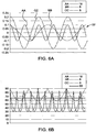
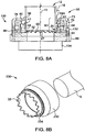
- FIG. 6A shows an overlay of three different sinusoidal designs for the at least one engagement members 32 of syringe 12.
- Pattern AA has a peak to peak height of 0.2 inch and a repetition of 16 cycles around a 1.9 inch diameter syringe. The barrel wall thickness is relatively small compared to the syringe diameter.
- Pattern BB has a peak to peak height of 0.2 inch, and a repetition of 6 cycles around the 1.9 inch diameter syringe.
- Pattern CC has a peak to peak height of 0.4 inch with a repetition of 8 cycles around a 1.9 inch diameter syringe.
- FIG. 6B shows the angular orientation relative to the longitudinal axis 15 (shown in FIG.
- FIG. 7A is an illustration of a generalized free body diagram of forces between the tapered surface 39A-39B on the at least one engagement member 32 and the tapered guiding surface 85A-85B on the at least one syringe engagement member 83 present during release ejection of the syringe 12 into the syringe port 16.
- the forces on the syringe 12 are the normal force N1 and frictional force F1 of the engagement member 32 against the engagement member 83, the normal force N2 and frictional force F2 of the deflectable retaining elements 78 on the retention flange 41 as well as the rotational force T applied by the user to rotate the syringe and any force D urging the syringe proximally provided by the drip flange 36, for example.
- the syringe engagement member 83 there has a normal force N3 and frictional force F3 as it slides over base 98 and the restoring force S from the second elastically resilient members 96. As shown in FIG.
- FIG. 7B shows that the angle A is needed for slip at the interface between engagement member 32 and the syringe engagement member 83.
- the minimum angle is approximately 20 degrees.
- FIG. 7C shows a ratio of the rotational force T to rotate the syringe 12 as the restoring force S of the second elastically resilient member 96 increases. The ratio is relatively constant as the angle increases, but the ratio increases dramatically at higher angles. In some examples, an angle of at least 30 degrees and less than approximately 60 degrees may be used.
- the presence or absence of one or more of the at least one engagement members 32 around the circumference of the syringe barrel 18 may be used to convey or encode information about the syringe 12 or the syringe contents (for example with prefilled syringes).
- such presence or absence of one or more of the at least one engagement members 32 at specific sites around the circumference of the syringe 12 can be sensed by various electronic means, for example, optical sensors, mechanical switches, capacitive sensors, and other means within the syringe port 16 of injector 10.
- a single code can be indicative of the absence of engagement member 32, the absence of two or more engagement members 32 may provide multiple codes, for example for different spaces between the engagement members 32.
- a coupling 130 including a mounting member therefor, can be fabricated to be separate from and attachable to the syringe barrel 18.
- the coupling 130 can, for example, be configured to accept the syringe 12 having at least one engagement member 32 described herein and to adapt the syringe 12 for use with a fluid injector having a syringe port with a locking mechanism not configured to receive the at least one engagement member 32.
- the coupling 130 can adapt the syringe 12 for use with the fluid injector described in United States Patent No. 5,383,858 or United States Patent No. 6,652,489 , or any other fluid injector.
- the coupling 130 is releasably connectable to the injector. In other embodiments, the coupling 130 may be inserted into and retained in a locking mechanism of the fluid injector. The coupling 130 may also be releasably connected or attached to the syringe 12 independently of the attachment of the coupling to the injector.
- the coupling 130 has a first portion 132 configured for receiving the syringe 12 having at least one engagement member 32 according to an embodiment described herein and a second portion 134 configured for loading into an injector having a syringe port not configured to receive the syringe 12 having at least one engagement member 32 according to an embodiment described herein.
- the first portion 132 may be directly connected and monolithically formed with the second portion 134.
- the first portion 132 may be releasably connected to the second portion 134 such that various second portions (shown in FIGS. 9A-9B ) may be used with the first portion 132.
- the first portion 132 has a locking mechanism 35 described herein.
- the first portion 132 of the coupling 130 may be configured for releasably receiving the syringe 12 having a corresponding at least one engagement member 32, as described herein.
- the second portion 134 of the coupling 130 may have a connection interface configured for connecting with an injector that would otherwise not be capable of receiving the syringe 12 having at least one engagement member 32 described herein.
- FIG. 9A shows the second portion 134 configured for use with an engagement mechanism of the injector described in United States Patent No. 5,383,858
- FIG. 9B shows the second portion 134 configured for use with an engagement mechanism of the injector described in United States Patent No. 6,652,489 .
- the second portion 134 may be configured to interface with various other injectors not expressly described herein, based on the configuration of the engagement mechanism on the proximal end of the syringe.
- the coupling 130 may have a separate mechanism for engaging and disengaging the coupling 130 to and from a locking mechanism of the injector.
- an adapter 230 may be configured to receive a syringe S not having one or more engagement members 32 described herein for removably inserting into an injector having the locking mechanism 35 in accordance with one of the embodiments described herein.
- the adapter 230 may be configured for connecting to a syringe S for subsequent installation on an injector.
- the adapter 230 may be connected to the non-compatible syringe S releasably or permanently.
- Such an adapter 230 may have a connection interface having at least one engagement member 32 in accordance with embodiments described herein.
- the adapter 230 may be configured for being releasably connectable with an injector having a locking mechanism 35 described herein.
- the adapter 230 and the syringe S may be connected prior to connecting to the injector, or the adapter 230 may be connected to the injector before the syringe S is connected to the adapter 230.
- the adapter 230 and syringe S may be removed from the injector after use, with the adapter 230 being disposed of with the syringe S, or being removed from the used syringe S and saved for subsequent use with a different syringe S.
- a first portion 232 of the adapter 230 may be configured for permanently or releasably receiving the syringe S which is not compatible for use with any of the locking mechanisms 35 described herein.
- the syringe S may be the syringe described in United States Patent No. 5,383,858 or United States Patent No. 6,652,489 , or any other syringe type.
- the adapter 230 allows the non-compatible syringe S to engage and be retained by the locking mechanism 35 described herein.
- the adapter 230 may have a separate mechanism for engaging and disengaging the syringe S while the adapter 230 remains connected to the locking mechanism 35 of the injector 10.
- the first portion 232 may also be a cradle or sleeve to hold or retain other syringes S, for example hand held syringes or syringes having different retention mechanisms or features and allowing them to engage and be retained by locking mechanisms 35.
- a second portion 234 of the adapter 230 may have at least one engagement member 32 in accordance with embodiments described herein. In some embodiments, the at least one engagement member 32 may have the configuration described herein with reference to FIGS. 1B-4Q .
- the second portion 234 of the adapter 230 may be configured for being releasably connectable with an injector having a locking mechanism 35 described herein.
- the adapter 230 may be configured for connecting a pressure jacket (not shown) to the injector for use in injection procedures requiring high pressure.
- the adapter 230 having the pressure jacket may be configured for being releasably connectable with an injector.
- Such an adapter 230 may have a connection interface having at least one engagement member 32 in accordance with embodiments described herein or alternatively have a connection interface that allows non-compatible syringes to be used with the injector.
- the adapter 230 may be configured for being releasably, permanently, or semi-permanently connectable with an injector having a locking mechanism 35 described herein and allowing syringes S having alternate retaining mechanisms to be used with the injector. Once connected with the injector, a syringe S may be loaded into the adapter 230 or the pressure jacket attached thereto and be retained therein at its proximal or distal end.
- an adapter 230 may be configured for connecting a syringe having some but not all of the features necessary for subsequent installation into an injector 10 described herein, as described herein with reference to FIG. 3D .
- the adapter 230 allows a syringe which could not by itself mate or function fully with injector port 16 to mate and at least perform the retention function with the locking mechanism 35.
- the syringe and the adapter may be released from the syringe port.
- to the adapter 230 may be pushed proximally for engagement with the syringe.
- an adapter can be a ring, such as adapter 12B shown in FIG.
- the adapter 230 can include additional surfaces (not shown) such as levers, handles, or rings by which the operator can move one or more aspects of the adapter to release the adapter from the syringe port and/or release the syringe from the adapter without having to directly apply a force to or move the syringe.
- a system may be provided to transmit information from the syringe 12 to the injector 10 (shown in FIG. 1A ).
- the syringe 12 may be provided with one or more encoding devices 49 for example, on one or more of the engagement members 32.
- the one or more encoding devices 49 may be provided on the outer surface 21 (shown in FIG. 1B ), the inner surface 23 (shown in FIG. 1B ), within at least a portion of the sidewall 19 (shown in FIG. 1B ) of the proximal end 20 of the syringe 12, or on the plunger 26.
- the encoding device 49 may be an optically readable member, such as a barcode, while in other embodiments, the encoding device 49 may be an RFID tag, near-field communication device, or any other suitable encoding device.
- a plurality of encoding devices 49 may be disposed around an inner or outer circumference of the syringe 12 and/or the plunger 26.
- At least one sensor 51 (shown in FIG. 2A ) may be provided on the syringe port 16 to read the encoding device 49. In some embodiments, the at least one sensor 51 may be provided on at least one deflectable retaining element 78.
- Examples of information which could be encoded on encoding device 49 include, without limitation, dimensions of syringe 12, volume of syringe 12, content of the syringe 12 (in the case of a pre-filled syringe), manufacturing information such as lot numbers, dates and tool cavity number, recommended contrast media flow rates and pressures, and/or loading/injection sequences.
- the presence or absence of one or more engagement members 32 may serve as the encoding device.
- one absent engagement member 32 may represent a first code.
- Two or more adjacent absent engagement members 32 may represent a second code.
- Two or more non-adjacent absent engagement members 32 may represent a third code.
- Various other combinations of present/absent engagement members 32 may represent various other codes.
- the presence or absence of individual engagement members 32 can be determined by the injector using mechanical switches, electrical material sensors, optically, visually, or by other means know in the sensing art.
- This syringe encoding information is communicated to the injector control for communication to the operator and for subsequent use in correctly programming and controlling the injector.
- At least a portion of the injector 10 may have an inner support ring (not shown) that protrudes into at least a portion of the interior volume 25 of the proximal end 20 of the syringe 12.
- Such a support ring may be removably extendable into at least a portion of the interior volume 25.
- the support ring may provide radial and axial support to at least a portion of one or more engagement members 32 and/or the inner sidewall 23 (shown in FIG. 1B ) of the syringe 12 when the syringe 12 is inserted into the locking mechanism 35.
- the support ring may provide a contrasting surface for detecting the presence or absence of the at least one encoding device 49.
- the support ring may provide a contrasting opaque surface against a translucent or transparent sidewall 19 of the syringe 12 to facilitate the detection of the at least one encoding device 49.
Landscapes
- Health & Medical Sciences (AREA)
- Vascular Medicine (AREA)
- Engineering & Computer Science (AREA)
- Anesthesiology (AREA)
- Biomedical Technology (AREA)
- Heart & Thoracic Surgery (AREA)
- Hematology (AREA)
- Life Sciences & Earth Sciences (AREA)
- Animal Behavior & Ethology (AREA)
- General Health & Medical Sciences (AREA)
- Public Health (AREA)
- Veterinary Medicine (AREA)
- Infusion, Injection, And Reservoir Apparatuses (AREA)
Applications Claiming Priority (3)
| Application Number | Priority Date | Filing Date | Title |
|---|---|---|---|
| US14/526,395 US9199033B1 (en) | 2014-10-28 | 2014-10-28 | Self-orienting syringe and syringe interface |
| EP15794707.8A EP3212255B1 (de) | 2014-10-28 | 2015-10-28 | Selbstausrichtende spritze und spritzenschnittstelle |
| PCT/US2015/057709 WO2016069688A1 (en) | 2014-10-28 | 2015-10-28 | Self-orienting syringe and syringe interface |
Related Parent Applications (3)
| Application Number | Title | Priority Date | Filing Date |
|---|---|---|---|
| EP15794707.8A Division-Into EP3212255B1 (de) | 2014-10-28 | 2015-10-28 | Selbstausrichtende spritze und spritzenschnittstelle |
| EP15794707.8A Division EP3212255B1 (de) | 2014-10-28 | 2015-10-28 | Selbstausrichtende spritze und spritzenschnittstelle |
| PCT/US2015/057709 Previously-Filed-Application WO2016069688A1 (en) | 2014-10-28 | 2015-10-28 | Self-orienting syringe and syringe interface |
Publications (1)
| Publication Number | Publication Date |
|---|---|
| EP3848068A1 true EP3848068A1 (de) | 2021-07-14 |
Family
ID=54542532
Family Applications (2)
| Application Number | Title | Priority Date | Filing Date |
|---|---|---|---|
| EP20209661.6A Pending EP3848068A1 (de) | 2014-10-28 | 2015-10-28 | Selbstausrichtende spritze und spritzenschnittstelle |
| EP15794707.8A Active EP3212255B1 (de) | 2014-10-28 | 2015-10-28 | Selbstausrichtende spritze und spritzenschnittstelle |
Family Applications After (1)
| Application Number | Title | Priority Date | Filing Date |
|---|---|---|---|
| EP15794707.8A Active EP3212255B1 (de) | 2014-10-28 | 2015-10-28 | Selbstausrichtende spritze und spritzenschnittstelle |
Country Status (16)
| Country | Link |
|---|---|
| US (3) | US9199033B1 (de) |
| EP (2) | EP3848068A1 (de) |
| JP (2) | JP6728155B2 (de) |
| KR (1) | KR20170074969A (de) |
| CN (1) | CN106999654B (de) |
| AR (1) | AR102458A1 (de) |
| BR (1) | BR112017008404A2 (de) |
| CA (1) | CA2965814C (de) |
| DK (1) | DK3212255T3 (de) |
| ES (1) | ES2860700T3 (de) |
| IL (1) | IL251553A0 (de) |
| MX (1) | MX2017005238A (de) |
| RU (1) | RU2017118364A (de) |
| TW (1) | TWI627978B (de) |
| WO (1) | WO2016069688A1 (de) |
| ZA (1) | ZA201703640B (de) |
Families Citing this family (50)
| Publication number | Priority date | Publication date | Assignee | Title |
|---|---|---|---|---|
| US7666169B2 (en) | 2003-11-25 | 2010-02-23 | Medrad, Inc. | Syringe and syringe plungers for use with medical injectors |
| US8926569B2 (en) | 2006-03-15 | 2015-01-06 | Bayer Medical Care Inc. | Plunger covers and plungers for use in syringes and methods of fabricating plunger covers and plungers for use in syringes |
| USD847985S1 (en) | 2007-03-14 | 2019-05-07 | Bayer Healthcare Llc | Syringe plunger cover |
| USD942005S1 (en) | 2007-03-14 | 2022-01-25 | Bayer Healthcare Llc | Orange syringe plunger cover |
| US9174003B2 (en) | 2012-09-28 | 2015-11-03 | Bayer Medical Care Inc. | Quick release plunger |
| EP3119453B1 (de) | 2014-03-19 | 2019-02-27 | Bayer Healthcare LLC | System für spritzenkupplung an einen injektor |
| CN111617342B (zh) | 2014-04-25 | 2022-08-16 | 拜耳医药保健有限公司 | 具有滚动膜片的注射器 |
| US10378949B2 (en) | 2014-06-10 | 2019-08-13 | Bayer Healthcare Llc | Syringe with indicator float |
| US10549043B2 (en) | 2014-06-10 | 2020-02-04 | Bayer Healthcare Llc | Syringe drip guard |
| AU2015339382A1 (en) * | 2014-10-28 | 2017-05-11 | Bayer Healthcare Llc | Self-orienting pressure jacket and pressure jacket-to-injector interface |
| US9199033B1 (en) * | 2014-10-28 | 2015-12-01 | Bayer Healthcare Llc | Self-orienting syringe and syringe interface |
| WO2016134275A1 (en) | 2015-02-20 | 2016-08-25 | Bayer Healthcare Llc | Contrast imaging agent with dissolved gas-evolving fluid |
| TWI621454B (zh) | 2015-04-24 | 2018-04-21 | 拜耳保健公司 | 帶有滾動膜片的注射器 |
| HUE063561T2 (hu) | 2015-08-28 | 2024-01-28 | Bayer Healthcare Llc | Rendszer és eljárás fecskendõ folyadékkal történõ feltöltésének ellenõrzésére, valamint teljesítmény injektor-rendszer jellemzõk képi felismerése |
| EP3368102B1 (de) | 2015-10-28 | 2022-07-20 | Bayer Healthcare LLC | System zum fluidinjektoreingriff mit einem druckmantel und einer spritzenkappe |
| US9480797B1 (en) | 2015-10-28 | 2016-11-01 | Bayer Healthcare Llc | System and method for syringe plunger engagement with an injector |
| TWI737654B (zh) | 2015-11-25 | 2021-09-01 | 美商拜耳保健公司 | 注射器、用於注射器之流體芯吸尖端及模組化注射器系統 |
| US10898638B2 (en) | 2016-03-03 | 2021-01-26 | Bayer Healthcare Llc | System and method for improved fluid delivery in multi-fluid injector systems |
| EP3481462B1 (de) | 2016-07-06 | 2021-03-24 | Bayer Healthcare LLC | Kontrasterwärmungssystem mit inline-kontrasterwärmer |
| US10532166B2 (en) | 2016-07-08 | 2020-01-14 | Bayer Heatlhcare Llc | System and method for identifying a fill volume of a fluid chamber |
| AU2017298209B2 (en) | 2016-07-18 | 2022-08-11 | Bayer Healthcare Llc | Fluid injector and patient set therefor |
| WO2018053074A1 (en) | 2016-09-16 | 2018-03-22 | Bayer Healthcare Llc | Pressure jacket having syringe retaining element |
| WO2018063988A1 (en) | 2016-09-27 | 2018-04-05 | Bayer Healthcare Llc | Rotary injection molding apparatus for producing plastic components such as syringes |
| JP7023947B2 (ja) | 2016-10-17 | 2022-02-22 | バイエル・ヘルスケア・エルエルシー | シリンジ係合機構を備える流体インジェクタ |
| US11207462B2 (en) | 2016-10-17 | 2021-12-28 | Bayer Healthcare Llc | Fluid injector with syringe engagement mechanism |
| EP4292627A3 (de) | 2017-01-06 | 2024-03-20 | Bayer HealthCare LLC | Spritzenkolben mit dynamischer dichtung |
| ES2961459T3 (es) | 2017-02-28 | 2024-03-12 | Bayer Healthcare Llc | Sistema lector de etiquetas de identificación |
| CN106823070B (zh) * | 2017-03-21 | 2023-03-07 | 深圳安特医疗股份有限公司 | 针筒识别装置、高压注射器及其控制方法 |
| JP7372153B2 (ja) | 2017-08-31 | 2023-10-31 | バイエル・ヘルスケア・エルエルシー | 多段階注入プロトコルにおいて移行段階を有するシステムおよび方法 |
| EP3675927B1 (de) | 2017-08-31 | 2023-12-13 | Bayer Healthcare LLC | System und verfahren zur kompensation der menge eines flüssigkeitsinjektorsystems |
| CA3067625C (en) | 2017-08-31 | 2024-04-30 | Bayer Healthcare Llc | Injector pressure calibration system and method |
| WO2019046299A1 (en) | 2017-08-31 | 2019-03-07 | Bayer Healthcare Llc | FLUID PATH IMPEDANCE ASSESSMENT FOR IMPROVING FLUID DISTRIBUTION PERFORMANCE |
| EP3675930B1 (de) | 2017-08-31 | 2024-01-17 | Bayer Healthcare LLC | Verfahren zur mechanischen kalibrierung der antriebselementposition und eines fluidinjektorsystems |
| CN110869071B (zh) | 2017-08-31 | 2023-05-02 | 拜耳医药保健有限公司 | 流体注入器系统中的动态压力控制的方法 |
| DK3681561T3 (da) | 2017-09-13 | 2022-01-24 | Bayer Healthcare Llc | Forskydelig sprøjtehætte til separat fyldning og fremføring |
| US11191893B2 (en) * | 2018-01-31 | 2021-12-07 | Bayer Healthcare Llc | System and method for syringe engagement with injector |
| HUE061426T2 (hu) | 2018-02-27 | 2023-06-28 | Bayer Healthcare Llc | Fecskendõ dugattyú kapcsoló szerkezet |
| US20210146063A1 (en) | 2018-04-19 | 2021-05-20 | Bayer Healthcare Llc | System and method for air detection in fluid injector |
| US11147956B2 (en) * | 2018-06-21 | 2021-10-19 | Becton, Dickinson And Company | Enteral syringe with vented collar |
| CN112912119A (zh) | 2018-09-11 | 2021-06-04 | 拜耳医药保健有限责任公司 | 流体注入器系统的注射器固定特征 |
| US20210316065A1 (en) | 2018-09-12 | 2021-10-14 | Bayer Healthcare Llc | Syringe collar and frame |
| EP3849637A1 (de) | 2018-09-12 | 2021-07-21 | Bayer HealthCare, LLC | System zur durchführung eines fluidinjektionsverfahrens |
| JP2022546618A (ja) | 2019-09-10 | 2022-11-04 | バイエル・ヘルスケア・エルエルシー | 血管造影流体インジェクタ用の圧力ジャケット及びシリンジ保持機構 |
| JP2023514704A (ja) | 2020-02-21 | 2023-04-07 | バイエル・ヘルスケア・エルエルシー | 医療用流体のデリバリのための流体経路コネクタ |
| EP4143840A1 (de) | 2020-04-30 | 2023-03-08 | Bayer HealthCare, LLC | System, vorrichtung und verfahren zur sicherung des wohlbefindens von patienten zur flüssigkeitsinjektion |
| WO2021257699A1 (en) | 2020-06-18 | 2021-12-23 | Bayer Healthcare Llc | In-line air bubble suspension apparatus for angiography injector fluid paths |
| KR20230028383A (ko) | 2020-06-18 | 2023-02-28 | 바이엘 헬쓰케어 엘엘씨 | 주입기와 주사기 플런저 결합을 위한 시스템 및 방법 |
| CN113274590B (zh) * | 2021-07-23 | 2021-10-08 | 科睿驰(深圳)医疗科技发展有限公司 | 用于医疗设备的连接装置 |
| US20230280148A1 (en) * | 2022-03-04 | 2023-09-07 | Regeneron Pharmaceuticals, Inc. | Devices and methods for a retainer adapter assembly |
| USD1024321S1 (en) | 2022-03-04 | 2024-04-23 | Regeneron Pharmaceuticals, Inc. | Retainer adapter assembly |
Citations (11)
| Publication number | Priority date | Publication date | Assignee | Title |
|---|---|---|---|---|
| US5383858A (en) | 1992-08-17 | 1995-01-24 | Medrad, Inc. | Front-loading medical injector and syringe for use therewith |
| US20010047153A1 (en) * | 2000-02-07 | 2001-11-29 | Mark Trocki | Front-loading medical injector and syringes, syringe interfaces, syringe adapters and syringe plungers for use therewith |
| US6336913B1 (en) | 1996-03-29 | 2002-01-08 | Medrad, Inc. | Front-loading syringe adapter for front-loading medical injector |
| US6402718B1 (en) * | 1992-08-17 | 2002-06-11 | Medrad, Inc. | Front-loading medical injector and syringe for use therewith |
| US7553294B2 (en) | 2002-05-30 | 2009-06-30 | Medrad, Inc. | Syringe plunger sensing mechanism for a medical injector |
| US20090177155A1 (en) * | 2002-12-20 | 2009-07-09 | Medrad, Inc. | Fluid injection system and pressure jacket assembly with syringe illumination |
| US7666169B2 (en) | 2003-11-25 | 2010-02-23 | Medrad, Inc. | Syringe and syringe plungers for use with medical injectors |
| JP2010214048A (ja) * | 2009-03-19 | 2010-09-30 | Nemoto Kyorindo:Kk | シリンジホルダ |
| WO2012155035A1 (en) | 2011-05-12 | 2012-11-15 | Medrad, Inc. | Fluid injection system having various systems for controlling an injection procedure |
| US20140027009A1 (en) | 2009-07-24 | 2014-01-30 | Medrad, Inc. | Multi-fluid medical injector system and methods of operation |
| US20170333619A1 (en) * | 2014-10-28 | 2017-11-23 | Bayer Healthcare Llc | Self-orienting pressure jacket and pressure jacket-to-injector interface |
Family Cites Families (207)
| Publication number | Priority date | Publication date | Assignee | Title |
|---|---|---|---|---|
| US2734504A (en) | 1956-02-14 | Hypodermic injection devices | ||
| US1591761A (en) | 1926-03-26 | 1926-07-06 | Faichney Instr Corp | Means for securing hypodermic-needle mounts |
| US1988480A (en) | 1932-05-13 | 1935-01-22 | Campkin Hugh Titford | Hypodermic syringe |
| US2157503A (en) | 1936-04-10 | 1939-05-09 | Arthur E Smith | Ampoule syringe |
| US2627720A (en) | 1948-10-08 | 1953-02-10 | Packard Motor Car Co | Circumferentially arranged combustion chamber with arcuate walls defining an air flow path between chambers |
| FR1136467A (fr) | 1955-10-05 | 1957-05-23 | Perfectionnements aux seringues | |
| US2946331A (en) | 1957-10-21 | 1960-07-26 | Hoechst Ag | Injection casing for injection syringes |
| US2956563A (en) | 1958-10-02 | 1960-10-18 | Cartrix Corp | Hypodermic syringe devices |
| US3012125A (en) | 1959-08-25 | 1961-12-05 | Interlux Corp | Apparatus for loosening solid content of cups |
| US3115135A (en) | 1962-03-12 | 1963-12-24 | Stanley J Sarnoff | Aspirating piston and plunger coupling |
| FR1396385A (fr) | 1964-02-24 | 1965-04-23 | Appareil à injections médicales perfectionné | |
| US3348545A (en) | 1964-10-22 | 1967-10-24 | Sarnoff | Latched cartridge |
| US3395704A (en) | 1964-11-19 | 1968-08-06 | Frey Max | Power operated syringe |
| US3631847A (en) | 1966-03-04 | 1972-01-04 | James C Hobbs | Method and apparatus for injecting fluid into the vascular system |
| US3738539A (en) | 1970-05-08 | 1973-06-12 | American Hospital Supply Corp | Syringe with self-returnable plunger |
| US3701345A (en) | 1970-09-29 | 1972-10-31 | Medrad Inc | Angiographic injector equipment |
| US3752145A (en) | 1971-11-01 | 1973-08-14 | Mdt Instr Co | Method for preventing air embolism in a syringe for angiographic power injector |
| US3812843A (en) | 1973-03-12 | 1974-05-28 | Lear Siegler Inc | Method and apparatus for injecting contrast media into the vascular system |
| US3880138A (en) | 1973-03-12 | 1975-04-29 | Lear Siegler Inc | Method for injecting contrast media into the vascular system |
| US4006736A (en) | 1974-11-27 | 1977-02-08 | Medrad, Inc. | Angiographic injector |
| FR2348709A1 (fr) | 1976-04-23 | 1977-11-18 | Pistor Michel | Procede de traitement mesotherapique et dispositif d'injection,formant micro-injecteur automatique,en comportant application |
| US4273122A (en) | 1976-11-12 | 1981-06-16 | Whitney Douglass G | Self contained powered injection system |
| US4267836A (en) | 1976-11-12 | 1981-05-19 | Whitney Douglass G | Injection device and method |
| US4634431A (en) | 1976-11-12 | 1987-01-06 | Whitney Douglass G | Syringe injector |
| US4150672A (en) | 1976-11-12 | 1979-04-24 | Martin John K | Injection device and method |
| US4351335A (en) | 1979-04-16 | 1982-09-28 | Whitney Douglass G | Injection device and method |
| US4424720A (en) | 1980-12-15 | 1984-01-10 | Ivac Corporation | Mechanism for screw drive and syringe plunger engagement/disengagement |
| EP0080037B1 (de) | 1981-11-24 | 1985-06-26 | Contraves Ag | Injektionsvorrichtung zur dosierten Abgabe einer Flüssigkeit |
| DE3468173D1 (en) | 1983-09-07 | 1988-02-04 | Disetronic Ag | Portable infusion apparatus |
| US4854324A (en) | 1984-01-31 | 1989-08-08 | Medrad, Inc. | Processor-controlled angiographic injector device |
| US4573978A (en) | 1984-03-15 | 1986-03-04 | Medrad, Inc. | Angiographic syringe and connector for joining a catheter thereto |
| EP0346950B2 (de) | 1984-06-06 | 1997-09-10 | Medrad Incorporated | Angiographie-Spritze für Verwendung mit einem Angiographie-Injektor |
| GB8509301D0 (en) | 1985-04-11 | 1985-05-15 | Clinical Products Dev Ltd | Device for surgical procedures |
| US4636198A (en) | 1985-11-18 | 1987-01-13 | Mallinckrodt, Inc. | Power syringe with volume reducing adapter |
| US4695271A (en) | 1986-02-03 | 1987-09-22 | Liebel-Flarsheim Company | Angiographic injector |
| DE3609672A1 (de) | 1986-03-21 | 1987-09-24 | Klaus Draenert | Evakuierbare knochenzementspritze |
| US4744786A (en) | 1986-06-17 | 1988-05-17 | Cordis Corporation | Infusion pump |
| GB8713810D0 (en) | 1987-06-12 | 1987-07-15 | Hypoguard Uk Ltd | Measured dose dispensing device |
| US4869720A (en) | 1988-05-05 | 1989-09-26 | E-Z-Em, Inc. | Hypodermic syringe assembly |
| DE3833821A1 (de) | 1988-10-05 | 1990-04-12 | Braun Melsungen Ag | Injektionsvorrichtung |
| US5002538A (en) | 1988-10-25 | 1991-03-26 | Johnson Johnnie M | Syringe adapter and method |
| US5007904A (en) | 1989-01-19 | 1991-04-16 | Coeur Laboratories, Inc. | Plunger for power injector angiographic syringe, and syringe comprising same |
| JPH0451966A (ja) | 1990-06-19 | 1992-02-20 | Toichi Ishikawa | 薬液連続注入器 |
| US5098386A (en) | 1991-05-17 | 1992-03-24 | Smith Ina L | Infant nasal suction apparatus |
| US5300031A (en) | 1991-06-07 | 1994-04-05 | Liebel-Flarsheim Company | Apparatus for injecting fluid into animals and disposable front loadable syringe therefor |
| US5219099A (en) | 1991-09-06 | 1993-06-15 | California Institute Of Technology | Coaxial lead screw drive syringe pump |
| US5209731A (en) | 1991-12-13 | 1993-05-11 | Endovascular Technologies, Inc. | Hand-held gun for inflating and aspirating large volume balloons |
| US5269762A (en) | 1992-04-21 | 1993-12-14 | Sterling Winthrop, Inc. | Portable hand-held power assister device |
| US5322511A (en) | 1992-04-21 | 1994-06-21 | Sterling Winthrop Inc. | Portable hand-held power injector |
| US5373684A (en) | 1992-12-14 | 1994-12-20 | Mallinckrodt Medical, Inc. | Process and apparatus used in producing prefilled, sterile delivery devices |
| US5451221A (en) | 1993-12-27 | 1995-09-19 | Cynosure, Inc. | Endoscopic light delivery system |
| DE59409006D1 (de) | 1994-01-28 | 2000-01-20 | Mallinckrodt Medical Gmbh | Umrüstsatz für einen Injektionsautomaten zur Verwendung mit Spritzen mit unterschiedlichen Durchmessern |
| US5535746A (en) | 1994-03-29 | 1996-07-16 | Sterling Winthrop Inc. | Prefilled syringe for use with power injector |
| JP3306796B2 (ja) | 1995-01-26 | 2002-07-24 | 大成化工株式会社 | 薬液が予備充填された注入筒向けガラスカートリッジ |
| US5779675A (en) | 1995-08-25 | 1998-07-14 | Medrad, Inc. | Front load pressure jacket system with syringe holder |
| US5520653A (en) | 1995-09-01 | 1996-05-28 | Medrad, Inc. | Syringe adapter for front-loading medical injector |
| US5947935A (en) | 1996-11-12 | 1999-09-07 | Medrad, Inc. | Syringes, syringe plungers and injector systems |
| US5873861A (en) | 1996-11-12 | 1999-02-23 | Medrad, Inc. | Plunger systems |
| US5944694A (en) | 1996-11-12 | 1999-08-31 | Medrad, Inc. | Prefillable syringes and injectors for use therewith |
| US6569127B1 (en) | 1997-07-18 | 2003-05-27 | Liebel-Flarsheim Company | Adapter and syringe for front-loading medical fluid injector |
| US6368307B1 (en) | 1997-07-18 | 2002-04-09 | Liebel-Flarsheim Company | Front-loading power injector and method of loading flanged syringe therein |
| FR2766374B1 (fr) | 1997-07-24 | 2000-01-28 | Medex Sa | Dispositif d'injection d'un liquide a usage medical seringue associee au dispositif et procede de mise en place de la seringue |
| US5848993A (en) | 1997-08-07 | 1998-12-15 | Deroyal Industries, Inc. | Bulb syringe providing for visual observation of contents thereof and for enhanced deflation/inflation control |
| US5947929A (en) | 1997-08-22 | 1999-09-07 | Coeur Laboratories, Inc. | Front-load angiographic injector system, angiographic syringe and plunger for angiographic syringe |
| US7449008B2 (en) | 1998-04-10 | 2008-11-11 | Milestone Scientific, Inc. | Drug infusion device with tissue identification using pressure sensing |
| US6743202B2 (en) | 1998-06-15 | 2004-06-01 | Medrad, Inc. | Encoding of syringe information |
| WO2000010629A1 (en) | 1998-08-21 | 2000-03-02 | Medrad, Inc. | Connector and tubing assembly for use with a syringe |
| DE19840532A1 (de) | 1998-08-28 | 2000-03-09 | Schering Ag | Mit Ultraschallkonstrastmittel gefüllte Spritze mit einer mechanischen Bewegungsvorrichtung |
| DE19840536A1 (de) | 1998-08-28 | 2000-03-09 | Schering Ag | Mit Ultraschallkontrastmittel gefüllte Spritze mit einer magnetischen Bewegungsvorrichtung |
| DK1716884T3 (en) | 1998-10-29 | 2014-03-10 | Medtronic Minimed Inc | reservoir Connection |
| US6620134B1 (en) | 1998-11-23 | 2003-09-16 | Medrad, Inc. | Syringes and injector systems with collapsible cartridges |
| EP1200144A1 (de) | 1999-07-30 | 2002-05-02 | Medrad, Inc. | Injektor sowie spritzenadapter dafür |
| ES2287041T3 (es) * | 1999-11-24 | 2007-12-16 | Medrad, Inc. | Inyector de carga frontal y jeringa. |
| US6958053B1 (en) | 1999-11-24 | 2005-10-25 | Medrad, Inc. | Injector providing drive member advancement and engagement with syringe plunger, and method of connecting a syringe to an injector |
| US6520930B2 (en) | 1999-11-24 | 2003-02-18 | Medrad, Inc. | Injectors, injector systems and injector control |
| WO2001041835A2 (en) | 1999-12-07 | 2001-06-14 | Medrad, Inc. | Syringes, syringe tubing and fluid transfer systems |
| JP4593714B2 (ja) | 2000-02-10 | 2010-12-08 | 株式会社根本杏林堂 | シリンジ外筒、シリンジホルダ、シリンジピストンおよびピストンホルダ |
| US20010047162A1 (en) | 2000-02-17 | 2001-11-29 | Yasumi Yugari | Injection kit and injection device |
| US6432089B1 (en) | 2000-06-21 | 2002-08-13 | Medrad, Inc. | Medical syringe |
| AUPQ867900A0 (en) | 2000-07-10 | 2000-08-03 | Medrad, Inc. | Medical injector system |
| US7462166B2 (en) | 2000-12-11 | 2008-12-09 | Medrad, Inc. | Encoding and sensing of syringe information |
| CN1286536C (zh) | 2001-01-18 | 2006-11-29 | 梅德拉股份有限公司 | 医用注射器使用的针筒托架 |
| JP4245350B2 (ja) | 2001-01-18 | 2009-03-25 | メドラッド インコーポレーテッド | 医療用インジェクターに使用するためのシリンジインターフェース及びシリンジアダプタ |
| WO2002081011A1 (en) | 2001-04-03 | 2002-10-17 | Medrad, Inc. | Encoding and sensing of syringe information |
| US6796957B2 (en) | 2001-07-10 | 2004-09-28 | Myocardial Therapeutics, Inc. | Sterile aspiration/reinjection systems |
| JP4794767B2 (ja) | 2001-08-01 | 2011-10-19 | 株式会社根本杏林堂 | シリンダホルダ、薬液注入システムおよびそれに用いられるシリンジ外筒 |
| US7563249B2 (en) | 2002-12-20 | 2009-07-21 | Medrad, Inc. | Syringe having an alignment flange, an extending lip and a radial expansion section of reduced wall thickness |
| US6808507B2 (en) | 2002-05-10 | 2004-10-26 | Cambridge Biostability Ltd. | Safety injectors |
| US6979316B1 (en) | 2002-05-23 | 2005-12-27 | Seedlings Life Science Ventures Llc | Apparatus and method for rapid auto-injection of medication |
| CN100502968C (zh) | 2002-07-03 | 2009-06-24 | 诺沃挪第克公司 | 安装针组件的装针系统以及方法 |
| JP2005536273A (ja) | 2002-08-26 | 2005-12-02 | ペンジェット・コーポレーション | 脱気流体で無針注入する装置 |
| US7361156B2 (en) | 2002-12-20 | 2008-04-22 | Medrad, Inc. | Pressure jacket system with pivotal locking members |
| JP4286019B2 (ja) | 2003-02-04 | 2009-06-24 | 株式会社根本杏林堂 | 薬液注入システム |
| US20040158195A1 (en) | 2003-02-06 | 2004-08-12 | Sibert Gary J. | Needle-free mass injection device |
| JP4490642B2 (ja) | 2003-04-01 | 2010-06-30 | 株式会社根本杏林堂 | 薬液注入装置 |
| EP1623193A4 (de) | 2003-04-30 | 2007-09-05 | Coeur Inc | Spritzenadapter |
| JP4338447B2 (ja) | 2003-06-06 | 2009-10-07 | 株式会社根本杏林堂 | 薬液注入システム |
| JP2005000203A (ja) | 2003-06-09 | 2005-01-06 | Nemoto Kyorindo:Kk | 薬液注入システム |
| US7419478B1 (en) | 2003-06-25 | 2008-09-02 | Medrad, Inc. | Front-loading syringe for medical injector having a flexible syringe retaining ring |
| CN100493635C (zh) | 2003-07-07 | 2009-06-03 | 株式会社根本杏林堂 | 检测化学液体注射器安装到化学液体注入装置和从其卸装的化学液体注射系统 |
| US8437835B2 (en) | 2003-07-18 | 2013-05-07 | Nemoto Kyorindo Co., Ltd | Liquid injector displaying input injection condition as image |
| JP2005074065A (ja) | 2003-09-02 | 2005-03-24 | Nemoto Kyorindo:Kk | 薬液注入装置 |
| JP4786344B2 (ja) | 2003-10-29 | 2011-10-05 | 株式会社根本杏林堂 | 薬液注入装置 |
| JP2005131007A (ja) | 2003-10-29 | 2005-05-26 | Nemoto Kyorindo:Kk | 薬液注入システム |
| CN100512893C (zh) | 2003-11-25 | 2009-07-15 | 株式会社根本杏林堂 | 化学液体注射装置 |
| US20050148867A1 (en) | 2003-12-31 | 2005-07-07 | Liebel-Flarsheim Company | Injector with changeable syringe constants |
| US7771389B2 (en) | 2004-02-17 | 2010-08-10 | Mallinckrodt Inc. | Injector auto purge |
| CN103143079B (zh) | 2004-03-03 | 2016-09-28 | 株式会社根本杏林堂 | 药液注入系统 |
| WO2005088661A1 (ja) | 2004-03-12 | 2005-09-22 | Nemoto Kyorindo Co., Ltd | 入力操作装置 |
| US7497843B1 (en) | 2004-03-12 | 2009-03-03 | Medrad, Inc. | Syringe interfaces, syringe adapters and injector systems |
| WO2005097232A1 (ja) | 2004-04-05 | 2005-10-20 | Nemoto Kyorindo Co., Ltd | 薬液注入システム |
| DE202004005433U1 (de) | 2004-04-06 | 2004-07-08 | Medtron Ag | Vorrichtung zur Injektion einer Flüssigkeit aus einer Spritze |
| DE202004006479U1 (de) | 2004-04-21 | 2004-08-26 | Medtron Ag | Vorrichtung zur Injektion einer Flüssigkeit aus einer Spritze mit einer Halterung für die Spritze |
| DE102004032970A1 (de) | 2004-07-08 | 2006-02-02 | Medtron Ag | Vorrichtung zum Injizieren einer Flüssigkeit mit einer Spritze für einen Kernspintomographen |
| WO2006006643A1 (ja) | 2004-07-14 | 2006-01-19 | Nemoto Kyorindo Co., Ltd. | 薬液注入システム |
| US7507221B2 (en) | 2004-10-13 | 2009-03-24 | Mallinckrodt Inc. | Powerhead of a power injection system |
| JP4982185B2 (ja) | 2004-11-11 | 2012-07-25 | 株式会社根本杏林堂 | 薬液注入システム |
| US20060106347A1 (en) | 2004-11-17 | 2006-05-18 | Liebel-Flarsheim Company | Disposable front loadable syringe and injector |
| EP1820523A1 (de) | 2004-11-18 | 2007-08-22 | Nemoto Kyorindo Co., Ltd. | Kontrollgerät |
| JP4769197B2 (ja) | 2004-11-18 | 2011-09-07 | 株式会社根本杏林堂 | 薬液注入システム |
| EP1825875A4 (de) | 2004-11-26 | 2012-12-26 | Nemoto Kyorindo Co Ltd | Injektionssystem für medizinische flüssigkeiten |
| JP4769198B2 (ja) | 2004-11-30 | 2011-09-07 | 株式会社根本杏林堂 | 機械システム |
| NL1028756C1 (nl) | 2005-04-13 | 2006-10-16 | Medical Dispensing Systems V O | Werkwijze en inrichting voor het bereiden van met vloeistof gevulde produktcontainers. |
| US20060271014A1 (en) | 2005-05-31 | 2006-11-30 | Mallinckrodt Inc. | Heat retention device for a syringe and methods of use |
| WO2007026684A1 (ja) | 2005-08-29 | 2007-03-08 | Nemoto Kyorindo Co., Ltd. | 薬液注入システム |
| DE102005042076B4 (de) | 2005-08-31 | 2007-06-06 | Bayer Schering Pharma Ag | Berstschutzvorrichtung für eine Spritze |
| US8211057B2 (en) | 2005-09-12 | 2012-07-03 | Nemoto Kyorindo Co., Ltd. | Chemical liquid injection system |
| DE102005045391A1 (de) | 2005-09-23 | 2007-03-29 | Medtron Ag | Spritzenaufnahme für einen medizinischen Injektor |
| US8926569B2 (en) | 2006-03-15 | 2015-01-06 | Bayer Medical Care Inc. | Plunger covers and plungers for use in syringes and methods of fabricating plunger covers and plungers for use in syringes |
| JP5113835B2 (ja) | 2006-05-10 | 2013-01-09 | メドラッド インコーポレーテッド | フロントローディング医療用インジェクタ及びそれとともに用いるシリンジ |
| US7674244B2 (en) | 2006-05-23 | 2010-03-09 | Medrad, Inc. | Devices, systems and methods for detecting increase fluid levels in tissue |
| CN101479004B (zh) | 2006-06-30 | 2012-06-20 | 诺沃-诺迪斯克有限公司 | 包括编码机构的药物输送系统 |
| ATE493161T1 (de) | 2006-07-15 | 2011-01-15 | Novo Nordisk As | Medizinisches abgabesystem mit asymmetrischen kodiervorrichtungen |
| US7681606B2 (en) | 2006-08-10 | 2010-03-23 | Fht, Inc. | Automated system and process for filling drug delivery devices of multiple sizes |
| US10058656B2 (en) | 2006-10-24 | 2018-08-28 | Pmt Partners, Llc | Syringe with rotatable element, systems including the syringe, and associated methods |
| AU2007297342B2 (en) | 2006-11-22 | 2010-07-29 | Liebel-Flarsheim Company Llc | Universal adapter for a syringe plunger |
| US8454560B2 (en) | 2006-12-05 | 2013-06-04 | Mallinckrodt Llc | Syringe mount for a medical fluid injector |
| EP2156857A2 (de) | 2007-04-11 | 2010-02-24 | Mallinckrodt Inc. | Universalspritze |
| GB2452030A (en) | 2007-08-10 | 2009-02-25 | Owen Mumford Ltd | Injection devices |
| ATE528034T1 (de) | 2007-08-13 | 2011-10-15 | Mallinckrodt Llc | Antriebsstössel für medizinische injektionsgeräte |
| JP2010536489A (ja) | 2007-08-21 | 2010-12-02 | マリンクロッド・インコーポレイテッド | 単一のモータおよび逆駆動ロックを備えるデュアルヘッド注入器 |
| CN101801442A (zh) | 2007-09-21 | 2010-08-11 | 易麦克逊控股公司 | 可拆连接机构 |
| IL194941A0 (en) | 2007-10-29 | 2009-08-03 | Animas Corp | Drug delivery system with cartridge interlock |
| US9616169B2 (en) | 2007-11-19 | 2017-04-11 | Liebel-Flarsheim Company Llc | Power injector with status messaging |
| CN102989055B (zh) | 2007-11-19 | 2015-03-04 | 马林克罗特有限公司 | 具有多剂量流体源的流体输送系统 |
| US8348896B2 (en) | 2007-11-19 | 2013-01-08 | Mallinckrodt Llc | Patency check with pressure monitoring |
| ES2388766T3 (es) | 2007-11-20 | 2012-10-18 | Mallinckrodt Llc | Inyector de potencia con determinación de caudal y pantalla numérica |
| EP2222357B1 (de) | 2007-11-20 | 2012-04-18 | Mallinckrodt LLC | Motorisiertes injektionsgerät mit druckkolben-rückzug |
| CN101888865B (zh) | 2007-12-07 | 2013-04-24 | 马林克罗特有限公司 | 推动以便安装用于动力注射器系统的针筒安装部 |
| EP2244766A1 (de) | 2007-12-07 | 2010-11-03 | Mallinckrodt Inc. | Befestigungssystem für eine angetriebene injektionsspritze |
| EP2240219A2 (de) | 2008-01-18 | 2010-10-20 | Mallinckrodt Inc. | Verfahren zur korrektur des injektionsdrucks von medizinischen flüssigkeiten auf basis ihrer verwendung |
| EP2085147B1 (de) | 2008-01-29 | 2012-04-04 | Medmix Systems AG | Vorrichtung mit Druck beaufschlagtem Kolben zum Austragen einer Mehrfachspritze oder Mehrfachkartusche |
| EP2315147A1 (de) | 2008-03-11 | 2011-04-27 | Mallinckrodt Inc. | Power-Injektor mit Hilfsfunktionalität |
| US8801679B2 (en) | 2008-04-10 | 2014-08-12 | Panasonic Healthcare Co., Ltd. | Medication administering device |
| ES2399044T3 (es) | 2008-07-29 | 2013-03-25 | Mallinckrodt Inc. | Esterilizador ultravioleta para conector de tubo |
| CN101951976B (zh) | 2008-08-08 | 2015-01-07 | 马林克罗特有限公司 | 具有自动推杆复归初始位置功能的动力注射器 |
| CA2734580C (en) | 2008-08-19 | 2016-11-08 | Mallinckrodt Inc. | Power injector syringe clamp assembly with rfid antenna |
| EP2363158B1 (de) | 2008-08-19 | 2012-11-07 | Mallinckrodt LLC | Hochdruckinjektor mit rf-Sensor zur Detektion einer vorgefüllten Spritze |
| JP2012500664A (ja) | 2008-08-22 | 2012-01-12 | マリンクロッド エルエルシー | 減衰定数機能性を有するパワーインジェクタ |
| CN102132282A (zh) | 2008-08-26 | 2011-07-20 | 马林克罗特公司 | 具有校准压力监视功能的动力注射器 |
| EP2318966A2 (de) | 2008-08-26 | 2011-05-11 | Mallinckrodt Inc. | Strominjektor mit venenoffenhaltungsfunktion |
| GB2463071A (en) | 2008-09-02 | 2010-03-03 | Owen Mumford Ltd | Auto-injector syringe with safety shield |
| CA2739968A1 (en) | 2008-10-10 | 2010-04-15 | Deka Products Limited Partnership | Infusion pump assembly |
| US8463362B2 (en) | 2008-10-31 | 2013-06-11 | Mallinckrodt Llc | Multi-dose injection system |
| CN102077203A (zh) | 2008-11-28 | 2011-05-25 | 马林克罗特公司 | 用于药液输送系统的工作流驱动用户界面 |
| CA2722927A1 (en) | 2008-12-05 | 2010-06-10 | Mallinckrodt Inc. | Inductively coupled injector faceplate |
| JP5827803B2 (ja) | 2008-12-22 | 2015-12-02 | パナソニックヘルスケアホールディングス株式会社 | 薬剤投与装置 |
| KR101063763B1 (ko) | 2009-01-22 | 2011-09-08 | 서울대학교산학협력단 | 플라즈마 발생 시스템 |
| CN102176937B (zh) | 2009-02-04 | 2014-04-09 | 马林克罗特有限公司 | 具有可视使用指示器的针筒 |
| US8784381B2 (en) | 2009-03-04 | 2014-07-22 | Panasonic Healthcare Co., Ltd. | Drug injection device with acceleration sensor for detecting abnormal operation |
| JP5436897B2 (ja) | 2009-03-18 | 2014-03-05 | 株式会社根本杏林堂 | シリンジロック機構 |
| WO2010107054A1 (ja) | 2009-03-18 | 2010-09-23 | 株式会社根本杏林堂 | シリンジアダプタ |
| US10383995B2 (en) | 2009-03-27 | 2019-08-20 | Nemoto Kyorindo Co., Ltd. | Syringe holding structure |
| JP5475107B2 (ja) | 2009-04-08 | 2014-04-16 | マリンクロッド エルエルシー | Rfid固定具を備えた医療流体送達システム |
| EP2416821B1 (de) | 2009-04-08 | 2015-12-02 | Liebel-Flarsheim Company LLC | Medizinisches flüssigkeitsinjektionssystem mit mehreren dosen und patientenspezifischem schlauchset mit gebrauchsanzeige |
| CN102387827A (zh) | 2009-04-08 | 2012-03-21 | 马林克罗特有限责任公司 | 真空辅助式针筒填充 |
| US8750967B2 (en) | 2009-04-09 | 2014-06-10 | Mallinckrodt Llc | Medical fluid delivery system with RFID-equipped wand |
| EP2243505B1 (de) | 2009-04-23 | 2018-02-14 | Bayer Healthcare LLC | Spritzenbaugruppen, Verfahren zum Bilden von Spritzenbaugruppen |
| GB0907534D0 (en) | 2009-05-01 | 2009-06-10 | Owen Mumford Ltd | Injection devices |
| US8628495B2 (en) | 2009-08-13 | 2014-01-14 | Mallinckrodt Llc | Power injector syringe assembly |
| ES2584577T3 (es) | 2009-09-29 | 2016-09-28 | Liebel-Flarsheim Company Llc | Sistema para evaluar la funcionalidad de dispositivos de válvulas de retención dobles en conjuntos de tubos médicos |
| WO2011044346A1 (en) | 2009-10-07 | 2011-04-14 | Nordson Corporation | Medical injector and adapter for coupling a medicament container and an actuator |
| US20130023755A1 (en) | 2010-02-15 | 2013-01-24 | Schrader Eugene F | Syringe Products and Related Methods and Uses |
| KR20130092422A (ko) | 2010-04-23 | 2013-08-20 | 사노피-아벤티스 도이칠란트 게엠베하 | 코딩된 카트리지 조립체 |
| SG184500A1 (en) | 2010-04-23 | 2012-11-29 | Sanofi Aventis Deutschland | Cartridge holder and alignment interface |
| GB201015799D0 (en) | 2010-09-21 | 2010-10-27 | Owen Mumford Ltd | Autoinjectors |
| CN103228302B (zh) | 2010-09-27 | 2016-04-20 | 利贝尔-弗拉施姆有限公司 | 使用病人肾功能的造影剂管理 |
| WO2012071307A2 (en) | 2010-11-24 | 2012-05-31 | Mallinckrodt Llc | Medical fluid injector system |
| EP2468340A1 (de) | 2010-12-21 | 2012-06-27 | Sanofi-Aventis Deutschland GmbH | Automatischer Injektor mit einem Verriegelungsschalter um die Position des Nadelschutzes zu erkennen |
| GB2486690B (en) | 2010-12-22 | 2016-12-28 | Owen Mumford Ltd | Autoinjectors |
| GB2487235A (en) | 2011-01-17 | 2012-07-18 | Owen Mumford Ltd | Injection device with pneumatic damping of the drive mechanism |
| EP2671603B1 (de) | 2011-02-01 | 2020-06-10 | Nemoto Kyorindo Co., Ltd. | Vorrichtung zur injektion von arzneimittellösungen |
| WO2012124028A1 (ja) | 2011-03-11 | 2012-09-20 | スーガン株式会社 | ジョイント機構 |
| US9744289B2 (en) | 2011-03-18 | 2017-08-29 | Liebel-Flarsheim Company Llc | Method to determine contrast media injection parameters to control signal intensity during magnetic resonance angiography |
| WO2012133845A1 (ja) | 2011-03-31 | 2012-10-04 | 株式会社根本杏林堂 | 漏出検出センサおよび薬液注入システム |
| US20120279996A1 (en) | 2011-05-06 | 2012-11-08 | Nordson Corporation | Adapter for syringes and associated dispensing devices and methods |
| WO2012154816A2 (en) | 2011-05-09 | 2012-11-15 | Mallinckrodt Llc | Contrast media injection data management system |
| RU2014103957A (ru) | 2011-07-14 | 2015-08-20 | МАЛЛИНКРОДТ Эл-Эл-Си | Система управления данными, связанными с инъекцией, и способ |
| US9849237B2 (en) | 2011-07-18 | 2017-12-26 | Liebel-Flarsheim Company Llc | Injection system with capacitive sensing |
| PL2833945T3 (pl) | 2012-04-05 | 2021-03-08 | Sanofi-Aventis Deutschland Gmbh | Wstrzykiwacz typu „pen” |
| US9180252B2 (en) | 2012-04-20 | 2015-11-10 | Bayer Medical Care Inc. | Bellows syringe fluid delivery system |
| GB2501897B (en) | 2012-05-09 | 2014-09-03 | Owen Mumford Ltd | Injection devices |
| US9597706B2 (en) | 2013-03-15 | 2017-03-21 | Rooftop Research, Llc | Container and substance dispensing system |
| JP5755700B2 (ja) | 2013-09-27 | 2015-07-29 | 株式会社根本杏林堂 | シリンジ |
| WO2015123577A1 (en) | 2014-02-17 | 2015-08-20 | Illinois Tool Works Inc. | Syringe adapter with concentric rings |
| NO2689315T3 (de) * | 2014-10-28 | 2018-04-14 | ||
| US9199033B1 (en) * | 2014-10-28 | 2015-12-01 | Bayer Healthcare Llc | Self-orienting syringe and syringe interface |
-
2014
- 2014-10-28 US US14/526,395 patent/US9199033B1/en active Active
-
2015
- 2015-10-28 ES ES15794707T patent/ES2860700T3/es active Active
- 2015-10-28 EP EP20209661.6A patent/EP3848068A1/de active Pending
- 2015-10-28 EP EP15794707.8A patent/EP3212255B1/de active Active
- 2015-10-28 DK DK15794707.8T patent/DK3212255T3/da active
- 2015-10-28 JP JP2017522967A patent/JP6728155B2/ja active Active
- 2015-10-28 CN CN201580058594.4A patent/CN106999654B/zh active Active
- 2015-10-28 TW TW104135470A patent/TWI627978B/zh not_active IP Right Cessation
- 2015-10-28 AR ARP150103495A patent/AR102458A1/es unknown
- 2015-10-28 MX MX2017005238A patent/MX2017005238A/es unknown
- 2015-10-28 KR KR1020177014091A patent/KR20170074969A/ko unknown
- 2015-10-28 WO PCT/US2015/057709 patent/WO2016069688A1/en active Application Filing
- 2015-10-28 BR BR112017008404A patent/BR112017008404A2/pt not_active Application Discontinuation
- 2015-10-28 RU RU2017118364A patent/RU2017118364A/ru unknown
- 2015-10-28 CA CA2965814A patent/CA2965814C/en active Active
- 2015-11-30 US US14/953,867 patent/US10512720B2/en active Active
-
2017
- 2017-04-04 IL IL251553A patent/IL251553A0/en unknown
- 2017-05-26 ZA ZA2017/03640A patent/ZA201703640B/en unknown
-
2019
- 2019-12-13 US US16/713,335 patent/US11577022B2/en active Active
-
2020
- 2020-06-30 JP JP2020112840A patent/JP7053724B2/ja active Active
Patent Citations (13)
| Publication number | Priority date | Publication date | Assignee | Title |
|---|---|---|---|---|
| US5383858A (en) | 1992-08-17 | 1995-01-24 | Medrad, Inc. | Front-loading medical injector and syringe for use therewith |
| US5383858B1 (en) | 1992-08-17 | 1996-10-29 | Medrad Inc | Front-loading medical injector and syringe for use therewith |
| US6402718B1 (en) * | 1992-08-17 | 2002-06-11 | Medrad, Inc. | Front-loading medical injector and syringe for use therewith |
| US6336913B1 (en) | 1996-03-29 | 2002-01-08 | Medrad, Inc. | Front-loading syringe adapter for front-loading medical injector |
| US20010047153A1 (en) * | 2000-02-07 | 2001-11-29 | Mark Trocki | Front-loading medical injector and syringes, syringe interfaces, syringe adapters and syringe plungers for use therewith |
| US6652489B2 (en) | 2000-02-07 | 2003-11-25 | Medrad, Inc. | Front-loading medical injector and syringes, syringe interfaces, syringe adapters and syringe plungers for use therewith |
| US7553294B2 (en) | 2002-05-30 | 2009-06-30 | Medrad, Inc. | Syringe plunger sensing mechanism for a medical injector |
| US20090177155A1 (en) * | 2002-12-20 | 2009-07-09 | Medrad, Inc. | Fluid injection system and pressure jacket assembly with syringe illumination |
| US7666169B2 (en) | 2003-11-25 | 2010-02-23 | Medrad, Inc. | Syringe and syringe plungers for use with medical injectors |
| JP2010214048A (ja) * | 2009-03-19 | 2010-09-30 | Nemoto Kyorindo:Kk | シリンジホルダ |
| US20140027009A1 (en) | 2009-07-24 | 2014-01-30 | Medrad, Inc. | Multi-fluid medical injector system and methods of operation |
| WO2012155035A1 (en) | 2011-05-12 | 2012-11-15 | Medrad, Inc. | Fluid injection system having various systems for controlling an injection procedure |
| US20170333619A1 (en) * | 2014-10-28 | 2017-11-23 | Bayer Healthcare Llc | Self-orienting pressure jacket and pressure jacket-to-injector interface |
Also Published As
| Publication number | Publication date |
|---|---|
| CA2965814C (en) | 2023-02-14 |
| US10512720B2 (en) | 2019-12-24 |
| EP3212255B1 (de) | 2021-01-06 |
| CN106999654B (zh) | 2021-02-09 |
| WO2016069688A8 (en) | 2017-05-11 |
| KR20170074969A (ko) | 2017-06-30 |
| JP2020168420A (ja) | 2020-10-15 |
| JP2017532157A (ja) | 2017-11-02 |
| US9199033B1 (en) | 2015-12-01 |
| US11577022B2 (en) | 2023-02-14 |
| TWI627978B (zh) | 2018-07-01 |
| AR102458A1 (es) | 2017-03-01 |
| JP6728155B2 (ja) | 2020-07-22 |
| ES2860700T3 (es) | 2021-10-05 |
| MX2017005238A (es) | 2017-06-30 |
| DK3212255T3 (da) | 2021-03-29 |
| CA2965814A1 (en) | 2016-05-06 |
| WO2016069688A1 (en) | 2016-05-06 |
| JP7053724B2 (ja) | 2022-04-12 |
| TW201628665A (zh) | 2016-08-16 |
| ZA201703640B (en) | 2019-02-27 |
| EP3212255A1 (de) | 2017-09-06 |
| US20160114100A1 (en) | 2016-04-28 |
| BR112017008404A2 (pt) | 2018-06-19 |
| RU2017118364A (ru) | 2018-11-29 |
| IL251553A0 (en) | 2017-05-29 |
| US20200114065A1 (en) | 2020-04-16 |
| CN106999654A (zh) | 2017-08-01 |
Similar Documents
| Publication | Publication Date | Title |
|---|---|---|
| US11577022B2 (en) | Self-orienting syringe and syringe interface | |
| AU2020201603B2 (en) | Self-orienting pressure jacket and pressure jacket-to-injector interface | |
| US10245375B2 (en) | Self-orienting syringe and syringe interface |
Legal Events
| Date | Code | Title | Description |
|---|---|---|---|
| PUAI | Public reference made under article 153(3) epc to a published international application that has entered the european phase |
Free format text: ORIGINAL CODE: 0009012 |
|
| STAA | Information on the status of an ep patent application or granted ep patent |
Free format text: STATUS: THE APPLICATION HAS BEEN PUBLISHED |
|
| AC | Divisional application: reference to earlier application |
Ref document number: 3212255 Country of ref document: EP Kind code of ref document: P |
|
| AK | Designated contracting states |
Kind code of ref document: A1 Designated state(s): AL AT BE BG CH CY CZ DE DK EE ES FI FR GB GR HR HU IE IS IT LI LT LU LV MC MK MT NL NO PL PT RO RS SE SI SK SM TR |
|
| STAA | Information on the status of an ep patent application or granted ep patent |
Free format text: STATUS: REQUEST FOR EXAMINATION WAS MADE |
|
| 17P | Request for examination filed |
Effective date: 20220114 |
|
| RBV | Designated contracting states (corrected) |
Designated state(s): AL AT BE BG CH CY CZ DE DK EE ES FI FR GB GR HR HU IE IS IT LI LT LU LV MC MK MT NL NO PL PT RO RS SE SI SK SM TR |