EP3738864B1 - Untere fahrzeugkarosseriestruktur eines elektrofahrzeugs, fahrzeugkarosseriestruktur eines elektrofahrzeugs und elektrofahrzeug - Google Patents
Untere fahrzeugkarosseriestruktur eines elektrofahrzeugs, fahrzeugkarosseriestruktur eines elektrofahrzeugs und elektrofahrzeug Download PDFInfo
- Publication number
- EP3738864B1 EP3738864B1 EP20161413.8A EP20161413A EP3738864B1 EP 3738864 B1 EP3738864 B1 EP 3738864B1 EP 20161413 A EP20161413 A EP 20161413A EP 3738864 B1 EP3738864 B1 EP 3738864B1
- Authority
- EP
- European Patent Office
- Prior art keywords
- vehicle
- kick
- body structure
- floor panel
- electric vehicle
- Prior art date
- Legal status (The legal status is an assumption and is not a legal conclusion. Google has not performed a legal analysis and makes no representation as to the accuracy of the status listed.)
- Active
Links
- 230000003014 reinforcing effect Effects 0.000 claims description 84
- 230000002787 reinforcement Effects 0.000 description 10
- 238000003780 insertion Methods 0.000 description 6
- 230000037431 insertion Effects 0.000 description 6
- 238000002485 combustion reaction Methods 0.000 description 2
- HBBGRARXTFLTSG-UHFFFAOYSA-N Lithium ion Chemical compound [Li+] HBBGRARXTFLTSG-UHFFFAOYSA-N 0.000 description 1
- 230000001419 dependent effect Effects 0.000 description 1
- 239000000446 fuel Substances 0.000 description 1
- 229910001416 lithium ion Inorganic materials 0.000 description 1
- 238000012423 maintenance Methods 0.000 description 1
Images


Classifications
-
- B—PERFORMING OPERATIONS; TRANSPORTING
- B62—LAND VEHICLES FOR TRAVELLING OTHERWISE THAN ON RAILS
- B62D—MOTOR VEHICLES; TRAILERS
- B62D25/00—Superstructure or monocoque structure sub-units; Parts or details thereof not otherwise provided for
- B62D25/20—Floors or bottom sub-units
-
- B—PERFORMING OPERATIONS; TRANSPORTING
- B60—VEHICLES IN GENERAL
- B60K—ARRANGEMENT OR MOUNTING OF PROPULSION UNITS OR OF TRANSMISSIONS IN VEHICLES; ARRANGEMENT OR MOUNTING OF PLURAL DIVERSE PRIME-MOVERS IN VEHICLES; AUXILIARY DRIVES FOR VEHICLES; INSTRUMENTATION OR DASHBOARDS FOR VEHICLES; ARRANGEMENTS IN CONNECTION WITH COOLING, AIR INTAKE, GAS EXHAUST OR FUEL SUPPLY OF PROPULSION UNITS IN VEHICLES
- B60K1/00—Arrangement or mounting of electrical propulsion units
- B60K1/04—Arrangement or mounting of electrical propulsion units of the electric storage means for propulsion
-
- B—PERFORMING OPERATIONS; TRANSPORTING
- B60—VEHICLES IN GENERAL
- B60K—ARRANGEMENT OR MOUNTING OF PROPULSION UNITS OR OF TRANSMISSIONS IN VEHICLES; ARRANGEMENT OR MOUNTING OF PLURAL DIVERSE PRIME-MOVERS IN VEHICLES; AUXILIARY DRIVES FOR VEHICLES; INSTRUMENTATION OR DASHBOARDS FOR VEHICLES; ARRANGEMENTS IN CONNECTION WITH COOLING, AIR INTAKE, GAS EXHAUST OR FUEL SUPPLY OF PROPULSION UNITS IN VEHICLES
- B60K20/00—Arrangement or mounting of change-speed gearing control devices in vehicles
- B60K20/02—Arrangement or mounting of change-speed gearing control devices in vehicles of initiating means
- B60K20/04—Arrangement or mounting of change-speed gearing control devices in vehicles of initiating means floor mounted
-
- B—PERFORMING OPERATIONS; TRANSPORTING
- B62—LAND VEHICLES FOR TRAVELLING OTHERWISE THAN ON RAILS
- B62D—MOTOR VEHICLES; TRAILERS
- B62D21/00—Understructures, i.e. chassis frame on which a vehicle body may be mounted
- B62D21/15—Understructures, i.e. chassis frame on which a vehicle body may be mounted having impact absorbing means, e.g. a frame designed to permanently or temporarily change shape or dimension upon impact with another body
- B62D21/152—Front or rear frames
- B62D21/155—Sub-frames or underguards
-
- B—PERFORMING OPERATIONS; TRANSPORTING
- B60—VEHICLES IN GENERAL
- B60K—ARRANGEMENT OR MOUNTING OF PROPULSION UNITS OR OF TRANSMISSIONS IN VEHICLES; ARRANGEMENT OR MOUNTING OF PLURAL DIVERSE PRIME-MOVERS IN VEHICLES; AUXILIARY DRIVES FOR VEHICLES; INSTRUMENTATION OR DASHBOARDS FOR VEHICLES; ARRANGEMENTS IN CONNECTION WITH COOLING, AIR INTAKE, GAS EXHAUST OR FUEL SUPPLY OF PROPULSION UNITS IN VEHICLES
- B60K1/00—Arrangement or mounting of electrical propulsion units
- B60K1/04—Arrangement or mounting of electrical propulsion units of the electric storage means for propulsion
- B60K2001/0405—Arrangement or mounting of electrical propulsion units of the electric storage means for propulsion characterised by their position
- B60K2001/0427—Arrangement between the seats
-
- B—PERFORMING OPERATIONS; TRANSPORTING
- B60—VEHICLES IN GENERAL
- B60K—ARRANGEMENT OR MOUNTING OF PROPULSION UNITS OR OF TRANSMISSIONS IN VEHICLES; ARRANGEMENT OR MOUNTING OF PLURAL DIVERSE PRIME-MOVERS IN VEHICLES; AUXILIARY DRIVES FOR VEHICLES; INSTRUMENTATION OR DASHBOARDS FOR VEHICLES; ARRANGEMENTS IN CONNECTION WITH COOLING, AIR INTAKE, GAS EXHAUST OR FUEL SUPPLY OF PROPULSION UNITS IN VEHICLES
- B60K1/00—Arrangement or mounting of electrical propulsion units
- B60K1/04—Arrangement or mounting of electrical propulsion units of the electric storage means for propulsion
- B60K2001/0405—Arrangement or mounting of electrical propulsion units of the electric storage means for propulsion characterised by their position
- B60K2001/0438—Arrangement under the floor
-
- B—PERFORMING OPERATIONS; TRANSPORTING
- B62—LAND VEHICLES FOR TRAVELLING OTHERWISE THAN ON RAILS
- B62D—MOTOR VEHICLES; TRAILERS
- B62D25/00—Superstructure or monocoque structure sub-units; Parts or details thereof not otherwise provided for
- B62D25/20—Floors or bottom sub-units
- B62D25/2009—Floors or bottom sub-units in connection with other superstructure subunits
- B62D25/2036—Floors or bottom sub-units in connection with other superstructure subunits the subunits being side panels, sills or pillars
-
- B—PERFORMING OPERATIONS; TRANSPORTING
- B62—LAND VEHICLES FOR TRAVELLING OTHERWISE THAN ON RAILS
- B62D—MOTOR VEHICLES; TRAILERS
- B62D25/00—Superstructure or monocoque structure sub-units; Parts or details thereof not otherwise provided for
- B62D25/20—Floors or bottom sub-units
- B62D25/2009—Floors or bottom sub-units in connection with other superstructure subunits
- B62D25/2045—Floors or bottom sub-units in connection with other superstructure subunits the subunits being fire walls
-
- B—PERFORMING OPERATIONS; TRANSPORTING
- B62—LAND VEHICLES FOR TRAVELLING OTHERWISE THAN ON RAILS
- B62D—MOTOR VEHICLES; TRAILERS
- B62D27/00—Connections between superstructure or understructure sub-units
- B62D27/02—Connections between superstructure or understructure sub-units rigid
- B62D27/023—Assembly of structural joints
Definitions
- the present invention relates to an electric vehicle, a vehicle body-structure of an electric vehicle and a lower vehicle body-structure of an electronic vehicle.
- the present invention relates to a lower vehicle-body structure of an electric vehicle, for example, including no exhaust pipe on a vehicle lower side of a front floor panel.
- an on-vehicle battery that supplies power to the rotary electric machine is disposed, for example, on a vehicle lower side of a front floor panel that forms a vehicle interior floor surface (see International Publication No. WO2012/063393 and Japanese Patent Laid-Open No. 2013-147137 ).
- WO2012/063393 discloses a vehicle-body structure in which a floor cross member disposed on an upper surface of a front floor panel and connecting left and right side sills in a vehicle-width direction is disposed across a tunnel provided substantially at a middle of the front floor panel in the vehicle-width direction.
- Japanese Patent Laid-Open No. 2013-147137 discloses a vehicle-body structure in which a floor cross member disposed on an upper surface of a front floor panel and connecting left and right side sills in a vehicle-width direction is disposed across a tunnel provided substantially at a middle of the front floor panel in the vehicle-width direction.
- the tunnel protruding toward a vehicle upper side and extending in a vehicle front-rear direction is formed substantially at the middle of the front floor panel in the vehicle-width direction.
- Such a tunnel of the front floor panel is conventionally used as a space in which an exhaust pipe is disposed that discharges exhaust gas generated in an internal combustion engine from a vehicle rear part to outside, and is unnecessary for an electric vehicle that requires no exhaust pipe.
- the conventional tunnel is connected to a rear part of the front floor panel and also functions as a support that supports a kick-up portion raised toward the vehicle upper side, and thus eliminating the tunnel of the front floor panel may reduce rigidity of the kick-up portion.
- a rear floor panel connected to a rear side of the kick-up portion may be deformed to curve toward the vehicle upper side around a lower end of the kick-up portion, thereby preventing desired resistance to rear-end collision from being ensured.
- an object of the present invention is to provide a lower vehicle-body structure of an electric vehicle that can ensure desired resistance to rear-end collision even if a tunnel of a front floor panel is eliminated.
- the present invention provides a lower vehicle-body structure of an electric vehicle that uses output from a rotary electric machine as a drive force, including: a pair of left and right side sills extending in a vehicle front-rear direction; a substantially flat front floor panel disposed between the side sills; at least one floor cross member (e.g. one or more of a first floor cross member and a second floor cross member) disposed on an upper surface of the front floor panel and connecting the left and right side sills in a vehicle-width direction; a pair of left and right floor frames (e.g.
- a pair of left and right floor frame lower portions disposed on the front floor panel and extending in the vehicle front-rear direction; a battery unit disposed between the left and right floor frames and on a vehicle lower side of the front floor panel; a kick-up portion raised from a rear end of the front floor panel toward a vehicle upper side; a rear floor panel connected to a vehicle rear side of the kick-up portion; and a kick-up reinforcing portion (e.g. a kick-up reinforcing element) connecting a substantial middle of the kick-up portion in the vehicle-width direction and the front floor panel in front of the substantial middle of the kick-up portion.
- a kick-up reinforcing portion e.g. a kick-up reinforcing element
- the substantially flat front floor panel may be a floor panel including no tunnel protruding toward the vehicle upper side and extending in the vehicle front-rear direction.
- the present invention can ensure desired resistance to rear-end collision even if the tunnel of the front floor panel is eliminated.
- the lower vehicle-body structure of the electric vehicle may include the kick-up reinforcing portion connecting the kick-up portion and the front floor panel for reinforcement, thereby increasing support rigidity of the kick-up portion against a load in the vehicle front-rear direction even if the tunnel is eliminated.
- the lower vehicle-body structure of the electric vehicle can prevent the rear floor panel from being deformed to curve toward the vehicle upper side around a lower end of the kick-up portion when a collision load is applied from the vehicle rear side.
- the lower vehicle-body structure of the electric vehicle can ensure desired resistance to rear-end collision even if the tunnel of the front floor panel is eliminated.
- the lower vehicle-body structure of the electric vehicle may include the floor cross member connecting the left and right side sills in the vehicle-width direction, and thus can efficiently transfer, from one side sill to the other side sill, a collision load from a vehicle lateral side.
- the lower vehicle-body structure of the electric vehicle can increase rigidity of a vehicle interior floor surface against the collision load from the vehicle lateral side.
- the kick-up reinforcing portion may integrally include a pair of left and right side walls facing each other in the vehicle-width direction, a front wall connecting front ends of the side walls, and an upper surface connecting upper ends of the side walls, and the side walls and the front wall of the kick-up reinforcing portion may be joined to the front floor panel.
- the lower vehicle-body structure of the electric vehicle can stably ensure desired resistance to rear-end collision.
- the kick-up reinforcing portion may include the pair of left and right side walls, the front wall, and the upper surface, and thus the lower vehicle-body structure of the electric vehicle can increase rigidity of the kick-up reinforcing portion as compared to, for example, when the pair of left and right side walls are not provided.
- the front wall and the side walls of the kick-up reinforcing portion are joined to the front floor panel, and thus the lower vehicle-body structure of the electric vehicle can stably transfer the collision load from the vehicle rear side to the front floor panel.
- the lower vehicle-body structure of the electric vehicle can further prevent deformation of the kick-up portion due to the collision load from the vehicle rear side.
- the lower vehicle-body structure of the electric vehicle can stably ensure desired resistance to rear-end collision.
- the lower vehicle-body structure of the electric vehicle may include a long member (e.g. a console support bracket) that may be long (i.e. elongated) in the vehicle front-rear direction, and has a front part connected to a vehicle body and a rear part secured to the kick-up reinforcing portion.
- the long member may be understood to be long (or elongated) in the sense that its extension in the vehicle front-rear direction is greater that its extension in the vehicle-width direction and/or the vehicle-height direction.
- the long member is, for example, a support member that supports a center console, a support member that supports a shift lever, or a load transfer member that transfers a load in the vehicle front-rear direction.
- the lower vehicle-body structure of the electric vehicle can use the kick-up reinforcing portion as a support member that supports the rear part of the long member.
- the lower vehicle-body structure of the electric vehicle can eliminate the need to separately provide a support member that supports the rear part of the long member, and ensure support rigidity of the long member that is long in the vehicle front-rear direction.
- the front part of the long member may be connected to the vehicle body, and thus the lower vehicle-body structure of the electric vehicle can transfer the collision load applied from the vehicle rear side to the kick-up reinforcing portion, via the long member further to a vehicle front side.
- the lower vehicle-body structure of the electric vehicle can increase rigidity of the kick-up portion against the collision load from the vehicle rear side by cooperation between the long member and the kick-up reinforcing portion.
- the lower vehicle-body structure of the electric vehicle can more stably ensure desired resistance to rear-end collision.
- the long member may have a substantially gate-shaped vertical section along the vehicle-width direction with a pair of left and right side walls (e.g. bracket side walls of the console support bracket) facing each other in the vehicle-width direction.
- the side walls of the long member may be secured to the floor cross member and the side walls of the kick-up reinforcing portion.
- substantially gate-shaped may be understood such that the vertical section of the long member may have a shape of an arch, such as similar to an inverted "U", or like a "M” such that is has a (slight) recess downwards in a central part of the cross section.
- the lower vehicle-body structure of the electric vehicle can reduce a length of each side wall of the long member in the vehicle up-down direction as compared to when the side wall is secured to the front floor panel.
- the lower vehicle-body structure of the electric vehicle can reduce weight of the long member as compared to when the side wall is secured to the front floor panel.
- the battery unit may include a selector switch that may be located on the vehicle lower side of the kick-up reinforcing portion and adapted for switching between conduction with outside (e.g. other electric components that the battery unit) and interruption of the conduction.
- the front floor panel may include a floor panel opening (e.g. a rear opening) that opens in an area facing the selector switch of the battery unit.
- the kick-up reinforcing portion may include an opening that opens in an area of the upper surface facing the floor panel opening, and a removable cover member covering the opening.
- the selector switch may be, for example, a switch for temporarily breaking an electric circuit that electrically connects the battery unit and the rotary electric machine to ensure safety of an operator during maintenance of the vehicle.
- the lower vehicle-body structure of the electric vehicle allows easy access to the selector switch of the battery unit simply by removing the cover member of the kick-up reinforcing portion.
- the lower vehicle-body structure of the electric vehicle can ensure desired resistance to rear-end collision, and also increase maintainability of the electric vehicle.
- the kick-up reinforcing portion may include a mounting portion (e.g. one or more weld bolts) for mounting both the cover member and the long member.
- a mounting portion e.g. one or more weld bolts
- the lower vehicle-body structure of the electric vehicle can use the mounting portion both for mounting the cover member and for mounting the long member.
- the lower vehicle-body structure of the electric vehicle can eliminate the need to separately provide, on the kick-up reinforcing portion, a mounting portion for mounting the long member.
- the lower vehicle-body structure of the electric vehicle can increase rigidity of the kick-up portion against the collision load from the vehicle rear side without increasing the number of components.
- the lower vehicle-body structure mentioned-above is particularly suitable for an electric vehicle that is configured to use output from a rotary electric machine as a drive force.
- a vehicle-body structure of an electric vehicle may include the above-mentioned lower vehicle-body structure.
- an electric vehicle may include the above-mentioned lower vehicle-body structure or the vehicle-body structure.
- the present invention can provide the lower vehicle-body structure of the electric vehicle that can ensure desired resistance to rear-end collision even if the tunnel of the front floor panel is eliminated.
- a vehicle in this embodiment may be, for example, an electric vehicle that may include a battery unit such as a lithium ion secondary battery, and a rotary electric machine rotated by power supplied from the battery unit, and uses output from the rotary electric machine as a drive force.
- a battery unit such as a lithium ion secondary battery
- a rotary electric machine rotated by power supplied from the battery unit, and uses output from the rotary electric machine as a drive force.
- FIG. 1 is a perspective view of an appearance of a vehicle interior part of the electric vehicle 1
- FIG. 2 is a perspective view of an appearance of a lower vehicle body of the electric vehicle 1
- FIG. 3 is a plan view of the lower vehicle body
- FIG. 4 is a sectional view taken in the direction of arrow A-A in FIG. 3
- FIG. 5 is a perspective view of an appearance of an expanding member 14 viewed from a vehicle rear side
- FIG. 6 is a sectional view taken in the direction of arrow B-B in FIG. 3
- FIG. 7 is a sectional view taken in the direction of arrow C-C in FIG. 3 .
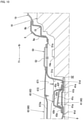
- FIG. 8 is an enlarged sectional view of essential portions on a vehicle front side in FIG. 4
- FIG. 9 is a perspective view of an appearance of a kick-up reinforcing element 50 (as a possible implementation of a kick-up reinforcing portion) viewed from the vehicle front side
- FIG. 10 is an enlarged sectional view of essential portions on a vehicle rear side in FIG. 4
- FIG. 11 is a sectional view taken in the direction of arrow D-D in FIG. 3
- FIG. 12 is a sectional view taken in the direction of arrow E-E in FIG. 3
- FIG. 13 is perspective view of an appearance of a second support bracket 62 viewed from the vehicle rear side.
- FIGS. 1 , 2 , and 3 a side sill outer portion 7A is not shown, and in FIGS. 4 , 6 to 8, and 10, a battery unit 16 disposed on a vehicle lower side of a front floor panel 8 is not shown in detail.
- arrows Fr and Rr show a front-rear direction
- the arrow Fr shows a front side
- the arrow Rr shows a rear side
- arrows Rh and Lh show a vehicle-width direction
- the arrow Rh shows a right direction
- the arrow Lh shows a left direction.
- an instrument panel 2 is disposed in a vehicle interior front part, and a center console 3 and a shift lever 4 are disposed on the vehicle lower side substantially at a middle of the instrument panel 2 in the vehicle-width direction.
- two front seats are disposed with the center console 3 therebetween, and a rear seat is disposed on the vehicle rear side of the center console 3.
- the center console 3 may include a center console front part 3A on the vehicle lower side of the instrument panel 2, and a center console rear part 3B connected to the vehicle rear side of the center console front part 3A.
- the center console rear part 3B integrally includes a design panel covering a base of the shift lever 4, and on the vehicle rear side of the design panel, a cup holder 3a and an arm rest 3b are disposed in this order.
- the shift lever 4 may be fixedly placed on a console support bracket 60 (as a possible implementation of a long member) described later via a shift lever support bracket 5.
- the shift lever support bracket 5 has a front part fastened to an upper surface of a first floor cross member 30 described later, and a rear part fastened to an upper surface of a standing bracket 70.
- the lower vehicle body in the vehicle interior part of the electric vehicle 1 may include a dash panel 6 that divides a motor room from the vehicle interior in a vehicle front-rear direction, a pair of left and right side sills 7 extending toward the vehicle rear side from lower parts of opposite ends of the dash panel 6 in the vehicle-width direction, a front floor panel 8 that is disposed between the left and right side sills 7 and forms a vehicle interior floor surface, a kick-up portion 9 raised from a rear end of the front floor panel 8 toward a vehicle upper side, and a rear floor panel 10 connected a rear end of the kick-up portion 9.
- a dash panel 6 that divides a motor room from the vehicle interior in a vehicle front-rear direction
- a pair of left and right side sills 7 extending toward the vehicle rear side from lower parts of opposite ends of the dash panel 6 in the vehicle-width direction
- a front floor panel 8 that is disposed between the left and right side sills 7 and forms a vehicle interior floor surface
- the lower vehicle body of the electric vehicle 1 may include a pair of left and right floor frame upper portions 11 extending across the dash panel 6 and the front floor panel 8 in the vehicle front-rear direction, and a pair of left and right floor frame lower portions 12 (see FIG. 3 ) (as a possible implementation of a pair of left and right floor frames) extending from a rear end of the floor frame upper portion 11 toward the vehicle rear side.
- the lower vehicle body of the electric vehicle 1 may further include, as shown in FIGS. 1 to 4 and 8 , a first floor cross member 30 and a second floor cross member 40 each connecting the left and right side sills 7 in the vehicle-width direction.
- the lower vehicle body structure may also have just one floor cross member or more than two floor cross members.
- the lower vehicle body of the electric vehicle 1 may include a kick-up reinforcing element 50 that connects a portion near the rear end of the front floor panel 8 and the kick-up portion 9, the console support bracket 60 that supports the shift lever 4 and the center console 3, and the standing bracket 70 that supports the console support bracket 60 from the vehicle lower side.
- the dash panel 6 may be a panel member having a thickness in the vehicle front-rear direction, and has a lower part curved toward the vehicle rear side. As shown in FIGS. 2 to 4 , the dash panel 6 has, substantially at the middle in the vehicle-width direction, a tunnel-shaped portion 6a expanding like a tunnel extending from a vehicle front upper side toward a vehicle rear lower side.
- the tunnel-shaped portion 6a may be formed of a separate member covering an opening that is cut substantially at the middle of the dash panel 6 in the vehicle-width direction, and joined to the dash panel 6 and thus integrated with the dash panel 6.
- the left and right side sills 7 each may form a substantially rectangular closed vertical section along the vehicle-width direction (see FIG. 6 ).
- the side sill 7 may include a side sill outer portion 7A (see FIG. 6 ) having a substantially hat-shaped vertical section along the vehicle-width direction that protrudes toward a vehicle-width-direction outer side, and a side sill inner portion 7B (see FIG. 6 ) having a substantially hat-shaped vertical section along the vehicle-width direction that protrudes toward a vehicle-width-direction inner side.
- the front floor panel 8 may be a substantially flat panel member having a thickness in a vehicle up-down direction, and has a front end joined to a lower end of the dash panel 6 and a rear end joined to a lower end of the kick-up portion 9 described later.
- a front opening S1 may be formed that is cut continuously with an internal space of the tunnel-shaped portion 6a of the dash panel 6 substantially at the middle in the vehicle-width direction.
- a rear opening S2 (as a possible implementation of a floor panel opening) may be formed that is cut continuously with an internal space of the kick-up reinforcing element 50 described later substantially at the middle in the vehicle-width direction.
- an expanding member 14 may be joined that covers the front opening S1 and expands toward the vehicle upper side continuously with the tunnel-shaped portion 6a of the dash panel 6.
- the expanding member 14 has a length in the vehicle front-rear direction from a front end of the front floor panel 8 to a front end of the first floor cross member 30 described later.
- the expanding member 14 may include a pair of left and right side walls 14a facing each other in the vehicle-width direction to form a substantially triangular shape in side view, a rear wall 14b inclined so that a rear end is located on the vehicle lower side with respect to a front end, and a flange 14c along lower ends of the side walls 14a and a lower end of the rear wall 14b, and has a substantially box shape opening on the vehicle front side and the vehicle lower side.
- the expanding member 14 may form a substantially tunnel-shaped space continuous with the tunnel-shaped portion 6a of the dash panel 6 by front parts of the side walls 14a and a front part of the rear wall 14b being joined to the tunnel-shaped portion 6a of the dash panel 6 and the flange 14c being joined to an upper surface of the front floor panel 8.
- the kick-up portion 9 may include a kick-up front surface 9a extending from the rear end of the front floor panel 8 toward the vehicle upper side, and a kick-up upper surface 9b extending from an upper end of the kick-up front surface 9a toward the vehicle rear side, and has a substantially L-shaped vertical section along the vehicle front-rear direction.
- the lower-vehicle body structure may have a third cross member.
- the third cross member 15 extending in the vehicle-width direction is joined across an upper part of the kick-up front surface 9a and a front part of the kick-up upper surface 9b.
- the third cross member 15 may have a substantially L-shaped vertical section along the vehicle front-rear direction with a corner on the vehicle rear lower side, and forms, together with the kick-up portion 9, a substantially rectangular closed section extending in the vehicle-width direction.
- the rear floor panel 10 may be a panel member having a thickness in the vehicle up-down direction, and joined to a rear end of the kick-up upper surface 9b of the kick-up portion 9. Although not shown in detail, a rear seat surface may be fixedly placed on an upper surface of the rear floor panel 10.
- each floor frame upper portion 11 may be disposed across a vehicle interior inner side of a lower part of the dash panel 6 and an upper surface of the front floor panel 8.
- the floor frame upper portion 11 has a substantially hat-shaped vertical section along the vehicle-width direction protruding toward the vehicle upper side, and may be joined to the dash panel 6 and the front floor panel 8 to form a substantially rectangular closed section extending in the vehicle front-rear direction.
- the floor frame upper portion 11 may be disposed near the vehicle-width-direction outer side to extend near the side sill 7 in plan view, and may have a rear end located on the vehicle-width-direction outer side with respect to a front end.
- each floor frame lower portion 12 may be disposed on a lower surface of the front floor panel 8 continuously with the floor frame upper portion 11 in plan view.
- the floor frame lower portion 12 may have a rear end located on the vehicle-width-direction outer side with respect to a front end.
- the floor frame lower portions 12 may be disposed to extend near the left and right side sills 7.
- the floor frame lower portion 12 may have a substantially hat-shaped vertical section along the vehicle-width direction protruding toward the vehicle lower side, and may be joined to the lower surface of the front floor panel 8 to form a substantially rectangular closed section extending in the vehicle front-rear direction.
- a battery unit 16 that supplies power to the rotary electric machine may be disposed in an area from a portion near the front end of the front floor panel 8 to the rear floor panel 10.
- the battery unit 16 may include a plurality of high-voltage battery bodies electrically connected, a harness that electrically connects the rotary electric machine and the plurality of battery bodies, a selector switch 16a that switches between conduction between the rotary electric machine and the battery bodies and interruption of the conduction, and the like.
- the selector switch 16a may be disposed on the vehicle lower side of the rear opening S2 in the front floor panel 8.
- the first floor cross member 30 substantially linearly connects the left and right side sills 7 in a position adjacent, on the vehicle rear side, to the rear end of the expanding member 14 on the front floor panel 8.
- the first floor cross member 30 may form, together with the front floor panel 8, a closed vertical section along the vehicle front-rear direction that extends in the vehicle-width direction.
- the first floor cross member 30 may have, in a vertical section along the vehicle-width direction, an upper enlarged section 30a with a section enlarged toward the vehicle upper side substantially at the middle in the vehicle-width direction so that an upper surface of the first floor cross member 30 substantially at the middle in the vehicle-width direction may be located on the vehicle upper side with respect to the upper surface on the vehicle-width-direction outer side.
- the second floor cross member 40 substantially linearly connects the left and right side sills 7 at a predetermined distance from the first floor cross member 30 on the vehicle rear side.
- the second floor cross member 40 may form, together with the front floor panel 8, a closed vertical section along the vehicle front-rear direction that extends in the vehicle-width direction.
- the second floor cross member 40 may have, in a vertical section along the vehicle-width direction, an upper enlarged section 40a with a section enlarged toward the vehicle upper side substantially at the middle in the vehicle-width direction so that an upper surface of the second floor cross member 40 substantially at the middle in the vehicle-width direction may be located on the vehicle upper side with respect to the upper surface on the vehicle-width-direction outer side.
- the kick-up reinforcing element 50 may cover the rear opening S2 in the front floor panel 8 and may connect the kick-up front surface 9a of the kick-up portion 9 and the front floor panel 8 substantially at the middle in the vehicle-width direction.
- the console support bracket 60 may connect the expanding member 14 of the front floor panel 8 and the kick-up reinforcing element 50 in the vehicle front-rear direction.
- console support bracket 60 may be fastened to the upper surface of the first floor cross member 30, the upper surface of the second floor cross member 40, and an upper surface of the standing bracket 70.
- the shift lever support bracket 5 that supports the shift lever 4 and the center console rear part 3B may be fixedly placed.
- the standing bracket 70 may connect and support the upper surface of the front floor panel 8 and an upper surface of the console support bracket 60 between the first floor cross member 30 and the second floor cross member 40.
- the first floor cross member 30, the second floor cross member 40, the kick-up reinforcing element 50, and the console support bracket 60 will be further described in more detail.
- the first floor cross member 30 particularly includes a middle member 31 extending in the vehicle-width direction between the floor frame lower portions 12, a pair of left and right end members 32 joined to opposite ends of the middle member 31 in the vehicle-width direction, a cross member reinforcing element 33 that forms the upper enlarged section 30a, and a pair of left and right front seat outer securing members 34 on which front parts of seat slide rails 17 on the vehicle-width-direction outer side are fixedly placed.
- the seat slide rails 17 may be a pair of left and right seat slide rails 17 that support a front seat 18.
- the middle member 31 may have a substantially hat-shaped vertical section along the vehicle front-rear direction that protrudes toward the vehicle upper side.
- the middle member 31 may integrally include a member front surface 31a as a surface on the vehicle front side, a member rear surface 31b as a surface on the vehicle rear side, a member upper surface 31c as a surface on the vehicle upper side, a front flange 31d extending from a lower end of the member front surface 31a toward the vehicle front side, and a rear flange 31e extending from a lower end of the member rear surface 31b toward the vehicle rear side.
- the front flange 31d and the rear flange 31e of the middle member 31 may be joined to the upper surface of the front floor panel 8.
- the member upper surface 31c of the middle member 31 may have a substantially rectangular flat shape in plan view, and may be formed substantially in the same position in the vehicle up-down direction as an inner portion upper surface 7a of the side sill inner portion 7B.
- the left and right end members 32 each have a substantially hat-shaped vertical section along the vehicle front-rear direction that protrudes toward the vehicle upper side, and continuously extend from the middle member 31 in the vehicle-width direction.
- the end member 32 integrally includes a member upper surface 32a located substantially in the same position in the vehicle up-down direction as the member upper surface 31c of the middle member 31, a member front surface 32b (see FIG. 3 ) extending from a front end of the member upper surface 32a toward the vehicle lower side, a member rear surface 32c extending from a rear end of the member upper surface 32a toward the vehicle lower side, a front flange extending from a lower end of the member front surface 32b toward the vehicle front side, and a rear flange extending from a lower end of the member rear surface 32c toward the vehicle rear side.
- the front flange and the rear flange of the end member 32 may be joined to the upper surface of the front floor panel 8, and an extending portion from the member upper surface 32a on the vehicle-width-direction outer side may be joined to the inner portion upper surface 7a of the side sill 7.
- the cross member reinforcing element 33 may have a substantially gate-shaped vertical section along the vehicle front-rear direction that opens on the vehicle lower side, and may form, together with the middle member 31, a closed section extending in the vehicle-width direction.
- the cross member reinforcing element 33 may integrally include an upper surface 33a located on the vehicle upper side with respect to the member upper surface 31c of the middle member 31, a front surface 33b extending from a front end of the upper surface 33a toward the vehicle lower side, a rear surface 33c extending from a rear end of the upper surface 33a toward the vehicle lower side, and a pair of left and right side surfaces 33d extending from opposite ends of the upper surface 33a in the vehicle-width direction toward the vehicle lower side.
- the cross member reinforcing element 33 may integrally include a pair of left and right side flanges 33e extending from lower ends of the side surfaces 33d toward the vehicle-width-direction outer side, and may have a hat-shaped vertical section along the vehicle-width direction and forms a closed section together with the member upper surface 31c of the middle member 31.
- the front surface 33b may be joined to the member front surface 31a of the middle member 31
- the rear surface 33c may be joined to the member rear surface 31b of the middle member 31
- the side flanges 33e may be joined to the member upper surface 31c of the middle member 31.
- front seat inner securing portions 33f to which front parts of seat slide rails 17 on the vehicle-width-direction inner side are fastened may be integrally formed with opposite ends of the upper surface 33a of the cross member reinforcing element 33 in the vehicle-width direction.
- the front seat inner securing portions 33f may be formed substantially in the same position in the vehicle up-down direction as the middle of the upper surface 33a in the vehicle-width direction.
- a fastening bracket 35 having a substantially M-shaped vertical section along the vehicle-width direction may be fastened by fastening bolts T1 to the upper surface 33a on the vehicle-width-direction inner side with respect to the front seat inner securing portions 33f.
- two weld bolts 36 may be joined to an upper surface of the fastening bracket 35 so as to protrude toward the vehicle upper side. As shown in FIG. 8 , the weld bolts 36 co-fasten the shift lever support bracket 5 and the console support bracket 60 (a bracket upper surface 672 of a second support bracket 62 described later).
- the front seat outer securing member 34 may have a substantially box shape expanding toward the vehicle upper side with respect to the member upper surface 32a of the end member 32.
- the second floor cross member 40 particularly includes a middle member 41 extending in the vehicle-width direction between the floor frame lower portions 12, a pair of left and right end members 42 joined to opposite ends of the middle member 41 in the vehicle-width direction, and a cross member reinforcing element 43 that forms the upper enlarged section 40a.
- the middle member 41 may have a substantially hat-shaped vertical section along the vehicle front-rear direction that protrudes toward the vehicle upper side.
- the middle member 41 may integrally include a member front surface 41a as a surface on the vehicle front side, a member rear surface 41b as a surface on the vehicle rear side, a member upper surface 41c as a surface on the vehicle upper side, a front flange 41d extending from a lower end of the member front surface 41a toward the vehicle front side, and a rear flange 41e extending from a lower end of the member rear surface 41b toward the vehicle rear side.
- the front flange 41d and the rear flange 41e of the middle member 41 may be joined to the upper surface of the front floor panel 8.
- the left and right end members 42 each have a substantially hat-shaped vertical section along the vehicle front-rear direction that protrudes toward the vehicle upper side, and continuously extend from the middle member 41 in the vehicle-width direction.
- the end member 42 may integrally include a member upper surface 42a located substantially in the same position in the vehicle up-down direction as the member upper surface 41c of the middle member 41, a member front surface 42b (see FIG. 3 ) extending from a front end of the member upper surface 42a toward the vehicle lower side, a member rear surface 42c extending from a rear end of the member upper surface 42a toward the vehicle lower side, a front flange extending from a lower end of the member front surface 42b toward the vehicle front side, and a rear flange extending from a lower end of the member rear surface 42c toward the vehicle rear side.
- the front flange and the rear flange of the end member 42 may be joined to the upper surface of the front floor panel 8, and an extending portion from the member upper surface 42a (a front seat outer securing portion 42f described later) on the vehicle-width-direction outer side may be joined to the inner portion upper surface 7a of the side sill 7.
- the front seat outer securing portion 42f to which the seat slide rail 17 on the vehicle-width-direction outer side is fastened may be integrally formed with the vehicle-width-direction outer side of the member upper surface 42a of the end member 42 so as to expand toward the vehicle upper side.
- the cross member reinforcing element 43 may have a substantially hat-shaped vertical section along the vehicle front-rear direction that protrudes toward the vehicle upper side, and forms, together with the middle member 41, a closed section that extends in the vehicle-width direction.
- the cross member reinforcing element 43 may integrally include an upper surface 43a located on the vehicle upper side with respect to the member upper surface 41c of the middle member 41, a front surface 43b extending from a front end of the upper surface 43a toward the vehicle lower side, a rear surface 43c extending from a rear end of the upper surface 43a toward the vehicle lower side, a pair of left and right side surfaces 43d extending from opposite ends of the upper surface 43a in the vehicle-width direction toward the vehicle lower side, a front flange 43e extending from a lower end of the front surface 43b toward the vehicle front side, and a rear flange 43f extending from a lower end of the rear surface 43c toward the vehicle rear side.
- the cross member reinforcing element 43 may integrally include a pair of left and right side flanges 43g extending from lower ends of the side surfaces 43d toward the vehicle-width-direction outer side so as to have a hat-shaped vertical section along the vehicle-width direction and form a closed section together with the member upper surface 41c of the middle member 41.
- the front flange 43e may be joined via the front flange 41d of the middle member 41 to the upper surface of the front floor panel 8
- the rear flange 43f may be joined via the rear flange 41e of the middle member 41 to the upper surface of the front floor panel 8
- the side flange 43g may be joined to the member upper surface 41c of the middle member 41.
- front seat inner securing portions 43h to which rear parts of the seat slide rails 17 on the vehicle-width-direction inner side are fastened may be integrally formed with opposite ends of the upper surface 43a of the cross member reinforcing element 43 in the vehicle-width direction in substantially the same position in the vehicle up-down direction as the middle of the upper surface 43a in the vehicle-width direction.
- two weld nuts 44 into which fastening bolts T2 are threaded may be joined to a lower side of the upper surface 43a at a predetermined interval in the vehicle-width direction on the vehicle-width-direction inner side with respect to the front seat inner securing portions 43h.
- the console support bracket 60 (second securing portions 673b of the second support bracket 62 described later) may be fastened to the weld nuts 44 by the fastening bolts T2.
- the kick-up reinforcing element 50 may include a body member 51 joined to the kick-up front surface 9a of the kick-up portion 9 and the upper surface of the front floor panel 8 on the vehicle front lower side of the kick-up front surface 9a, and a cover member 52 removably provided on an upper surface of the body member 51.
- the body member 51 may have a substantially L-shaped vertical section along the vehicle front-rear direction, and a substantially hat-shaped vertical section along the vehicle-width direction that protrudes toward the vehicle upper side.
- the body member 51 may have a substantially box shape opening on the vehicle lower side and the vehicle rear side.
- the body member 51 may integrally include an upper surface 51a formed substantially in the same position in the vehicle up-down direction as the lower end of the kick-up front surface 9a of the kick-up portion 9, a pair of left and right side walls 51b extending from opposite ends of the upper surface 51a in the vehicle-width direction toward the vehicle lower side, and a front wall 51c extending from a front end of the upper surface 51a toward the vehicle lower side, and may have a substantially box shape covering the rear opening S2 in the front floor panel 8.
- the body member 51 may include extending portions from lower ends of the side walls 51b toward the vehicle-width-direction outer side like flanges, and an extending portion from a lower end of the front wall 51c toward the vehicle front side like a flange, which integrally form a substantially U-shaped flange 51d in plan view along the lower ends of the left and right side walls 51b and the lower end of the front wall 51c.
- the upper surface 51a and the left and right side walls 51b of the body member 51 may be joined to the kick-up front surface 9a of the kick-up portion 9, and the flange 51d may be joined to the upper surface of the front floor panel 8.
- weld nuts 53 into which fastening bolts T3 are threaded through openings provided on the vehicle front upper side may be joined to inner surfaces of the side walls 51b of the body member 51.
- a rear part of the console support bracket 60 may be fastened to the weld nuts 53 by the fastening bolts T3.
- the upper surface 51a may have a substantially rectangular opening S3 in plan view in an area facing the selector switch 16a provided on an upper surface of the battery unit 16 and the rear opening S2 in the front floor panel 8.
- weld bolts 54 protruding toward the vehicle upper side may be joined to the upper surface 51a around the opening S3.
- the weld bolts 54 co-fasten the rear part of the console support bracket 60 and the cover member 52.
- the cover member 52 may have a predetermined thickness in the vehicle up-down direction and may be substantially flat to cover the opening S3 in the body member 51. As shown in FIGS. 10 and 11 , the cover member 52 may be co-fastened by the weld bolts 54 to the body member 51 with the rear part of the console support bracket 60 therebetween.
- the console support bracket 60 may connect the expanding member 14 of the front floor panel 8 and the kick-up reinforcing element 50 in the vehicle front-rear direction.
- the console support bracket 60 may include, in the vehicle interior of the electric vehicle 1, a first support bracket 61 that supports the center console front part 3A, and a second support bracket 62 that supports the shift lever 4 and the center console rear part 3B.
- the first support bracket 61 may include a bracket body 63 joined to the expanding member 14 of the front floor panel 8, and a reinforcement 64 that reinforces a rear part of the bracket body 63.
- the first support bracket 61 may have substantially the same length in the vehicle front-rear direction as the expanding member 14 of the front floor panel 8.
- the bracket body 63 may include a pair of left and right bracket side walls 631 (as a possible implementation of a pair of left and right side walls of a long member) facing each other in the vehicle-width direction, and a bracket upper surface 632 connecting upper ends of the bracket side walls 631, and may have a substantially gate shape in front view.
- the bracket upper surface 632 may be recessed toward the vehicle lower side, and may have a recessed groove 632a extending in the vehicle front-rear direction substantially at the middle in the vehicle-width direction.
- the recessed groove 632a may be recessed from a substantial middle to a rear end of the bracket upper surface 632 in the vehicle front-rear direction.
- the bracket upper surface 632 spaced apart from the rear wall 14b of the expanding member 14 on the vehicle front side with respect to the reinforcement 64 of the first support bracket 61 described later may be connected to the rear wall 14b of the expanding member 14 via a connecting bracket 19 having a substantially Z-shaped section.
- the reinforcement 64 of the first support bracket 61 may be joined to an inner surface of the rear part of the bracket body 63.
- the reinforcement 64 may integrally include a pair of left and right side surfaces 641 joined to upper parts of the bracket side walls 631 of the bracket body 63, and an upper surface 642 joined to the bracket upper surface 632 of the bracket body 63.
- weld nuts 65 into which fastening bolts T4 are threaded through openings provided in the bracket side walls 631 of the bracket body 63 may be welded to rear parts of the side surfaces 641 of the reinforcement 64 of the first support bracket 61.
- the front part of the second support bracket 62 may be fastened to the weld nuts 65 by the fastening bolts T4.
- weld bolts 66 protruding toward the vehicle upper side may be joined to a rear part of the upper surface 642 through openings provided in the bracket upper surface 632 of the bracket body 63 at a predetermined interval in the vehicle-width direction.
- the front part of the second support bracket 62 may be fastened to the weld bolts 66.
- the second support bracket 62 may include a bracket body 67 connected to a rear part of the first support bracket 61, and a reinforcement 68 that reinforces a front part of the bracket body 67.
- the bracket body 67 may integrally include a pair of left and right bracket side walls 671 facing each other in the vehicle-width direction, and a bracket upper surface 672 connecting upper ends of the bracket side walls 671 in the vehicle-width direction, and has a substantially gate-shaped vertical section along the vehicle-width direction that opens on the vehicle lower side.
- the left and right bracket side walls 671 may be substantially flat with a longer length in the vehicle front-rear direction than in the vehicle up-down direction.
- Each bracket side wall 671 may have a length in the vehicle up-down direction shorter than a length from the bracket upper surface 672 to the upper surface of the front floor panel 8 in the vehicle up-down direction.
- a flange 673 extending on the vehicle-width-direction outer side may be integrally formed with a lower end of the bracket side wall 671 from a front end to a rear end.
- the flange 673 may include, at a predetermined interval in the vehicle front-rear direction, a first securing portion 673a fastened to the upper surface of the first floor cross member 30, and a second securing portion 673b fastened to the upper surface of the second floor cross member 40, which further extend toward the vehicle-width-direction outer side as flanges.
- the bracket side wall 671 may have, near a front end, a bolt insertion hole 671a through which the fastening bolt T4 can be inserted, and may have, near a rear end, a bolt insertion hole 671b through which the fastening bolt T3 can be inserted.
- the shift lever support bracket 5 that supports the shift lever 4 from the vehicle lower side, and the center console rear part 3B may be fixedly placed in this order from the vehicle front side.
- the bracket upper surface 672 may have a substantially rectangular flat shape in plan view that has a substantially constant length in the vehicle-width direction and may be long in the vehicle front-rear direction.
- the bracket upper surface 672 may be recessed toward the vehicle lower side continuously with the recessed groove 632a in the first support bracket 61, and may have a recessed groove 672a extending in the vehicle front-rear direction substantially at the middle in the vehicle-width direction.
- the recessed groove 672a in the bracket upper surface 672 may have a length from a front end of the bracket upper surface 672 to the vicinity of the second securing portion 673b in the vehicle front-rear direction.
- the recessed groove 632a in the first support bracket 61 and the recessed groove 672a in the second support bracket 62 increase rigidity of the first support bracket 61 and the second support bracket 62, and may be also formed as spaces in which a wire harness (not shown) routed along the vehicle front-rear direction in the vehicle interior is accommodated.
- the bracket upper surface 672 may have, near a front end, two bolt insertion holes 672b through which the weld bolts 66 of the first support bracket 61 can be inserted, and may have two bolt insertion holes 672c through which the weld bolts 36 of the fastening bracket 35 of the first floor cross member 30 can be inserted, substantially in the same position in the vehicle front-rear direction as the first securing portion 673a.
- the bracket upper surface 672 may have, between the first securing portion 673a and the second securing portion 673b, a plurality of bolt insertion holes 672d through which weld bolts (not shown) provided on the standing bracket 70 for fastening the bracket body 67 to the standing bracket 70 can be inserted, and may have, near a rear end, two bolt insertion holes 672e through which two weld bolts 54 on the vehicle front side among the four weld bolts 54 of the kick-up reinforcing element 50 can be inserted.
- the reinforcement 68 of the second support bracket 62 may be joined to an inner surface of the front part of the bracket body 67.
- the reinforcement 68 may integrally include a pair of left and right side surfaces 681 joined to the bracket side walls 671 of the bracket body 67, and an upper surface 682 joined to the bracket upper surface 672 of the bracket body 67, and forms a substantially gate shape in front view.
- a rear part of the bracket side wall 631 of the first support bracket 61 and a front part of the bracket side wall 671 of the second support bracket 62 may be fastened by the fastening bolts T4, and a rear part of the bracket upper surface 632 of the first support bracket 61 and a front part of the bracket upper surface 672 of the second support bracket 62 may be fastened by the weld bolts 66, and thus the first support bracket 61 and the second support bracket 62 may be connected in the vehicle front-rear direction.
- console support bracket 60 may be connected to the expanding member 14 by the bracket side walls 631 and the bracket upper surface 632 of the first support bracket 61 being joined to the side walls 14a and the rear wall 14b of the expanding member 14, respectively.
- the bracket side walls 671 of the second support bracket 62 may be fastened by the fastening bolts T3 to the side walls 51b of the kick-up reinforcing element 50, and the bracket upper surface 672 of the second support bracket 62 may be co-fastened by the weld bolts 54 to the upper surface 51a of the kick-up reinforcing element 50 together with the cover member 52.
- console support bracket 60 may connect the expanding member 14 of the front floor panel 8 and the kick-up reinforcing element 50 in the vehicle front-rear direction.
- the bracket upper surface 672 of the second support bracket 62 may be co-fastened by the weld bolts 36 to the fastening bracket 35 of the first floor cross member 30 together with the front part of the shift lever support bracket 5.
- the first securing portion 673a of the second support bracket 62 may be fastened by the fastening bolts T1 to the cross member reinforcing element 33 of the first floor cross member 30, and the second securing portion 673b of the second support bracket 62 may be fastened by the fastening bolts T2 to the cross member reinforcing element 43 of the second floor cross member 40.
- the lower vehicle-body structure of the electric vehicle 1 that uses output from the rotary electric machine as a drive force may include the pair of left and right side sills 7 extending in the vehicle front-rear direction, the substantially flat front floor panel 8 disposed between the side sills 7.
- the lower vehicle-body structure my further include the first floor cross member 30 and the second floor cross member 40 disposed on the upper surface of the front floor panel 8 and connecting the left and right side sills 7 in the vehicle-width direction and the pair of left and right floor frame lower portions 12 disposed on the front floor panel 8 and extending in the vehicle front-rear direction.
- the lower vehicle-body structure may further include the battery unit 16 that may be disposed between the left and right floor frame lower portions 12 and on the vehicle lower side of the front floor panel 8, the kick-up portion 9 raised from the rear end of the front floor panel 8 toward the vehicle upper side, the rear floor panel 10 connected to the vehicle rear side of the kick-up portion 9, and the kick-up reinforcing element 50 connecting the substantial middle of the kick-up portion 9 in the vehicle-width direction and the front floor panel 8 in front of the substantial middle of the kick-up portion 9. This can ensure desired resistance to rear-end collision even if the tunnel of the front floor panel 8 is eliminated.
- the lower vehicle-body structure of the electric vehicle 1 includes the kick-up reinforcing element 50 connecting the kick-up portion 9 and the front floor panel 8 for reinforcement, the support rigidity of the kick-up portion 9 against a load in the vehicle front-rear direction increases, even if the tunnel is eliminated.
- the lower vehicle-body structure of the electric vehicle 1 can prevent the rear floor panel 10 from being deformed to curve toward the vehicle upper side around the lower end of the kick-up portion 9 when a collision load is applied from the vehicle rear side.
- the lower vehicle-body structure of the electric vehicle 1 can ensure desired resistance to rear-end collision even if the tunnel of the front floor panel 8 is eliminated.
- the lower vehicle-body structure of the electric vehicle 1 includes the first floor cross member 30 and the second floor cross member 40 each connecting the left and right side sills 7 in the vehicle-width direction, a highly efficient transfer, from one side sill 7 to the other side sill 7, of a collision load from a vehicle lateral side is provided.
- the lower vehicle-body structure of the electric vehicle 1 can increase rigidity of a vehicle interior floor surface against the collision load from the vehicle lateral side.
- the kick-up reinforcing element 50 may integrally include the pair of left and right side walls 51b facing each other in the vehicle-width direction, the front wall 51c connecting the front ends of the side walls 51b, and the upper surface 51a connecting the upper ends of the side walls 51b, and the side walls 51b and the front wall 51c of the kick-up reinforcing element 50 may be joined to the front floor panel 8.
- the lower vehicle-body structure of the electric vehicle 1 can stably ensure desired resistance to rear-end collision.
- the kick-up reinforcing element 50 may include the pair of left and right side walls 51b, the front wall 51c, and the upper surface 51a, and thus the lower vehicle-body structure of the electric vehicle 1 can increase rigidity of the kick-up reinforcing element 50 as compared to, for example, when the pair of left and right side walls 51b are not provided.
- the front wall 51c and the side walls 51b of the kick-up reinforcing element 50 may be joined to the front floor panel 8, and thus the lower vehicle-body structure of the electric vehicle 1 can stably transfer the collision load from the vehicle rear side to the front floor panel 8.
- the lower vehicle-body structure of the electric vehicle 1 can further prevent deformation of the kick-up portion 9 due to the collision load from the vehicle rear side.
- the lower vehicle-body structure of the electric vehicle 1 can stably ensure desired resistance to rear-end collision.
- the console support bracket 60 is provided that is long in the vehicle front-rear direction, and may have the front part connected to the vehicle body and the rear part secured to the kick-up reinforcing element 50.
- the lower vehicle-body structure of the electric vehicle 1 can use the kick-up reinforcing element 50 as a support member that supports the rear part of the console support bracket 60.
- the lower vehicle-body structure of the electric vehicle 1 can eliminate the need to separately provide a support member that supports the rear part of the console support bracket 60, and ensure support rigidity of the console support bracket 60 that is long in the vehicle front-rear direction.
- the front part of the console support bracket 60 may be connected to the vehicle body, and thus the lower vehicle-body structure of the electric vehicle 1 can transfer the collision load applied from the vehicle rear side to the kick-up reinforcing element 50, via the console support bracket 60 further to the vehicle front side.
- the lower vehicle-body structure of the electric vehicle 1 can increase rigidity of the kick-up portion 9 against the collision load from the vehicle rear side by cooperation between the console support bracket 60 and the kick-up reinforcing element 50.
- the lower vehicle-body structure of the electric vehicle 1 can more stably ensure desired resistance to rear-end collision.
- the console support bracket 60 has the substantially gate-shaped vertical section along the vehicle-width direction with the pair of left and right bracket side walls 671 facing each other in the vehicle-width direction, and the bracket side walls 671 of the console support bracket 60 may be secured to the first floor cross member 30, the second floor cross member 40, and the side walls 51b of the kick-up reinforcing element 50.
- the lower vehicle-body structure of the electric vehicle 1 can reduce a length of each bracket side wall 671 of the console support bracket 60 in the vehicle up-down direction as compared to when the bracket side wall 671 is secured to the front floor panel 8.
- the lower vehicle-body structure of the electric vehicle 1 can reduce weight of the console support bracket 60 as compared to when the bracket side wall 671 is secured to the front floor panel 8.
- the battery unit 16 may include the selector switch 16a that is located on the vehicle lower side of the kick-up reinforcing element 50 and switches between conduction with outside and interruption of the conduction
- the front floor panel 8 may include the rear opening S2 that opens in the area facing the selector switch 16a of the battery unit 16
- the kick-up reinforcing element 50 may include the opening S3 that opens in the area of the upper surface 51a facing the rear opening S2, and the removable cover member 52 covering the opening S3.
- the lower vehicle-body structure of the electric vehicle 1 allows easy access to the selector switch 16a of the battery unit 16 simply by removing the cover member 52 of the kick-up reinforcing element 50.
- the lower vehicle-body structure of the electric vehicle 1 can ensure desired resistance to rear-end collision, and also increase maintainability of the electric vehicle 1.
- the kick-up reinforcing element 50 may include the weld bolts 54 for mounting both the cover member 52 and the console support bracket 60.
- the lower vehicle-body structure of the electric vehicle 1 can use the weld bolts 54 both for mounting the cover member 52 and for mounting the console support bracket 60.
- the lower vehicle-body structure of the electric vehicle 1 can eliminate the need to separately provide, on the kick-up reinforcing element 50, a mounting portion for mounting the console support bracket 60.
- the lower vehicle-body structure of the electric vehicle 1 can increase rigidity of the kick-up portion 9 against the collision load from the vehicle rear side without increasing the number of components.
- the floor cross member of the present invention may correspond to the first floor cross member 30 and the second floor cross member 40 of the embodiment.
- the floor frame may correspond to the floor frame lower portion 12.
- the kick-up reinforcing portion may correspond to the kick-up reinforcing element 50.
- the long member may correspond to the console support bracket 60.
- the side walls of the long member may correspond to the bracket side walls 671 of the console support bracket 60.
- the floor panel opening may correspond to the rear opening S2.
- the mounting portion may correspond to the weld bolt 54.
- the present invention is not limited to the configuration of the above described embodiment, but may encompass various embodiments, e.g. based on only some of the above-mentioned correspondences.
- the separately formed expanding member 14 may be joined to the front part of the front floor panel 8, but not limited to this, the front part of the front floor panel 8 substantially at the middle in the vehicle-width direction may be expanded toward the vehicle upper side to integrally form the expanding member 14 with the front floor panel 8.
- the kick-up reinforcing element 50 that connects the rear part of the front floor panel 8 and the kick-up portion 9 is separately formed, but not limited to this, the kick-up reinforcing element 50 may be integrally formed with the front floor panel 8 or the kick-up portion 9.
- the first floor cross member 30 particularly includes the middle member 31, the pair of left and right end members 32, and the cross member reinforcing element 33, but not limited to this, the middle member 31 and the left and right end members 32 may be integrally formed. Alternatively, the middle member 31 and the cross member reinforcing element 33 may be integrally formed, or the middle member 31, the pair of left and right end members 32, and the cross member reinforcing element 33 may be integrally formed.
- the second floor cross member 40 particularly includes the middle member 41, the pair of left and right end members 42, and the cross member reinforcing element 43, but not limited to this, for example, the middle member 41 and the left and right end members 42 may be integrally formed.
- the middle member 41 and the cross member reinforcing element 43 may be integrally formed, or the middle member 41, the pair of left and right end members 42, and the cross member reinforcing element 43 may be integrally formed.
- the console support bracket 60 particularly includes the first support bracket 61 and the second support bracket 62 fastened to each other, but not limited to this, the first support bracket 61 and the second support bracket 62 may be joined to each other.
- the console support bracket 60 may include the first support bracket 61 and the second support bracket 62 (e.g. as separate components), but not limited to this, the first support bracket 61 and the second support bracket 62 may be integrally formed.
- the expanding member 14 as a front vehicle body and the kick-up reinforcing element 50 as a rear vehicle body are connected in the vehicle front-rear direction by the console support bracket 60 that supports the center console 3, the shift lever 4, and the shift lever support bracket 5, but not limited to this, the expanding member 14 and the kick-up reinforcing element 50 may be connected in the vehicle front-rear direction by the long member that transfers a load in the vehicle front-rear direction.
Claims (12)
- Untere Fahrzeugkarosseriestruktur eines Elektrofahrzeugs (1), das eine Ausgabe von einer rotierenden elektrischen Maschine als eine Antriebskraft verwendet, umfassend:ein Paar linke und rechte Seitenschweller (7), die sich in einer Front-Heck-Richtung des Fahrzeugs erstrecken;eine im Wesentlichen flache vordere Bodenplatte (8), die zwischen den Seitenschwellern (7) angeordnet ist;zumindest einen Bodenquerträger (30, 40), der an bzw. auf einer oberen Fläche bzw. Oberfläche des vorderen Bodenblechs (8) angeordnet ist und den linken und rechten Seitenschweller (10) in einer Fahrzeugbreitenrichtung (Lh-Rh) verbindet;ein Paar linke und rechte Bodenrahmen, die an bzw. auf der vorderen Bodenplatte (8) angeordnet sind und sich in Front-Heck-Richtung des Fahrzeugs erstrecken;eine Batterieeinheit, die zwischen dem linken und rechten Bodenrahmen und an einer Fahrzeugunterseite der vorderen Bodenplatte angeordnet ist;einen gekröpften bzw. hochgezogenen Abschnitt bzw. Kick-Up-Abschnitt (9), der von einem hinteren Ende der vorderen Bodenplatte (8) zu einer Fahrzeugoberseite hin angehoben bzw. erhöht ist;eine hintere Bodenplatte (10), die mit einer Fahrzeugheckseite des gekröpften bzw. hochgezogenen Abschnitts bzw. Kick-Up-Abschnitts (9) verbunden ist; undeinen gekröpften bzw. hochgezogenen Verstärkungsabschnitt bzw. Kick-up-Verstärkungsabschnitt (50), der eine im Wesentlichen Mitte des gekröpften bzw. hochgezogenen Abschnitts bzw. Kick-up-Abschnitts (9) in der Fahrzeugbreitenrichtung und die vordere Bodenplatte (8) vor der im Wesentlichen Mitte des gekröpften bzw. hochgezogenen Abschnitts bzw. Kick-up-Abschnitts (9) verbindet.
- Untere Fahrzeugkarosseriestruktur eines Elektrofahrzeugs nach Anspruch 1, wobei der Kick-up-Verstärkungsabschnitt (50) einstückig bzw. integral ein Paar linke und rechte Seitenwände (51b), die einander in der Fahrzeugbreitenrichtung (Lh-Rh) zugewandt sind, eine vordere Wand (51c), welche die vorderen Enden der Seitenwände (51b) verbindet, und eine obere Fläche bzw. Oberfläche (51a) enthält, welche die oberen Enden der Seitenwände (51b) verbindet.
- Untere Fahrzeugkarosseriestruktur eines Elektrofahrzeugs nach Anspruch 2, wobei die Seitenwände (51b) und die vordere Wand (51c) des Kick-Up-Verstärkungsabschnitts (50) mit der vorderen Bodenplatte (8) verbunden sind.
- Untere Fahrzeugkarosseriestruktur eines Elektrofahrzeugs nach Anspruch 2 oder 3, ferner umfassend ein langes Glied (60), das in der Front-Heck-Richtung (Fr-Rr) des Fahrzeugs lang ist und einen vorderen Teil, der mit einer Fahrzeugkarosserie verbunden ist, und einen hinteren Teil aufweist, der an dem Kick-up-Verstärkungsabschnitt (50) befestigt ist.
- Untere Fahrzeugkarosseriestruktur eines Elektrofahrzeugs nach Anspruch 3 und 4, wobei das lange Glied (60) einen im Wesentlichen torförmigen vertikalen Schnitt bzw. Querschnitt entlang der Fahrzeugbreitenrichtung (Lh-Rh) mit einem Paar linker und rechter Seitenwände (671) aufweist, die einander in der Fahrzeugbreitenrichtung (Lh-Rh) zugewandt sind.
- Untere Fahrzeugkarosseriestruktur eines Elektrofahrzeugs nach Anspruch 5, wobei die Seitenwände (671) des langen Glieds (60) an dem Bodenquerträger (30, 40) und den Seitenwänden (51b) des Kick-up-Verstärkungsabschnitts (50) befestigt sind.
- Untere Fahrzeugkarosseriestruktur eines Elektrofahrzeugs nach einem der vorhergehenden Ansprüche, wobei die Batterieeinheit (16) einen Wahlschalter (16a) enthält, der sich an der Fahrzeugunterseite des Kick-Up-Verstärkungsabschnitts (50) befindet und der zum Umschalten zwischen Leitung mit Außenseite und Unterbrechung der Leitung angepasst ist.
- Untere Fahrzeugkarosseriestruktur eines Elektrofahrzeugs nach Anspruch 7, wobei die vordere Bodenplatte (8) eine Bodenplattenöffnung (S2) enthält, die sich in einem Bereich öffnet, der dem Wahlschalter (16a) der Batterieeinheit (16) zugewandt ist.
- Untere Fahrzeugkarosseriestruktur nach Anspruch 8, wobei der Kick-up-Verstärkungsabschnitt (50) eine Öffnung (S3), die sich in einem Bereich der oberen Fläche (51a) öffnet, der bzw. die der Bodenplattenöffnung (S2) zugewandt ist, und ein entfernbares Abdeckglied (52) enthält, das die Öffnung (S3) abdeckt.
- Untere Fahrzeugkarosseriestruktur eines Elektrofahrzeugs nach Anspruch 9, wobei der Kick-up-Verstärkungsabschnitt (50) einen Montageabschnitt (54) zum Montieren sowohl des Abdeckglieds (52) als auch des langen Glieds (60) enthält.
- Fahrzeugkarosseriestruktur eines Elektrofahrzeugs, umfassend die untere Fahrzeugkarosseriestruktur nach einem der vorhergehenden Ansprüche.
- Elektrofahrzeug, umfassend:
die untere Fahrzeugkarosseriestruktur nach einem der Ansprüche 1 bis 10 oder die Fahrzeugkarosseriestruktur nach Anspruch 11.
Applications Claiming Priority (1)
| Application Number | Priority Date | Filing Date | Title |
|---|---|---|---|
| JP2019092092A JP7275836B2 (ja) | 2019-05-15 | 2019-05-15 | 電動車両の下部車体構造 |
Publications (2)
| Publication Number | Publication Date |
|---|---|
| EP3738864A1 EP3738864A1 (de) | 2020-11-18 |
| EP3738864B1 true EP3738864B1 (de) | 2022-02-16 |
Family
ID=69779979
Family Applications (1)
| Application Number | Title | Priority Date | Filing Date |
|---|---|---|---|
| EP20161413.8A Active EP3738864B1 (de) | 2019-05-15 | 2020-03-06 | Untere fahrzeugkarosseriestruktur eines elektrofahrzeugs, fahrzeugkarosseriestruktur eines elektrofahrzeugs und elektrofahrzeug |
Country Status (4)
| Country | Link |
|---|---|
| US (1) | US11220298B2 (de) |
| EP (1) | EP3738864B1 (de) |
| JP (1) | JP7275836B2 (de) |
| CN (1) | CN111942478B (de) |
Families Citing this family (18)
| Publication number | Priority date | Publication date | Assignee | Title |
|---|---|---|---|---|
| JP6915592B2 (ja) * | 2018-06-15 | 2021-08-04 | マツダ株式会社 | 下部車体構造 |
| JP6881404B2 (ja) * | 2018-08-13 | 2021-06-02 | マツダ株式会社 | 下部車体構造 |
| JP7124649B2 (ja) * | 2018-11-08 | 2022-08-24 | トヨタ自動車株式会社 | 車両の下部車体構造 |
| US11091016B2 (en) * | 2019-03-06 | 2021-08-17 | Mazda Motor Corporation | Lower vehicle-body structure of vehicle |
| CN111942480B (zh) * | 2019-05-15 | 2022-11-22 | 马自达汽车株式会社 | 电动车辆的下部车体构造 |
| CN111942481B (zh) * | 2019-05-15 | 2022-10-28 | 马自达汽车株式会社 | 车辆的下部车体构造 |
| JP7316513B2 (ja) * | 2019-09-11 | 2023-07-28 | マツダ株式会社 | 車両の車体構造 |
| JP2021041817A (ja) * | 2019-09-11 | 2021-03-18 | マツダ株式会社 | 車両の車体構造 |
| CN111038588B (zh) * | 2019-12-27 | 2021-08-20 | 长城汽车股份有限公司 | 后副车架总成 |
| JP7240434B2 (ja) * | 2021-03-30 | 2023-03-15 | 本田技研工業株式会社 | 電動車両 |
| WO2023044429A1 (en) * | 2021-09-17 | 2023-03-23 | Shape Corp. | Vehicle crossmember and floor assembly |
| JP2023122974A (ja) * | 2022-02-24 | 2023-09-05 | マツダ株式会社 | 車体前部構造 |
| JP2023122972A (ja) * | 2022-02-24 | 2023-09-05 | マツダ株式会社 | 車体前部構造 |
| JP2023122971A (ja) * | 2022-02-24 | 2023-09-05 | マツダ株式会社 | 車体前部構造 |
| JP2023122976A (ja) * | 2022-02-24 | 2023-09-05 | マツダ株式会社 | 車体前部構造 |
| WO2023181240A1 (ja) * | 2022-03-24 | 2023-09-28 | 三菱自動車工業株式会社 | 駆動用電池パックの排気構造 |
| JP7239907B1 (ja) * | 2022-03-24 | 2023-03-15 | 三菱自動車工業株式会社 | 車両のサービスプラグ保護構造 |
| DE102023003563A1 (de) | 2022-09-06 | 2024-03-07 | Mercedes-Benz Group AG | Befestigungsstruktur |
Family Cites Families (33)
| Publication number | Priority date | Publication date | Assignee | Title |
|---|---|---|---|---|
| JPS58128970A (ja) * | 1982-01-27 | 1983-08-01 | Mazda Motor Corp | 自動車の車体構造 |
| JP4194142B2 (ja) * | 1998-10-07 | 2008-12-10 | 富士重工業株式会社 | 車体フロア構造及び車体フロア構造の製造方法 |
| DE10059912A1 (de) | 2000-12-01 | 2002-06-20 | Porsche Ag | Fahrzeug mit einer Bodenaufbaustruktur |
| JP4269866B2 (ja) * | 2003-09-30 | 2009-05-27 | マツダ株式会社 | 車両の下部車体構造 |
| US7331611B2 (en) * | 2004-06-30 | 2008-02-19 | Mazda Motor Corporation | Underbody structure of vehicle |
| JP4747812B2 (ja) * | 2005-12-01 | 2011-08-17 | マツダ株式会社 | 車両の下部車体構造 |
| JP4690450B2 (ja) * | 2008-12-19 | 2011-06-01 | 本田技研工業株式会社 | 車体フロア構造 |
| US8292356B2 (en) * | 2009-03-17 | 2012-10-23 | Mazda Motor Corporation | Lower vehicle-body structure of vehicle |
| JP5434226B2 (ja) * | 2009-04-20 | 2014-03-05 | マツダ株式会社 | 車両の下部車体構造 |
| BR112013011355A2 (pt) * | 2010-11-10 | 2016-08-09 | Honda Motor Co Ltd | estrutura de piso automotivo |
| JP2013147137A (ja) | 2012-01-19 | 2013-08-01 | Mitsubishi Motors Corp | 電動車両のフロア構造 |
| CN202783435U (zh) | 2012-08-16 | 2013-03-13 | 东风汽车公司 | 动力电池检修口结构 |
| JP6079713B2 (ja) * | 2014-07-25 | 2017-02-15 | マツダ株式会社 | 車両の下部車体構造 |
| JP6384257B2 (ja) | 2014-10-14 | 2018-09-05 | 三菱自動車工業株式会社 | 車両フロア構造 |
| JP6187487B2 (ja) * | 2015-01-21 | 2017-08-30 | マツダ株式会社 | 車両の下部車体構造 |
| CN204821739U (zh) | 2015-07-07 | 2015-12-02 | 北京汽车股份有限公司 | 纯电动汽车纵梁根部加强结构及汽车 |
| JP6284041B2 (ja) | 2015-10-21 | 2018-02-28 | マツダ株式会社 | 車両のバッテリ搭載構造 |
| JP6337878B2 (ja) | 2015-12-10 | 2018-06-06 | トヨタ自動車株式会社 | ハイブリッド自動車の車両下部構造 |
| JP6235621B2 (ja) * | 2016-01-12 | 2017-11-22 | 本田技研工業株式会社 | 自動車の車体構造 |
| JP6743584B2 (ja) * | 2016-08-26 | 2020-08-19 | 日産自動車株式会社 | 車両のバッテリ搭載構造 |
| EP3578444A4 (de) * | 2017-03-10 | 2020-03-04 | Mazda Motor Corporation | Untere fahrzeugkarosseriestruktur für ein fahrzeug |
| JP6575015B2 (ja) * | 2017-07-07 | 2019-09-18 | 本田技研工業株式会社 | 車体構造 |
| KR101974818B1 (ko) | 2018-08-30 | 2019-05-03 | 쌍용자동차 주식회사 | 자동차의 측면 기둥 충돌 시 차체 변형 최소화 구조 |
| US11091016B2 (en) * | 2019-03-06 | 2021-08-17 | Mazda Motor Corporation | Lower vehicle-body structure of vehicle |
| JP7331448B2 (ja) * | 2019-05-15 | 2023-08-23 | マツダ株式会社 | 電動車両の下部車体構造 |
| CN111942480B (zh) * | 2019-05-15 | 2022-11-22 | 马自达汽车株式会社 | 电动车辆的下部车体构造 |
| CN111942481B (zh) * | 2019-05-15 | 2022-10-28 | 马自达汽车株式会社 | 车辆的下部车体构造 |
| US11165119B2 (en) * | 2019-05-30 | 2021-11-02 | Mazda Motor Corporation | Battery unit mounting structure of electric vehicle |
| US11186158B2 (en) * | 2019-05-30 | 2021-11-30 | Mazda Motor Corporation | Battery unit mounting structure of electric vehicle |
| US11312220B2 (en) * | 2019-05-30 | 2022-04-26 | Mazda Motor Corporation | Battery unit mounting structure of electric vehicle |
| JP7408927B2 (ja) * | 2019-06-07 | 2024-01-09 | マツダ株式会社 | 車両の後部車体構造 |
| JP7338251B2 (ja) * | 2019-06-07 | 2023-09-05 | マツダ株式会社 | 電動車両の下部車体構造 |
| JP7318323B2 (ja) * | 2019-06-07 | 2023-08-01 | マツダ株式会社 | 車両の下部車体構造 |
-
2019
- 2019-05-15 JP JP2019092092A patent/JP7275836B2/ja active Active
-
2020
- 2020-03-02 CN CN202010134151.1A patent/CN111942478B/zh active Active
- 2020-03-06 EP EP20161413.8A patent/EP3738864B1/de active Active
- 2020-03-16 US US16/820,443 patent/US11220298B2/en active Active
Also Published As
| Publication number | Publication date |
|---|---|
| US20200361542A1 (en) | 2020-11-19 |
| US11220298B2 (en) | 2022-01-11 |
| JP2020185904A (ja) | 2020-11-19 |
| EP3738864A1 (de) | 2020-11-18 |
| CN111942478A (zh) | 2020-11-17 |
| CN111942478B (zh) | 2022-11-08 |
| JP7275836B2 (ja) | 2023-05-18 |
Similar Documents
| Publication | Publication Date | Title |
|---|---|---|
| EP3738864B1 (de) | Untere fahrzeugkarosseriestruktur eines elektrofahrzeugs, fahrzeugkarosseriestruktur eines elektrofahrzeugs und elektrofahrzeug | |
| EP3738863B1 (de) | Untere fahrzeugkarosseriestruktur eines elektrofahrzeugs | |
| EP3741652B1 (de) | Untere fahrzeugkarosseriestruktur eines elektrofahrzeugs, fahrzeugkarosseriestruktur eines elektrofahrzeugs und elektrofahrzeug | |
| US8118350B2 (en) | Vehicle body with a floor-side reinforcement | |
| CN110588312A (zh) | 车身下部结构体 | |
| CN112498496B (zh) | 车辆的后部结构 | |
| CN113306632B (zh) | 车室构造 | |
| CN113613986A (zh) | 带有中央通道加强件的车辆以及中央通道加强件 | |
| CN110816676A (zh) | 车辆前部结构 | |
| US20230286588A1 (en) | Method for Producing a Body for a Motor Vehicle, and Body for a Motor Vehicle | |
| JPH0537657U (ja) | 自動車の前部車体構造 | |
| JP2008110634A (ja) | 車両の下部車体構造 | |
| JP7367337B2 (ja) | 電動車両の下部車体構造 | |
| JP7338231B2 (ja) | 電動車両の下部車体構造 | |
| JP2005225414A (ja) | 車両の燃料タンク取付け構造 | |
| JP2008001147A (ja) | 高圧電装部品設置構造 | |
| EP4108555A1 (de) | Periphere struktur eines fahrersitzes und periphere struktur des sitzes eines fahrzeugs | |
| WO2023105757A1 (ja) | 電気機器の取付構造 | |
| US20220402556A1 (en) | Vehicle front part structure | |
| CN115123397B (zh) | 车身结构 | |
| US20220402404A1 (en) | Vehicle seat support structure | |
| JP2016084023A (ja) | 車両 | |
| JPH10226307A (ja) | 側突用エアバッグ装置のセンサー取付構造 | |
| KR200227705Y1 (ko) | 자동차의 실사이드부 보강구조 | |
| JP2002012101A (ja) | バッテリ及びエアタンクのユニット構造 |
Legal Events
| Date | Code | Title | Description |
|---|---|---|---|
| PUAI | Public reference made under article 153(3) epc to a published international application that has entered the european phase |
Free format text: ORIGINAL CODE: 0009012 |
|
| STAA | Information on the status of an ep patent application or granted ep patent |
Free format text: STATUS: THE APPLICATION HAS BEEN PUBLISHED |
|
| AK | Designated contracting states |
Kind code of ref document: A1 Designated state(s): AL AT BE BG CH CY CZ DE DK EE ES FI FR GB GR HR HU IE IS IT LI LT LU LV MC MK MT NL NO PL PT RO RS SE SI SK SM TR |
|
| AX | Request for extension of the european patent |
Extension state: BA ME |
|
| STAA | Information on the status of an ep patent application or granted ep patent |
Free format text: STATUS: REQUEST FOR EXAMINATION WAS MADE |
|
| 17P | Request for examination filed |
Effective date: 20210401 |
|
| RBV | Designated contracting states (corrected) |
Designated state(s): AL AT BE BG CH CY CZ DE DK EE ES FI FR GB GR HR HU IE IS IT LI LT LU LV MC MK MT NL NO PL PT RO RS SE SI SK SM TR |
|
| GRAP | Despatch of communication of intention to grant a patent |
Free format text: ORIGINAL CODE: EPIDOSNIGR1 |
|
| STAA | Information on the status of an ep patent application or granted ep patent |
Free format text: STATUS: GRANT OF PATENT IS INTENDED |
|
| RIC1 | Information provided on ipc code assigned before grant |
Ipc: B60K 20/04 20060101ALI20210825BHEP Ipc: B60K 1/00 20060101ALI20210825BHEP Ipc: B60K 7/00 20060101ALI20210825BHEP Ipc: B60K 1/04 20190101ALI20210825BHEP Ipc: B62D 25/20 20060101AFI20210825BHEP |
|
| INTG | Intention to grant announced |
Effective date: 20210907 |
|
| GRAS | Grant fee paid |
Free format text: ORIGINAL CODE: EPIDOSNIGR3 |
|
| GRAA | (expected) grant |
Free format text: ORIGINAL CODE: 0009210 |
|
| STAA | Information on the status of an ep patent application or granted ep patent |
Free format text: STATUS: THE PATENT HAS BEEN GRANTED |
|
| AK | Designated contracting states |
Kind code of ref document: B1 Designated state(s): AL AT BE BG CH CY CZ DE DK EE ES FI FR GB GR HR HU IE IS IT LI LT LU LV MC MK MT NL NO PL PT RO RS SE SI SK SM TR |
|
| REG | Reference to a national code |
Ref country code: GB Ref legal event code: FG4D |
|
| REG | Reference to a national code |
Ref country code: CH Ref legal event code: EP |
|
| REG | Reference to a national code |
Ref country code: DE Ref legal event code: R096 Ref document number: 602020001830 Country of ref document: DE |
|
| REG | Reference to a national code |
Ref country code: AT Ref legal event code: REF Ref document number: 1468721 Country of ref document: AT Kind code of ref document: T Effective date: 20220315 |
|
| REG | Reference to a national code |
Ref country code: IE Ref legal event code: FG4D |
|
| REG | Reference to a national code |
Ref country code: LT Ref legal event code: MG9D |
|
| REG | Reference to a national code |
Ref country code: NL Ref legal event code: MP Effective date: 20220216 |
|
| REG | Reference to a national code |
Ref country code: AT Ref legal event code: MK05 Ref document number: 1468721 Country of ref document: AT Kind code of ref document: T Effective date: 20220216 |
|
| PG25 | Lapsed in a contracting state [announced via postgrant information from national office to epo] |
Ref country code: SE Free format text: LAPSE BECAUSE OF FAILURE TO SUBMIT A TRANSLATION OF THE DESCRIPTION OR TO PAY THE FEE WITHIN THE PRESCRIBED TIME-LIMIT Effective date: 20220216 Ref country code: RS Free format text: LAPSE BECAUSE OF FAILURE TO SUBMIT A TRANSLATION OF THE DESCRIPTION OR TO PAY THE FEE WITHIN THE PRESCRIBED TIME-LIMIT Effective date: 20220216 Ref country code: PT Free format text: LAPSE BECAUSE OF FAILURE TO SUBMIT A TRANSLATION OF THE DESCRIPTION OR TO PAY THE FEE WITHIN THE PRESCRIBED TIME-LIMIT Effective date: 20220616 Ref country code: NO Free format text: LAPSE BECAUSE OF FAILURE TO SUBMIT A TRANSLATION OF THE DESCRIPTION OR TO PAY THE FEE WITHIN THE PRESCRIBED TIME-LIMIT Effective date: 20220516 Ref country code: NL Free format text: LAPSE BECAUSE OF FAILURE TO SUBMIT A TRANSLATION OF THE DESCRIPTION OR TO PAY THE FEE WITHIN THE PRESCRIBED TIME-LIMIT Effective date: 20220216 Ref country code: LT Free format text: LAPSE BECAUSE OF FAILURE TO SUBMIT A TRANSLATION OF THE DESCRIPTION OR TO PAY THE FEE WITHIN THE PRESCRIBED TIME-LIMIT Effective date: 20220216 Ref country code: HR Free format text: LAPSE BECAUSE OF FAILURE TO SUBMIT A TRANSLATION OF THE DESCRIPTION OR TO PAY THE FEE WITHIN THE PRESCRIBED TIME-LIMIT Effective date: 20220216 Ref country code: ES Free format text: LAPSE BECAUSE OF FAILURE TO SUBMIT A TRANSLATION OF THE DESCRIPTION OR TO PAY THE FEE WITHIN THE PRESCRIBED TIME-LIMIT Effective date: 20220216 Ref country code: BG Free format text: LAPSE BECAUSE OF FAILURE TO SUBMIT A TRANSLATION OF THE DESCRIPTION OR TO PAY THE FEE WITHIN THE PRESCRIBED TIME-LIMIT Effective date: 20220516 |
|
| PG25 | Lapsed in a contracting state [announced via postgrant information from national office to epo] |
Ref country code: PL Free format text: LAPSE BECAUSE OF FAILURE TO SUBMIT A TRANSLATION OF THE DESCRIPTION OR TO PAY THE FEE WITHIN THE PRESCRIBED TIME-LIMIT Effective date: 20220216 Ref country code: LV Free format text: LAPSE BECAUSE OF FAILURE TO SUBMIT A TRANSLATION OF THE DESCRIPTION OR TO PAY THE FEE WITHIN THE PRESCRIBED TIME-LIMIT Effective date: 20220216 Ref country code: GR Free format text: LAPSE BECAUSE OF FAILURE TO SUBMIT A TRANSLATION OF THE DESCRIPTION OR TO PAY THE FEE WITHIN THE PRESCRIBED TIME-LIMIT Effective date: 20220517 Ref country code: FI Free format text: LAPSE BECAUSE OF FAILURE TO SUBMIT A TRANSLATION OF THE DESCRIPTION OR TO PAY THE FEE WITHIN THE PRESCRIBED TIME-LIMIT Effective date: 20220216 Ref country code: AT Free format text: LAPSE BECAUSE OF FAILURE TO SUBMIT A TRANSLATION OF THE DESCRIPTION OR TO PAY THE FEE WITHIN THE PRESCRIBED TIME-LIMIT Effective date: 20220216 |
|
| PG25 | Lapsed in a contracting state [announced via postgrant information from national office to epo] |
Ref country code: IS Free format text: LAPSE BECAUSE OF FAILURE TO SUBMIT A TRANSLATION OF THE DESCRIPTION OR TO PAY THE FEE WITHIN THE PRESCRIBED TIME-LIMIT Effective date: 20220617 |
|
| PG25 | Lapsed in a contracting state [announced via postgrant information from national office to epo] |
Ref country code: SM Free format text: LAPSE BECAUSE OF FAILURE TO SUBMIT A TRANSLATION OF THE DESCRIPTION OR TO PAY THE FEE WITHIN THE PRESCRIBED TIME-LIMIT Effective date: 20220216 Ref country code: SK Free format text: LAPSE BECAUSE OF FAILURE TO SUBMIT A TRANSLATION OF THE DESCRIPTION OR TO PAY THE FEE WITHIN THE PRESCRIBED TIME-LIMIT Effective date: 20220216 Ref country code: RO Free format text: LAPSE BECAUSE OF FAILURE TO SUBMIT A TRANSLATION OF THE DESCRIPTION OR TO PAY THE FEE WITHIN THE PRESCRIBED TIME-LIMIT Effective date: 20220216 Ref country code: EE Free format text: LAPSE BECAUSE OF FAILURE TO SUBMIT A TRANSLATION OF THE DESCRIPTION OR TO PAY THE FEE WITHIN THE PRESCRIBED TIME-LIMIT Effective date: 20220216 Ref country code: DK Free format text: LAPSE BECAUSE OF FAILURE TO SUBMIT A TRANSLATION OF THE DESCRIPTION OR TO PAY THE FEE WITHIN THE PRESCRIBED TIME-LIMIT Effective date: 20220216 Ref country code: CZ Free format text: LAPSE BECAUSE OF FAILURE TO SUBMIT A TRANSLATION OF THE DESCRIPTION OR TO PAY THE FEE WITHIN THE PRESCRIBED TIME-LIMIT Effective date: 20220216 |
|
| REG | Reference to a national code |
Ref country code: DE Ref legal event code: R097 Ref document number: 602020001830 Country of ref document: DE |
|
| PG25 | Lapsed in a contracting state [announced via postgrant information from national office to epo] |
Ref country code: MC Free format text: LAPSE BECAUSE OF FAILURE TO SUBMIT A TRANSLATION OF THE DESCRIPTION OR TO PAY THE FEE WITHIN THE PRESCRIBED TIME-LIMIT Effective date: 20220216 Ref country code: AL Free format text: LAPSE BECAUSE OF FAILURE TO SUBMIT A TRANSLATION OF THE DESCRIPTION OR TO PAY THE FEE WITHIN THE PRESCRIBED TIME-LIMIT Effective date: 20220216 |
|
| REG | Reference to a national code |
Ref country code: BE Ref legal event code: MM Effective date: 20220331 |
|
| PLBE | No opposition filed within time limit |
Free format text: ORIGINAL CODE: 0009261 |
|
| STAA | Information on the status of an ep patent application or granted ep patent |
Free format text: STATUS: NO OPPOSITION FILED WITHIN TIME LIMIT |
|
| 26N | No opposition filed |
Effective date: 20221117 |
|
| PG25 | Lapsed in a contracting state [announced via postgrant information from national office to epo] |
Ref country code: LU Free format text: LAPSE BECAUSE OF NON-PAYMENT OF DUE FEES Effective date: 20220306 Ref country code: IE Free format text: LAPSE BECAUSE OF NON-PAYMENT OF DUE FEES Effective date: 20220306 Ref country code: FR Free format text: LAPSE BECAUSE OF NON-PAYMENT OF DUE FEES Effective date: 20220416 |
|
| PG25 | Lapsed in a contracting state [announced via postgrant information from national office to epo] |
Ref country code: SI Free format text: LAPSE BECAUSE OF FAILURE TO SUBMIT A TRANSLATION OF THE DESCRIPTION OR TO PAY THE FEE WITHIN THE PRESCRIBED TIME-LIMIT Effective date: 20220216 Ref country code: BE Free format text: LAPSE BECAUSE OF NON-PAYMENT OF DUE FEES Effective date: 20220331 |
|
| PGFP | Annual fee paid to national office [announced via postgrant information from national office to epo] |
Ref country code: DE Payment date: 20230214 Year of fee payment: 4 |
|
| PG25 | Lapsed in a contracting state [announced via postgrant information from national office to epo] |
Ref country code: IT Free format text: LAPSE BECAUSE OF FAILURE TO SUBMIT A TRANSLATION OF THE DESCRIPTION OR TO PAY THE FEE WITHIN THE PRESCRIBED TIME-LIMIT Effective date: 20220216 |
|
| REG | Reference to a national code |
Ref country code: CH Ref legal event code: PL |
|
| PG25 | Lapsed in a contracting state [announced via postgrant information from national office to epo] |
Ref country code: LI Free format text: LAPSE BECAUSE OF NON-PAYMENT OF DUE FEES Effective date: 20230331 Ref country code: CH Free format text: LAPSE BECAUSE OF NON-PAYMENT OF DUE FEES Effective date: 20230331 |
|
| PG25 | Lapsed in a contracting state [announced via postgrant information from national office to epo] |
Ref country code: MK Free format text: LAPSE BECAUSE OF FAILURE TO SUBMIT A TRANSLATION OF THE DESCRIPTION OR TO PAY THE FEE WITHIN THE PRESCRIBED TIME-LIMIT Effective date: 20220216 Ref country code: CY Free format text: LAPSE BECAUSE OF FAILURE TO SUBMIT A TRANSLATION OF THE DESCRIPTION OR TO PAY THE FEE WITHIN THE PRESCRIBED TIME-LIMIT Effective date: 20220216 |
|
| PGFP | Annual fee paid to national office [announced via postgrant information from national office to epo] |
Ref country code: DE Payment date: 20240130 Year of fee payment: 5 |