EP3690589B1 - Selbstbewegende vorrichtung und automatisches arbeitssystem dafür - Google Patents
Selbstbewegende vorrichtung und automatisches arbeitssystem dafür Download PDFInfo
- Publication number
- EP3690589B1 EP3690589B1 EP18863530.4A EP18863530A EP3690589B1 EP 3690589 B1 EP3690589 B1 EP 3690589B1 EP 18863530 A EP18863530 A EP 18863530A EP 3690589 B1 EP3690589 B1 EP 3690589B1
- Authority
- EP
- European Patent Office
- Prior art keywords
- self
- moving device
- protective cover
- energy module
- water
- Prior art date
- Legal status (The legal status is an assumption and is not a legal conclusion. Google has not performed a legal analysis and makes no representation as to the accuracy of the status listed.)
- Active
Links
Images















Classifications
-
- G—PHYSICS
- G05—CONTROLLING; REGULATING
- G05D—SYSTEMS FOR CONTROLLING OR REGULATING NON-ELECTRIC VARIABLES
- G05D1/00—Control of position, course, altitude or attitude of land, water, air or space vehicles, e.g. using automatic pilots
- G05D1/02—Control of position or course in two dimensions
- G05D1/021—Control of position or course in two dimensions specially adapted to land vehicles
-
- A—HUMAN NECESSITIES
- A01—AGRICULTURE; FORESTRY; ANIMAL HUSBANDRY; HUNTING; TRAPPING; FISHING
- A01D—HARVESTING; MOWING
- A01D34/00—Mowers; Mowing apparatus of harvesters
- A01D34/006—Control or measuring arrangements
- A01D34/008—Control or measuring arrangements for automated or remotely controlled operation
-
- A—HUMAN NECESSITIES
- A01—AGRICULTURE; FORESTRY; ANIMAL HUSBANDRY; HUNTING; TRAPPING; FISHING
- A01D—HARVESTING; MOWING
- A01D34/00—Mowers; Mowing apparatus of harvesters
- A01D34/001—Accessories not otherwise provided for
-
- A—HUMAN NECESSITIES
- A01—AGRICULTURE; FORESTRY; ANIMAL HUSBANDRY; HUNTING; TRAPPING; FISHING
- A01D—HARVESTING; MOWING
- A01D34/00—Mowers; Mowing apparatus of harvesters
- A01D34/01—Mowers; Mowing apparatus of harvesters characterised by features relating to the type of cutting apparatus
- A01D34/412—Mowers; Mowing apparatus of harvesters characterised by features relating to the type of cutting apparatus having rotating cutters
- A01D34/63—Mowers; Mowing apparatus of harvesters characterised by features relating to the type of cutting apparatus having rotating cutters having cutters rotating about a vertical axis
- A01D34/76—Driving mechanisms for the cutters
- A01D34/78—Driving mechanisms for the cutters electric
-
- A—HUMAN NECESSITIES
- A01—AGRICULTURE; FORESTRY; ANIMAL HUSBANDRY; HUNTING; TRAPPING; FISHING
- A01D—HARVESTING; MOWING
- A01D34/00—Mowers; Mowing apparatus of harvesters
- A01D34/01—Mowers; Mowing apparatus of harvesters characterised by features relating to the type of cutting apparatus
- A01D34/412—Mowers; Mowing apparatus of harvesters characterised by features relating to the type of cutting apparatus having rotating cutters
- A01D34/63—Mowers; Mowing apparatus of harvesters characterised by features relating to the type of cutting apparatus having rotating cutters having cutters rotating about a vertical axis
- A01D34/81—Casings; Housings
-
- A—HUMAN NECESSITIES
- A01—AGRICULTURE; FORESTRY; ANIMAL HUSBANDRY; HUNTING; TRAPPING; FISHING
- A01D—HARVESTING; MOWING
- A01D75/00—Accessories for harvesters or mowers
- A01D75/18—Safety devices for parts of the machines
- A01D75/187—Removing foreign objects
-
- H—ELECTRICITY
- H01—ELECTRIC ELEMENTS
- H01R—ELECTRICALLY-CONDUCTIVE CONNECTIONS; STRUCTURAL ASSOCIATIONS OF A PLURALITY OF MUTUALLY-INSULATED ELECTRICAL CONNECTING ELEMENTS; COUPLING DEVICES; CURRENT COLLECTORS
- H01R13/00—Details of coupling devices of the kinds covered by groups H01R12/70 or H01R24/00 - H01R33/00
- H01R13/02—Contact members
-
- H—ELECTRICITY
- H05—ELECTRIC TECHNIQUES NOT OTHERWISE PROVIDED FOR
- H05K—PRINTED CIRCUITS; CASINGS OR CONSTRUCTIONAL DETAILS OF ELECTRIC APPARATUS; MANUFACTURE OF ASSEMBLAGES OF ELECTRICAL COMPONENTS
- H05K5/00—Casings, cabinets or drawers for electric apparatus
- H05K5/02—Details
- H05K5/0217—Mechanical details of casings
-
- H—ELECTRICITY
- H05—ELECTRIC TECHNIQUES NOT OTHERWISE PROVIDED FOR
- H05K—PRINTED CIRCUITS; CASINGS OR CONSTRUCTIONAL DETAILS OF ELECTRIC APPARATUS; MANUFACTURE OF ASSEMBLAGES OF ELECTRICAL COMPONENTS
- H05K5/00—Casings, cabinets or drawers for electric apparatus
- H05K5/02—Details
- H05K5/0217—Mechanical details of casings
- H05K5/0221—Locks; Latches
-
- A—HUMAN NECESSITIES
- A01—AGRICULTURE; FORESTRY; ANIMAL HUSBANDRY; HUNTING; TRAPPING; FISHING
- A01D—HARVESTING; MOWING
- A01D2101/00—Lawn-mowers
Definitions
- the present invention relates to a self-moving device and an automatic working system thereof.
- the automatic working system of the automatic mower includes a boundary wire, the automatic mower, a charging station, and the like.
- a built-in battery pack is disposed inside the automatic mower.
- the battery pack is fastened inside the automatic mower and cannot be manually detached. It is necessary to use a tool to remove a screw or the like to mount or detach the battery pack.
- the automatic mower can automatically perform a work task without manual supervision. When there is insufficient power, the automatic mower automatically returns to the charging station to supply power to an energy module to perform charging.
- Such a built-in battery pack is usually specially configured for a corresponding automatic mower and can be directly used after mounting.
- CN102387625A relates to a kind of intelligent grass-removing with a power brick installation system.
- a reset structure is added to a self-moving device, so that a protective cover is automatically restored to a water-proof position, to satisfy water-proof requirements of outdoor work.
- the present invention provides an automatic working system 100.
- the automatic working system 100 includes a self-moving device 1, a charging station 8, an electric tool 9, and at least one energy module 2.
- the energy module 2 is selectively configured to supply power to the self-moving device 1 or the electric tool 9.
- a user may selectively use the energy module 2 in the self-moving device 1 or the electric tool 9 to supply power to the corresponding self-moving device 1 or the electric tool 9.
- the self-moving device 1 includes a charging system.
- the charging system is configured to store external electrical energy in the energy module 2.
- the energy module 2 may store the external electrical energy in the energy module 2 by using the self-moving device 1.
- a source of the external electrical energy may be conventional utility power or may be electrical energy converted from solar energy or may be electrical energy converted from wind energy or the like.
- the self-moving device 1 is an automatic mower.
- the self-moving device may be an automatic leaf blower, an automatic water sprinkler, a multifunctional machine, a robot cleaner or the like.
- the electric tool 9 is an electric tool other than the self-moving device 1, and is, for example, a gun drill, a hammer drill, a trimmer or a hand-propelled lawnmower that is powered by a detachable battery pack.
- the energy module 2 may further be selectively configured to supply power to another electric device, for example, a home appliance.
- the electric device is an electric device other than the self-moving device 1.
- the electric tool 9, the home appliance, and the like may be generally referred to as an electric device.
- the automatic working system 100 further includes a guide wire.
- the self-moving device 1 further includes a guide wire detection module (not shown).
- the guide wire detection module includes at least one guide wire detection sensor, configured to detect a position relationship between the self-moving device and the guide wire.
- the position relationship between the self-moving device and the guide wire includes the self-moving device being located on either side of the guide wire, a distance between the self-moving device and the guide wire or the like.
- the guide wire includes a boundary wire defining a working area of the self-moving device.
- the guide wire may be a lead wire arranged in the working area, is guided out from the position of a stop, and is configured to guide the self-moving device to move toward the stop.
- the guide wire may be a physical boundary formed by a fence or the like, a physical boundary formed between a lawn and a non-lawn or the like.
- the guide wire detection sensor may be a camera, a capacitance sensor or the like.
- there may be no guide wire and correspondingly, the working area of the self-moving device is directly controlled by using a capacitance sensor, Global Positioning System (GPS) positioning or the like.
- GPS Global Positioning System
- the boundary wire when the guide wire is a boundary wire, the boundary wire usually needs to be powered.
- the boundary wire is connected to the charging station and is charged by using alternating current (AC) power.
- the automatic working system may be directly powered by the energy module 2 instead of being powered by AC power.
- the self-moving device 1 includes a body 10.
- the energy module 2 is detachably assembled on the body 10.
- Decorably means that the energy module 2 can be directly detached without needing to remove a fastener such as a screw, a nut or a pin.
- the energy module 2 and the self-moving device 1 are docked by a connector, a wireless charging interface or the like, so that the energy module 2 and the self-moving device 1 can be conveniently undocked, to implement fast insertion of the energy module 2.
- a protective cover or the like fastened to the body 10 may be disposed outside the energy module 2, or even the protective cover and the body are fastened by a fastener such as a screw, a nut or a pin.
- the energy module 2 is "detachable" provided that fast insertion of the energy module 2 in the self-moving device 1 can be implemented.
- the self-moving device 1 includes a housing 3, a movement module 4 configured to drive the self-moving device 1 to move, a task execution module configured to perform a work task, a power module configured to supply power to the movement module 4 and the task execution module, and a control module 7 configured to: control the movement module 4 to drive the self-moving device 1 to move inside the defined working area, and control the task execution module to perform the work task, and the like.
- the movement module 4, the task execution module, the control module 7, and the like are all disposed on the housing 3 to form the body 10.
- the self-moving device 1 is an automatic mower.
- the task execution module is a cutting module 5 performing a mowing task.
- the power module includes a cutting motor configured to drive the cutting module 5 and a walking motor configured to drive the movement module.
- the task execution module may be a task execution module performing another work task.
- the self-moving device is an automatic snowplow
- the task execution module of the self-moving device is a snow removal module.
- the control module 7 is electrically connected to the movement module 4, the cutting module 5, the energy module 2, and the like, to control the movement module 4 to drive the self-moving device 1 to move, and control the cutting module 5 to perform a mowing task.
- the energy module 2 can supply energy for the self-moving device 1 to move and work, whereas the self-moving device 1 can be used as a charger for charging the energy module 2.
- the energy module 2 may be directly detached and separately taken back to the charging station to perform charging or another charging site such as a user's home to perform charging.
- a threshold is preset.
- the control module 7 controls the self-moving device 1 to move to the stop along the boundary wire, to implement that the self-moving device 1 returns to the charging station 8 to charge the energy module 2.
- the self-moving device 1 is controlled to change the distance between the self-moving device 1 and the boundary wire, the self-moving device 1 is then controlled to move by at least one first preset distance in a movement direction parallel to the boundary wire, and the foregoing steps are repeated, to implement that the control module 7 controls the self-moving device 1 to return to the charging station.
- the self-moving device 1 may return to the charging station in other manners. In other embodiments, the self-moving device 1 may preset time or another parameter. When the specified time or the specified another parameter is reached, the control module 7 controls the self-moving device 1 to automatically return to the charging station 8 to perform charging.
- the self-moving device reminds a user in a human-computer interaction manner such as light or sound.
- the user replaces the energy module 2 with another spare energy module and takes away the current energy module to perform charging.
- the current energy module 2 is directly taken away to perform charging instead of being replaced. After being fully charged, the energy module 2 is then mounted on the self-moving device.
- the energy module 2 on the self-moving device 1 may be used as an energy module 2 that belongs to the self-moving device 1 to supply power to the self-moving device 1.
- the energy module 2 may also be used as a movable energy platform that supplies power to an electric tool such as a gun drill, a hammer drill, a trimmer or a hand-propelled lawnmower.
- the energy module 2 may be directly completely or partially detached and used on the electric tool as the energy module of the electric tool to supply electrical energy to the electric tool.
- the energy module 2 in the self-moving device 1, after being fully charged, the energy module 2 can be directly detached and used as the energy module 2 of the electric tool 9 to supply power to the electric tool 9.
- the self-moving device 1 includes a plurality of energy modules 2. As the self-moving device 1 performs a mowing task, one energy module 2 supplies power to the self-moving device 1 to keep normal working of the self-moving device 1, and another energy module 2 supplies power to the electric tool 9.
- the energy module 2 may separately supply power to only the self-moving device 1.
- the automatic working system includes at least one energy module 2.
- Each energy module 2 includes at least one battery pack 21.
- Each battery pack includes at least one battery group.
- a plurality of battery groups are adapted through series and parallel connection to adjust a battery voltage to a required voltage.
- one energy module 2 includes one battery pack 21.
- Each energy module 2 may separately supply power to the self-moving device 1 or may be separately configured to supply power to the electric tool.
- each energy module 2 may include a plurality of battery packs. The plurality of battery packs are combined to supply power to the self-moving device 1, or the plurality of battery packs are combined to supply power to the electric tool.
- the automatic working system 100 includes a plurality of energy modules 2.
- Each energy module 2 includes one battery pack.
- each battery pack has a voltage value of 20 V. That is, the automatic working system 100 includes a plurality of battery packs having a voltage value of 20 V.
- a voltage value such as 20 V discussed in this embodiment means that a full voltage is approximately 20 V (including a value of 20 V and a value of approximately 20 V).
- a full voltage of approximately 20 V is generally referred to as a voltage value of 20 V.
- the full voltage of a ternary lithium battery used in an electric tool is usually 4.2 V.
- the ternary lithium battery usually has a nominal voltage of 3.6 V.
- a voltage value of such a ternary lithium battery is generally referred to as a voltage value of 4 V.
- the full voltage is a charging cut-off voltage in standard charge.
- a nominal voltage is a nominal voltage in a cell specification.
- the battery packs having a voltage value of 20 V may be formed in different manners.
- the battery packs that are formed in different manners such as xSIP, xS2P, and xSnP are referred to as different types of battery packs.
- xS1P means that x (a plurality of) batteries are connected in series.
- a 5S1P battery pack having a voltage value of 20 V includes five 4-V batteries connected in series.
- xS2P means that x battery assemblies are connected in series and each battery assembly includes two batteries connected in parallel.
- a 5S2P battery pack having a voltage value of 20 V has ten batteries, where two batteries are connected in parallel to form one battery assembly and five battery assemblies are connected in series.
- xSnP means that x battery assemblies are connected in series and each battery assembly includes n (where n is not less than 3) batteries connected in parallel.
- a 5SnP battery pack having a voltage value of 20 V has 5 * n batteries, where n batteries are connected in parallel to form one battery assembly and five battery assemblies are connected in series.
- a battery in the battery pack usually contains lithium ions, magnesium ions, aluminum ions or a similar chemical substance.
- the 4-V battery may be a lithium ion battery with a specification model of 18650, 21700 or the like.
- any of the xS1P 20-V battery pack, the xS2P 20-V battery pack, and the xSnP 20-V battery pack may be separately configured to supply power to the self-moving device 1 or the electric tool 9.
- one battery pack of one type may be separately configured to supply power, or a plurality of battery packs of one same type may be configured together to supply power.
- a plurality of 20-V battery packs of more than two types may be configured together to supply power to the self-moving device 1 or the electric tool 9.
- the more than two types of 20-V battery packs are any two or more types of the xS1P 20-V battery pack, the xS2P 20-V battery pack, and the xSnP 20-V battery pack.
- each of the self-moving device 1 and the electric tool 9 is separately provided with a plurality of battery accommodating portions accommodating corresponding 20-V battery packs.
- the battery accommodating portion includes an accommodating cavity 101 accommodating the energy module 2 and a wall portion surrounding the accommodating cavity 101.
- the automatic working system 100 includes a plurality of battery packs having a voltage value of 20 V.
- each of the self-moving device 1 and the electric tool 9 includes a plurality of (including one) accommodating cavities 101 accommodating the battery packs.
- Any of the xS1P 20-V battery pack, the xS2P 20-V battery pack, and the xSnP 20-V battery pack that is inserted in one accommodating cavity 101 of the self-moving device 1 or the electric tool 9 can supply power to the corresponding self-moving device 1 or the electric tool 9.
- a plurality of battery packs of different types that are inserted in the self-moving device 1 or the electric tool 9 can also supply power to the corresponding self-moving device 1 or the electric tool 9.
- any 20-V battery pack that is detached from the self-moving device 1 and is inserted in any accommodating cavity of the electric tool 9 can supply power to the electric tool 9.
- a plurality of 20-V battery packs of the same type or different types that are detached together and inserted in the plurality of accommodating cavities of the electric tool 9 can also supply power to the electric tool 9.
- the automatic working system 100 includes a plurality of battery packs having a voltage value of 20 V.
- the plurality of battery packs having a voltage value of 20 V may be connected in parallel to still implement a total output voltage of 20 V.
- the automatic working system 100 includes two battery packs having a voltage value of 20 V. The two battery packs having a voltage value of 20 V are connected in parallel to still implement a total output voltage of 20 V.
- the self-moving device 1 includes a battery accommodating portion that accommodates the energy module 2 and is provided with the accommodating cavity 101.
- the accommodating cavity 101 is in communication with an external space.
- the external space is a space outside the body.
- the energy module 2 is exposed from the body 10.
- the body 10 is provided with at least one accommodating cavity 101 and a self-moving device connector 102 accommodated inside the accommodating cavity 101.
- Each energy module 2 includes at least one battery pack 21 and an energy module connector 22 docked to the self-moving device connector 102.
- the self-moving device connector 102 and the energy module connector 22 are fast-pluggable connectors, to implement fast insertion of the energy module 2.
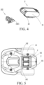
- the self-moving device 1 when the self-moving device 1 has a plurality of energy modules 2, as shown in FIG. 5 , the energy modules 2 may be accumulated and inserted in one same accommodating cavity 101.
- the structure of the accommodating cavity 101 may be adapted according to the structure of the energy module 2.
- each energy module 2 is one battery pack and each battery pack is provided with one energy module connector 22, a corresponding quantity of self-moving device connectors 102 is provided inside the accommodating cavity 101 to fit the energy module connector 22 of each battery pack.
- the self-moving device connector 102 may be, as shown in FIG. 5 and FIG.
- the self-moving device connector 102 is vertically disposed in the middle of the accommodating cavity 101.
- a plurality of self-moving device connectors 102 are correspondingly disposed.
- the self-moving device connector 102 may be disposed as movable or detachable. For example, three movable self-moving device connectors 102 are disposed in the accommodating cavity 101 in advance.
- the positions of corresponding self-moving device connectors 102 may be changed according to the sizes of the battery packs to enable each battery pack to be docked to each corresponding self-moving device connector 102. If only two battery packs need to be inserted in the accommodating cavity 101, one of the self-moving device connectors 102 may be detached or left vacant, and the positions of the two remaining self-moving device connectors 102 are changed for docking to corresponding battery packs. In this embodiment, the self-moving device connector 102 may be directly docked to the energy module connector 22.
- the electric tool 9 also includes an electric tool docking connector configured for docking to the energy module 2.
- the electric tool docking connector is also a fast-pluggable connector.
- the self-moving device connector 102 is the same as an electric tool connector, to enable the energy module 2 to be directly selectively configured to supply power to the self-moving device 1 or the electric tool 9.
- the energy modules 2 may be separately arranged.
- the energy modules 2 are arranged in different positions of the body 10 of the self-moving device 1.
- the body 10 is provided with a plurality of accommodating cavities 101 corresponding to the energy modules 2.
- Each energy module 2 is accommodated inside a corresponding accommodating cavity 101.
- the energy module connector 22 is disposed on the battery packs 21.
- the energy module 2 may be provided with one carrier.
- the carrier is provided with a plurality of inner interfaces accommodating the battery packs and an outer interface for docking to the accommodating cavity.
- the plurality of battery packs are assembled in the inner interfaces of the carrier.
- the carrier assembled with the plurality of battery packs is used as the entire energy module and is accommodated inside the accommodating cavity.
- the outer interface is provided with the energy module connector for docking to the self-moving device connector.
- a conventional wired charging technology is used to perform charging between the self-moving device 1 and the energy module 2.
- a wireless charging technology may be used to perform charging between the self-moving device 1 and the energy module 2.
- the self-moving device connector in the wired charging technical solution and the charging interface corresponding to the self-moving device in the wireless charging technical solution may be generally referred to as a self-moving device power supply interface.
- the energy module connector in the wired charging technical solution and the charging interface corresponding to the energy module in the wireless charging technology may be generally referred to as an energy module interface.
- the self-moving device connector and the energy module connector in the wired charging technical solution are both fast-pluggable connectors, to implement fast insertion of the energy module 2 into and fast detachment of the energy module 2 from the self-moving device 1.
- the self-moving device power supply interface and the energy module interface are docked in the form of a connector to complete energy transmission, or fit in the form of wireless charging to complete energy transmission, or fit in another manner to complete energy transmission.
- the self-moving device power supply interface is electrically connected to the energy module interface.
- the electric tool is also provided with an electric tool power supply interface.
- the energy module interface and the electric tool power supply interface fit in the foregoing manners to complete energy transmission.
- the energy module interface is electrically connected to the electric tool power supply interface.
- the energy module interface may be electrically connected to the electric tool power supply interface to supply power to the electric tool.
- the energy module interface may be electrically connected to the electric tool power supply interface by a connector.
- the energy module interface is the energy module connector shown in FIG. 3 to FIG. 6 .
- the electric tool power supply interface is an electric tool connector that fits and is docked to the energy module connector.
- the electric tool connector and the energy module connector may be joined by a conversion member.
- the self-moving device 1 includes a self-moving device power supply interface that is directly docked to the energy module 2.
- the electric tool 9 includes an electric tool power supply interface that is directly docked to the energy module 2.
- the self-moving device power supply interface is the same as the electric tool power supply interface, so that the energy module 2 can be directly docked to the electric tool 9 or directly docked to the self-moving device 1 without using any conversion member, to implement that the energy module 2 can be directly selectively configured to supply power to the self-moving device 1 or the electric tool 9.
- the self-moving device connector 102 includes a plurality of first terminals 1021 disposed inside the accommodating cavity 101.
- the energy module connector 22 includes a plurality of second terminals (not shown) assembled on the battery pack 21.
- the self-moving device connector 102 and the energy module connector 22 are docking connectors of each other and fit each other for docking.
- the first terminals 1021 are docked to the second terminals to complete an electrical connection.
- the self-moving device power supply interface may be different from the electric tool power supply interface, but instead a conversion member is used for conversion, to implement that the energy module is selectively configured to supply power to the self-moving device or the electric tool.
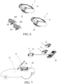
- the self-moving device connector 102 may be electrically connected to the energy module connector 22 by an interface adapter 6.
- the automatic working system further includes at least one interface adapter 6.
- the interface adapter 6 includes at least two groups of conversion interfaces. A group of conversion interfaces 61 are docked to at least one self-moving device connector 102, and another group of conversion interfaces 62 are docked to at least one energy module connector 22.
- the conversion interface 62 docked to the energy module connector 22 is the same as the electric tool power supply interface, to implement that the energy module can be selectively configured to supply power to the self-moving device 1 or the electric tool 9 by means of the conversion of a conversion interface.
- the interface adapter is not limited to the interface adapter with a cable shown in FIG. 7 , and may be another type of interface adapter.
- the interface adapter may have no cable, provided that two groups of conversion interfaces are provided.
- the interface adapter may be a converter for various types of battery packs, and different batteries can be plugged when different converters are mounted.
- the interface adapter 6 and the energy module 2 may be generally referred to as a new energy module.
- the conversion interface 61, electrically connected to the self-moving device connector 102, of the interface adapter 6 may be referred to as a new energy module connector.
- the self-moving device 1 further includes a protection apparatus 12 disposed on the body 10 and wrapping the energy module 2.
- the protection apparatus 12 is mainly configured for a water-proof purpose, a moist-proof purpose, a sun-proof purpose, and the like.
- the protection apparatus 12 may be configured for only one or more of the water-proof purpose, the moist-proof purpose, the sun-proof purpose, and the like.
- the protection apparatus 12 may be only a rain-proof cover to prevent rainwater from reaching the energy module 2, the self-moving device connector 102 on the accommodating cavity 101 or other circuits to cause circuit damage.
- the protection apparatus 12 may be assembled on the body 10. Only one end of the protection apparatus 12 may be fastened to the body 10, and the other end is not fastened. In another embodiment, both ends of the protection apparatus 12 may be fastened. For fastening manners, one end of the protection apparatus 12 is nondetachably fastened, and the other end of the protection apparatus 12 is detachably fastened, or both ends of the protection apparatus 12 are detachably fastened.
- Decorable fastening means that the protection apparatus 12 can be detached from the body 10 without a damaging act and without needing to detach a fastener such as a screw, and after being detached, the protection apparatus 12 can be fastened to the body 10 again. For example, a buckle is used.
- nondetachable fastening means that the protection apparatus 12 can be detached from the body 10 only by using a damaging act or detaching a fastener such as a screw.
- a nondetachable rotating shaft is used for fastening.
- both ends of the protection apparatus 12 may be fastened, and both ends of the protection apparatus 12 are nondetachably fastened to the body 10.
- the protection apparatus 12 and the body 10 define one accommodating cavity.
- the energy module 2 is completely accommodated inside the accommodating cavity to implement protection.
- One inlet for the energy module 2 to pass through may be kept nearby the accommodating cavity to pull out or mount the energy module 2.
- both ends of the protection apparatus 12 may be disposed on the body 10 in an unfastened manner, provided that the protection apparatus 12 can protect the accommodating cavity 101 and electrical components therein and the energy module 2.
- the energy module 2 and the protection apparatus 12 wrapping the energy module 2 may be disposed in different positions of the body 10 according to actual cases.
- the energy module 2 and the protection apparatus 12 are disposed below the body 10 to reduce environmental impact from rain, sunlight, and the like, or are disposed above the body 10 to make it convenient to mount and remove the energy module, or are disposed behind, in front of or on a side of the body 10 to reduce exposure to rain and sunlight and facilitate mounting and removal.
- the effects corresponding to different positions of the energy module 2 and the protection apparatus 12 are analyzed according to specific scenarios and cases. Only examples are provided in the foregoing.
- the energy module 2 is usually watertightly disposed below the self-moving device 1 to prevent rainwater from entering the accommodating cavity 101, so as not to damage the energy module 2 and other electrical structures in the accommodating cavity 101.
- the energy module 2 is selectively configured to supply power to another electric tool 9. If the energy module 2 is watertightly disposed below the self-moving device 1, it is not convenient for a user to rapidly fetch and mount the energy module 2, resulting in poor user experience. Therefore, it is necessary to design a self-moving device that facilitates rapid fetching and mounting of the energy module 2 by the user and has a desirable water-proof effect.
- a self-moving device 200 further includes a protection apparatus blocking a battery accommodating portion 201.
- the protection apparatus is a protective cover 230 assembled on a body 210.
- the protection apparatus may be a part of the body 210.
- the protection apparatus may be a part of the housing 3. The protection apparatus is directly formed extending outward from a part of the housing 3.
- the protection apparatus blocks the battery accommodating portion 201, to prevent rainwater from entering the battery accommodating portion 201 or sunlight from scorching the battery accommodating portion 201.
- the battery accommodating portion 201 includes an accommodating cavity 203 accommodating the energy module 2, a wall portion 204 surrounding the accommodating cavity 203, and the self-moving device connector 102 accommodated inside the accommodating cavity 203 and docked to the energy module 2.
- the energy module 2 is provided with the energy module connector 22 docked to the self-moving device connector 102.
- the accommodating cavity 203 includes an inlet 205 in communication with the outside.
- the protective cover 230 operably blocks the inlet 205. Specifically, the "operably" means that the protective cover 230 may be operated to block the inlet 205.
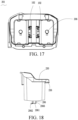
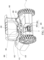
- the protective cover 230 may be assembled open on the body 210. When the protective cover 230 is not open (closed), the protective cover 230 blocks the inlet 205, to prevent rain water or sunlight from damaging a circuit inside the accommodating cavity 203 or the energy module 2. In this embodiment, the protective cover 230 completely covers the inlet. In an optimal embodiment, a seal ring may be added at the position in which the protective cover 230 is docked to the wall portion 204 to enhance sealing and improve water-proof performance. As shown in FIG. 13 , in this embodiment, an upper end surface 2040 of the wall portion 204 partially protrudes upward to form a water-proof boss 2041. The upper end surface 2040 of the wall portion 204 partially recesses downward to form a drainage groove 2042.
- An upper end and a lower end of the drainage groove 2042 are separately in communication with the outside.
- a seal ring 231 is provided in a position in which the protective cover 230 is docked to the water-proof boss 2041.
- the seal ring 231 and the water-proof boss 2041 fit to implement sealing at the position of docking.
- the indirect communication with the outside means that the drainage groove 2042 is not in direct communication with the outside, but is in communication with the outside via a third member to guide water out of the self-moving device 200.
- the drainage groove 2042 is in communication with a drainage structure (not shown) of the self-moving device 200. Water in the drainage groove 2042 is guided into the drainage structure. The drainage structure then guides the water out of the self-moving device 200.
- the water-proof boss 2041 stops the water to prevent the water from flowing into the accommodating cavity 203.
- the water flows out of the drainage groove 2042, so that the water is guided out in time to prevent the water from accumulating on the upper end surface 2040 of the wall portion 204.
- the wall portion 204 is a part of the body 210.
- the wall portion 204 is a part of the housing 3.
- the housing 3 partially recesses inward to form the wall portion 204.
- the protective cover 230 is assembled on the housing 3.
- the wall portion 204 may be separately formed and then assembled into the body.
- the protective cover 230 is assembled on the body having the wall portion 204.
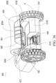
- FIG. 12 is an enlarged three-dimensional view of the battery accommodating portion 201 assembled with the protective cover 230 in the self-moving device 200.
- the protective cover 230 includes a positioning portion 232 assembled with the wall portion 204.
- the wall portion 204 is provided with a positioning hole 2043, where the positioning hole 2043 and the positioning portion 232 limit each other.
- the positioning portion 232 is accommodated inside the positioning hole 2043, and is rotatable inside the positioning hole 2043 to enable the protective cover 230 to open or close.
- left and right end surfaces of the positioning portion 232 protrude outward to form a rotating shaft.
- the rotating shaft is inserted in the positioning hole 2043 to rotate to implement opening or closing of the protective cover 230.
- specific structures of the positioning portion 232 and the positioning hole 2043 are not limited to the foregoing manner, and may be determined according to an actual case.
- the self-moving device 200 further includes a locking apparatus 250.
- the locking apparatus 250 is configured to lock the energy module 2 in the self-moving device 200.
- the locking apparatus 250 locks the protective cover 230 and the body 210 to prevent the protective cover 230 from being opened, thereby preventing the energy module 2 from being stolen.
- the locking apparatus 250 may directly lock the energy module 2 and the self-moving device 200 or lock the energy module 2 in the self-moving device 200 in another manner.
- the locking apparatus 250 may be a mechanical lock or an electrical lock.
- the electrical lock includes a password lock, a smart lock using image recognition, fingerprint recognition, voice recognition or iris recognition or the like.
- the protective cover 230 is locked at the wall portion 204.
- the locking apparatus 250 is disposed at an end opposite the positioning portion 232.
- the protective cover 230 may be locked in another position of the body 210.
- the battery accommodating portion 201 is disposed above the body 210.
- the energy module 2 is inserted in the battery accommodating portion 201 in a vertical direction.
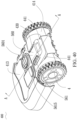
- a battery accommodating portion 201 of a self-moving device 300 is disposed behind the body 210.
- the energy module 2 is inserted in the battery accommodating portion 201 from rear to front.
- the protective cover 230 is assembled behind the body 210 and covers the inlet 205 of the battery accommodating portion 201.
- the battery accommodating portion 201 may be disposed in another position of the body 210, for example, disposed below or in front of the body 210.
- the battery accommodating portion 201 of the self-moving device 300 is disposed behind the body 210.
- the energy module 2 is inserted in the battery accommodating portion 201 from rear to front.
- the protective cover 230 is assembled behind the body 210 and covers the inlet 205 of the battery accommodating portion 201.
- the protective cover 230 includes a main cover board 235 that seals the inlet 205, a positioning portion 232 located on one side of the main cover board 235 and fastened to the body 210, and a stop wall 236 located on the other side of the main cover board 235 and formed extending from an edge of the main cover board 235.
- the body 210 is provided with a positioning hole 2043 accommodating the positioning portion 232.
- the positioning portion 232 is accommodated inside the positioning hole 2043 to rotate to implement opening or closing of the protective cover 230.
- An edge of the stop wall 236 protrudes from an edge of the wall portion 204, to prevent water from flowing into a battery groove.
- the stop wall 236 extends inward (in a direction from the protective cover 203 to the inlet 205) from an edge of the main cover board 235.
- An inner wall 2361 of the stop wall 236 is located outside an outer wall 2049 of the wall portion 204.
- the inner wall 2361 of the stop wall 236 wraps the outer wall 2049 of the wall portion 204 to seal the inlet 205, thereby preventing water from flowing into the accommodating cavity 203.
- the protective cover 230 may be designed into another structure to block the inlet of the battery accommodating portion 201 or wrap the energy module 2 to implement a water-proof purpose, a moist-proof purpose, a sun-proof purpose or the like of the energy module 2 and a corresponding circuit.
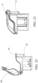
- the battery accommodating portion 201 is further provided with a water drainage apparatus 206 in communication with the accommodating cavity 203.
- the water drainage apparatus 206 includes a water accumulation groove 2066, a water leakage hole 2060, a cover board 2061 stopping the water leakage hole 2060, a rotating shaft 2063 for fastening the cover board 2061, and a bearing block 2062 fastened inside an end of the cover board 2061.
- One end of the cover board 2061 stops the water leakage hole 2060, and a bearing block 2062 is fastened at the other end of the cover board 2061.
- a rotating shaft is disposed between the two ends to fasten the cover board 2061 inside the body 210.
- one end of the bearing block 2062 of the cover board 2061 is heavier than the end that seals a drainage hole.
- the cover board 2061 that seals the water leakage hole 2060 to prevent external moist or water from entering the accommodating cavity 203.
- a plurality of magnetic components 2065 that attract each other are disposed in positions corresponding to the cover board 2061 around the water leakage hole 2060, so that as the self-moving device 200 moves, the cover board 2061 can stably seal the drainage hole, to prevent the cover board 2061 from being opened from shaking.
- the cover board 2061 rotates clockwise, the cover board 2061 that seals the water leakage hole 2060 is opened, and the accumulated water flows out through the water leakage hole 2060, to prevent the water from accumulating in the accommodating cavity 203, so as not to damage the energy module 2 or related circuits.
- the cover board 2061 is driven by the bearing block 2062 to rotate counterclockwise to seal the water leakage hole 2060.
- a plurality of water leakage holes 2067 located in the bottom of the battery accommodating portion 201 may be directly provided. The water leakage holes 2067 enable the accommodating cavity 203 to be in communication with the outside. If water is accumulated in the accommodating cavity 203, the water is directly guided outside through the water leakage holes 2067.
- the self-moving device 200 in this embodiment further includes a closing detection module 241 and a corresponding control structure.
- the self-moving device 200 includes a movement module 4, a cutting module 5, a closing detection module 241, and a control module 7.
- the closing detection module 241 is configured to detect whether the protective cover 230 and the body 210 are successfully closed to obtain a detection result.
- the control module 7 controls a working status of the self-moving device 200 according to the detection result of the closing detection module 241. Specifically, if the detection result of the closing detection module 241 is that the protective cover 230 and the body 210 are successfully closed, the self-moving device 200 is controlled to be electrified.
- the closing detection module 241 may be disposed in a position in which the protective cover 230 is docked to the body 210.
- the closing detection module 241 uses a mechanical touch manner, a sensor detection manner, a capacitor detection manner or the like to detect whether the protective cover 230 is successfully closed.
- the closing detection module 241 is only an implementation of the present invention, in other embodiments, according to an actual case, the closing detection module 241 may be disposed in another position or a different detection manner may be used for the closing detection module 241.
- the self-moving device 300 further includes a reset structure, so that when the protective cover 230 is open, the protective cover 230 can be restored to a water-proof state.
- the water-proof state is a state in which the self-moving device 300 is water-proof.
- the protective cover 230 in a second embodiment is in a closed state.
- water-proof requirements can still be satisfied when the protective cover 230 reaches an unclosed state. In this case, the foregoing unclosed state is also referred to as the water-proof state.
- the self-moving device 300 may use an automatic reset structure to automatically restore the self-moving device 300 to the water-proof state.
- a non-automatic reset structure may be used to remind a user to restore the self-moving device 300 to the water-proof state.
- the self-moving device 200 includes a pivot portion 240 configured to connect the protective cover 230 and the body 210, to enable the protective cover 230 to be rotatable around the pivot portion 240 to implement opening or closing of the protective cover 230.
- the body 210 is provided with a limit structure 32 limiting the protective cover 230, to prevent the protective cover 230 from swinging backward excessively, thereby ensuring that an angle ⁇ between a horizontal line OX and a connecting line between the gravity center M of the protective cover 230 and the rotation center O on a side of the inlet 205 is less than 90 degrees. In this case, when the protective cover 230 is open, the protective cover 230 tends to close by gravity.
- the limit structure 32 is disposed at a connection between the protective cover 230 and the body 210.
- the limit structure 32 is a protrusion structure or another stop block structure.
- the automatic reset structure may be disposed on the pivot portion, and includes an elastic apparatus 35 disposed on the pivot portion 240.
- the elastic apparatus 35 may be a compression spring, an extension spring, a leaf spring or another elastic apparatus.
- both the limit structure 32 and the elastic apparatus 35 in the two embodiments may be provided.
- the limit structure 32 and the elastic apparatus 35 are generally referred to as the automatic reset structure.
- a damping apparatus may further be added to reduce a reset speed of the automatic reset structure.
- the self-moving device 200 further includes a damping apparatus configured to reduce a reset speed of the automatic reset structure.
- the damping apparatus is disposed on the pivot portion 240.
- a damping torque generated by the damping apparatus of the protective cover 230 is less than a gravitational torque generated from the gravity of the protective cover 230.
- the damping torque generated by the damping apparatus is less than an elastic torque generated when the elastic apparatus 35 is compressed.
- the self-moving device 300 further includes a water-proof state detection module 31.
- the water-proof state detection module 31 is configured to detect whether the protective cover 230 and the body 210 are in the water-proof state and obtain a detection result.
- the self-moving device 300 is controlled according to the detection result to restore the water-proof state.
- the self-moving device 300 is controlled according to the detection result to restore the water-proof state in two manners.
- One manner is automatic control. That is, the self-moving device 1 is automatically controlled to restore the water-proof state.
- the other manner is non-automatic control. For example, a user is reminded that the self-moving device 1 is not in the water-proof state.
- the water-proof state is that the protective cover 230 is in a closed state.
- the water-proof state detection module 31 is configured to detect whether the protective cover 230 is closed. In other embodiments, the water-proof state may be that the protective cover 230 is in an unclosed state. A specific state is determined according to an actual case. In this embodiment, the water-proof state detection module 31 is configured to detect whether the protective cover 230 is closed.
- the self-moving device 300 is controlled according to the detection result to restore the protective cover 230 to a closed state. There are specifically two restoration manners. In one manner, the protective cover 230 is automatically controlled according to the detection result to close.
- the protective cover 230 is automatically controlled in an electric manner or another manner to close. In the other manner, the user is reminded according to the detection result that the protective cover 230 is not closed.
- the water-proof state detection module is provided with an indicator lamp or another display structure or a sound alarm or another alarm structure, configured to display a closed case of the protective cover 230.
- the indicator lamp flashes to send alarm information or a sound alarm is raised to remind the user to close the protective cover 230, to restore the protective cover 230 to the water-proof state.
- the water-proof state detection module 31 may be disposed in a position in which the protective cover 230 is docked to the body 210.
- the water-proof state detection module 31 uses a mechanical touch manner, a sensor detection manner, a capacitor detection manner or the like to detect whether the protective cover 230 is successfully closed.
- the water-proof state detection module 31 is only an implementation of the present invention. In other embodiments, according to an actual case, the water-proof state detection module 31 may be disposed in another position or a different detection manner may be used for the water-proof state detection module 31.
- the water-proof state detection module 31 may be referred to as a non-automatic reset structure.
- the self-moving device 300 includes a control module 7.
- the control module 7 controls a working status of the self-moving device 300 according to the detection result of the water-proof state detection module 31. Specifically, if the detection result of the water-proof state detection module 31 is that the protective cover 230 and the body 210 are successfully closed, the self-moving device 300 is controlled to be electrified. If the detection result of the water-proof state detection module 31 is that the protective cover 230 and the body 210 are successfully closed, the self-moving device 300 is controlled to be not electrified.
- the automatic reset structure and the non-automatic reset structure in the foregoing embodiment both directly restore the self-moving device 300 to the water-proof state or indirectly provide a reminder to make the user restore the self-moving device 300 to the water-proof state. Both structures are used to restore the self-moving device 300 to the water-proof state, and may be generally referred to as a reset structure.
- the limit structure 32, the elastic apparatus 35, and the water-proof state detection module 31 may be generally referred to as a reset structure.
- a structure with either automatic or non-automatic implementation can be generally referred to as a reset structure provided that the self-moving device 300 is restored to the water-proof state.
- a self-moving device 400 further includes a drainage system configured to drain water to prevent water from entering an accommodating cavity 420.
- a drainage system configured to drain water to prevent water from entering the accommodating cavity 420 is added to the self-moving device 400 in this embodiment.
- the remaining structures are all the same as those in the foregoing embodiments or can be combined with the foregoing embodiments. Details are not described one by one again herein.
- the self-moving device 400 includes a body 410, a movement module 4 configured to drive the self-moving device 400 to move, a task execution module configured to perform a work task, and a control module 7 configured to control the self-moving device 400 to move and walk inside a defined working area.
- the movement module 4 and the control module 7 are disposed on the body 410.
- the control module 7 controls the movement module 4 to drive the self-moving device 400 to move inside the defined working area, and at the same time controls the task execution module to perform the work task inside the defined working area.
- the self-moving device 400 is an automatic mower.
- the task execution module of the self-moving device 400 is a cutting module 5.
- the self-moving device 400 may be an automatic leaf blower, an automatic water sprinkler, a multifunctional machine, an automatic snowplow, a robot cleaner or the like.
- the task execution module of the self-moving device 400 is a task execution module that performs a corresponding work task.
- the self-moving device 400 is an automatic snowplow
- the task execution module of the self-moving device 400 is a snow removal module.
- the automatic working system 100 further includes an energy module 2 configured to supply power to the self-moving device 400.
- the energy module 2 may selectively supply power to the self-moving device 400 or supply power to another electric device.
- the another electric device is an electric device other than the self-moving device 400, for example, an electric tool or a home appliance.
- the energy module 2 may selectively supply power to the self-moving device 400 or another electric tool.
- the another electric tool is an electric tool other than the self-moving device 400, and is, for example, a gun drill, a hammer drill, a trimmer or a hand-propelled lawnmower.
- the self-moving device 400 is powered by the detachable energy module 2.
- the detachable energy module is a detachable battery pack that supplies power to an electric tool such as a gun drill, a hammer drill, a trimmer or a hand-propelled lawnmower.
- the detachable energy module means that the energy module 2 is detachably assembled on the body 410.
- “Detachably” means that the energy module 2 can be directly detached without needing to remove a fastener such as a screw, a nut or a pin.
- the energy module 2 is docked to the self-moving device 400 by a connector, a wireless charging interface or the like, so that the energy module 2 and the self-moving device 400 are conveniently undocked, to implement fast insertion.
- a protective cover or the like fastened to the body 410 may be disposed outside the energy module 2, or even the protective cover and the body are fastened by a fastener such as a screw, a nut or a pin.
- the energy module 2 is "detachable" provided that fast insertion of the energy module 2 in the self-moving device 400 can be implemented.
- the self-moving device 400 includes an accommodating cavity 401 configured to accommodate the energy module 2.
- the accommodating cavity 401 is provided with an inlet 405 to enable the energy module 2 to be inserted or pulled out.
- the self-moving device 400 further includes a protective cover 430 configured to operably block the inlet 405 to prevent water from entering the accommodating cavity 401 and a drainage system 420 configured to drain water to prevent water from entering the accommodating cavity 401.
- the drainage system 420 includes a drainage groove 421 in communication with the outside of the self-moving device 400 to drain water outside.
- the body 410 includes a bearing portion 411 configured to bear the circumference of the protective cover 430.
- the drainage groove 421 is provided in the bearing portion 411 to prevent water from flowing into the accommodating cavity 401 through a joint between the protective cover 430 and the body 410.
- the bearing portion 411 includes a joint area, joined to the protective cover 430, on the body 410, and an area located near the joint area.
- the self-moving device 400 further includes a pivot portion 440 configured to connect the protective cover 430 and the body 410.
- the protective cover 430 is movable around the pivot portion 440 to implement opening or closing of the protective cover 430.
- the protective cover 430 is rotatable around the pivot portion 440 to implement opening or closing of the protective cover 430.
- the body 410 includes a pivot groove 450 accommodating the pivot portion 440.
- the pivot portion 440 includes a protective cover connecting end 441 connected to the protective cover 430 and a body connecting end 442 connected to the body 410.
- the body connecting end 442 is accommodated inside the pivot groove 450.
- the pivot portion 440 around the body connecting portion 441 rotates inward, and the part such as the protective cover connecting end 441 of the pivot portion 440 exposed from the pivot groove 450 is accommodated inside the pivot groove 450 along with the rotation, to ensure a smooth transition at a connection between the protective cover 430 and the body 410 in a travel direction of the self-moving device 400.
- FIG. 37 there is only a slit at the connection between the body 410 and the protective cover 430.
- the connection between the body 410 and the protective cover 430 has a smooth transition, so that the self-moving device 400 has desirable overall appearance.
- a specific structure of the pivot portion 440 may be set according to an actual case. Details are not listed one by one herein.
- the drainage groove 421 includes a pivot portion drainage groove 422 in communication with the pivot groove 450.
- the pivot portion drainage groove 422 includes a drainage hole 4221 in communication with the outside and a connecting groove 4222 connecting the pivot groove 450 and the drainage hole 4221.
- the drainage hole 4221 is located below the connecting groove 4222, to enable water to flow into the drainage hole 4221 from top to bottom from the connecting groove 4222 to flow out of the drainage hole 4221.
- the drainage groove 421 divides the body 410 into a front portion and a rear portion.
- the body 410 includes a front body portion 413 located in front of the drainage groove 421 and a rear body portion 414 located behind the drainage groove 421.
- the drainage groove 421 further includes a water leakage hole 425 disposed at the bottom of the accommodating cavity 401 and configured to enable the accommodating cavity 401 to be in communication with the outside of the self-moving device 400.
- a water-stop dust-proof apparatus such as a sponge may be disposed on the water leakage hole 425, so that water inside the self-moving device 400 can flow out, and external dust and water can be stopped from entering the self-moving device 400.
- left and right ends of the drainage groove 421 are respectively in communication with left and right side walls 4141 of the body 410. That is, the left and right ends of the drainage groove 421 are in communication with the outside of the self-moving device 400, to enable water in the drainage groove 421 to flow out through the drainage hole 4221 and flow out from the left and right ends of the drainage groove 421.
- the drainage groove 421 is defined by a front inner wall 4134 located at the front body portion 413, a rear inner wall 4144 located at the rear body portion 414, and a bottom inner wall 4145 connecting the front inner wall 4134 and the rear inner wall 4144.
- the bottom inner wall 4145 is lower than the front inner wall 4134 and the rear inner wall 4144.
- An upper surface of the rear inner wall 4144 is higher than the highest position of the inlet 405, to prevent water in the drainage groove 421 from flowing into the inlet 405.
- the protective cover 430 covers an upper surface of the rear body portion 414.
- a projection of the protective cover 430 in a horizontal direction is larger than a projection of a corresponding position of the body 410 in the horizontal direction.
- a projection of the protective cover 430 in a transverse direction is larger than a projection of an upper surface of the corresponding position of the body 410 in the transverse direction.
- the transverse direction is the transverse direction of the protective cover 430 or the transverse direction of the body 410.
- the protective cover 430 includes a top cover 4304, a lateral protective wall 4301 extending from the top cover 4304 toward the left and right sides, and a rear protective wall 4303 formed extending backward from the top cover 4304.
- the lateral protective wall 4301 is located on an outer side of the left and right side walls 4141 of the rear body portion 414.
- the rear protective wall 4303 is located on an outer side of a rear wall 4143 of the rear body portion 414.
- the bottom of the lateral protective wall 4301 is lower than an upper surface 4142 of the left and right side walls 4141 of the rear body portion 414, to guide out water from the lateral protective wall 4301 of the protective cover 430, thereby preventing water from flowing into the accommodating cavity 401 from the left and right sides of the protective cover 430.
- the circumference of the rear body portion 414 fits the protective cover 430.
- the circumference of the rear body portion 414 may be considered as the bearing portion 411 located on the body 410 and configured to bear the circumference of the protective cover 430.
- the inlet 405 of the accommodating cavity 401 is formed recessing inward from the rear wall 4143 of the rear body portion 414, to make it convenient for the user to fetch or mount the energy module 2 in a longitudinal direction.
- the rear protective wall 4303 covers the outer side of the inlet 405. The bottom of the rear protective wall 4303 is lower than the lowest end of the inlet 405, to prevent water from entering the accommodating cavity 401 through the inlet 405.
- the inlet 405 includes a vertical opening 4051 extending in a vertical direction and a longitudinal opening 4052 extending in a longitudinal direction.
- the inlet 405 directly includes the vertical opening 4051 extending in the vertical direction and the longitudinal opening 4052 extending in the longitudinal direction that are in communication with each other.
- the inlet 405 is oblique, and the inlet 405 includes an upper end edge 4055 and a lower end edge 4056.
- the inlet 405 includes a component extending in the vertical direction and a component extending in the longitudinal direction.
- the component extending in the vertical direction of the inlet 405 is the vertical opening 4051 extending in the vertical direction
- the component extending in the longitudinal direction is the longitudinal opening 4052 extending in the longitudinal direction.
- the inlet 405 includes the vertical opening 4051 extending in the vertical direction to enable the user to remove or mount the energy module 2 in the longitudinal direction.
- the longitudinal opening 4052 extending in the longitudinal direction provides a larger movement space during operation of the user, in particular, provides the user with a movement space in the longitudinal direction during operation, so that the user can insert the energy module 2 more conveniently.
- the rear protective wall 4303 includes an operation portion 4306. The user applies a force to the operation portion 4306 to open and close the protective cover 430. In an embodiment, the rear protective wall 4303 tilts outward and extends downward.
- the operation portion 4306 is disposed on the rear protective wall 4303 that tilts outward and extends downward, so that in one aspect, water flows out of the protective cover 430 along an oblique surface, and in another aspect, the rear protective wall 4303 that tilts outward makes it easier for the user to apply a force to the operation portion 4306, thereby further facilitating the operations when the user opens the protective cover 430.
- the protective cover 430 only covers a part of the rear body portion 414.
- a projection of the protective cover 430 in a horizontal direction is smaller than a projection of a corresponding position of the body 410 in the horizontal direction.
- a projection of the protective cover 430 in a transverse direction is smaller than a projection of an upper surface of the corresponding position of the body 410 in the transverse direction.
- the self-moving device 400 includes a pivot portion 440 configured to connect the protective cover 430 and the body 410.
- the protective cover 430 is movable around the pivot portion 440 to implement opening or closing of the protective cover 430.
- the protective cover 430 is rotatable around the pivot portion 440 to implement opening or closing of the protective cover 430.
- the body 410 includes a pivot groove 450 accommodating the pivot portion 440.
- the drainage system 420 includes a drainage groove 421 in communication with the outside of the self-moving device 400 to drain water outside.
- the body 410 includes a bearing portion 411 configured to bear the circumference of the protective cover 430.
- the drainage groove 421 is provided in the bearing portion 411, to prevent water from entering the accommodating cavity 401 through a joint area in which the protective cover 430 is joined to the body 410.
- the drainage groove 421 includes a pivot portion drainage groove 422 in communication with the pivot groove 450.
- the pivot portion drainage groove 422 includes a drainage hole 4221 in communication with the outside and a connecting groove 4222 connecting the pivot groove 450 and the drainage hole 4221.
- the drainage hole 4221 is located below the connecting groove 4222, to enable water to flow into the drainage hole 4221 from top to bottom from the connecting groove 4222 to flow out of the drainage hole 4221.
- the drainage groove 421 divides the body 410 into a front portion and a rear portion.
- the body 410 includes a front body portion 413 located in front of the drainage groove 421 and a rear body portion 414 located behind the drainage groove 421.
- the structure of the pivot portion drainage groove 422 is basically the same as the structure shown in embodiments in FIG. 35 to FIG. 39 .
- a difference only lies in that the left and right ends of the pivot portion drainage groove 422 are not in communication with the rear body portion 414.
- the length of the pivot portion drainage groove 422 in the transverse direction is less than the length of the corresponding position of the body 410 in the transverse direction.
- the transverse direction is a width direction of the self-moving device 400, that is, a direction perpendicular to the travel direction of the self-moving device 400. As shown in FIG.
- the drainage groove 421 further includes a water leakage hole 425 disposed at the bottom of the accommodating cavity 401 and configured to enable the accommodating cavity 401 to be in communication with the outside of the self-moving device 400.
- a water-stop dust-proof apparatus such as a sponge may be disposed on the water leakage hole 425, so that water inside the self-moving device 400 can flow out, and external dust and water can be stopped from entering the self-moving device 400.
- the drainage system 420 further includes a water guide groove 423 disposed on the surface of the body 410 and provided with a bottom.
- the water guide groove 423 is formed recessing inward from a part of the rear body portion 414.
- the water guide groove 423 is provided in the bearing portion 411, to guide water at a joint between the protective cover 430 and the body 410 out of the body 410.
- the water guide groove 423 is located on two sides of the accommodating cavity 401.
- the body 410 includes a separating wall 5641 disposed between the water guide groove 423 and the accommodating cavity 401.
- the separating wall 5641 separates the water guide groove 423 from the accommodating cavity 401, to prevent water in the water guide groove 423 from flowing into the accommodating cavity 401.
- the water guide groove 423 includes a water guide passage 4232 formed recessing inward from the surface of the body and a water guide hole 4231 that enables the water guide passage 4232 to be in communication with the outside of the self-moving device 400. When water passes through the surface of the self-moving device 400, the water may flow into the water guide hole 4231 along the water guide passage 4232 to flow out of the self-moving device 400.
- the protective cover 430 includes a top cover 4304, a lateral protective wall 4301 extending from the top cover 4301 toward the left and right sides, and a rear protective wall 4303 formed extending backward from the top cover 4301.
- the rear body portion 414 includes a side wall accommodating groove 4144 accommodating the lateral protective wall 4304.
- the water guide groove 423 is in communication with the side wall accommodating groove 4144, to enable water flowing down along the lateral protective wall 4304 to flow into the water guide groove 423, so that the water is further guided out of the self-moving device 400 by the water guide groove 423.
- the bottom of the water guide groove 423 extends to the outside of the body 410 from the middle of the body 410.
- the bottom of the water guide groove 423 extends from top to bottom, so that the water guide groove 423 automatically guides out water from inside.
- the drainage system 420 further includes a water-stop wall 424 located in front of the inlet 405 to stop water from entering the inlet 405.
- the water-stop wall 424 is disposed between a lower thermal insulation body 5602 and the protective cover 430.
- the water-stop wall 424 includes a plurality of lower water-stop walls 4241 formed protruding outward from an upper surface of the lower thermal insulation body 5602 and a plurality of upper water-stop walls 4242 extending from a lower end of the protective cover 430.
- the water-stop wall 424 extends in a transverse direction.
- the transverse direction is a width direction of the self-moving device 400, that is, a travel direction perpendicular to the self-moving device 400.
- the water-stop wall 424 extending in the transverse direction includes the water-stop wall 424 extending in parallel to a width direction, that is, the water-stop wall 424 completely extends in the transverse direction, and also includes the water-stop wall 424 having a component extending in the transverse direction.
- the water-stop wall 424 extending in the transverse direction is disposed, and an outer edge of the water-stop wall 424 protrudes outward from a corresponding position of the inlet 405, so that when water flows from the middle of the body to the outside of the body, that is, when water flows from front to rear in the travel direction of the self-moving device 400, the water is blocked by a plurality of water-stop walls 424. Every water-stop wall 424 somewhat reduces a flow speed and a flow amount of water. When more water-stop walls 424 are disposed, the flow speed and flow amount of water become smaller.
- a water-stop wall at an inlet may be disposed near the inlet 405.
- the water-stop wall is formed protruding upward from a preset distance in front of the inlet 405.
- the water-stop wall 424 is directly formed protruding upward from the circumference of the inlet 405, and a plurality of front water-stop walls are disposed in front of the water-stop wall at an inlet to reduce a water flow.
- the water-stop wall 424 may be disposed on a side, near the inlet 405, of the pivot portion drainage groove 422.
- the water-stop wall 424 may be disposed in another position between the inlet 405 and the pivot portion drainage groove 422 according to an actual case, provided that a barrier can be established in front of the inlet 405 to stop water to prevent water from flowing into the inlet 405.
- the protective cover 430 configured to operably block the inlet 405 to prevent water from entering the accommodating cavity 401 and the drainage system 420 configured to drain water to prevent water from entering the accommodating cavity 401 are added, to prevent water from entering the accommodating cavity 401.
- water can be discharged to prevent water from entering the accommodating cavity.
- the seal ring may further be added at a position where the protective cover 430 fits the inlet 405, to further enhance water-proof and dust-proof effects by using a seal.
- the drainage system 420 is added to discharge water from the drainage system 420 in advance, to effectively prevent a large amount of water from accumulating around the inlet 405, thereby preventing water from permeating into the accommodating cavity 401, so as not to damage the energy module 2 and other electrical components in the accommodating cavity 401.
- the self-moving device 200 further includes a detection module and a corresponding control structure. As shown in FIG. 25 to FIG. 29 , the self-moving device 200 further includes a detection module configured to detect one or two of the temperature or humidity of the energy module 2 and a control module. The detection module detects one or two of the temperature or humidity of the energy module 2, to obtain a detection result. The control module controls a working status of the self-moving device according to the detection result. The detecting the temperature or humidity of the energy module includes directly detecting or indirectly detecting the temperature or humidity of the energy module 2.
- the drying apparatus When the humidity detected by the humidity detection module exceeds the humidity threshold, the drying apparatus dries the energy module 2 and the environment in which the energy module 2 is located to reduce humidity.
- the temperature detection module 244 and the corresponding control structure thereof when the temperature detection module 244 and the corresponding control structure thereof are added, in one aspect, it may be automatically detected whether water enters the energy module 2 and the environment in which the energy module 2 is located to make the humidity exceed the humidity threshold, and in another aspect, when it is detected that the humidity exceeds the humidity threshold, the drying apparatus may further be used to dry the energy module 2 and the environment in which the energy module 2 is located, to reduce the humidity, thereby further enhancing a water-proof effect.
- the self-moving device 200 further includes a temperature protection apparatus 245 configured to perform temperature protection on the energy module in the self-moving device 200 and the environment in which the energy module is located. Because the self-moving device 200 is in an outdoor working environment, the temperature of the energy module 2 may rapidly increase under sunlight. If the temperature is excessively high, the energy module 2 or the self-moving device 200 may be damaged. Therefore, the energy module 2 is usually sealed at the bottom of the self-moving device 200 to reduce the impact of sunlight on the energy module 2, thereby preventing the temperature of the energy module 2 from rapidly increasing. Next, in this embodiment, the energy module 2 is selectively configured to supply power to another electric tool.
- the temperature protection apparatus that performs temperature protection on the energy module 2 and the environment in which the energy module 2 is located is added, thereby reducing the impact of outdoor sunlight on the energy module 2, to avoid cases such as that the energy module 2 does not work at a high temperature or even the energy module 2 or the self-moving device 200 is damaged at a high temperature.
- the temperature protection may be active protection.
- a thermal insulation structure is added to directly reduce the impact of the sun on the energy module 2.
- the temperature protection may be passive protection.
- the temperature of the energy module 2 and the temperature in the environment in which the energy module 2 is located are adjusted, or a discharging speed of the energy module 2 is adjusted, or the status of the energy module 2 is directly controlled or the status of the self-moving device 200 is controlled.
- specific manners of active protection and passive protection are not limited to the foregoing manners. The foregoing manners are only examples. In other embodiments, other manners may be used to perform temperature protection.
- the self-moving device 200 may implement passive temperature protection by using the following specific implementation.
- the temperature protection apparatus 245 may use a mechanical structure to adjust the temperature of the energy module 2 to perform temperature protection.
- the temperature protection apparatus 245 includes a temperature adjustment apparatus 2430 configured to adjust the temperature of the energy module 2 or the environment in which the energy module 2 is located.
- the temperature adjustment apparatus 2430 is disposed in the accommodating cavity 203, to adjust the temperature in the accommodating cavity 203 to adjust the temperature of the energy module 2 and the temperature in the environment in which the energy module 2 is located.
- the temperature adjustment apparatus is a fan 2431.
- the self-moving device 200 further includes the fan 2431 disposed in the accommodating cavity 203.
- the fan may be used to cool the accommodating cavity 203 to reduce the temperature of the energy module 2 and the temperature in the environment in which the energy module 2 is located.
- the temperature adjustment apparatus 2430 may further include a heat dissipation hole 2432 added in the wall portion 204 to accelerate heat dissipation.
- the fan 2431 is used to implement forced convection of air
- the heat dissipation hole is used to implement convection between air inside the accommodating cavity 201 and ambient air, to implement heat dissipation.
- a passage for the convention between the air inside the accommodating cavity 203 and the ambient air may also be referred to as an air duct.
- the heat dissipation hole may also be referred to as an air duct opening.
- the fan is disposed in any position near the air duct, for example, disposed near the air duct opening.
- a projection of a working area that is formed through the rotation of blades of the fan on the energy module 2 covers the energy module 2.
- the fan may blow air right toward the energy module 2 to accelerate heat dissipation of the energy module 2.
- a wind guide passage configured to guide wind is provided between the fan and the energy module 2.
- the wind guide passage is formed by a plurality of wind guide boards that are disposed in the accommodating cavity 203.
- the self-moving device 200 further includes a heat dissipation motor configured to drive the fan.
- the heat dissipation motor is controlled by the control module 7 to work.
- the fan may be driven by the walking motor or the cutting motor to work instead of separately arranging the heat dissipation motor.
- the temperature adjustment apparatus may be another cooling material such as a phase change material or a semiconductor cooling sheet.
- the cooling material is used to cool the accommodating cavity 203, to reduce the temperature of the energy module 2 and the temperature in the environment in which the energy module 2 is located.
- the temperature adjustment apparatus 2430 may be another heating material such as a heating sheet. The heating sheet is heated to rapidly increase the temperature of the energy module 2 and the temperature in the environment in which the energy module 2 is located.
- the temperature protection apparatus 245 may further use an automatic control manner to implement temperature protection.
- the automatic control manner is used to adjust the temperature of the energy module 2 and the temperature in the environment in which the energy module 2 is located, or the status of the self-moving device 200 is automatically controlled to protect the energy module 2 or the self-moving device 200 from damage due to a high temperature to implement temperature protection.
- a manner of using automatic control to implement temperature protection includes completely using automatic control to implement temperature protection, combining automatic control and a mechanical structure manner to implement temperature protection, and the like.
- the temperature protection apparatus 245 further includes a temperature detection module and a corresponding control structure. As shown in FIG.
- the self-moving device 200 further includes a temperature detection module configured to detect the temperature of the energy module 2 and a control module.
- the temperature detection module detects the temperature of the energy module 2 to obtain a detection result.
- the control module controls a working status of the self-moving device according to the detection result.
- the detecting the temperature of the energy module includes directly detecting or indirect detecting the temperature of the energy module 2.
- the indirect detecting the temperature of the energy module 2 is detecting a parameter related to the temperature of the energy module 2, for example, detecting the temperature in the environment in which the energy module 2 is located, or detecting the temperature in the accommodating cavity 203 accommodating the energy module 2, to obtain the temperature in the working environment of the energy module 2, or detecting the temperature of a structure or in a specific position near the energy module 2.
- the working status of the self-moving device includes whether the self-moving device is turned on, a status of the self-moving device after being turned on, whether the self-moving device is working, the working status of the self-mov
- the temperature protection apparatus 245 further includes a temperature adjustment apparatus 2430.
- the control module controls the temperature adjustment apparatus 2430 according to a temperature detected by the temperature detection module to adjust the temperature of the energy module.
- the temperature adjustment apparatus 2430 adjusting the temperature of the energy module 2 includes directly adjusting the temperature of the energy module 2 and indirectly adjusting the temperature of the energy module 2.
- the indirectly adjusting the temperature of the energy module 2 includes adjusting the temperature in the environment in which the energy module 2 is located to indirectly adjust the temperature of the energy module 2.
- a temperature range is preset, and when a temperature detection module 243 detects that the temperature exceeds the temperature range, the temperature adjustment apparatus 2430 is started.
- the temperature range includes a cooling threshold and a heating threshold.
- the cooling threshold is greater than the heating threshold.
- the control module 7 controls the temperature adjustment apparatus 2430 to reduce the energy module 2 or the temperature in the environment in which the energy module 2 is located.
- the control module 7 controls the temperature adjustment apparatus 2430 to increase the energy module 2 or the temperature in the environment in which the energy module 2 is located.
- the temperature adjustment apparatus is a fan 2431.
- the self-moving device presets the cooling threshold.
- the control module controls the fan to be started to cool the energy module 2 and the environment in which the energy module 2 is located.
- the heat dissipation hole 2432 may be added to the wall portion 204 to accelerate heat dissipation.
- the temperature adjustment apparatus 2430 may be another cooling material such as a phase change material or a semiconductor cooling sheet.
- the control module controls the cooling material to perform cooling to reduce the temperature of the energy module 2 and the temperature in the environment in which the energy module 2 is located.
- the temperature adjustment apparatus 2430 may be another heating material such as a heating sheet.
- the control module controls the self-moving device to heat the heating sheet, to rapidly increase the temperature of the energy module 2 and the temperature in the environment in which the energy module 2 is located.
- the status of the self-moving device 200 may be automatically controlled to avoid damage to the energy module 2 or the self-moving device 200 due to a high temperature.
- the self-moving device 200 includes a charging mode and a standby mode. In the charging mode, the self-moving device 200 is docked to the charging station to perform charging.
- the charging mode includes an automatic-return charging mode and a non-automatic-return charging mode. In the automatic-return charging mode, the self-moving device 200 automatically returns to the charging station and is docked to the charging station to perform charging.
- an electric power threshold may be preset.
- the self-moving device 200 When it is detected that the electric power in the energy module 2 is less than the electric power threshold, the self-moving device 200 automatically returns to perform charging. In the non-automatic-return charging mode, the self-moving device 200 non-automatically returns to the charging station and is docked to the charging station to perform charging. Specifically, for example, a user uses a button or a remote control to control the self-moving device 200 to return to perform charging or takes the self-moving device 200 back to the charging station to dock the self-moving device 200 to the charging station to perform charging. As shown in FIG. 26 , the self-moving device 200 presets a standby temperature threshold.
- the control module 7 controls the self-moving device 200 to enter the standby mode.
- the standby mode the self-moving device 200 stops charging, and the control module 7 turns off some components in the self-moving device 200.
- the energy module 2 does not supply power to some components in the self-moving device 200.
- the energy module 2 may supply power to only the smallest micro control unit but stops supplying power to various sensors and the like.
- the self-moving device 200 normally works, the discharging current of the energy module 2 is 100 mA.
- the energy module 2 When the energy module 2 is in a standby state, the energy module 2 stops supplying power to structures other than the smallest micro control unit, so that the discharging current of the energy module 2 is 10 mA. In one aspect, in the standby mode, the energy module 2 keeps supplying power to the smallest micro control unit, so that the self-moving device 200 still keeps some functions to perform some tasks. For example, when the temperature of the energy module 2 drops within the preset temperature range, the self-moving device 200 may be automatically woken up to restart the normal working mode. In another aspect, a discharging speed of the energy module 2 is reduced when the energy module 2 is not charged, thereby reducing the risk of damage to the energy module 2 due to excessive discharge.
- the foregoing two technical solutions of using automatic control to perform temperature protection that is, the solution in which the self-moving device 200 is controlled to enter the standby mode when the temperature of the energy module 2 exceeds the standby temperature threshold and the technical solution in which the self-moving device 200 is controlled to start the temperature adjustment apparatus when the temperature of the energy module 2 exceeds the temperature range may be combined with each other or may be separately implemented.
- the temperature adjustment apparatus may be used to cool the energy module 2 and the environment in which the energy module 2 is located, to reduce the temperature below the standby threshold, and the self-moving device 200 is then woken up, so that the self-moving device 200 continues to work in a normal working mode.
- the self-moving device is a robotic lawnmower.
- the self-moving device may be an automatic leaf blower, an automatic water sprinkler, a multifunctional machine, an automatic snowplow, a robot cleaner or the like.
- the self-moving device 400 is an automatic snowplow.
- the self-moving device 400 includes a housing 3, a movement module 4, a snow removal module, a control module 7, and the like.
- reference may be made to a robotic lawnmower design.
- the temperature adjustment apparatus 2430 may be disposed as a heating material according to an actual case.
- the temperature adjustment apparatus 2430 is automatically heated until the temperature of the energy module 2 is increased to enter the preset temperature range.
- the control module controls the energy module 2 to supply power, and the automatic snowplow starts to perform work.
- a self-moving device 500 in addition to the foregoing passive protection manner to implement temperature protection, may use an active manner to implement temperature protection.
- a self-moving device 500 includes a temperature protection apparatus 245.
- the temperature protection apparatus 245 includes a thermal insulation body 560 located above a protective cover 530 and/or located between the protective cover 530 and an accommodating cavity 501.
- a difference between this embodiment and the foregoing embodiment lies in that the thermal insulation body 560 is added.
- Other structures are the same as those in the foregoing embodiments. Details are not described one by one again herein.
- the self-moving device 500 includes a body 510, a movement module 4 configured to drive the self-moving device 500 to move, a task execution module configured to perform a work task, and a control module 7 configured to control the self-moving device 500 to move and walk inside a defined working area.
- the movement module 4 and the control module 7 are disposed on the body 510.
- the control module 7 controls the movement module 4 to drive the self-moving device 500 to move inside the defined working area, and at the same time controls the task execution module to perform the work task inside the defined working area.
- the self-moving device 500 is an automatic mower.
- the task execution module of the automatic mower is a cutting module 5.
- the self-moving device 500 may be an automatic leaf blower, an automatic water sprinkler, a multifunctional machine, an automatic snowplow, a robot cleaner or the like.
- the task execution module of the self-moving device 500 is a task execution module that performs a corresponding work task.
- the self-moving device 500 is an automatic snowplow
- the task execution module of the self-moving device 500 is a snow removal module.
- the automatic working system 100 further includes an energy module 2 configured to supply power to the self-moving device 500.
- the energy module 2 may selectively supply power to the self-moving device 500 or supply power to another electric device.
- the another electric device is an electric device other than the self-moving device 500, and is, for example, an electric tool, a home appliance or the like.
- the energy module 2 may selectively supply power to the self-moving device 500 or another electric tool.
- the another electric tool is an electric tool other than the self-moving device 500, and is, for example, a gun drill, a hammer drill, a trimmer or a hand-propelled lawnmower.
- the self-moving device 500 is powered by the detachable energy module 2.
- the detachable energy module is a detachable battery pack that supplies power to an electric tool such as a gun drill, a hammer drill, a trimmer or a hand-propelled lawnmower.
- the detachable energy module means that the energy module 2 is detachably assembled on the body 510.
- "Detachably" means that the energy module 2 can be directly detached without needing to remove a fastener such as a screw, a nut or a pin.
- the energy module 2 is docked to the self-moving device 500 by a connector, a wireless charging interface or the like, so that the energy module 2 and the self-moving device 500 are conveniently undocked, to implement fast insertion.
- a protective cover or the like fastened to the body 510 may be disposed outside the energy module 2, or even the protective cover and the body are fastened by a fastener such as a screw, a nut or a pin.
- the energy module 2 is "detachable" provided that fast insertion of the energy module 2 in the self-moving device 500 can be implemented.
- the self-moving device 500 includes an accommodating cavity 501 configured to accommodate the energy module 2.
- the accommodating cavity 501 is provided with an inlet 505 to make it convenient to insert or pull out the energy module 2.
- the thermal insulation body 560 is disposed above the protective cover 530 and/or is disposed between the protective cover 530 and the accommodating cavity 501.
- a thermal insulation space 561 is provided between the thermal insulation body 560 and the protective cover 530, to improve a thermal insulation effect.
- the thermal insulation space 561 is a space located between the thermal insulation body 560 and the protective cover 530.
- the thermal insulation space 561 is added between the thermal insulation body 560 and the protective cover 530, so that the accommodating cavity 501 is provided with two layers of a thermal insulation substance, that is, the thermal insulation body 560 and the protective cover 530, disposed at an interval.
- the thermal insulation space 561 is used to increase the height of the protective cover 530, so that the distance between the protective cover 530 that is directly exposed to the sun and the accommodating cavity 501 is increased, thereby reducing the impact of sunlight on the accommodating cavity 501.
- the thermal insulation body 560 is added after the protective cover 530 and the accommodating cavity 501 are separated by the thermal insulation space 561, the thermal insulation body 560 is added.
- the protective cover 530 is used to block sunlight, to enable the thermal insulation body 560 to perform secondary thermal transfer, to prevent the direct impact of the sun on the thermal insulation body 560 closest to the accommodating cavity 501, thereby greatly improving a thermal insulation effect.
- the thermal insulation space 561 is used to increase the height of the thermal insulation body 560, so that the distance between the thermal insulation body 560 that is directly exposed to the sun and the accommodating cavity 501 is increased, thereby reducing the impact of sunlight on the accommodating cavity 501.
- the thermal insulation body 560 is used to block sunlight, to enable the protective cover 530 to perform the secondary thermal transfer, to prevent the direct impact of the sun on the protective cover 530 closest to the accommodating cavity 501, thereby greatly improving a thermal insulation effect.
- this embodiment also has advantages of saving materials, reducing manufacturing costs, reducing the weight of the entire device, and the like.
- the thermal insulation body 560 and the protective cover 530 are disposed together to form an upper cover 56.
- the upper cover 56 includes a pivot portion 540 connected to the body 510 to enable the upper cover 56 to be rotatable around the pivot portion 540 to implement opening or closing.
- the thermal insulation body 560 and the protective cover 530 may be integrally formed into one overall upper cover 56 provided with the thermal insulation space 561.
- the thermal insulation body 560 and the protective cover 530 may be separately formed, and the thermal insulation body 560 and the protective cover 530 are then assembled to form the overall upper cover 56.
- the thermal insulation body 560 may be disposed above the protective cover 530.
- the thermal insulation body 560 may be disposed below the protective cover 530.
- the thermal insulation space 561 includes a penetrating through hole 5611 located between the thermal insulation body 560 and the protective cover 530. Two ends of the through hole 5611 are in communication with ambient air, to use wind pressure and thermal pressure, and in particular, natural ventilation. Natural wind flows through the through hole 5611, to implement convection between the air in the thermal insulation space 561 and ambient air, so as to take away heat that enters the thermal insulation space, thereby reducing the impact of external heat on the accommodating cavity. While the thermal insulation is implemented, a particular heat dissipation effect is further provided. Specifically, the through hole 5611 may penetrate the upper cover 56 in a horizontal direction.
- the through hole 5611 penetrates the upper cover 56 in a longitudinal direction.
- the through hole 5611 may penetrate the upper cover 56 in a transverse direction.
- the through hole 5611 may penetrate the upper cover 56 in another direction, provided that the two ends of the through hole 5611 are in combination with the ambient air.
- the thermal insulation space 561 may not include a penetrating through hole.
- the thermal insulation space 561 only includes a plurality of (including one) holes with only one end in communication with the outside, or the thermal insulation space 561 only includes a plurality of (including one) spaces that are completely isolated from the outside.
- the thermal insulation body 560 is located between the protective cover 530 and the accommodating cavity 501. Natural wind may implement convection between the air in the thermal insulation space 561 and ambient air through the through hole 5611, to implement a heat dissipation effect.
- the through hole 5611 is provided between the thermal insulation body 560 and the protective cover 530 to implement air convection, and the through hole may further be provided between the thermal insulation body 560 and the energy module 2.
- the accommodating cavity 501 is in communication with ambient air.
- Natural wind flows through the thermal insulation space above the thermal insulation body 560 to implement convection between air in the thermal insulation space 561 and ambient air, to implement heat dissipation, and also flows through the accommodating cavity 501 below the thermal insulation body 560 to implement convection between the accommodating cavity 501 and ambient air, to implement heat dissipation.
- only the accommodating cavity 501 may be in communication with ambient air, and natural wind flows through the accommodating cavity 501 to implement convection between the accommodating cavity 501 and ambient air, to implement heat dissipation.
- the self-moving device 500 further includes a thermal insulation substance 562 located above the energy module 2.
- the thermal insulation substance 562 may be disposed in the thermal insulation space 561 or may be disposed above the energy module 2 in the accommodating cavity 501.
- the thermal insulation substance 562 is added to further improve a thermal insulation effect, thereby reducing the impact of sunlight on the energy module 2 and other electrical components in the accommodating cavity 501.
- the thermal insulation substance 562 may be disposed between the thermal insulation body 560 and the protective cover 530.
- the thermal insulation substance may be thermal insulation cotton, a thermal insulation coating, another thermal insulation material or the like.
- the thermal insulation substance is added to the thermal insulation space 561 between the thermal insulation body 560 and the protective cover 530, thereby further improving a thermal insulation effect.
- the thermal insulation body 560 and the body 410 may be disposed together.
- the thermal insulation body 560 may be disposed above the protective cover 430 and/or disposed between the protective cover 430 and the accommodating cavity 401.
- the thermal insulation body 560 may be directly disposed on the body 410 and is a part of the body 410 as shown in FIG. 41 .
- the thermal insulation body 560 may be separately formed and is then assembled on the body 410.
- a specific position of the thermal insulation body 560 may be set according to an actual case.
- the thermal insulation body 560 may be disposed in another position between the thermal insulation body 560 and the protective cover 410. Examples are not provided one by one herein.
- the thermal insulation body 560 is directly disposed on the body 410 and is a part of the body 410.
- the thermal insulation body 560 is disposed between the protective cover 430 and the accommodating cavity 401.
- the body 410 includes a base 418 and the thermal insulation body 560 extending from the base 418.
- the thermal insulation body 560 and the base 418 define the accommodating cavity 401 together.
- the thermal insulation body 560 covers the accommodating cavity 401 from above and is located between the accommodating cavity 401 and the protective cover 430.
- the thermal insulation body 560 is formed protruding upward from the middle portion of the base 418.
- the thermal insulation body 560 includes a thermal insulation top wall 563 located right above the accommodating cavity 401 and a thermal insulation side wall 564 connected between the thermal insulation top wall 563 and the base 418.
- the embodiment in which the thermal insulation body 560 is disposed on the protective cover 530 and the embodiment in which the thermal insulation body 560 is disposed between the protective cover 430 and the accommodating cavity 401 may be combined. That is, the thermal insulation body 560 is disposed above the protective cover 430, and the thermal insulation body 560 is disposed between the protective cover 430 and the accommodating cavity 401.
- the self-moving device 500 includes the thermal insulation body 560 disposed above the protective cover 430 and the thermal insulation body 560 disposed between the protective cover 430 and the accommodating cavity 401.
- thermal insulation body 560 For a specific structure of the thermal insulation body 560, reference may be made to the embodiment in which the thermal insulation body 560 is disposed on the protective cover 530 and the embodiment in which the thermal insulation body 560 is disposed between the protective cover 430 and the accommodating cavity 401. Details are not described one by one again herein.
- the thermal insulation body 560 includes an upper thermal insulation body 5601 disposed above the protective cover 430 and a lower thermal insulation body 5602 disposed between the protective cover 430 and the accommodating cavity 401.
- the upper thermal insulation body 5601 and the protective cover 430 are disposed together.
- the lower thermal insulation body 5602 and the body 410 are disposed together.
- the upper thermal insulation body 5601 and the protective cover 430 are assembled to form an upper cover 56, and the thermal insulation space 561 is provided between the upper thermal insulation body 5601 and the protective cover 430.
- the thermal insulation space 561 includes a plurality of through holes 5611 penetrating the upper cover 56.
- the through hole 5611 includes a plurality of end openings 5612 in communication with ambient air and a passage 5613 in communication with the plurality of end openings 5612.
- the through hole 5611 may be a longitudinally penetrating or transversely penetrating through hole, for example, a linearly penetrating through hole. That is, the end openings 5612 of the through hole 5611 are located in a same straight line, to linearly penetrate the upper cover 56.
- the through hole 5611 may be a non-linearly penetrating through hole.
- the end openings 5612 of the through hole 5611 may be not located in a same straight line.
- the through hole 5611 includes a first end opening 5614 located on a front side of the upper cover 56 and a second end opening 5615 located on a left or right side of the upper cover 56.
- the first end opening 5614 and the second end opening 5615 may be generally referred to as the end openings 5612.
- the first end opening 5614 and the second end opening 5615 are in communication with each other, to enable air to flow through the through hole 5611, to take away heat on the surface of the protective cover 430, thereby achieving the thermal insulation and heat dissipation effects.
- the lower thermal insulation body 5602 is disposed between the protective cover 430 and the accommodating cavity 401, and the thermal insulation space 561 is provided between the protective cover 430 and the lower thermal insulation body 5602.
- the lower thermal insulation body 5602 may be directly disposed on the body 410 and is a part of the body 410.
- the thermal insulation space 561 is used to increase the height of the upper cover 56, so that the distance between the upper cover 56 that is directly exposed to the sun and the accommodating cavity 501 is increased, thereby reducing the impact of sunlight on the accommodating cavity 501.
- the upper cover 56 is used to block sunlight, to enable the lower thermal insulation body 5602 to perform the secondary thermal transfer, to prevent the direct impact of the sun on the lower thermal insulation body 5602 closest to the accommodating cavity 501, thereby greatly improving a thermal insulation effect.
- the height of an upper thermal insulation space 5615 between the protective cover 430 and the upper thermal insulation body 5601 in a vertical direction is less than the height of a lower thermal insulation space 5616 between the protective cover 530 and the lower thermal insulation body 5602 in the vertical direction.
- the upper thermal insulation space 5615 on the upper cover 56 is designed to be relatively small, so that the upper cover 56 has more desirable appearance.
- the protective cover 430 and the upper thermal insulation body 5601 are combined more tightly, so that the upper cover 56 is more rigid.
- the lower thermal insulation space 5616 between the protective cover 430 and the lower thermal insulation body 5602 is designed to be relatively large, to increase the interval between the upper cover 56 and the lower thermal insulation body 5602, thereby enhancing a thermal insulation effect.
- the upper thermal insulation space 5615 and the lower thermal insulation space 5616 may be generally referred to as 561.
- the thermal insulation body 560 is disposed above the protective cover 430, and the thermal insulation body 560 is disposed between the protective cover 430 and the accommodating cavity 401, to implement double thermal insulation, thereby greatly improving a thermal insulation effect.
- the implementation in which the self-moving device is provided with temperature protection and the implementation in which the self-moving device is provided with a water-proof structure may be combined with each other.
- any at least one foregoing embodiment provided with temperature protection and any at least one foregoing embodiment provided with a water-proof structure may be combined. Details are not described one by one again herein.
- the self-moving device 400 includes an accommodating cavity 401 configured to accommodate the energy module 2.
- the accommodating cavity 401 is provided with an inlet 405 to make it convenient to insert or pull out the energy module 2.
- the self-moving device 400 further includes a protective cover 430 configured to block the inlet 405 to prevent water from entering the accommodating cavity 401, a drainage system 420 configured to drain water to prevent water from entering the accommodating cavity 401, and the thermal insulation body 560.
- the protective cover 430 operably blocks the inlet 405.
- the thermal insulation body 560 is disposed above the protective cover 430, and/or the thermal insulation body 560 is disposed between the protective cover 430 and the accommodating cavity 401.
- the thermal insulation body 560 For a specific structure and position of the drainage system 420, reference may be made to the embodiment in which the self-moving device 400 is provided with the drainage system 420.
- the self-moving device 500 is provided with the thermal insulation body 560. Details are not described one by one again herein.
- the self-moving device 400 includes a pivot portion 440 configured to connect the protective cover 430 and the body 410.
- the protective cover 430 is movable around the pivot portion 440 to implement opening or closing of the protective cover 430.
- the protective cover 430 is rotatable around the pivot portion 440 to implement opening or closing of the protective cover 430.
- the body 410 includes a pivot groove 450 accommodating the pivot portion 440.
- the drainage system 420 includes a drainage groove 421 in communication with the outside of the self-moving device 400 to drain water outside.
- the body 410 includes a bearing portion 411 configured to bear the circumference of the protective cover 430.
- the drainage groove 421 is provided in the bearing portion 411.
- the drainage groove 421 includes a pivot portion drainage groove 422 in communication with the pivot groove 450.
- the pivot portion drainage groove 422 includes a drainage hole 4221 in communication with the outside and a connecting groove 4222 connecting the pivot groove 450 and the drainage hole 4221.
- the drainage hole 4221 is located below the connecting groove 4222, to enable water to flow into the drainage hole 4221 from top to bottom from the connecting groove 4222 to flow out of the drainage hole 4221.
- the drainage groove 421 divides the body 410 into a front portion and a rear portion.
- the body 410 includes a front body portion 413 located in front of the drainage groove 421 and a rear body portion 414 located behind the drainage groove 421.
- the left and right ends of the pivot portion drainage groove 422 are not in communication with the rear body portion 414.
- the length of the pivot portion drainage groove 422 in a transverse direction is less than the length of the corresponding position of the body 410 in the transverse direction.
- the transverse direction is a width direction of the self-moving device 400, that is, a direction perpendicular to the travel direction of the self-moving device 400.
- the drainage groove 421 further includes a water leakage hole 425 disposed at the bottom of the accommodating cavity 401 and configured to enable the accommodating cavity 401 to be in communication with the outside of the self-moving device 400.
- a water-stop dust-proof apparatus such as a sponge may be disposed on the water leakage hole 425, so that water inside the self-moving device 400 can flow out, and external dust and water can be stopped from entering the self-moving device 400.
- the thermal insulation body 560 includes an upper thermal insulation body 5601 disposed above the protective cover 430 and a lower thermal insulation body 5602 disposed between the protective cover 430 and the accommodating cavity 401.
- the upper thermal insulation body 5601 and the protective cover 430 are disposed together to form an upper cover 56.
- the lower thermal insulation body 5602 and the body 410 are disposed together.
- the lower thermal insulation body 5602 is directly disposed on the body 410 and is a part of the body 410.
- the rear body portion 414 includes a base 418 and a lower thermal insulation body 5602 extending from the base 418.
- the lower thermal insulation body 5602 and the base 418 together define the accommodating cavity 401.
- the lower thermal insulation body 5602 covers the accommodating cavity 401 from above and is located between the accommodating cavity 401 and the protective cover 430.
- the lower thermal insulation body 5602 is formed protruding upward from the middle portion of the base 418.
- the lower thermal insulation body 5602 includes a thermal insulation top wall 563 located right above the accommodating cavity 401 and a thermal insulation side wall 564 connected between the thermal insulation top wall 563 and the base 418.
- the thermal insulation space 561 is provided between the upper thermal insulation body 5601 and the protective cover 430.
- the thermal insulation space 561 includes a penetrating through hole 5611.
- the through hole 5611 includes a plurality of end openings 5612 in communication with ambient air and a passage 5613 in communication with the plurality of end openings 5612.
- the thermal insulation body 560 is disposed above the protective cover 430 and between the protective cover 430 and the accommodating cavity 401. In other embodiments, the thermal insulation body 560 may be disposed only above the protective cover 430 above or only between the protective cover 430 and the accommodating cavity 401.
- the drainage system 420 further includes a water guide groove 423 disposed on the surface of the body 410 and provided with a bottom.
- the water guide groove 423 is formed recessing inward from a part of the base 418.
- the water guide groove 423 is provided in a position of the bearing portion 411, to guide water at a connection between the protective cover 430 and the body 410 out of the body 410.
- the water guide groove 423 is located on two sides of the accommodating cavity 401.
- the body 410 includes a separating wall 5641 disposed between the water guide groove 423 and the accommodating cavity 401.
- the separating wall 5641 separates the water guide groove 423 from the accommodating cavity 401, to prevent water in the water guide groove 423 from flowing into the accommodating cavity 401.
- the water guide groove 423 includes a water guide passage 4232 formed recessing inward from the surface of the body and a water guide hole 4231 that enables the water guide passage 4232 to be in communication with the outside of the self-moving device 400. When water passes through the surface of the self-moving device 400, the water may flow into the water guide hole 4231 along the water guide passage 4232 to flow out of the self-moving device 400.
- the protective cover 430 includes a top cover 4304, a lateral protective wall 4301 extending from the top cover 4304 toward the left and right sides, and a rear protective wall 4303 formed extending backward from the top cover 4304.
- the rear body portion 414 includes a side wall accommodating groove 4144 accommodating the lateral protective wall 4301.
- the water guide groove 423 is in communication with the side wall accommodating groove 4144, to enable water flowing down along the lateral protective wall 4301 to flow into the water guide groove 423, so that the water is further guided out of the self-moving device 400 by the water guide groove 423.
- the bottom of the water guide groove 423 extends to the outside of the body 410 from the middle of the body 410.
- the bottom of the water guide groove 423 extends from top to bottom, so that the water guide groove 423 automatically guides out water from inside.
- the water guide groove 423 is located on two sides of the thermal insulation side wall 564.
- the thermal insulation side wall 564 is the separating wall 5641.
- the thermal insulation side wall 564 is disposed between the water guide groove 423 and the accommodating cavity 401 and is also located between the side wall accommodating groove 4144 and the accommodating cavity 401.
- the thermal insulation side wall 564 separates the water guide groove 423 from the accommodating cavity 401 and separates the side wall accommodating groove 4144 from the accommodating cavity 401, to separate water in the water guide groove 423 from water in the side wall accommodating groove 4144, to prevent water in the water guide groove 423 and the side wall accommodating groove 4144 from entering the accommodating cavity 401.
- the base 418 includes an accommodating cavity bottom wall 4018 located below the accommodating cavity 401.
- the water guide hole 4231 is located below the bottom wall 4018 of the accommodating cavity 401.
- an upper surface of the accommodating cavity bottom wall 4018 is higher than the water guide hole 4231.
- the water guide hole 4231 does not extend from the accommodating cavity bottom wall 4018, to prevent a water flow flowing into the water guide hole 4231 from entering the accommodating cavity 401.
- the drainage system 420 further includes a water-stop wall 424 located in front of the inlet 405 to stop water from entering the inlet 405.
- the water-stop wall 424 is disposed between a lower thermal insulation body 5602 and the protective cover 430.
- the water-stop wall 424 includes a plurality of lower water-stop walls 4241 formed protruding outward from an upper surface of the lower thermal insulation body 5602 and a plurality of upper water-stop walls 4242 extending from a lower end of the protective cover 430.
- the lower water-stop wall 4241 includes a top water-stop wall 4243 formed protruding upward from the thermal insulation top wall 563 and a side water-stop wall 4244 formed protruding outward from the thermal insulation side wall 564.
- the water-stop wall 424 extends in a transverse direction.
- the transverse direction is a width direction of the self-moving device 400, that is, a travel direction perpendicular to the self-moving device 400.
- the water-stop wall 424 extending in the transverse direction includes the water-stop wall 424 extending in parallel to a width direction. That is, the water-stop wall 424 completely extends in the transverse direction, and also includes the water-stop wall 424 having a component extending in the transverse direction.
- the water-stop wall 424 extending in the transverse direction is disposed, and an outer edge of the water-stop wall 424 protrudes outward from a corresponding position of the inlet 405, so that when water flows from the middle of the body to the outside of the body, that is, when water flows from front to rear in the travel direction of the self-moving device 400, the water is blocked by a plurality of water-stop walls 424. Every water-stop wall 424 somewhat reduces a flow speed and a flow amount of water. When more water-stop walls 424 are disposed, the flow speed and flow amount of water become smaller.
- the upper water-stop wall 4242 may abut against or be at an interval less than a preset distance from the thermal insulation side wall 564, to achieve a better water-stop effect of the upper water-stop wall 4242.
- a water-stop wall at an inlet may be disposed near the inlet 405.
- the water-stop wall is formed protruding upward from a preset distance in front of the inlet 405.
- the water-stop wall 424 is directly formed protruding upward from the circumference of the inlet 405, and a plurality of front water-stop walls are disposed in front of the water-stop wall at an inlet to reduce a water flow.
- FIG. 41 a water-stop wall at an inlet may be disposed near the inlet 405.
- the water-stop wall is formed protruding upward from a preset distance in front of the inlet 405.
- the water-stop wall 424 is directly formed protruding upward from the circumference of the inlet 405, and a plurality of front water-stop walls
- both the drainage system 420 and the thermal insulation body 560 are disposed, so that the self-moving device 400 can insulate heat and can drain water.
- the thermal insulation body 560 disposed between the protective cover 430 and the accommodating cavity 401 in the self-moving device 400 can insulate heat and can further stop water.
- the thermal insulation body 560 and the base together define the accommodating cavity 401, so that the thermal insulation body 560 establishes water-stop protection around the accommodating cavity 401, thereby preventing the entry of water.
- the water guide groove is further disposed on an outer side of the thermal insulation body 560, and the thermal insulation body 560 is used to separate the water guide groove from the accommodating cavity 401, to prevent water in the water guide groove from flowing into the accommodating cavity.
Landscapes
- Life Sciences & Earth Sciences (AREA)
- Environmental Sciences (AREA)
- Engineering & Computer Science (AREA)
- Microelectronics & Electronic Packaging (AREA)
- Automation & Control Theory (AREA)
- General Physics & Mathematics (AREA)
- Physics & Mathematics (AREA)
- Remote Sensing (AREA)
- Radar, Positioning & Navigation (AREA)
- Aviation & Aerospace Engineering (AREA)
- Charge And Discharge Circuits For Batteries Or The Like (AREA)
- Manipulator (AREA)
- Harvester Elements (AREA)
- Medical Informatics (AREA)
- Game Theory and Decision Science (AREA)
- Evolutionary Computation (AREA)
- Artificial Intelligence (AREA)
- Health & Medical Sciences (AREA)
- Business, Economics & Management (AREA)
- Current-Collector Devices For Electrically Propelled Vehicles (AREA)
Claims (13)
- Selbstbewegende Vorrichtung, dazu ausgelegt, durch ein Energiemodul angetrieben zu werden, wobei die selbstbewegende Vorrichtung (1,200,300,400,500) zum Bewegen und Arbeiten innerhalb eines definierten Arbeitsbereichs dient, wobei
die selbstbewegende Vorrichtung (1,200,300,400,500) Folgendes umfasst:einen Körper (10,210,410);ein Bewegungsmodul (4), angeordnet am Körper (10,210,410) und dazu ausgelegt, die selbstbewegende Vorrichtung (1,200,300,400,500) zum Bewegen anzutreiben;ein Aufgabenausführungsmodul, angeordnet am Körper (10,210,410) und ausgelegt zum Durchführen einer Arbeitsaufgabe; undein Steuermodul (7), ausgelegt zum: Steuern des Bewegungsmoduls (4) zum Antreiben der selbstbewegenden Vorrichtung (1,200,300,400,500) zum Bewegen innerhalb eines definierten Bereichs und Steuern des Aufgabenausführungsmoduls zum Durchführen der Arbeitsaufgabe,wobei die selbstbewegende Vorrichtung (1,200,300,400,500) dazu ausgelegt ist, durch das lösbare Energiemodul (2) angetrieben zu werden, wobei die selbstbewegende Vorrichtung (1,200,300,400,500) einen Aufnahmehohlraum (101,203,401,501), der mit einem Einlass (205,405,505) versehen ist und ausgelegt ist zum Aufnehmen des Energiemoduls (2), und eine Schutzabdeckung (230,430), ausgelegt zum operativen Blockieren des Einlasses, umfasst, und wobei die selbstbewegende Vorrichtung (1,200,300,400,500) ferner eine Rücksetzstruktur umfasst zum Zurückbringen der Schutzabdeckung, die geöffnet ist, in einen wasserdichten Zustand;wobei die selbstbewegende Vorrichtung dadurch gekennzeichnet ist, dass die Rücksetzstruktur eine automatische Rücksetzstruktur umfasst zum automatischen Zurückbringen der Schutzabdeckung (230,430), die geöffnet ist, in den wasserdichten Zustand; unddadurch, dass die selbstbewegende Vorrichtung (1,200,300,400,500) ferner einen Schwenkteil (240,440) umfasst, der dazu ausgelegt ist, die Schutzabdeckung (230,430) und den Körper (10,210,410) zu verbinden, um der Schutzabdeckung (230,430) zu ermöglichen, um den Schwenkteil (240,440) drehbar zu sein, um Öffnen oder Schließen der Schutzabdeckung (230,430) zu implementieren. - Selbstbewegende Vorrichtung nach Anspruch 1, wobei die automatische Rücksetzstruktur an der Schutzabdeckung (230,430) angeordnet ist, und wobei ein Winkel zwischen einer horizontalen Linie und einer Verbindungslinie zwischen einem Schwerpunkt der Schutzabdeckung (230,430) und einem Rotationsmittelpunkt des Schwenkteils (240,440) auf einer Seite des Einlasses (205,405,505) kleiner als 90 Grad ist.
- Selbstbewegende Vorrichtung nach Anspruch 2, wobei die automatische Rücksetzstruktur ferner eine Begrenzungsstruktur (32) umfasst, ausgelegt zum Begrenzen der Position der Schutzabdeckung (230, 430), um zu verhindern, dass die Schutzabdeckung (230, 430) übermäßig schwingt.
- Selbstbewegende Vorrichtung nach Anspruch 1, wobei die automatische Rücksetzstruktur am Schwenkteil (240,440) angeordnet ist.
- Selbstbewegende Vorrichtung nach Ansprüchen 1 oder 4, wobei die automatische Rücksetzstruktur eine elastische Einrichtung (35) ist.
- Selbstbewegende Vorrichtung nach Anspruch 5, wobei die elastische Einrichtung (35) dazu ausgelegt ist, eine Kraft in die entgegengesetzte Richtung auf die Schutzabdeckung (230,430) auszuüben, um die Schutzabdeckung (230,430) zum Schließen anzutreiben, wenn die Schutzabdeckung (230) offen ist.
- Selbstbewegende Vorrichhtung nach Ansprüchen 1 bis 6, wobei die automatische Rücksetzstruktur ferner eine Dämpfungseinrichtung umfasst, die dazu ausgelegt ist, eine Rücksetzgeschwindigkeit der automatischen Rücksetzstruktur zu verringern, wobei optional die Dämpfungseinrichtung am Schwenkteil (240,440) angeordnet ist, und wobei ein Dämpfungsmoment, das durch die Dämpfungseinrichtung erzeugt wird, kleiner als ein Gravitationsmoment ist, das von der Schwerkraft der Schutzabdeckung (230,430) erzeugt wird.
- Selbstbewegende Vorrichtung nach Anspruch 1, wobei die selbstbewegende Vorrichtung ferner eine Leistungsversorgungsschnittstelle der selbstbewegenden Vorrichtung umfasst, die dazu ausgelegt ist, elektrisch mit dem Energiemodul (2) verbunden zu werden, wobei die Leistungsversorgungsschnittstelle der selbstbewegenden Vorrichtung die gleiche wie eine Leistungsversorungsschnittstelle eines elektrischen Werkzeugs (9) ist, das verschieden von der selbstbewegenden Vorrichtung (1,200,300,400,500) ist, um dem Energiemodul (2) zu ermöglichen, gezielt dazu ausgelegt zu werden, Leistung zu der selbstbewegenden Vorrichtung (1,200,300,400,500) oder zum elektrischen Werkzeug (9) zuzuführen.
- Selbstbewegende Vorrichtung nach Anspruch 1, wobei die selbstbewegende Vorrichtung (1,200,300,400,500) dazu ausgelegt ist, durch das lösbare Energiemodul (2) angetrieben zu werden, und wobei die selbstbewegende Vorrichtung ferner eine Leistungsversorgungsschnittstelle der selbstbewegenden Vorrichtung umfasst, die dazu ausgelegt ist, elektrisch mit dem Energiemodul (2) verbunden zu werden.
- Selbstbewegende Vorrichtung nach Ansprüchen 8 oder 9, wobei die Leistungsversorgungsschnittstelle der selbstbewegenden Vorrichtung zumindest eines aus einem Schnellsteckverbinder (102) der selbstbewegenden Vorrichtung und einer drahtlos aufladbaren Ladeschnittstelle der selbstbewegenden Vorrichtung umfasst.
- Selbstbewegende Vorrichtung nach Anspruch 1, wobei die selbstbewegende Vorrichtung (1,200,300,400,500) ferner einen Dichtungsring (231) umfasst, der in einer Position bereitgestellt ist, in der die Schutzabdeckung (230,430) am Körper (10,210,410) angedockt ist.
- Selbstbewegende Vorrichtung nach Anspruch 11, wobei der Körper (10,210,410) teilweise nach oben herausragt, um eine wasserdichte Beule (2041) zu bilden, und wobei der Dichtungsring (231) und die wasserdichte Beule (2041) zusammenpassen, um eine Dichtung an der Andockposition zu implementieren.
- Automatisches Arbeitssystem, umfassend eine selbstbewegende Vorrichtung nach einem der Ansprüche 1 bis 12 und ein Energiemodul zum Zuführen von Leistung zur selbstbewegenden Vorrichtung, wobei optional das Energiemodul gezielt dazu ausgelegt ist, Leistung zu der selbstbewegenden Vorrichtung oder einem elektrischen Werkzeug, das verschieden von der selbstbewegenden Vorrichtung ist, zuzuführen.
Applications Claiming Priority (4)
| Application Number | Priority Date | Filing Date | Title |
|---|---|---|---|
| CN201710891448 | 2017-09-27 | ||
| CN201721747909 | 2017-12-14 | ||
| CN201810312466 | 2018-04-09 | ||
| PCT/CN2018/107842 WO2019062795A1 (zh) | 2017-09-27 | 2018-09-27 | 自移动设备及其自动工作系统 |
Publications (3)
| Publication Number | Publication Date |
|---|---|
| EP3690589A1 EP3690589A1 (de) | 2020-08-05 |
| EP3690589A4 EP3690589A4 (de) | 2021-06-16 |
| EP3690589B1 true EP3690589B1 (de) | 2025-03-26 |
Family
ID=65864687
Family Applications (1)
| Application Number | Title | Priority Date | Filing Date |
|---|---|---|---|
| EP18863530.4A Active EP3690589B1 (de) | 2017-09-27 | 2018-09-27 | Selbstbewegende vorrichtung und automatisches arbeitssystem dafür |
Country Status (5)
| Country | Link |
|---|---|
| US (1) | US11844313B2 (de) |
| EP (1) | EP3690589B1 (de) |
| CN (4) | CN210804111U (de) |
| DE (2) | DE202018006581U1 (de) |
| WO (1) | WO2019062795A1 (de) |
Families Citing this family (32)
| Publication number | Priority date | Publication date | Assignee | Title |
|---|---|---|---|---|
| EP3690589B1 (de) * | 2017-09-27 | 2025-03-26 | Positec Power Tools (Suzhou) Co., Ltd | Selbstbewegende vorrichtung und automatisches arbeitssystem dafür |
| WO2019129045A1 (zh) | 2017-12-28 | 2019-07-04 | 南京德朔实业有限公司 | 骑乘式电动割草机 |
| US12342761B2 (en) | 2017-12-28 | 2025-07-01 | Nanjing Chervon Industry Co., Ltd. | Outdoor moving device |
| JP7046739B2 (ja) * | 2018-07-02 | 2022-04-04 | 本田技研工業株式会社 | 作業機 |
| US11934196B1 (en) | 2018-12-13 | 2024-03-19 | Hydro-Gear Limited Partnership | Visual identifiers for docking and zoning an autonomous mower |
| EP3973105A1 (de) * | 2019-05-20 | 2022-03-30 | Techtronic Cordless GP | Schneefräse |
| WO2021012525A1 (zh) * | 2019-07-24 | 2021-01-28 | 苏州宝时得电动工具有限公司 | 自动行走设备回归停靠站的控制方法及自动行走设备 |
| CN110771355A (zh) * | 2019-12-06 | 2020-02-11 | 常州格力博有限公司 | 割草机 |
| CN113504775A (zh) * | 2020-03-23 | 2021-10-15 | 苏州宝时得电动工具有限公司 | 自动工作系统、自移动设备及其充电过程控制方法 |
| CN113641171A (zh) * | 2020-04-27 | 2021-11-12 | 苏州宝时得电动工具有限公司 | 自移动设备 |
| EP3909411B1 (de) | 2020-05-14 | 2024-07-31 | Globe (Jiangsu) Co., Ltd. | Mäher mit abgedichtetem gehäuse und funktionsmodul zur aufrechterhaltung des druckausgleichs oder zur erkennung eines dichtungszustands des gehäuses |
| CN112383696B (zh) * | 2020-12-08 | 2024-10-25 | 浙江工业大学 | 一种具有除雪与散热功能的监控摄像头及其运行方法 |
| SE544860C2 (en) * | 2021-01-13 | 2022-12-13 | Husqvarna Ab | A robotic work tool with enhanced cooling |
| US12296694B2 (en) | 2021-03-10 | 2025-05-13 | Techtronic Cordless Gp | Lawnmowers |
| CN115413962B (zh) * | 2021-03-25 | 2025-04-01 | 上海高仙自动化科技发展有限公司 | 清洁机器人 |
| CN115602980A (zh) * | 2021-07-07 | 2023-01-13 | 格力博(江苏)股份有限公司(Cn) | 一种防水电池包 |
| CN218998877U (zh) * | 2021-06-25 | 2023-05-12 | 南京泉峰科技有限公司 | 骑乘式割草机 |
| CN113472366A (zh) * | 2021-07-30 | 2021-10-01 | 格力博(江苏)股份有限公司 | 一种信号发射站及割草系统 |
| CN113471610A (zh) * | 2021-07-30 | 2021-10-01 | 格力博(江苏)股份有限公司 | 一种电池包插拔式装置及电动工具 |
| EP4401546B1 (de) * | 2021-10-13 | 2026-03-04 | Briggs & Stratton, LLC | Nullwendekreisradius-mäher mit abnehmbaren batteriepacks |
| US12443180B2 (en) | 2021-11-10 | 2025-10-14 | Techtronic Cordless Gp | Robotic lawn mowers |
| DE112022005424T5 (de) | 2021-12-15 | 2024-08-29 | Milwaukee Electric Tool Corporation | Adaptive auslöserabbildung |
| US12362419B2 (en) * | 2021-12-22 | 2025-07-15 | Techtronic Cordless Gp | Circular saw with drain feature |
| TWI790079B (zh) * | 2022-01-03 | 2023-01-11 | 優式機器人股份有限公司 | 自動除草設備運作方法及自動除草設備 |
| AU2023200381A1 (en) | 2022-01-31 | 2023-08-17 | Techtronic Cordless Gp | Robotic garden tool |
| AU2023202361A1 (en) * | 2022-04-20 | 2023-11-09 | Techtronic Cordless Gp | Garden tool power source compartment having drainage |
| EP4270138A1 (de) | 2022-04-28 | 2023-11-01 | Techtronic Cordless GP | Erzeugung einer virtuellen grenze für ein robotisches gartenwerkzeug |
| US12472611B2 (en) | 2022-05-31 | 2025-11-18 | Techtronic Cordless Gp | Peg driver |
| EP4555391A1 (de) * | 2022-07-13 | 2025-05-21 | Hydro-Gear Limited Partnership | Nutzfahrzeug mit batteriemanagement und autonomen steuerungssystemen |
| EP4310621B1 (de) | 2022-07-19 | 2025-02-12 | Techtronic Cordless GP | Anzeige zur steuerung eines robotischen werkzeugs |
| AU2023206123A1 (en) | 2022-07-29 | 2024-02-15 | Techtronic Cordless Gp | Generation of a cryptography key for a robotic garden tool |
| CN219553797U (zh) * | 2023-03-10 | 2023-08-18 | 浙江白马科技有限公司 | 一种自主作业设备 |
Family Cites Families (78)
| Publication number | Priority date | Publication date | Assignee | Title |
|---|---|---|---|---|
| US2675662A (en) * | 1954-04-20 | Internal-combustion engine muffler | ||
| US3112596A (en) * | 1962-09-24 | 1963-12-03 | Jacobsen Mfg Co | Rotary mower cleansing means |
| US5035024A (en) | 1987-07-24 | 1991-07-30 | Emerson Electric Co. | Portable wet/dry vacuum cleaner and recharging base |
| US5274988A (en) * | 1992-05-28 | 1994-01-04 | David Bruce | Lawn mower cover |
| JPH06153320A (ja) | 1992-11-09 | 1994-05-31 | Matsushita Electric Ind Co Ltd | 移動作業ロボット |
| IL118711A0 (en) | 1996-06-23 | 1996-10-16 | Friendly Machines Ltd | Multiple module appliance |
| JP3160759B2 (ja) | 1996-09-17 | 2001-04-25 | 本田技研工業株式会社 | 電動芝刈機 |
| US6104162A (en) | 1999-09-11 | 2000-08-15 | Sainsbury; Simon R. | Method and apparatus for multi-power source for power tools |
| CN2529857Y (zh) * | 2002-01-21 | 2003-01-08 | 中国水利水电科学研究院水利研究所 | 利用土地处理污水的装置 |
| US7653963B2 (en) | 2002-11-12 | 2010-02-02 | Black & Decker Inc. | AC/DC hand portable wet/dry vacuum having improved portability and convenience |
| KR100619743B1 (ko) | 2004-09-23 | 2006-09-12 | 엘지전자 주식회사 | 로봇청소기의 배터리 자동 교환 시스템 및 방법 |
| KR20060134368A (ko) | 2005-06-22 | 2006-12-28 | 엘지전자 주식회사 | 로봇청소기용 충전장치 |
| EP2163180A3 (de) | 2005-12-19 | 2014-03-12 | Miele & Cie. KG | Staubsauger, insbesondere Bodenstaubsauger |
| GB0615241D0 (en) | 2006-08-01 | 2006-09-06 | Bosch Gmbh Robert | Lawn-care apparatus |
| US8732896B2 (en) * | 2006-10-17 | 2014-05-27 | Mtd Products Inc | Hybrid electric cleaning device |
| KR101456072B1 (ko) | 2007-08-24 | 2014-11-03 | 삼성전자주식회사 | 복수개의 배터리를 제어하는 전원 제어 및 공급 전원의 표시 방법과 장치, 이를 이용하는 휴대 단말기 |
| US9776296B2 (en) | 2008-05-09 | 2017-10-03 | Milwaukee Electric Tool Corporation | Power tool dust collector |
| JP2010267434A (ja) | 2009-05-13 | 2010-11-25 | Toyota Motor Corp | バッテリパック |
| JP2011079510A (ja) | 2009-09-10 | 2011-04-21 | Makita Corp | 電動車 |
| US8671508B2 (en) | 2009-11-17 | 2014-03-18 | Makita Corporation | Dust collector |
| JP5461221B2 (ja) | 2010-02-12 | 2014-04-02 | 株式会社マキタ | 複数のバッテリパックを電源とする電動工具 |
| JP2011235749A (ja) | 2010-05-10 | 2011-11-24 | Makita Corp | バッテリパックを電源とする電動車 |
| SE536036C2 (sv) | 2010-06-21 | 2013-04-09 | Sten Corfitsen | Förfarande för att byta batteri i batteridrivna fordon. |
| US8336282B2 (en) * | 2010-07-28 | 2012-12-25 | Deere & Company | Robotic mower housing |
| CN102687625A (zh) | 2011-03-22 | 2012-09-26 | 苏州宝时得电动工具有限公司 | 智能割草机 |
| US20120256752A1 (en) | 2011-04-06 | 2012-10-11 | James William Musser | System and method to extend operating life of rechargable batteries using battery charge management |
| JP2013000028A (ja) | 2011-06-14 | 2013-01-07 | Makita Corp | 電動芝刈機 |
| KR101334961B1 (ko) | 2011-08-03 | 2013-11-29 | 엘지전자 주식회사 | 잔디 깎기용 이동로봇 시스템 및 이의 제어방법 |
| KR101280365B1 (ko) | 2011-08-03 | 2013-07-01 | 엘지전자 주식회사 | 잔디 깎기용 이동로봇 시스템 및 이의 제어방법 |
| KR101334960B1 (ko) | 2011-08-03 | 2013-11-29 | 엘지전자 주식회사 | 잔디 깎기용 이동로봇 시스템 및 이의 제어방법 |
| KR101448248B1 (ko) | 2011-08-03 | 2014-10-07 | 엘지전자 주식회사 | 잔디 깎기용 이동로봇 및 이의 제어방법 |
| CN202285581U (zh) * | 2011-08-26 | 2012-07-04 | 何攀 | 水草打捞装置 |
| US9545032B2 (en) | 2011-10-26 | 2017-01-10 | Accelerated Systems Inc. | Enclosure for an electronic assembly for a battery powered lawn mower |
| US8733072B2 (en) * | 2011-11-04 | 2014-05-27 | Briggs & Stratton Corporation | Starter system for an engine |
| WO2013116651A1 (en) | 2012-02-03 | 2013-08-08 | Siemens Healthcare Diagnostics Inc. | Power source for an automation system mechanism |
| AU2013271362B2 (en) * | 2012-06-06 | 2014-08-28 | Bryan PEACH | Surface drainage system |
| CN102799181B (zh) | 2012-08-02 | 2015-05-27 | 江苏苏美达科技产业有限公司 | 一种自动工作装置的充电站系统 |
| JP5955759B2 (ja) * | 2012-12-19 | 2016-07-20 | 株式会社マキタ | 刈払機 |
| FR3000030B1 (fr) * | 2012-12-21 | 2016-03-04 | Airbus Operations Sas | Compartiment electrique et electronique d'un aeronef avec une architecture amelioree et aeronef integrant ledit compartiment. |
| CN103970039A (zh) | 2013-02-06 | 2014-08-06 | 苏州宝时得电动工具有限公司 | 自动工作设备及其控制模块 |
| CN103354385B (zh) | 2013-06-26 | 2015-04-22 | 北京理工大学 | 移动机器人多电池组无缝切换电路 |
| WO2015045981A1 (ja) | 2013-09-26 | 2015-04-02 | 日本電産サンキョー株式会社 | バッテリー交換ロボット、バッテリー交換システムおよびバッテリー交換ロボットの制御方法 |
| JP2015075825A (ja) | 2013-10-07 | 2015-04-20 | シャープ株式会社 | 自走式電子機器 |
| EP2875712B1 (de) * | 2013-11-21 | 2016-10-19 | Robert Bosch Gmbh | Rasenmäherbatterieanordnung |
| CN103906391B (zh) * | 2014-04-11 | 2016-08-31 | 上海松江飞繁电子有限公司 | 一种防水结构及采用该防水结构的探测器 |
| CN103997082B (zh) | 2014-04-21 | 2016-01-13 | 伍小军 | 移动机器人自主充电装置及其自主充电方法 |
| CN108400629B (zh) | 2014-05-18 | 2023-01-24 | 百得有限公司 | 电池组 |
| JP5875640B1 (ja) * | 2014-07-25 | 2016-03-02 | シャープ株式会社 | 自律走行車 |
| JP2016049048A (ja) | 2014-08-29 | 2016-04-11 | 株式会社マキタ | 芝刈機 |
| CN204142933U (zh) * | 2014-09-16 | 2015-02-04 | 苏州宝时得电动工具有限公司 | 检测装置及使用检测装置的电池系统和电动工具 |
| JP2016073396A (ja) | 2014-10-03 | 2016-05-12 | 株式会社マキタ | 自走式集塵ロボット |
| US10463219B2 (en) | 2014-10-03 | 2019-11-05 | Makita Corporation | Self-propelled, dust-collecting robot |
| WO2016097896A1 (en) | 2014-12-18 | 2016-06-23 | Husqvarna Ab | Parcel mapping via electrical resistance detection of a robotic vehicle |
| SE538773C2 (en) | 2014-12-23 | 2016-11-15 | Husqvarna Ab | Robotic tool and method for detecting tool damage or loss of tool |
| JP2016158594A (ja) | 2015-03-04 | 2016-09-05 | 株式会社マキタ | 芝刈機 |
| CN204539996U (zh) | 2015-03-27 | 2015-08-12 | Ac(澳门离岸商业服务)有限公司 | 用于电动工具的电力模组及电动工具 |
| JP2016208885A (ja) | 2015-04-30 | 2016-12-15 | 日立工機株式会社 | 自走式草刈機 |
| CN205051424U (zh) | 2015-05-27 | 2016-02-24 | 南京阿凡达机器人科技有限公司 | 一种双电池组机器人 |
| JP6590531B2 (ja) | 2015-05-28 | 2019-10-16 | シャープ株式会社 | 自走式電子機器 |
| KR20170019890A (ko) | 2015-08-13 | 2017-02-22 | 엘지전자 주식회사 | 진공 청소기 |
| KR101784401B1 (ko) | 2015-08-17 | 2017-10-11 | 엘지전자 주식회사 | 코드리스 분리형 청소기 |
| CN106571254B (zh) * | 2015-10-08 | 2019-02-22 | 天佑电器(苏州)有限公司 | 电动工具防雨淋开关 |
| JP2017084069A (ja) | 2015-10-27 | 2017-05-18 | 株式会社マキタ | 自走式集塵ロボット及び反射材、自走式集塵ロボットの走行制御方法 |
| JP2017113078A (ja) | 2015-12-21 | 2017-06-29 | 株式会社マキタ | 自走式集塵ロボット |
| CN205458458U (zh) | 2016-01-29 | 2016-08-17 | 苏州地贝电器科技有限公司 | 扫地机器人 |
| JP6642124B2 (ja) | 2016-03-04 | 2020-02-05 | 工機ホールディングス株式会社 | 電気機器 |
| WO2017200353A1 (ko) | 2016-05-20 | 2017-11-23 | 엘지전자 주식회사 | 로봇 청소기 |
| CN106025403A (zh) | 2016-07-13 | 2016-10-12 | 广东工业大学 | 一种扫地机器人及其控制方法 |
| CN205944189U (zh) | 2016-08-17 | 2017-02-08 | 深圳零度智能飞行器有限公司 | 一种快拆式电池锁扣结构及无人机 |
| CN206059470U (zh) | 2016-08-31 | 2017-03-29 | 天佑电器(苏州)有限公司 | 电池包转接装置、用电器以及电气组件 |
| CN106169548B (zh) | 2016-08-31 | 2019-11-29 | 天佑电器(苏州)有限公司 | 电池包转接装置、用电器以及电气组件 |
| CN106214070B (zh) | 2016-08-31 | 2019-02-12 | 天佑电器(苏州)有限公司 | 交直流电源供电的工具及吸尘器 |
| CN106571436B (zh) | 2016-08-31 | 2023-04-18 | 天佑电器(苏州)有限公司 | 电池包转换装置、用电器以及电气组件 |
| CN106654102A (zh) | 2016-12-28 | 2017-05-10 | 塔米智能科技(北京)有限公司 | 一种支持快速更换的机器人电池盒 |
| JP6445086B2 (ja) | 2017-05-22 | 2018-12-26 | 東芝ライフスタイル株式会社 | 電気掃除装置 |
| CN107009392B (zh) | 2017-06-05 | 2020-03-31 | 杭州富阳福士得食品有限公司 | 一种便于安装电池的机器人 |
| CN107214731B (zh) | 2017-06-15 | 2019-07-23 | 中世控股(深圳)有限公司 | 一种便于安装电池的机器人 |
| EP3690589B1 (de) * | 2017-09-27 | 2025-03-26 | Positec Power Tools (Suzhou) Co., Ltd | Selbstbewegende vorrichtung und automatisches arbeitssystem dafür |
-
2018
- 2018-09-27 EP EP18863530.4A patent/EP3690589B1/de active Active
- 2018-09-27 DE DE202018006581.1U patent/DE202018006581U1/de active Active
- 2018-09-27 US US16/650,846 patent/US11844313B2/en active Active
- 2018-09-27 DE DE202018006569.2U patent/DE202018006569U1/de active Active
- 2018-09-27 CN CN201920993591.5U patent/CN210804111U/zh active Active
- 2018-09-27 CN CN201811132265.1A patent/CN109557910B/zh active Active
- 2018-09-27 WO PCT/CN2018/107842 patent/WO2019062795A1/zh not_active Ceased
- 2018-09-27 CN CN201920993596.8U patent/CN210835722U/zh active Active
- 2018-09-27 CN CN201821581651.4U patent/CN209281245U/zh active Active
Also Published As
| Publication number | Publication date |
|---|---|
| CN210835722U (zh) | 2020-06-23 |
| CN210804111U (zh) | 2020-06-19 |
| WO2019062795A1 (zh) | 2019-04-04 |
| EP3690589A1 (de) | 2020-08-05 |
| DE202018006569U1 (de) | 2021-02-19 |
| DE202018006581U1 (de) | 2021-08-18 |
| CN109557910B (zh) | 2024-06-18 |
| US20200267903A1 (en) | 2020-08-27 |
| CN209281245U (zh) | 2019-08-20 |
| CN109557910A (zh) | 2019-04-02 |
| US11844313B2 (en) | 2023-12-19 |
| EP3690589A4 (de) | 2021-06-16 |
Similar Documents
| Publication | Publication Date | Title |
|---|---|---|
| EP3690589B1 (de) | Selbstbewegende vorrichtung und automatisches arbeitssystem dafür | |
| US11394216B2 (en) | Automatic working system | |
| WO2019110013A1 (zh) | 自移动设备的充电站及其自动工作系统 | |
| EP4059401B1 (de) | Selbstreinigende trocknende reinigungsvorrichtung und darin verwendeter reinigungsaufbewahrungssitz. | |
| EP3703218A1 (de) | Automatisches arbeitssystem | |
| US7866958B2 (en) | Solar powered fan | |
| WO2022247517A1 (zh) | 一种电池包、电动工具系统及充电系统 | |
| CN203263300U (zh) | 电扫除装置 | |
| CN209514407U (zh) | 自移动设备及其自动工作系统 | |
| WO2020114415A1 (zh) | 自移动设备及系统 | |
| WO2023208100A1 (zh) | 充电柜、储能电源以及配套充电产品 | |
| CN204793107U (zh) | 自动调温电池箱 | |
| CN210829798U (zh) | 一种便携式折叠风扇 | |
| KR101254690B1 (ko) | 태양 전지를 이용한 배터리 팩 충전 장치 및 그 제조 방법 | |
| CN211543793U (zh) | 电动车 | |
| CN113708234A (zh) | 户外低压配电柜用的防护设备 | |
| JP6004945B2 (ja) | バッテリユニット用電源アダプタ | |
| CN215580441U (zh) | 太阳能充电站及割草作业系统 | |
| CN210985340U (zh) | 电源箱 | |
| CN106020064A (zh) | 使用于电力设备的防尘绝缘云端监控电控柜及其工作方法 | |
| CN209402173U (zh) | 一种便携式可更换电池储能系统 | |
| CN212849896U (zh) | 石油勘探用便携式智能多功能光伏锂电储能一体机 | |
| CN224026046U (zh) | 清洗机防水屏显密封机构 | |
| US11710982B2 (en) | Solar power safety edge system for sliding gates | |
| CN218040901U (zh) | 一种应急电源箱 |
Legal Events
| Date | Code | Title | Description |
|---|---|---|---|
| STAA | Information on the status of an ep patent application or granted ep patent |
Free format text: STATUS: THE INTERNATIONAL PUBLICATION HAS BEEN MADE |
|
| PUAI | Public reference made under article 153(3) epc to a published international application that has entered the european phase |
Free format text: ORIGINAL CODE: 0009012 |
|
| STAA | Information on the status of an ep patent application or granted ep patent |
Free format text: STATUS: REQUEST FOR EXAMINATION WAS MADE |
|
| 17P | Request for examination filed |
Effective date: 20200324 |
|
| AK | Designated contracting states |
Kind code of ref document: A1 Designated state(s): AL AT BE BG CH CY CZ DE DK EE ES FI FR GB GR HR HU IE IS IT LI LT LU LV MC MK MT NL NO PL PT RO RS SE SI SK SM TR |
|
| AX | Request for extension of the european patent |
Extension state: BA ME |
|
| DAV | Request for validation of the european patent (deleted) | ||
| DAX | Request for extension of the european patent (deleted) | ||
| A4 | Supplementary search report drawn up and despatched |
Effective date: 20210514 |
|
| RIC1 | Information provided on ipc code assigned before grant |
Ipc: G05D 1/02 20200101AFI20210508BHEP Ipc: H01R 13/02 20060101ALI20210508BHEP Ipc: A01D 34/00 20060101ALI20210508BHEP Ipc: A01D 69/02 20060101ALI20210508BHEP |
|
| RIC1 | Information provided on ipc code assigned before grant |
Ipc: A01D 69/02 20060101ALI20211129BHEP Ipc: A01D 34/00 20060101ALI20211129BHEP Ipc: H01R 13/02 20060101ALI20211129BHEP Ipc: G05D 1/02 20200101AFI20211129BHEP |
|
| GRAP | Despatch of communication of intention to grant a patent |
Free format text: ORIGINAL CODE: EPIDOSNIGR1 |
|
| STAA | Information on the status of an ep patent application or granted ep patent |
Free format text: STATUS: GRANT OF PATENT IS INTENDED |
|
| INTG | Intention to grant announced |
Effective date: 20231220 |
|
| P01 | Opt-out of the competence of the unified patent court (upc) registered |
Effective date: 20240312 |
|
| GRAJ | Information related to disapproval of communication of intention to grant by the applicant or resumption of examination proceedings by the epo deleted |
Free format text: ORIGINAL CODE: EPIDOSDIGR1 |
|
| STAA | Information on the status of an ep patent application or granted ep patent |
Free format text: STATUS: REQUEST FOR EXAMINATION WAS MADE |
|
| REG | Reference to a national code |
Ref country code: DE Ref legal event code: R079 Free format text: PREVIOUS MAIN CLASS: G05D0001020000 Ipc: A01D0034810000 Ref country code: DE Ref legal event code: R079 Ref document number: 602018080554 Country of ref document: DE Free format text: PREVIOUS MAIN CLASS: G05D0001020000 Ipc: A01D0034810000 |
|
| INTC | Intention to grant announced (deleted) | ||
| RIC1 | Information provided on ipc code assigned before grant |
Ipc: A01D 34/81 20060101AFI20240508BHEP |
|
| GRAP | Despatch of communication of intention to grant a patent |
Free format text: ORIGINAL CODE: EPIDOSNIGR1 |
|
| STAA | Information on the status of an ep patent application or granted ep patent |
Free format text: STATUS: GRANT OF PATENT IS INTENDED |
|
| INTG | Intention to grant announced |
Effective date: 20241022 |
|
| GRAS | Grant fee paid |
Free format text: ORIGINAL CODE: EPIDOSNIGR3 |
|
| GRAA | (expected) grant |
Free format text: ORIGINAL CODE: 0009210 |
|
| STAA | Information on the status of an ep patent application or granted ep patent |
Free format text: STATUS: THE PATENT HAS BEEN GRANTED |
|
| AK | Designated contracting states |
Kind code of ref document: B1 Designated state(s): AL AT BE BG CH CY CZ DE DK EE ES FI FR GB GR HR HU IE IS IT LI LT LU LV MC MK MT NL NO PL PT RO RS SE SI SK SM TR |
|
| REG | Reference to a national code |
Ref country code: GB Ref legal event code: FG4D |
|
| REG | Reference to a national code |
Ref country code: CH Ref legal event code: EP |
|
| REG | Reference to a national code |
Ref country code: DE Ref legal event code: R096 Ref document number: 602018080554 Country of ref document: DE |
|
| REG | Reference to a national code |
Ref country code: SE Ref legal event code: TRGR |
|
| REG | Reference to a national code |
Ref country code: IE Ref legal event code: FG4D |
|
| PG25 | Lapsed in a contracting state [announced via postgrant information from national office to epo] |
Ref country code: RS Free format text: LAPSE BECAUSE OF FAILURE TO SUBMIT A TRANSLATION OF THE DESCRIPTION OR TO PAY THE FEE WITHIN THE PRESCRIBED TIME-LIMIT Effective date: 20250626 |
|
| PG25 | Lapsed in a contracting state [announced via postgrant information from national office to epo] |
Ref country code: FI Free format text: LAPSE BECAUSE OF FAILURE TO SUBMIT A TRANSLATION OF THE DESCRIPTION OR TO PAY THE FEE WITHIN THE PRESCRIBED TIME-LIMIT Effective date: 20250326 |
|
| REG | Reference to a national code |
Ref country code: LT Ref legal event code: MG9D |
|
| PG25 | Lapsed in a contracting state [announced via postgrant information from national office to epo] |
Ref country code: NO Free format text: LAPSE BECAUSE OF FAILURE TO SUBMIT A TRANSLATION OF THE DESCRIPTION OR TO PAY THE FEE WITHIN THE PRESCRIBED TIME-LIMIT Effective date: 20250626 |
|
| PG25 | Lapsed in a contracting state [announced via postgrant information from national office to epo] |
Ref country code: HR Free format text: LAPSE BECAUSE OF FAILURE TO SUBMIT A TRANSLATION OF THE DESCRIPTION OR TO PAY THE FEE WITHIN THE PRESCRIBED TIME-LIMIT Effective date: 20250326 |
|
| PG25 | Lapsed in a contracting state [announced via postgrant information from national office to epo] |
Ref country code: LV Free format text: LAPSE BECAUSE OF FAILURE TO SUBMIT A TRANSLATION OF THE DESCRIPTION OR TO PAY THE FEE WITHIN THE PRESCRIBED TIME-LIMIT Effective date: 20250326 |
|
| PG25 | Lapsed in a contracting state [announced via postgrant information from national office to epo] |
Ref country code: BG Free format text: LAPSE BECAUSE OF FAILURE TO SUBMIT A TRANSLATION OF THE DESCRIPTION OR TO PAY THE FEE WITHIN THE PRESCRIBED TIME-LIMIT Effective date: 20250326 Ref country code: GR Free format text: LAPSE BECAUSE OF FAILURE TO SUBMIT A TRANSLATION OF THE DESCRIPTION OR TO PAY THE FEE WITHIN THE PRESCRIBED TIME-LIMIT Effective date: 20250627 |
|
| REG | Reference to a national code |
Ref country code: NL Ref legal event code: MP Effective date: 20250326 |
|
| PG25 | Lapsed in a contracting state [announced via postgrant information from national office to epo] |
Ref country code: NL Free format text: LAPSE BECAUSE OF FAILURE TO SUBMIT A TRANSLATION OF THE DESCRIPTION OR TO PAY THE FEE WITHIN THE PRESCRIBED TIME-LIMIT Effective date: 20250326 |
|
| REG | Reference to a national code |
Ref country code: AT Ref legal event code: MK05 Ref document number: 1778086 Country of ref document: AT Kind code of ref document: T Effective date: 20250326 |
|
| PG25 | Lapsed in a contracting state [announced via postgrant information from national office to epo] |
Ref country code: SM Free format text: LAPSE BECAUSE OF FAILURE TO SUBMIT A TRANSLATION OF THE DESCRIPTION OR TO PAY THE FEE WITHIN THE PRESCRIBED TIME-LIMIT Effective date: 20250326 |
|
| PG25 | Lapsed in a contracting state [announced via postgrant information from national office to epo] |
Ref country code: PT Free format text: LAPSE BECAUSE OF FAILURE TO SUBMIT A TRANSLATION OF THE DESCRIPTION OR TO PAY THE FEE WITHIN THE PRESCRIBED TIME-LIMIT Effective date: 20250728 Ref country code: ES Free format text: LAPSE BECAUSE OF FAILURE TO SUBMIT A TRANSLATION OF THE DESCRIPTION OR TO PAY THE FEE WITHIN THE PRESCRIBED TIME-LIMIT Effective date: 20250326 |
|
| PGFP | Annual fee paid to national office [announced via postgrant information from national office to epo] |
Ref country code: DE Payment date: 20250916 Year of fee payment: 8 |
|
| PG25 | Lapsed in a contracting state [announced via postgrant information from national office to epo] |
Ref country code: PL Free format text: LAPSE BECAUSE OF FAILURE TO SUBMIT A TRANSLATION OF THE DESCRIPTION OR TO PAY THE FEE WITHIN THE PRESCRIBED TIME-LIMIT Effective date: 20250326 Ref country code: IT Free format text: LAPSE BECAUSE OF FAILURE TO SUBMIT A TRANSLATION OF THE DESCRIPTION OR TO PAY THE FEE WITHIN THE PRESCRIBED TIME-LIMIT Effective date: 20250326 |
|
| PGFP | Annual fee paid to national office [announced via postgrant information from national office to epo] |
Ref country code: GB Payment date: 20250919 Year of fee payment: 8 |
|
| PG25 | Lapsed in a contracting state [announced via postgrant information from national office to epo] |
Ref country code: AT Free format text: LAPSE BECAUSE OF FAILURE TO SUBMIT A TRANSLATION OF THE DESCRIPTION OR TO PAY THE FEE WITHIN THE PRESCRIBED TIME-LIMIT Effective date: 20250326 |
|
| PGFP | Annual fee paid to national office [announced via postgrant information from national office to epo] |
Ref country code: FR Payment date: 20250929 Year of fee payment: 8 |
|
| PGFP | Annual fee paid to national office [announced via postgrant information from national office to epo] |
Ref country code: SE Payment date: 20250925 Year of fee payment: 8 |
|
| PG25 | Lapsed in a contracting state [announced via postgrant information from national office to epo] |
Ref country code: EE Free format text: LAPSE BECAUSE OF FAILURE TO SUBMIT A TRANSLATION OF THE DESCRIPTION OR TO PAY THE FEE WITHIN THE PRESCRIBED TIME-LIMIT Effective date: 20250326 |
|
| PG25 | Lapsed in a contracting state [announced via postgrant information from national office to epo] |
Ref country code: RO Free format text: LAPSE BECAUSE OF FAILURE TO SUBMIT A TRANSLATION OF THE DESCRIPTION OR TO PAY THE FEE WITHIN THE PRESCRIBED TIME-LIMIT Effective date: 20250326 |
|
| PG25 | Lapsed in a contracting state [announced via postgrant information from national office to epo] |
Ref country code: SK Free format text: LAPSE BECAUSE OF FAILURE TO SUBMIT A TRANSLATION OF THE DESCRIPTION OR TO PAY THE FEE WITHIN THE PRESCRIBED TIME-LIMIT Effective date: 20250326 |
|
| PG25 | Lapsed in a contracting state [announced via postgrant information from national office to epo] |
Ref country code: IS Free format text: LAPSE BECAUSE OF FAILURE TO SUBMIT A TRANSLATION OF THE DESCRIPTION OR TO PAY THE FEE WITHIN THE PRESCRIBED TIME-LIMIT Effective date: 20250726 |
|
| REG | Reference to a national code |
Ref country code: DE Ref legal event code: R097 Ref document number: 602018080554 Country of ref document: DE |
|
| PG25 | Lapsed in a contracting state [announced via postgrant information from national office to epo] |
Ref country code: DK Free format text: LAPSE BECAUSE OF FAILURE TO SUBMIT A TRANSLATION OF THE DESCRIPTION OR TO PAY THE FEE WITHIN THE PRESCRIBED TIME-LIMIT Effective date: 20250326 |
|
| PG25 | Lapsed in a contracting state [announced via postgrant information from national office to epo] |
Ref country code: CZ Free format text: LAPSE BECAUSE OF FAILURE TO SUBMIT A TRANSLATION OF THE DESCRIPTION OR TO PAY THE FEE WITHIN THE PRESCRIBED TIME-LIMIT Effective date: 20250326 |
|
| PLBE | No opposition filed within time limit |
Free format text: ORIGINAL CODE: 0009261 |
|
| STAA | Information on the status of an ep patent application or granted ep patent |
Free format text: STATUS: NO OPPOSITION FILED WITHIN TIME LIMIT |
|
| REG | Reference to a national code |
Ref country code: CH Ref legal event code: L10 Free format text: ST27 STATUS EVENT CODE: U-0-0-L10-L00 (AS PROVIDED BY THE NATIONAL OFFICE) Effective date: 20260211 |
|
| 26N | No opposition filed |
Effective date: 20260105 |