EP3679908B1 - Vorrichtung zur einführung von augenimplantaten - Google Patents
Vorrichtung zur einführung von augenimplantaten Download PDFInfo
- Publication number
- EP3679908B1 EP3679908B1 EP20161007.8A EP20161007A EP3679908B1 EP 3679908 B1 EP3679908 B1 EP 3679908B1 EP 20161007 A EP20161007 A EP 20161007A EP 3679908 B1 EP3679908 B1 EP 3679908B1
- Authority
- EP
- European Patent Office
- Prior art keywords
- implant
- guide sleeve
- shell
- syringe
- central channel
- Prior art date
- Legal status (The legal status is an assumption and is not a legal conclusion. Google has not performed a legal analysis and makes no representation as to the accuracy of the status listed.)
- Active
Links
Images


Classifications
-
- A—HUMAN NECESSITIES
- A61—MEDICAL OR VETERINARY SCIENCE; HYGIENE
- A61F—FILTERS IMPLANTABLE INTO BLOOD VESSELS; PROSTHESES; DEVICES PROVIDING PATENCY TO, OR PREVENTING COLLAPSING OF, TUBULAR STRUCTURES OF THE BODY, e.g. STENTS; ORTHOPAEDIC, NURSING OR CONTRACEPTIVE DEVICES; FOMENTATION; TREATMENT OR PROTECTION OF EYES OR EARS; BANDAGES, DRESSINGS OR ABSORBENT PADS; FIRST-AID KITS
- A61F9/00—Methods or devices for treatment of the eyes; Devices for putting in contact-lenses; Devices to correct squinting; Apparatus to guide the blind; Protective devices for the eyes, carried on the body or in the hand
- A61F9/0008—Introducing ophthalmic products into the ocular cavity or retaining products therein
- A61F9/0017—Introducing ophthalmic products into the ocular cavity or retaining products therein implantable in, or in contact with, the eye, e.g. ocular inserts
-
- A—HUMAN NECESSITIES
- A61—MEDICAL OR VETERINARY SCIENCE; HYGIENE
- A61F—FILTERS IMPLANTABLE INTO BLOOD VESSELS; PROSTHESES; DEVICES PROVIDING PATENCY TO, OR PREVENTING COLLAPSING OF, TUBULAR STRUCTURES OF THE BODY, e.g. STENTS; ORTHOPAEDIC, NURSING OR CONTRACEPTIVE DEVICES; FOMENTATION; TREATMENT OR PROTECTION OF EYES OR EARS; BANDAGES, DRESSINGS OR ABSORBENT PADS; FIRST-AID KITS
- A61F9/00—Methods or devices for treatment of the eyes; Devices for putting in contact-lenses; Devices to correct squinting; Apparatus to guide the blind; Protective devices for the eyes, carried on the body or in the hand
- A61F9/0008—Introducing ophthalmic products into the ocular cavity or retaining products therein
- A61F9/0026—Ophthalmic product dispenser attachments to facilitate positioning near the eye
-
- A—HUMAN NECESSITIES
- A61—MEDICAL OR VETERINARY SCIENCE; HYGIENE
- A61F—FILTERS IMPLANTABLE INTO BLOOD VESSELS; PROSTHESES; DEVICES PROVIDING PATENCY TO, OR PREVENTING COLLAPSING OF, TUBULAR STRUCTURES OF THE BODY, e.g. STENTS; ORTHOPAEDIC, NURSING OR CONTRACEPTIVE DEVICES; FOMENTATION; TREATMENT OR PROTECTION OF EYES OR EARS; BANDAGES, DRESSINGS OR ABSORBENT PADS; FIRST-AID KITS
- A61F9/00—Methods or devices for treatment of the eyes; Devices for putting in contact-lenses; Devices to correct squinting; Apparatus to guide the blind; Protective devices for the eyes, carried on the body or in the hand
- A61F9/007—Methods or devices for eye surgery
-
- A—HUMAN NECESSITIES
- A61—MEDICAL OR VETERINARY SCIENCE; HYGIENE
- A61K—PREPARATIONS FOR MEDICAL, DENTAL OR TOILETRY PURPOSES
- A61K9/00—Medicinal preparations characterised by special physical form
- A61K9/0012—Galenical forms characterised by the site of application
- A61K9/0048—Eye, e.g. artificial tears
- A61K9/0051—Ocular inserts or implants
-
- A—HUMAN NECESSITIES
- A61—MEDICAL OR VETERINARY SCIENCE; HYGIENE
- A61M—DEVICES FOR INTRODUCING MEDIA INTO, OR ONTO, THE BODY; DEVICES FOR TRANSDUCING BODY MEDIA OR FOR TAKING MEDIA FROM THE BODY; DEVICES FOR PRODUCING OR ENDING SLEEP OR STUPOR
- A61M31/00—Devices for introducing or retaining media, e.g. remedies, in cavities of the body
Definitions
- the subject matter described herein relates to methods, systems and devices for holding, filling and/or delivering implantable drug delivery devices.
- Implantable devices can be used to provide a therapeutic agent to one or more locations of a patient.
- the implant may have a reservoir for holding therapeutic agent, and a structure to retain the implant at a desired location of the patient.
- the agent can be released from the implant into the patient to provide a therapeutic benefit. After an amount of time, the amount of fluid released can be less than ideal, and the fluid of the implant may be replaced, refilled, or exchanged to provide additional amounts of therapeutic agent to extend the therapy.
- a drug delivery device may be implanted into a patient's eye for the delivery of drug to the eye in treating eye disease.
- U.S. Patent No. 8,399,006 which is incorporated herein by reference, describes an example of an implantable drug delivery device for the eye.
- WO-A1-2013/116061 describes insertion and removal methods and apparatus for therapeutic devices.
- US-A1-2010/0100054 describes an intravitreal injection system for administering a pharmacological agent to an eye.
- WO-A2-2008/019265 discloses ocular implant delivery assemblies which include a cannula for inserting the implant.
- WO-A1-2008/084063 describes an intraocular injection apparatus for guiding a needle into the interior of an eye.
- WO-A1-2011/075481 describes intracameral delivery devices having a sustained release material.
- Implementations of the present disclosure provide methods, systems and devices for filling implants with drug and for holding the implantable device during insertion of the device into the patient.
- the methods, systems and devices provide for injection of a therapeutic agent into an implantable device prior to insertion.
- the implantable device can be manufactured and provided to a clinic without a therapeutic agent, such that the therapeutic agent can be placed in the implantable device in the clinic prior to insertion.
- an ocular implant system having an ocular implant having a retention structure and a reservoir sized and shaped to be inserted at least partially into an eye such that the implant can deliver a drug from the reservoir into the eye.
- the system has a carrier member with a shell having a central channel extending at least partially through the shell from a proximal end towards a distal end of the shell; and a guide sleeve removably attached within at least a first region of the central channel of the shell, the guide sleeve defining a proximal port into the central channel that is accessible from the proximal end of the shell.
- the system includes an implant holder removably attached within at least a second region of the central channel of the shell adjacent to a distal end of the guide sleeve.
- the implant holder has a pair of graspers adapted to releasably secure the implant at a distal end of the implant holder.
- the system can further include a fill syringe sized and shaped to be inserted through the port into the central channel through the guide sleeve to fill the implant with one or more therapeutic agents.
- the guide sleeve can simultaneously detach from the shell and attach to the fill syringe when the fill syringe is inserted into the central channel.
- the guide sleeve can have at least one guide sleeve slot sized and shaped to receive a corresponding tab of the shell that projects into the at least one guide sleeve slot when the guide sleeve is positioned within the central channel. An edge of the guide sleeve slot can abut a distal end of the shell tab when in a locked first state.
- the fill syringe can have a needle assembly having an outer surface, and optionally the fill syringe can be pre-filled with the one or more therapeutic agents. Insertion of the fill syringe through the guide sleeve positioned within the central channel can cause contact between the outer surface of the needle assembly and an inner surface of the shell tab urging the shell tab to flex outward away from the guide sleeve slot into an unlocked second state wherein the edge of the guide sleeve slot no longer abuts the distal end of the shell tab.
- a region of the guide sleeve can have a u-shaped slot forming a guide sleeve tab.
- the guide sleeve tab can have a free end that projects inwards towards a longitudinal axis of the guide sleeve positioned within the central channel.
- the fill syringe can have a first portion having a first outer diameter and a second portion having a second outer diameter. The first portion can be located distal to the second portion and the first outer diameter can be larger than the second outer diameter.
- Distal advancement of the fill syringe through the guide sleeve can cause the first portion of the fill syringe to abut against the free end of the guide sleeve tab and can urge the guide sleeve tab outward away from the longitudinal axis of the guide sleeve. Further distal advancement of the fill syringe through the guide sleeve can advance the first portion distal to the free end of the guide sleeve tab such that the free end flexes back inward toward the longitudinal axis and towards the smaller diameter second portion located proximal to the first portion.
- the free end of the guide sleeve tab can abut a proximal ledge of the first portion locking the guide sleeve to the fill syringe.
- the implant holder can have an interior configured to receive at least a portion of the needle assembly of the fill syringe.
- the pair of graspers can extend substantially around the retention structure of the implant such that a fill port of the implant is available from within the interior of the implant holder.
- a first grasper of the pair of graspers can have a first protrusion and a second grasper of the pair of graspers can have a second protrusion.
- the first and second protrusions can be configured to be received within an indentation distal to the retention structure of the implant such that the retention structure is held within the interior of the implant holder and the reservoir extends distal to the implant holder.
- the system can further include a handle member usable for inserting the implant into an eye.
- the implant holder can be configured to interchangeably couple with the carrier member and the handle member.
- the handle member can include an elongated proximal portion and a distal attachment portion.
- the distal attachment portion can releasably attach to the implant holder.
- the distal attachment portion of the handle member can be sized and shaped to be inserted through the central channel after the fill syringe and guide sleeve coupled to the fill syringe are removed from the shell.
- the distal attachment portion can include a first arm and a second arm.
- a proximal end region of the implant holder can have a pair of tabs formed by a pair of u-shaped slots.
- Each of the pair of tabs can have a projection on its inner surface.
- the first arm and the second arm can each have a recess on its outer surface.
- Each of the recesses can be configured to receive the projections when the first and second arms are inserted through the interior of the implant holder.
- the handle member can further include an actuator configured to detach the implant from the implant holder.
- the pair of graspers When the actuator is in a first state, the pair of graspers can be positioned adjacent one another and surround the implant. When the actuator is in a second state, the pair of graspers can be urged away from one another and release the implant.
- the actuator can include an actuator element, a spring-held slider member, and a pair of arms.
- the actuator element can have a projection extending from a lower surface and have a ramped surface. Movement of the actuator element towards the upper surface of the handle can cause the ramped surface to slide against a corresponding ramped surface of the slider member urging the slider member in a proximal direction relative to the pair of arms.
- the slider member can have a forked region interfaced with the pair of arms such that proximal movement of the slider member causes the pair of arms to open in a scissor-like movement. Opening the pair of arms can urge the pair of graspers away from one another releasing the implant held therebetween.
- the central channel can terminate at a window extending through a distal end region of the shell.
- the pair of graspers can secure the implant within the window.
- the implant can have an elongate axis extending through a center of the implant from a proximal end to the distal end of the implant.
- the elongate axis of the implant can be concentric with an elongate axis of the central channel.
- a proximal end of the guide sleeve can be relatively flush with the proximal end of the shell.
- a proximal end of the guide sleeve can extend a distance beyond the proximal end of the shell.
- the proximal end of the guide sleeve can incorporate a gripping element.
- the gripping element can have an ergonomic size and shape that facilitates grasping by a user.
- the guide sleeve can have a generally cylindrical shape.
- the guide sleeve can have a c-shaped cross section such that a first side of the guide sleeve is cylindrical and a second side of the guide sleeve is discontinuous. The discontinuous second side of the guide sleeve can align with the first side of the shell and the central channel.
- an ocular implant handling system having a carrier member.
- the carrier member has a shell having a central channel extending at least partially through the shell from a proximal end towards a distal end of the shell.
- the carrier member has a guide sleeve removably attached within at least a first region of the central channel of the shell.
- the guide sleeve defines a proximal port into the central channel that is accessible from the proximal end of the shell.
- the carrier member has an implant holder removably attached within at least a second region of the central channel of the shell adjacent to a distal end of the guide sleeve.
- the implant holder has a pair of graspers adapted to releasably secure an implant at a distal end of the implant holder.
- the handle member can be usable for inserting an implant into an eye.
- the system can further include an ocular implant having a retention structure and a reservoir sized and shaped to be inserted at least partially into an eye such that the implant can deliver a drug from the reservoir into the eye.
- the system can further include a fill syringe sized and shaped to be inserted through the port into the central channel through the guide sleeve.
- the guide sleeve can simultaneously detach from the shell and attach to the fill syringe when the fill syringe is inserted into the central channel.
- the guide sleeve can have at least one guide sleeve slot sized and shaped to receive a corresponding tab of the shell that projects into the at least one guide sleeve slot when the guide sleeve is positioned within the central channel. An edge of the guide sleeve slot can abut a distal end of the shell tab when in a locked first state.
- the fill syringe can have a needle assembly having an outer surface. Insertion of the fill syringe through the guide sleeve positioned within the central channel can cause contact between the outer surface of the needle assembly and an inner surface of the shell tab urging the shell tab to flex outward away from the guide sleeve slot into an unlocked second state wherein the edge of the guide sleeve slot no longer abuts the distal end of the shell tab.
- a region of the guide sleeve can have a u-shaped slot forming a guide sleeve tab.
- the guide sleeve tab can have a free end that projects inwards towards a longitudinal axis of the guide sleeve positioned within the central channel.
- the fill syringe can have a first portion having a first outer diameter and a second portion having a second outer diameter.
- the first portion can be located distal to the second portion and the first outer diameter can be larger than the second outer diameter.
- Distal advancement of the fill syringe through the guide sleeve can cause the first portion of the fill syringe to abut against the free end of the guide sleeve tab and urge the guide sleeve tab outward away from the longitudinal axis of the guide sleeve.
- Further distal advancement of the fill syringe through the guide sleeve can advance the first portion distal to the free end of the guide sleeve tab such that the free end flexes back inward toward the longitudinal axis and towards the smaller diameter second portion located proximal to the first portion.
- the free end of the guide sleeve tab can abut a proximal ledge of the first portion locking the guide sleeve to the fill syringe.
- the implant holder can have an interior configured to receive at least a portion of the needle assembly of the fill syringe.
- the pair of graspers can extend substantially around the retention structure of the implant such that a fill port of the implant is available from within the interior of the implant holder.
- a first grasper of the pair of graspers can have a first protrusion and a second grasper of the pair of graspers can have a second protrusion.
- the first and second protrusions can be configured to be received within an indentation distal to the retention structure of the implant such that the retention structure is held within the interior of the implant holder and the reservoir extends distal to the implant holder.
- the handle member can include an elongated proximal portion and a distal attachment portion.
- the distal attachment portion can releasably attach to the implant holder.
- the distal attachment portion of the handle member can be sized and shaped to be inserted through the central channel after the fill syringe and guide sleeve coupled to the fill syringe are removed from the shell.
- the distal attachment portion can include a first arm and a second arm.
- a proximal end region of the implant holder can have a pair of tabs formed by a pair of u-shaped slots. Each of the pair of tabs can have a projection on its inner surface.
- the first arm and the second arm can each have a recess on its outer surface.
- Each of the recesses can be configured to receive the projections when the first and second arms are inserted through the interior of the implant holder.
- the handle member can further include an actuator configured to detach the implant from the implant holder.
- the pair of graspers When the actuator is in a first state, the pair of graspers can be positioned adjacent one another and surround the implant. When the actuator is in a second state, the pair of graspers can be urged away from one another and release the implant.
- the actuator can include an actuator element, a spring-held slider member, and a pair of arms.
- the actuator element can have a projection extending from a lower surface and having a ramped surface. Movement of the actuator element towards the upper surface of the handle can cause the ramped surface to slide against a corresponding ramped surface of the slider member urging the slider member in a proximal direction relative to the pair of arms.
- the slider member can have a forked region interfaced with the pair of arms such that proximal movement of the slider member causes the pair of arms to open in a scissor-like movement. Opening the pair of arms can urge the pair of graspers away from one another releasing an implant held therebetween.
- the central channel can terminate at a window extending through a distal end region of the shell.
- the pair of graspers can secure an implant within the window.
- An implant can have an elongate axis extending through a center of the implant from a proximal end to the distal end of the implant.
- the elongate axis of the implant can be concentric with an elongate axis of the central channel.
- a proximal end of the guide sleeve can be relatively flush with the proximal end of the shell.
- a proximal end of the guide sleeve can extend a distance beyond the proximal end of the shell.
- the proximal end of the guide sleeve can incorporate a gripping element.
- the gripping element can have an ergonomic size and shape that facilitates grasping by a user.
- the guide sleeve can have a generally cylindrical shape.
- the guide sleeve can have a c-shaped cross section such that a first side of the guide sleeve is cylindrical and a second side of the guide sleeve is discontinuous. The discontinuous second side of the guide sleeve can align with the first side of the shell and the central channel.
- an ocular implant handling and delivery system includes a handle member usable for inserting an ocular implant into an eye having an elongated proximal portion and a distal attachment portion.
- the system includes a carrier member having a shell having a central channel extending at least partially through the shell from a proximal end towards a distal end of the shell; and a guide sleeve removably attached within at least a first region of the central channel of the shell.
- the guide sleeve defines a proximal port into the central channel that is accessible from the proximal end of the shell.
- the system includes an implant holder removably attached within at least a second region of the central channel of the shell adjacent to a distal end of the guide sleeve.
- the implant holder has a pair of graspers adapted to releasably secure the ocular implant at a distal end of the implant holder.
- the implant holder is configured to interchangeably couple with the carrier member and the handle member.
- the system can further include the ocular implant.
- the ocular implant can include a retention structure and a reservoir sized and can be shaped to be inserted at least partially into an eye such that the ocular implant can deliver a drug from the reservoir into the eye.
- an ocular implant handling and filling system in an interrelated aspect, includes a carrier member having a shell having a central channel extending at least partially through the shell from a proximal end towards a distal end of the shell; and a guide sleeve removably attached within at least a first region of the central channel of the shell.
- the guide sleeve defines a proximal port into the central channel that is accessible from the proximal end of the shell.
- the system includes an implant holder removably attached within at least a second region of the central channel of the shell adjacent to a distal end of the guide sleeve.
- the implant holder has a pair of graspers adapted to releasably secure an ocular implant at a distal end of the implant holder.
- the system includes a fill syringe sized and shaped to be inserted through the port into the central channel through the guide sleeve.
- the system can further includes the ocular implant having a retention structure and a reservoir sized and shaped to be inserted at least partially into an eye such that the implant can deliver a drug from the reservoir into the eye.
- the system can further include a handle member usable for inserting an ocular implant into an eye.
- the handle member can include an elongated proximal portion and a distal attachment portion.
- the implant holder can be configured to interchangeably couple with the carrier member and the handle member.
- a handling and filling system having a carrier member.
- the carrier member includes a shell having a central channel extending at least partially through the shell from a proximal end towards a distal end of the shell.
- the carrier member includes a guide sleeve removably attached within at least a first region of the central channel of the shell.
- the guide sleeve defines a proximal port into the central channel that is accessible from the proximal end of the shell.
- the system includes an implant holder removably attached within at least a second region of the central channel of the shell adjacent to a distal end of the guide sleeve.
- the implant holder has a pair of graspers adapted to releasably secure an implant at a distal end of the implant holder.
- the system includes a fill syringe sized and shaped to be inserted through the port into the central channel through the guide sleeve.
- the system includes a handle member usable for inserting the implant into an eye.
- the handle member includes an elongated proximal portion and a distal attachment portion.
- the implant holder is configured to interchangeably couple with the carrier member and the handle member.
- the system can further include the ocular implant.
- the ocular implant can include a retention structure and a reservoir sized and shaped to be inserted at least partially into an eye such that the ocular implant can deliver a drug from the reservoir into the eye.
- a fill syringe sized and shaped to insert through a region of a carrier member holding an ocular implant.
- the fill syringe is configured to inject one or more therapeutic agents from the fill syringe into a reservoir of the ocular implant.
- the carrier member can include a shell having a central channel extending at least partially through the shell from a proximal end towards a distal end of the shell.
- the carrier member can include a guide sleeve removably attached within at least a first region of the central channel of the shell.
- the guide sleeve can define a proximal port into the central channel that is accessible from the proximal end of the shell.
- a portion of the fill syringe can lock with a portion of the guide sleeve when the fill syringe is inserted through the central channel of the shell. Withdrawal of the fill syringe from the carrier member can remove the guide sleeve from the shell.
- the fill syringe can be pre-filled with the one or more therapeutic agents.
- Described herein are methods, devices and systems for easily, reproducibly, and safely filling an ocular implant with a material, such as a drug, and inserting the implant into a patient, such as a patient's eye.
- a material such as a drug
- systems described herein can be used with many devices used in locations other than the eye, such as in orthopedic, dental, intraluminal and transdermal locations.
- the systems and methods described herein are well suited for use with many drug delivery devices, such as refillable diffusion based devices, and can be exceptionally well suited for diffusion devices having a porous drug release structure configured for extended release in which the porous structure inhibits flow of fluid during exchange.
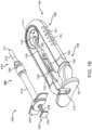
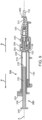
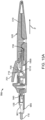
- FIG. 1A shows an implementation of a system for holding, filling, and/or delivering an ocular implant.
- the system 100 can include an ocular implant handling system including an implant carrier member 105 and a handle member 115.
- the system 100 can further include a fill syringe 205 (see FIG. 1B ).
- the fill syringe 205 can contain a therapeutic agent, such as a pre-filled syringe.
- the carrier member 105 is sized and shaped to initially store an implant 110 prior to implantation of the implant 110 into the eye.
- the fill syringe 205 can interface with the carrier member 105 to fill the implant 110 with a flowable material, such as a liquid drug or therapeutic agent.
- the fill syringe 205 can interdigitate with the carrier member 105 holding the implant 110 and lock into a portion of the carrier member 105 (e.g. a guide sleeve), as will be described in more detail below.
- the therapeutic agent or agents suitable for use with the implant 110 can vary, for example, as described in U.S. Patent No. 8,623,395 , entitled "Implantable Therapeutic Device," which is incorporated here in its entirety.
- the therapeutic agent can include one or more of a variety of active ingredients of the therapeutic agent, a formulation of the therapeutic agent, a commercially available formulation of the therapeutic agent, a physician prepared formulation of therapeutic agent, a pharmacist prepared formulation of the therapeutic agent, or a commercially available formulation of therapeutic agent having an excipient.
- the therapeutic agent may be referred to with generic name or a trade name.
- a portion of the carrier member 105 can guide and properly align a cannula or needle 210 of the syringe 205 with the fill port of the implant 110.
- the syringe 205 can interdigitate with this portion of the carrier member 105 and lock into it such that when the syringe 205 is removed, for example, after filling the implant 110 with the drug from the syringe 205, the syringe 205 and this portion of the carrier member 105 locked onto the syringe can be withdrawn together.
- the fill syringe 205 is removed (e.g.
- the handle member 115 can be inserted into the carrier member 105 and used to remove the implant 110 from the carrier member 105.
- the handle member 115 and the carrier member 105 can interchangeably couple to the implant 110.
- the handle member 115 can be coupled to the carrier member 105 in a manner that attaches the implant 110 to the handle member 115 and detaches the implant 110 from the carrier member 105.
- the handle member 115 can then be used to position the implant 110 and insert the implant 110 into an eye.
- the implant 110 can be pre-filled and stored within the carrier member 105.
- the implant 110 can be stored within the carrier member 105 while empty and filled prior to implantation in the eye, such as using a pre-filled syringe.
- the implant 110 can be filled after implantation in the eye.
- the implant 110 to be used with the system 100 described herein can include an internal reservoir.
- the reservoir can be a rigid-walled reservoir having a fixed volume.
- one or more of the reservoir walls can be configured to expand such that the reservoir volume changes depending on a fill status of the implant 110.
- the implant 110 can include a proximal retention structure 305 and an indentation 307 or narrowed region that is sized smaller than the retention structure 305.
- the indentation 307 can also be sized smaller than a shoulder region extending distal to the indentation 307.
- the indentation 307 can be sized to fit in an elongate incision.
- the proximal retention structure 305 can include an access port having a penetrable region.
- the proximal retention structure 305 can include or be covered by a penetrable barrier or septum structure such that the reservoir can be filled with a material.
- One or more outlets can be positioned in fluid communication with the reservoir of the implant 110 such that therapeutic agent in the reservoir can be delivered to the patient.
- the one or more outlets can incorporate a porous structure including one or more of many porous structures such as sintered material, openings in a non-permeable material, openings having a size and number to release therapeutic agent at an intended rate, a plurality of holes etched in a material, a semipermeable membrane, or nano-channels, for example.
- the configuration of implant 110 that can used with the system 100 described herein can vary.
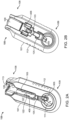
- the carrier member 105 includes a shell 101 and a guide sleeve 120.
- the guide sleeve 120 is removably attached to the shell 101.
- the system 100 also includes an implant holder 125 configured to releaseably hold an ocular implant 110 within the shell 101.
- the implant holder 125 can be reversibly coupled to the shell 101 of the carrier member 105.
- implant holder 125 can be an interchangeable element that can be coupled to the carrier member 105, for example prior to filling with a syringe 205, and can be released from the carrier member 105, for example after filling with a syringe 205 and prior to implantation in a patient using a delivery tool.
- the implant holder 125 can be interchangeably coupled with the carrier member and the delivery tool.
- the shell 101 of the carrier member 105 includes a central channel 103 extending at least partially through an upper surface of a first side, such as its front side 107, from a proximal end 108 of the carrier member 105 towards a distal end region 109 of the carrier member 105 along a longitudinal axis.
- the central channel 103 can terminate at an opening or window 111 extending through a distal end region 109 of the shell 101.
- the implant 110 can be positioned by the implant holder 125 within the window 111.
- the shell 101 of the carrier member 105 can be generally ergonomically shaped such that a user can hold the carrier member 105 in one hand positioned around the underside of the carrier member 105.
- the central channel 103 can be available and readily visible on the front side 107 of the carrier member 105.
- the shell 101 of the carrier member 105 can include one or more textured regions 112 or indentations on its external surface to improve a user's grip on the carrier member 105 during use.
- the implant 110 can have an elongate axis extending through a center of the implant 110 from the proximal-most end to the distal-most end of the implant 110.
- the system 100 (and/or each of the components of the system) can also have an elongate axis that is concentric with the elongate axis of the implant 110 forming a longitudinal axis A with which each of the components of the system 100 are substantially aligned.
- the elongate axis of the implant 110 can be aligned substantially with the longitudinal axis A of the system and the syringe 205 can be inserted substantially along the longitudinal axis A such that the needle 211 penetrates an upper surface of the implant 110.
- the syringe 205 can interdigitate within the central channel 103 along the longitudinal axis A or, in other implementations, can be inserted at an angle to the longitudinal axis A.
- the carrier member 105 can include the guide sleeve 120 that can be removably attached within at least a region of the slot of the shell 101.
- the guide sleeve 120 can define a proximal port 113 into the central channel 103 of the shell 101 that allows for access to the slot from a proximal end of the shell 101.
- the guide sleeve 120 can help to ensure proper alignment between the syringe 205 and the implant 110 such that a needle 211 of the syringe 205 inserts through a septum or fill port of the implant 110.
- the guide sleeve 120 can provide guiding alignment during insertion of the syringe 205 through the port 113 into the central channel 103 towards the implant 110 mounted within the implant holder 125 of the carrier member 105.
- the configuration of the guide sleeve 120 can vary.
- the guide sleeve 120 can have a length such that it extends a distance between the proximal end 108 of the shell 101 or central channel 103 and a distal region of the central channel 103.
- the guide sleeve 120 can be relatively flush with a proximal end 108 of the shell 101 (see FIGs. 2A and 2B ) or the guide sleeve 120 can extend a distance beyond the proximal end 108 of the shell 101, for example, as shown in FIG. 1A-1B .
- the guide sleeve 120 can incorporate a gripping element 121.
- the gripping element 121 of the guide sleeve 120 may have an ergonomic size and shape that facilitates it being grasped by a user, such as between the fingers of a user's hand as will be described in more detail below.
- the guide sleeve 120 can have a generally cylindrical shape.
- the guide sleeve 120 can be a generally cylindrical element having an overall c-shaped cross section such that the underside or back side of the guide sleeve 120 is cylindrical and the front side of the guide sleeve 120 is slotted or discontinuous (see FIGs. 4A-4B and also FIG. 5C ).
- the cylindrical lower surface of the guide sleeve 120 can abut a lower portion 104 of the shell 101 and the discontinuous portion of the guide sleeve 120 can align with the upper surface of the front side 107 of the shell 101.
- the syringe 205 can have a body sized and shaped to be inserted into the central channel 103 of the shell 101 of the carrier member 105 via the port 113 such that a needle 211 of a needle assembly 210 of the syringe 205 can be inserted into the implant 110 mounted via the implant holder 125 on the carrier member 105.
- the syringe 205 can fill the implant 110 with a liquid drug or any other liquid prior to inserting the implant 110 into the eye.
- the syringe 205 can have any of a variety of configurations as known in the art.
- the syringe 205 can include a reservoir 215 that may be pre-filled with a fluid drug or any other fluid.
- the reservoir 215 can include a proximal opening configured to receive a mechanism for expelling the fluid from the reservoir 215 through a distal opening of the reservoir 215.
- the mechanism for expelling the fluid from the reservoir 215 can be a plunger 225 including a piston rod 230 terminating at a piston head 235.
- the piston head 235 can be configured to contact the liquid to be injected from the reservoir 215 and maintain a seal as the plunger 225 is displaced distally within the reservoir 215.
- a stop element can be incorporated that prevents withdrawal of the piston rod 230 or piston head 235 through the proximal opening.
- a proximal end of the syringe 205 can include a flange 245 that can aid in the advancement of the plunger 225 within the reservoir 215 as is known in the art.
- a user can apply a force against an upper surface of the flange 245 (e.g. with the user's thumb) and apply a force against a lower surface of portion 250 (e.g. with a user's finger) therein applying a squeezing pressure to the syringe 205 engaged with the carrier member 105.
- the distal opening of the reservoir 215 can be in fluid communication with a needle assembly 210 coupled to the syringe by a luer 255 (see FIG. 1B and FIG. 9 ).
- the needle assembly 210 can include a needle 211 and optionally a needle limiter 212 positioned around the needle 211.
- the needle limiter 212 can have a length such that a distal-most tip of the needle 211 extends only a short distance beyond the needle limiter 212 to prevent penetration of the needle 211 within the implant 110 beyond that short distance so as not to damage the implant 110 during filling.
- the needle limiter 212 can abut an internal region of the implant holder 125 or an upper surface of the implant 110 preventing the needle 211 from penetrating the implant 110 beyond a desired depth.
- the syringe 205 can include a needle cap configured to cover the needle 211 and needle limiter 212.
- the needle assembly 210 may be integrally formed with the syringe 205 or the needle assembly 210 may be detachable from the syringe 205.
- the guide sleeve 120 can be removably attached from within the central channel 103 of the shell 101.
- the shell 101 and/or the guide sleeve 120 can include a locking mechanism that reversibly secures the guide sleeve 120 to the shell 101.
- the locking mechanism can be released, for example, upon insertion of the syringe 205 as will be described in more detail below. After the syringe 205 has been inserted into the guide sleeve 120 positioned within the central channel 103 of the shell 101 such as to inject drug into the implant 110, the locking mechanism between the guide sleeve 120 and the shell 101 can unlock.
- the guide sleeve 120 can release from the shell 101 and lock onto the syringe 205 such that both the guide sleeve 120 and the syringe 205 can be removed from the shell 101 upon withdrawal of the syringe 205 from the implant 110.
- the locking mechanism can simultaneously release the guide sleeve 120 from the shell 101 and lock the guide sleeve 120 onto a region of the syringe 205.
- the locking mechanism holding the guide sleeve 120 onto the syringe 205 can be activated or locked and the locking mechanism locking the guide sleeve 120 to the shell 101 can be deactivated or unlocked.
- the respective locking mechanisms can activate/deactivate in a simultaneous or step-wise manner.
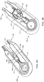
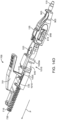
- FIG. 6 shows an implementation of the system 100 with the syringe 205 inserted into the carrier 105.
- FIG. 7 shows an implementation of the system 100 after the syringe 205 has been used to fill the implant 110 and the syringe 205 has been decoupled from the carrier member 105.
- the guide sleeve 120 is shown detached from the carrier member 105 and is now attached to the syringe 205. It should be appreciated that unlocking or detaching the guide sleeve 120 from the carrier member 105 is not dependent upon filling the implant 110.
- the locking mechanism between the shell 101 and the guide sleeve 120 can include one or more corresponding slots and tabs providing a fixed, but reversible coupling between the shell 101 and the guide sleeve 120.
- the guide sleeve 120 can include one or more slots 122 having a size and shape configured to accept tabs 405 of the shell 101 such that the tabs 405 reversibly insert through the slots 122 when the guide sleeve 120 is positioned within the central channel 103 of the shell 101.
- the slots 122 can be located on opposing sides of the guide sleeve 120.
- the guide sleeve 120 can also include one or more tabs 123 formed by a u-shaped slot 126 through a thickness of the guide sleeve 120. It should be appreciated that tabs 405 as well as tabs 123 can have a degree of flexibility such that they can move slightly with respect to the longitudinal axis A of the system to provide for reversible attachment between the guide sleeve 120 and the shell 101 as well as between the guide sleeve 120 and the syringe 205, which will be described in more detail below.
- FIGs. 3A-3B , 4A-4B and also FIGs. 8A-8B show an implementation of a locking mechanism that initially locks the guide sleeve 120 to the shell 101 of the carrier member 105.
- the shell 101 can include one or more tabs 405 configured to insert through one or more corresponding slots 122 in the guide sleeve 120.
- the tabs 405 are shown in a first state that locks the guide sleeve 120 to the shell 101 of the carrier member 105.
- the flexible tabs 405 can extend through the corresponding slots 122 in the guide sleeve 120 preventing withdrawal of the guide sleeve 120 in a proximal direction along arrow P.
- FIG. 8B shows a syringe 205 inserted distally into the guide sleeve 120 such that an outer surface of the needle assembly 210 of the syringe 205 presses against an inner surface of the flexible tabs 405 urging them in outward direction.
- the proximal end of the tabs 405 can be ramped such that the outer surface of the needle assembly 210 can smoothly press against and slide along the inner surface of the tabs 405 as the syringe 205 is urged in a distal direction along arrow D.
- the tabs 405 can be urged back out the slots 122 in the guide sleeve 120 releasing the locking engagement between the slots 122 of the guide sleeve 120 and the tabs 405 of the shell 101.
- the edge 124 of the slot 122 may no longer abut the distal edge 408 of the tab 405.
- This same act of inserting the syringe 205 distally through the guide sleeve 120 releasing the locked engagement between the guide sleeve 120 and the shell 101 can also cause the guide sleeve 120 to lock onto a portion of the syringe 205.
- the one or more tabs 123 formed by the u-shaped slot 126 through a thickness of the guide sleeve 120 for example, in the cylindrical underside of the guide sleeve 120 (see FIG. 4B and also FIG. 9 ).
- the tab 123 on the guide sleeve 120 can flex inward and outward relative to a longitudinal axis A of the guide sleeve 120 to capture a corresponding portion of the syringe 205.
- a free end 128 of the tab 123 can be angled or curved such that it projects inward towards the longitudinal axis of the guide sleeve 120, or have a feature that encroaches within the interior of the sleeve 120.
- the flexible tab 123 of the guide sleeve 120 can capture the corresponding portion of the syringe 205 preventing the syringe 205 from being detached from the carrier member 105 without the guide sleeve 120 being coupled to the syringe 205.
- the guide sleeve 120 can include an inner diameter configured to receive the outer diameter of the syringe 205 such that the syringe 205 can be inserted through the guide sleeve 120 to inject drug into the implant 110 mounted within the implant holder 125 located distal to the guide sleeve 120 (see FIG. 9 ).
- the free end 128 of the flexible tab 123 of the guide sleeve 120 projecting inward towards the central longitudinal axis A of the system 100.
- the syringe 205 can urge the flexible tab 123 outward away from the central longitudinal axis A as the syringe 205 is inserted through the guide sleeve 120.
- a distal region of the syringe 205 can include a first portion 206 having a first outer diameter and a second portion 208 having a second outer diameter. The first portion 206 can be located distally to the second portion 208 and the first outer diameter can be larger than the second outer diameter.
- the outer diameter of the first portion 206 can abut the free end 128 of the tab 123 urging the tab 123 outward. Once the first portion 206 is advanced distal to the tab 123, the free end 128 can flex back inward towards the longitudinal axis A and towards the smaller diameter second portion 208 located proximal to the first portion 206.
- the first portion 206 can have a proximal ledge 209 such that if the syringe 205 is withdrawn in a proximal direction, the free end 128 of the tab 123 can abut the proximal ledge 209 and cause the now-released guide sleeve 120 to withdraw along with the syringe 205.
- an implant holder 125 is removably attached within at least a region of the central channel 103 of the shell 101.
- the implant holder 125 can be positioned such that an interior 901 of the implant holder 125 is coaxial with the central channel 103 of the carrier member 105 and the guide sleeve 120 (see FIG. 2A ).
- a proximal end 902 of the implant holder 125 can lie adjacent to the distal end of the guide sleeve 120 and a distal end 903 of the implant holder 125 can extend beyond the central channel 103 into the window 111.
- the interior 901 of the implant holder 125 can be configured to receive at least a portion of the needle assembly 210 of the syringe 205 (see FIG. 6 ), as will be described in more detail below.
- the implant holder 125 includes a pair of moveable mating graspers 905a, 905b configured to releasably secure the implant 110 to the carrier member 105.
- the implant 110 can include a proximal retention structure 305 that can include an indentation 307 dimensioned to receive first protrusion 907a of a first grasper 905a and a second protrusion 907b of a second grasper 905b to hold the implant 110 therebetween.
- the protrusions 907a, 907b can be shaped in a variety of ways to engage the implant 110, including lentoid, oval, elliptical, or circular structures.
- the protrusions 907a, 907b can include a structure similar to the shape profile or outer contour or corresponding geometry of the indentation of the implant 110.
- first protrusion 907a on the first grasper 905a can include a proximal surface 910a to engage a region of the distal surface 306a of the retention structure 305
- second protrusion 907b on the second grasper 905b can include a proximal surface 910b to engage another region of the distal surface 306b of the retention structure 305.
- the first grasper 905a can be urged toward the second grasper 905b to slide the first protrusion 907a and the second protrusion 907b into the indentation 307 of the retention structure 305 such that the proximal surfaces 910a, 910b engage the distal surfaces 306a, 306b.
- the graspers 905a, 905b can extend substantially around a portion of the retention structure 305 of the implant 110 to hold the implant 110.
- the septum or fill port of the implant 110 can be available within the interior 901 of the implant holder 125 and the body of the implant 110 can extend beyond the implant holder 125.
- the implant 110 can be held by the implant holder 125 such that a longitudinal axis of the implant 110 is aligned substantially concentric or coaxial with the longitudinal axis A of the system 100.
- the syringe needle 211 can be inserted coaxially along the axis A of the implant 110 such that the needle 211 of the syringe 205 is advanced along the axis A toward the proximal end of the implant 110.
- the needle 211 of the syringe 205 can penetrate the fill port until a needle stop 212 contacts the proximal surface 910 of the graspers 905 or a proximal end of the implant 110 preventing further penetration of the needle 211.
- the interior 901 of the implant holder 125 as well as the guide sleeve 120 can further aid in aligning the syringe 205 and the needle 211 with the implant 110 and with the longitudinal axis A.
- the implant holder 125 can additionally incorporate an opening into the interior 901 such that a needle can be inserted at an angle to the longitudinal axis A.
- the implant holder 125 can be an interchangeable element that can lock in an alternating fashion with different portions of the system 100, such as the shell 101 of the carrier 105 and a portion of the handle member 115.
- the proximal end 902 of the implant holder 125 can be reversibly coupled to a region of the shell 101 such as within the central channel 103 by a locking mechanism.
- the locking mechanism can be configured to unlock the implant holder 125 from the shell 101 and then lock the implant holder 125 onto the handle member 115 once the handle member 115 is inserted into the carrier member 105, which is described in more detail below.
- the implant holder 125 can be attached to the region of the shell 101 and then attached to the handle member 115 upon release from the shell 101.
- the locking mechanism can include an indentation 912 near a proximal end 902 of the implant holder 125 configured to receive a correspondingly shaped element 410 of the shell 101 (see FIG. 3A and also FIG. 13 ).
- the indentation 912 can have smooth edges such that the implant holder 125 can be removed from the element 410, as will be described in more detail below.
- the locking mechanism can also include a tab 914 formed by a u-shaped slot 916 located adjacent the indentation 912, such as just distal to the indentation 912.
- the tab 914 can include a projection 918 on its inner surface (see FIG. 10F ) configured to engage with a correspondingly shaped recess 505 within a region of the handle member 115 when the handle member 115 is inserted through the interior 901 of the implant holder 125 as will be described in more detail below.
- the system 100 can also include the handle member 115.
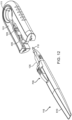
- the handle member 115 can be attached to the implant holder 125 holding the implant 110 (see FIG. 11 and 12 ).
- the implant holder 125 can be interchangeably attached to the shell 101 of the carrier 105 and the handle member 115.
- Insertion of the handle member 115 into the carrier member 105 can release the attachment of the implant holder 125 with the shell 101 and cause the attachment between the implant holder 125 and the handle member 115 such that the implant holder 125 can be removed from the carrier 105 and the handle member 115 can be used to insert the implant being held by the implant holder 125 into a patient.
- the handle member 115 can include an elongated proximal portion 510 that can be grasped by a user and the distal attachment portion 130 that can releaseably attached to the implant 110 via the implant holder 125.
- the proximal portion 510 of the handle member 115 can be sized and shaped to be grasped by a user and can have an ergonomic shape that facilitates quick and easy positioning of the implant 110 and release of the implant 110 into the patient.
- the distal attachment portion 130 of the handle member 115 can be inserted into the central channel 103 of the carrier member 105 after removal of the guide sleeve 120 from the central channel 103.
- the attachment portion 130 can removably attach, engage or otherwise mate with the implant holder 125 of the carrier member 105, which holds the implant 110 (see FIG. 11 ).
- the handle member 115 can be removed from the carrier member 105 such that it takes the implant holder 125 (and attached implant 110) out of the carrier member 105 along with it.
- the handle member 115 can then be used to manipulate the implant 110 held by the implant holder 125 such that the implant 110 can be inserted into an eye.
- FIG. 12 shows handle member 115 after it has been removed from the carrier member 105 with the removable implant holder 125 now attached to the handle member 115.
- the proximal end 902 of the implant holder 125 can be reversibly coupled to a region of the shell 101 by a locking mechanism configured to unlock the implant holder 125 from the shell 101 and lock the implant holder 125 onto the handle member 115 once the handle member 115 is inserted into the carrier member 105.
- the locking mechanism can include the indentation 912 located near a proximal end 910 of each grasper 905 and the tab 914 adjacent the indentation 912 having the projection 918 on its inner surface.
- the projection 918 can have a ramped proximal end and a flat lower surface 920.
- the correspondingly-shaped element 410 of the shell 101 can rest within the indentation 912.
- the attachment portion 130 of the handle 115 is inserted through the implant holder 125, the projection 918 on the inner surface of the tab 914 can insert within the recess 505 near the distal end of the attachment portion 130.
- Distal movement of the attachment portion 130 along arrow D through the interior 901 of the implant holder 125 can cause the tab 914 to flex slightly outward as the outer surface of the distal end of the attachment portion 130 slides past the ramped surface of the projection 918 on the inner surface of the tab 914.
- the tab 914 can flex back inward such that the projection 918 snaps into the recess 505.
- the recess 505 and the projection 918 can have corresponding shapes such that the projection 918 can be received at least in part within the recess 505. Further distal movement of the handle 115 through the interior 901 of the implant holder 125 can be prevented due to contact between the distal-most end of the attachment portion 130 and a surface 925 of the interior 901 of the implant holder 125. Thus, a region of the attachment portion 130 between the recess 505 and the distal-most end of the attachment portion 130 can be captured between the projection 918 and this surface 925 (see FIG. 13 ).
- Proximal withdrawal of the handle 115 along arrow P from the central channel 103 of the shell 101 can cause a lower surface 920 of the projection 918 to abut a distal wall 515 of the recess 505 causing the implant holder 125 to be withdrawn with the handle 115 in a proximal direction along arrow P out from the central channel 103.
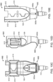
- the handle member 115 can have at least one deployment mechanism including an actuator 705, such as a button, knob, slider, etc., that can be actuated to detach the implant 110 from the implant holder 125 and handle member 115.
- the actuation of the actuator 705 can simply release the implant 110 or it can push or otherwise expel the implant 110 from the handle member 115.
- FIGS. 14A and 14B shows an implementation of a deployment mechanism that releases the implant 110 from the handle member 115 upon actuation of the actuator 705.
- the implant holder 125 can include a pair of movable tips or graspers 905 that grasp the implant 110 such that when the handle member 115 is inserted within the interior 901 of the implant holder 125 the graspers 905 secure the implant 110 to the handle member 115.
- the graspers 905 can be positioned such that they hold the implant 110 in a secured position relative to the handle member 115.
- the actuator 705 is depressed, the graspers 905 can separate and release the implant 110 as shown in FIG. 14B .
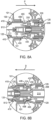
- FIG. 15A-15B show cross-sectional views of an implementation of the deployment mechanism.
- the actuator 705 can be pressed (or slide) so as to exert a force onto a spring held slider member 1005.
- the force of the actuator 705 can slide the slide member 1005 to a position that causes the graspers 905 to open.
- the amount of force required to slide the slider member 1005 forward and open the graspers 905 can be variable.
- the slider member 1005 and the actuator interface at ramped connection can have different ramp angles resulting in a smoothing of the force required for the user to open the handle tips.
- the actuator 705 can include an actuator element 701 configured to pivot around a pivot pin 710 when the actuator 705 is depressed towards an upper surface 520 of the handle member 115.
- the actuator element 701 can also include a projection 715 extending from its lower surface 720 such that as the element 701 pivots around the pivot pin 710 the projection 715 is moved downwards such that the ramped surface 725 of the projection 715 slides along a ramped surface 1010 of the slider member 1005. This contact between the ramped surface 725 of the projection 715 against the ramped surface 1010 of the slider member 1005 can cause the slider member 1005 to move in a proximal direction against the force of the spring 730 compressing the spring 730.
- the slider member 1005 can have a forked region 1015 near its distal end.
- the attachment portion 130 of the handle member 115 can interface with the forked region 1015.
- the attachment portion 130 can include a first arm 525 rotatably coupled to a second arm 530 around a pivot point 535.
- the first arm 525 and second arm 530 can be biased such as by a spring or other element such that their distal ends 540 are urged towards one another.
- the distal region 540 of the arms 525, 530 can extend within the interior 901 of the implant holder 125 such that the projections 918 of the implant holder 125 mate with the recesses 505 on the arms 525, 530.
- a region 545 of the arms 525, 530 proximal of the pivot point 535 can interface with the forked region 1015 of the slider member 1005.
- a first prong 1020a of the forked region 1015 can rest against a first region 550 of the arm 525 and a second prong 1020b of the forked region 1015 can rest against a second region 550 of the arm 530 (see FIG. 14A ).
- the first and second prongs 1020a, 1020b can slide relative to the arms 525, 530 such that they abut a ramped proximal end 545 of each respective arm 525, 530 and cause the arms 525, 530 to open or pivot relative to one another around pivot point 535.
- the distal region 540 of the arms 525, 530 can move away from one another in a scissor-like movement.
- the actuator element 701 can be arranged relative to the arms 525, 530 of the handle member 115 such that as the actuator element 701 is pressed downwards towards the upper surface of the handle member 115, the arms 525, 530 can each move outward at an angle away from the longitudinal axis A of the system 100 and from one another.
- the arms 525, 530 can be configured to move away from one another such that one arm moves to a first side and the opposing arm moves to a second opposite side away from the longitudinal axis A of the system 100.
- the arms 525, 530 also can be configured to move away from one another such that one arm moves upwards and one arm moves downwards away from the longitudinal axis A of the system 100.
- the actuator element 701 can be positioned on an upper surface of the handle member 115 from the point of view of the user such that the actuator element 701 is pressed using a thumb and the actuator element 701 moved towards the upper surface of the handle member 115.
- the actuator element 701 also can be positioned on a lower surface of the handle member 115 from the point of view of the user such that the actuator element 701 is pressed using a finger and the actuator element 701 moved towards the lower surface of the handle member 115.
- the kit can include sterile packaging within which one or more components of the system 100 can be contained including the carrier member 105 having a guide sleeve 120 and implant holder 125 attached.
- An implant 110 can be held within the implant holder 125 or the implant 110 can be contained within sterile packaging separated from the system 100 such that the implant 110 is engaged with the implant holder 125 after the sterile kit has been opened.
- the kit can further include a handle member 115.
- the kit can further include needle assembly 210 configured to couple to a pre-filled syringe. Alternatively, the kit can include the syringe.
- the kit can further include a removal tool.
- the kit can include a carrier member 105 having a guide sleeve 120 and having an implant holder 125 coupled to the shell 101 of the carrier member 105.
- the implant holder 125 can be reversibly coupled to an implant 110.
- the implant 110 can be empty.
- the kit can further include a handle member 115 configured to engage with the implant holder 125 holding the implant 110 after the implant 110 has been filed with a drug.
- a syringe 205 can be provided that is configured to interdigitate with a portion of a carrier member 105 such that a needle of the syringe 205 can insert through a proximal portion of the implant 110 being held by the carrier member 105 to fill the implant 110 with a drug.
- the syringe 205 can be pre-filled with one or more therapeutic agents.
- the carrier member 105 can include a guide sleeve 120 configured to lock onto a portion of the syringe 205 upon insertion of the syringe 205 into the guide sleeve 120 of the carrier member 105.
- the implant 110 can be held by an implant holder 125 locked onto the carrier member 105, such as within the central channel 103.
- the implant holder 125 holding the implant 110 can attach to a portion of a handle member 115 after removal of the syringe 205 from the carrier member 105 upon filling of the implant 110.
- the handle member 115 having the implant holder 125 now attached to it can be used to deliver the implant 110 held within the implant holder 125 into a target location of the patient.
- the kit can include a carrier member 105 having a shell 101 and a guide sleeve 120, and an implant holder 125 holding an implant 110.
- the carrier member 105 can have a central channel 103 that facilitates access to the implant 110 being held by the implant holder 125, such as for filling with a syringe 205.
- the syringe 205 can be part of the kit or a separate component.
- the syringe 205 can be pre-filled with one or more therapeutic agents or can be empty.
- the handle member 115 can also be part of the kit or a separate component.
- the implant 110 can be part of the kit or a separate component. In an interrelated aspect, all of the components can be provided as a single kit or can be provided as separate components.
- phrases such as "at least one of” or “one or more of' may occur followed by a conjunctive list of elements or features.
- the term “and/or” may also occur in a list of two or more elements or features. Unless otherwise implicitly or explicitly contradicted by the context in which it is used, such a phrase is intended to mean any of the listed elements or features individually or any of the recited elements or features in combination with any of the other recited elements or features.
- the phrases “at least one of A and B;” “one or more of A and B;” and “A and/or B” are each intended to mean "A alone, B alone, or A and B together.”
- a similar interpretation is also intended for lists including three or more items.
- phrases "at least one of A, B, and C;” “one or more of A, B, and C;” and “A, B, and/or C” are each intended to mean "A alone, B alone, C alone, A and B together, A and C together, B and C together, or A and B and C together.”
Landscapes
- Health & Medical Sciences (AREA)
- Ophthalmology & Optometry (AREA)
- Veterinary Medicine (AREA)
- Life Sciences & Earth Sciences (AREA)
- Animal Behavior & Ethology (AREA)
- General Health & Medical Sciences (AREA)
- Public Health (AREA)
- Engineering & Computer Science (AREA)
- Biomedical Technology (AREA)
- Heart & Thoracic Surgery (AREA)
- Vascular Medicine (AREA)
- Chemical & Material Sciences (AREA)
- Medicinal Chemistry (AREA)
- Pharmacology & Pharmacy (AREA)
- Epidemiology (AREA)
- Nuclear Medicine, Radiotherapy & Molecular Imaging (AREA)
- Surgery (AREA)
- Anesthesiology (AREA)
- Hematology (AREA)
- Infusion, Injection, And Reservoir Apparatuses (AREA)
- Prostheses (AREA)
Claims (12)
- Okularimplantat-Handhabungs- und Füllsystem (100), das Folgendes umfasst:ein Trägerelement (105), das Folgendes umfasst:eine Schale (101) mit einem zentralen Kanal (103), der sich zumindest teilweise durch die Schale von einem proximalen Ende (108) zu einem distalen Ende (109) der Schale erstreckt;eine Führungshülse (120), die entfernbar in mindestens einem ersten Bereich des zentralen Kanals der Schale angebracht ist, wobei die Führungshülse eine proximale Öffnung (113) in den zentralen Kanal definiert, die vom proximalen Ende der Schale zugänglich ist; undeinen Implantathalter (125), der entfernbar in mindestens einem zweiten Bereich des zentralen Kanals der Schale angrenzend an ein distales Ende der Führungshülse angebracht ist, wobei der Implantathalter ein Paar Greifer (905a, 905b) aufweist, die dafür ausgelegt sind, ein Okularimplantat (110) an einem distalen Ende (903) des Implantathalters lösbar zu befestigen; undeine Füllspritze (205), die so bemessen und geformt ist, dass sie durch die Öffnung (113) in den zentralen Kanal (103) durch die Führungshülse (120) eingeführt werden kann.
- System nach Anspruch 1, das ferner das Okularimplantat (110) umfasst, wobei das Okularimplantat eine Rückhaltestruktur und ein Reservoir umfasst, das so bemessen und geformt ist, dass es mindestens teilweise in ein Auge eingeführt werden kann, so dass ein Arzneimittel durch das Implantat aus dem Reservoir in das Auge abgegeben werden kann.
- System nach Anspruch 1 oder Anspruch 2, das ferner ein Griffelement (115) umfasst, das zum Einführen eines Okularimplantats (110) in ein Auge verwendet werden kann und einen länglichen proximalen Abschnitt und einen distalen Befestigungsabschnitt umfasst.
- System nach Anspruch 3, wobei der Implantathalter (125) dafür konfiguriert ist, austauschbar mit dem Trägerelement (105) und dem Griffelement (115) zu koppeln.
- System nach einem der vorhergehenden Ansprüche, wobei sich die Führungshülse (120) gleichzeitig von der Schale (101) löst und an der Füllspritze befestigt wird, wenn die Füllspritze in den zentralen Kanal (103) eingeführt wird.
- System nach einem der vorhergehenden Ansprüche, wobei die Führungshülse (120) mindestens einen Führungshülsenschlitz aufweist, der so bemessen und geformt ist, dass er eine entsprechende Lasche des Gehäuses aufnimmt, die in den mindestens einen Führungshülsenschlitz hineinragt, wenn die Führungshülse in dem zentralen Kanal positioniert ist.
- System nach einem der vorhergehenden Ansprüche, wobei die Füllspritze (205) so bemessen und geformt ist, dass sie durch einen Bereich des Trägerelements (105), das ein Okularimplantat (110) hält, eingeführt werden kann, wobei die Füllspritze (205) dafür konfiguriert ist, ein oder mehrere therapeutische Mittel aus der Füllspritze (205) in ein Reservoir des Okularimplantats (110) zu injizieren, und wobei die Füllspritze (205) einen Verriegelungsabschnitt aufweist, der so ausgelegt ist, dass er mit einem Teil der Führungshülse (120) verriegelt, wenn die Füllspritze (205) durch den zentralen Kanal der Schale (101) eingeführt wird.
- System nach Anspruch 7, wobei der Verriegelungsabschnitt so konfiguriert ist, dass beim Herausziehen der Füllspritze aus dem Trägerelement die Führungshülse (120) aus dem Gehäuse entfernt wird.
- System nach Anspruch 7 oder 8, wobei die Füllspritze (205) einen ersten Abschnitt (206) mit einem ersten Außendurchmesser und einen zweiten Abschnitt (208) mit einem zweiten Außendurchmesser aufweist, der kleiner ist als der erste Außendurchmesser.
- System nach einem der Ansprüche 7 bis 9, wobei der Verriegelungsabschnitt eine Leiste (209) zum Eingriff in eine Lasche (123) der Führungshülse (120) umfasst.
- System nach einem der Ansprüche 7 bis 10, wobei die Füllspritze (205) mit dem einen oder den mehreren therapeutischen Wirkstoffen vorgefüllt ist.
- System nach einem der Ansprüche 7-11, wobei die Füllspritze (205) einen Flansch (245) umfasst, der dafür konfiguriert ist, das Vorschieben eines Kolbens (25) der Füllspritze zu unterstützen.
Applications Claiming Priority (3)
| Application Number | Priority Date | Filing Date | Title |
|---|---|---|---|
| US201462024682P | 2014-07-15 | 2014-07-15 | |
| PCT/US2015/040633 WO2016011191A1 (en) | 2014-07-15 | 2015-07-15 | Ocular implant delivery device and method |
| EP15821698.6A EP3169289B1 (de) | 2014-07-15 | 2015-07-15 | Augenimplantateinführungssystem |
Related Parent Applications (2)
| Application Number | Title | Priority Date | Filing Date |
|---|---|---|---|
| EP15821698.6A Division EP3169289B1 (de) | 2014-07-15 | 2015-07-15 | Augenimplantateinführungssystem |
| EP15821698.6A Division-Into EP3169289B1 (de) | 2014-07-15 | 2015-07-15 | Augenimplantateinführungssystem |
Publications (3)
| Publication Number | Publication Date |
|---|---|
| EP3679908A1 EP3679908A1 (de) | 2020-07-15 |
| EP3679908B1 true EP3679908B1 (de) | 2024-09-04 |
| EP3679908C0 EP3679908C0 (de) | 2024-09-04 |
Family
ID=55079028
Family Applications (2)
| Application Number | Title | Priority Date | Filing Date |
|---|---|---|---|
| EP20161007.8A Active EP3679908B1 (de) | 2014-07-15 | 2015-07-15 | Vorrichtung zur einführung von augenimplantaten |
| EP15821698.6A Active EP3169289B1 (de) | 2014-07-15 | 2015-07-15 | Augenimplantateinführungssystem |
Family Applications After (1)
| Application Number | Title | Priority Date | Filing Date |
|---|---|---|---|
| EP15821698.6A Active EP3169289B1 (de) | 2014-07-15 | 2015-07-15 | Augenimplantateinführungssystem |
Country Status (15)
| Country | Link |
|---|---|
| US (4) | US10258503B2 (de) |
| EP (2) | EP3679908B1 (de) |
| JP (1) | JP6581194B2 (de) |
| KR (1) | KR102416726B1 (de) |
| CN (1) | CN106687079B (de) |
| AU (1) | AU2015289625B2 (de) |
| BR (1) | BR112017000774B1 (de) |
| CA (1) | CA2955186C (de) |
| ES (2) | ES2803102T3 (de) |
| IL (1) | IL250079B (de) |
| MX (1) | MX384889B (de) |
| MY (1) | MY182497A (de) |
| RU (1) | RU2695563C2 (de) |
| WO (1) | WO2016011191A1 (de) |
| ZA (1) | ZA201700387B (de) |
Families Citing this family (24)
| Publication number | Priority date | Publication date | Assignee | Title |
|---|---|---|---|---|
| AU2010208046B2 (en) | 2009-01-29 | 2014-10-02 | Forsight Vision4, Inc. | Posterior segment drug delivery |
| WO2013116061A1 (en) | 2012-02-03 | 2013-08-08 | Forsight Vision4, Inc. | Insertion and removal methods and apparatus for therapeutic devices |
| CN105246438B (zh) | 2013-03-28 | 2018-01-26 | 弗赛特影像4股份有限公司 | 用于输送治疗物质的眼科植入物 |
| ES2803102T3 (es) | 2014-07-15 | 2021-01-22 | Forsight Vision4 Inc | Dispositivo de administración de implante ocular |
| WO2016014996A1 (en) | 2014-07-24 | 2016-01-28 | Sinopsys Surgical, Inc. | Apparatuses, tools, kits and methods relating to paranasal sinus access |
| RU2017105844A (ru) | 2014-08-08 | 2018-09-11 | Форсайт Вижн4, Инк. | Стабильные и растворимые составы ингибиторов рецепторных тирозинкиназ и способы их получения |
| CN110478119B (zh) * | 2014-11-10 | 2022-04-15 | 弗赛特影像4股份有限公司 | 可膨胀药物递送装置和使用方法 |
| WO2017087902A1 (en) | 2015-11-20 | 2017-05-26 | Forsight Vision4, Inc. | Porous structures for extended release drug delivery devices |
| CN113017981B (zh) | 2016-04-05 | 2023-07-25 | 弗赛特影像4股份有限公司 | 药物递送装置 |
| JP7408542B2 (ja) * | 2017-09-20 | 2024-01-05 | シノプシス サージカル インコーポレイテッド | 副鼻腔流体アクセス埋め込み器具、アセンブリ、キット、および方法 |
| CN111655206B (zh) | 2017-11-21 | 2022-10-14 | 弗赛特影像4股份有限公司 | 用于可扩展端口递送系统的流体交换装置及使用方法 |
| EP3698758A1 (de) * | 2019-02-20 | 2020-08-26 | Leibniz-Institut für Polymerforschung Dresden e.V. | Vorrichtung und anordnungen für ausgerichteten transport, mikroskopische untersuchung und ausgerichtetes ausstossen eines gewebetransplantats oder -implantats |
| CN110507476B (zh) * | 2019-09-12 | 2021-10-26 | 格劳科斯公司 | 制造眼部植入物输送装置的方法 |
| CA3173311A1 (en) * | 2020-02-27 | 2021-09-02 | Istar Medical Sa | Package for retaining and dispensing a delivery shaft assembly for delivery of an implant |
| US20220054311A1 (en) * | 2020-08-12 | 2022-02-24 | United States Government As Represented By The Department Of Veterans Affairs | Eye Drop Dispensing Apparatus |
| US12268633B2 (en) | 2020-11-04 | 2025-04-08 | Alcon Inc. | Medical implant |
| WO2022251710A2 (en) | 2021-05-28 | 2022-12-01 | Sight Sciences, Inc. | Intraocular devices, systems, and methods |
| EP4404748A4 (de) | 2021-09-20 | 2025-06-11 | Mott Corporation | Polymerbeschichtung für medizinische vorrichtungen und herstellungsverfahren |
| USD1037439S1 (en) | 2022-01-17 | 2024-07-30 | EyePoint Pharamaceuticals, Inc. | Ocular injector |
| USD1033637S1 (en) | 2022-01-24 | 2024-07-02 | Forsight Vision4, Inc. | Fluid exchange device |
| CN114848289B (zh) * | 2022-05-06 | 2025-02-14 | 海思盖德(苏州)生物医学科技有限公司 | 一种眼部植入物输送器 |
| CN114983670B (zh) * | 2022-05-30 | 2025-08-01 | 海思盖德(苏州)生物医学科技有限公司 | 一种眼内植入物输送器 |
| USD1101145S1 (en) | 2022-08-11 | 2025-11-04 | Genentech, Inc. | Ocular incision guide tool |
| CN118512302B (zh) * | 2024-07-23 | 2024-10-01 | 苏州朗目医疗科技有限公司 | 一种眼用缓释药输送系统 |
Family Cites Families (369)
| Publication number | Priority date | Publication date | Assignee | Title |
|---|---|---|---|---|
| US2585815A (en) | 1947-01-16 | 1952-02-12 | Mclintock Duncan Menzies | Injection syringe |
| US2564977A (en) | 1949-01-19 | 1951-08-21 | Hu Quang Hsi | Medical injecting apparatus |
| US3232117A (en) | 1962-09-14 | 1966-02-01 | Roger Gilmont Instr Inc | Micrometer buret |
| US3416530A (en) | 1966-03-02 | 1968-12-17 | Richard A. Ness | Eyeball medication dispensing tablet |
| US3538916A (en) * | 1968-12-19 | 1970-11-10 | Joseph S Wiles | Injection pistol |
| US3618604A (en) | 1969-06-09 | 1971-11-09 | Alza Corp | Ocular insert |
| US3641237A (en) | 1970-09-30 | 1972-02-08 | Nat Patent Dev Corp | Zero order release constant elution rate drug dosage |
| US4034756A (en) | 1971-01-13 | 1977-07-12 | Alza Corporation | Osmotically driven fluid dispenser |
| US3995635A (en) | 1971-09-09 | 1976-12-07 | Alza Corporation | Ocular insert |
| US3828777A (en) | 1971-11-08 | 1974-08-13 | Alza Corp | Microporous ocular device |
| US3916899A (en) | 1973-04-25 | 1975-11-04 | Alza Corp | Osmotic dispensing device with maximum and minimum sizes for the passageway |
| US3902495A (en) | 1974-01-28 | 1975-09-02 | Cavitron Corp | Flow control system |
| US3961628A (en) | 1974-04-10 | 1976-06-08 | Alza Corporation | Ocular drug dispensing system |
| US3949748A (en) | 1974-09-26 | 1976-04-13 | Oscar Malmin | Injection syringe having aspirating and metering capabilities |
| US3949750A (en) | 1974-10-07 | 1976-04-13 | Freeman Jerre M | Punctum plug and method for treating keratoconjunctivitis sicca (dry eye) and other ophthalmic aliments using same |
| US4135514A (en) | 1974-12-23 | 1979-01-23 | Alza Corporation | Osmotic releasing system for administering ophthalmic drug to eye of animal |
| US4014335A (en) | 1975-04-21 | 1977-03-29 | Alza Corporation | Ocular drug delivery device |
| US4034758A (en) | 1975-09-08 | 1977-07-12 | Alza Corporation | Osmotic therapeutic system for administering medicament |
| US3977404A (en) | 1975-09-08 | 1976-08-31 | Alza Corporation | Osmotic device having microporous reservoir |
| US4014333A (en) | 1975-09-22 | 1977-03-29 | Mcintyre David J | Instrument for aspirating and irrigating during ophthalmic surgery |
| US4077407A (en) | 1975-11-24 | 1978-03-07 | Alza Corporation | Osmotic devices having composite walls |
| US4008719A (en) | 1976-02-02 | 1977-02-22 | Alza Corporation | Osmotic system having laminar arrangement for programming delivery of active agent |
| US4014334A (en) | 1976-02-02 | 1977-03-29 | Alza Corporation | Laminated osmotic system for dispensing beneficial agent |
| US4111201A (en) | 1976-11-22 | 1978-09-05 | Alza Corporation | Osmotic system for delivering selected beneficial agents having varying degrees of solubility |
| US4111203A (en) | 1976-11-22 | 1978-09-05 | Alza Corporation | Osmotic system with means for improving delivery kinetics of system |
| US4160452A (en) | 1977-04-07 | 1979-07-10 | Alza Corporation | Osmotic system having laminated wall comprising semipermeable lamina and microporous lamina |
| US4256108A (en) | 1977-04-07 | 1981-03-17 | Alza Corporation | Microporous-semipermeable laminated osmotic system |
| US4220153A (en) | 1978-05-08 | 1980-09-02 | Pfizer Inc. | Controlled release delivery system |
| US4220152A (en) | 1978-05-08 | 1980-09-02 | Pfizer Inc. | Delivery system |
| US4200098A (en) | 1978-10-23 | 1980-04-29 | Alza Corporation | Osmotic system with distribution zone for dispensing beneficial agent |
| US4298000A (en) | 1978-11-08 | 1981-11-03 | Minnesota Mining And Manufacturing Company | Fluid dispensing device |
| US4300557A (en) | 1980-01-07 | 1981-11-17 | The United States Of America As Represented By The Secretary Of The Department Of Health And Human Services | Method for treating intraocular malignancies |
| US4309776A (en) | 1980-05-13 | 1982-01-12 | Ramon Berguer | Intravascular implantation device and method of using the same |
| US4326525A (en) | 1980-10-14 | 1982-04-27 | Alza Corporation | Osmotic device that improves delivery properties of agent in situ |
| US4327725A (en) | 1980-11-25 | 1982-05-04 | Alza Corporation | Osmotic device with hydrogel driving member |
| US4484922A (en) | 1981-06-25 | 1984-11-27 | Rosenwald Peter L | Occular device |
| US4439196A (en) | 1982-03-18 | 1984-03-27 | Merck & Co., Inc. | Osmotic drug delivery system |
| US4475916A (en) | 1982-03-18 | 1984-10-09 | Merck & Co., Inc. | Osmotic drug delivery system |
| US4519801A (en) | 1982-07-12 | 1985-05-28 | Alza Corporation | Osmotic device with wall comprising cellulose ether and permeability enhancer |
| US4673405A (en) | 1983-03-04 | 1987-06-16 | Alza Corporation | Osmotic system with instant drug availability |
| US4883459A (en) | 1983-07-29 | 1989-11-28 | Reynaldo Calderon | Retrograde perfusion |
| US4627850A (en) | 1983-11-02 | 1986-12-09 | Alza Corporation | Osmotic capsule |
| US4777049A (en) | 1983-12-01 | 1988-10-11 | Alza Corporation | Constant release system with pulsed release |
| US4712550A (en) | 1985-04-08 | 1987-12-15 | Sinnett Kevin B | Retinal tack |
| US4609374A (en) | 1985-04-22 | 1986-09-02 | Alza Corporation | Osmotic device comprising means for governing initial time of agent release therefrom |
| US4693886A (en) | 1985-04-22 | 1987-09-15 | Alza Corporation | Osmotic device with inert core |
| EP0201611A1 (de) | 1985-05-10 | 1986-11-20 | B. Braun-SSC AG | Zwei-Kanülen-Spritze |
| US4781675A (en) | 1985-11-27 | 1988-11-01 | White Thomas C | Infusion cannula |
| EP0228185B1 (de) | 1985-11-27 | 1990-07-25 | Thomas C. White | Gewebeimplantierbare Flüssigkeitsverteileinrichtung |
| US4959217A (en) | 1986-05-22 | 1990-09-25 | Syntex (U.S.A.) Inc. | Delayed/sustained release of macromolecules |
| US5322691A (en) | 1986-10-02 | 1994-06-21 | Sohrab Darougar | Ocular insert with anchoring protrusions |
| US4863457A (en) | 1986-11-24 | 1989-09-05 | Lee David A | Drug delivery device |
| IL97538A (en) | 1986-12-23 | 1995-03-15 | Liposome Co Inc | Multilamellar liposomes containing nonphosphate guanindino aminoglycosides and their preparation. |
| US4865846A (en) | 1988-06-03 | 1989-09-12 | Kaufman Herbert E | Drug delivery system |
| US5174999A (en) | 1988-12-13 | 1992-12-29 | Alza Corporation | Delivery system comprising fluid ingress and drug egress |
| WO1990007575A1 (en) | 1988-12-30 | 1990-07-12 | Anderson David M | Stabilized microporous materials and hydrogel materials |
| US5098443A (en) | 1989-03-23 | 1992-03-24 | University Of Miami | Method of implanting intraocular and intraorbital implantable devices for the controlled release of pharmacological agents |
| US5164188A (en) | 1989-11-22 | 1992-11-17 | Visionex, Inc. | Biodegradable ocular implants |
| US5324280A (en) | 1990-04-02 | 1994-06-28 | Alza Corporation | Osmotic dosage system for delivering a formulation comprising liquid carrier and drug |
| US5128145A (en) | 1990-06-13 | 1992-07-07 | Alza Corporation | Dosage form for Parkinson's disease, spasticity and muscle spasms |
| US5084021A (en) | 1990-11-02 | 1992-01-28 | Baldwin Brian E | Patient controlled infusion apparatus and method |
| US5378475A (en) | 1991-02-21 | 1995-01-03 | University Of Kentucky Research Foundation | Sustained release drug delivery devices |
| AU650113B2 (en) | 1991-04-05 | 1994-06-09 | Eli Lilly And Company | Sustained release capsule and formulations |
| US5334189A (en) | 1991-06-03 | 1994-08-02 | Wade Stephen E | Device for controlled diffusion of a chemical substance |
| US5282829A (en) | 1991-08-15 | 1994-02-01 | United States Surgical Corporation | Hollow body implants |
| FR2682090B1 (fr) | 1991-10-03 | 1993-12-31 | Holzstoff Holding Sa | Systeme-reservoir pour diffusion prolongee d'un principe actif. |
| US5681572A (en) | 1991-10-18 | 1997-10-28 | Seare, Jr.; William J. | Porous material product and process |
| US5178622A (en) * | 1991-11-01 | 1993-01-12 | Lehner Ii Robert H | Instrument for implanting a soft intraocular lens |
| US5178635A (en) | 1992-05-04 | 1993-01-12 | Allergan, Inc. | Method for determining amount of medication in an implantable device |
| US6096756A (en) | 1992-09-21 | 2000-08-01 | Albert Einstein College Of Medicine Of Yeshiva University | Method of simultaneously enhancing analgesic potency and attenuating dependence liability caused by morphine and other bimodally-acting opioid agonists |
| US5336175A (en) | 1992-10-29 | 1994-08-09 | Mames Robert N | Method for the treatment of retinal detachments |
| US5443505A (en) | 1993-11-15 | 1995-08-22 | Oculex Pharmaceuticals, Inc. | Biocompatible ocular implants |
| CA2140053C (en) | 1994-02-09 | 2000-04-04 | Joel S. Rosenblatt | Collagen-based injectable drug delivery system and its use |
| US5770076A (en) | 1994-03-07 | 1998-06-23 | The Regents Of The University Of California | Micromachined capsules having porous membranes and bulk supports |
| US5985328A (en) | 1994-03-07 | 1999-11-16 | Regents Of The University Of California | Micromachined porous membranes with bulk support |
| US5516522A (en) | 1994-03-14 | 1996-05-14 | Board Of Supervisors Of Louisiana State University | Biodegradable porous device for long-term drug delivery with constant rate release and method of making the same |
| US5466233A (en) | 1994-04-25 | 1995-11-14 | Escalon Ophthalmics, Inc. | Tack for intraocular drug delivery and method for inserting and removing same |
| AUPM897594A0 (en) | 1994-10-25 | 1994-11-17 | Daratech Pty Ltd | Controlled release container |
| EP0788351B1 (de) | 1994-11-10 | 2003-02-05 | The University of Kentucky Research Foundation | Implantierbare wiederauffüllbare vorrichtung mit gesteuerter freisetzung zur verabreichung von arzneistoffen unmittelbar an einen inneren teil des körpers |
| US5725493A (en) | 1994-12-12 | 1998-03-10 | Avery; Robert Logan | Intravitreal medicine delivery |
| US5554132A (en) | 1995-03-30 | 1996-09-10 | Abbott Laboratories | Hand grip for use with syringe |
| EP0957949B1 (de) | 1995-05-14 | 2004-08-04 | Optonol Ltd. | Intraokulares implantat, einführgerät sowie implantierungsverfahren |
| IL113723A (en) | 1995-05-14 | 2002-11-10 | Optonol Ltd | Intraocular implant |
| US5609629A (en) | 1995-06-07 | 1997-03-11 | Med Institute, Inc. | Coated implantable medical device |
| US6685940B2 (en) | 1995-07-27 | 2004-02-03 | Genentech, Inc. | Protein formulation |
| US5773019A (en) | 1995-09-27 | 1998-06-30 | The University Of Kentucky Research Foundation | Implantable controlled release device to deliver drugs directly to an internal portion of the body |
| US6641708B1 (en) | 1996-01-31 | 2003-11-04 | Board Of Regents, The University Of Texas System | Method and apparatus for fractionation using conventional dielectrophoresis and field flow fractionation |
| GB2310149A (en) | 1996-02-15 | 1997-08-20 | Nomix Chipman Ltd | Spray gun |
| US20090005864A1 (en) | 1996-03-18 | 2009-01-01 | Eggleston Harry C | Modular intraocular implant |
| US5951512A (en) | 1996-05-28 | 1999-09-14 | Horizon Medical Products, Inc. | Infusion port with modified drug reservoir |
| US5797898A (en) | 1996-07-02 | 1998-08-25 | Massachusetts Institute Of Technology | Microchip drug delivery devices |
| US5928662A (en) | 1996-07-31 | 1999-07-27 | Phillips; Andrew F. | Ocular drug delivery device |
| AU7533696A (en) | 1996-12-13 | 1998-06-18 | Ciba-Geigy Ag | New materials |
| WO1998043611A1 (en) | 1997-03-31 | 1998-10-08 | Alza Corporation | Diffusional implantable delivery system |
| US7160687B1 (en) | 1997-05-29 | 2007-01-09 | Cellomics, Inc. | Miniaturized cell array methods and apparatus for cell-based screening |
| US5902598A (en) | 1997-08-28 | 1999-05-11 | Control Delivery Systems, Inc. | Sustained release drug delivery devices |
| US6039712A (en) | 1997-11-04 | 2000-03-21 | Terence M. Fogarty | Implantable injection port |
| US8313454B2 (en) * | 1997-11-20 | 2012-11-20 | Optonol Ltd. | Fluid drainage device, delivery device, and associated methods of use and manufacture |
| KR100246044B1 (ko) * | 1998-02-20 | 2000-03-15 | 성재갑 | 투여장치 |
| US6196993B1 (en) | 1998-04-20 | 2001-03-06 | Eyelab Group, Llc | Ophthalmic insert and method for sustained release of medication to the eye |
| FR2784296B1 (fr) | 1998-09-18 | 2001-01-05 | Imedex Biomateriaux | Dispositif pour la formulation et la delivrance d'un melange, notamment pour l'application chirurgicale de ce melange |
| US7973068B2 (en) | 1998-10-20 | 2011-07-05 | Omeros Corporation | Arthroscopic irrigation solution and method for peripheral vasoconstriction and inhibition of pain and inflammation |
| DE19948783C2 (de) | 1999-02-18 | 2001-06-13 | Alcove Surfaces Gmbh | Implantat |
| US7914442B1 (en) | 1999-03-01 | 2011-03-29 | Gazdzinski Robert F | Endoscopic smart probe and method |
| US6395300B1 (en) | 1999-05-27 | 2002-05-28 | Acusphere, Inc. | Porous drug matrices and methods of manufacture thereof |
| US6472162B1 (en) | 1999-06-04 | 2002-10-29 | Thermogenesis Corp. | Method for preparing thrombin for use in a biological glue |
| EP1187617B1 (de) | 1999-06-18 | 2004-03-03 | Alcon Manufacturing Ltd. | Methode zur konzentrationsbestimmung einer amphipathischen antihistaminischen verbindung durch bestimmung ihrer oberflächen aktivitäts einstufung |
| US6638263B1 (en) | 1999-10-12 | 2003-10-28 | Durect Corporation | Regulation of drug delivery through flow diversion |
| US6416777B1 (en) | 1999-10-21 | 2002-07-09 | Alcon Universal Ltd. | Ophthalmic drug delivery device |
| CA2383499C (en) | 1999-10-21 | 2009-11-24 | Alcon Universal Ltd. | Drug delivery device |
| US6331313B1 (en) | 1999-10-22 | 2001-12-18 | Oculex Pharmaceticals, Inc. | Controlled-release biocompatible ocular drug delivery implant devices and methods |
| US20030212383A1 (en) | 2001-01-05 | 2003-11-13 | Dana Cote | System and methods for reducing intraocular pressure |
| WO2001050943A2 (en) | 2000-01-12 | 2001-07-19 | Becton, Dickinson And Company | Systems and methods for reducing intraocular pressure |
| US20050119737A1 (en) | 2000-01-12 | 2005-06-02 | Bene Eric A. | Ocular implant and methods for making and using same |
| US7077848B1 (en) | 2000-03-11 | 2006-07-18 | John Hopkins University | Sutureless occular surgical methods and instruments for use in such methods |
| WO2001068377A1 (en) | 2000-03-13 | 2001-09-20 | Seiko Epson Corporation | Method for surface treatment, surface-treated article and device for surface treatment |
| US7141152B2 (en) | 2000-03-16 | 2006-11-28 | Le Febre David A | Analyte species separation system |
| US6375972B1 (en) | 2000-04-26 | 2002-04-23 | Control Delivery Systems, Inc. | Sustained release drug delivery devices, methods of use, and methods of manufacturing thereof |
| US6478800B1 (en) * | 2000-05-08 | 2002-11-12 | Depuy Acromed, Inc. | Medical installation tool |
| US8251946B2 (en) * | 2000-08-24 | 2012-08-28 | Cardiac Science, Inc. | Method for constructing an instrument with a two-part plunger for subcutaneous implantation |
| DE60135352D1 (de) | 2000-08-30 | 2008-09-25 | Univ Johns Hopkins | Vorrichtung zur intraokularen wirkstoffverabreichung |
| DK1337284T3 (da) | 2000-09-06 | 2008-03-10 | Alcon Inc | Coatingssammensætninger med omskiftelig klæbrighed til oftalmiske implantater |
| US6303290B1 (en) | 2000-09-13 | 2001-10-16 | The Trustees Of The University Of Pennsylvania | Encapsulation of biomaterials in porous glass-like matrices prepared via an aqueous colloidal sol-gel process |
| JP2004517674A (ja) | 2000-12-29 | 2004-06-17 | ボシュ・アンド・ロム・インコーポレイテッド | 徐放薬物送達装置 |
| US20020086051A1 (en) | 2001-01-03 | 2002-07-04 | Santos Viscasillas | Sustained release drug delivery devices with coated drug cores |
| JP2004521882A (ja) | 2001-01-03 | 2004-07-22 | ボシュ・アンド・ロム・インコーポレイテッド | 組立式透過性プラグを備えた徐放薬剤送達装置 |
| JP4184082B2 (ja) | 2001-01-03 | 2008-11-19 | ボシュ・アンド・ロム・インコーポレイテッド | 複数の薬剤を備えた徐放薬剤送達装置 |
| WO2002055058A2 (en) | 2001-01-09 | 2002-07-18 | Microchips, Inc. | Flexible microchip devices for ophthalmic and other applications |
| WO2002058667A2 (en) | 2001-01-26 | 2002-08-01 | Bausch & Lomb Incorporated | Improved process for the production of sustained release drug delivery devices |
| US7181287B2 (en) | 2001-02-13 | 2007-02-20 | Second Sight Medical Products, Inc. | Implantable drug delivery device |
| US6713081B2 (en) | 2001-03-15 | 2004-03-30 | The United States Of America As Represented By The Department Of Health And Human Services | Ocular therapeutic agent delivery devices and methods for making and using such devices |
| CA2540761A1 (en) * | 2001-03-16 | 2002-09-26 | Glaukos Corporation | Applicator and methods for placing a trabecular shunt for glaucoma treatment |
| EP1404297B1 (de) | 2001-06-12 | 2011-04-27 | The Johns Hopkins University School Of Medicine | Reservoirvorrichtung für die intraokulare arzneimittelabgabe |
| JP4426286B2 (ja) | 2001-07-10 | 2010-03-03 | テバ ファーマシューティカル インダストリーズ リミティド | 0次、0次−二相性、上昇型又は下降型薬物放出のための薬物送達システム |
| IL144446A0 (en) | 2001-07-19 | 2002-05-23 | Prochon Biotech Ltd | Plasma protein matrices and methods for their preparation |
| WO2003009774A2 (en) | 2001-07-23 | 2003-02-06 | Alcon, Inc. | Ophthalmic drug delivery device |
| AU2002319606B2 (en) | 2001-07-23 | 2006-09-14 | Alcon, Inc. | Ophthalmic drug delivery device |
| US7749528B2 (en) | 2001-08-29 | 2010-07-06 | Ricardo Azevedo Pontes De Carvalho | Implantable and sealable medical device for unidirectional delivery of therapeutic agents to tissues |
| WO2003020172A1 (en) | 2001-08-29 | 2003-03-13 | De Carvalho Ricardo A P | An implantable and sealable system for unidirectional delivery of therapeutic agents to targeted tissues |
| US20030118649A1 (en) | 2001-10-04 | 2003-06-26 | Jinming Gao | Drug delivery devices and methods |
| US8663687B2 (en) | 2001-10-12 | 2014-03-04 | Monosol Rx, Llc | Film compositions for delivery of actives |
| US20030119177A1 (en) | 2001-11-15 | 2003-06-26 | Lewis Gruber | Sample chip |
| GB2399753B (en) | 2002-01-18 | 2006-04-19 | Michael E Snyder | Method of making a sustained release ophthalmological device |
| US8364229B2 (en) | 2003-07-25 | 2013-01-29 | Dexcom, Inc. | Analyte sensors having a signal-to-noise ratio substantially unaffected by non-constant noise |
| KR101173497B1 (ko) | 2002-03-11 | 2012-08-14 | 알콘, 인코퍼레이티드 | 이식 가능한 약물 전달 시스템 |
| US7074426B2 (en) | 2002-03-27 | 2006-07-11 | Frank Kochinke | Methods and drug delivery systems for the treatment of orofacial diseases |
| US7939094B2 (en) | 2002-06-19 | 2011-05-10 | Boston Scientific Scimed, Inc. | Multiphase polymeric drug release region |
| ATE424187T1 (de) | 2002-07-15 | 2009-03-15 | Alcon Inc | Bioerodierbare folie zur abgabe eines ophthalmischen arzneimittels |
| US8425549B2 (en) | 2002-07-23 | 2013-04-23 | Reverse Medical Corporation | Systems and methods for removing obstructive matter from body lumens and treating vascular defects |
| US20040019325A1 (en) | 2002-07-29 | 2004-01-29 | Medrip Ltd. | Syringe Pump |
| US7468065B2 (en) | 2002-09-18 | 2008-12-23 | Allergan, Inc. | Apparatus for delivery of ocular implants |
| CN1301692C (zh) * | 2002-09-18 | 2007-02-28 | 阿勒根公司 | 眼植入物导入的器械 |
| WO2004028477A2 (en) | 2002-09-29 | 2004-04-08 | Surmodics, Inc. | Methods for treatment and/or prevention of retinal disease |
| WO2004066871A2 (en) | 2003-01-24 | 2004-08-12 | Doheny Retina Institute | Reservoirs with subretinal cannula for subretinal drug delivery |
| US20060167435A1 (en) | 2003-02-18 | 2006-07-27 | Adamis Anthony P | Transscleral drug delivery device and related methods |
| US20060258000A1 (en) | 2003-02-26 | 2006-11-16 | Allen Jared W | Use of steady-state oxygen gradients to modulate animal cell functions |
| US20050255144A1 (en) | 2003-04-09 | 2005-11-17 | Directcontact Llc | Methods and articles for the delivery of medicaments to the eye for the treatment of posterior segment diseases |
| US20050074497A1 (en) | 2003-04-09 | 2005-04-07 | Schultz Clyde L. | Hydrogels used to deliver medicaments to the eye for the treatment of posterior segment diseases |
| EP1671624B1 (de) | 2003-05-02 | 2010-08-11 | SurModics, Inc. | System zur kontrollierten Freisetzung eines bioaktiven Wirkstoffs im hinteren Bereich des Auges |
| CA2524271C (en) | 2003-05-02 | 2012-09-04 | Surmodics, Inc. | Controlled release bioactive agent delivery device |
| US8403941B2 (en) | 2003-06-02 | 2013-03-26 | Abbott Medical Optics Inc. | Intraocular lens and cartridge packaging with lens-loading function |
| JP2007500251A (ja) | 2003-06-13 | 2007-01-11 | ベクトン・ディキンソン・アンド・カンパニー | 生物学的に活性な作用物質の改良型皮内送達 |
| WO2004112653A2 (en) | 2003-06-18 | 2004-12-29 | D-Crown Ltd. | Devices and methods for delivering and forming single and multiple stenting structures in situ |
| US20040260380A1 (en) | 2003-06-18 | 2004-12-23 | D-Crown Ltd | Devices for delivering multiple stenting structures in situ |
| US20040260381A1 (en) | 2003-06-18 | 2004-12-23 | D-Crown Ltd | Devices and methods for forming stenting structures in situ |
| WO2005007233A2 (en) | 2003-06-20 | 2005-01-27 | Massachusetts Institute Of Technology | Application of electrical stimulation for functional tissue engineering in vitro and in vivo |
| KR20060082792A (ko) | 2003-07-10 | 2006-07-19 | 알콘, 인코퍼레이티드 | 안과용 약물 전달 장치 |
| FI120333B (fi) | 2003-08-20 | 2009-09-30 | Bioretec Oy | Huokoinen lääketieteellinen väline ja menetelmä sen valmistamiseksi |
| US7252673B2 (en) * | 2003-09-10 | 2007-08-07 | Warsaw Orthopedic, Inc. | Devices and methods for inserting spinal implants |
| KR20060085246A (ko) | 2003-09-18 | 2006-07-26 | 마커사이트, 인코포레이티드 | 경공막 전달 |
| US20050181018A1 (en) | 2003-09-19 | 2005-08-18 | Peyman Gholam A. | Ocular drug delivery |
| JP4445966B2 (ja) | 2003-09-24 | 2010-04-07 | メディ−ストリーム プロプライエタリィ リミティッド | 薬物ホルダー |
| AU2006225241B2 (en) | 2003-09-24 | 2008-07-17 | Tianda Pharmaceuticals (Australia) Pty Limited | Medication Holder |
| WO2005033798A2 (en) | 2003-10-03 | 2005-04-14 | University Of Washington | Electrochemical micromanufacturing system and method |
| US7211272B2 (en) | 2003-12-22 | 2007-05-01 | Bausch & Lomb Incorporated | Drug delivery device |
| EP2298412A1 (de) | 2004-02-12 | 2011-03-23 | Neovista, Inc. | Vorrichtung für die intraokulare Brachytherapie |
| US7276050B2 (en) | 2004-03-02 | 2007-10-02 | Alan Franklin | Trans-scleral drug delivery method and apparatus |
| WO2005091922A2 (en) | 2004-03-03 | 2005-10-06 | Becton, Dickinson And Company | Methods and devices for improving delivery of a substance to skin |
| DE502004011274D1 (de) * | 2004-04-22 | 2010-07-22 | Advanced Vision Science Inc | Vorrichtung zum einsetzen verformbarer intraocularlinsen |
| WO2005110374A1 (en) | 2004-04-30 | 2005-11-24 | Allergan, Inc. | Intraocular drug delivery systems containing a therapeutic component, a cyclodextrin, and a polymeric component |
| US8591885B2 (en) | 2004-04-30 | 2013-11-26 | Allergan, Inc. | Carbonic anhydrase inhibitor sustained release intraocular drug delivery systems |
| US8685435B2 (en) | 2004-04-30 | 2014-04-01 | Allergan, Inc. | Extended release biodegradable ocular implants |
| US20060182783A1 (en) | 2004-04-30 | 2006-08-17 | Allergan, Inc. | Sustained release intraocular drug delivery systems |
| US20050244469A1 (en) | 2004-04-30 | 2005-11-03 | Allergan, Inc. | Extended therapeutic effect ocular implant treatments |
| US20070059336A1 (en) | 2004-04-30 | 2007-03-15 | Allergan, Inc. | Anti-angiogenic sustained release intraocular implants and related methods |
| WO2006014484A2 (en) | 2004-07-02 | 2006-02-09 | Surmodics, Inc. | Methods and devices for the treatment of ocular conditions |
| US7117870B2 (en) | 2004-07-26 | 2006-10-10 | Clarity Corporation | Lacrimal insert having reservoir with controlled release of medication and method of manufacturing the same |
| JP2008509157A (ja) | 2004-08-06 | 2008-03-27 | ソフェリオン セラピューティクス,インコーポレイテッド | 抗血管新生ペプチドおよびその使用方法 |
| WO2006031358A2 (en) | 2004-08-13 | 2006-03-23 | Hyperbranch Medical Technology, Inc. | Dendritic polymers, crosslinked gels, and their uses as ophthalmic sealants and lenses |
| WO2006023530A2 (en) | 2004-08-16 | 2006-03-02 | Massachusetts Institute Of Technology | Compositions and methods for enhancing structural and functional nervous system reorganization and recovery |
| WO2006031388A2 (en) | 2004-08-20 | 2006-03-23 | Hyperbranch Medical Technology, Inc. | Dentritic polymers, crosslinked gels, and their uses in orthopedic applications |
| US20060052754A1 (en) | 2004-09-04 | 2006-03-09 | Fields Douglas W | Thumb trigger syringe pole |
| WO2006031532A2 (en) | 2004-09-10 | 2006-03-23 | Surmodics, Inc. | Methods, devices, and coatings for controlled active agent release |
| KR101341359B1 (ko) | 2004-10-01 | 2013-12-13 | 램스코르 인코포레이티드 | 편리하게 이식가능한 서방형 약물 조성물 |
| US20080038316A1 (en) | 2004-10-01 | 2008-02-14 | Wong Vernon G | Conveniently implantable sustained release drug compositions |
| US20080207502A1 (en) | 2004-10-14 | 2008-08-28 | Sopherion Therapeutics, Inc. | Anti-Angiogenic Peptides and Methods of Use Thereof |
| JO3000B1 (ar) | 2004-10-20 | 2016-09-05 | Genentech Inc | مركبات أجسام مضادة . |
| US20060129215A1 (en) | 2004-12-09 | 2006-06-15 | Helmus Michael N | Medical devices having nanostructured regions for controlled tissue biocompatibility and drug delivery |
| US20060154981A1 (en) | 2005-01-12 | 2006-07-13 | Alcon, Inc. | Method of reducing intraocular pressure and treating glaucoma |
| US20080233053A1 (en) | 2005-02-07 | 2008-09-25 | Pharmalight Inc. | Method and Device for Ophthalmic Administration of Active Pharmaceutical Ingredients |
| US20060233858A1 (en) | 2005-03-08 | 2006-10-19 | Allergan, Inc. | Systems and methods providing targeted intraocular drug delivery |
| AU2006227116A1 (en) | 2005-03-21 | 2006-09-28 | Santen Pharmaceutical Co., Ltd. | Drug delivery systems for treatment of diseases or conditions |
| US20070077270A1 (en) | 2005-03-28 | 2007-04-05 | Clemson University | Delivery devices and methods for long-term, targeted delivery of therapeutic agents to the eye and ear |
| EP1890650A2 (de) | 2005-03-30 | 2008-02-27 | Nulens Ltd | Akkommodierende intraokularlinsen- (aiol) anordungen und diskrete komponenten dafür |
| US20070066138A1 (en) | 2005-04-05 | 2007-03-22 | The Ohio State University Research Foundation | Diffusion Delivery Systems and Methods of Fabrication |
| US20100168535A1 (en) | 2006-04-12 | 2010-07-01 | Mark Ries Robinson | Methods and apparatuses related to blood analyte measurement system |
| US20060258994A1 (en) | 2005-05-12 | 2006-11-16 | Avery Robert L | Implantable delivery device for administering pharmacological agents to an internal portion of a body |
| CN101198301A (zh) | 2005-05-18 | 2008-06-11 | 苏尔莫迪克斯公司 | 用于非线性医用装置的插入器械 |
| WO2006127962A2 (en) | 2005-05-25 | 2006-11-30 | Becton, Dickinson And Comapny | Particulate formulations for intradermal delivery of biologically active agents |
| US20060276738A1 (en) | 2005-06-06 | 2006-12-07 | Becker Bruce B | Lacrimal drainage bypass device and method |
| EP1898930A4 (de) | 2005-06-17 | 2009-12-09 | Dynamis Therapeutics Inc | Behandlung von entzündlichen erkrankungen |
| US7893040B2 (en) | 2005-07-22 | 2011-02-22 | Oculis Ehf | Cyclodextrin nanotechnology for ophthalmic drug delivery |
| US8663673B2 (en) | 2005-07-29 | 2014-03-04 | Surmodics, Inc. | Devices, articles, coatings, and methods for controlled active agent release or hemocompatibility |
| US20070060887A1 (en) * | 2005-08-22 | 2007-03-15 | Marsh David A | Ophthalmic injector |
| US20070212397A1 (en) | 2005-09-15 | 2007-09-13 | Roth Daniel B | Pharmaceutical delivery device and method for providing ocular treatment |
| EP1924309A1 (de) | 2005-09-16 | 2008-05-28 | (OSI) Eyetech Inc. | Ophthalmische spritze |
| US20080003219A1 (en) | 2005-09-26 | 2008-01-03 | Minu, L.L.C. | Delivery of an ocular agent |
| US20080167600A1 (en) | 2005-09-26 | 2008-07-10 | Peyman Gholam A | Device for delivery of an agent to the eye and other sites |
| WO2007038453A2 (en) | 2005-09-26 | 2007-04-05 | Advanced Ocular Systems Limited | Use of an anti-vascular endothelial growth factor (vegf) agent to ameliorate inflammation |
| US20070072933A1 (en) | 2005-09-26 | 2007-03-29 | Peyman Gholam A | Delivery of an ocular agent |
| US20070071756A1 (en) | 2005-09-26 | 2007-03-29 | Peyman Gholam A | Delivery of an agent to ameliorate inflammation |
| TW200732347A (en) | 2005-10-06 | 2007-09-01 | Trophogen Inc | VEGF analogs and methods of use |
| US8168584B2 (en) | 2005-10-08 | 2012-05-01 | Potentia Pharmaceuticals, Inc. | Methods of treating age-related macular degeneration by compstatin and analogs thereof |
| CA2625359A1 (en) | 2005-10-11 | 2007-04-19 | Blake Podaima | Smart medical compliance method and system |
| US20080125406A1 (en) | 2005-10-14 | 2008-05-29 | Robin Alan L | Method for Treating Primary and Secondary Forms of Glaucoma |
| WO2007047744A2 (en) | 2005-10-14 | 2007-04-26 | Alcon, Inc. | Method for treating primary and secondary forms of glaucoma |
| JP4721425B2 (ja) | 2005-12-01 | 2011-07-13 | キヤノン株式会社 | 流体移動方法および流体移動装置 |
| WO2007066339A1 (en) | 2005-12-07 | 2007-06-14 | Ramot At Tel Aviv University Ltd. | Drug-delivering composite structures |
| US20070131611A1 (en) | 2005-12-13 | 2007-06-14 | General Electric Company | Membrane-based article and associated method |
| US20070131610A1 (en) | 2005-12-13 | 2007-06-14 | General Electric Company | Membrane-based apparatus and associated method |
| EP1979023B1 (de) | 2006-01-17 | 2015-07-22 | Transcend Medical, Inc. | Glaukombehandlungsvorrichtung |
| EP1978892B1 (de) | 2006-01-17 | 2017-11-15 | Novartis Ag | Behandlungsvorrichtung zur wirkstofffreisetzung |
| US20080216736A1 (en) | 2006-01-19 | 2008-09-11 | Takeda San Diego, Inc. | Microfluidic device with diffusion between adjacent lumens |
| WO2007100986A2 (en) | 2006-02-24 | 2007-09-07 | Rosetta Inpharmatics Llc | Extraction and diagnostic fluid devices, systems and methods of use |
| US7625927B2 (en) | 2006-02-27 | 2009-12-01 | Alcon Research, Ltd. | Method of treating glaucoma |
| SG170816A1 (en) | 2006-03-31 | 2011-05-30 | Qlt Plug Delivery Inc | Drug delivery methods, structures, and compositions for nasolacrimal system |
| US20100297046A1 (en) | 2006-03-31 | 2010-11-25 | Dynamis Therapeutics, Inc. | Compositions and Methods Related to Fructosamine-3-Kinase Inhibitors |
| US8007461B2 (en) | 2006-04-18 | 2011-08-30 | Pingan Huo | Sterile drug-mixing syringe |
| US7918814B2 (en) | 2006-05-02 | 2011-04-05 | Georgia Tech Research Corporation | Method for drug delivery to ocular tissue using microneedle |
| US8197435B2 (en) | 2006-05-02 | 2012-06-12 | Emory University | Methods and devices for drug delivery to ocular tissue using microneedle |
| US20080124372A1 (en) | 2006-06-06 | 2008-05-29 | Hossainy Syed F A | Morphology profiles for control of agent release rates from polymer matrices |
| WO2008003043A2 (en) | 2006-06-28 | 2008-01-03 | Surmodics, Inc. | Combination degradable and non-degradable matrices for active agent delivery |
| TW200815045A (en) | 2006-06-29 | 2008-04-01 | Jazz Pharmaceuticals Inc | Pharmaceutical compositions of ropinirole and methods of use thereof |
| AU2007269259B2 (en) | 2006-06-30 | 2012-05-31 | Aquesys Inc. | Methods, systems and apparatus for relieving pressure in an organ |
| WO2008009120A2 (en) | 2006-07-19 | 2008-01-24 | Noab Biodiscoveries Inc. | Method and device to extract components contained in a fluid |
| WO2008011125A2 (en) | 2006-07-20 | 2008-01-24 | Neurosystec Corporation | Devices, systems and methods for ophthalmic drug delivery |
| WO2008016712A2 (en) | 2006-08-02 | 2008-02-07 | Inframat Corporation | Medical devices and methods of making and using |
| US9039761B2 (en) * | 2006-08-04 | 2015-05-26 | Allergan, Inc. | Ocular implant delivery assemblies with distal caps |
| JP2008054521A (ja) | 2006-08-29 | 2008-03-13 | Canon Inc | 細胞培養処理装置及び細胞培養処理方法 |
| US8821943B2 (en) | 2006-09-12 | 2014-09-02 | Board Of Regents Of The University Of Nebraska | Methods and compositions for targeted delivery of therapeutic agents |
| US20080066739A1 (en) | 2006-09-20 | 2008-03-20 | Lemahieu Edward | Methods and systems of delivering medication via inhalation |
| EP2068828A2 (de) | 2006-09-29 | 2009-06-17 | SurModics, Inc. | Biologisch abbaubare augenimplantate und verfahren zur behandlung von augenleiden |
| WO2008045272A2 (en) | 2006-10-06 | 2008-04-17 | Dynamis Therapeutics, Inc. | Compositions and methods for skin lightening |
| US9022970B2 (en) | 2006-10-16 | 2015-05-05 | Alcon Research, Ltd. | Ophthalmic injection device including dosage control device |
| US8784897B2 (en) | 2006-10-25 | 2014-07-22 | Revalesio Corporation | Methods of therapeutic treatment of eyes |
| CA2667791A1 (en) | 2006-10-25 | 2008-05-02 | Revalesio Corporation | Methods of therapeutic treatment of eyes and other human tissues using an oxygen-enriched solution |
| US8784898B2 (en) | 2006-10-25 | 2014-07-22 | Revalesio Corporation | Methods of wound care and treatment |
| EP2083876A4 (de) | 2006-10-25 | 2012-09-19 | Revalesio Corp | Verfahren zur wundpflege und -behandlung |
| US8609148B2 (en) | 2006-10-25 | 2013-12-17 | Revalesio Corporation | Methods of therapeutic treatment of eyes |
| US20080111282A1 (en) | 2006-11-10 | 2008-05-15 | Baojun Xie | Process for Making Three Dimensional Objects From Dispersions of Polymer Colloidal Particles |
| WO2008061043A2 (en) | 2006-11-10 | 2008-05-22 | Glaukos Corporation | Uveoscleral shunt and methods for implanting same |
| US20100286791A1 (en) | 2006-11-21 | 2010-11-11 | Goldsmith David S | Integrated system for the ballistic and nonballistic infixion and retrieval of implants |
| EP2500015A1 (de) | 2006-12-05 | 2012-09-19 | Landec Corporation | Verabreichung von Arzneimitteln |
| US20090263346A1 (en) | 2006-12-05 | 2009-10-22 | David Taft | Systems and methods for delivery of drugs |
| WO2008073295A2 (en) | 2006-12-07 | 2008-06-19 | Surmodics, Inc. | Latent stabilization of bioactive agents releasable from implantable medical articles |
| US20080147021A1 (en) | 2006-12-15 | 2008-06-19 | Jani Dharmendra M | Drug delivery devices |
| AR063619A1 (es) | 2006-12-18 | 2009-02-04 | Alcon Res Ltd | Dispositivos y metodos para la administraicion de un farmaco oftalmico |
| EP2097044A4 (de) * | 2006-12-26 | 2012-10-10 | Quadra Logic Tech Inc | Wirkstofffreisetzungsimplantate zur hemmung optischer defekte |
| DK2124856T3 (en) | 2007-01-09 | 2019-02-11 | Fovea Pharmaceuticals | DEVICE FOR INTRAOCULAR INJECTION |
| CN101646402A (zh) | 2007-01-19 | 2010-02-10 | 金文申有限公司 | 用粉末模塑法制成的多孔、不可降解植入物 |
| UY30883A1 (es) | 2007-01-31 | 2008-05-31 | Alcon Res | Tapones punctales y metodos de liberacion de agentes terapeuticos |
| US7905888B2 (en) | 2007-02-16 | 2011-03-15 | Brown David C | Apparatus for inserting flexible medical implant |
| WO2008116165A2 (en) | 2007-03-21 | 2008-09-25 | Next Safety, Inc. | Methods and systems of delivering medication via inhalation |
| US20080249501A1 (en) | 2007-04-09 | 2008-10-09 | Medtronic Vascular, Inc. | Methods for Simultaneous Injection and Aspiration of Fluids During a Medical Procedure |
| US20080286338A1 (en) | 2007-05-15 | 2008-11-20 | Boston Foundation For Sight | Drug delivery system with scleral lens |
| US8231892B2 (en) | 2007-05-24 | 2012-07-31 | Allergan, Inc. | Biodegradable drug delivery system |
| US9365634B2 (en) | 2007-05-29 | 2016-06-14 | Angiochem Inc. | Aprotinin-like polypeptides for delivering agents conjugated thereto to tissues |
| AU2008255556B2 (en) | 2007-05-29 | 2014-08-07 | Angiochem, Inc. | Aprotinin-like polypeptides for delivering agents conjugated thereto to tissues |
| US20090036827A1 (en) | 2007-07-31 | 2009-02-05 | Karl Cazzini | Juxtascleral Drug Delivery and Ocular Implant System |
| WO2009023615A1 (en) | 2007-08-10 | 2009-02-19 | Trustees Of Tufts College | Tubular silk compositions and methods of use thereof |
| DK2207529T3 (en) | 2007-09-07 | 2015-03-09 | Mati Therapeutics Inc | PHARMACEUTICAL cores for the sustained release of therapeutic agents |
| RU2482822C2 (ru) | 2007-09-07 | 2013-05-27 | Клт Инк. | Инструменты для вставления и извлечения лакримальных имплантатов |
| US9011361B2 (en) | 2007-09-07 | 2015-04-21 | Mati Therapeutics Inc. | Lacrimal implant detection |
| US8308755B2 (en) | 2007-09-24 | 2012-11-13 | Ethicon Endo-Surgery, Inc. | Elliptical retractor |
| US20090214601A1 (en) | 2007-09-28 | 2009-08-27 | Chappa Ralph A | Porous Drug Delivery Devices and Related Methods |
| US20090093752A1 (en) | 2007-10-05 | 2009-04-09 | Tyco Healthcare Group Lp | Seal anchor for use in surgical procedures |
| US9523090B2 (en) | 2007-10-25 | 2016-12-20 | Revalesio Corporation | Compositions and methods for treating inflammation |
| US10125359B2 (en) | 2007-10-25 | 2018-11-13 | Revalesio Corporation | Compositions and methods for treating inflammation |
| US20090263495A1 (en) | 2007-10-25 | 2009-10-22 | Revalesio Corporation | Bacteriostatic or bacteriocidal compositions and methods |
| WO2009055620A1 (en) | 2007-10-25 | 2009-04-30 | Revalesio Corporation | Bacteriostatic or bacteriocidal compositions and methods |
| US20100004189A1 (en) | 2007-10-25 | 2010-01-07 | Revalesio Corporation | Compositions and methods for treating cystic fibrosis |
| US20090227018A1 (en) | 2007-10-25 | 2009-09-10 | Revalesio Corporation | Compositions and methods for modulating cellular membrane-mediated intracellular signal transduction |
| US20100303917A1 (en) | 2007-10-25 | 2010-12-02 | Revalesio Corporation | Compositions and methods for treating cystic fibrosis |
| WO2010062628A1 (en) | 2008-10-27 | 2010-06-03 | Revalesio Corporation | Compositions and methods for treating asthma and other lung disorders |
| US20100310665A1 (en) | 2007-10-25 | 2010-12-09 | Revalesio Corporation | Bacteriostatic or bacteriocidal compositions and methods |
| US20100008997A1 (en) | 2007-10-25 | 2010-01-14 | Revalesio Corporation | Compositions and methods for treating asthma and other lung disorders |
| US20100303918A1 (en) | 2007-10-25 | 2010-12-02 | Revalesio Corporation | Compositions and methods for treating asthma and other lung disorders |
| US20100009008A1 (en) | 2007-10-25 | 2010-01-14 | Revalesio Corporation | Bacteriostatic or bacteriocidal compositions and methods |
| JP2011502990A (ja) | 2007-11-05 | 2011-01-27 | ボーシュ アンド ローム インコーポレイティド | 薬物送達用ビヒクルとしての水非混和性物質 |
| US8114883B2 (en) | 2007-12-04 | 2012-02-14 | Landec Corporation | Polymer formulations for delivery of bioactive materials |
| JP5542691B2 (ja) | 2007-12-20 | 2014-07-09 | ユニバーシティ オブ サザン カリフォルニア | 治療薬を送達するための装置および方法 |
| US8414646B2 (en) | 2007-12-27 | 2013-04-09 | Forsight Labs, Llc | Intraocular, accommodating lens and methods of use |
| WO2009089409A2 (en) | 2008-01-10 | 2009-07-16 | Bausch & Lomb Incorporated | Intravitreal injection system having coaxial cannulae and use thereof |
| WO2009094466A2 (en) | 2008-01-22 | 2009-07-30 | University Of Florida Research Foundation, Inc. | Contact lenses for extended release of bioactive agents containing diffusion attenuators |
| US8201752B2 (en) | 2008-03-10 | 2012-06-19 | Vapore, Inc. | Low energy vaporization of liquids: apparatus and methods |
| TNSN08110A1 (en) | 2008-03-11 | 2009-07-14 | Rekik Raouf Dr | Drug delivery to the anterior and posterior segment of the eye from drops |
| WO2009117112A2 (en) | 2008-03-21 | 2009-09-24 | Novartis Ag | Powder dispersion apparatus, method of making and using the apparatus, components that can be used on the apparatus and other devices, and various active agents |
| WO2009124096A1 (en) | 2008-03-31 | 2009-10-08 | Altea Therapeutics Corporation | Permeant delivery system and methods for use thereof |
| PT2285439E (pt) | 2008-04-04 | 2014-03-25 | Nektar Therapeutics | Dispositivo de aerossolização |
| WO2009128932A1 (en) | 2008-04-15 | 2009-10-22 | Sarcode Corporation | Delivery of lfa-1 antagonists to the gastrointestinal system |
| EP2280676A2 (de) | 2008-04-25 | 2011-02-09 | The Regents of the University of California | Vorrichtung zur aufbewahrung und injektion eines hornhauttransplantats |
| CN104623741A (zh) | 2008-04-30 | 2015-05-20 | 马缇医疗股份有限公司 | 复合泪管植入物及相关方法 |
| CA2723215A1 (en) | 2008-05-01 | 2009-11-05 | Revalesio Corporation | Compositions and methods for treating digestive disorders |
| US7846124B2 (en) | 2008-05-07 | 2010-12-07 | Becker Bruce B | Punctal anchor for lacrimal stent, introducer tool and method |
| CN102202706A (zh) | 2008-05-08 | 2011-09-28 | 迷你泵有限责任公司 | 可植入药物传送装置与用于填充该装置的设备和方法 |
| AU2009269054A1 (en) | 2008-07-11 | 2010-01-14 | Intellicyt | Multi-sample particle analyzer system and method for high throughput screening |
| CN102159126A (zh) | 2008-07-21 | 2011-08-17 | 阿尔斯塔西斯公司 | 在组织中形成管道的装置、方法和成套用具 |
| US20100023033A1 (en) | 2008-07-25 | 2010-01-28 | Medtronic Vescular, Inc. | Hydrodynamic Thrombectomy Catheter |
| US20100022943A1 (en) | 2008-07-25 | 2010-01-28 | Medtronic Vascular, Inc. | Hydrodynamic Thrombectomy Catheter |
| WO2010021993A1 (en) | 2008-08-19 | 2010-02-25 | Cytori Therapeutics, Inc. | Methods of using adipose tissue-derived cells in the treatment of the lymphatic system and malignant disease |
| US7678078B1 (en) | 2008-10-21 | 2010-03-16 | KMG Pharma LLC | Intravitreal injection device, system and method |
| US8221353B2 (en) | 2008-10-21 | 2012-07-17 | KMG Pharma, Inc | Intravitreal injection device and system |
| DE102008054431B3 (de) | 2008-12-09 | 2010-06-17 | Pari Pharma Gmbh | Aerosoltherapievorrichtung |
| BRPI0923810A2 (pt) | 2009-01-02 | 2015-07-14 | Alcon Res Ltd | Implante oftálmico reabastecido no local |
| US8235932B2 (en) | 2009-01-09 | 2012-08-07 | Becker Bruce B | Side-by-side lacrimal intubation threader and method |
| US8545554B2 (en) | 2009-01-16 | 2013-10-01 | Allergan, Inc. | Intraocular injector |
| US8623395B2 (en) | 2010-01-29 | 2014-01-07 | Forsight Vision4, Inc. | Implantable therapeutic device |
| AU2010208046B2 (en) | 2009-01-29 | 2014-10-02 | Forsight Vision4, Inc. | Posterior segment drug delivery |
| US9636255B2 (en) | 2009-02-13 | 2017-05-02 | Dose Medical Corporation | Uveoscleral drug delivery implant and methods for implanting the same |
| TR201908314T4 (tr) | 2009-02-20 | 2019-06-21 | 2 Bbb Medicines B V | Glutatyon bazlı ilaç dağıtım sistemi. |
| US8287494B2 (en) | 2009-03-23 | 2012-10-16 | Colin Ma | Intravitreal injection devices and methods of injecting a substance into the vitreous chamber of the eye |
| WO2010125416A1 (en) | 2009-04-27 | 2010-11-04 | Raouf Rekik | Drug delivery to the anterior and posterior segments of the eye |
| US8815292B2 (en) | 2009-04-27 | 2014-08-26 | Revalesio Corporation | Compositions and methods for treating insulin resistance and diabetes mellitus |
| CA2758738A1 (en) | 2009-04-27 | 2010-11-04 | Revalesio Corporation | Compositions and methods for treating insulin resistance and diabetes mellitus |
| JP2012526640A (ja) | 2009-05-15 | 2012-11-01 | アルスタシス,インコーポレイテッド | 組織に経路を形成する装置、方法及びキット |
| EP2432420A4 (de) | 2009-05-18 | 2018-01-10 | Dose Medical Corporation | Arzneimittelfreisetzendes augenimplantat |
| EP2437684B1 (de) | 2009-06-03 | 2022-06-15 | ForSight Vision5, Inc. | Wirkstofffreisetzung im vorderen augensegment |
| US9005649B2 (en) | 2009-07-14 | 2015-04-14 | Board Of Regents, The University Of Texas System | Methods for making controlled delivery devices having zero order kinetics |
| WO2011008986A2 (en) | 2009-07-15 | 2011-01-20 | California Institute Of Technology | A method applying hemodynamic forcing and klf2 to initiate the growth and development of cardiac valves |
| EP2464744A1 (de) | 2009-08-14 | 2012-06-20 | F. Hoffmann-La Roche AG | Biologische marker zur überwachung der patientenreaktion auf vegf-antagonisten |
| EP2473160A4 (de) | 2009-09-01 | 2015-06-03 | Univ Northwestern | Verabreichung therapeutischer mittel mit oligonukleotidmodifizierten nanopartikeln als trägern |
| EP2480270A4 (de) | 2009-09-21 | 2015-07-08 | Harvard Apparatus Regenerative Technology Inc | Verfahren und vorrichtung zur einführung von zellen an einer gewebestelle |
| US20120245505A1 (en) * | 2009-12-16 | 2012-09-27 | Robinson Michael R | Intracameral devices for sustained delivery |
| WO2011079232A1 (en) | 2009-12-23 | 2011-06-30 | Psivida Us, Inc. | Sustained release delivery devices |
| WO2013022801A1 (en) | 2011-08-05 | 2013-02-14 | Forsight Vision4, Inc. | Small molecule delivery with implantable therapeutic device |
| US8430853B2 (en) | 2010-02-05 | 2013-04-30 | Johnson & Johnson Vision Care, Inc. | Implantation instruments, system, and kit for punctal implants |
| JP5511530B2 (ja) * | 2010-06-10 | 2014-06-04 | Hoya株式会社 | 眼内レンズ挿入装置 |
| AU2011285548B2 (en) | 2010-08-05 | 2014-02-06 | Forsight Vision4, Inc. | Combined drug delivery methods and apparatus |
| CN103209664A (zh) | 2010-08-05 | 2013-07-17 | 弗赛特影像4股份有限公司 | 可植入的治疗装置 |
| CA2807508A1 (en) | 2010-08-05 | 2012-02-09 | Forsight Vision4, Inc. | Subconjunctival implant for posterior segment drug delivery |
| EP3861969A1 (de) | 2010-08-05 | 2021-08-11 | ForSight Vision4, Inc. | Injektorvorrichtung zur arzneimittelabgabe |
| US20140033800A1 (en) | 2010-11-11 | 2014-02-06 | Forsight Vision4, Inc. | Methods and apparatus to determine diffusion properties of porous structures for drug delivery |
| WO2012068549A2 (en) | 2010-11-19 | 2012-05-24 | Forsight Vision4, Inc. | Therapeutic agent formulations for implanted devices |
| US10398592B2 (en) | 2011-06-28 | 2019-09-03 | Forsight Vision4, Inc. | Diagnostic methods and apparatus |
| FR2980102B1 (fr) * | 2011-09-16 | 2014-10-31 | Medicontur Orvostechnikai Korlatolt Felelossegu Tarsasag | Dispositif pour injecter une lentille intraoculaire dans un œil |
| PT2755600T (pt) | 2011-09-16 | 2021-04-19 | Forsight Vision4 Inc | Aparelhos de troca de fluidos |
| SG11201402794YA (en) | 2011-12-02 | 2014-11-27 | Bioceptive Inc | Methods and apparatus for inserting a device or pharmaceutical into a uterus |
| WO2013116061A1 (en) * | 2012-02-03 | 2013-08-08 | Forsight Vision4, Inc. | Insertion and removal methods and apparatus for therapeutic devices |
| CN104379092B (zh) * | 2012-06-04 | 2016-12-14 | 爱尔康制药有限公司 | 眼内透镜插入器 |
| WO2014152959A1 (en) | 2013-03-14 | 2014-09-25 | Forsight Vision4, Inc. | Systems for sustained intraocular delivery of low solubility compounds from a port delivery system implant |
| CN105246438B (zh) | 2013-03-28 | 2018-01-26 | 弗赛特影像4股份有限公司 | 用于输送治疗物质的眼科植入物 |
| CN104994810B (zh) * | 2013-04-03 | 2018-03-02 | 诺华股份有限公司 | 自动化人工晶状体注入器装置 |
| US9987163B2 (en) * | 2013-04-16 | 2018-06-05 | Novartis Ag | Device for dispensing intraocular substances |
| WO2015085234A1 (en) | 2013-12-06 | 2015-06-11 | Forsight Vision4, Inc. | Implantable therapeutic devices |
| ES2803102T3 (es) | 2014-07-15 | 2021-01-22 | Forsight Vision4 Inc | Dispositivo de administración de implante ocular |
| RU2017105844A (ru) | 2014-08-08 | 2018-09-11 | Форсайт Вижн4, Инк. | Стабильные и растворимые составы ингибиторов рецепторных тирозинкиназ и способы их получения |
| CN110478119B (zh) | 2014-11-10 | 2022-04-15 | 弗赛特影像4股份有限公司 | 可膨胀药物递送装置和使用方法 |
| WO2017087902A1 (en) | 2015-11-20 | 2017-05-26 | Forsight Vision4, Inc. | Porous structures for extended release drug delivery devices |
| CN113017981B (zh) | 2016-04-05 | 2023-07-25 | 弗赛特影像4股份有限公司 | 药物递送装置 |
-
2015
- 2015-07-15 ES ES15821698T patent/ES2803102T3/es active Active
- 2015-07-15 KR KR1020177003805A patent/KR102416726B1/ko active Active
- 2015-07-15 WO PCT/US2015/040633 patent/WO2016011191A1/en not_active Ceased
- 2015-07-15 MY MYPI2017700148A patent/MY182497A/en unknown
- 2015-07-15 AU AU2015289625A patent/AU2015289625B2/en active Active
- 2015-07-15 MX MX2017000609A patent/MX384889B/es unknown
- 2015-07-15 RU RU2017104650A patent/RU2695563C2/ru active
- 2015-07-15 CA CA2955186A patent/CA2955186C/en active Active
- 2015-07-15 BR BR112017000774-6A patent/BR112017000774B1/pt active IP Right Grant
- 2015-07-15 EP EP20161007.8A patent/EP3679908B1/de active Active
- 2015-07-15 JP JP2017523187A patent/JP6581194B2/ja active Active
- 2015-07-15 US US15/325,995 patent/US10258503B2/en active Active
- 2015-07-15 CN CN201580048475.0A patent/CN106687079B/zh active Active
- 2015-07-15 EP EP15821698.6A patent/EP3169289B1/de active Active
- 2015-07-15 ES ES20161007T patent/ES2992100T3/es active Active
-
2017
- 2017-01-12 IL IL250079A patent/IL250079B/en unknown
- 2017-01-17 ZA ZA2017/00387A patent/ZA201700387B/en unknown
-
2019
- 2019-04-10 US US16/380,786 patent/US11337853B2/en active Active
-
2022
- 2022-05-16 US US17/745,007 patent/US12343283B2/en active Active
-
2025
- 2025-06-13 US US19/237,154 patent/US20250367028A1/en active Pending
Also Published As
Similar Documents
| Publication | Publication Date | Title |
|---|---|---|
| US12343283B2 (en) | Ocular implant delivery device and method | |
| US12186206B2 (en) | Bone graft delivery loading assembly | |
| NO325505B1 (no) | Apparat for implantering av et okulaert implantat | |
| CN106170311A (zh) | 具有可移动针头护套的自注射工具 | |
| CN101151062A (zh) | 用于插入植入物的操作器 | |
| US20250248843A1 (en) | Implant delivery device | |
| JP7284144B2 (ja) | 歯科用ディスペンサ | |
| AU2022400837A1 (en) | Device for subdermal insertion of solid media | |
| HK40033601A (en) | Ocular implant delivery device | |
| NZ728374B2 (en) | Ocular implant delivery device and method | |
| HK1236798A1 (en) | Ocular implant delivery device and method | |
| HK1236798B (zh) | 眼睛植入输送装置和方法 | |
| WO2017019631A1 (en) | Subdermal applicator | |
| JP5597199B2 (ja) | 患者などの体内に液体を注入するための装置 |
Legal Events
| Date | Code | Title | Description |
|---|---|---|---|
| PUAI | Public reference made under article 153(3) epc to a published international application that has entered the european phase |
Free format text: ORIGINAL CODE: 0009012 |
|
| STAA | Information on the status of an ep patent application or granted ep patent |
Free format text: STATUS: THE APPLICATION HAS BEEN PUBLISHED |
|
| AC | Divisional application: reference to earlier application |
Ref document number: 3169289 Country of ref document: EP Kind code of ref document: P |
|
| AK | Designated contracting states |
Kind code of ref document: A1 Designated state(s): AL AT BE BG CH CY CZ DE DK EE ES FI FR GB GR HR HU IE IS IT LI LT LU LV MC MK MT NL NO PL PT RO RS SE SI SK SM TR |
|
| RIN1 | Information on inventor provided before grant (corrected) |
Inventor name: WAITZ, ARIEL Inventor name: PATEL, MUKUND Inventor name: SPONSEL, MARK Inventor name: VEDRINE, LIONEL Inventor name: HARTSIG, BILL Inventor name: NUNN, SCOTT Inventor name: BIANCHI, KEITH |
|
| STAA | Information on the status of an ep patent application or granted ep patent |
Free format text: STATUS: REQUEST FOR EXAMINATION WAS MADE |
|
| 17P | Request for examination filed |
Effective date: 20210113 |
|
| RBV | Designated contracting states (corrected) |
Designated state(s): AL AT BE BG CH CY CZ DE DK EE ES FI FR GB GR HR HU IE IS IT LI LT LU LV MC MK MT NL NO PL PT RO RS SE SI SK SM TR |
|
| REG | Reference to a national code |
Ref country code: HK Ref legal event code: DE Ref document number: 40033601 Country of ref document: HK |
|
| STAA | Information on the status of an ep patent application or granted ep patent |
Free format text: STATUS: EXAMINATION IS IN PROGRESS |
|
| 17Q | First examination report despatched |
Effective date: 20211012 |
|
| GRAP | Despatch of communication of intention to grant a patent |
Free format text: ORIGINAL CODE: EPIDOSNIGR1 |
|
| STAA | Information on the status of an ep patent application or granted ep patent |
Free format text: STATUS: GRANT OF PATENT IS INTENDED |
|
| INTG | Intention to grant announced |
Effective date: 20240327 |
|
| RIN1 | Information on inventor provided before grant (corrected) |
Inventor name: WAITZ, ARIEL Inventor name: VEDRINE, LIONEL Inventor name: SPONSEL, MARK Inventor name: PATEL, MUKUND Inventor name: NUNN, SCOTT Inventor name: HARTSIG, BILL Inventor name: BIANCHI, KEITH |
|
| GRAS | Grant fee paid |
Free format text: ORIGINAL CODE: EPIDOSNIGR3 |
|
| GRAA | (expected) grant |
Free format text: ORIGINAL CODE: 0009210 |
|
| STAA | Information on the status of an ep patent application or granted ep patent |
Free format text: STATUS: THE PATENT HAS BEEN GRANTED |
|
| AC | Divisional application: reference to earlier application |
Ref document number: 3169289 Country of ref document: EP Kind code of ref document: P |
|
| AK | Designated contracting states |
Kind code of ref document: B1 Designated state(s): AL AT BE BG CH CY CZ DE DK EE ES FI FR GB GR HR HU IE IS IT LI LT LU LV MC MK MT NL NO PL PT RO RS SE SI SK SM TR |
|
| REG | Reference to a national code |
Ref country code: GB Ref legal event code: FG4D |
|
| REG | Reference to a national code |
Ref country code: CH Ref legal event code: EP |
|
| REG | Reference to a national code |
Ref country code: IE Ref legal event code: FG4D |
|
| REG | Reference to a national code |
Ref country code: DE Ref legal event code: R096 Ref document number: 602015089827 Country of ref document: DE |
|
| U01 | Request for unitary effect filed |
Effective date: 20240924 |
|
| U07 | Unitary effect registered |
Designated state(s): AT BE BG DE DK EE FI FR IT LT LU LV MT NL PT RO SE SI Effective date: 20241018 |
|
| REG | Reference to a national code |
Ref country code: ES Ref legal event code: FG2A Ref document number: 2992100 Country of ref document: ES Kind code of ref document: T3 Effective date: 20241209 |
|
| PG25 | Lapsed in a contracting state [announced via postgrant information from national office to epo] |
Ref country code: NO Free format text: LAPSE BECAUSE OF FAILURE TO SUBMIT A TRANSLATION OF THE DESCRIPTION OR TO PAY THE FEE WITHIN THE PRESCRIBED TIME-LIMIT Effective date: 20241204 |
|
| PG25 | Lapsed in a contracting state [announced via postgrant information from national office to epo] |
Ref country code: PL Free format text: LAPSE BECAUSE OF FAILURE TO SUBMIT A TRANSLATION OF THE DESCRIPTION OR TO PAY THE FEE WITHIN THE PRESCRIBED TIME-LIMIT Effective date: 20240904 Ref country code: GR Free format text: LAPSE BECAUSE OF FAILURE TO SUBMIT A TRANSLATION OF THE DESCRIPTION OR TO PAY THE FEE WITHIN THE PRESCRIBED TIME-LIMIT Effective date: 20241205 |
|
| PG25 | Lapsed in a contracting state [announced via postgrant information from national office to epo] |
Ref country code: HR Free format text: LAPSE BECAUSE OF FAILURE TO SUBMIT A TRANSLATION OF THE DESCRIPTION OR TO PAY THE FEE WITHIN THE PRESCRIBED TIME-LIMIT Effective date: 20240904 |
|
| PG25 | Lapsed in a contracting state [announced via postgrant information from national office to epo] |
Ref country code: RS Free format text: LAPSE BECAUSE OF FAILURE TO SUBMIT A TRANSLATION OF THE DESCRIPTION OR TO PAY THE FEE WITHIN THE PRESCRIBED TIME-LIMIT Effective date: 20241204 |
|
| PG25 | Lapsed in a contracting state [announced via postgrant information from national office to epo] |
Ref country code: RS Free format text: LAPSE BECAUSE OF FAILURE TO SUBMIT A TRANSLATION OF THE DESCRIPTION OR TO PAY THE FEE WITHIN THE PRESCRIBED TIME-LIMIT Effective date: 20241204 Ref country code: PL Free format text: LAPSE BECAUSE OF FAILURE TO SUBMIT A TRANSLATION OF THE DESCRIPTION OR TO PAY THE FEE WITHIN THE PRESCRIBED TIME-LIMIT Effective date: 20240904 Ref country code: NO Free format text: LAPSE BECAUSE OF FAILURE TO SUBMIT A TRANSLATION OF THE DESCRIPTION OR TO PAY THE FEE WITHIN THE PRESCRIBED TIME-LIMIT Effective date: 20241204 Ref country code: HR Free format text: LAPSE BECAUSE OF FAILURE TO SUBMIT A TRANSLATION OF THE DESCRIPTION OR TO PAY THE FEE WITHIN THE PRESCRIBED TIME-LIMIT Effective date: 20240904 Ref country code: GR Free format text: LAPSE BECAUSE OF FAILURE TO SUBMIT A TRANSLATION OF THE DESCRIPTION OR TO PAY THE FEE WITHIN THE PRESCRIBED TIME-LIMIT Effective date: 20241205 |
|
| PG25 | Lapsed in a contracting state [announced via postgrant information from national office to epo] |
Ref country code: IS Free format text: LAPSE BECAUSE OF FAILURE TO SUBMIT A TRANSLATION OF THE DESCRIPTION OR TO PAY THE FEE WITHIN THE PRESCRIBED TIME-LIMIT Effective date: 20250104 |
|
| PG25 | Lapsed in a contracting state [announced via postgrant information from national office to epo] |
Ref country code: SM Free format text: LAPSE BECAUSE OF FAILURE TO SUBMIT A TRANSLATION OF THE DESCRIPTION OR TO PAY THE FEE WITHIN THE PRESCRIBED TIME-LIMIT Effective date: 20240904 |
|
| PG25 | Lapsed in a contracting state [announced via postgrant information from national office to epo] |
Ref country code: CZ Free format text: LAPSE BECAUSE OF FAILURE TO SUBMIT A TRANSLATION OF THE DESCRIPTION OR TO PAY THE FEE WITHIN THE PRESCRIBED TIME-LIMIT Effective date: 20240904 |
|
| PG25 | Lapsed in a contracting state [announced via postgrant information from national office to epo] |
Ref country code: SK Free format text: LAPSE BECAUSE OF FAILURE TO SUBMIT A TRANSLATION OF THE DESCRIPTION OR TO PAY THE FEE WITHIN THE PRESCRIBED TIME-LIMIT Effective date: 20240904 |
|
| PGFP | Annual fee paid to national office [announced via postgrant information from national office to epo] |
Ref country code: GB Payment date: 20250619 Year of fee payment: 11 |
|
| PLBE | No opposition filed within time limit |
Free format text: ORIGINAL CODE: 0009261 |
|
| STAA | Information on the status of an ep patent application or granted ep patent |
Free format text: STATUS: NO OPPOSITION FILED WITHIN TIME LIMIT |
|
| U20 | Renewal fee for the european patent with unitary effect paid |
Year of fee payment: 11 Effective date: 20250620 |
|
| 26N | No opposition filed |
Effective date: 20250605 |
|
| PGFP | Annual fee paid to national office [announced via postgrant information from national office to epo] |
Ref country code: ES Payment date: 20250801 Year of fee payment: 11 |
|
| PGFP | Annual fee paid to national office [announced via postgrant information from national office to epo] |
Ref country code: CH Payment date: 20250801 Year of fee payment: 11 |