EP3668810B1 - Système élévateur - Google Patents
Système élévateur Download PDFInfo
- Publication number
- EP3668810B1 EP3668810B1 EP18743833.8A EP18743833A EP3668810B1 EP 3668810 B1 EP3668810 B1 EP 3668810B1 EP 18743833 A EP18743833 A EP 18743833A EP 3668810 B1 EP3668810 B1 EP 3668810B1
- Authority
- EP
- European Patent Office
- Prior art keywords
- elevator
- coupling
- elevator car
- support means
- shaft
- Prior art date
- Legal status (The legal status is an assumption and is not a legal conclusion. Google has not performed a legal analysis and makes no representation as to the accuracy of the status listed.)
- Active
Links
- 230000008878 coupling Effects 0.000 claims description 233
- 238000010168 coupling process Methods 0.000 claims description 233
- 238000005859 coupling reaction Methods 0.000 claims description 233
- 239000000725 suspension Substances 0.000 description 139
- 238000006073 displacement reaction Methods 0.000 description 24
- 230000005484 gravity Effects 0.000 description 5
- 238000009434 installation Methods 0.000 description 3
- 239000012209 synthetic fiber Substances 0.000 description 2
- 229920002994 synthetic fiber Polymers 0.000 description 2
- 238000010276 construction Methods 0.000 description 1
- 230000009977 dual effect Effects 0.000 description 1
- 239000004744 fabric Substances 0.000 description 1
- 239000002184 metal Substances 0.000 description 1
- 230000010355 oscillation Effects 0.000 description 1
- 239000003380 propellant Substances 0.000 description 1
- 230000002787 reinforcement Effects 0.000 description 1
- 230000001360 synchronised effect Effects 0.000 description 1
Images


Classifications
-
- B—PERFORMING OPERATIONS; TRANSPORTING
- B66—HOISTING; LIFTING; HAULING
- B66B—ELEVATORS; ESCALATORS OR MOVING WALKWAYS
- B66B9/00—Kinds or types of lifts in, or associated with, buildings or other structures
- B66B9/003—Kinds or types of lifts in, or associated with, buildings or other structures for lateral transfer of car or frame, e.g. between vertical hoistways or to/from a parking position
-
- B—PERFORMING OPERATIONS; TRANSPORTING
- B66—HOISTING; LIFTING; HAULING
- B66B—ELEVATORS; ESCALATORS OR MOVING WALKWAYS
- B66B11/00—Main component parts of lifts in, or associated with, buildings or other structures
- B66B11/0065—Roping
- B66B11/008—Roping with hoisting rope or cable operated by frictional engagement with a winding drum or sheave
- B66B11/0095—Roping with hoisting rope or cable operated by frictional engagement with a winding drum or sheave where multiple cars drive in the same hoist way
-
- B—PERFORMING OPERATIONS; TRANSPORTING
- B66—HOISTING; LIFTING; HAULING
- B66B—ELEVATORS; ESCALATORS OR MOVING WALKWAYS
- B66B2201/00—Aspects of control systems of elevators
- B66B2201/30—Details of the elevator system configuration
Definitions
- the invention relates to an elevator system having the features of the preamble of claim 1.
- the EP 2219985 B1 describes an elevator system with two elevator cars that can be displaced in a vertical direction in an elevator shaft, a self-contained suspension element guided around a lower deflection roller and an upper deflection roller, a drive machine in the form of an electric motor assigned to the suspension element, and a controllable coupling device arranged on each elevator car.
- the support means has several coupling elements, which can be designed as holes or cams, for example.
- a coupling device of an elevator car can be coupled to and uncoupled from a coupling element, with which a drive connection between the respective elevator car and the suspension element can be established and released.
- An elevator car coupled to a suspension element can thus be displaced in the first elevator shaft by means of the suspension element that can be driven by the respective drive machine.
- the elevator cars are only moved in one direction in the named elevator shaft, ie only upwards or only downwards.
- the elevator system has an additional elevator shaft.
- the elevator cars can be moved horizontally between the two elevator shafts by means of a transfer device.
- an elevator car is coupled to a suspension element at a lower or an upper end position via its coupling device and a coupling element and is displaced upwards or downwards by the associated drive machine via the suspension element until it reaches the upper or lower end position has reached.
- There the elevator car is uncoupled from the suspension element and is horizontally shifted by a transfer device into the elevator shaft for the other direction of displacement into the other elevator shaft.
- the elevator system has a first elevator car and a second elevator car, which can be displaced in the vertical direction in a first elevator shaft. It also has a self-contained suspension element guided around a lower deflection roller and an upper deflection roller, a drive machine assigned to the suspension element, a controllable coupling device arranged on the first elevator car and a controllable coupling device arranged on the second elevator car.
- the suspension element has a first and a second coupling element to which a coupling device of an elevator car can be coupled and uncoupled, with which a drive connection between the respective elevator car and the suspension element can be established and released.
- a coupled elevator car can thus be displaced in the first elevator shaft by means of the suspension element that can be driven by the respective drive machine.
- the two coupling elements of the suspension element are arranged in such a way that when the first elevator car, which is coupled to the suspension element via a coupling element, is displaced from a lower end position to an upper end position or vice versa, no coupling element of the suspension element is guided around a deflection roller.
- the arrangement according to the invention of the coupling elements on a suspension means allows the drive machine assigned to the suspension means to be controlled in such a way that a coupling element is never guided around a deflection pulley during operation of the elevator system.
- the elevator shaft is arranged in or on a building and runs mainly in the vertical direction, so that when the elevator cars are moved in the elevator shaft, they are mainly moved vertically. Said first and second elevator cars do not have to be displaceable in the first elevator shaft at the same time. In particular, it is possible for the first elevator car to be displaced in the elevator shaft first and then the second elevator car to be displaced in the elevator shaft, in particular in the same direction. For this purpose, the first elevator car is removed from the elevator shaft, in particular before or during the displacement of the second elevator car.
- the support means is self-contained, that is to say, for example, is designed in the shape of a ring. It can thus also be described as endless. However, this does not necessarily mean that it consists of a homogeneous ring or just one piece.
- the suspension element is guided around a lower and an upper deflection roller, with at least one deflection roller serving as a drive roller or traction sheave, via which the suspension element can be driven by the drive machine assigned to it.
- the deflection rollers have an effective diameter of less than 100 mm. Such small effective diameters of a deflection pulley serving as a traction sheave enable a gearless drive of the suspension element, which requires little installation space.
- the deflection rollers are in particular arranged in such a way that their respective axis of rotation is perpendicular to an adjacent shaft wall of the elevator shaft.
- a tensioning device can be arranged on the suspension element, with which on the one hand the required suspension element pretension is generated and on the other hand deviations in the original length of the self-contained suspension element and operational plastic length changes of the suspension element are compensated for.
- the required tensioning forces can be generated, for example, with tensioning weights, gas springs or metal springs.
- the drive machine is designed in particular as an electric motor that is controlled by an elevator controller.
- the elevator controller controls the entire operation of the elevator system, ie it controls all controllable components of the elevator system and is connected to switches and sensors of the elevator system.
- the elevator control can be designed as a single central elevator control or consist of several decentralized controls that are responsible for subtasks.
- the coupling devices arranged on the elevator cars are arranged in particular on a floor or a roof of the elevator cars and are controlled by the elevator control mentioned above.
- the coupling to a coupling element of the suspension element takes place in particular in a form-fitting manner, with a friction-fitting coupling also being conceivable.
- the coupling element has, in particular, a mainly horizontally oriented recess into which, for example, an extendable and retractable bolt of the coupling device can enter in an actuation direction.
- a positive or frictional connection between the elevator car and the suspension element can thus be produced via the coupling device and the coupling element, so that the elevator car is also displaced when the propellant is displaced or moved.
- a drive connection between the elevator car and the suspension element, and thus ultimately between the elevator car and the drive machine assigned to the suspension element, can thus be established and also released again.
- the coupling devices are controlled in such a way that, at least during the displacement of an elevator car, only one elevator car is coupled to a (single) suspension element. Only one (single) elevator car is shifted in the shaft by a (single) suspension element.
- the two coupling elements of the suspension element are arranged in such a way that when the first elevator car, which is coupled to the suspension element via a coupling element, is displaced from a lower end position to an upper end position or vice versa, no coupling element comes into contact with a deflection roller. This means that the coupling element does not touch the deflection rollers. A deflection roller cannot be damaged by a coupling element or vice versa.
- This arrangement of the coupling elements on a suspension means allows the drive machine assigned to the suspension means to be controlled in such a way that a coupling element never comes into contact with a deflection pulley during operation of the elevator system.
- the support means can therefore always be stopped in good time for the coupling elements never reach the deflection rollers or, for example, maintain a certain minimum distance from the deflection rollers.
- the two coupling elements of the suspension element are arranged in such a way that when the first elevator car, which is coupled to the suspension element via a coupling element, has reached the upper end position during an upward displacement, the other coupling element is positioned in such a way that the one assigned to the second elevator car moves Coupling device arranged in the lower end position of the second elevator car can couple to the other coupling element.
- the other coupling element is accordingly positioned when the first elevator car reaches the lower end position such that the coupling device of the second elevator car arranged in the upper end position can couple to the other coupling element.
- the second elevator car can be coupled to a coupling element at the other end position and thus prepare for the displacement of the second elevator car.
- the uncoupling of the first elevator car and the coupling of the second elevator car can take place at least partially simultaneously, with the result that an effective operation of the elevator system is made possible.
- the drive machine is controlled by an elevator controller.
- This is intended to reverse a direction of movement of the suspension element for the next displacement of an elevator car when an elevator car has reached the lower end position or the upper end position, depending on the direction of displacement. It is thus advantageously possible to move both elevator cars of the elevator system in the same direction in the elevator shaft without a coupling element being guided around a deflection roller or coming into contact with a deflection roller during operation of the elevator system.
- the elevator control is thus intended to move the elevator cars in the elevator shaft only in one direction, ie only from bottom to top or only from top to bottom.
- the elevator system has at least one additional suspension element with two coupling elements arranged spaced apart from one another in the vertical direction and another drive machine assigned to the additional suspension element.
- the coupling elements are like those already described Carrying means arranged.
- the support means are arranged parallel next to one another in the elevator shaft.
- the elevator control is provided in particular to control the two drive machines of the suspension elements independently of one another.
- a further elevator car can thus be shifted in the elevator shaft with a second suspension element at the same time as the first elevator car and independently of the first elevator car.
- the elevator system can thus be operated particularly effectively and many passengers can be transported in the building, in particular with different destination floors.
- the elevator system has more than two, in particular four, such suspension elements. It is also conceivable that the elevator system has more than four such suspension elements.
- the coupling devices may be able to couple to the coupling elements of the various suspension elements.
- the coupling devices are then arranged to be displaceable horizontally, in particular transversely to their direction of actuation.
- the coupling device is first displaced transversely to its direction of actuation in such a way that it is correctly positioned in relation to the coupling element of the corresponding suspension element.
- the coupling to the suspension element can then take place, in particular by extending the bolt of the coupling element.
- a correspondingly positioned coupling device to be provided on the elevator car for each suspension element.
- a coupling element of each suspension element is designed as a connecting element which connects two free ends of suspension element parts to one another.
- the coupling element can thus advantageously fulfill a dual function, namely, on the one hand, the coupling of an elevator car and, on the other hand, enable a closed suspension element.
- the coupling element fulfills the function of a so-called belt lock or a cable connector. This means that it is very easy, inexpensive and safe to get through from an open, elongated suspension element part Connecting the two free ends to the coupling element, a self-contained suspension means can be produced.
- the suspension element thus consists of two suspension element parts, the free ends of which are connected by means of a primary coupling element and a secondary coupling element.
- the coupling element can, for example, have two suspension element end connections connected to one another, which, for example, correspond to EP 1634842 A2 can be executed.
- the two suspension element end connections can be connected, for example, via an intermediate piece to which they can be screwed or welded, for example.
- the coupling element can also have a one-piece housing.
- both coupling elements of each suspension element are designed as connecting elements.
- a suspension element of the elevator system according to the invention thus consists of two open, elongated suspension element parts and two coupling elements designed as connecting elements, which each connect two free ends of different suspension element parts to one another.
- the coupling elements are designed identically. This enables the use of as many identical parts as possible, which on the one hand enables lower production costs and on the other hand makes assembly easier since all coupling elements can or must be assembled in the same way.
- the suspension means are designed as belts.
- Belts have excellent traction properties and are particularly suitable for interacting with controllable coupling devices.
- the belts can be designed as flat belts, V-ribbed belts or toothed belts and can be reinforced with tensile reinforcements in the form of wire ropes, synthetic fiber ropes or synthetic fiber fabrics. In this way, an elevator car coupled to the suspension element can be shifted over a great height without impermissible vertical oscillations occurring.
- suspension means may consist of one or more ropes, in particular wire parts.
- the coupling elements are guided when shifted in the elevator shaft.
- the guide used for this is designed in particular in such a way that it prevents the coupling elements from hitting a passing elevator car. This enables a particularly comfortable and safe operation of the elevator system.
- an elevator car When an elevator car is relocated in the elevator shaft, it cannot be completely ruled out that the suspension element and thus the coupling element that is not connected to an elevator car will vibrate. Without a guide for the coupling element, there would in particular be a risk that the coupling element would hit the elevator car when driving past it. Such an impact would, on the one hand, lead to an audible impact and, on the other hand, could cause damage to the elevator car and/or the coupling element. This danger is avoided by guiding the coupling elements.
- each elevator car has two coupling devices. These are intended to be coupled to the coupling elements of two different suspension means at the same time.
- the drive machines of the two suspension elements are controlled in a synchronized manner, so that both suspension elements are driven and displaced synchronously.
- the two coupling devices of an elevator car are arranged in particular on opposite sides of the elevator car. They are intended in particular to be coupled to a respective coupling element of a suspension element at diagonally opposite positions. This enables a particularly even or evenly distributed introduction of force into the elevator car, which allows the elevator car to tilt very little during the displacement.
- this enables the elevator car to be moved comfortably and, on the other hand, guides in the elevator car are subjected to little stress, which makes a simple and more cost-effective design possible and also leads to very little wear.
- compared to only one coupling device per elevator car only approximately half the force has to be introduced via a coupling device. This enables the use of cost-effective drive machines, which also only take up a small amount of space.
- the two coupling devices are in particular not mechanically coupled, but are controlled accordingly by the elevator control.
- the coupling devices are particularly like this when they are coupled to the two suspension elements positioned so that a connecting line runs through said center of gravity at the height of the center of gravity of the elevator car between the two coupling elements of the suspension means. This enables a particularly even introduction of force into the elevator car.
- each elevator car can have only a single coupling device.
- the elevator car can then only be coupled to one suspension means and be displaced in the elevator shaft by means of this.
- the first and the second elevator car can also be displaced in the vertical direction in a second elevator shaft arranged parallel to the first elevator shaft.
- the elevator system also has a first transfer device, by means of which elevator cars can be moved from the first elevator shaft to the second elevator shaft, and a second transfer device, by means of which elevator cars can be moved from the second elevator shaft to the first elevator shaft.
- a relocation of the elevator cars in the second elevator shaft is implemented analogously to the relocation in the first elevator shaft.
- the elevator cars are shifted only from bottom to top in the first elevator shaft and only from top to bottom in the second elevator shaft. It is not relevant which elevator shaft is designated as the first and which as the second elevator shaft.
- the provision of the second elevator shaft and the two transfer devices advantageously enable circulating operation of the elevator system.
- the transfer devices are arranged in particular in the area of the end positions of the elevator cars. If, for example, an elevator car reaches the upper end position when moving upwards in the first elevator shaft, then it after all passengers have left the elevator car and it has been uncoupled from the suspension means, is horizontally shifted to the upper end position of the second elevator shaft by means of the upper transfer device. It can then be coupled to a suspension element in the second elevator shaft and thus be shifted downwards in the second elevator shaft to the lower end position. From there it is in turn shifted horizontally by the lower transfer device into the lower end position of the first elevator shaft, from where it can be shifted back up. In this case, in particular, several, for example four, elevator cars per elevator shaft can be shifted simultaneously, with only one elevator car ever being coupled to a suspension element. This enables a particularly effective operation of the elevator system.
- the transfer facilities can in particular according to the transfer facilities in the form of horizontal displacement units EP 2219985 B1 be executed.
- the transfer device has a vertical guide rail piece that guides the elevator car in the transfer device.
- the transfer device can be positioned in such a way that the guide rail piece forms a section of a vertical guide rail by which the elevator car is guided during displacement in an elevator shaft.
- the elevator car then has a braking device with which the elevator car can be temporarily fixed to the guide rail piece integrated in the transfer device during displacement between the elevator shafts.
- the same number of suspension elements, each with two coupling elements are arranged in the first elevator shaft and in the second elevator shaft.
- a maximum number of elevator cars is the same size as a total number of suspension elements of the elevator system.
- the number of elevator cars is exactly the same as the total number of suspension elements. This means that the number of coupling elements per elevator shaft is greater than or equal to the number of elevator cars to be shifted in an elevator shaft.
- each elevator car in each of the two elevator shafts can be assigned a specific coupling element or, if coupled to two suspension elements at the same time, two coupling elements, with the respective coupling elements being arranged in the same position in the two elevator shafts.
- an elevator car is coupled via its coupling device exclusively to the coupling element or elements assigned to it.
- Each elevator car therefore requires only one coupling device or, in the case of simultaneous coupling to two coupling elements, only two coupling devices which are each arranged at a fixed position.
- the coupling devices are thus not displaceable transversely to the direction of actuation of the bolt of the coupling devices. This enables the coupling devices to be implemented in a cost-effective manner.
- the coupling device requires particularly little installation space.
- the left coupling element of the left suspension element, of the second elevator car the left coupling element of the right suspension element
- the right-hand coupling element of the left-hand suspension element can be assigned to the third elevator car and the right-hand coupling element of the right-hand suspension element to the fourth elevator car.
- These assignments are the same in both elevator shafts.
- the coupling element assigned to an elevator car is thus arranged in the same position in both elevator shafts.
- the first elevator car requires only one coupling device, which is positioned in such a way that it can only be coupled to the left-hand coupling element of the left-hand suspension element.
- an elevator system 10 has a first elevator shaft 12 in which a first elevator car 14 and a second elevator car 16 are arranged.
- the first elevator car 14 is located at a lower end position 18 which corresponds to a position of the elevator car 14 on a bottom floor of the building 20 having the elevator system 10 .
- the second elevator car 16 is located at an upper end position 22, which corresponds to a position of the elevator car 16 on a top floor of the building 20. Between the lower end position 18 and the upper end position 22 there are a large number of floors, which are 1 are not shown.
- the elevator system 10 has a vertical guide rail 24 running in the vertical direction, on which the elevator cars 14, 16 are guided during displacement in the elevator shaft 12. To move the elevator cars 14, 16 in the elevator shaft 12, the elevator system 10 has a total of eight self-contained suspension means 26, of which in FIG 1 four support means 26 are shown.
- the support means 26 are designed as belts and are each guided around a lower deflection roller 28 and an upper deflection roller 30 .
- the two deflection rollers 28, 30 of a support means 26 are arranged vertically one above the other, so that the support means 26 run vertically between the deflection rollers 28, 30.
- the deflection rollers 28, 30 have in particular an effective diameter of less than 100 mm.
- the lower deflection rollers 28 are arranged below the first elevator car 14 and are each connected to a tension weight 32 .
- the tensioning weight 32 acts as a tensioning device with which, on the one hand, the required suspension element pretension is generated and, on the other hand, deviations in the original length of the self-contained suspension element 26 as well as operational deviations plastic changes in length of the suspension element 26 are compensated.
- the upper deflection rollers 30 are arranged above the second elevator car 16 and each serve as a traction sheave for a drive machine 34 designed as an electric motor.
- a drive machine 34 is assigned to each suspension element 26, by means of which the suspension element 26 can be driven and displaced.
- the drive machines 34 are controlled by an elevator controller 36 which controls all the actuators of the elevator system 10 .
- Each suspension element 26 consists of two suspension element parts 38, 40, whose free ends 42 (see 2 ) by means of two, in 2 Coupling elements 44 shown enlarged are connected.
- a free end 42 of the first suspension element part 38 is connected to a free end of the second suspension element part 40 so that each suspension element 26 forms a closed ring.
- a coupling element can thus also be referred to as a connecting element.
- the coupling element 44 consists of two suspension element end connections 46 aligned in opposite directions, which are connected to an intermediate piece 50 having a recess 48 .
- the intermediate piece 50 has a mainly cuboid outer contour.
- the Tragstoffendtagenen 46 can, for example, according to in the EP 1634842 A2 described suspension element end connections.
- the coupling device 58 can be uncoupled from the coupling element 44 by pulling the bolt 60 out of the recess 48 .
- the coupling devices 58 are arranged on a floor 51 of the elevator cars 14, 16 and in connection with the 4 described in more detail.
- a coupling element 44 to which a coupling device 58 has coupled has a filled-in square in the figures. In the 1 is thus the second elevator car 16 via a coupling element 44 with the in the 1 connected to the far left suspension means 26.
- the coupling devices prefferably be arranged on the roof of an elevator car.
- the positions of the coupling elements on the support means must then be adjusted accordingly.
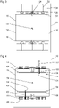
- FIG. 3 a view from above of the first elevator shaft 12 with a total of eight drive machines 34 is shown.
- the drive machines 34 are each drivingly connected to a traction sheave in the form of a deflection roller 30 over which a trotting means 26 runs.
- the reference numbers shown only once In each case four drive machines 34 are arranged on opposite sides of the elevator car 16 , with two drive machines 34 being arranged on different sides of the vertical guide rail 24 on each of the opposite sides of the elevator car 16 .
- Drive axles 52 of the drive machines 34 run parallel to one another, with a drive machine 34 being arranged on one side of the elevator car 16 coaxially to a drive machine 34 on the other side of the elevator car 16 .
- a car door, not shown, of the elevator car 16 is located on one or both free sides 54 of the elevator car 16, on which no drive machines 34 are arranged.
- the elevator control 36 controls two drive machines 34 on opposite sides in the same way or synchronously, so that the suspension elements 26 assigned to them also move or are displaced synchronously.
- Two drive machines 34 are controlled in the same way, which are arranged diagonally with respect to a center of gravity 56 of the elevator car, for example in 3 the upper, far left drive machine 34 and the lower, far right drive machine 34. With the eight drive machines 34, a total of four elevator cars 14, 16 can be displaced in the first elevator shaft 12 simultaneously and independently of one another.
- each coupling device 58 has a bolt 60 which can be extended and retracted in an actuation direction 62 which is oriented in the direction of the coupling elements 44 .
- the coupling device 58 has an actuating actuator 64, which can be embodied as an electric motor, for example.
- the bolt 60 can be moved together with the actuating actuator 64 horizontally and perpendicularly to the actuating direction 62 along a rail 66 by means of a positioning actuator 68, which is also designed as an electric motor, for example.
- the bolt 60 is first correctly positioned with respect to the corresponding coupling element 44 . Then the bolt 60 is extended, whereby the bolt 60 dips into the recess 48 of the coupling element 44 .
- a form-fitting connection is thus produced between the coupling device 58 and the coupling element 44 and thus between the elevator car 16 and the suspension element 26 .
- the elevator car 16 is displaced in the elevator shaft 12 as soon as the suspension element 26 is driven or displaced by the drive machine 34 .
- the elevator car 16 is coupled to two support means 26 which are arranged diagonally with respect to the center of gravity 56 of the elevator car. This takes place in that the elevator car 16 is coupled to coupling elements 44 which are arranged diagonally with respect to the center of gravity 56 of the elevator car 16 .
- Each coupling element 44 is guided by a guide 53 during displacement in the elevator shaft 12 .
- the guide 53 is arranged between each coupling element 44 and the elevator car 16 and runs through the entire elevator shaft 12.
- the Guides 53 prevent, in particular, a free coupling element 44, i.e. a coupling element 44 to which no elevator car 14, 16 is coupled, from striking a passing elevator car 14, 16.
- the bolts of the coupling devices cannot be displaced transversely to the direction of actuation.
- the coupling devices have separate bolts and actuating actuators for each coupling element.
- an elevator car it is also possible for an elevator car to have only one coupling device, so that an elevator car is coupled to only one suspension means for displacement in the elevator shaft. This is the case in particular when the drive machines and thus the suspension means are arranged on a side of the elevator car which is opposite the car door and thus the shaft doors.
- the elevator system 10 In addition to a first elevator shaft 12, it has a second elevator shaft 13, which is arranged parallel to the first elevator shaft 12.
- the second elevator shaft 13 is designed analogously to the first elevator shaft 12 .
- the relocation of the elevator cars 14, 16 in the second elevator shaft 13 is implemented analogously to the relocation in the first elevator shaft 12. In the first elevator shaft 12, the elevator cars 14, 16 are only displaced upwards and in the second elevator shaft 13 only downwards.
- FIG 5a is the first elevator car 14 in the first elevator shaft 12 at the lower end position 18. She is on her in the Figures 5a, 5b and 5c not shown coupling device to a first in which Figure 5a right coupling element 44 of the suspension element 26 is coupled.
- the first elevator car 14 has only one single, non-displaceable coupling device.
- the coupling device is arranged in such a way that it can be coupled to the right-hand coupling element 44 .
- the first elevator car 14 can thus only be coupled to the right-hand coupling element 44, so that the first elevator car 14 is assigned the right-hand coupling element 44.
- a second, in the Figure 5a The left-hand coupling element 44 of the suspension element 26 is arranged on the suspension element 26 in such a way that a coupling device of an elevator car located in the upper end position 22 could be uncoupled from the second coupling element 44 .
- a deflection roller 28, 30 is arranged in each case.
- the drive machine 34 drives the upper deflection roller 30 in a counterclockwise direction of movement, which is indicated by a directional arrow 69 .
- the first elevator car 14 is shifted between the lower end position 18 and the upper end position 22 to the upper end position 22 with possible intermediate stops at floors.
- the second is in the Figure 5a Left coupling element 44 shifted down.
- neither of the two coupling elements 44 comes into contact with one of the two deflection rollers 28, 30.
- the coupling elements 44 therefore neither touch one of the two deflection rollers 28, 30, nor are they guided around the deflection rollers 28, 30.
- the second elevator car 16 is located in the Figure 5a in the second elevator shaft 13 at the upper end position 22. She is in the Figures 5a, 5b and 5c not shown coupling device to a first in which Figure 5a left coupling element 44 of the suspension element 26 is coupled.
- the second elevator car 16 also has only a single, non-displaceable coupling device.
- the coupling device is arranged in such a way that it can be coupled to the left-hand coupling element 44 .
- the second elevator car 16 can thus only be coupled to the left-hand coupling element 44 , so that the left-hand coupling element 44 is assigned to the second elevator car 16 .
- a second, in the Figure 5a The right-hand coupling element 44 of the suspension element 26 is arranged on the suspension element 26 in such a way that a coupling device of an elevator car located in the lower end position 18 is uncoupled from the second coupling element 44 could.
- a deflection roller 28, 30 is arranged in each case.
- the drive machine 34 To move the second elevator car 16 downwards, the drive machine 34 also drives the upper deflection roller 30 counterclockwise.
- the second elevator car 16 is shifted between the upper end position 22 and the lower end position 18 to the lower end position 18 with possible intermediate stops at floors.
- the second Simultaneously with the shift of the first, in the Figure 5a left coupling element 44 down, the second is in the Figure 5a right coupling element 44 shifted upwards. During said displacement, neither of the two coupling elements 44 comes into contact with one of the two deflection rollers 28, 30.
- the elevator system 10 has a first, upper transfer device 70 by means of which the first elevator car 14 can be shifted from the first elevator shaft 12 into the second elevator shaft 13 at the upper end position 22 .
- the first transfer device 70 has a vertical guide rail piece 72 which guides the first elevator car 14 in the first transfer device 70 .
- the first transfer device 70 is positioned such that the guide rail piece 72 forms a section of the vertical guide rail 24 of the first elevator shaft 12, by which the first elevator car 14 is guided during displacement in the first elevator shaft 12.
- the first elevator car 14 has a braking device 74 with which the first elevator car 14 is temporarily fixed to the guide rail piece 72 integrated in the first transfer device 70 during the displacement between the first elevator shaft 12 and the second elevator shaft 13 .
- the elevator system 10 also has a second, lower transfer device 76 for moving the second elevator car 16 in the lower end position 18 from the second elevator shaft 13 into the first elevator shaft 12.
- the second, lower transfer device 76 is designed analogously to the first, upper transfer device 70.
- the second elevator car 16 also has a braking device 74.
- the transfer devices 70, 76 can in particular corresponding to the transfer devices in the form of horizontal displacement units EP 2219985 B1 be executed.
- FIG 5c the situation after the displacement of the two elevator cars 14, 16 is shown.
- the first elevator car 14 is positioned in the second elevator shaft 13 at the upper end position 22 and the second elevator car 16 is positioned in the first elevator shaft 12 at the lower end position 18 .
- the drive machine 34 To move the second elevator car 16 upwards, the drive machine 34 now drives the upper deflection roller 30 in a clockwise direction.
- the drive machine 34 is thus controlled by the elevator control in such a way that the direction of movement of the suspension element 26 is reversed for the next displacement of an elevator car when an elevator car has reached the lower end position or the upper end position.
- the second elevator car 16 is shifted between the lower end position 18 and the upper end position 22 to the upper end position 22 with possible intermediate stops at floors. Simultaneously with the shift of the second, in the Figure 5c left coupling element 44 upwards, the first is in the Figure 5c right coupling element 44 shifted downwards.
- the first elevator car 14 is located in the Figure 5c in the second elevator shaft 13 the upper end position 22. She is on her coupling device to the second, in which Figure 5c right coupling element 44 of the suspension element 26 is coupled.
- the first in the Figure 5c The left-hand coupling element 44 of the suspension element 26 is arranged on the suspension element 26 in such a way that a coupling device of an elevator car located in the lower end position 18 could be uncoupled from the second coupling element 44 .
- the drive machine 34 In order to move the first elevator car 14 downwards, the drive machine 34 now also drives the upper deflection roller 30 in a clockwise direction. It takes place compared to Figure 5a ie a reversal of the direction of movement of the suspension element 26 also takes place.
- the first elevator car 14 is shifted between the upper end position 22 and the lower end position 18 to the lower end position 18 with possible intermediate stops at floors. Simultaneously with the shift of the second, in the Figure 5c right coupling element 44 down, the first is in the Figure 5c left coupling element 44 shifted upwards.
- the elevator system it is also possible for the elevator system to have a third elevator shaft in which elevator cars that are currently not required can be parked.
Claims (15)
- Système d'ascenseur comportant- une première cabine d'ascenseur (14) et une seconde cabine d'ascenseur (16) qui peuvent être déplacées dans une direction verticale dans une première cage d'ascenseur (12),- un moyen de support (26) autonome guidé autour d'un galet de renvoi inférieur (28) et d'un galet de renvoi supérieur (30),- une machine d'entraînement (34) associée au moyen de support (26) et- un dispositif d'accouplement (58) commandable disposé sur la première cabine d'ascenseur (14) et un dispositif d'accouplement (58) commandable disposé sur la seconde cabine d'ascenseur (16),dans lequel le moyen de support (26) présente un premier et un second éléments d'accouplement (44) auxquels un dispositif d'accouplement (58) peut être accouplé et désaccouplé, moyennant quoi une liaison d'entraînement peut être établie et détachée entre la cabine d'ascenseur (14, 16) respective et le moyen de support (26) et une cabine d'ascenseur (14, 16) accouplée peut être déplacée dans une première cage d'ascenseur (12) au moyen du moyen de support (26) pouvant être entraîné par la machine d'entraînement (34) respective,
caractérisé en ce que
les deux éléments d'accouplement (44) du moyen de support (26) sont disposés de telle sorte que lorsque la première cabine d'ascenseur (14), qui est accouplée au moyen de support (26) par l'intermédiaire d'un élément d'accouplement (44), est déplacée d'une position finale inférieure (18) à une position finale supérieure (22) ou inversement, aucun élément d'accouplement (44) n'est guidé autour d'un galet de renvoi (28, 30). - Système d'ascenseur selon la revendication 1,
caractérisé en ce que
les deux éléments d'accouplement (44) du moyen de support (26) sont disposés de telle sorte que lorsque la première cabine d'ascenseur (14), qui est accouplée au moyen de support (26) par l'intermédiaire d'un élément d'accouplement (44), est déplacée d'une position finale inférieure (18) à une position finale supérieure (22) ou inversement, aucun élément d'accouplement (44) n'entre en contact avec un galet de renvoi (28, 30). - Système d'ascenseur selon la revendication 1 ou 2,
caractérisé en ce que
les deux éléments d'accouplement (44) du moyen de support (26) sont disposés de telle sorte que lorsque la première cabine d'ascenseur (14), qui est accouplée au moyen de support (26) par l'intermédiaire d'un élément d'accouplement (44), a atteint la position finale supérieure (22), l'autre élément d'accouplement (44) est positionné de telle manière que le dispositif d'accouplement (58) associé à la seconde cabine d'ascenseur (16) de la seconde cabine d'ascenseur (16) disposée dans la position finale inférieure (18) peut s'accoupler à l'autre élément d'accouplement (44). - Système d'ascenseur selon la revendication 1, 2 ou 3,
caractérisé en ce que
la machine d'entraînement (34) est commandée par une commande d'ascenseur (36), laquelle est prévue pour inverser une direction de mouvement (69) du moyen de support (26) pour le prochain déplacement d'une cabine d'ascenseur (14, 16) lorsqu'une cabine d'ascenseur (14, 16) a atteint la position finale inférieure (18) ou la position finale supérieure (22). - Système d'ascenseur selon l'une des revendications 1 à 4,
caractérisé par
un autre moyen de support (26) comportant deux éléments d'accouplement (44) disposés à distance l'un de l'autre dans la direction verticale et une autre machine d'entraînement (34) associée à l'autre moyen de support (26). - Système d'ascenseur selon l'une des revendications 1 à 5,
caractérisé en ce que
un élément d'accouplement (44) de chaque moyen de support (26) est conçu comme un élément de liaison qui relie deux extrémités libres (42) de parties de moyen de support (38, 40) l'une à l'autre. - Système d'ascenseur selon la revendication 6,
caractérisé en ce que
les deux éléments d'accouplement (44) de chaque moyen de support (26) sont conçus comme des éléments de liaison. - Système d'ascenseur selon l'une des revendications 1 à 7,
caractérisé en ce que
le moyen de support (26) est réalisé sous forme de courroie. - Système d'ascenseur selon l'une des revendications 1 à 8,
caractérisé en ce que
les éléments d'accouplement (44) sont guidés lors d'un déplacement dans la première cage d'ascenseur (12). - Système d'ascenseur selon l'une des revendications 1 à 9,
caractérisé en ce que
chaque cabine d'ascenseur (14, 16) présente deux dispositifs d'accouplement (58) qui sont prévus pour être simultanément accouplés à des éléments d'accouplement (44) de deux moyens de support (26) différents. - Système d'ascenseur selon la revendication 10,
caractérisé en ce que
les deux dispositifs d'accouplement (58) sont disposés sur des côtés opposés de la cabine d'ascenseur (14, 16). - Système d'ascenseur selon la revendication 11,
caractérisé en ce que
les deux dispositifs d'accouplement (58) sont prévus pour être accouplés à respectivement un élément d'accouplement (44) d'un moyen de support (26) à des positions diagonalement opposées. - Système d'ascenseur selon l'une des revendications 1 à 12,
caractérisé en ce quela première cabine d'ascenseur (14) et la seconde cabine d'ascenseur (16) peuvent également être déplacées dans la direction verticale dans une seconde cage d'ascenseur (13) disposée parallèlement à la première cage d'ascenseur (12), etle système d'ascenseur (10) présente- un premier dispositif de transfert (70) au moyen duquel des cabines d'ascenseur (14, 16) peuvent être déplacées de la première cage d'ascenseur (12) à la seconde cage d'ascenseur (13) et- un second dispositif de transfert (76) au moyen duquel des cabines d'ascenseur (14, 16) peuvent être déplacées de la seconde cage d'ascenseur (13) à la première cage d'ascenseur (12),dans lequel un déplacement des cabines d'ascenseur (14, 16) dans la seconde cage d'ascenseur (13) est réalisé de manière analogue au déplacement dans la première cage d'ascenseur (12). - Système d'ascenseur selon la revendication 13,
caractérisé en ce que
les cabines d'ascenseur (14, 16), dans la première cage d'ascenseur (12), ne sont déplacées que de bas en haut et, dans la seconde cage d'ascenseur (13), ne sont déplacées que de haut en bas. - Système d'ascenseur selon la revendication 13 ou 14,
caractérisé en ce que
respectivement le même nombre de moyens de support (26) comportant respectivement deux éléments d'accouplement (44) sont disposés dans la première cage d'ascenseur (12) et dans la seconde cage d'ascenseur (13), et un nombre de cabines d'ascenseur (14, 16) est au maximum égal à un nombre total des moyens de support (26).
Applications Claiming Priority (2)
| Application Number | Priority Date | Filing Date | Title |
|---|---|---|---|
| EP17186585 | 2017-08-17 | ||
| PCT/EP2018/070656 WO2019034405A1 (fr) | 2017-08-17 | 2018-07-31 | Système d'ascenseur |
Publications (2)
| Publication Number | Publication Date |
|---|---|
| EP3668810A1 EP3668810A1 (fr) | 2020-06-24 |
| EP3668810B1 true EP3668810B1 (fr) | 2022-06-22 |
Family
ID=59649573
Family Applications (2)
| Application Number | Title | Priority Date | Filing Date |
|---|---|---|---|
| EP18745596.9A Active EP3681835B1 (fr) | 2017-08-17 | 2018-07-25 | Système élévateur |
| EP18743833.8A Active EP3668810B1 (fr) | 2017-08-17 | 2018-07-31 | Système élévateur |
Family Applications Before (1)
| Application Number | Title | Priority Date | Filing Date |
|---|---|---|---|
| EP18745596.9A Active EP3681835B1 (fr) | 2017-08-17 | 2018-07-25 | Système élévateur |
Country Status (6)
| Country | Link |
|---|---|
| US (2) | US11623845B2 (fr) |
| EP (2) | EP3681835B1 (fr) |
| CN (2) | CN110997543B (fr) |
| AU (2) | AU2018317641B2 (fr) |
| SG (2) | SG11202000750VA (fr) |
| WO (2) | WO2019034381A1 (fr) |
Families Citing this family (5)
| Publication number | Priority date | Publication date | Assignee | Title |
|---|---|---|---|---|
| SG11202000750VA (en) * | 2017-08-17 | 2020-02-27 | Inventio Ag | Elevator system |
| WO2020164965A1 (fr) * | 2019-02-12 | 2020-08-20 | Inventio Ag | Système d'ascenseur |
| US11737431B2 (en) * | 2020-05-29 | 2023-08-29 | Denise Michelle Berger | Bird feeder support system |
| US11665974B2 (en) * | 2021-01-27 | 2023-05-30 | International Business Machines Corporation | MRAM containing magnetic top contact |
| EP4180379B1 (fr) * | 2021-11-12 | 2024-05-15 | Norvento Tecnología, S.L.U. | Système et procédé de déplacement vertical de poids |
Family Cites Families (40)
| Publication number | Priority date | Publication date | Assignee | Title |
|---|---|---|---|---|
| US3910383A (en) * | 1974-04-22 | 1975-10-07 | Vladimir Friedl | Manlift |
| DE2542262A1 (de) * | 1975-09-23 | 1977-03-24 | Ernst Schmid | Fahrtreppe |
| JP2665686B2 (ja) * | 1989-12-05 | 1997-10-22 | 眸 島田 | 垂直型交通機関 |
| JP3182320B2 (ja) * | 1995-07-17 | 2001-07-03 | 株式会社日立製作所 | つかみ替え式循環型エレベータ |
| JPH09194159A (ja) * | 1996-01-17 | 1997-07-29 | Mitsubishi Denki Bill Techno Service Kk | ロープ孔塞ぎ装置 |
| JPH1059659A (ja) * | 1996-08-22 | 1998-03-03 | Tetsuzo Shibuya | エレベーター |
| JP2000086121A (ja) * | 1998-09-09 | 2000-03-28 | Ohbayashi Corp | エレベータ装置 |
| EP1367018B1 (fr) * | 2002-05-27 | 2010-10-06 | Inventio AG | Ascenseur comprenant plusiers cabines auto-motrice et au moins trois gaines d'ascenseur disposé côte à côte |
| DE10300992A1 (de) * | 2003-01-14 | 2004-07-22 | Aufzugswerke M. Schmitt & Sohn Gmbh & Co. | Aufzug mit getrennter Fahrkorbaufhängung |
| JP2005132527A (ja) * | 2003-10-29 | 2005-05-26 | Hitachi Ltd | マルチカーエレベータ |
| JP2005200162A (ja) * | 2004-01-15 | 2005-07-28 | Toshiba Elevator Co Ltd | エレベータの調速装置 |
| JP4301105B2 (ja) * | 2004-07-26 | 2009-07-22 | 株式会社日立製作所 | エレベーター装置 |
| ZA200506660B (en) * | 2004-09-13 | 2006-05-31 | Inventio Ag | Belt end connection for fastening a belt end in a lift installation and method for protecting and checking a belt end connection in a lift installation |
| JP4543868B2 (ja) * | 2004-10-15 | 2010-09-15 | 株式会社日立製作所 | マルチカーエレベータ |
| EP1693331A1 (fr) * | 2005-02-17 | 2006-08-23 | Inventio Ag | Ascenseur muni de plusieurs gaines et avec cabines pouvant être couplées et découplées à l'entraînement selectionné. |
| JP4552793B2 (ja) * | 2005-07-22 | 2010-09-29 | 株式会社日立製作所 | マルチカーエレベータの安全システム |
| US7857103B2 (en) * | 2006-12-14 | 2010-12-28 | Inventio Ag | Elevator system |
| US7661513B2 (en) | 2006-12-14 | 2010-02-16 | Inventio Ag | Dual-car elevator system with common counterweight |
| MY149179A (en) * | 2006-12-14 | 2013-07-31 | Inventio Ag | Lift system |
| EP2070860A1 (fr) * | 2007-12-11 | 2009-06-17 | Inventio Ag | Système d'ascenseur doté de cabines d'ascenseur mobiles verticalement et horizontalement |
| EP2072445A1 (fr) * | 2007-12-21 | 2009-06-24 | Inventio Ag | Procédé de fonctionnement pour un ascenseur doté de deux cabines et d'un contrepoids |
| WO2010072656A1 (fr) | 2008-12-26 | 2010-07-01 | Inventio Ag | Cage d'ascenseur à plusieurs cabines et à utilisation améliorée de la cage |
| EP2512968B1 (fr) * | 2009-12-15 | 2015-04-29 | Inventio AG | Installation d'ascenseur à double cabine |
| FR2958635B1 (fr) * | 2010-04-12 | 2012-08-31 | Fernand Voillot | Monte-charge et batiment equipe d'un monte-charge. |
| DE102010030436A1 (de) * | 2010-06-23 | 2011-12-29 | Thyssenkrupp Elevator Ag | Aufzuganlage |
| US8430210B2 (en) * | 2011-01-19 | 2013-04-30 | Smart Lifts, Llc | System having multiple cabs in an elevator shaft |
| JP2012246116A (ja) * | 2011-05-30 | 2012-12-13 | Mitsubishi Electric Corp | エレベータ装置及びその非常止め試験方法 |
| FI124330B (fi) * | 2012-01-02 | 2014-06-30 | Kone Corp | Hissijärjestely ja menetelmä hissijärjestelyn uudelleenasettelemiseksi |
| EP2928805B1 (fr) * | 2012-12-10 | 2017-01-11 | Inventio AG | Ascenseur à biplan avec distance intercabine réglable |
| TWI568659B (zh) * | 2013-07-26 | 2017-02-01 | 斯馬特利福特有限責任公司 | 具有在電梯井之不同部份中獨立移動之複數個電梯廂及配重塊之系統 |
| DE102013110790A1 (de) | 2013-09-30 | 2015-04-02 | Thyssenkrupp Elevator Ag | Aufzuganlage |
| DE102013110778A1 (de) * | 2013-09-30 | 2015-04-02 | Thyssenkrupp Elevator Ag | Aufzuganlage |
| DE102013110792A1 (de) * | 2013-09-30 | 2015-04-02 | Thyssenkrupp Elevator Ag | Aufzuganlage |
| DE102013110791A1 (de) * | 2013-09-30 | 2015-04-02 | Thyssenkrupp Elevator Ag | Aufzuganlage |
| US9758347B2 (en) * | 2014-12-02 | 2017-09-12 | ThyssenKrupp Elevator AG; ThyssenKrupp AG | Arrangement and method to move at least two elevator cars independently in at least one hoistway |
| CN107000992A (zh) * | 2014-12-05 | 2017-08-01 | 通力股份公司 | 在同一井道中具有多个轿厢的电梯装置 |
| CN108602643A (zh) * | 2015-11-30 | 2018-09-28 | 通力股份公司 | 可调式多轿厢电梯系统 |
| DE102017113571A1 (de) * | 2017-06-20 | 2018-12-20 | Thyssenkrupp Ag | Aufzugsystem |
| SG11202000750VA (en) * | 2017-08-17 | 2020-02-27 | Inventio Ag | Elevator system |
| WO2020164965A1 (fr) * | 2019-02-12 | 2020-08-20 | Inventio Ag | Système d'ascenseur |
-
2018
- 2018-07-25 SG SG11202000750VA patent/SG11202000750VA/en unknown
- 2018-07-25 EP EP18745596.9A patent/EP3681835B1/fr active Active
- 2018-07-25 WO PCT/EP2018/070099 patent/WO2019034381A1/fr active Search and Examination
- 2018-07-25 AU AU2018317641A patent/AU2018317641B2/en active Active
- 2018-07-25 CN CN201880053332.2A patent/CN110997543B/zh active Active
- 2018-07-25 US US16/634,198 patent/US11623845B2/en active Active
- 2018-07-31 AU AU2018319105A patent/AU2018319105B2/en active Active
- 2018-07-31 EP EP18743833.8A patent/EP3668810B1/fr active Active
- 2018-07-31 WO PCT/EP2018/070656 patent/WO2019034405A1/fr unknown
- 2018-07-31 CN CN201880053333.7A patent/CN110997544B/zh active Active
- 2018-07-31 SG SG11202000756UA patent/SG11202000756UA/en unknown
- 2018-07-31 US US16/634,902 patent/US11535493B2/en active Active
Also Published As
| Publication number | Publication date |
|---|---|
| EP3681835A1 (fr) | 2020-07-22 |
| AU2018317641B2 (en) | 2021-09-30 |
| WO2019034381A1 (fr) | 2019-02-21 |
| SG11202000756UA (en) | 2020-02-27 |
| AU2018317641A1 (en) | 2020-03-05 |
| EP3681835B1 (fr) | 2022-08-31 |
| EP3668810A1 (fr) | 2020-06-24 |
| US20200231410A1 (en) | 2020-07-23 |
| CN110997544B (zh) | 2021-06-01 |
| CN110997544A (zh) | 2020-04-10 |
| US20200180911A1 (en) | 2020-06-11 |
| SG11202000750VA (en) | 2020-02-27 |
| CN110997543A (zh) | 2020-04-10 |
| WO2019034405A1 (fr) | 2019-02-21 |
| AU2018319105B2 (en) | 2021-09-30 |
| CN110997543B (zh) | 2022-04-15 |
| US11535493B2 (en) | 2022-12-27 |
| AU2018319105A1 (en) | 2020-03-05 |
| US11623845B2 (en) | 2023-04-11 |
Similar Documents
| Publication | Publication Date | Title |
|---|---|---|
| EP3668810B1 (fr) | Système élévateur | |
| EP3122680B1 (fr) | Système d'ascenseur | |
| EP1580156B1 (fr) | Ascenseur comprenant des moyens de transmission sous forme de courroies trapézoidales, en particulier comprenant des courroies trapézoidales dentées, comme moyens de support et /ou de traction | |
| EP2219985B1 (fr) | Système d'ascenseur avec cabines d'ascenseur mobiles dans les sens vertical et horizontal | |
| EP2398729B1 (fr) | Installation d'ascenseur présentant un mobile à plusieurs étages | |
| EP2082983B1 (fr) | Installation d'ascenseur | |
| EP3807205B1 (fr) | Procédé de construction d'une installation d'ascenseur | |
| EP2928805B1 (fr) | Ascenseur à biplan avec distance intercabine réglable | |
| EP1935829A1 (fr) | Ascenseur avec deux cabines dans une gaine | |
| DE10024973B4 (de) | Liftsystem für den vertikalen Transport von Nutzlasten in einem Luftfahrzeug | |
| EP2512968B1 (fr) | Installation d'ascenseur à double cabine | |
| EP3227216B1 (fr) | Ascenseur | |
| EP3931141B1 (fr) | Système d'ascenseur | |
| EP3924284B1 (fr) | Système d'ascenseur | |
| EP3114067B1 (fr) | Entraînement à courroie multiple pour une installation d'ascenseur | |
| AT515346A2 (de) | Aufzuganlage | |
| EP3924285B1 (fr) | Système d'ascenseur | |
| DE10200874A1 (de) | Aufzug zur Beförderung von Personen und Lasten | |
| EP3621909B1 (fr) | Systeme d'ascenseure avec deux puits | |
| EP2468674A1 (fr) | Installation d'ascenseur à biplan | |
| DE19962542B4 (de) | Plattform zur Aufnahme eines Kraftfahrzeuges | |
| EP3705443A1 (fr) | Installation d'ascenseur à moyen de traction équilibré | |
| EP1671917A1 (fr) | Système d'ascenseur avec porte d'ascenseur et dispositif de verrouillage | |
| WO2023011771A1 (fr) | Système de levage sans salle des machines | |
| EP3124424A1 (fr) | Dispositif de suspension de support dote d'un dispositif a bascule presentant des poulies de renvoi pour un ascenseur |
Legal Events
| Date | Code | Title | Description |
|---|---|---|---|
| STAA | Information on the status of an ep patent application or granted ep patent |
Free format text: STATUS: UNKNOWN |
|
| STAA | Information on the status of an ep patent application or granted ep patent |
Free format text: STATUS: THE INTERNATIONAL PUBLICATION HAS BEEN MADE |
|
| PUAI | Public reference made under article 153(3) epc to a published international application that has entered the european phase |
Free format text: ORIGINAL CODE: 0009012 |
|
| STAA | Information on the status of an ep patent application or granted ep patent |
Free format text: STATUS: REQUEST FOR EXAMINATION WAS MADE |
|
| 17P | Request for examination filed |
Effective date: 20200115 |
|
| AK | Designated contracting states |
Kind code of ref document: A1 Designated state(s): AL AT BE BG CH CY CZ DE DK EE ES FI FR GB GR HR HU IE IS IT LI LT LU LV MC MK MT NL NO PL PT RO RS SE SI SK SM TR |
|
| AX | Request for extension of the european patent |
Extension state: BA ME |
|
| DAV | Request for validation of the european patent (deleted) | ||
| DAX | Request for extension of the european patent (deleted) | ||
| GRAP | Despatch of communication of intention to grant a patent |
Free format text: ORIGINAL CODE: EPIDOSNIGR1 |
|
| STAA | Information on the status of an ep patent application or granted ep patent |
Free format text: STATUS: GRANT OF PATENT IS INTENDED |
|
| INTG | Intention to grant announced |
Effective date: 20220316 |
|
| GRAS | Grant fee paid |
Free format text: ORIGINAL CODE: EPIDOSNIGR3 |
|
| GRAA | (expected) grant |
Free format text: ORIGINAL CODE: 0009210 |
|
| STAA | Information on the status of an ep patent application or granted ep patent |
Free format text: STATUS: THE PATENT HAS BEEN GRANTED |
|
| AK | Designated contracting states |
Kind code of ref document: B1 Designated state(s): AL AT BE BG CH CY CZ DE DK EE ES FI FR GB GR HR HU IE IS IT LI LT LU LV MC MK MT NL NO PL PT RO RS SE SI SK SM TR |
|
| REG | Reference to a national code |
Ref country code: GB Ref legal event code: FG4D Free format text: NOT ENGLISH |
|
| REG | Reference to a national code |
Ref country code: CH Ref legal event code: EP |
|
| REG | Reference to a national code |
Ref country code: DE Ref legal event code: R096 Ref document number: 502018009987 Country of ref document: DE |
|
| REG | Reference to a national code |
Ref country code: AT Ref legal event code: REF Ref document number: 1499673 Country of ref document: AT Kind code of ref document: T Effective date: 20220715 |
|
| REG | Reference to a national code |
Ref country code: IE Ref legal event code: FG4D Free format text: LANGUAGE OF EP DOCUMENT: GERMAN |
|
| RAP4 | Party data changed (patent owner data changed or rights of a patent transferred) |
Owner name: INVENTIO AG |
|
| REG | Reference to a national code |
Ref country code: LT Ref legal event code: MG9D |
|
| REG | Reference to a national code |
Ref country code: NL Ref legal event code: MP Effective date: 20220622 |
|
| PG25 | Lapsed in a contracting state [announced via postgrant information from national office to epo] |
Ref country code: SE Free format text: LAPSE BECAUSE OF FAILURE TO SUBMIT A TRANSLATION OF THE DESCRIPTION OR TO PAY THE FEE WITHIN THE PRESCRIBED TIME-LIMIT Effective date: 20220622 Ref country code: NO Free format text: LAPSE BECAUSE OF FAILURE TO SUBMIT A TRANSLATION OF THE DESCRIPTION OR TO PAY THE FEE WITHIN THE PRESCRIBED TIME-LIMIT Effective date: 20220922 Ref country code: LT Free format text: LAPSE BECAUSE OF FAILURE TO SUBMIT A TRANSLATION OF THE DESCRIPTION OR TO PAY THE FEE WITHIN THE PRESCRIBED TIME-LIMIT Effective date: 20220622 Ref country code: HR Free format text: LAPSE BECAUSE OF FAILURE TO SUBMIT A TRANSLATION OF THE DESCRIPTION OR TO PAY THE FEE WITHIN THE PRESCRIBED TIME-LIMIT Effective date: 20220622 Ref country code: GR Free format text: LAPSE BECAUSE OF FAILURE TO SUBMIT A TRANSLATION OF THE DESCRIPTION OR TO PAY THE FEE WITHIN THE PRESCRIBED TIME-LIMIT Effective date: 20220923 Ref country code: FI Free format text: LAPSE BECAUSE OF FAILURE TO SUBMIT A TRANSLATION OF THE DESCRIPTION OR TO PAY THE FEE WITHIN THE PRESCRIBED TIME-LIMIT Effective date: 20220622 Ref country code: BG Free format text: LAPSE BECAUSE OF FAILURE TO SUBMIT A TRANSLATION OF THE DESCRIPTION OR TO PAY THE FEE WITHIN THE PRESCRIBED TIME-LIMIT Effective date: 20220922 |
|
| PG25 | Lapsed in a contracting state [announced via postgrant information from national office to epo] |
Ref country code: RS Free format text: LAPSE BECAUSE OF FAILURE TO SUBMIT A TRANSLATION OF THE DESCRIPTION OR TO PAY THE FEE WITHIN THE PRESCRIBED TIME-LIMIT Effective date: 20220622 Ref country code: LV Free format text: LAPSE BECAUSE OF FAILURE TO SUBMIT A TRANSLATION OF THE DESCRIPTION OR TO PAY THE FEE WITHIN THE PRESCRIBED TIME-LIMIT Effective date: 20220622 |
|
| PG25 | Lapsed in a contracting state [announced via postgrant information from national office to epo] |
Ref country code: NL Free format text: LAPSE BECAUSE OF FAILURE TO SUBMIT A TRANSLATION OF THE DESCRIPTION OR TO PAY THE FEE WITHIN THE PRESCRIBED TIME-LIMIT Effective date: 20220622 |
|
| PG25 | Lapsed in a contracting state [announced via postgrant information from national office to epo] |
Ref country code: SM Free format text: LAPSE BECAUSE OF FAILURE TO SUBMIT A TRANSLATION OF THE DESCRIPTION OR TO PAY THE FEE WITHIN THE PRESCRIBED TIME-LIMIT Effective date: 20220622 Ref country code: SK Free format text: LAPSE BECAUSE OF FAILURE TO SUBMIT A TRANSLATION OF THE DESCRIPTION OR TO PAY THE FEE WITHIN THE PRESCRIBED TIME-LIMIT Effective date: 20220622 Ref country code: RO Free format text: LAPSE BECAUSE OF FAILURE TO SUBMIT A TRANSLATION OF THE DESCRIPTION OR TO PAY THE FEE WITHIN THE PRESCRIBED TIME-LIMIT Effective date: 20220622 Ref country code: PT Free format text: LAPSE BECAUSE OF FAILURE TO SUBMIT A TRANSLATION OF THE DESCRIPTION OR TO PAY THE FEE WITHIN THE PRESCRIBED TIME-LIMIT Effective date: 20221024 Ref country code: ES Free format text: LAPSE BECAUSE OF FAILURE TO SUBMIT A TRANSLATION OF THE DESCRIPTION OR TO PAY THE FEE WITHIN THE PRESCRIBED TIME-LIMIT Effective date: 20220622 Ref country code: EE Free format text: LAPSE BECAUSE OF FAILURE TO SUBMIT A TRANSLATION OF THE DESCRIPTION OR TO PAY THE FEE WITHIN THE PRESCRIBED TIME-LIMIT Effective date: 20220622 Ref country code: CZ Free format text: LAPSE BECAUSE OF FAILURE TO SUBMIT A TRANSLATION OF THE DESCRIPTION OR TO PAY THE FEE WITHIN THE PRESCRIBED TIME-LIMIT Effective date: 20220622 |
|
| PG25 | Lapsed in a contracting state [announced via postgrant information from national office to epo] |
Ref country code: PL Free format text: LAPSE BECAUSE OF FAILURE TO SUBMIT A TRANSLATION OF THE DESCRIPTION OR TO PAY THE FEE WITHIN THE PRESCRIBED TIME-LIMIT Effective date: 20220622 Ref country code: IS Free format text: LAPSE BECAUSE OF FAILURE TO SUBMIT A TRANSLATION OF THE DESCRIPTION OR TO PAY THE FEE WITHIN THE PRESCRIBED TIME-LIMIT Effective date: 20221022 |
|
| REG | Reference to a national code |
Ref country code: DE Ref legal event code: R097 Ref document number: 502018009987 Country of ref document: DE |
|
| REG | Reference to a national code |
Ref country code: BE Ref legal event code: MM Effective date: 20220731 |
|
| PG25 | Lapsed in a contracting state [announced via postgrant information from national office to epo] |
Ref country code: MC Free format text: LAPSE BECAUSE OF FAILURE TO SUBMIT A TRANSLATION OF THE DESCRIPTION OR TO PAY THE FEE WITHIN THE PRESCRIBED TIME-LIMIT Effective date: 20220622 Ref country code: AL Free format text: LAPSE BECAUSE OF FAILURE TO SUBMIT A TRANSLATION OF THE DESCRIPTION OR TO PAY THE FEE WITHIN THE PRESCRIBED TIME-LIMIT Effective date: 20220622 |
|
| PG25 | Lapsed in a contracting state [announced via postgrant information from national office to epo] |
Ref country code: LU Free format text: LAPSE BECAUSE OF NON-PAYMENT OF DUE FEES Effective date: 20220731 Ref country code: DK Free format text: LAPSE BECAUSE OF FAILURE TO SUBMIT A TRANSLATION OF THE DESCRIPTION OR TO PAY THE FEE WITHIN THE PRESCRIBED TIME-LIMIT Effective date: 20220622 |
|
| PLBE | No opposition filed within time limit |
Free format text: ORIGINAL CODE: 0009261 |
|
| STAA | Information on the status of an ep patent application or granted ep patent |
Free format text: STATUS: NO OPPOSITION FILED WITHIN TIME LIMIT |
|
| 26N | No opposition filed |
Effective date: 20230323 |
|
| PG25 | Lapsed in a contracting state [announced via postgrant information from national office to epo] |
Ref country code: BE Free format text: LAPSE BECAUSE OF NON-PAYMENT OF DUE FEES Effective date: 20220731 |
|
| PG25 | Lapsed in a contracting state [announced via postgrant information from national office to epo] |
Ref country code: IE Free format text: LAPSE BECAUSE OF NON-PAYMENT OF DUE FEES Effective date: 20220731 |
|
| PG25 | Lapsed in a contracting state [announced via postgrant information from national office to epo] |
Ref country code: SI Free format text: LAPSE BECAUSE OF FAILURE TO SUBMIT A TRANSLATION OF THE DESCRIPTION OR TO PAY THE FEE WITHIN THE PRESCRIBED TIME-LIMIT Effective date: 20220622 |
|
| PGFP | Annual fee paid to national office [announced via postgrant information from national office to epo] |
Ref country code: GB Payment date: 20230725 Year of fee payment: 6 Ref country code: CH Payment date: 20230801 Year of fee payment: 6 |
|
| PGFP | Annual fee paid to national office [announced via postgrant information from national office to epo] |
Ref country code: FR Payment date: 20230725 Year of fee payment: 6 Ref country code: DE Payment date: 20230731 Year of fee payment: 6 |
|
| PG25 | Lapsed in a contracting state [announced via postgrant information from national office to epo] |
Ref country code: IT Free format text: LAPSE BECAUSE OF FAILURE TO SUBMIT A TRANSLATION OF THE DESCRIPTION OR TO PAY THE FEE WITHIN THE PRESCRIBED TIME-LIMIT Effective date: 20220622 |
|
| PG25 | Lapsed in a contracting state [announced via postgrant information from national office to epo] |
Ref country code: MK Free format text: LAPSE BECAUSE OF FAILURE TO SUBMIT A TRANSLATION OF THE DESCRIPTION OR TO PAY THE FEE WITHIN THE PRESCRIBED TIME-LIMIT Effective date: 20220622 Ref country code: CY Free format text: LAPSE BECAUSE OF FAILURE TO SUBMIT A TRANSLATION OF THE DESCRIPTION OR TO PAY THE FEE WITHIN THE PRESCRIBED TIME-LIMIT Effective date: 20220622 |