EP3668810B1 - Elevator system - Google Patents
Elevator system Download PDFInfo
- Publication number
- EP3668810B1 EP3668810B1 EP18743833.8A EP18743833A EP3668810B1 EP 3668810 B1 EP3668810 B1 EP 3668810B1 EP 18743833 A EP18743833 A EP 18743833A EP 3668810 B1 EP3668810 B1 EP 3668810B1
- Authority
- EP
- European Patent Office
- Prior art keywords
- elevator
- coupling
- elevator car
- support means
- shaft
- Prior art date
- Legal status (The legal status is an assumption and is not a legal conclusion. Google has not performed a legal analysis and makes no representation as to the accuracy of the status listed.)
- Active
Links
- 230000008878 coupling Effects 0.000 claims description 233
- 238000010168 coupling process Methods 0.000 claims description 233
- 238000005859 coupling reaction Methods 0.000 claims description 233
- 239000000725 suspension Substances 0.000 description 139
- 238000006073 displacement reaction Methods 0.000 description 24
- 230000005484 gravity Effects 0.000 description 5
- 238000009434 installation Methods 0.000 description 3
- 239000012209 synthetic fiber Substances 0.000 description 2
- 229920002994 synthetic fiber Polymers 0.000 description 2
- 238000010276 construction Methods 0.000 description 1
- 230000009977 dual effect Effects 0.000 description 1
- 239000004744 fabric Substances 0.000 description 1
- 239000002184 metal Substances 0.000 description 1
- 230000010355 oscillation Effects 0.000 description 1
- 239000003380 propellant Substances 0.000 description 1
- 230000002787 reinforcement Effects 0.000 description 1
- 230000001360 synchronised effect Effects 0.000 description 1
Images


Classifications
-
- B—PERFORMING OPERATIONS; TRANSPORTING
- B66—HOISTING; LIFTING; HAULING
- B66B—ELEVATORS; ESCALATORS OR MOVING WALKWAYS
- B66B9/00—Kinds or types of lifts in, or associated with, buildings or other structures
- B66B9/003—Kinds or types of lifts in, or associated with, buildings or other structures for lateral transfer of car or frame, e.g. between vertical hoistways or to/from a parking position
-
- B—PERFORMING OPERATIONS; TRANSPORTING
- B66—HOISTING; LIFTING; HAULING
- B66B—ELEVATORS; ESCALATORS OR MOVING WALKWAYS
- B66B11/00—Main component parts of lifts in, or associated with, buildings or other structures
- B66B11/0065—Roping
- B66B11/008—Roping with hoisting rope or cable operated by frictional engagement with a winding drum or sheave
- B66B11/0095—Roping with hoisting rope or cable operated by frictional engagement with a winding drum or sheave where multiple cars drive in the same hoist way
-
- B—PERFORMING OPERATIONS; TRANSPORTING
- B66—HOISTING; LIFTING; HAULING
- B66B—ELEVATORS; ESCALATORS OR MOVING WALKWAYS
- B66B2201/00—Aspects of control systems of elevators
- B66B2201/30—Details of the elevator system configuration
Definitions
- the invention relates to an elevator system having the features of the preamble of claim 1.
- the EP 2219985 B1 describes an elevator system with two elevator cars that can be displaced in a vertical direction in an elevator shaft, a self-contained suspension element guided around a lower deflection roller and an upper deflection roller, a drive machine in the form of an electric motor assigned to the suspension element, and a controllable coupling device arranged on each elevator car.
- the support means has several coupling elements, which can be designed as holes or cams, for example.
- a coupling device of an elevator car can be coupled to and uncoupled from a coupling element, with which a drive connection between the respective elevator car and the suspension element can be established and released.
- An elevator car coupled to a suspension element can thus be displaced in the first elevator shaft by means of the suspension element that can be driven by the respective drive machine.
- the elevator cars are only moved in one direction in the named elevator shaft, ie only upwards or only downwards.
- the elevator system has an additional elevator shaft.
- the elevator cars can be moved horizontally between the two elevator shafts by means of a transfer device.
- an elevator car is coupled to a suspension element at a lower or an upper end position via its coupling device and a coupling element and is displaced upwards or downwards by the associated drive machine via the suspension element until it reaches the upper or lower end position has reached.
- There the elevator car is uncoupled from the suspension element and is horizontally shifted by a transfer device into the elevator shaft for the other direction of displacement into the other elevator shaft.
- the elevator system has a first elevator car and a second elevator car, which can be displaced in the vertical direction in a first elevator shaft. It also has a self-contained suspension element guided around a lower deflection roller and an upper deflection roller, a drive machine assigned to the suspension element, a controllable coupling device arranged on the first elevator car and a controllable coupling device arranged on the second elevator car.
- the suspension element has a first and a second coupling element to which a coupling device of an elevator car can be coupled and uncoupled, with which a drive connection between the respective elevator car and the suspension element can be established and released.
- a coupled elevator car can thus be displaced in the first elevator shaft by means of the suspension element that can be driven by the respective drive machine.
- the two coupling elements of the suspension element are arranged in such a way that when the first elevator car, which is coupled to the suspension element via a coupling element, is displaced from a lower end position to an upper end position or vice versa, no coupling element of the suspension element is guided around a deflection roller.
- the arrangement according to the invention of the coupling elements on a suspension means allows the drive machine assigned to the suspension means to be controlled in such a way that a coupling element is never guided around a deflection pulley during operation of the elevator system.
- the elevator shaft is arranged in or on a building and runs mainly in the vertical direction, so that when the elevator cars are moved in the elevator shaft, they are mainly moved vertically. Said first and second elevator cars do not have to be displaceable in the first elevator shaft at the same time. In particular, it is possible for the first elevator car to be displaced in the elevator shaft first and then the second elevator car to be displaced in the elevator shaft, in particular in the same direction. For this purpose, the first elevator car is removed from the elevator shaft, in particular before or during the displacement of the second elevator car.
- the support means is self-contained, that is to say, for example, is designed in the shape of a ring. It can thus also be described as endless. However, this does not necessarily mean that it consists of a homogeneous ring or just one piece.
- the suspension element is guided around a lower and an upper deflection roller, with at least one deflection roller serving as a drive roller or traction sheave, via which the suspension element can be driven by the drive machine assigned to it.
- the deflection rollers have an effective diameter of less than 100 mm. Such small effective diameters of a deflection pulley serving as a traction sheave enable a gearless drive of the suspension element, which requires little installation space.
- the deflection rollers are in particular arranged in such a way that their respective axis of rotation is perpendicular to an adjacent shaft wall of the elevator shaft.
- a tensioning device can be arranged on the suspension element, with which on the one hand the required suspension element pretension is generated and on the other hand deviations in the original length of the self-contained suspension element and operational plastic length changes of the suspension element are compensated for.
- the required tensioning forces can be generated, for example, with tensioning weights, gas springs or metal springs.
- the drive machine is designed in particular as an electric motor that is controlled by an elevator controller.
- the elevator controller controls the entire operation of the elevator system, ie it controls all controllable components of the elevator system and is connected to switches and sensors of the elevator system.
- the elevator control can be designed as a single central elevator control or consist of several decentralized controls that are responsible for subtasks.
- the coupling devices arranged on the elevator cars are arranged in particular on a floor or a roof of the elevator cars and are controlled by the elevator control mentioned above.
- the coupling to a coupling element of the suspension element takes place in particular in a form-fitting manner, with a friction-fitting coupling also being conceivable.
- the coupling element has, in particular, a mainly horizontally oriented recess into which, for example, an extendable and retractable bolt of the coupling device can enter in an actuation direction.
- a positive or frictional connection between the elevator car and the suspension element can thus be produced via the coupling device and the coupling element, so that the elevator car is also displaced when the propellant is displaced or moved.
- a drive connection between the elevator car and the suspension element, and thus ultimately between the elevator car and the drive machine assigned to the suspension element, can thus be established and also released again.
- the coupling devices are controlled in such a way that, at least during the displacement of an elevator car, only one elevator car is coupled to a (single) suspension element. Only one (single) elevator car is shifted in the shaft by a (single) suspension element.
- the two coupling elements of the suspension element are arranged in such a way that when the first elevator car, which is coupled to the suspension element via a coupling element, is displaced from a lower end position to an upper end position or vice versa, no coupling element comes into contact with a deflection roller. This means that the coupling element does not touch the deflection rollers. A deflection roller cannot be damaged by a coupling element or vice versa.
- This arrangement of the coupling elements on a suspension means allows the drive machine assigned to the suspension means to be controlled in such a way that a coupling element never comes into contact with a deflection pulley during operation of the elevator system.
- the support means can therefore always be stopped in good time for the coupling elements never reach the deflection rollers or, for example, maintain a certain minimum distance from the deflection rollers.
- the two coupling elements of the suspension element are arranged in such a way that when the first elevator car, which is coupled to the suspension element via a coupling element, has reached the upper end position during an upward displacement, the other coupling element is positioned in such a way that the one assigned to the second elevator car moves Coupling device arranged in the lower end position of the second elevator car can couple to the other coupling element.
- the other coupling element is accordingly positioned when the first elevator car reaches the lower end position such that the coupling device of the second elevator car arranged in the upper end position can couple to the other coupling element.
- the second elevator car can be coupled to a coupling element at the other end position and thus prepare for the displacement of the second elevator car.
- the uncoupling of the first elevator car and the coupling of the second elevator car can take place at least partially simultaneously, with the result that an effective operation of the elevator system is made possible.
- the drive machine is controlled by an elevator controller.
- This is intended to reverse a direction of movement of the suspension element for the next displacement of an elevator car when an elevator car has reached the lower end position or the upper end position, depending on the direction of displacement. It is thus advantageously possible to move both elevator cars of the elevator system in the same direction in the elevator shaft without a coupling element being guided around a deflection roller or coming into contact with a deflection roller during operation of the elevator system.
- the elevator control is thus intended to move the elevator cars in the elevator shaft only in one direction, ie only from bottom to top or only from top to bottom.
- the elevator system has at least one additional suspension element with two coupling elements arranged spaced apart from one another in the vertical direction and another drive machine assigned to the additional suspension element.
- the coupling elements are like those already described Carrying means arranged.
- the support means are arranged parallel next to one another in the elevator shaft.
- the elevator control is provided in particular to control the two drive machines of the suspension elements independently of one another.
- a further elevator car can thus be shifted in the elevator shaft with a second suspension element at the same time as the first elevator car and independently of the first elevator car.
- the elevator system can thus be operated particularly effectively and many passengers can be transported in the building, in particular with different destination floors.
- the elevator system has more than two, in particular four, such suspension elements. It is also conceivable that the elevator system has more than four such suspension elements.
- the coupling devices may be able to couple to the coupling elements of the various suspension elements.
- the coupling devices are then arranged to be displaceable horizontally, in particular transversely to their direction of actuation.
- the coupling device is first displaced transversely to its direction of actuation in such a way that it is correctly positioned in relation to the coupling element of the corresponding suspension element.
- the coupling to the suspension element can then take place, in particular by extending the bolt of the coupling element.
- a correspondingly positioned coupling device to be provided on the elevator car for each suspension element.
- a coupling element of each suspension element is designed as a connecting element which connects two free ends of suspension element parts to one another.
- the coupling element can thus advantageously fulfill a dual function, namely, on the one hand, the coupling of an elevator car and, on the other hand, enable a closed suspension element.
- the coupling element fulfills the function of a so-called belt lock or a cable connector. This means that it is very easy, inexpensive and safe to get through from an open, elongated suspension element part Connecting the two free ends to the coupling element, a self-contained suspension means can be produced.
- the suspension element thus consists of two suspension element parts, the free ends of which are connected by means of a primary coupling element and a secondary coupling element.
- the coupling element can, for example, have two suspension element end connections connected to one another, which, for example, correspond to EP 1634842 A2 can be executed.
- the two suspension element end connections can be connected, for example, via an intermediate piece to which they can be screwed or welded, for example.
- the coupling element can also have a one-piece housing.
- both coupling elements of each suspension element are designed as connecting elements.
- a suspension element of the elevator system according to the invention thus consists of two open, elongated suspension element parts and two coupling elements designed as connecting elements, which each connect two free ends of different suspension element parts to one another.
- the coupling elements are designed identically. This enables the use of as many identical parts as possible, which on the one hand enables lower production costs and on the other hand makes assembly easier since all coupling elements can or must be assembled in the same way.
- the suspension means are designed as belts.
- Belts have excellent traction properties and are particularly suitable for interacting with controllable coupling devices.
- the belts can be designed as flat belts, V-ribbed belts or toothed belts and can be reinforced with tensile reinforcements in the form of wire ropes, synthetic fiber ropes or synthetic fiber fabrics. In this way, an elevator car coupled to the suspension element can be shifted over a great height without impermissible vertical oscillations occurring.
- suspension means may consist of one or more ropes, in particular wire parts.
- the coupling elements are guided when shifted in the elevator shaft.
- the guide used for this is designed in particular in such a way that it prevents the coupling elements from hitting a passing elevator car. This enables a particularly comfortable and safe operation of the elevator system.
- an elevator car When an elevator car is relocated in the elevator shaft, it cannot be completely ruled out that the suspension element and thus the coupling element that is not connected to an elevator car will vibrate. Without a guide for the coupling element, there would in particular be a risk that the coupling element would hit the elevator car when driving past it. Such an impact would, on the one hand, lead to an audible impact and, on the other hand, could cause damage to the elevator car and/or the coupling element. This danger is avoided by guiding the coupling elements.
- each elevator car has two coupling devices. These are intended to be coupled to the coupling elements of two different suspension means at the same time.
- the drive machines of the two suspension elements are controlled in a synchronized manner, so that both suspension elements are driven and displaced synchronously.
- the two coupling devices of an elevator car are arranged in particular on opposite sides of the elevator car. They are intended in particular to be coupled to a respective coupling element of a suspension element at diagonally opposite positions. This enables a particularly even or evenly distributed introduction of force into the elevator car, which allows the elevator car to tilt very little during the displacement.
- this enables the elevator car to be moved comfortably and, on the other hand, guides in the elevator car are subjected to little stress, which makes a simple and more cost-effective design possible and also leads to very little wear.
- compared to only one coupling device per elevator car only approximately half the force has to be introduced via a coupling device. This enables the use of cost-effective drive machines, which also only take up a small amount of space.
- the two coupling devices are in particular not mechanically coupled, but are controlled accordingly by the elevator control.
- the coupling devices are particularly like this when they are coupled to the two suspension elements positioned so that a connecting line runs through said center of gravity at the height of the center of gravity of the elevator car between the two coupling elements of the suspension means. This enables a particularly even introduction of force into the elevator car.
- each elevator car can have only a single coupling device.
- the elevator car can then only be coupled to one suspension means and be displaced in the elevator shaft by means of this.
- the first and the second elevator car can also be displaced in the vertical direction in a second elevator shaft arranged parallel to the first elevator shaft.
- the elevator system also has a first transfer device, by means of which elevator cars can be moved from the first elevator shaft to the second elevator shaft, and a second transfer device, by means of which elevator cars can be moved from the second elevator shaft to the first elevator shaft.
- a relocation of the elevator cars in the second elevator shaft is implemented analogously to the relocation in the first elevator shaft.
- the elevator cars are shifted only from bottom to top in the first elevator shaft and only from top to bottom in the second elevator shaft. It is not relevant which elevator shaft is designated as the first and which as the second elevator shaft.
- the provision of the second elevator shaft and the two transfer devices advantageously enable circulating operation of the elevator system.
- the transfer devices are arranged in particular in the area of the end positions of the elevator cars. If, for example, an elevator car reaches the upper end position when moving upwards in the first elevator shaft, then it after all passengers have left the elevator car and it has been uncoupled from the suspension means, is horizontally shifted to the upper end position of the second elevator shaft by means of the upper transfer device. It can then be coupled to a suspension element in the second elevator shaft and thus be shifted downwards in the second elevator shaft to the lower end position. From there it is in turn shifted horizontally by the lower transfer device into the lower end position of the first elevator shaft, from where it can be shifted back up. In this case, in particular, several, for example four, elevator cars per elevator shaft can be shifted simultaneously, with only one elevator car ever being coupled to a suspension element. This enables a particularly effective operation of the elevator system.
- the transfer facilities can in particular according to the transfer facilities in the form of horizontal displacement units EP 2219985 B1 be executed.
- the transfer device has a vertical guide rail piece that guides the elevator car in the transfer device.
- the transfer device can be positioned in such a way that the guide rail piece forms a section of a vertical guide rail by which the elevator car is guided during displacement in an elevator shaft.
- the elevator car then has a braking device with which the elevator car can be temporarily fixed to the guide rail piece integrated in the transfer device during displacement between the elevator shafts.
- the same number of suspension elements, each with two coupling elements are arranged in the first elevator shaft and in the second elevator shaft.
- a maximum number of elevator cars is the same size as a total number of suspension elements of the elevator system.
- the number of elevator cars is exactly the same as the total number of suspension elements. This means that the number of coupling elements per elevator shaft is greater than or equal to the number of elevator cars to be shifted in an elevator shaft.
- each elevator car in each of the two elevator shafts can be assigned a specific coupling element or, if coupled to two suspension elements at the same time, two coupling elements, with the respective coupling elements being arranged in the same position in the two elevator shafts.
- an elevator car is coupled via its coupling device exclusively to the coupling element or elements assigned to it.
- Each elevator car therefore requires only one coupling device or, in the case of simultaneous coupling to two coupling elements, only two coupling devices which are each arranged at a fixed position.
- the coupling devices are thus not displaceable transversely to the direction of actuation of the bolt of the coupling devices. This enables the coupling devices to be implemented in a cost-effective manner.
- the coupling device requires particularly little installation space.
- the left coupling element of the left suspension element, of the second elevator car the left coupling element of the right suspension element
- the right-hand coupling element of the left-hand suspension element can be assigned to the third elevator car and the right-hand coupling element of the right-hand suspension element to the fourth elevator car.
- These assignments are the same in both elevator shafts.
- the coupling element assigned to an elevator car is thus arranged in the same position in both elevator shafts.
- the first elevator car requires only one coupling device, which is positioned in such a way that it can only be coupled to the left-hand coupling element of the left-hand suspension element.
- an elevator system 10 has a first elevator shaft 12 in which a first elevator car 14 and a second elevator car 16 are arranged.
- the first elevator car 14 is located at a lower end position 18 which corresponds to a position of the elevator car 14 on a bottom floor of the building 20 having the elevator system 10 .
- the second elevator car 16 is located at an upper end position 22, which corresponds to a position of the elevator car 16 on a top floor of the building 20. Between the lower end position 18 and the upper end position 22 there are a large number of floors, which are 1 are not shown.
- the elevator system 10 has a vertical guide rail 24 running in the vertical direction, on which the elevator cars 14, 16 are guided during displacement in the elevator shaft 12. To move the elevator cars 14, 16 in the elevator shaft 12, the elevator system 10 has a total of eight self-contained suspension means 26, of which in FIG 1 four support means 26 are shown.
- the support means 26 are designed as belts and are each guided around a lower deflection roller 28 and an upper deflection roller 30 .
- the two deflection rollers 28, 30 of a support means 26 are arranged vertically one above the other, so that the support means 26 run vertically between the deflection rollers 28, 30.
- the deflection rollers 28, 30 have in particular an effective diameter of less than 100 mm.
- the lower deflection rollers 28 are arranged below the first elevator car 14 and are each connected to a tension weight 32 .
- the tensioning weight 32 acts as a tensioning device with which, on the one hand, the required suspension element pretension is generated and, on the other hand, deviations in the original length of the self-contained suspension element 26 as well as operational deviations plastic changes in length of the suspension element 26 are compensated.
- the upper deflection rollers 30 are arranged above the second elevator car 16 and each serve as a traction sheave for a drive machine 34 designed as an electric motor.
- a drive machine 34 is assigned to each suspension element 26, by means of which the suspension element 26 can be driven and displaced.
- the drive machines 34 are controlled by an elevator controller 36 which controls all the actuators of the elevator system 10 .
- Each suspension element 26 consists of two suspension element parts 38, 40, whose free ends 42 (see 2 ) by means of two, in 2 Coupling elements 44 shown enlarged are connected.
- a free end 42 of the first suspension element part 38 is connected to a free end of the second suspension element part 40 so that each suspension element 26 forms a closed ring.
- a coupling element can thus also be referred to as a connecting element.
- the coupling element 44 consists of two suspension element end connections 46 aligned in opposite directions, which are connected to an intermediate piece 50 having a recess 48 .
- the intermediate piece 50 has a mainly cuboid outer contour.
- the Tragstoffendtagenen 46 can, for example, according to in the EP 1634842 A2 described suspension element end connections.
- the coupling device 58 can be uncoupled from the coupling element 44 by pulling the bolt 60 out of the recess 48 .
- the coupling devices 58 are arranged on a floor 51 of the elevator cars 14, 16 and in connection with the 4 described in more detail.
- a coupling element 44 to which a coupling device 58 has coupled has a filled-in square in the figures. In the 1 is thus the second elevator car 16 via a coupling element 44 with the in the 1 connected to the far left suspension means 26.
- the coupling devices prefferably be arranged on the roof of an elevator car.
- the positions of the coupling elements on the support means must then be adjusted accordingly.
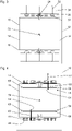
- FIG. 3 a view from above of the first elevator shaft 12 with a total of eight drive machines 34 is shown.
- the drive machines 34 are each drivingly connected to a traction sheave in the form of a deflection roller 30 over which a trotting means 26 runs.
- the reference numbers shown only once In each case four drive machines 34 are arranged on opposite sides of the elevator car 16 , with two drive machines 34 being arranged on different sides of the vertical guide rail 24 on each of the opposite sides of the elevator car 16 .
- Drive axles 52 of the drive machines 34 run parallel to one another, with a drive machine 34 being arranged on one side of the elevator car 16 coaxially to a drive machine 34 on the other side of the elevator car 16 .
- a car door, not shown, of the elevator car 16 is located on one or both free sides 54 of the elevator car 16, on which no drive machines 34 are arranged.
- the elevator control 36 controls two drive machines 34 on opposite sides in the same way or synchronously, so that the suspension elements 26 assigned to them also move or are displaced synchronously.
- Two drive machines 34 are controlled in the same way, which are arranged diagonally with respect to a center of gravity 56 of the elevator car, for example in 3 the upper, far left drive machine 34 and the lower, far right drive machine 34. With the eight drive machines 34, a total of four elevator cars 14, 16 can be displaced in the first elevator shaft 12 simultaneously and independently of one another.
- each coupling device 58 has a bolt 60 which can be extended and retracted in an actuation direction 62 which is oriented in the direction of the coupling elements 44 .
- the coupling device 58 has an actuating actuator 64, which can be embodied as an electric motor, for example.
- the bolt 60 can be moved together with the actuating actuator 64 horizontally and perpendicularly to the actuating direction 62 along a rail 66 by means of a positioning actuator 68, which is also designed as an electric motor, for example.
- the bolt 60 is first correctly positioned with respect to the corresponding coupling element 44 . Then the bolt 60 is extended, whereby the bolt 60 dips into the recess 48 of the coupling element 44 .
- a form-fitting connection is thus produced between the coupling device 58 and the coupling element 44 and thus between the elevator car 16 and the suspension element 26 .
- the elevator car 16 is displaced in the elevator shaft 12 as soon as the suspension element 26 is driven or displaced by the drive machine 34 .
- the elevator car 16 is coupled to two support means 26 which are arranged diagonally with respect to the center of gravity 56 of the elevator car. This takes place in that the elevator car 16 is coupled to coupling elements 44 which are arranged diagonally with respect to the center of gravity 56 of the elevator car 16 .
- Each coupling element 44 is guided by a guide 53 during displacement in the elevator shaft 12 .
- the guide 53 is arranged between each coupling element 44 and the elevator car 16 and runs through the entire elevator shaft 12.
- the Guides 53 prevent, in particular, a free coupling element 44, i.e. a coupling element 44 to which no elevator car 14, 16 is coupled, from striking a passing elevator car 14, 16.
- the bolts of the coupling devices cannot be displaced transversely to the direction of actuation.
- the coupling devices have separate bolts and actuating actuators for each coupling element.
- an elevator car it is also possible for an elevator car to have only one coupling device, so that an elevator car is coupled to only one suspension means for displacement in the elevator shaft. This is the case in particular when the drive machines and thus the suspension means are arranged on a side of the elevator car which is opposite the car door and thus the shaft doors.
- the elevator system 10 In addition to a first elevator shaft 12, it has a second elevator shaft 13, which is arranged parallel to the first elevator shaft 12.
- the second elevator shaft 13 is designed analogously to the first elevator shaft 12 .
- the relocation of the elevator cars 14, 16 in the second elevator shaft 13 is implemented analogously to the relocation in the first elevator shaft 12. In the first elevator shaft 12, the elevator cars 14, 16 are only displaced upwards and in the second elevator shaft 13 only downwards.
- FIG 5a is the first elevator car 14 in the first elevator shaft 12 at the lower end position 18. She is on her in the Figures 5a, 5b and 5c not shown coupling device to a first in which Figure 5a right coupling element 44 of the suspension element 26 is coupled.
- the first elevator car 14 has only one single, non-displaceable coupling device.
- the coupling device is arranged in such a way that it can be coupled to the right-hand coupling element 44 .
- the first elevator car 14 can thus only be coupled to the right-hand coupling element 44, so that the first elevator car 14 is assigned the right-hand coupling element 44.
- a second, in the Figure 5a The left-hand coupling element 44 of the suspension element 26 is arranged on the suspension element 26 in such a way that a coupling device of an elevator car located in the upper end position 22 could be uncoupled from the second coupling element 44 .
- a deflection roller 28, 30 is arranged in each case.
- the drive machine 34 drives the upper deflection roller 30 in a counterclockwise direction of movement, which is indicated by a directional arrow 69 .
- the first elevator car 14 is shifted between the lower end position 18 and the upper end position 22 to the upper end position 22 with possible intermediate stops at floors.
- the second is in the Figure 5a Left coupling element 44 shifted down.
- neither of the two coupling elements 44 comes into contact with one of the two deflection rollers 28, 30.
- the coupling elements 44 therefore neither touch one of the two deflection rollers 28, 30, nor are they guided around the deflection rollers 28, 30.
- the second elevator car 16 is located in the Figure 5a in the second elevator shaft 13 at the upper end position 22. She is in the Figures 5a, 5b and 5c not shown coupling device to a first in which Figure 5a left coupling element 44 of the suspension element 26 is coupled.
- the second elevator car 16 also has only a single, non-displaceable coupling device.
- the coupling device is arranged in such a way that it can be coupled to the left-hand coupling element 44 .
- the second elevator car 16 can thus only be coupled to the left-hand coupling element 44 , so that the left-hand coupling element 44 is assigned to the second elevator car 16 .
- a second, in the Figure 5a The right-hand coupling element 44 of the suspension element 26 is arranged on the suspension element 26 in such a way that a coupling device of an elevator car located in the lower end position 18 is uncoupled from the second coupling element 44 could.
- a deflection roller 28, 30 is arranged in each case.
- the drive machine 34 To move the second elevator car 16 downwards, the drive machine 34 also drives the upper deflection roller 30 counterclockwise.
- the second elevator car 16 is shifted between the upper end position 22 and the lower end position 18 to the lower end position 18 with possible intermediate stops at floors.
- the second Simultaneously with the shift of the first, in the Figure 5a left coupling element 44 down, the second is in the Figure 5a right coupling element 44 shifted upwards. During said displacement, neither of the two coupling elements 44 comes into contact with one of the two deflection rollers 28, 30.
- the elevator system 10 has a first, upper transfer device 70 by means of which the first elevator car 14 can be shifted from the first elevator shaft 12 into the second elevator shaft 13 at the upper end position 22 .
- the first transfer device 70 has a vertical guide rail piece 72 which guides the first elevator car 14 in the first transfer device 70 .
- the first transfer device 70 is positioned such that the guide rail piece 72 forms a section of the vertical guide rail 24 of the first elevator shaft 12, by which the first elevator car 14 is guided during displacement in the first elevator shaft 12.
- the first elevator car 14 has a braking device 74 with which the first elevator car 14 is temporarily fixed to the guide rail piece 72 integrated in the first transfer device 70 during the displacement between the first elevator shaft 12 and the second elevator shaft 13 .
- the elevator system 10 also has a second, lower transfer device 76 for moving the second elevator car 16 in the lower end position 18 from the second elevator shaft 13 into the first elevator shaft 12.
- the second, lower transfer device 76 is designed analogously to the first, upper transfer device 70.
- the second elevator car 16 also has a braking device 74.
- the transfer devices 70, 76 can in particular corresponding to the transfer devices in the form of horizontal displacement units EP 2219985 B1 be executed.
- FIG 5c the situation after the displacement of the two elevator cars 14, 16 is shown.
- the first elevator car 14 is positioned in the second elevator shaft 13 at the upper end position 22 and the second elevator car 16 is positioned in the first elevator shaft 12 at the lower end position 18 .
- the drive machine 34 To move the second elevator car 16 upwards, the drive machine 34 now drives the upper deflection roller 30 in a clockwise direction.
- the drive machine 34 is thus controlled by the elevator control in such a way that the direction of movement of the suspension element 26 is reversed for the next displacement of an elevator car when an elevator car has reached the lower end position or the upper end position.
- the second elevator car 16 is shifted between the lower end position 18 and the upper end position 22 to the upper end position 22 with possible intermediate stops at floors. Simultaneously with the shift of the second, in the Figure 5c left coupling element 44 upwards, the first is in the Figure 5c right coupling element 44 shifted downwards.
- the first elevator car 14 is located in the Figure 5c in the second elevator shaft 13 the upper end position 22. She is on her coupling device to the second, in which Figure 5c right coupling element 44 of the suspension element 26 is coupled.
- the first in the Figure 5c The left-hand coupling element 44 of the suspension element 26 is arranged on the suspension element 26 in such a way that a coupling device of an elevator car located in the lower end position 18 could be uncoupled from the second coupling element 44 .
- the drive machine 34 In order to move the first elevator car 14 downwards, the drive machine 34 now also drives the upper deflection roller 30 in a clockwise direction. It takes place compared to Figure 5a ie a reversal of the direction of movement of the suspension element 26 also takes place.
- the first elevator car 14 is shifted between the upper end position 22 and the lower end position 18 to the lower end position 18 with possible intermediate stops at floors. Simultaneously with the shift of the second, in the Figure 5c right coupling element 44 down, the first is in the Figure 5c left coupling element 44 shifted upwards.
- the elevator system it is also possible for the elevator system to have a third elevator shaft in which elevator cars that are currently not required can be parked.
Description
Die Erfindung betrifft ein Aufzugsystem mit den Merkmalen des Oberbegriffs des Anspruchs 1.The invention relates to an elevator system having the features of the preamble of
Die
Die Aufzugkabinen werden in dem genannten Aufzugschacht nur in eine Richtung, also nur nach oben oder nur nach unten verlagert. Um einen umlaufenden Betrieb der Aufzugkabinen realisieren zu können, verfügt das Aufzugsystem über einen weiteren Aufzugschacht. Die Aufzugkabinen können zwischen den beiden Aufzugschächten mittels einer Transfereinrichtung horizontal verschoben werden. Im Betrieb des Aufzugsystems koppelt sich eine Aufzugkabine an einer unteren bzw. einer oberen Endposition über ihre Kopplungseinrichtung und ein Ankoppelelement an ein Tragmittel an und wird über das Tragmittel von der zugehörigen Antriebsmaschine nach oben bzw. unten verlagert, bis sie die obere bzw. untere Endposition erreicht hat. Dort koppelt sich die Aufzugkabine vom Tragmittel ab und wird von einer Transfereinrichtung in den Aufzugschacht für die andere Verlagerungsrichtung horizontal in den anderen Aufzugschachtverschoben.The elevator cars are only moved in one direction in the named elevator shaft, ie only upwards or only downwards. In order to be able to operate the elevator cabins in a circulating manner, the elevator system has an additional elevator shaft. The elevator cars can be moved horizontally between the two elevator shafts by means of a transfer device. During operation of the elevator system, an elevator car is coupled to a suspension element at a lower or an upper end position via its coupling device and a coupling element and is displaced upwards or downwards by the associated drive machine via the suspension element until it reaches the upper or lower end position has reached. There the elevator car is uncoupled from the suspension element and is horizontally shifted by a transfer device into the elevator shaft for the other direction of displacement into the other elevator shaft.
Demgegenüber ist es insbesondere die Aufgabe der Erfindung, ein Aufzugsystem vorzuschlagen, welches einen komfortablen Betrieb ermöglicht, insbesondere ohne besondere Anforderungen an die Ausgestaltung der Ankoppelelemente des Tragmittel zu stellen. Erfindungsgemäss wird diese Aufgabe mit einem Aufzugsystem mit den Merkmalen des Anspruchs 1 gelöst.In contrast, it is in particular the object of the invention to propose an elevator system which enables comfortable operation, in particular without to make special demands on the design of the coupling elements of the support means. According to the invention, this object is achieved with an elevator system having the features of
Das erfindungsgemässe Aufzugsystem verfügt über eine erste Aufzugkabine und eine zweite Aufzugkabine, die in einem ersten Aufzugschacht in vertikaler Richtung verlagerbar sind. Es weist zusätzlich ein in sich geschlossenes, um eine untere Umlenkrolle und eine obere Umlenkrolle geführtes Tragmittel, eine dem Tragmittel zugeordnete Antriebsmaschine, eine an der ersten Aufzugkabine angeordnete ansteuerbare Kopplungseinrichtung und eine an der zweiten Aufzugkabine angeordnete ansteuerbare Kopplungseinrichtung auf. Das Tragmittel verfügt über ein erstes und ein zweites Ankoppelelement, an welche sich eine Kopplungseinrichtung einer Aufzugkabine ankoppeln und abkoppeln kann, womit eine Antriebsverbindung zwischen der jeweiligen Aufzugkabine und dem Tragmittel herstellbar und lösbar ist. Eine angekoppelte Aufzugkabine kann damit mittels des von der jeweiligen Antriebsmaschine antreibbaren Tragmittels im ersten Aufzugschacht verlagert werden. Erfindungsgemäss sind die beiden Ankoppelelemente des Tragmittels so angeordnet, dass bei einer Verlagerung der über ein Ankoppelelement an das Tragmittel angekoppelten ersten Aufzugkabine von einer unteren Endposition zu einer oberen Endposition oder umgekehrt, kein Ankoppelelement des Tragmittels um eine Umlenkrolle herumgeführt wird.The elevator system according to the invention has a first elevator car and a second elevator car, which can be displaced in the vertical direction in a first elevator shaft. It also has a self-contained suspension element guided around a lower deflection roller and an upper deflection roller, a drive machine assigned to the suspension element, a controllable coupling device arranged on the first elevator car and a controllable coupling device arranged on the second elevator car. The suspension element has a first and a second coupling element to which a coupling device of an elevator car can be coupled and uncoupled, with which a drive connection between the respective elevator car and the suspension element can be established and released. A coupled elevator car can thus be displaced in the first elevator shaft by means of the suspension element that can be driven by the respective drive machine. According to the invention, the two coupling elements of the suspension element are arranged in such a way that when the first elevator car, which is coupled to the suspension element via a coupling element, is displaced from a lower end position to an upper end position or vice versa, no coupling element of the suspension element is guided around a deflection roller.
Damit wird bei der genannten Verlagerung der Aufzugkabine zwischen den beiden Endpositionen, also bei einer maximalen Verlagerung im Aufzugschacht, kein Ankoppelelement um bzw. über eine der Umlenkrollen geführt. Es wird somit lediglich das flexible Tragmittel über die Umlenkrollen geführt, was ohne Komforteinbussen, wie beispielsweise Ruckeln oder Geräuschentwicklung, möglich ist. Ausserdem muss bei der Ausgestaltung der Ankoppelelemente weder darauf geachtet werden, dass sie überhaupt um bzw. über die Umlenkrollen geführt werden können, noch ob sie mit möglichst geringen Komforteinbussen um bzw. über die Umlenkrollen geführt werden können. Die Ankoppelelemente können so optimal auf ihre Aufgabe, die Ankopplung der Kopplungseinrichtung en an ein Tragmittel zu ermöglichen, ausgelegt werden. Darüber hinaus muss im Bereich der Umlenkrollen kein Bauraum vorgesehen werden, in dem die Ankoppelelemente um die Umlenkrollen herumgeführt werden können. Das ermöglicht eine einfachere Konstruktion des Aufzugsystems.This means that no coupling element is guided around or over one of the deflection rollers when the elevator car is displaced between the two end positions, that is to say when there is a maximum displacement in the elevator shaft. Thus, only the flexible suspension element is guided over the deflection rollers, which is possible without sacrificing comfort, such as jerking or noise development. In addition, when designing the coupling elements, it is not necessary to ensure that they can be guided around or over the deflection rollers at all, nor whether they can be guided around or over the deflection rollers with as little loss of comfort as possible. The coupling elements can thus be optimally designed for their task of enabling the coupling devices to be coupled to a suspension element. In addition, no installation space has to be provided in the area of the deflection rollers in which the coupling elements can be guided around the deflection rollers. This enables a simpler construction of the elevator system.
Die erfindungsgemässe Anordnung der Ankoppelelemente an einem Tragmittel erlaubt es, die dem Tragmittel zugeordnete Antriebsmaschine so anzusteuern, dass im Betrieb des Aufzugsystems nie ein Ankoppelelement um eine Umlenkrolle herumgeführt wird.The arrangement according to the invention of the coupling elements on a suspension means allows the drive machine assigned to the suspension means to be controlled in such a way that a coupling element is never guided around a deflection pulley during operation of the elevator system.
Der Aufzugschacht ist in oder an einem Gebäude angeordnet und verläuft hauptsächlich in vertikaler Richtung, so dass die Aufzugkabinen bei einer Verlagerung im Aufzugschacht hauptsächlich vertikal verlagert werden. Die genannte erste und zweite Aufzugkabine müssen nicht gleichzeitig im ersten Aufzugschacht verlagerbar sein. Es ist insbesondere möglich, dass zuerst die erste Aufzugkabine im Aufzugschacht verlagert wird und anschliessend die zweite Aufzugkabine insbesondere in die selbe Richtung im Aufzugschacht verlagert wird. Die erste Aufzugkabine wird dazu insbesondere vor oder während der Verlagerung der zweiten Aufzugkabine aus dem Aufzugschacht entfernt.The elevator shaft is arranged in or on a building and runs mainly in the vertical direction, so that when the elevator cars are moved in the elevator shaft, they are mainly moved vertically. Said first and second elevator cars do not have to be displaceable in the first elevator shaft at the same time. In particular, it is possible for the first elevator car to be displaced in the elevator shaft first and then the second elevator car to be displaced in the elevator shaft, in particular in the same direction. For this purpose, the first elevator car is removed from the elevator shaft, in particular before or during the displacement of the second elevator car.
Das Tragmittel ist in sich geschlossen, also beispielsweise ringförmig ausgeführt. Es kann damit auch als endlos bezeichnet werden. Das bedeutet aber nicht zwingend, dass es als ein homogener Ring oder nur aus einem Stück besteht. Das Tragmittel ist um eine untere und eine obere Umlenkrolle geführt, wobei mindestens eine Umlenkrolle als Antriebsrolle oder Treibscheibe dient, über die das Tragmittel von der ihm zugeordneten Antriebsmaschine angetrieben werden kann. Die Umlenkrollen weisen insbesondere einen Wirkdurchmesser von weniger als 100 mm auf. Derart geringe Wirkdurchmesser einer als Treibscheibe dienenden Umlenkrolle ermöglichen einen getriebelosen Antrieb des Tragmittels, der wenig Einbauraum beansprucht. Die Umlenkrollen sind insbesondere so angeordnet, dass ihre jeweilige Rotationsachse senkrecht zu einer benachbarten Schachtwand des Aufzugschachts ist. Am Tragmittel kann insbesondere eine Spannvorrichtung angeordnet sein, mit welcher einerseits die erforderliche Tragmittelvorspannung erzeugt und andererseits Abweichungen in der ursprünglichen Länge des in sich geschlossenen Tragmittels sowie betriebsbedingte plastische Längenänderungen des Tragmittels ausgeglichen werden. Die erforderlichen Spannkräfte lassen sich beispielsweise mit Spanngewichten, Gasfedern oder Metallfedern erzeugen.The support means is self-contained, that is to say, for example, is designed in the shape of a ring. It can thus also be described as endless. However, this does not necessarily mean that it consists of a homogeneous ring or just one piece. The suspension element is guided around a lower and an upper deflection roller, with at least one deflection roller serving as a drive roller or traction sheave, via which the suspension element can be driven by the drive machine assigned to it. In particular, the deflection rollers have an effective diameter of less than 100 mm. Such small effective diameters of a deflection pulley serving as a traction sheave enable a gearless drive of the suspension element, which requires little installation space. The deflection rollers are in particular arranged in such a way that their respective axis of rotation is perpendicular to an adjacent shaft wall of the elevator shaft. In particular, a tensioning device can be arranged on the suspension element, with which on the one hand the required suspension element pretension is generated and on the other hand deviations in the original length of the self-contained suspension element and operational plastic length changes of the suspension element are compensated for. The required tensioning forces can be generated, for example, with tensioning weights, gas springs or metal springs.
Die Antriebsmaschine ist insbesondere als ein Elektromotor ausgeführt, der von einer Aufzugsteuerung angesteuert wird. Die Aufzugsteuerung steuert den kompletten Betrieb des Aufzugsystems, sie steuert also alle ansteuerbaren Komponenten des Aufzugsystems an und ist mit Schaltern und Sensoren des Aufzugsystems verbunden. Die Aufzugsteuerung kann als eine einzige zentrale Aufzugsteuerung ausgeführt sein oder aus mehreren dezentralen Steuerung bestehen, die für Teilaufgaben zuständig sind.The drive machine is designed in particular as an electric motor that is controlled by an elevator controller. The elevator controller controls the entire operation of the elevator system, ie it controls all controllable components of the elevator system and is connected to switches and sensors of the elevator system. The elevator control can be designed as a single central elevator control or consist of several decentralized controls that are responsible for subtasks.
Die an den Aufzugkabinen angeordneten Kopplungseinrichtungen sind insbesondere an einem Boden oder einem Dach der Aufzugkabinen angeordnet und werden von der oben genannten Aufzugsteuerung angesteuert. Die Ankopplung an ein Ankoppelelement des Tragmittels erfolgt insbesondere formschlüssig, wobei auch eine reibschlüssige Ankopplung denkbar ist. Das Ankoppelelement verfügt insbesondere über eine hauptsächlich horizontal orientierte Ausnehmung, in die beispielsweise in eine Betätigungsrichtung ein aus- und einfahrbarer Bolzen der Ankoppeleinrichtung eintauchen kann. Über die Kopplungseinrichtung und das Ankoppelelement kann damit eine form- oder reibschlüssige Verbindung zwischen der Aufzugkabine und dem Tragmittel hergestellt werden, so dass bei einer Verlagerung bzw. Bewegung des Treibmittels auch die Aufzugkabine verlagert wird. Damit ist eine Antriebsverbindung zwischen der Aufzugkabine und dem Tragmittel und damit letztlich zwischen der Aufzugkabine und der dem Tragmittel zugeordneten Antriebsmaschine herstellbar und auch wieder lösbar. Die Kopplungseinrichtungen werden so angesteuert, dass zumindest während der Verlagerung einer Aufzugkabine an ein (einziges) Tragmittel nur eine Aufzugkabine angekoppelt ist. Von einem (einzigen) Tragmittel wird damit immer nur eine (einzige) Aufzugkabine im Schacht verlagert.The coupling devices arranged on the elevator cars are arranged in particular on a floor or a roof of the elevator cars and are controlled by the elevator control mentioned above. The coupling to a coupling element of the suspension element takes place in particular in a form-fitting manner, with a friction-fitting coupling also being conceivable. The coupling element has, in particular, a mainly horizontally oriented recess into which, for example, an extendable and retractable bolt of the coupling device can enter in an actuation direction. A positive or frictional connection between the elevator car and the suspension element can thus be produced via the coupling device and the coupling element, so that the elevator car is also displaced when the propellant is displaced or moved. A drive connection between the elevator car and the suspension element, and thus ultimately between the elevator car and the drive machine assigned to the suspension element, can thus be established and also released again. The coupling devices are controlled in such a way that, at least during the displacement of an elevator car, only one elevator car is coupled to a (single) suspension element. Only one (single) elevator car is shifted in the shaft by a (single) suspension element.
In Ausgestaltung der Erfindung sind die beiden Ankoppelelemente des Tragmittels so angeordnet, dass bei einer Verlagerung der über ein Ankoppelelement an das Tragmittel angekoppelten ersten Aufzugkabine von einer unteren Endposition zu einer oberen Endposition oder umgekehrt, kein Ankoppelelement in Kontakt zu einer Umlenkrolle kommt. Darunter ist zu verstehen, dass das Ankoppelelement die Umlenkrollen nicht berührt. Es kann damit zu keinen Beschädigungen einer Umlenkrolle durch ein Ankoppelelement oder umgekehrt kommen.In an embodiment of the invention, the two coupling elements of the suspension element are arranged in such a way that when the first elevator car, which is coupled to the suspension element via a coupling element, is displaced from a lower end position to an upper end position or vice versa, no coupling element comes into contact with a deflection roller. This means that the coupling element does not touch the deflection rollers. A deflection roller cannot be damaged by a coupling element or vice versa.
Diese Anordnung der Ankoppelelemente an einem Tragmittel erlaubt es, die dem Tragmittel zugeordnete Antriebsmaschine so anzusteuern, dass im Betrieb des Aufzugsystems nie ein Ankoppelelement in Kontakt mit einer Umlenkrolle kommt. Das Tragmittel kann also immer so rechtzeitig angehalten werden, dass die Ankoppelelemente die Umlenkrollen nie erreichen oder beispielsweise einen bestimmten Mindestabstand zu den Umlenkrollen einhalten.This arrangement of the coupling elements on a suspension means allows the drive machine assigned to the suspension means to be controlled in such a way that a coupling element never comes into contact with a deflection pulley during operation of the elevator system. The support means can therefore always be stopped in good time for the coupling elements never reach the deflection rollers or, for example, maintain a certain minimum distance from the deflection rollers.
In Ausgestaltung der Erfindung sind die beiden Ankoppelelemente des Tragmittels so angeordnet, dass wenn die über ein Ankoppelelement an das Tragmittel angekoppelte erste Aufzugkabine bei einer Verlagerung nach oben die obere Endposition erreicht hat, das andere Ankoppelelement so positioniert ist, dass sich die der zweiten Aufzugkabine zugeordnete Kopplungseinrichtung der in der unteren Endposition angeordneten zweiten Aufzugkabine an das andere Ankoppelelement ankoppeln kann. Bei einer Verlagerung der ersten Aufzugkabine nach unten ist das andere Ankoppelelement dementsprechend bei Erreichen der unteren Endposition der ersten Aufzugkabine so positioniert, dass sich die Kopplungseinrichtung der in der oberen Endposition angeordneten zweite Aufzugkabine an das andere Ankoppelelement ankoppeln kann. Damit kann sich immer dann, wenn die erste Aufzugkabine eine der beiden Endpositionen erreicht hat, die zweite Aufzugkabine an der anderen Endposition an ein Ankoppelelement ankoppeln und damit die Verlagerung der zweiten Aufzugkabine vorbereiten. Damit kann das Abkoppeln der ersten Aufzugkabine und das Ankoppeln der zweiten Aufzugkabine zumindest teilweise gleichzeitig ablaufen, womit ein effektiver Betrieb des Aufzugsystems ermöglicht wird.In an embodiment of the invention, the two coupling elements of the suspension element are arranged in such a way that when the first elevator car, which is coupled to the suspension element via a coupling element, has reached the upper end position during an upward displacement, the other coupling element is positioned in such a way that the one assigned to the second elevator car moves Coupling device arranged in the lower end position of the second elevator car can couple to the other coupling element. When the first elevator car is moved downwards, the other coupling element is accordingly positioned when the first elevator car reaches the lower end position such that the coupling device of the second elevator car arranged in the upper end position can couple to the other coupling element. This means that whenever the first elevator car has reached one of the two end positions, the second elevator car can be coupled to a coupling element at the other end position and thus prepare for the displacement of the second elevator car. In this way, the uncoupling of the first elevator car and the coupling of the second elevator car can take place at least partially simultaneously, with the result that an effective operation of the elevator system is made possible.
In Ausgestaltung der Erfindung wird die Antriebsmaschine von einer Aufzugsteuerung angesteuert. Diese ist dazu vorgesehen, eine Bewegungsrichtung des Tragmittels für die nächste Verlagerung einer Aufzugkabine umzukehren, wenn eine Aufzugkabine je nach Verlagerungsrichtung die untere Endposition oder die obere Endposition erreicht hat. Damit ist es vorteilhaft möglich, beide Aufzugkabinen des Aufzugsystems in der gleichen Richtung im Aufzugschacht zu verlagern, ohne dass im Betrieb der Aufzuganlage ein Ankoppelelement um eine Umlenkrolle herumgeführt wird oder mit einer Umlenkrolle in Kontakt kommt. Die Aufzugsteuerung ist damit dazu vorgesehen, die Aufzugkabinen im Aufzugschacht nur in einer Richtung, also nur von unten nach oben oder nur von oben nach unten zu verlagern.In an embodiment of the invention, the drive machine is controlled by an elevator controller. This is intended to reverse a direction of movement of the suspension element for the next displacement of an elevator car when an elevator car has reached the lower end position or the upper end position, depending on the direction of displacement. It is thus advantageously possible to move both elevator cars of the elevator system in the same direction in the elevator shaft without a coupling element being guided around a deflection roller or coming into contact with a deflection roller during operation of the elevator system. The elevator control is thus intended to move the elevator cars in the elevator shaft only in one direction, ie only from bottom to top or only from top to bottom.
In Ausgestaltung der Erfindung weist das Aufzugsystem wenigstens ein weiteres Tragmittel mit zwei in vertikaler Richtung voneinander beabstandet angeordneten Ankoppelelementen und ein weiteres dem weiteren Tragmittel zugeordnete Antriebsmaschine auf. Die Ankoppelelemente sind wie bei dem bereits beschriebenen Tragmittel angeordnet. Die Tragmittel sind insbesondere parallel nebeneinander im Aufzugschacht angeordnet. Die Aufzugsteuerung ist insbesondere dazu vorgesehen, die beiden Antriebsmaschinen der Tragmittel unabhängig voneinander anzusteuern. Damit kann mit einem zweiten Tragmittel gleichzeitig mit der ersten Aufzugkabine und unabhängig von der ersten Aufzugkabine eine weitere Aufzugkabine im Aufzugschacht verlagert werden. Damit kann das Aufzugsystem besonders effektiv betrieben werden und es können viele Passagiere insbesondere mit unterschiedlichen Zielstockwerken im Gebäude transportiert werden. Das Aufzugsystem weist insbesondere mehr als zwei, im Speziellen vier derartige Tragmittel auf. Es ist auch denkbar, dass das Aufzugsystem mehr als vier derartige Tragmittel aufweist.In an embodiment of the invention, the elevator system has at least one additional suspension element with two coupling elements arranged spaced apart from one another in the vertical direction and another drive machine assigned to the additional suspension element. The coupling elements are like those already described Carrying means arranged. In particular, the support means are arranged parallel next to one another in the elevator shaft. The elevator control is provided in particular to control the two drive machines of the suspension elements independently of one another. A further elevator car can thus be shifted in the elevator shaft with a second suspension element at the same time as the first elevator car and independently of the first elevator car. The elevator system can thus be operated particularly effectively and many passengers can be transported in the building, in particular with different destination floors. In particular, the elevator system has more than two, in particular four, such suspension elements. It is also conceivable that the elevator system has more than four such suspension elements.
Wenn mehr als ein Tragmittel vorhanden ist, kann es notwendig sein, dass sich die Kopplungseinrichtungen an die Ankoppelelemente der verschiedenen Tragmittel ankoppeln können. Die Kopplungseinrichtungen sind dann horizontal insbesondere quer zu ihrer Betätigungsrichtung verschiebbar angeordnet. Wenn eine Aufzugkabine an ein Tragmittel angekoppelt werden soll, so wird zuerst die Kopplungseinrichtung so quer zu ihrer Betätigungsrichtung verschoben, dass sie korrekt gegenüber dem Ankoppelelement des entsprechenden Tragmittels positioniert ist. Anschliessend kann insbesondere durch Ausfahren des Bolzens des Ankoppelelements die Ankopplung an das Tragmittel erfolgen. Es ist für diesen Fall auch möglich, dass pro Tragmittel eine entsprechend positionierte Kopplungseinrichtung an der Aufzugkabine vorgesehen ist.If there is more than one suspension element, it may be necessary for the coupling devices to be able to couple to the coupling elements of the various suspension elements. The coupling devices are then arranged to be displaceable horizontally, in particular transversely to their direction of actuation. When an elevator car is to be coupled to a suspension element, the coupling device is first displaced transversely to its direction of actuation in such a way that it is correctly positioned in relation to the coupling element of the corresponding suspension element. The coupling to the suspension element can then take place, in particular by extending the bolt of the coupling element. In this case, it is also possible for a correspondingly positioned coupling device to be provided on the elevator car for each suspension element.
Auch wenn mehrere Tragmittel vorhanden sind, kann eine Kopplungseinrichtung an einer festen Position, also eine nicht verschiebbare Kopplungseinrichtung, pro Aufzugkabine ausreichend sein. Dazu ist eine Zuordnung einer Aufzugkabine zu einem Ankoppelelement notwendig, auf die weiter unten genauer eingegangen wird.Even if there are several suspension elements, one coupling device in a fixed position, that is to say a non-displaceable coupling device, per elevator car can be sufficient. This requires an elevator car to be assigned to a coupling element, which will be discussed in more detail below.
In Ausgestaltung der Erfindung ist ein Ankoppelelement eines jeden Tragmittels als ein Verbindungselement ausgeführt, welches zwei freie Enden von Tragmittelteilen miteinander verbindet. Damit kann das Ankoppelelement vorteilhaft eine Doppelfunktion erfüllen, nämlich zum einen die Ankopplung einer Aufzugkabine und zum anderen ein geschlossenes Tragmittel ermöglichen. Das Ankoppelelement erfüllt insbesondere die Funktion eines so genannten Riemenschlosses oder eines Seilverbinders. Damit kann sehr einfach, kostengünstig und sicher aus einem offenen, langgestreckten Tragmittelteil durch Verbinden der beiden freien Enden mit dem Ankoppelelement ein in sich geschlossenes Tragmittel hergestellt werden. Das Tragmittel besteht damit aus zwei Tragmittelteilen, deren freien Enden mittels eines primären Ankoppelelements und eines sekundären Ankoppelelements verbunden sind. Dabei ist jeweils ein freies Ende des ersten Tragmittelteils mit einem freien Ende des zweiten Tragmittelteils verbunden, so dass das Tragmittel einen geschlossenen Ring bildet. Das Ankoppelelement kann beispielsweise zwei miteinander verbundene Tragmittelendverbindungen aufweisen, welche beispielsweise entsprechend der
Insbesondere sind beide Ankoppelelemente eines jeden Tragmittels als Verbindungselemente ausgeführt. Damit besteht ein Tragmittel des erfindungsgemässen Aufzugsystems aus zwei offenen, langestreckten Tragmittelteilen und zwei als Verbindungselemente ausgeführte Ankoppelelementen, welche jeweils zwei freie Ende unterschiedlicher Tragmittelteile miteinander verbinden. Die Ankoppelelemente sind dabei insbesondere identisch ausgeführt. Dies ermöglicht die Verwendung von möglichst vielen gleichen Teilen, was zum einen geringere Herstellkosten ermöglicht und zum anderen die Montage einfacher macht, da alle Ankoppelelemente gleich montiert werden können bzw. müssen.In particular, both coupling elements of each suspension element are designed as connecting elements. A suspension element of the elevator system according to the invention thus consists of two open, elongated suspension element parts and two coupling elements designed as connecting elements, which each connect two free ends of different suspension element parts to one another. In particular, the coupling elements are designed identically. This enables the use of as many identical parts as possible, which on the one hand enables lower production costs and on the other hand makes assembly easier since all coupling elements can or must be assembled in the same way.
In Ausgestaltung der Erfindung sind die Tragmittel als Riemen ausgeführt. Riemen haben ausgezeichnete Traktionseigenschaften und eignen sich besonders gut zum Zusammenwirken mit ansteuerbaren Kopplungseinrichtungen Die Riemen können beispielsweise als Flachriemen, Keilrippenriemen oder Zahnriemen ausgebildet sein und können mit Zugverstärkungen in Form von Drahtseilen, Kunstfaserseilen oder Kunstfasergeweben verstärkt sein. Damit kann eine an das Tragmittel angekoppelte Aufzugskabine über eine grosse Höhe verlagert werden, ohne dass unzulässige Vertikalschwingungen auftreten.In an embodiment of the invention, the suspension means are designed as belts. Belts have excellent traction properties and are particularly suitable for interacting with controllable coupling devices. The belts can be designed as flat belts, V-ribbed belts or toothed belts and can be reinforced with tensile reinforcements in the form of wire ropes, synthetic fiber ropes or synthetic fiber fabrics. In this way, an elevator car coupled to the suspension element can be shifted over a great height without impermissible vertical oscillations occurring.
Es ist aber auch möglich, dass das Tragmittel aus einem oder mehreren Seilen, insbesondere Drahteilen besteht.However, it is also possible for the suspension means to consist of one or more ropes, in particular wire parts.
In Ausgestaltung der Erfindung werden die Ankoppelelemente bei einer Verlagerung im Aufzugschacht geführt. Die dazu verwendete Führung ist dabei insbesondere so ausgeführt, dass sie ein Anschlagen der Ankoppelelemente an eine vorbeifahrende Aufzugkabine verhindert. Dies ermöglicht einen besonders komfortablen und sicheren Betrieb des Aufzugsystems. Bei einer Verlagerung einer Aufzugkabine im Aufzugschacht kann nicht ganz ausgeschlossen werden, dass das Tragmittel und damit das nicht mit einer Aufzugkabine verbundene Ankoppelelement in Schwingung versetzt wird. Ohne eine Führung des Ankoppelelements würde insbesondere die Gefahr bestehen, dass das Ankoppelelement beim Vorbeifahren an der Aufzugkabine an dieser anschlägt. Ein derartiges Anschlagen würde zum einen zu einem hörbaren Schlag führen und könnte zum anderen Schäden an der Aufzugkabine und/oder dem Ankoppelelement hervorrufen. Diese Gefahr wird durch die Führung der Ankoppelelemente vermieden.In an embodiment of the invention, the coupling elements are guided when shifted in the elevator shaft. The guide used for this is designed in particular in such a way that it prevents the coupling elements from hitting a passing elevator car. This enables a particularly comfortable and safe operation of the elevator system. When an elevator car is relocated in the elevator shaft, it cannot be completely ruled out that the suspension element and thus the coupling element that is not connected to an elevator car will vibrate. Without a guide for the coupling element, there would in particular be a risk that the coupling element would hit the elevator car when driving past it. Such an impact would, on the one hand, lead to an audible impact and, on the other hand, could cause damage to the elevator car and/or the coupling element. This danger is avoided by guiding the coupling elements.
In Ausgestaltung der Erfindung weist jede Aufzugkabine zwei Kopplungseinrichtungen auf. Diese sind dazu vorgesehen, sich gleichzeitig an Ankoppelelemente zweier verschiedener Tragmittel anzukoppeln. Die Antriebsmaschinen der beiden Tragmittel werden synchronisiert angesteuert, so dass beide Tragmittel synchron angetrieben und verlagert werden. Die beiden Kopplungseinrichtungen einer Aufzugkabine sind insbesondere an gegenüberliegenden Seiten der Aufzugkabine angeordnet. Sie sind insbesondere dazu vorgesehen, an diagonal gegenüberliegenden Positionen an jeweils ein Ankoppelelement eines Tragmittels anzukoppeln. Dies ermöglicht eine besonders gleichmässige bzw. gleichmässig verteilte Krafteinleitung in die Aufzugkabine, was ein sehr geringes Verkippen der Aufzugkabine während der Verlagerung ermöglicht. Damit ist zum einen ein komfortables Verfahren der Aufzugkabine möglich und zum anderen werden Führungen der Aufzugkabine wenig belastet, was eine einfache und kostengünstigere Auslegung möglich macht und ausserdem zu einem sehr geringen Verschleiss führt. Zusätzlich muss im Vergleich zu nur einer Kopplungseinrichtung pro Aufzugkabine nur ungefähr die halbe Kraft über eine Kopplungseinrichtung eingeleitet werden. Dies ermöglicht den Einsatz kostengünstiger Antriebsmaschinen, die ausserdem nur einen geringen Bauraum beanspruchen.In an embodiment of the invention, each elevator car has two coupling devices. These are intended to be coupled to the coupling elements of two different suspension means at the same time. The drive machines of the two suspension elements are controlled in a synchronized manner, so that both suspension elements are driven and displaced synchronously. The two coupling devices of an elevator car are arranged in particular on opposite sides of the elevator car. They are intended in particular to be coupled to a respective coupling element of a suspension element at diagonally opposite positions. This enables a particularly even or evenly distributed introduction of force into the elevator car, which allows the elevator car to tilt very little during the displacement. On the one hand, this enables the elevator car to be moved comfortably and, on the other hand, guides in the elevator car are subjected to little stress, which makes a simple and more cost-effective design possible and also leads to very little wear. In addition, compared to only one coupling device per elevator car, only approximately half the force has to be introduced via a coupling device. This enables the use of cost-effective drive machines, which also only take up a small amount of space.
Die beiden Kopplungseinrichtungen sind dazu insbesondere nicht mechanisch gekoppelt, sondern werden von der Aufzugsteuerung entsprechend angesteuert. Die Kopplungseinrichtungen sind beim Ankoppeln an die beiden Tragmittel insbesondere so positioniert, dass eine Verbindungslinie auf Höhe des Schwerpunkts der Aufzugkabine zwischen den beiden Ankoppelelementen der Tragmittel durch den genannten Schwerpunkt verläuft. Dies ermöglicht eine besonders gleichmässige Krafteinleitung in die Aufzugkabine.For this purpose, the two coupling devices are in particular not mechanically coupled, but are controlled accordingly by the elevator control. The coupling devices are particularly like this when they are coupled to the two suspension elements positioned so that a connecting line runs through said center of gravity at the height of the center of gravity of the elevator car between the two coupling elements of the suspension means. This enables a particularly even introduction of force into the elevator car.
Es ist auch möglich, dass jede Aufzugkabine nur eine einzige Kopplungseinrichtung aufweist. Die Aufzugkabine kann sich dann nur an ein Tragmittel ankoppeln und mittels diesem im Aufzugschacht verlagert werden.It is also possible for each elevator car to have only a single coupling device. The elevator car can then only be coupled to one suspension means and be displaced in the elevator shaft by means of this.
In Ausgestaltung der Erfindung sind die erste und die zweite Aufzugkabine auch in einem einen zweiten, parallel zum ersten Aufzugschacht angeordneten Aufzugschacht in vertikaler Richtung verlagerbar. Das Aufzugsystem verfügt ausserdem über eine erste Transfereinrichtung, mittels welcher Aufzugkabinen vom ersten Aufzugschacht in den zweiten Aufzugschacht verschoben werden können, und eine zweite Transfereinrichtung, mittels welcher Aufzugkabinen vom zweiten Aufzugschacht in den ersten Aufzugschacht verschoben werden können. Eine Verlagerung der Aufzugkabinen im zweiten Aufzugschacht ist dabei analog zur Verlagerung im ersten Aufzugschacht realisiert. Die Aufzugkabinen werden insbesondere im ersten Aufzugschacht nur von unten nach oben und im zweiten Aufzugschacht nur von oben nach unten verlagert. Es ist dabei nicht relevant, welcher Aufzugschacht als der erste und welcher als der zweite Aufzugschacht bezeichnet wird.In an embodiment of the invention, the first and the second elevator car can also be displaced in the vertical direction in a second elevator shaft arranged parallel to the first elevator shaft. The elevator system also has a first transfer device, by means of which elevator cars can be moved from the first elevator shaft to the second elevator shaft, and a second transfer device, by means of which elevator cars can be moved from the second elevator shaft to the first elevator shaft. A relocation of the elevator cars in the second elevator shaft is implemented analogously to the relocation in the first elevator shaft. In particular, the elevator cars are shifted only from bottom to top in the first elevator shaft and only from top to bottom in the second elevator shaft. It is not relevant which elevator shaft is designated as the first and which as the second elevator shaft.
Unter einer analogen Realisierung der Verlagerung der Aufzugkabinen im Aufzugschacht soll dabei verstanden werden, dass im zweiten Aufzugschacht ebenfalls mindestens ein Tragmittel mit zwei entsprechend angeordneten Ankoppelelementen vorgesehen ist, das über eine zugeordnete Antriebsmaschine angetrieben werden kann. Daneben sind alle oben genannten Ausgestaltungen der Erfindung auch auf den zweiten Aufzugschacht anwendbar.An analog realization of the shifting of the elevator cars in the elevator shaft is to be understood that at least one suspension element with two correspondingly arranged coupling elements is also provided in the second elevator shaft, which can be driven via an associated drive machine. In addition, all of the above-mentioned configurations of the invention can also be applied to the second elevator shaft.
Das Vorsehen des zweiten Aufzugschachts und der beiden Transfereinrichtungen ermöglichen vorteilhafterweise einen umlaufenden Betrieb des Aufzugsystems. Die Transfereinrichtungen sind insbesondere im Bereich der Endpositionen der Aufzugkabinen angeordnet. Erreicht beispielsweise eine Aufzugkabine bei einer Verlagerung im ersten Aufzugschacht nach oben die obere Endposition, dann wird sie nachdem alle Passagiere die Aufzugkabine verlassen haben und sie sich vom Tragmittel abgekoppelt hat, mittels der oberen Transfereinrichtung in die obere Endposition des zweiten Aufzugschachts horizontal verschoben. Anschliessend kann sie sich an ein Tragmittel im zweiten Aufzugschacht ankoppeln und so im zweiten Aufzugschacht nach unten bis zur unteren Endposition verlagert werden. Von dort wird sie wiederum von der unteren Transfereinrichtung horizontal in die untere Endposition des ersten Aufzugschachts verschoben, von der aus sie wieder nach oben verlagert werden kann. Dabei können insbesondere mehrere, beispielsweise vier Aufzugkabinen pro Aufzugschacht gleichzeitig verlagert werden, wobei an ein Tragmittel immer nur eine Aufzugkabine angekoppelt ist. Damit wird ein besonders effektiver Betrieb des Aufzugsystems ermöglicht.The provision of the second elevator shaft and the two transfer devices advantageously enable circulating operation of the elevator system. The transfer devices are arranged in particular in the area of the end positions of the elevator cars. If, for example, an elevator car reaches the upper end position when moving upwards in the first elevator shaft, then it after all passengers have left the elevator car and it has been uncoupled from the suspension means, is horizontally shifted to the upper end position of the second elevator shaft by means of the upper transfer device. It can then be coupled to a suspension element in the second elevator shaft and thus be shifted downwards in the second elevator shaft to the lower end position. From there it is in turn shifted horizontally by the lower transfer device into the lower end position of the first elevator shaft, from where it can be shifted back up. In this case, in particular, several, for example four, elevator cars per elevator shaft can be shifted simultaneously, with only one elevator car ever being coupled to a suspension element. This enables a particularly effective operation of the elevator system.
Die Transfereinrichtungen können insbesondere entsprechend den Transfereinrichtungen in Form von Horizontalverschiebeeinheiten der
In Ausgestaltung der Erfindung sind im ersten Aufzugschacht und im zweiten Aufzugschacht jeweils eine gleiche Anzahl von Tragmitteln mit jeweils zwei Ankoppelelementen angeordnet. Eine Anzahl der Aufzugkabinen ist maximal gleich gross wie eine Gesamtanzahl der Tragmittel des Aufzugsystems. Die Anzahl der Aufzugkabinen ist insbesondere genau gleich gross wie die Gesamtanzahl der Tragmittel. Das bedeutet, dass die Anzahl der Ankoppelelemente pro Aufzugschacht grösser oder gleich der Anzahl der in einem Aufzugschacht zu verlagernden Aufzugkabinen ist. Damit kann jeder Aufzugkabine in jedem der beiden Aufzugschächte ein bestimmtes Ankoppelelement oder bei der gleichzeitigen Ankopplung an zwei Tragmittel zwei Ankoppelelemente zugeordnet werden, wobei die jeweiligen Ankoppelelemente in den beiden Aufzugschächten an der selben Position angeordnet sind. Unter einer Zuordnung soll in diesem Zusammenhang verstanden werden, dass sich eine Aufzugkabine über ihre Kopplungseinrichtung ausschliesslich an das oder die ihr zugeordneten Ankoppelelemente ankoppelt. Damit benötigt jede Aufzugkabine nur ein oder bei einer gleichzeitigen Ankopplung an zwei Ankoppelelemente nur zwei Kopplungseinrichtungen, die jeweils an einer festen Position angeordnet sind. Die Kopplungseinrichtungen sind damit nicht quer zur Betätigungsrichtung der Bolzens der Kopplungseinrichtungen verschiebbar. Dies ermöglicht eine kostengünstige Realisierung der Kopplungseinrichtungen. Ausserdem benötigen die Kopplungseinrichtung in diesem Fall besonders wenig Bauraum.In an embodiment of the invention, the same number of suspension elements, each with two coupling elements, are arranged in the first elevator shaft and in the second elevator shaft. A maximum number of elevator cars is the same size as a total number of suspension elements of the elevator system. In particular, the number of elevator cars is exactly the same as the total number of suspension elements. This means that the number of coupling elements per elevator shaft is greater than or equal to the number of elevator cars to be shifted in an elevator shaft. In this way, each elevator car in each of the two elevator shafts can be assigned a specific coupling element or, if coupled to two suspension elements at the same time, two coupling elements, with the respective coupling elements being arranged in the same position in the two elevator shafts. Under an assignment is to be understood in this context that an elevator car is coupled via its coupling device exclusively to the coupling element or elements assigned to it. Each elevator car therefore requires only one coupling device or, in the case of simultaneous coupling to two coupling elements, only two coupling devices which are each arranged at a fixed position. The coupling devices are thus not displaceable transversely to the direction of actuation of the bolt of the coupling devices. This enables the coupling devices to be implemented in a cost-effective manner. In addition, in this case the coupling device requires particularly little installation space.
Beispielsweise kann bei zwei Tragmitteln (ein linkes und ein rechtes Tragmittel) und damit vier Ankoppelelementen (ein links und ein rechtes Ankoppelelement pro Tragmittel) pro Aufzugschacht der ersten Aufzugkabine das linke Ankoppelelement des linken Tragmittels, der zweiten Aufzugkabine das linke Ankoppelelement des rechten Tragmittels, der dritten Aufzugkabine das rechte Ankoppelelement des linken Tragmittels und der vierten Aufzugkabine das rechte Ankoppelelement des rechten Tragmittels zugeordnet werden. Diese Zuordnungen sind in beiden Aufzugschächten gleich. Das einer Aufzugkabine zugeordnete Ankoppelelement ist damit in beiden Aufzugschächten an der gleichen Position angeordnet. Damit benötigt beispielsweise die erste Aufzugkabine nur eine Kopplungseinrichtung, welche so positioniert ist, dass sie sich nur an das linke Ankoppelelement des linken Tragmittels ankoppeln kann.For example, with two suspension elements (one left and one right suspension element) and thus four coupling elements (one left and one right coupling element per suspension element) per elevator shaft of the first elevator car, the left coupling element of the left suspension element, of the second elevator car the left coupling element of the right suspension element, the the right-hand coupling element of the left-hand suspension element can be assigned to the third elevator car and the right-hand coupling element of the right-hand suspension element to the fourth elevator car. These assignments are the same in both elevator shafts. The coupling element assigned to an elevator car is thus arranged in the same position in both elevator shafts. Thus, for example, the first elevator car requires only one coupling device, which is positioned in such a way that it can only be coupled to the left-hand coupling element of the left-hand suspension element.
Weitere Vorteile, Merkmale und Einzelheiten der Erfindung ergeben sich anhand der nachfolgenden Beschreibung von Ausführungsbeispielen sowie anhand der Zeichnungen, in welchen gleiche oder funktionsgleiche Elemente mit identischen Bezugszeichen versehen sind. Die Zeichnungen sind lediglich schematisch und nicht massstabsgetreu.Further advantages, features and details of the invention result from the following description of exemplary embodiments and from the drawings, in which elements that are the same or have the same function are provided with identical reference symbols. The drawings are merely schematic and not true to scale.
Dabei zeigen:
- Fig. 1
- einen ersten Aufzugschacht eines Aufzugssystems mit einer ersten und einer zweiten Aufzugkabine,
- Fig. 2
- ein Ankoppelelement eines Tragmittels aus
Fig. 1 in einer vergrösserten Darstellung, - Fig. 3
- eine Sicht von oben auf den ersten Aufzugschacht mit insgesamt acht Antriebmaschinen,
- Fig. 4
- eine Sicht von unten auf eine Aufzugkabine mit zwei Kopplungseinrichtungen zur Ankopplung an Ankoppelelemente der Tragmittel und
- Fig. 5a -c
- eine stark vereinfachte Darstellung eines Aufzugsystems mit zwei Aufzugschächten, zwei Transfereinrichtungen und zwei Aufzugkabinen mit unterschiedlichen Positionen der Aufzugkabinen zur Erläuterung der Funktionsweise des Aufzugsystems.
- 1
- a first elevator shaft of an elevator system with a first and a second elevator car,
- 2
- a coupling element of a
suspension element 1 in an enlarged view, - 3
- a view from above of the first elevator shaft with a total of eight drive machines,
- 4
- a view from below of an elevator car with two coupling devices for coupling to coupling elements of the support means and
- Figures 5a-c
- a highly simplified representation of an elevator system with two elevator shafts, two transfer devices and two elevator cars with different positions of the elevator cars to explain how the elevator system works.
Gemäss
Das Aufzugsystem 10 verfügt über eine in vertikaler Richtung verlaufende Vertikalführungsschiene 24, an der die Aufzugkabinen 14, 16 während einer Verlagerung im Aufzugschacht 12 geführt werden. Zur Verlagerung der Aufzugkabinen 14, 16 im Aufzugschacht 12 verfügt das Aufzugsystem 10 über insgesamt acht in sich geschlossene Tragmittel 26, von denen in der
Die beiden Umlenkrollen 28, 30 eines Tragmittels 26 sind vertikal übereinander angeordnet, so dass die Tragmittel 26 zwischen den Umlenkrollen 28, 30 vertikal verlaufen. Die Umlenkrollen 28, 30 weisen insbesondere einen Wirkdurchmesser von weniger als 100 mm auf. Die unteren Umlenkrollen 28 sind unterhalb der ersten Aufzugkabine 14 angeordnet und jeweils mit einem Spanngewicht 32 verbunden. Das Spanngewicht 32 wirkt als eine Spannvorrichtung, mit welcher einerseits die erforderliche Tragmittelvorspannung erzeugt und andererseits Abweichungen in der ursprünglichen Länge des in sich geschlossenen Tragmittels 26 sowie betriebsbedingte plastische Längenänderungen des Tragmittels 26 ausgeglichen werden.The two
Die oberen Umlenkrollen 30 sind oberhalb der zweiten Aufzugkabine 16 angeordnet und dienen jeweils als Treibscheibe für eine als Elektromotor ausgeführte Antriebsmaschine 34. Jedem Tragmittel 26 ist eine Antriebsmaschine 34 zugeordnet, mittels welcher das Tragmittel 26 angetrieben und verlagert werden kann. Die Antriebsmaschinen 34 werden von einer Aufzugsteuerung 36 angesteuert, welche sämtliche Aktoren des Aufzugsystems 10 ansteuert.The
Jedes Tragmittel 26 besteht aus zwei Tragmittelteilen 38, 40, deren freien Enden 42 (siehe
Es ist auch möglich, dass die Kopplungseinrichtungen am Dach einer Aufzugkabine angeordnet sind. Die Positionen der Ankoppelelemente an den Tragmitteln müssen dann entsprechend angepasst sein.It is also possible for the coupling devices to be arranged on the roof of an elevator car. The positions of the coupling elements on the support means must then be adjusted accordingly.
Sobald eine Aufzugkabine 14, 16 über eine ihr zugeordnete Kopplungseinrichtung 58 an ein Ankoppelelement 44 angekoppelt ist, ist eine Antriebsverbindung zwischen der Aufzugkabine 14, 16 und dem Tragmittel 26 hergestellt. In diesem angekoppelten Zustand wird die Aufzugkabine 14, 16 vom Tragmittel 26 mitgenommen und damit im Aufzugschacht 12 verlagert, wenn das Tragmittel 26 von der ihm zugeordneten Antriebsmaschine 34 angetrieben bzw. verlagert wird. Im in
In
Die Aufzugsteuerung 36 steuert zwei Antriebsmaschinen 34 auf gegenüberliegenden Seiten gleich bzw. synchron an, so dass sich die ihnen zugeordneten Tragmittel 26 ebenfalls synchron bewegen bzw. verlagert werden. Es werden zwei Antriebsmaschinen 34 gleich angesteuert, welche bezüglich eines Schwerpunkts 56 der Aufzugkabine diagonal angeordnet sind, also beispielsweise in
In
Zum Ankoppeln einer Kopplungseinrichtung 58 und damit der Aufzugkabine 16 an ein Ankoppelelement 44 und damit an ein Tragmittel 26 wird zunächst der Bolzen 60 korrekt bezüglich dem entsprechenden Ankoppelelement 44 positioniert. Anschliessend wird der Bolzen 60 ausgefahren, womit der Bolzen 60 in die Ausnehmung 48 des Ankoppelelements 44 eintaucht. Damit wird eine formschlüssige Verbindung zwischen der Kopplungseinrichtung 58 und dem Ankoppelelement 44 und damit zwischen der Aufzugkabine 16 und dem Tragmittel 26 hergestellt. Wenn diese formschlüssige Verbindung hergestellt ist, wird die Aufzugkabine 16 im Aufzugschacht 12 verlagert, sobald das Tragmittel 26 von der Antriebsmaschine 34 angetrieben bzw. verlagert wird.In order to couple a
Wie bereits in Zusammenhang mit
Jedes Ankoppelelement 44 wird bei der Verlagerung im Aufzugschacht 12 von einer Führung 53 geführt. Die Führung 53 ist zwischen jedem Ankoppelelement 44 und der Aufzugkabine 16 angeordnet und verläuft durch den gesamten Aufzugschacht 12. Die Führungen 53 verhindern insbesondere ein Anschlagen eines freien Ankoppelelements 44, also ein Ankoppelelement 44, an das keine Aufzugkabine 14, 16 angekoppelt ist, an eine vorbeifahrende Aufzugkabine 14, 16.Each
Es ist auch möglich, dass die Bolzen der Kopplungseinrichtungen nicht quer zur Betätigungsrichtung verschiebbar sind. In diesem Fall weisen die Kopplungseinrichtungen für jedes Ankoppelelement separate Bolzen und Betätigungsaktoren auf.It is also possible that the bolts of the coupling devices cannot be displaced transversely to the direction of actuation. In this case, the coupling devices have separate bolts and actuating actuators for each coupling element.
Es ist auch möglich, dass eine Aufzugkabine nur eine Kopplungseinrichtung aufweist, so dass sich eine Aufzugkabine zum Verlagern im Aufzugschacht nur an ein Tragmittel ankoppelt. Dies ist insbesondere dann der Fall, wenn die Antriebsmaschinen und damit die Tragmittel an einer der Kabinentür und damit Schachttüren gegenüberliegenden Seite der Aufzugkabinen angeordnet sind.It is also possible for an elevator car to have only one coupling device, so that an elevator car is coupled to only one suspension means for displacement in the elevator shaft. This is the case in particular when the drive machines and thus the suspension means are arranged on a side of the elevator car which is opposite the car door and thus the shaft doors.
Mit den Darstellungen der
Das Aufzugsystem 10 gemäss
In der
Ein zweites, in der
Zum Verlagern der ersten Aufzugkabine 14 nach oben, treibt die Antriebsmaschine 34 die obere Umlenkrolle 30 in einer Bewegungsrichtung gegen den Uhrzeigersinn an, was mit einem Richtungspfeil 69 angezeigt wird. Die erste Aufzugkabine 14 wird mit eventuellen Zwischenstopps an Stockwerken zwischen der unteren Endposition 18 und der oberen Endposition 22 bis zur oberen Endposition 22 verlagert. Gleichzeitig mit der Verlagerung des ersten, in der
Die zweite Aufzugkabine 16 befindet sich in der
Ein zweites, in der
Zum Verlagern der zweiten Aufzugkabine 16 nach unten, treibt die Antriebsmaschine 34 die obere Umlenkrolle 30 ebenfalls gegen den Uhrzeigersinn an. Die zweite Aufzugkabine 16 wird mit eventuellen Zwischenstopps an Stockwerken zwischen der oberen Endposition 22 und der unteren Endposition 18 bis zur unteren Endposition 18 verlagert. Gleichzeitig mit der Verlagerung des ersten, in der
In
Zur Durchführung von Schachtwechseln weist das Aufzugsystem 10 eine erste, obere Transfereinrichtung 70 auf, mittels welcher die erste Aufzugkabine 14 an der oberen Endposition 22 vom ersten Aufzugschacht 12 in den zweiten Aufzugschacht 13 verschoben werden kann. Die erste Transfereinrichtung 70 weist ein vertikales Führungsschienenstück 72 auf, das die erste Aufzugkabine 14 in der ersten Transfereinrichtung 70 führt. Die erste Transfereinrichtung 70 ist vor Beginn der Verschiebung so positioniert, dass das Führungsschienenstück 72 einen Abschnitt der Vertikalführungsschiene 24 des ersten Aufzugschachts 12 bildet, von der die erste Aufzugkabine 14 während einer Verlagerung im ersten Aufzugschacht 12 geführt wird. Die erste Aufzugskabine 14 weist eine Bremseinrichtung 74 auf, mit welcher die erste Aufzugkabine 14 an dem in der ersten Transfereinrichtung 70 integrierten Führungsschienenstück 72 während der Verschiebung zwischen dem ersten Aufzugschacht 12 und dem zweiten Aufzugschacht 13 temporär fixiert ist.In order to carry out shaft changes, the
Das Aufzugsystem 10 verfügt ausserdem über eine zweite, untere Transfereinrichtung 76 zum Verschieben der zweiten Aufzugkabine 16 in der untere Endposition 18 vom zweiten Aufzugschacht 13 in den ersten Aufzugschacht 12. Die zweite, untere Transfereinrichtung 76 ist analog zur ersten, oberen Transfereinrichtung 70 ausgeführt. Die zweite Aufzugkabine 16 verfügt ebenfalls über eine Bremseinrichtung 74.The
Die Transfereinrichtungen 70, 76 können insbesondere entsprechend den Transfereinrichtungen in Form von Horizontalverschiebeeinheiten der
In
Die jetzt im ersten Aufzugschacht 12 an der unteren Endposition 18 angeordnete zweite Aufzugkabine 16 ist jetzt über ihre Kopplungseinrichtung an das zweite, in der
Zum Verlagern der zweiten Aufzugkabine 16 nach oben, treibt die Antriebsmaschine 34 die obere Umlenkrolle 30 jetzt im Uhrzeigersinn an. Die Antriebsmaschine 34 wird also von der Aufzugsteuerung so angesteuert, dass die Bewegungsrichtung des Tragmittels 26 für die nächste Verlagerung einer Aufzugkabine umgekehrt wird, wenn eine Aufzugkabine die untere Endposition oder die obere Endposition erreicht hat.To move the
Die zweite Aufzugkabine 16 wird mit eventuellen Zwischenstopps an Stockwerken zwischen der unteren Endposition 18 und der oberen Endposition 22 bis zur oberen Endposition 22 verlagert. Gleichzeitig mit der Verlagerung des zweiten, in der
Die erste Aufzugkabine 14 befindet sich in der
Zum Verlagern der ersten Aufzugkabine 14 nach unten, treibt die Antriebsmaschine 34 die obere Umlenkrolle 30 jetzt ebenfalls im Uhrzeigersinn an. Es findet im Vergleich zu
Nach diesem in
Es ist auch möglich, dass das Aufzugsystem einen dritten Aufzugschacht aufweist, in dem aktuell nicht benötigte Aufzugkabinen geparkt werden können.It is also possible for the elevator system to have a third elevator shaft in which elevator cars that are currently not required can be parked.
Abschließend ist darauf hinzuweisen, dass Begriffe wie "aufweisend", "umfassend", etc. keine anderen Elemente oder Schritte ausschließen und Begriffe wie "eine" oder "ein" keine Vielzahl ausschließen. Ferner sei daraufhingewiesen, dass Merkmale oder Schritte, die mit Verweis auf eines der obigen Ausführungsbeispiele beschrieben worden sind, auch in Kombination mit anderen Merkmalen oder Schritten anderer oben beschriebener Ausführungsbeispiele verwendet werden können. Bezugszeichen in den Ansprüchen sind nicht als Einschränkung anzusehen.Finally, it should be noted that terms such as "comprising," "comprising," etc. do not exclude other elements or steps, and terms such as "a" or "an" do not exclude a plurality. Furthermore, it should be pointed out that features or steps that have been described with reference to one of the above exemplary embodiments can also be used in combination with other features or steps of other exemplary embodiments described above. Any reference signs in the claims should not be construed as limiting.
Claims (15)
- Elevator system, comprising- a first elevator car (14) and a second elevator car (16) which can be moved in a first elevator shaft (12) in the vertical direction,- a closed support means (26) which is guided about a lower deflection roller (28) and an upper deflection roller (30),- a drive machine (34) which is assigned to the support means (26), and- an actuatable coupling device (58) arranged on the first elevator car (14) and an actuatable coupling device (58) arranged on the second elevator car (16),the support means (26) having a first and a second coupling element (44), to and from which a coupling device (58) can be coupled and decoupled, as a result of which a drive connection can be established and detached between the relevant elevator car (14, 16) and the support means (26), and a coupled elevator car (14, 16) can be moved in the first elevator shaft (12) by means of the support means (26) drivable by the relevant drive machine (34),
characterized in that
the two coupling elements (44) of the support means (26) are arranged such that in a movement of the first elevator car (14), which is coupled to the support means (26) via a coupling element (44), from a lower end position (18) to an upper end position (22), or vice versa, no coupling element (44) is guided about a deflection roller (28, 30). - Elevator system according to claim 1,
characterized in that
the two coupling elements (44) of the support means (26) are arranged such that in a movement of the first elevator car (14), which is coupled to the support means (26) via a coupling element (44), from a lower end position (18) to an upper end position (22), or vice versa, no coupling element (44) comes into contact with a deflection roller (28, 30). - Elevator system according to claim 1 or 2,
characterized in that
the two coupling elements (44) of the support means (26) are arranged such that, when the first elevator car (14), which is coupled to the support means (26) via a coupling element (44), has reached the upper end position (22), the other coupling element (44) is positioned such that the coupling device (58), assigned to the second elevator car (16), of the second elevator car (16) arranged in the lower end position (18) can be coupled to the other coupling element (44). - Elevator system according to claims 1, 2 or 3,
characterized in that
the drive machine (34) is actuated by an elevator controller (36) which is provided to reverse a movement direction (69) of the support means (26) for the next movement of an elevator car (14, 16) when an elevator car (14, 16) has reached the lower end position (18) or the upper end position (22). - Elevator system according to any of claims 1 to 4,
characterized by
a further support means (26) comprising two coupling elements (44) spaced apart from one another in the vertical direction and a further drive machine (34) assigned to the further support means (26). - Elevator system according to any of claims 1 to 5,
characterized in that
a coupling element (44) of each support means (26) is designed as a connecting element which interconnects two free ends (42) of support means parts (38, 40). - Elevator system according to claim 6,
characterized in that
the two coupling elements (44) of each support means (26) are designed as connecting elements. - Elevator system according to any of claims 1 to 7,
characterized in that
the support means (26) are designed as belts. - Elevator system according to any of claims 1 to 8,
characterized in that
during a movement, the coupling elements (44) are guided in the first elevator shaft (12). - Elevator system according to any of claims 1 to 9,
characterized in that
each elevator car (14, 16) comprises two coupling means (58) which are provided to simultaneously couple to coupling elements (44) of two different support means (26). - Elevator system according to claim 10,
characterized in that
the two coupling devices (58) are arranged on opposite sides of the elevator car (14, 16). - Elevator system according to claim 11,
characterized in that
the two coupling devices (58) are provided to be coupled at diagonally opposite positions to one coupling element (44) of a support means (26) in each case. - Elevator system according to any of claims 1 to 12,
characterized in thatthe first elevator car (14) and the second elevator car (16) can also be moved in the vertical direction in a second elevator shaft (13) arranged in parallel with the first elevator shaft (12), andthe elevator system (10) comprises- a first transfer device (70), by means of which elevator cars (14, 16) can be displaced from the first elevator shaft (12) to the second elevator shaft (13), and- a second transfer device (76), by means of which elevator cars (14, 16) can be displaced from the second elevator shaft (13) to the first elevator shaft (12),a movement of the elevator cars (14, 16) in the second elevator shaft (13) being realized analogously to the movement in the first elevator shaft (12). - Elevator system according to claim 13,
characterized in that
the elevator cars (14, 16) in the first elevator shaft (12) are moved only from the bottom to the top, and in the second elevator shaft (13) are moved only from the top to the bottom. - Elevator system according to claim 13 or 14,
characterized in that
an equal number of support means (26), each having two coupling elements (44), are arranged in the first elevator shaft (12) and in the second elevator shaft (13), and a number of the elevator cars (14, 16) is at most equal to a total number of the support means (26).
Applications Claiming Priority (2)
| Application Number | Priority Date | Filing Date | Title |
|---|---|---|---|
| EP17186585 | 2017-08-17 | ||
| PCT/EP2018/070656 WO2019034405A1 (en) | 2017-08-17 | 2018-07-31 | Elevator system |
Publications (2)
| Publication Number | Publication Date |
|---|---|
| EP3668810A1 EP3668810A1 (en) | 2020-06-24 |
| EP3668810B1 true EP3668810B1 (en) | 2022-06-22 |
Family
ID=59649573
Family Applications (2)
| Application Number | Title | Priority Date | Filing Date |
|---|---|---|---|
| EP18745596.9A Active EP3681835B1 (en) | 2017-08-17 | 2018-07-25 | Elevator system |
| EP18743833.8A Active EP3668810B1 (en) | 2017-08-17 | 2018-07-31 | Elevator system |
Family Applications Before (1)
| Application Number | Title | Priority Date | Filing Date |
|---|---|---|---|
| EP18745596.9A Active EP3681835B1 (en) | 2017-08-17 | 2018-07-25 | Elevator system |
Country Status (6)
| Country | Link |
|---|---|
| US (2) | US11623845B2 (en) |
| EP (2) | EP3681835B1 (en) |
| CN (2) | CN110997543B (en) |
| AU (2) | AU2018317641B2 (en) |
| SG (2) | SG11202000750VA (en) |
| WO (2) | WO2019034381A1 (en) |
Families Citing this family (5)
| Publication number | Priority date | Publication date | Assignee | Title |
|---|---|---|---|---|
| US11623845B2 (en) * | 2017-08-17 | 2023-04-11 | Inventio Ag | Elevator system |
| US20220089407A1 (en) * | 2019-02-12 | 2022-03-24 | Inventio Ag | Elevator system |
| US11737431B2 (en) * | 2020-05-29 | 2023-08-29 | Denise Michelle Berger | Bird feeder support system |
| US11665974B2 (en) * | 2021-01-27 | 2023-05-30 | International Business Machines Corporation | MRAM containing magnetic top contact |
| EP4180379A1 (en) * | 2021-11-12 | 2023-05-17 | Norvento Tecnología, S.L.U. | System and method for vertically moving weights |
Family Cites Families (40)
| Publication number | Priority date | Publication date | Assignee | Title |
|---|---|---|---|---|
| US3910383A (en) * | 1974-04-22 | 1975-10-07 | Vladimir Friedl | Manlift |
| DE2542262A1 (en) | 1975-09-23 | 1977-03-24 | Ernst Schmid | Escalator for combined upward and downward travel - has foward and return stages in same plane with individual steps used in both stages |
| JP2665686B2 (en) * | 1989-12-05 | 1997-10-22 | 眸 島田 | Vertical transportation |
| JP3182320B2 (en) | 1995-07-17 | 2001-07-03 | 株式会社日立製作所 | Retractable circulation type elevator |
| JPH09194159A (en) | 1996-01-17 | 1997-07-29 | Mitsubishi Denki Bill Techno Service Kk | Rope hole covering device |
| JPH1059659A (en) | 1996-08-22 | 1998-03-03 | Tetsuzo Shibuya | Elevator |
| JP2000086121A (en) | 1998-09-09 | 2000-03-28 | Ohbayashi Corp | Elevator device |
| EP1367018B1 (en) * | 2002-05-27 | 2010-10-06 | Inventio AG | Elevator system with a plurality of self-moving cabins and at least three parallel shafts |
| DE10300992A1 (en) * | 2003-01-14 | 2004-07-22 | Aufzugswerke M. Schmitt & Sohn Gmbh & Co. | Elevator with separate car suspension |
| JP2005132527A (en) * | 2003-10-29 | 2005-05-26 | Hitachi Ltd | Multi-car elevator |
| JP2005200162A (en) | 2004-01-15 | 2005-07-28 | Toshiba Elevator Co Ltd | Speed governing device for elevator |
| JP4301105B2 (en) | 2004-07-26 | 2009-07-22 | 株式会社日立製作所 | Elevator equipment |
| ZA200506660B (en) | 2004-09-13 | 2006-05-31 | Inventio Ag | Belt end connection for fastening a belt end in a lift installation and method for protecting and checking a belt end connection in a lift installation |
| JP4543868B2 (en) * | 2004-10-15 | 2010-09-15 | 株式会社日立製作所 | Multi car elevator |
| EP1693331A1 (en) | 2005-02-17 | 2006-08-23 | Inventio Ag | Elevator system with several shafts and with elevator cars that can be coupled and uncoupled from the selected drive system. |
| JP4552793B2 (en) | 2005-07-22 | 2010-09-29 | 株式会社日立製作所 | Multi-car elevator safety system |
| MY149179A (en) * | 2006-12-14 | 2013-07-31 | Inventio Ag | Lift system |
| US7661513B2 (en) | 2006-12-14 | 2010-02-16 | Inventio Ag | Dual-car elevator system with common counterweight |
| US7857103B2 (en) * | 2006-12-14 | 2010-12-28 | Inventio Ag | Elevator system |
| EP2070860A1 (en) * | 2007-12-11 | 2009-06-17 | Inventio Ag | Lift system with vertically and horizontally moveable lift cabins |
| EP2072445A1 (en) * | 2007-12-21 | 2009-06-24 | Inventio Ag | Operational method for a lift with two lift cabins and a common counterweight |
| WO2010072656A1 (en) | 2008-12-26 | 2010-07-01 | Inventio Ag | A plurality of elevator cars in an elevator shaft with improved shaft utilization |
| US9132991B2 (en) * | 2009-12-15 | 2015-09-15 | Inventio Ag | Elevator system having a double-decker |
| FR2958635B1 (en) * | 2010-04-12 | 2012-08-31 | Fernand Voillot | MONTE-CHARGE AND BUILDING EQUIPE OF A MONTE-CHARGE. |
| DE102010030436A1 (en) * | 2010-06-23 | 2011-12-29 | Thyssenkrupp Elevator Ag | elevator system |
| US8430210B2 (en) * | 2011-01-19 | 2013-04-30 | Smart Lifts, Llc | System having multiple cabs in an elevator shaft |
| JP2012246116A (en) | 2011-05-30 | 2012-12-13 | Mitsubishi Electric Corp | Elevator device, and emergency stop test method thereof |
| FI124330B (en) * | 2012-01-02 | 2014-06-30 | Kone Corp | Elevator Arrangement and Method for Redesigning the Elevator Arrangement |
| CN104837759B (en) | 2012-12-10 | 2016-11-02 | 因温特奥股份公司 | There is the double-deck elevator of the inter-car distance that can adjust |
| WO2015013684A2 (en) * | 2013-07-26 | 2015-01-29 | Smart Lifts, Llc | System having a plurality of elevator cabs and counterweights that move independently in different sections of a hoistway |
| DE102013110778A1 (en) * | 2013-09-30 | 2015-04-02 | Thyssenkrupp Elevator Ag | elevator system |
| DE102013110791A1 (en) * | 2013-09-30 | 2015-04-02 | Thyssenkrupp Elevator Ag | elevator system |
| DE102013110792A1 (en) * | 2013-09-30 | 2015-04-02 | Thyssenkrupp Elevator Ag | elevator system |
| DE102013110790A1 (en) | 2013-09-30 | 2015-04-02 | Thyssenkrupp Elevator Ag | elevator system |
| US9758347B2 (en) * | 2014-12-02 | 2017-09-12 | ThyssenKrupp Elevator AG; ThyssenKrupp AG | Arrangement and method to move at least two elevator cars independently in at least one hoistway |
| WO2016087706A1 (en) * | 2014-12-05 | 2016-06-09 | Kone Corporation | Elevator arrangement with multiple cars in the same shaft |
| WO2017093595A1 (en) * | 2015-11-30 | 2017-06-08 | Kone Corporation | Adjustable multicar elevator system |
| DE102017113571A1 (en) * | 2017-06-20 | 2018-12-20 | Thyssenkrupp Ag | elevator system |
| US11623845B2 (en) * | 2017-08-17 | 2023-04-11 | Inventio Ag | Elevator system |
| US20220089407A1 (en) * | 2019-02-12 | 2022-03-24 | Inventio Ag | Elevator system |
-
2018
- 2018-07-25 US US16/634,198 patent/US11623845B2/en active Active
- 2018-07-25 AU AU2018317641A patent/AU2018317641B2/en active Active
- 2018-07-25 EP EP18745596.9A patent/EP3681835B1/en active Active
- 2018-07-25 WO PCT/EP2018/070099 patent/WO2019034381A1/en active Search and Examination
- 2018-07-25 SG SG11202000750VA patent/SG11202000750VA/en unknown
- 2018-07-25 CN CN201880053332.2A patent/CN110997543B/en active Active
- 2018-07-31 SG SG11202000756UA patent/SG11202000756UA/en unknown
- 2018-07-31 CN CN201880053333.7A patent/CN110997544B/en active Active
- 2018-07-31 WO PCT/EP2018/070656 patent/WO2019034405A1/en unknown
- 2018-07-31 US US16/634,902 patent/US11535493B2/en active Active
- 2018-07-31 EP EP18743833.8A patent/EP3668810B1/en active Active
- 2018-07-31 AU AU2018319105A patent/AU2018319105B2/en active Active
Also Published As
| Publication number | Publication date |
|---|---|
| AU2018317641A1 (en) | 2020-03-05 |
| US11535493B2 (en) | 2022-12-27 |
| SG11202000750VA (en) | 2020-02-27 |
| CN110997543A (en) | 2020-04-10 |
| CN110997544A (en) | 2020-04-10 |
| SG11202000756UA (en) | 2020-02-27 |
| EP3668810A1 (en) | 2020-06-24 |
| AU2018317641B2 (en) | 2021-09-30 |
| US11623845B2 (en) | 2023-04-11 |
| AU2018319105B2 (en) | 2021-09-30 |
| EP3681835B1 (en) | 2022-08-31 |
| CN110997543B (en) | 2022-04-15 |
| US20200180911A1 (en) | 2020-06-11 |
| AU2018319105A1 (en) | 2020-03-05 |
| CN110997544B (en) | 2021-06-01 |
| US20200231410A1 (en) | 2020-07-23 |
| EP3681835A1 (en) | 2020-07-22 |
| WO2019034381A1 (en) | 2019-02-21 |
| WO2019034405A1 (en) | 2019-02-21 |
Similar Documents
| Publication | Publication Date | Title |
|---|---|---|
| EP3668810B1 (en) | Elevator system | |
| EP3122680B1 (en) | Elevator system | |
| EP1580156B1 (en) | Elevator comprising V-belt-like transmission means, particularly comprising ribbed V-belts, as carrying and/or traction means | |
| EP2219985B1 (en) | Lift system with lift cars which can move vertically and horizontally | |
| EP2398729B1 (en) | Elevator system having a multi-deck vehicle | |
| EP2082983B1 (en) | Lift assembly | |
| EP3807205B1 (en) | Method for operating a lift facility | |
| EP2928805B1 (en) | Double-decker elevator with adjustable inter-cabin distance | |
| EP1935829A1 (en) | Elevator comprising two elevator cars in a shaft | |
| DE10024973B4 (en) | Lifting system for the vertical transport of payloads in an aircraft | |
| EP2512968B1 (en) | Lift facility with double decker | |
| EP3227216B1 (en) | Elevator system | |
| EP3931141B1 (en) | Elevator system | |
| EP3924284B1 (en) | Elevator system | |
| EP3114067B1 (en) | Drive with multiple linking element for an elevator system | |
| AT515346A2 (en) | elevator system | |
| EP3924285B1 (en) | Elevator system | |
| DE10200874A1 (en) | Lift for people and or freight has cage driven by drive unit with drive wheel, power transmission unit, chain with links and shaft | |
| EP3621909B1 (en) | Elevator system with two shafts | |
| EP2468674A1 (en) | Lift facility with double decker | |
| DE19962542B4 (en) | Platform for receiving a motor vehicle | |
| EP3705443A1 (en) | Lift system with balanced traction means | |
| EP1671917A1 (en) | Elevator system with shaftdoor and locking device | |
| WO2023011771A1 (en) | Lift system without a machine room | |
| EP3124424A1 (en) | Load bearing element suspension device with rocking device comprising deflector rollers for a lift system |
Legal Events
| Date | Code | Title | Description |
|---|---|---|---|
| STAA | Information on the status of an ep patent application or granted ep patent |
Free format text: STATUS: UNKNOWN |
|
| STAA | Information on the status of an ep patent application or granted ep patent |
Free format text: STATUS: THE INTERNATIONAL PUBLICATION HAS BEEN MADE |
|
| PUAI | Public reference made under article 153(3) epc to a published international application that has entered the european phase |
Free format text: ORIGINAL CODE: 0009012 |
|
| STAA | Information on the status of an ep patent application or granted ep patent |
Free format text: STATUS: REQUEST FOR EXAMINATION WAS MADE |
|
| 17P | Request for examination filed |
Effective date: 20200115 |
|
| AK | Designated contracting states |
Kind code of ref document: A1 Designated state(s): AL AT BE BG CH CY CZ DE DK EE ES FI FR GB GR HR HU IE IS IT LI LT LU LV MC MK MT NL NO PL PT RO RS SE SI SK SM TR |
|
| AX | Request for extension of the european patent |
Extension state: BA ME |
|
| DAV | Request for validation of the european patent (deleted) | ||
| DAX | Request for extension of the european patent (deleted) | ||
| GRAP | Despatch of communication of intention to grant a patent |
Free format text: ORIGINAL CODE: EPIDOSNIGR1 |
|
| STAA | Information on the status of an ep patent application or granted ep patent |
Free format text: STATUS: GRANT OF PATENT IS INTENDED |
|
| INTG | Intention to grant announced |
Effective date: 20220316 |
|
| GRAS | Grant fee paid |
Free format text: ORIGINAL CODE: EPIDOSNIGR3 |
|
| GRAA | (expected) grant |
Free format text: ORIGINAL CODE: 0009210 |
|
| STAA | Information on the status of an ep patent application or granted ep patent |
Free format text: STATUS: THE PATENT HAS BEEN GRANTED |
|
| AK | Designated contracting states |
Kind code of ref document: B1 Designated state(s): AL AT BE BG CH CY CZ DE DK EE ES FI FR GB GR HR HU IE IS IT LI LT LU LV MC MK MT NL NO PL PT RO RS SE SI SK SM TR |
|
| REG | Reference to a national code |
Ref country code: GB Ref legal event code: FG4D Free format text: NOT ENGLISH |
|
| REG | Reference to a national code |
Ref country code: CH Ref legal event code: EP |
|
| REG | Reference to a national code |
Ref country code: DE Ref legal event code: R096 Ref document number: 502018009987 Country of ref document: DE |
|
| REG | Reference to a national code |
Ref country code: AT Ref legal event code: REF Ref document number: 1499673 Country of ref document: AT Kind code of ref document: T Effective date: 20220715 |
|
| REG | Reference to a national code |
Ref country code: IE Ref legal event code: FG4D Free format text: LANGUAGE OF EP DOCUMENT: GERMAN |
|
| RAP4 | Party data changed (patent owner data changed or rights of a patent transferred) |
Owner name: INVENTIO AG |
|
| REG | Reference to a national code |
Ref country code: LT Ref legal event code: MG9D |
|
| REG | Reference to a national code |
Ref country code: NL Ref legal event code: MP Effective date: 20220622 |
|
| PG25 | Lapsed in a contracting state [announced via postgrant information from national office to epo] |
Ref country code: SE Free format text: LAPSE BECAUSE OF FAILURE TO SUBMIT A TRANSLATION OF THE DESCRIPTION OR TO PAY THE FEE WITHIN THE PRESCRIBED TIME-LIMIT Effective date: 20220622 Ref country code: NO Free format text: LAPSE BECAUSE OF FAILURE TO SUBMIT A TRANSLATION OF THE DESCRIPTION OR TO PAY THE FEE WITHIN THE PRESCRIBED TIME-LIMIT Effective date: 20220922 Ref country code: LT Free format text: LAPSE BECAUSE OF FAILURE TO SUBMIT A TRANSLATION OF THE DESCRIPTION OR TO PAY THE FEE WITHIN THE PRESCRIBED TIME-LIMIT Effective date: 20220622 Ref country code: HR Free format text: LAPSE BECAUSE OF FAILURE TO SUBMIT A TRANSLATION OF THE DESCRIPTION OR TO PAY THE FEE WITHIN THE PRESCRIBED TIME-LIMIT Effective date: 20220622 Ref country code: GR Free format text: LAPSE BECAUSE OF FAILURE TO SUBMIT A TRANSLATION OF THE DESCRIPTION OR TO PAY THE FEE WITHIN THE PRESCRIBED TIME-LIMIT Effective date: 20220923 Ref country code: FI Free format text: LAPSE BECAUSE OF FAILURE TO SUBMIT A TRANSLATION OF THE DESCRIPTION OR TO PAY THE FEE WITHIN THE PRESCRIBED TIME-LIMIT Effective date: 20220622 Ref country code: BG Free format text: LAPSE BECAUSE OF FAILURE TO SUBMIT A TRANSLATION OF THE DESCRIPTION OR TO PAY THE FEE WITHIN THE PRESCRIBED TIME-LIMIT Effective date: 20220922 |
|
| PG25 | Lapsed in a contracting state [announced via postgrant information from national office to epo] |
Ref country code: RS Free format text: LAPSE BECAUSE OF FAILURE TO SUBMIT A TRANSLATION OF THE DESCRIPTION OR TO PAY THE FEE WITHIN THE PRESCRIBED TIME-LIMIT Effective date: 20220622 Ref country code: LV Free format text: LAPSE BECAUSE OF FAILURE TO SUBMIT A TRANSLATION OF THE DESCRIPTION OR TO PAY THE FEE WITHIN THE PRESCRIBED TIME-LIMIT Effective date: 20220622 |
|
| PG25 | Lapsed in a contracting state [announced via postgrant information from national office to epo] |
Ref country code: NL Free format text: LAPSE BECAUSE OF FAILURE TO SUBMIT A TRANSLATION OF THE DESCRIPTION OR TO PAY THE FEE WITHIN THE PRESCRIBED TIME-LIMIT Effective date: 20220622 |
|
| PG25 | Lapsed in a contracting state [announced via postgrant information from national office to epo] |
Ref country code: SM Free format text: LAPSE BECAUSE OF FAILURE TO SUBMIT A TRANSLATION OF THE DESCRIPTION OR TO PAY THE FEE WITHIN THE PRESCRIBED TIME-LIMIT Effective date: 20220622 Ref country code: SK Free format text: LAPSE BECAUSE OF FAILURE TO SUBMIT A TRANSLATION OF THE DESCRIPTION OR TO PAY THE FEE WITHIN THE PRESCRIBED TIME-LIMIT Effective date: 20220622 Ref country code: RO Free format text: LAPSE BECAUSE OF FAILURE TO SUBMIT A TRANSLATION OF THE DESCRIPTION OR TO PAY THE FEE WITHIN THE PRESCRIBED TIME-LIMIT Effective date: 20220622 Ref country code: PT Free format text: LAPSE BECAUSE OF FAILURE TO SUBMIT A TRANSLATION OF THE DESCRIPTION OR TO PAY THE FEE WITHIN THE PRESCRIBED TIME-LIMIT Effective date: 20221024 Ref country code: ES Free format text: LAPSE BECAUSE OF FAILURE TO SUBMIT A TRANSLATION OF THE DESCRIPTION OR TO PAY THE FEE WITHIN THE PRESCRIBED TIME-LIMIT Effective date: 20220622 Ref country code: EE Free format text: LAPSE BECAUSE OF FAILURE TO SUBMIT A TRANSLATION OF THE DESCRIPTION OR TO PAY THE FEE WITHIN THE PRESCRIBED TIME-LIMIT Effective date: 20220622 Ref country code: CZ Free format text: LAPSE BECAUSE OF FAILURE TO SUBMIT A TRANSLATION OF THE DESCRIPTION OR TO PAY THE FEE WITHIN THE PRESCRIBED TIME-LIMIT Effective date: 20220622 |
|
| PG25 | Lapsed in a contracting state [announced via postgrant information from national office to epo] |
Ref country code: PL Free format text: LAPSE BECAUSE OF FAILURE TO SUBMIT A TRANSLATION OF THE DESCRIPTION OR TO PAY THE FEE WITHIN THE PRESCRIBED TIME-LIMIT Effective date: 20220622 Ref country code: IS Free format text: LAPSE BECAUSE OF FAILURE TO SUBMIT A TRANSLATION OF THE DESCRIPTION OR TO PAY THE FEE WITHIN THE PRESCRIBED TIME-LIMIT Effective date: 20221022 |
|
| REG | Reference to a national code |
Ref country code: DE Ref legal event code: R097 Ref document number: 502018009987 Country of ref document: DE |
|
| REG | Reference to a national code |
Ref country code: BE Ref legal event code: MM Effective date: 20220731 |
|
| PG25 | Lapsed in a contracting state [announced via postgrant information from national office to epo] |
Ref country code: MC Free format text: LAPSE BECAUSE OF FAILURE TO SUBMIT A TRANSLATION OF THE DESCRIPTION OR TO PAY THE FEE WITHIN THE PRESCRIBED TIME-LIMIT Effective date: 20220622 Ref country code: AL Free format text: LAPSE BECAUSE OF FAILURE TO SUBMIT A TRANSLATION OF THE DESCRIPTION OR TO PAY THE FEE WITHIN THE PRESCRIBED TIME-LIMIT Effective date: 20220622 |
|
| PG25 | Lapsed in a contracting state [announced via postgrant information from national office to epo] |
Ref country code: LU Free format text: LAPSE BECAUSE OF NON-PAYMENT OF DUE FEES Effective date: 20220731 Ref country code: DK Free format text: LAPSE BECAUSE OF FAILURE TO SUBMIT A TRANSLATION OF THE DESCRIPTION OR TO PAY THE FEE WITHIN THE PRESCRIBED TIME-LIMIT Effective date: 20220622 |
|
| PLBE | No opposition filed within time limit |
Free format text: ORIGINAL CODE: 0009261 |
|
| STAA | Information on the status of an ep patent application or granted ep patent |
Free format text: STATUS: NO OPPOSITION FILED WITHIN TIME LIMIT |
|
| 26N | No opposition filed |
Effective date: 20230323 |
|
| PG25 | Lapsed in a contracting state [announced via postgrant information from national office to epo] |
Ref country code: BE Free format text: LAPSE BECAUSE OF NON-PAYMENT OF DUE FEES Effective date: 20220731 |
|
| PG25 | Lapsed in a contracting state [announced via postgrant information from national office to epo] |
Ref country code: IE Free format text: LAPSE BECAUSE OF NON-PAYMENT OF DUE FEES Effective date: 20220731 |
|
| PG25 | Lapsed in a contracting state [announced via postgrant information from national office to epo] |
Ref country code: SI Free format text: LAPSE BECAUSE OF FAILURE TO SUBMIT A TRANSLATION OF THE DESCRIPTION OR TO PAY THE FEE WITHIN THE PRESCRIBED TIME-LIMIT Effective date: 20220622 |
|
| PGFP | Annual fee paid to national office [announced via postgrant information from national office to epo] |
Ref country code: GB Payment date: 20230725 Year of fee payment: 6 Ref country code: CH Payment date: 20230801 Year of fee payment: 6 |
|
| PGFP | Annual fee paid to national office [announced via postgrant information from national office to epo] |
Ref country code: FR Payment date: 20230725 Year of fee payment: 6 Ref country code: DE Payment date: 20230731 Year of fee payment: 6 |
|
| PG25 | Lapsed in a contracting state [announced via postgrant information from national office to epo] |
Ref country code: IT Free format text: LAPSE BECAUSE OF FAILURE TO SUBMIT A TRANSLATION OF THE DESCRIPTION OR TO PAY THE FEE WITHIN THE PRESCRIBED TIME-LIMIT Effective date: 20220622 |