EP3924285B1 - Elevator system - Google Patents
Elevator system Download PDFInfo
- Publication number
- EP3924285B1 EP3924285B1 EP20702645.1A EP20702645A EP3924285B1 EP 3924285 B1 EP3924285 B1 EP 3924285B1 EP 20702645 A EP20702645 A EP 20702645A EP 3924285 B1 EP3924285 B1 EP 3924285B1
- Authority
- EP
- European Patent Office
- Prior art keywords
- elevator
- runner
- guide
- coupling element
- shaft
- Prior art date
- Legal status (The legal status is an assumption and is not a legal conclusion. Google has not performed a legal analysis and makes no representation as to the accuracy of the status listed.)
- Active
Links
- 230000008878 coupling Effects 0.000 claims description 163
- 238000010168 coupling process Methods 0.000 claims description 163
- 238000005859 coupling reaction Methods 0.000 claims description 163
- 239000000725 suspension Substances 0.000 claims description 66
- 238000006073 displacement reaction Methods 0.000 description 7
- 230000005484 gravity Effects 0.000 description 3
- 230000009977 dual effect Effects 0.000 description 2
- 238000009434 installation Methods 0.000 description 1
- 239000002184 metal Substances 0.000 description 1
- 239000003380 propellant Substances 0.000 description 1
- 239000007787 solid Substances 0.000 description 1
Images


Classifications
-
- B—PERFORMING OPERATIONS; TRANSPORTING
- B66—HOISTING; LIFTING; HAULING
- B66B—ELEVATORS; ESCALATORS OR MOVING WALKWAYS
- B66B9/00—Kinds or types of lifts in, or associated with, buildings or other structures
-
- B—PERFORMING OPERATIONS; TRANSPORTING
- B66—HOISTING; LIFTING; HAULING
- B66B—ELEVATORS; ESCALATORS OR MOVING WALKWAYS
- B66B11/00—Main component parts of lifts in, or associated with, buildings or other structures
- B66B11/0065—Roping
- B66B11/008—Roping with hoisting rope or cable operated by frictional engagement with a winding drum or sheave
- B66B11/0095—Roping with hoisting rope or cable operated by frictional engagement with a winding drum or sheave where multiple cars drive in the same hoist way
-
- B—PERFORMING OPERATIONS; TRANSPORTING
- B66—HOISTING; LIFTING; HAULING
- B66B—ELEVATORS; ESCALATORS OR MOVING WALKWAYS
- B66B7/00—Other common features of elevators
- B66B7/02—Guideways; Guides
- B66B7/04—Riding means, e.g. Shoes, Rollers, between car and guiding means, e.g. rails, ropes
- B66B7/046—Rollers
-
- B—PERFORMING OPERATIONS; TRANSPORTING
- B66—HOISTING; LIFTING; HAULING
- B66B—ELEVATORS; ESCALATORS OR MOVING WALKWAYS
- B66B7/00—Other common features of elevators
- B66B7/06—Arrangements of ropes or cables
- B66B7/08—Arrangements of ropes or cables for connection to the cars or cages, e.g. couplings
- B66B7/085—Belt termination devices
Definitions
- the invention relates to an elevator system having the features of the preamble of claim 1.
- the EP 2219985 B1 describes an elevator system with two elevator cars that can be displaced in a vertical direction in an elevator shaft, a self-contained suspension element guided around a lower deflection roller and an upper deflection roller, a drive machine in the form of an electric motor assigned to the suspension element, and a controllable coupling device arranged on each elevator car.
- the support means has several coupling elements, which can be designed as holes or cams, for example.
- a coupling device of an elevator car can be coupled to and uncoupled from a coupling element, with which a drive connection between the respective elevator car and the suspension element can be established and released.
- An elevator car coupled to a suspension element can thus be displaced in the first elevator shaft by means of the suspension element that can be driven by the respective drive machine.
- the elevator cars are only moved in one direction in the named elevator shaft, ie only upwards or only downwards.
- the elevator system has an additional elevator shaft.
- the elevator cars can be moved horizontally between the two elevator shafts by means of a transfer device.
- an elevator car is coupled to a suspension element at a lower or an upper end position via its coupling device and a coupling element and is displaced upwards or downwards by the associated drive machine via the suspension element until it reaches the upper or lower end position has reached.
- There the elevator car is uncoupled from the suspension element and is horizontally shifted by a transfer device into the elevator shaft for the other direction of displacement into the other elevator shaft.
- the described coupling elements of the suspension means can be connected to an elevator car via a coupling device.
- This Coupling elements are referred to below as connected coupling elements.
- the coupling elements can also not be coupled to an elevator car. These coupling elements are referred to below as free coupling elements.
- both connected and free coupling elements are shifted in the elevator shaft.
- vibrations in the suspension elements can occur.
- the connected coupling elements are prevented from swinging by their coupling to an elevator car. Without suitable countermeasures, the free coupling elements would follow the vibrations of the suspension element. This could result in a free coupling element hitting an elevator car when driving past it, or in a free coupling element hitting the elevator shaft.
- Such an impact could on the one hand lead to an audible impact and on the other hand could cause damage to the elevator car and/or the elevator shaft and/or the coupling element.
- the elevator system has an elevator car that can be displaced in an elevator shaft, a suspension element running in the elevator shaft, a drive machine assigned to the suspension element, and a controllable coupling device arranged on the elevator cabin.
- the suspension element has a coupling element to which the coupling device can be coupled and uncoupled, with which a drive connection between the elevator car and the suspension element can be established and released.
- the coupled elevator car can be displaced in the elevator shaft by means of the suspension means that can be driven by the drive machine.
- the elevator system has a guide system for guiding the coupling element when it is displaced in the elevator shaft.
- the management system has a stationary guide compared to the elevator shaft and one with the Coupling element connected via a connection and guided along the guide.
- the connection between the coupling element and the runner is designed in such a way that a relative movement between the runner and the coupling element is possible.
- the mentioned connection can thus also be referred to as a flexible connection.
- the guide system mentioned advantageously prevents a free coupling element from hitting an elevator car and the elevator shaft during displacement in the elevator shaft and thus enables particularly comfortable operation of the elevator system.
- Connected coupling elements are firmly coupled to an elevator car and thus participate in all movements of the corresponding elevator car.
- elevator cars When moving in the elevator shaft, elevator cars are usually guided along car guide rails, which can be aligned with respect to the guide of the coupling element. Nevertheless, the corresponding elevator car can shift and/or tilt relative to the guidance of the coupling element. Such displacements and/or tilting can be caused, for example, by uneven load distribution within the cabin.
- the flexible connection of the coupling element to the runner according to the invention enables compensation for the described shifting and/or tilting of the elevator car and thus of the coupling element with respect to the guidance of the guide system of the coupling element. Since the elevator car can exert large forces on the coupling element during the described shifting and/or tilting due to its mass, damage to the guide system of the coupling element could occur without the compensation described. For example, the runner and/or the guide could be damaged, which could lead to failure of the elevator system.
- the flexible connection of the runner to the coupling element according to the invention prevents such damage to the guide system of the coupling element and thus failures of the elevator system. In addition to particularly convenient operation, this also enables particularly reliable operation of the elevator system.
- a guide that is stationary relative to the elevator shaft is to be understood as meaning that the guide is not movable in the elevator shaft.
- the guide can be designed, for example, as a guide rail that is fixed, for example screwed, to a shaft wall of the elevator shaft. It is also possible that the guide is formed by the shaft wall itself. For this purpose, the shaft wall can have a special guide surface, for example.
- the runner can also be referred to as a trolley.
- the runner can have, for example, one or more guide rollers that roll on the guide and are thus guided by it. It is also possible for the runner to have a sliding surface along which the guide slides and is thus guided by it.
- connection via which the runner is connected to the coupling element, can be designed, for example, as an axle in the form of a pin, which can be moved in at least one direction relative to the coupling element.
- the mentioned relative movement between the runner and the coupling element has in particular at least one horizontal component. It is also particularly limited.
- the elevator system has more than one elevator car, ie, for example, two to eight elevator cars, which are basically identical in structure and all have a coupling device.
- the elevator system has more than one elevator shaft, specifically two elevator shafts, between which the elevator cars can be moved by means of transfer devices.
- a transfer station is arranged at both ends of the elevator shafts, so that a circulating operation of the elevator cars is possible.
- the elevator cars are shifted only from bottom to top in a first elevator shaft and only from top to bottom in a second elevator shaft. When the upper or lower end of the respective elevator shaft is reached, the elevator cars are moved to the other elevator shaft by means of a transfer station.
- the elevator shaft or elevator shafts are arranged in or on a building and run mainly in the vertical direction, so that the elevator cars are mainly displaced vertically when they are moved in the elevator shaft.
- the suspension element is in particular self-contained, that is, for example, designed in the shape of a ring. It can thus also be described as endless. However, this does not necessarily mean that it is designed as a homogeneous ring or consists of only one piece.
- the suspension means is in particular a lower and an upper deflection roller out, with at least one deflection roller serving as a drive roller or traction sheave, via which the suspension element can be driven by the drive machine assigned to it.
- the deflection rollers have an effective diameter of less than 100 mm. Such small effective diameters of a deflection pulley serving as a traction sheave enable a gearless drive of the suspension element, which requires little installation space.
- a tensioning device can be arranged on the suspension element, with which on the one hand the required suspension element pretension is generated and on the other hand deviations in the original length of the self-contained suspension element and operational plastic length changes of the suspension element are compensated for.
- the required tensioning forces can be generated, for example, with tensioning weights, gas springs or metal springs.
- the drive machine is designed in particular as an electric motor that is controlled by an elevator controller.
- the elevator control controls the entire operation of the elevator system, so it controls all controllable components of the elevator system and is connected to switches and sensors of the elevator system.
- the elevator control can be designed as a single central elevator control or consist of several decentralized controls that are responsible for subtasks.
- the coupling devices arranged on the elevator car(s) are arranged in particular on a floor or a roof of the elevator car and are controlled by the elevator control mentioned above.
- the coupling to a coupling element of the suspension element in a coupled position of the coupling device takes place in particular in a form-fitting manner, with a friction-fitting coupling also being conceivable.
- the coupling element has, in particular, a mainly horizontally oriented recess into which, for example, an extendable and retractable bolt of the coupling device can enter in an actuation direction. In this case, the coupling device is in its coupled position when the bolt of the coupling device enters the recess of the coupling element and in its uncoupled position when the bolt does not enter the recess.
- a positive or frictional connection between the elevator car and the suspension element can thus be produced via the coupling device and the coupling element be so that with a shift or movement of the propellant and the elevator car is shifted.
- a drive connection between the elevator car and the suspension element, and thus ultimately between the elevator car and the drive machine assigned to the suspension element, can thus be established and also released again.
- the coupling devices are controlled in particular in such a way that, at least during the displacement of an elevator car, only one elevator car is coupled to a (single) suspension element. In particular, only one (single) elevator car is ever shifted in the shaft by a (single) suspension element.
- a coupling element of a suspension element is designed in particular as a connecting element which connects two free ends of the suspension element to one another.
- the use of a self-contained suspension means makes it possible to dispense with a counterweight that has to be guided past the elevator car, which allows for a small cross-section of the elevator shaft.
- the coupling element designed in this way fulfills a dual function. On the one hand, it serves to couple the elevator car to the suspension element and, on the other hand, to realize the closed suspension element in a simple and cost-effective manner.
- the coupling element fulfills the function of a so-called belt lock or a cable connector.
- a self-contained suspension element can be produced very simply, inexpensively and safely from an originally open, elongated suspension element by connecting the two free ends with the coupling element.
- the coupling element can, for example, have two suspension element end connections connected to one another, which, for example, correspond to EP 1634842 A2 can be executed.
- the two suspension element end connections can be connected, for example, via an intermediate piece to which they can be screwed or welded, for example.
- the coupling element can also have a one-piece housing.
- the guidance of the guidance system runs along a shaft wall of the elevator shaft.
- Said connection between the coupling element and the runner is designed in such a way that a first relative movement between the runner and the coupling element is possible with at least one component in the direction towards the said shaft wall and away from the shaft wall.
- the named component of the direction runs in particular mainly perpendicularly to the shaft wall and thus mainly horizontally.
- the relative movement mentioned runs in particular only towards the shaft wall and away from the shaft wall and thus in particular only perpendicularly to the shaft wall.
- it can also have a component that is aligned along the shaft wall, that is to say running at an angle to the shaft wall or along a circular path.
- the guide is designed in particular as a guide rail that is fixed to the shaft wall, for example screwed on.
- the named direction of the component of the relative movement thus also runs in the direction of the guide rail and away from the guide rail.
- the statements regarding the alignment of the relative movement with respect to the shaft wall thus apply analogously to an alignment of the relative movement with respect to the guide rail.
- the relative movement also runs in particular in the above-mentioned actuation direction, in which a bolt of the coupling device can be extended and retracted for coupling to a coupling element.
- a shaft wall should be understood to mean a delimitation of the elevator shaft in the horizontal direction.
- a shaft wall is designed in particular as a solid wall, for example made of concrete.
- a shaft wall it is also possible for a shaft wall to be formed solely from a plurality of crossbeams, to which, for example, car guide rails can be fixed. This can occur in particular when several elevator shafts are arranged next to one another and the individual elevator shafts are separated from one another by crossbeams.
- connection between the coupling element and the runner has a pin which is coupled to the runner and in a recess in the coupling element in the direction of the said shaft wall and away from the shaft wall is arranged away slidably.
- the pin can be fixed to the runner, for example screwed on. It is also possible that the runner is designed as a guide roller which is rotatably arranged on the pin. In addition, the runner can also have a lever which is pivotably arranged on the pin.
- the recess is designed in particular as a through opening through which the pin protrudes.
- the pin is secured against leaving the through-opening.
- connection has a first spring arrangement, which is designed and arranged in such a way that it can apply a force to the runner in the direction of the first relative movement. Relative movements that occur between the rotor and the coupling element can thus be cushioned in the direction of the first relative movement. This enables the runner to be guided particularly smoothly.
- the first spring arrangement has a first spring which pushes the runner away from the coupling element. This can prevent the rotor from bumping into the coupling element, which could cause annoying noises.
- the first spring arrangement also has a second spring, which pulls the runner towards the coupling element. In this way, relative movements of the rotor away from the coupling element can also be cushioned.
- a rest position of the runner can be set in the direction of the first relative movement, which the runner assumes when no other forces are acting on it, by appropriately designing the first and second springs.
- the guide runs along a shaft wall of the elevator shaft.
- the connection between the coupling element and the runner is designed in such a way that a second relative movement between the runner and the coupling element along the shaft wall mentioned has at least one horizontal component is possible.
- the enabling of a second relative movement between the runner and the coupling element enables a particularly comfortable and reliable operation of the elevator system.
- Said relative movement can, in particular, run horizontally and thus only have a horizontal component. It then runs mainly parallel to said shaft wall. However, it can also have a vertical component or run along a circular path.
- connection between the coupling element and the runner is designed in particular in such a way that a first relative movement between the runner and the coupling element has at least one component in the direction of the shaft wall mentioned and away from the shaft wall and, in addition, a second relative movement between the rotor and the coupling element along the shaft wall mentioned has at least one component horizontal components are possible. However, it is also possible that only the first relative movement mentioned or the second relative movement mentioned is possible.
- the guide guides the runner in the direction of the first relative movement and in the direction of the second relative movement between the runner and the coupling element. This enables a particularly reliable guidance of the runner and thus of the coupling element. This leads to a particularly comfortable operation of the elevator system.
- Guidance of the runner in the direction of the first and second relative movement is to be understood here as meaning that the runner cannot be displaced or can only be displaced to a very limited extent with respect to the guide in the direction of the first and second relative movement. In the case of a vertically running guide, the runner can thus be displaced mainly only vertically.
- said recess which at least partially accommodates the above-mentioned pin, is arranged on a swivel arm of the coupling element, which can be swiveled along said shaft wall. This allows the two relative movements described to be particularly simple and implement at low cost.
- connection has a second spring arrangement, which is designed and arranged in such a way that it can apply a force to the runner in the direction of the second relative movement. Relative movements that occur between the rotor and the coupling element can thus be cushioned in the direction of the second relative movement. This enables the runner to be guided particularly smoothly.
- the second spring arrangement has, in particular, a third and a fourth spring which act in opposite directions to one another.
- a rest position of the runner can be set in the direction of the second relative movement, which the runner assumes when no other forces are acting on it.
- the guide has a side cheek and the runner has a guide roller, the guide roller being guided on an inside of the side cheek of the guide.
- a side cheek is to be understood as meaning a section of the guide which protrudes away from the shaft wall and into the elevator shaft.
- the guide has in particular a first side cheek and an opposite second side cheek and the runner has a first guide roller and a second guide roller.
- the first guide roller is guided on the inside of the first side cheek of the guide and the second guide roller on the inside of the second side cheek of the guide.
- the guidance by means of two guide rollers enables a particularly good guidance of the coupling element and thus a particularly comfortable operation of the elevator system.
- the first guide roller is mounted on a first roller axis and the second guide roller is mounted on a second roller axis.
- the two roller axes are arranged on a lever of the runner that can be pivoted about a lever axis, with the two roller axes being in particular on the lever axis opposite sides of the lever are arranged.
- the two guide rollers can be pivoted in the direction of the side walls of the guide or pivoted away from them.
- the lever axis of the pivotable lever of the runner is at least partially formed by the above-described pin of the connection between the coupling element and the runner.
- the pin thus has a dual function, which enables the rotor to be connected to the coupling element in a simple and cost-effective manner.
- the runner has a third spring arrangement, which is designed and arranged in such a way that the guide rollers are pressed against the insides of the side walls of the guide. This ensures that the guide rollers always roll on the side walls of the guide and cannot detach from them. This enables a particularly good guidance of the coupling element and thus a particularly comfortable operation of the elevator system.
- the third spring arrangement has a fifth spring and in particular an additional sixth spring, which are tensioned in particular between the lever of the runner and the coupling element in such a way that they press the guide rollers against the insides of the side walls of the guide. If there is a sixth spring, it acts in the same direction as the fifth spring.
- the insides of the side walls of the guide have a concave contour and the guide rollers of the runner have a corresponding convex profile.
- this ensures that the contact between the guide rollers and the guide is as large as possible, which enables particularly good guidance of the coupling element and thus particularly convenient operation of the elevator system.
- the side walls enable simultaneous guidance in the named first direction and the named second direction of the relative movement between the runner and the coupling element. In this way, very precise guidance of the coupling element and thus particularly convenient operation of the elevator system can be made possible in a simple and cost-effective manner.
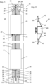
- an elevator system 10 has a first elevator shaft 12 in which a first elevator car 14 and a second elevator car 16 are arranged.
- the first elevator car 14 is located at a lower end position 18 which corresponds to a position of the elevator car 14 on a bottom floor of the building 20 having the elevator system 10 .
- the second elevator car 16 is located at an upper end position 22, which corresponds to a position of the elevator car 16 on a top floor of the building 20. Between the lower end position 18 and the upper end position 22 there are a large number of floors, which are 1 are not shown.
- the elevator system 10 has a running in the vertical direction car guide rail 24 on which the elevator cars 14, 16 during a shift in Elevator shaft 12 are performed. To move the elevator cars 14, 16 in the elevator shaft 12, the elevator system 10 has a total of eight self-contained suspension means 26, of which in FIG 1 four support means 26 are shown.
- the support means 26 are designed as belts and are each guided around a lower deflection roller 28 and an upper deflection roller 30 .
- the two deflection rollers 28, 30 of a support means 26 are arranged vertically one above the other, so that the support means 26 run vertically between the deflection rollers 28, 30.
- the deflection rollers 28, 30 have in particular an effective diameter of less than 100 mm.
- the lower deflection rollers 28 are arranged below the first elevator car 14 and are each connected to a tension weight 32 .
- the tensioning weight 32 acts as a tensioning device with which, on the one hand, the required suspension element pretension is generated and, on the other hand, deviations in the original length of the self-contained suspension element 26 as well as operational plastic length changes of the suspension element 26 are compensated.
- the upper deflection rollers 30 are arranged above the second elevator car 16 and each serve as a traction sheave for a drive machine 34 designed as an electric motor.
- a drive machine 34 is assigned to each suspension element 26, by means of which the suspension element 26 can be driven and displaced.
- the drive machines 34 are controlled by a control device in the form of an elevator control 36 which controls all actuators of the elevator system 10 .
- Each suspension element 26 consists of two suspension element parts 38, 40, the free ends 42 of which are connected by two, in 2 Coupling elements 44 shown enlarged are connected.
- the coupling element 44 consists of two suspension element end connections 46 aligned in opposite directions, which are connected to a connection element 50 having a recess 48 .
- the Tragstoffendtagenen 46 can, for example, according to in the EP 1634842 A2 described suspension element end connections.
- An extendable bolt 60 of a coupling device 58 arranged on an elevator car 14, 16 can dip into the recess 48, with which the coupling device 58 is coupled to the coupling element 44.
- the coupling device 58 can be uncoupled from the coupling element 44 by pulling the bolt 60 out of the recess 48 .
- the Coupling devices 58 are arranged on a floor 51 of the elevator cars 14, 16 and in connection with the 4 described in more detail.
- a coupling element 44 to which a coupling device 58 has coupled has a filled-in square in the figures. In the 1 is thus the second elevator car 16 via a coupling element 44 with the in the 1 connected to the far left suspension means 26.
- the coupling devices prefferably be arranged on the roof of an elevator car.
- the positions of the coupling elements on the support means must then be adjusted accordingly.
- the elevator cars 14, 16 each have a braking device 74, by means of which they can be fixed to the car guide rail 24 and thus within the elevator shaft 12.
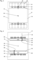
- FIG. 3 a view from above of the first elevator shaft 12 with a total of eight drive machines 34 is shown.
- the drive machines 34 are each drive-connected to a traction sheave in the form of a deflection pulley 30 over which a suspension element 26 runs.
- the reference numbers shown only once In each case four drive machines 34 are arranged on opposite sides of the elevator car 16 , with two drive machines 34 being arranged on different sides of the running car guide rail 24 on each of the opposite sides of the elevator car 16 .
- Drive axles 52 of the drive machines 34 run parallel to one another, with one drive machine each 34 is arranged on one side of the elevator car 16 coaxially to a drive machine 34 on the other side of the elevator car 16 .
- a car door, not shown, of the elevator car 16 is located on one or both free sides 54 of the elevator car 16, on which no drive machines 34 are arranged.
- the elevator control 36 (see 1 ) always actuates two drive machines 34 on opposite sides in the same way or synchronously, so that the support means 26 assigned to them also move or are displaced synchronously.
- Two drive machines 34 are always controlled in the same way, which are arranged diagonally with respect to a center of gravity 56 of the elevator car, for example in 3 the upper, far left drive machine 34 and the lower, far right drive machine 34. With the eight drive machines 34, a total of four elevator cars 14, 16 can be displaced in the first elevator shaft 12 simultaneously and independently of one another.
- each coupling device 58 has a bolt 60 which can be extended and retracted in an actuation direction 62 which is oriented in the direction of the coupling elements 44 .
- the coupling device 58 has an actuating actuator 64, which can be embodied as an electric motor, for example.
- the bolt 60 together with the actuating actuator 64 can be displaced horizontally and perpendicularly to the actuating direction 62 along a rail 66 by means of a positioning actuator 68, which is also designed as an electric motor, for example.
- the bolt 60 is first correctly positioned with respect to the corresponding coupling element 44 . Then the bolt 60 is extended, whereby the bolt 60 dips into the recess 48 of the coupling element 44 . This creates a positive connection between the coupling device 58 and the coupling element 44 and thus between the Elevator car 16 and the support means 26 made. When this form-fitting connection is established, the elevator car 16 can be displaced in the elevator shaft 12 .
- the elevator car 16 is always coupled to two support means 26 which are arranged diagonally with respect to the center of gravity 56 of the elevator car. This takes place in that the elevator car 16 is always coupled to coupling elements 44 which are arranged diagonally with respect to the center of gravity 56 of the elevator car 16 .
- the bolts of the coupling devices cannot be moved.
- the coupling devices have separate bolts for each coupling element, or a coupling device is assigned to precisely one coupling element and thus precisely to one suspension element.
- the drive machines and thus the suspension means can also be arranged on a side of the elevator car opposite the car door and thus the shaft door.
- an elevator car has, in particular, only one coupling device, so that an elevator car is coupled to only one suspension element for displacement in the elevator shaft.
- the elevator system 10 has a second elevator shaft (not shown) that is arranged parallel to the first elevator shaft 12 .
- the second elevator shaft is designed analogously to the first elevator shaft 12 .
- the relocation of the elevator cars 14, 16 in the second elevator shaft is implemented analogously to the relocation in the first elevator shaft 12. In the first elevator shaft 12, the elevator cars 14, 16 are only shifted upwards and in the second elevator shaft only downwards.
- the elevator system 10 has two transfer devices, not shown, by means of which the elevator cars 14, 16 can be moved from the first to the second or from the second to the first elevator shaft.
- the transfer facilities can, in particular, correspond to the transfer facilities in Form of horizontal displacement units EP 2219985 B1 be executed.
- a coupling element 46 is guided in the shift in the elevator shaft 12 by a management system 80, which in connection with the Figures 5 - 7 is explained.
- a coupling element 46 is connected to a runner 82 of the guide 80 via a connection 81 .
- the runner 82 is guided in a guide in the form of what is known as a C-rail 83 .
- the C-rail 83 is attached to a shaft wall 84 of the in figure 5 not shown elevator shaft 12 screwed and fixed with it. It thus runs along the shaft wall 84 and is stationary relative to the elevator shaft 12.
- the runner 82 has a first, upper guide roller 85 and a second, lower guide roller 86, which are arranged on a lever 87 pivotable about a lever axis 88.
- first guide roller 85 is mounted on a first roller axis 89 and the second guide roller 86 is mounted on a second roller axis 90 .
- the two roller axles 89 , 90 are arranged on opposite sides of the lever 87 with respect to the lever axle 88 .
- the C-rail 83 has two opposite side walls 91 which protrude from the shaft wall 84 into the elevator shaft 12 .
- Insides 92 of the side panels 91 have a concave contour.
- the two guide rollers 85, 86 of the runner 82 have a corresponding convex profile on their outer circumference, so that the guide rollers 85, 86 move from the C-rail 83 in a first direction 93 towards the shaft wall 84 and away from it and in a second direction 94 are guided horizontally transversely to or along the shaft wall 84.
- the runner 82 has a third spring arrangement 95 with an upper, fifth spring 96 (only in 6 visible) and a lower, sixth spring 79 (only in figure 5 visible)
- the springs 96, 79 are tensioned between the lever 87 and the coupling element 46 in such a way that the guide rollers 85, 86 are pressed against the insides 92 of the side walls 91 of the C-rail 83.
- the spring assembly 95 is the 7 shown more clearly.
- the pin 97 is secured by a cap 100 screwed onto the end of the pin 97 opposite the runner 82.
- the pin 97 can be displaced to a limited extent in the recess 98 in the direction of the shaft wall 84 and away from the shaft wall 84 . It can therefore be displaced in the first direction 93 mentioned above. A first relative movement between the rotor 82 and the coupling element 46 in the first direction 93 is thus possible.
- a first spring 101 in the form of a coil spring is arranged around the pin 97 between the lever 87 of the rotor 82 and the pivot arm 99 .
- the first spring 101 pushes the lever 87 and thus the runner 82 in the direction of the shaft wall 84.
- a second spring 102 in the form of a helical spring is arranged around the pin 97 between the pivot arm 99 and the cap 100 of the pin 97.
- the second spring 102 pushes the cap 100 of the pin 97 and thus the lever 87 and the runner 82 away from the wall 84 of the shaft.
- the first spring 101 and the second spring 102 thus form a first spring arrangement 103 of the connection 81.
- the pivot arm 99 having the through-opening 98 can be pivoted about a pivot axis 104 which runs parallel to the through-opening 98 and thus to the pin 97 .
- the swivel arm 99 can thus perform a swiveling movement along a circular path around the mentioned swivel axis 104 and thus along the shaft wall 84 to a limited extent.
- the possible movement of the swivel arm 99 thus has a horizontal component as well as a vertical one.
- the lever 87 of the rotor 82 is also pivoted with the pin 97 relative to the pivot axis 104 and thus relative to the coupling element 46 .
- the runner 82 When pivoting the pivot arm 99 about the pivot axis 104, the runner 82 thus performs a second relative movement with respect to the coupling element 46, which, as described, has a horizontal component.
- a second spring arrangement 106 acts on the swivel arm 99, which is only 7 is shown.
- the spring assembly 106 includes a third spring 107 between Pivot arm 99 and a vertically extending component 108 of the coupling element 46 is arranged so that the pivot arm 99 in the 7 pushes to the left.
- the spring arrangement 106 also has a fourth spring 109 which is arranged on the side of the component 108 of the coupling element 46 facing away from the pivot arm 99 in such a way that it holds the pivot arm 99 in the 7 pushes to the right.
- the third spring arrangement 95 is also clearly visible.
- the upper, fifth spring 96 and the lower, sixth spring 79 are tensioned between the outwardly projecting hook 110 of the lever 87 and the vertical component 108 of the coupling element 46 in such a way that the guide rollers 85, 86 press against the inner sides 92 of the side walls 91 of the C Rail 83 are pressed.
Description
Die Erfindung betrifft ein Aufzugsystem mit den Merkmalen des Oberbegriffs des Anspruchs 1.The invention relates to an elevator system having the features of the preamble of claim 1.
Die
Die Aufzugkabinen werden in dem genannten Aufzugschacht nur in eine Richtung, also nur nach oben oder nur nach unten verlagert. Um einen umlaufenden Betrieb der Aufzugkabinen realisieren zu können, verfügt das Aufzugsystem über einen weiteren Aufzugschacht. Die Aufzugkabinen können zwischen den beiden Aufzugschächten mittels einer Transfereinrichtung horizontal verschoben werden. Im Betrieb des Aufzugsystems koppelt sich eine Aufzugkabine an einer unteren bzw. einer oberen Endposition über ihre Kopplungseinrichtung und ein Ankoppelelement an ein Tragmittel an und wird über das Tragmittel von der zugehörigen Antriebsmaschine nach oben bzw. unten verlagert, bis sie die obere bzw. untere Endposition erreicht hat. Dort koppelt sich die Aufzugkabine vom Tragmittel ab und wird von einer Transfereinrichtung in den Aufzugschacht für die andere Verlagerungsrichtung horizontal in den anderen Aufzugschachtverschoben.The elevator cars are only moved in one direction in the named elevator shaft, ie only upwards or only downwards. In order to be able to operate the elevator cabins in a circulating manner, the elevator system has an additional elevator shaft. The elevator cars can be moved horizontally between the two elevator shafts by means of a transfer device. During operation of the elevator system, an elevator car is coupled to a suspension element at a lower or an upper end position via its coupling device and a coupling element and is displaced upwards or downwards by the associated drive machine via the suspension element until it reaches the upper or lower end position has reached. There the elevator car is uncoupled from the suspension element and is horizontally shifted by a transfer device into the elevator shaft for the other direction of displacement into the other elevator shaft.
Die beschriebenen Ankoppelelemente der Tragmittel können wie oben beschrieben über eine Kopplungseinrichtung mit einer Aufzugkabine verbunden sein. Diese Ankoppelelemente werden im Folgenden als verbundene Ankoppelelemente bezeichnet. Die Ankoppelelemente können auch wie oben beschrieben nicht mit einer Aufzugkabine gekoppelt sein. Diese Ankoppelelemente werden im Folgenden als freie Ankoppelelemente bezeichnet.As described above, the described coupling elements of the suspension means can be connected to an elevator car via a coupling device. This Coupling elements are referred to below as connected coupling elements. As described above, the coupling elements can also not be coupled to an elevator car. These coupling elements are referred to below as free coupling elements.
Beim Betrieb des genannten Aufzugsystems, also beim Verlagern einer oder mehrerer Aufzugkabinen im Aufzugschacht, werden sowohl verbundene, als auch freie Ankoppelelemente im Aufzugschacht verlagert. Beim Verlagern der Aufzugkabinen kann es zu Schwingungen der Tragmittel kommen. Die verbundenen Ankoppelelemente werden durch ihre Kopplung mit einer Aufzugkabine am Schwingen gehindert. Die freien Ankoppelelemente würden ohne geeignete Gegenmassnahmen die Schwingungen des Tragmittels mitmachen. Dies könnte dazu führen, dass ein freies Ankoppelelement beim Vorbeifahren an einer Aufzugkabine an dieser anschlägt oder dass ein freies Ankoppelelement am Aufzugschacht anschlägt. Ein derartiges Anschlagen könnte zum einen zu einem hörbaren Schlag führen und könnte zum anderen Schäden an der Aufzugkabine und/oder dem Aufzugschacht und/oder dem Ankoppelelement hervorrufen.When the mentioned elevator system is in operation, ie when one or more elevator cars are shifted in the elevator shaft, both connected and free coupling elements are shifted in the elevator shaft. When shifting the elevator cabins, vibrations in the suspension elements can occur. The connected coupling elements are prevented from swinging by their coupling to an elevator car. Without suitable countermeasures, the free coupling elements would follow the vibrations of the suspension element. This could result in a free coupling element hitting an elevator car when driving past it, or in a free coupling element hitting the elevator shaft. Such an impact could on the one hand lead to an audible impact and on the other hand could cause damage to the elevator car and/or the elevator shaft and/or the coupling element.
Demgegenüber ist es insbesondere die Aufgabe der Erfindung, ein Aufzugsystem vorzuschlagen, welches einen komfortablen und gleichzeitig zuverlässigen Betrieb des Aufzugsystems ermöglicht. Erfindungsgemäss wird diese Aufgabe mit einem Aufzugsystem mit den Merkmalen des Anspruchs 1 gelöst.In contrast, it is the object of the invention, in particular, to propose an elevator system that enables comfortable and at the same time reliable operation of the elevator system. According to the invention, this object is achieved with an elevator system having the features of claim 1.
Das erfindungsgemässe Aufzugsystem verfügt über eine Aufzugkabine, die in einem Aufzugschacht verlagerbar ist, ein im Aufzugschacht verlaufendes Tragmittel, eine dem Tragmittel zugeordnete Antriebsmaschine und eine an der Aufzugkabine angeordnete ansteuerbare Kopplungseinrichtung. Das Tragmittel weist ein Ankoppelelement auf, an welches sich die Kopplungseinrichtung ankoppeln und abkoppeln kann, womit eine Antriebsverbindung zwischen der Aufzugkabine und dem Tragmittel herstellbar und lösbar ist. Die angekoppelte Aufzugkabine kann mittels des von der Antriebsmaschine antreibbaren Tragmittels im Aufzugschacht verlagert werden.The elevator system according to the invention has an elevator car that can be displaced in an elevator shaft, a suspension element running in the elevator shaft, a drive machine assigned to the suspension element, and a controllable coupling device arranged on the elevator cabin. The suspension element has a coupling element to which the coupling device can be coupled and uncoupled, with which a drive connection between the elevator car and the suspension element can be established and released. The coupled elevator car can be displaced in the elevator shaft by means of the suspension means that can be driven by the drive machine.
Erfindungsgemäss weist das Aufzugsystem ein Führungssystem zum Führen des Ankoppelelements bei einer Verlagerung im Aufzugschacht auf. Das Führungssystem verfügt über eine gegenüber dem Aufzugschacht ortsfeste Führung und einen mit dem Ankoppelelement über eine Anbindung verbundenen, entlang der Führung geführten Läufer. Die Anbindung zwischen Ankoppelelement und Läufer ist so ausgeführt, dass eine Relativbewegung zwischen Läufer und Ankoppelelement möglich ist. Die genannte Anbindung kann damit auch als eine flexible Anbindung bezeichnet werden.According to the invention, the elevator system has a guide system for guiding the coupling element when it is displaced in the elevator shaft. The management system has a stationary guide compared to the elevator shaft and one with the Coupling element connected via a connection and guided along the guide. The connection between the coupling element and the runner is designed in such a way that a relative movement between the runner and the coupling element is possible. The mentioned connection can thus also be referred to as a flexible connection.
Das genannte Führungssystem verhindert vorteilhafterweise ein Anschlagen eines freien Ankoppelelements an einer Aufzugkabine und am Aufzugschacht während einer Verlagerung im Aufzugschacht und ermöglicht damit einen besonders komfortablen Betrieb des Aufzugsystems. Verbundene Ankoppelelemente sind fest an eine Aufzugkabine gekoppelt und machen damit alle Bewegungen der entsprechenden Aufzugkabine mit. Aufzugkabinen werden beim Verlagern im Aufzugschacht üblicherweise entlang von Kabinen-Führungsschienen geführt, die gegenüber der Führung des Ankoppelelements ausgerichtet werden können. Trotzdem kann es zu einer Verschiebung und/oder Verkippung der entsprechenden Aufzugkabine gegenüber der Führung des Ankoppelelements kommen. Derartige Verschiebungen und/oder Verkippungen können beispielsweise durch eine ungleichmässige Lastverteilung innerhalb der Kabine hervorgerufen werden. Die erfindungsgemässe flexible Anbindung des Ankoppelelements an den Läufer ermöglicht einen Ausgleich der beschriebenen Verschiebung und/oder Verkippung der Aufzugkabine und damit des Ankoppelelements gegenüber der Führung des Führungssystems des Ankoppelelements. Da die Aufzugkabine bei der beschriebenen Verschiebung und/oder Verkippung auf Grund ihrer Masse grosse Kräfte auf das Ankoppelelement ausüben kann, könnte es ohne den beschriebenen Ausgleich zu Beschädigungen am Führungssystem des Ankoppelelements kommen. Beispielsweise könnte der Läufer und/oder die Führung beschädigt werden, was zu einem Ausfall des Aufzugssystems führen kann. Die erfindungsgemässe flexible Anbindung des Läufers an das Ankoppelelement verhindert derartige Beschädigungen des Führungssystems des Ankoppelelements und damit Ausfälle des Aufzugsystems. Es wird damit neben einem besonders komfortablen auch ein besonders zuverlässiger Betrieb des Aufzugsystems ermöglicht.The guide system mentioned advantageously prevents a free coupling element from hitting an elevator car and the elevator shaft during displacement in the elevator shaft and thus enables particularly comfortable operation of the elevator system. Connected coupling elements are firmly coupled to an elevator car and thus participate in all movements of the corresponding elevator car. When moving in the elevator shaft, elevator cars are usually guided along car guide rails, which can be aligned with respect to the guide of the coupling element. Nevertheless, the corresponding elevator car can shift and/or tilt relative to the guidance of the coupling element. Such displacements and/or tilting can be caused, for example, by uneven load distribution within the cabin. The flexible connection of the coupling element to the runner according to the invention enables compensation for the described shifting and/or tilting of the elevator car and thus of the coupling element with respect to the guidance of the guide system of the coupling element. Since the elevator car can exert large forces on the coupling element during the described shifting and/or tilting due to its mass, damage to the guide system of the coupling element could occur without the compensation described. For example, the runner and/or the guide could be damaged, which could lead to failure of the elevator system. The flexible connection of the runner to the coupling element according to the invention prevents such damage to the guide system of the coupling element and thus failures of the elevator system. In addition to particularly convenient operation, this also enables particularly reliable operation of the elevator system.
Unter einer gegenüber dem Aufzugschacht ortsfesten Führung soll in diesem Zusammenhang verstanden werden, dass die Führung im Aufzugschacht nicht beweglich ist. Die Führung kann beispielsweise als eine Führungsschiene ausgeführt sein, die an einer Schachtwand des Aufzugschachts fixiert, beispielsweise angeschraubt ist. Es ist auch möglich, dass die Führung von der Schachtwand selbst gebildet wird. Dazu kann die Schachtwand beispielsweise eine spezielle Führungsfläche aufweisen.In this context, a guide that is stationary relative to the elevator shaft is to be understood as meaning that the guide is not movable in the elevator shaft. The guide can be designed, for example, as a guide rail that is fixed, for example screwed, to a shaft wall of the elevator shaft. It is also possible that the guide is formed by the shaft wall itself. For this purpose, the shaft wall can have a special guide surface, for example.
Der Läufer kann auch als eine Laufkatze bezeichnet werden. Der Läufer kann beispielsweise eine oder mehrere Führungsrollen aufweisen, die auf der Führung abrollen und damit von ihr geführt werden. Es ist auch möglich, dass der Läufer eine Gleitfläche aufweist, an der die Führung entlang gleitet und damit von ihr geführt wird.The runner can also be referred to as a trolley. The runner can have, for example, one or more guide rollers that roll on the guide and are thus guided by it. It is also possible for the runner to have a sliding surface along which the guide slides and is thus guided by it.
Die genannte Anbindung, über die der Läufer mit dem Ankoppelelement verbunden ist, kann beispielsweise als eine Achse in Form eines Stifts ausgeführt sein, welcher zumindest in einer Richtung gegenüber dem Ankoppelelement beweglich ist. Die genannte Relativbewegung zwischen Läufer und Ankoppelelement weist insbesondere wenigstens eine horizontale Komponente auf. Sie ist ausserdem insbesondere begrenzt.Said connection, via which the runner is connected to the coupling element, can be designed, for example, as an axle in the form of a pin, which can be moved in at least one direction relative to the coupling element. The mentioned relative movement between the runner and the coupling element has in particular at least one horizontal component. It is also particularly limited.
Das Aufzugsystem weist insbesondere mehr als eine Aufzugkabine, also beispielsweise zwei bis acht Aufzugkabinen auf, welche grundsätzlich identisch aufgebaut sind und alle eine Kopplungseinrichtung aufweisen. Das Aufzugsystem weist insbesondere mehr als einen Aufzugschacht, speziell zwei Aufzugschächte auf, zwischen welchen die Aufzugkabinen mittels Transfereinrichtungen verschoben werden können. Es ist insbesondere an beiden Enden der Aufzugschächte jeweils eine Transferstation angeordnet, so dass ein umlaufender Betrieb der Aufzugkabinen möglich ist. Dazu werden die Aufzugkabinen in einem ersten Aufzugschacht nur von unten nach oben und in einem zweiten Aufzugschacht nur von oben nach unten verlagert. Bei Erreichen des oberen bzw. unteren Ende des jeweiligen Aufzugschachts werden die Aufzugkabinen mittels einer Transferstation in den anderen Aufzugschacht verschoben.In particular, the elevator system has more than one elevator car, ie, for example, two to eight elevator cars, which are basically identical in structure and all have a coupling device. In particular, the elevator system has more than one elevator shaft, specifically two elevator shafts, between which the elevator cars can be moved by means of transfer devices. In particular, a transfer station is arranged at both ends of the elevator shafts, so that a circulating operation of the elevator cars is possible. For this purpose, the elevator cars are shifted only from bottom to top in a first elevator shaft and only from top to bottom in a second elevator shaft. When the upper or lower end of the respective elevator shaft is reached, the elevator cars are moved to the other elevator shaft by means of a transfer station.
Der Aufzugschacht bzw. die Aufzugschächte sind in oder an einem Gebäude angeordnet und verlaufen hauptsächlich in vertikaler Richtung, so dass die Aufzugkabinen bei einer Verlagerung im Aufzugschacht hauptsächlich vertikal verlagert werden.The elevator shaft or elevator shafts are arranged in or on a building and run mainly in the vertical direction, so that the elevator cars are mainly displaced vertically when they are moved in the elevator shaft.
Das Tragmittel ist insbesondere in sich geschlossen, also beispielsweise ringförmig ausgeführt. Es kann damit auch als endlos bezeichnet werden. Das bedeutet aber nicht zwingend, dass es als ein homogener Ring ausgeführt ist oder nur aus einem Stück besteht. Das Tragmittel ist insbesondere um eine untere und eine obere Umlenkrolle geführt, wobei mindestens eine Umlenkrolle als Antriebsrolle oder Treibscheibe dient, über die das Tragmittel von der ihm zugeordneten Antriebsmaschine angetrieben werden kann. Die Umlenkrollen weisen insbesondere einen Wirkdurchmesser von weniger als 100 mm auf. Derart geringe Wirkdurchmesser einer als Treibscheibe dienenden Umlenkrolle ermöglichen einen getriebelosen Antrieb des Tragmittels, der wenig Einbauraum beansprucht. Am Tragmittel kann insbesondere eine Spannvorrichtung angeordnet sein, mit welcher einerseits die erforderliche Tragmittelvorspannung erzeugt und andererseits Abweichungen in der ursprünglichen Länge des in sich geschlossenen Tragmittels sowie betriebsbedingte plastische Längenänderungen des Tragmittels ausgeglichen werden. Die erforderlichen Spannkräfte lassen sich beispielsweise mit Spanngewichten, Gasfedern oder Metallfedern erzeugen.The suspension element is in particular self-contained, that is, for example, designed in the shape of a ring. It can thus also be described as endless. However, this does not necessarily mean that it is designed as a homogeneous ring or consists of only one piece. The suspension means is in particular a lower and an upper deflection roller out, with at least one deflection roller serving as a drive roller or traction sheave, via which the suspension element can be driven by the drive machine assigned to it. In particular, the deflection rollers have an effective diameter of less than 100 mm. Such small effective diameters of a deflection pulley serving as a traction sheave enable a gearless drive of the suspension element, which requires little installation space. In particular, a tensioning device can be arranged on the suspension element, with which on the one hand the required suspension element pretension is generated and on the other hand deviations in the original length of the self-contained suspension element and operational plastic length changes of the suspension element are compensated for. The required tensioning forces can be generated, for example, with tensioning weights, gas springs or metal springs.
Die Antriebsmaschine ist insbesondere als ein Elektromotor ausgeführt, der von einer Aufzugsteuerung angesteuert wird. Die Aufzugsteuerung steuert den kompletten Betrieb des Aufzugsystems, sie steuert also alle ansteuerbaren Komponenten des Aufzugsystems an und ist mit Schaltern und Sensoren des Aufzugsystems verbunden. Die Aufzugsteuerung kann als eine einzige zentrale Aufzugsteuerung ausgeführt sein oder aus mehreren dezentralen Steuerung bestehen, die für Teilaufgaben zuständig sind.The drive machine is designed in particular as an electric motor that is controlled by an elevator controller. The elevator control controls the entire operation of the elevator system, so it controls all controllable components of the elevator system and is connected to switches and sensors of the elevator system. The elevator control can be designed as a single central elevator control or consist of several decentralized controls that are responsible for subtasks.
Die an der oder den Aufzugkabinen angeordneten Kopplungseinrichtungen sind insbesondere an einem Boden oder einem Dach der Aufzugkabinen angeordnet und werden von der oben genannten Aufzugsteuerung angesteuert. Die Ankopplung an ein Ankoppelelement des Tragmittels in einer angekoppelten Position der Kopplungseinrichtung erfolgt insbesondere formschlüssig, wobei auch eine reibschlüssige Ankopplung denkbar ist. Das Ankoppelelement verfügt insbesondere über eine hauptsächlich horizontal orientierte Ausnehmung, in die beispielsweise in eine Betätigungsrichtung ein aus- und einfahrbarer Bolzen der Kopplungseinrichtung eintauchen kann. Die Kopplungseinrichtung ist in diesem Fall in ihrer angekoppelten Position, wenn der Bolzen der Kopplungseinrichtung in die Ausnehmung des Ankoppelelements eintaucht und in ihrer abgekoppelten Position, wenn der Bolzen nicht in die Ausnehmung eintaucht.The coupling devices arranged on the elevator car(s) are arranged in particular on a floor or a roof of the elevator car and are controlled by the elevator control mentioned above. The coupling to a coupling element of the suspension element in a coupled position of the coupling device takes place in particular in a form-fitting manner, with a friction-fitting coupling also being conceivable. The coupling element has, in particular, a mainly horizontally oriented recess into which, for example, an extendable and retractable bolt of the coupling device can enter in an actuation direction. In this case, the coupling device is in its coupled position when the bolt of the coupling device enters the recess of the coupling element and in its uncoupled position when the bolt does not enter the recess.
Über die Kopplungseinrichtung und das Ankoppelelement kann damit eine form- oder reibschlüssige Verbindung zwischen der Aufzugkabine und dem Tragmittel hergestellt werden, so dass bei einer Verlagerung bzw. Bewegung des Treibmittels auch die Aufzugkabine verlagert wird. Damit ist eine Antriebsverbindung zwischen der Aufzugkabine und dem Tragmittel und damit letztlich zwischen der Aufzugkabine und der dem Tragmittel zugeordneten Antriebsmaschine herstellbar und auch wieder lösbar. Die Kopplungseinrichtungen werden insbesondere so angesteuert, dass zumindest während der Verlagerung einer Aufzugkabine an ein (einziges) Tragmittel nur eine Aufzugkabine angekoppelt ist. Von einem (einzigen) Tragmittel wird damit insbesondere immer nur eine (einzige) Aufzugkabine im Schacht verlagert.A positive or frictional connection between the elevator car and the suspension element can thus be produced via the coupling device and the coupling element be so that with a shift or movement of the propellant and the elevator car is shifted. A drive connection between the elevator car and the suspension element, and thus ultimately between the elevator car and the drive machine assigned to the suspension element, can thus be established and also released again. The coupling devices are controlled in particular in such a way that, at least during the displacement of an elevator car, only one elevator car is coupled to a (single) suspension element. In particular, only one (single) elevator car is ever shifted in the shaft by a (single) suspension element.
Ein Ankoppelelement eines Tragmittels ist insbesondere als ein Verbindungselement ausgeführt, welches zwei freie Enden des Tragmittels miteinander verbindet. Die Verwendung eines in sich geschlossenen Tragmittels ermöglicht den Verzicht auf ein Gegengewicht, das an der Aufzugkabine vorbeigeführt werden muss, was einen kleinen Querschnitt des Aufzugschachts ermöglicht. Ausserdem erfüllt das so ausgeführte Ankoppelelement eine Doppelfunktion. Es dient zum einen der Ankopplung der Aufzugkabine an das Tragmittel und zum anderen der einfachen und kostengünstigen Realisierung des geschlossenen Tragmittels.A coupling element of a suspension element is designed in particular as a connecting element which connects two free ends of the suspension element to one another. The use of a self-contained suspension means makes it possible to dispense with a counterweight that has to be guided past the elevator car, which allows for a small cross-section of the elevator shaft. In addition, the coupling element designed in this way fulfills a dual function. On the one hand, it serves to couple the elevator car to the suspension element and, on the other hand, to realize the closed suspension element in a simple and cost-effective manner.
Das Ankoppelelement erfüllt insbesondere die Funktion eines so genannten Riemenschlosses oder eines Seilverbinders. Damit kann sehr einfach, kostengünstig und sicher aus einem ursprünglich offenen, langgestreckten Tragmittel durch Verbinden der beiden freien Enden mit dem Ankoppelelement ein in sich geschlossenes Tragmittel hergestellt werden. Das Ankoppelelement kann beispielsweise zwei miteinander verbundene Tragmittelendverbindungen aufweisen, welche beispielsweise entsprechend der
In Ausgestaltung der Erfindung verläuft die Führung des Führungssystems entlang einer Schachtwand des Aufzugschachts. Die genannte Anbindung zwischen Ankoppelelement und Läufer ist so ausgeführt, dass eine erste Relativbewegung zwischen Läufer und Ankoppelelement mit zumindest einer Komponente in Richtung zur genannten Schachtwand hin und von der Schachtwand weg möglich ist. Damit können vorteilhafterweise häufig vorkommende Bewegungen der Aufzugkabine und damit des Ankoppelelements in Richtung der Schachtwand und von der Schachtwand weg ausgeglichen werden. Das ermöglicht einen besonders sicheren Betrieb des Aufzugsystems.In an embodiment of the invention, the guidance of the guidance system runs along a shaft wall of the elevator shaft. Said connection between the coupling element and the runner is designed in such a way that a first relative movement between the runner and the coupling element is possible with at least one component in the direction towards the said shaft wall and away from the shaft wall. With that can advantageously frequently occurring movements of the elevator car and thus of the coupling element in the direction of the shaft wall and away from the shaft wall. This enables a particularly safe operation of the elevator system.
Die genannte Komponente der Richtung verläuft insbesondere hauptsächlich senkrecht zur Schachtwand und damit hauptsächlich horizontal. Die genannte Relativbewegung verläuft insbesondere nur zur Schachtwand hin und von der Schachtwand weg und damit insbesondere nur senkrecht zur Schachtwand. Sie kann aber auch eine Komponente aufweisen, die entlang der Schachtwand ausgerichtet ist, also insgesamt schräg zur Schachtwand oder entlang einer Kreisbahn verlaufen.The named component of the direction runs in particular mainly perpendicularly to the shaft wall and thus mainly horizontally. The relative movement mentioned runs in particular only towards the shaft wall and away from the shaft wall and thus in particular only perpendicularly to the shaft wall. However, it can also have a component that is aligned along the shaft wall, that is to say running at an angle to the shaft wall or along a circular path.
Die Führung ist insbesondere als eine Führungsschiene ausgeführt, die an der Schachtwand fixiert, beispielsweise angeschraubt ist. Die genannte Richtung der Komponente der Relativbewegung verläuft damit auch in Richtung Führungsschiene und von der Führungsschiene weg. Damit gelten die Ausführungen bezüglich der Ausrichtung der Relativbewegung gegenüber der Schachtwand analog für eine Ausrichtung der Relativbewegung gegenüber der Führungsschiene. Die Relativbewegung verläuft auch insbesondere in die oben genannte Betätigungsrichtung, in die ein Bolzen der Kopplungseinrichtung zum Ankoppeln an ein Ankopplungselement aus- und eingefahren werden kann.The guide is designed in particular as a guide rail that is fixed to the shaft wall, for example screwed on. The named direction of the component of the relative movement thus also runs in the direction of the guide rail and away from the guide rail. The statements regarding the alignment of the relative movement with respect to the shaft wall thus apply analogously to an alignment of the relative movement with respect to the guide rail. The relative movement also runs in particular in the above-mentioned actuation direction, in which a bolt of the coupling device can be extended and retracted for coupling to a coupling element.
Unter einer Schachtwand soll in diesem Zusammenhang eine Begrenzung des Aufzugschachts in horizontaler Richtung verstanden werden. Eine Schachtwand ist insbesondere als eine massive Wand, beispielsweise aus Beton ausgeführt. Es ist aber auch möglich, dass eine Schachtwand lediglich aus mehreren Querträgern gebildet wird, an welchen beispielsweise Kabinen-Führungsschienen fixiert werden können. Dies kann insbesondere dann vorkommen, wenn mehrere Aufzugschächte nebeneinander angeordnet sind und die einzelnen Aufzugschächte durch Querträger voneinander abgetrennt werden.In this context, a shaft wall should be understood to mean a delimitation of the elevator shaft in the horizontal direction. A shaft wall is designed in particular as a solid wall, for example made of concrete. However, it is also possible for a shaft wall to be formed solely from a plurality of crossbeams, to which, for example, car guide rails can be fixed. This can occur in particular when several elevator shafts are arranged next to one another and the individual elevator shafts are separated from one another by crossbeams.
In Ausgestaltung der Erfindung weist die Anbindung zwischen Ankoppelelement und Läufer einen Stift auf, der mit dem Läufer gekoppelt und in einer Ausnehmung im Ankoppelelement in Richtung zur genannten Schachtwand hin und von der Schachtwand weg verschiebbar angeordnet ist. Damit wird eine besonders einfache und damit kostengünstige flexible Anbindung ermöglicht.In an embodiment of the invention, the connection between the coupling element and the runner has a pin which is coupled to the runner and in a recess in the coupling element in the direction of the said shaft wall and away from the shaft wall is arranged away slidably. This enables a particularly simple and therefore cost-effective, flexible connection.
Zur Kopplung des genannten Stifts mit dem Läufer kann der Stift am Läufer fixiert, beispielsweise angeschraubt sein. Es ist auch möglich, dass der Läufer als eine Führungsrolle ausgeführt ist, welche drehbar auf dem Stift angeordnet ist. Ausserdem kann der Läufer auch einen Hebel aufweisen, der schwenkbar an dem Stift angeordnet ist.In order to couple said pin to the runner, the pin can be fixed to the runner, for example screwed on. It is also possible that the runner is designed as a guide roller which is rotatably arranged on the pin. In addition, the runner can also have a lever which is pivotably arranged on the pin.
Es ist insbesondere nicht der komplette Stift, sondern nur ein Teil des Stifts in der genannten Ausnehmung angeordnet. Die Ausnehmung ist insbesondere als eine Durchgangsöffnung ausgeführt, durch welche der Stift hindurchragt. Der Stift ist insbesondere gegen ein Verlassen der Durchgangsöffnung gesichert.In particular, not the entire pin but only part of the pin is arranged in said recess. The recess is designed in particular as a through opening through which the pin protrudes. In particular, the pin is secured against leaving the through-opening.
In Ausgestaltung der Erfindung weist die Anbindung eine erste Federanordnung auf, welche so ausgeführt und angeordnet ist, dass sie eine Kraft auf den Läufer in Richtung der ersten Relativbewegung aufbringen kann. Damit können auftretende Relativbewegungen zwischen Läufer und Ankoppelelement in Richtung der ersten Relativbewegung abgefedert werden. Das ermöglicht einen besonders ruhige Führung des Läufers.In an embodiment of the invention, the connection has a first spring arrangement, which is designed and arranged in such a way that it can apply a force to the runner in the direction of the first relative movement. Relative movements that occur between the rotor and the coupling element can thus be cushioned in the direction of the first relative movement. This enables the runner to be guided particularly smoothly.
Die erste Federanordnung verfügt insbesondere über eine erste Feder, welche den Läufer vom Ankoppelelement wegdrückt. Damit kann ein Anstossen des Läufers am Ankoppelelement verhindert werden, was störende Geräusche verursachen könnte. Die erste Federanordnung verfügt insbesondere zusätzlich über eine zweite Feder, welche den Läufer zum Ankoppelelement hinzieht. Damit können auch Relativbewegungen des Läufers vom Ankoppelelement weg abgefedert werden. Ausserdem kann durch eine entsprechende Auslegung der ersten und zweiten Feder eine Ruheposition des Läufers in Richtung der ersten Relativbewegung eingestellt werden, die der Läufer dann einnimmt, wenn keine anderen Kräfte auf ihn wirken.In particular, the first spring arrangement has a first spring which pushes the runner away from the coupling element. This can prevent the rotor from bumping into the coupling element, which could cause annoying noises. In particular, the first spring arrangement also has a second spring, which pulls the runner towards the coupling element. In this way, relative movements of the rotor away from the coupling element can also be cushioned. In addition, a rest position of the runner can be set in the direction of the first relative movement, which the runner assumes when no other forces are acting on it, by appropriately designing the first and second springs.
In Ausgestaltung der Erfindung verläuft die Führung entlang einer Schachtwand des Aufzugschachts. Die Anbindung zwischen Ankoppelelement und Läufer ist so ausgeführt, dass eine zweite Relativbewegung zwischen Läufer und Ankoppelelement entlang der genannten Schachtwand mit zumindest einer horizontalen Komponente möglich ist. Das Ermöglichen einer zweiten Relativbewegung zwischen Läufer und Ankoppelelement ermöglicht einen besonders komfortablen und zuverlässigen Betrieb des Aufzugsystems.In an embodiment of the invention, the guide runs along a shaft wall of the elevator shaft. The connection between the coupling element and the runner is designed in such a way that a second relative movement between the runner and the coupling element along the shaft wall mentioned has at least one horizontal component is possible. The enabling of a second relative movement between the runner and the coupling element enables a particularly comfortable and reliable operation of the elevator system.
Die obigen Ausführungen zur Führung, zur Führungsschiene und zur Schachtwand gelten auch für diese Ausgestaltung der Erfindung.The above statements regarding the guide, the guide rail and the shaft wall also apply to this embodiment of the invention.
Die genannte Relativbewegung kann insbesondere horizontal verlaufen und damit nur eine horizontale Komponente aufweisen. Sie verläuft dann hauptsächlich parallel zur genannten Schachtwand. Sie kann aber auch eine vertikale Komponente aufweisen oder entlang einer Kreisbahn verlaufen.Said relative movement can, in particular, run horizontally and thus only have a horizontal component. It then runs mainly parallel to said shaft wall. However, it can also have a vertical component or run along a circular path.
Die Anbindung zwischen Ankoppelelement und Läufer ist insbesondere so ausgeführt, dass eine erste Relativbewegung zwischen Läufer und Ankoppelelement mit zumindest einer Komponente in Richtung zur genannten Schachtwand hin und von der Schachtwand weg und zusätzlich eine zweite Relativbewegung zwischen Läufer und Ankoppelelement entlang der genannten Schachtwand mit zumindest einer horizontalen Komponente möglich sind. Es ist aber auch möglich, dass nur die genannte erste Relativbewegung oder die genannte zweite Relativbewegung möglich ist.The connection between the coupling element and the runner is designed in particular in such a way that a first relative movement between the runner and the coupling element has at least one component in the direction of the shaft wall mentioned and away from the shaft wall and, in addition, a second relative movement between the rotor and the coupling element along the shaft wall mentioned has at least one component horizontal components are possible. However, it is also possible that only the first relative movement mentioned or the second relative movement mentioned is possible.
In Ausgestaltung der Erfindung führt die Führung den Läufer in Richtung der ersten Relativbewegung und in Richtung der zweiten Relativbewegung zwischen Läufer und Ankoppelelement. Damit wird eine besonders zuverlässige Führung des Läufers und damit des Ankoppelelements ermöglich. Dies führt zu einem besonders komfortablen Betrieb des Aufzugsystems. Unter einer Führung des Läufers in Richtung der ersten und zweiten Relativbewegung soll hierbei verstanden werden, dass der Läufer bezüglich der Führung in Richtung der ersten und zweiten Relativbewegung nicht oder nur in sehr eingeschränkten Mass verlagert werden kann. Bei einer vertikal verlaufenden Führung kann damit der Läufer hauptsächlich auch nur vertikal verlagert werden.In an embodiment of the invention, the guide guides the runner in the direction of the first relative movement and in the direction of the second relative movement between the runner and the coupling element. This enables a particularly reliable guidance of the runner and thus of the coupling element. This leads to a particularly comfortable operation of the elevator system. Guidance of the runner in the direction of the first and second relative movement is to be understood here as meaning that the runner cannot be displaced or can only be displaced to a very limited extent with respect to the guide in the direction of the first and second relative movement. In the case of a vertically running guide, the runner can thus be displaced mainly only vertically.
In Ausgestaltung der Erfindung ist die genannte Ausnehmung, welche den oben genannten Stift zumindest teilweise aufnimmt, an einem Schwenkarm des Ankoppelelements angeordnet, der entlang der genannten Schachtwand verschwenkbar ist. Damit lassen sich die beiden beschriebenen Relativbewegungen besonders einfach und kostengünstig realisieren.In an embodiment of the invention, said recess, which at least partially accommodates the above-mentioned pin, is arranged on a swivel arm of the coupling element, which can be swiveled along said shaft wall. This allows the two relative movements described to be particularly simple and implement at low cost.
In Ausgestaltung der Erfindung weist die Anbindung eine zweite Federanordnung auf, welche so ausgeführt und angeordnet ist, dass sie eine Kraft auf den Läufer in Richtung der zweiten Relativbewegung aufbringen kann. Damit können auftretende Relativbewegungen zwischen Läufer und Ankoppelelement in Richtung der zweiten Relativbewegung abgefedert werden. Das ermöglicht einen besonders ruhige Führung des Läufers.In an embodiment of the invention, the connection has a second spring arrangement, which is designed and arranged in such a way that it can apply a force to the runner in the direction of the second relative movement. Relative movements that occur between the rotor and the coupling element can thus be cushioned in the direction of the second relative movement. This enables the runner to be guided particularly smoothly.
Die zweite Federanordnung verfügt insbesondere über eine dritte und eine vierte Feder, welche entgegengesetzt zueinander wirken. Durch eine entsprechende Auslegung der dritten und vierten Feder kann eine Ruheposition des Läufers in Richtung der zweiten Relativbewegung eingestellt werden, die der Läufer dann einnimmt, wenn keine anderen Kräfte auf ihn wirken.The second spring arrangement has, in particular, a third and a fourth spring which act in opposite directions to one another. By appropriately designing the third and fourth springs, a rest position of the runner can be set in the direction of the second relative movement, which the runner assumes when no other forces are acting on it.
In Ausgestaltung der Erfindung weisen die Führung eine Seitenwange und der Läufer eine Führungsrolle auf, wobei die Führungsrolle an einer Innenseite der Seitenwange der Führung geführt wird. Damit wird eine einfache Realisierung der Führung ermöglicht.In an embodiment of the invention, the guide has a side cheek and the runner has a guide roller, the guide roller being guided on an inside of the side cheek of the guide. This enables a simple implementation of the guide.
Unter einer Seitenwange soll in diesem Zusammenhang ein Abschnitt der Führung verstanden werden, der von der Schachtwand weg in den Aufzugschacht hineinragt.In this context, a side cheek is to be understood as meaning a section of the guide which protrudes away from the shaft wall and into the elevator shaft.
In Ausgestaltung der Erfindung weist die Führung insbesondere eine erste Seitenwange und eine gegenüberliegende zweite Seitenwange und der Läufer verfügt über eine erste Führungsrolle und eine zweite Führungsrolle. Die erste Führungsrolle wird an der Innenseite der ersten Seitenwange der Führung und die zweite Führungsrolle an der Innenseite der zweiten Seitenwange der Führung geführt. Die Führung mittels zweier Führungsrollen ermöglicht eine besonders gute Führung des Ankoppelelements und damit einen besonders komfortablen Betrieb des Aufzugsystems.In an embodiment of the invention, the guide has in particular a first side cheek and an opposite second side cheek and the runner has a first guide roller and a second guide roller. The first guide roller is guided on the inside of the first side cheek of the guide and the second guide roller on the inside of the second side cheek of the guide. The guidance by means of two guide rollers enables a particularly good guidance of the coupling element and thus a particularly comfortable operation of the elevator system.
In Ausgestaltung der Erfindung ist die erste Führungsrolle auf einer ersten Rollenachse und die zweite Führungsrolle auf einer zweiten Rollenachse gelagert. Die beiden Rollenachsen sind an einem um eine Hebelachse schwenkbaren Hebel des Läufers angeordnet, wobei die beiden Rollenachsen insbesondere an bezüglich der Hebelachse gegenüberliegende Seiten des Hebels angeordnet sind. Damit können durch ein Verschwenken des genannten Hebels die beiden Führungsrollen in Richtung der Seitenwangen der Führung geschwenkt oder von ihnen weg geschwenkt werden.In an embodiment of the invention, the first guide roller is mounted on a first roller axis and the second guide roller is mounted on a second roller axis. The two roller axes are arranged on a lever of the runner that can be pivoted about a lever axis, with the two roller axes being in particular on the lever axis opposite sides of the lever are arranged. Thus, by pivoting said lever, the two guide rollers can be pivoted in the direction of the side walls of the guide or pivoted away from them.
In Ausgestaltung der Erfindung wird die Hebelachse des schwenkbaren Hebels des Läufers zumindest teilweise vom oben beschriebenen Stift der Anbindung zwischen Ankoppelelement und Läufer gebildet. Damit hat der Stift eine Doppelfunktion, was eine einfache und kostengünstige Realisierung der Anbindung des Läufers an das Ankoppelelement ermöglicht.In an embodiment of the invention, the lever axis of the pivotable lever of the runner is at least partially formed by the above-described pin of the connection between the coupling element and the runner. The pin thus has a dual function, which enables the rotor to be connected to the coupling element in a simple and cost-effective manner.
In Ausgestaltung der Erfindung weist der Läufer eine dritte Federanordnung auf, welche so ausgeführt und angeordnet ist, dass die Führungsrollen gegen die Innenseiten der Seitenwangen der Führung gedrückt werden. Damit wird sichergestellt, dass die Führungsrollen immer an den Seitenwangen der Führung abrollen und sich nicht von ihnen lösen können. Dies ermöglicht eine besonders gute Führung des Ankoppelelements und damit einen besonders komfortablen Betrieb des Aufzugsystems.In an embodiment of the invention, the runner has a third spring arrangement, which is designed and arranged in such a way that the guide rollers are pressed against the insides of the side walls of the guide. This ensures that the guide rollers always roll on the side walls of the guide and cannot detach from them. This enables a particularly good guidance of the coupling element and thus a particularly comfortable operation of the elevator system.
Die dritte Federanordnung verfügt über eine fünfte Feder und insbesondere zusätzlich über eine sechste Feder, welche insbesondere zwischen dem Hebel des Läufers und dem Ankoppelelement so gespannt sind, dass sie die Führungsrollen gegen die Innenseiten der Seitenwangen der Führung drücken. Sofern eine sechste Feder vorhanden ist, wirkt diese gleichsinnig mit der fünften Feder.The third spring arrangement has a fifth spring and in particular an additional sixth spring, which are tensioned in particular between the lever of the runner and the coupling element in such a way that they press the guide rollers against the insides of the side walls of the guide. If there is a sixth spring, it acts in the same direction as the fifth spring.
In Ausgestaltung der Erfindung weisen die Innenseiten der Seitenwangen der Führung eine konkave Kontur und die Führungsrollen des Läufers ein korrespondierendes konvexes Profil auf. Damit wird zum einen ein möglichst grossflächiger Kontakt zwischen Führungsrollen und Führung gewährleistet, was eine besonders gute Führung des Ankoppelelements und damit einen besonders komfortablen Betrieb des Aufzugsystems ermöglicht. Ausserdem ermöglichen die Seitenwangen auf Grund ihrer konkaven Kontur eine gleichzeitige Führung in die genannte erste Richtung und die genannte zweite Richtung der Relativbewegung zwischen Läufer und Ankoppelelement. Damit kann auf einfache und kostengünstige Weise eine sehr exakte Führung des Ankoppelelements und damit ein besonders komfortabler Betrieb des Aufzugsystems ermöglicht werden.In an embodiment of the invention, the insides of the side walls of the guide have a concave contour and the guide rollers of the runner have a corresponding convex profile. On the one hand, this ensures that the contact between the guide rollers and the guide is as large as possible, which enables particularly good guidance of the coupling element and thus particularly convenient operation of the elevator system. In addition, due to their concave contour, the side walls enable simultaneous guidance in the named first direction and the named second direction of the relative movement between the runner and the coupling element. In this way, very precise guidance of the coupling element and thus particularly convenient operation of the elevator system can be made possible in a simple and cost-effective manner.
Weitere Vorteile, Merkmale und Einzelheiten der Erfindung ergeben sich anhand der nachfolgenden Beschreibung von Ausführungsbeispielen sowie anhand der Zeichnungen, in welchen gleiche oder funktionsgleiche Elemente mit identischen Bezugszeichen versehen sind. Die Zeichnungen sind lediglich schematisch und nicht massstabsgetreu.Further advantages, features and details of the invention result from the following description of exemplary embodiments and from the drawings, in which identical or functionally identical elements are provided with identical reference symbols. The drawings are merely schematic and not true to scale.
Dabei zeigen:
- Fig. 1
- einen ersten Aufzugschacht eines Aufzugssystems mit einer ersten und einer zweiten Aufzugkabine,
- Fig. 2
- ein Ankoppelelement eines Tragmittels aus
Fig. 1 mit einem Läufer eines Führungssystems in einer vergrösserten Darstellung, - Fig. 3
- eine Sicht von oben auf den ersten Aufzugschacht mit insgesamt acht Antriebmaschinen,
- Fig. 4
- eine Sicht von unten auf eine Aufzugkabine mit zwei Kopplungseinrichtungen zur Ankopplung an Ankoppelelemente der Tragmittel,
- Fig. 5
- ein Schnitt durch ein Ankoppelelement inklusive Führungssystem,
- Fig. 6
- eine Sicht von oben auf das Ankoppelelement inklusive Führungssystem aus
Fig. 5 und - Fig. 7
- eine Sicht auf einen Läufer in einer Führung des Führungssystems aus Richtung Ankoppelelement.
- 1
- a first elevator shaft of an elevator system with a first and a second elevator car,
- 2
- a coupling element of a suspension element
1 with a slider of a guide system in an enlarged view, - 3
- a view from above of the first elevator shaft with a total of eight drive machines,
- 4
- a view from below of an elevator car with two coupling devices for coupling to coupling elements of the suspension means,
- figure 5
- a section through a coupling element including the guide system,
- 6
- a view from above of the coupling element including the guide system
figure 5 and - 7
- a view of a runner in a guide of the guide system from the direction of the coupling element.
Gemäss
Das Aufzugsystem 10 verfügt über eine in vertikaler Richtung verlaufende Kabinen-Führungsschiene 24, an der die Aufzugkabinen 14, 16 während einer Verlagerung im Aufzugschacht 12 geführt werden. Zur Verlagerung der Aufzugkabinen 14, 16 im Aufzugschacht 12 verfügt das Aufzugsystem 10 über insgesamt acht in sich geschlossene Tragmittel 26, von denen in der
Die beiden Umlenkrollen 28, 30 eines Tragmittels 26 sind vertikal übereinander angeordnet, so dass die Tragmittel 26 zwischen den Umlenkrollen 28, 30 vertikal verlaufen. Die Umlenkrollen 28, 30 weisen insbesondere einen Wirkdurchmesser von weniger als 100 mm auf. Die unteren Umlenkrollen 28 sind unterhalb der ersten Aufzugkabine 14 angeordnet und jeweils mit einem Spanngewicht 32 verbunden. Das Spanngewicht 32 wirkt als eine Spannvorrichtung, mit welcher einerseits die erforderliche Tragmittelvorspannung erzeugt und andererseits Abweichungen in der ursprünglichen Länge des in sich geschlossenen Tragmittels 26 sowie betriebsbedingte plastische Längenänderungen des Tragmittels 26 ausgeglichen werden.The two
Die oberen Umlenkrollen 30 sind oberhalb der zweiten Aufzugkabine 16 angeordnet und dienen jeweils als Treibscheibe für eine als Elektromotor ausgeführte Antriebsmaschine 34. Jedem Tragmittel 26 ist eine Antriebsmaschine 34 zugeordnet, mittels welcher das Tragmittel 26 angetrieben und verlagert werden kann. Die Antriebsmaschinen 34 werden von einer Steuerungseinrichtung in Form einer Aufzugsteuerung 36 angesteuert, welche sämtliche Aktoren des Aufzugsystems 10 ansteuert.The
Jedes Tragmittel 26 besteht aus zwei Tragmittelteilen 38, 40, deren freien Enden 42 mittels zwei, in
Es ist auch möglich, dass die Kopplungseinrichtungen am Dach einer Aufzugkabine angeordnet sind. Die Positionen der Ankoppelelemente an den Tragmitteln müssen dann entsprechend angepasst sein.It is also possible for the coupling devices to be arranged on the roof of an elevator car. The positions of the coupling elements on the support means must then be adjusted accordingly.
Sobald eine Aufzugkabine 14, 16 über eine ihr zugeordnete Kopplungseinrichtung 58 an ein Ankoppelelement 44 angekoppelt ist, ist eine Antriebsverbindung zwischen der Aufzugkabine 14, 16 und dem Tragmittel 26 hergestellt. In diesem angekoppelten Zustand wird die Aufzugkabine 14, 16 vom Tragmittel 26 mitgenommen und damit im Aufzugschacht 12 verlagert, wenn das Tragmittel 26 von der ihm zugeordneten Antriebsmaschine 34 angetrieben bzw. verlagert wird. Im in
Die Aufzugkabinen 14, 16 verfügen über jeweils eine Bremseinrichtung 74, mittels welchen sie an der Kabinen-Führungsschiene 24 und damit innerhalb des Aufzugschachts 12 fixiert werden können.The
In
Die Aufzugsteuerung 36 (siehe
In
Zum Ankoppeln einer Kopplungseinrichtung 58 und damit der Aufzugkabine 16 an ein Ankoppelelement 44 und damit an ein Tragmittel 26 wird zunächst der Bolzen 60 korrekt bezüglich dem entsprechenden Ankoppelelement 44 positioniert. Anschliessend wird der Bolzen 60 ausgefahren, womit der Bolzen 60 in die Ausnehmung 48 des Ankoppelelements 44 eintaucht. Damit wird eine formschlüssige Verbindung zwischen der Kopplungseinrichtung 58 und dem Ankoppelelement 44 und damit zwischen der Aufzugkabine 16 und dem Tragmittel 26 hergestellt. Wenn diese formschlüssige Verbindung hergestellt ist, kann die Aufzugkabine 16 im Aufzugschacht 12 verlagert werden.In order to couple a
Wie bereits in Zusammenhang mit
Es ist auch möglich, dass die Bolzen der Kopplungseinrichtungen nicht verschiebbar sind. In diesem Fall weisen die Kopplungseinrichtungen für jedes Ankoppelelement separate Bolzen auf oder eine Kopplungseinrichtung ist genau einem Ankoppelelement und damit genau einem Tragmittel zugeordnet.It is also possible that the bolts of the coupling devices cannot be moved. In this case, the coupling devices have separate bolts for each coupling element, or a coupling device is assigned to precisely one coupling element and thus precisely to one suspension element.
Die Antriebsmaschinen und damit die Tragmittel können auch an einer der Kabinentür und damit Schachttüren gegenüberliegenden Seite der Aufzugkabinen angeordnet sein. In diesem Fall weist eine Aufzugkabine insbesondere nur eine Kopplungseinrichtung auf, so dass sich eine Aufzugkabine zum Verlagern im Aufzugschacht nur an ein Tragmittel ankoppelt.The drive machines and thus the suspension means can also be arranged on a side of the elevator car opposite the car door and thus the shaft door. In this case, an elevator car has, in particular, only one coupling device, so that an elevator car is coupled to only one suspension element for displacement in the elevator shaft.
Das Aufzugsystem 10 verfügt neben einem ersten Aufzugschacht 12 über einen nicht dargestellten zweiten Aufzugschacht, der parallel zum ersten Aufzugschacht 12 angeordnet ist. Der zweite Aufzugschacht ist analog zum ersten Aufzugschacht 12 ausgeführt. Die Verlagerung der Aufzugkabinen 14, 16 im zweiten Aufzugschacht ist analog zur Verlagerung im ersten Aufzugschacht 12 realisiert. Im ersten Aufzugschacht 12 werden die Aufzugkabinen 14, 16 nur nach oben und im zweiten Aufzugschacht nur nach unten verlagert.In addition to a
Um einen umlaufenden Betrieb der Aufzugkabinen in den beiden Aufzugschächten realisieren zu können, verfügt das Aufzugsystem 10 über zwei nicht dargestellte Transfereinrichtungen, mittels welchen die Aufzugkabinen 14, 16 vom ersten in den zweiten bzw. vom zweiten in den ersten Aufzugschacht verschoben werden können. Die Transfereinrichtungen können insbesondere entsprechend den Transfereinrichtungen in Form von Horizontalverschiebeeinheiten der
Ein Ankoppelelement 46 wird bei der Verlagerung im Aufzugschacht 12 von einem Führungssystem 80 geführt, welches im Zusammenhang mit den
Gemäss
Wie in
Der Läufer 82 verfügt über eine dritte Federanordnung 95 mit einer oberen, fünften Feder 96 (nur in
Die Anbindung 81, über welche der Läufer 82 mit dem Ankoppelelement 46 verbunden ist, weist einen Stift 97 auf, der auch die Hebelachse 88 des schwenkbaren Hebels 87 des Läufers 82 bildet. Ein dem Läufer 82 gegenüberliegender Teil des Stifts 97 ragt durch eine Ausnehmung in Form einer Durchgangsöffnung 98 durch einen Schwenkarm 99 des Ankoppelelements 46. Der Stift 97 ist dabei durch eine am dem Läufer 82 gegenüberliegenden Ende des Stifts 97 angeschraubte Kappe 100 gesichert. Der Stift 97 kann in begrenztem Masse in der Ausnehmung 98 in Richtung Schachtwand 84 und von der Schachtwand 84 weg verschoben werden. Er kann also in der o.g. ersten Richtung 93 verschoben werden. Damit ist eine erste Relativbewegung zwischen Läufer 82 und Ankoppelelement 46 in der ersten Richtung 93 möglich.The
Zwischen dem Hebel 87 des Läufers 82 und dem Schwenkarm 99 ist eine erste Feder 101 in Form einer Schraubenfeder um den Stift 97 herum angeordnet. Die erste Feder 101 drückt den Hebel 87 und damit den Läufer 82 in Richtung Schachtwand 84. Zusätzlich ist zwischen dem Schwenkarm 99 und der Kappe 100 des Stifts 97 eine zweite Feder 102 in Form einer Schraubenfeder um den Stift 97 herum angeordnet. Die zweite Feder 102 drückt die Kappe 100 des Stifts 97 und damit den Hebel 87 und den Läufer 82 von der Schachtwand 84 weg. Die erste Feder 101 und die zweite Feder 102 bilden damit eine erste Federanordnung 103 der Anbindung 81.A
Der die Durchgangsöffnung 98 aufweisende Schwenkarm 99 ist um eine Schwenkachse 104 schwenkbar, die parallel zur Durchgangsöffnung 98 und damit zum Stift 97 verläuft. Der Schwenkarm 99 kann damit in begrenztem Masse eine Schwenkbewegung entlang einer Kreisbahn um die genannte Schwenkachse 104 und damit entlang der Schachtwand 84 ausführen. Die mögliche Bewegung des Schwenkarms 99 weist damit neben einer vertikalen auch eine horizontale Komponente auf. Beim Verschwenken des Schwenkarms 99 wird auch die Durchgangsöffnung 98 und damit der Stift 97 verschwenkt. Mit dem Stift 97 wird auch der Hebel 87 des Läufers 82 gegenüber der Schwenkachse 104 und damit gegenüber dem Ankoppelelement 46 verschwenkt. Der Läufer 82 führt damit beim Verschwenken des Schwenkarms 99 um die Schwenkachse 104 eine zweite Relativbewegung gegenüber dem Ankoppelelement 46 aus, welche wie beschrieben eine horizontale Komponente aufweist.The
Auf den Schwenkarm 99 wirkt eine zweite Federanordnung 106, die nur in
In
Abschliessend ist darauf hinzuweisen, dass Begriffe wie "aufweisend", "umfassend", etc. keine anderen Elemente oder Schritte ausschließen und Begriffe wie "eine" oder "ein" keine Vielzahl ausschließen. Ferner sei darauf hingewiesen, dass Merkmale oder Schritte, die mit Verweis auf eines der obigen Ausführungsbeispiele beschrieben worden sind, auch in Kombination mit anderen Merkmalen oder Schritten anderer oben beschriebener Ausführungsbeispiele verwendet werden können. Bezugszeichen in den Ansprüchen sind nicht als Einschränkung anzusehen.Finally, it should be noted that terms such as "comprising," "comprising," etc. do not exclude other elements or steps, and terms such as "a" or "an" do not exclude a plurality. Furthermore, it should be pointed out that features or steps that have been described with reference to one of the above exemplary embodiments can also be used in combination with other features or steps of other exemplary embodiments described above. Any reference signs in the claims should not be construed as limiting.
Claims (14)
- Elevator system comprising- an elevator car (14, 16) which can be moved in an elevator shaft (12),- a suspension means (26) extending in the elevator shaft (12),- a drive machine (34) associated with the suspension means (26) and- a controllable coupling device (58) arranged on the elevator car (14, 16),the suspension means (26) having a coupling element (46) which the coupling device (58) can be coupled to and uncoupled from, as a result of which a drive connection between the elevator car (14, 16) and the suspension means (26) can be established and released, and the coupled elevator car (14, 16) being movable in the elevator shaft (12) by means of the suspension means (26), which can be driven by the drive machine (34),characterized bya guide system (80) for guiding the coupling element (46) during a movement in the elevator shaft (12),- the guide system (80) having a guide (83) which is stationary relative to the elevator shaft (12) and a runner (82) which is connected to the coupling element (46) via a connection (81) and guided along the guide (83), and- the connection (81) between the coupling element (46) and the runner (82) being designed such that a relative movement between the runner (82) and the coupling element (46) is possible.
- Elevator system according to claim 1,
characterized in that
the guide (83) extends along a shaft wall (84) of the elevator shaft (12), and the connection (81) between the coupling element (46) and the runner (82) is designed such that a first relative movement between the runner (82) and the coupling element (46) is possible, which relative movement has at least one component in the direction of said shaft wall (84) and away from the shaft wall (84). - Elevator system according to claim 2,
characterized in that
the connection (81) between the coupling element (46) and the runner (82) has a pin (97) which is coupled to the runner (82) and is arranged in a recess (98) in the coupling element (46) so as to be movable in the direction of said shaft wall (84) and away from the shaft wall (84). - Elevator system according to either claim 2 or claim 3,
characterized in that
the connection (81) has a first spring arrangement (103) which is designed and arranged such that it can apply a force to the runner (82) in the direction of the first relative movement. - Elevator system according to any of claims 1 to 4,
characterized in that
the guide (83) extends along a shaft wall (84) of the elevator shaft, (12) and the connection (81) between the coupling element (46) and the runner (82) is designed such that a second relative movement between the runner (82) and the coupling element (46) along said shaft wall (84) is possible, which relative movement has at least one horizontal component. - Elevator system according to claims 2 and 5,
characterized in that
the guide (83) guides the runner (82) in the direction of the first relative movement and in the direction of the second relative movement between the runner (82) and the coupling element (46). - Elevator system according to claim 3 and claim 5 or claim 6,
characterized in that
said recess (98) is arranged on a pivot arm (99) of the coupling element (46) which can be pivoted along said shaft wall (84). - Elevator system according to claim 7,
characterized in that
the connection (81) has a second spring arrangement (106) which is designed and arranged such that it can apply a force to the runner (82) in the direction of the second relative movement. - Elevator system according to any of claims 1 to 8,
characterized in that
the guide (83) has a side cheek (91) and the runner (82) has a guide roller (85, 86), the guide roller (85, 86) being guided on an inner face (92) of the side cheek (91) of the guide (83). - Elevator system according to claim 9,
characterized in that
the guide (83) has a first side cheek (91) and an opposite second side cheek (91) and the runner (82) has a first guide roller (85) and a second guide roller (86), the first guide roller (85) being guided on the inner face (92) of the first side cheek (91) of the guide (83) and the second guide roller (86) being guided on the inner face (92) of the second side cheek (91) of the guide (83). - Elevator system according to claim 10,
characterized in that
the first guide roller (85) is mounted on a first roller axle (89) and the second guide roller (86) is mounted on a second roller axle (90) and the two roller axles (89, 90) are arranged on a lever (87) of the runner (82) that is pivotable about a lever axle (88). - Elevator system according to claims 3 and 11,
characterized in that
the lever axle (88) of the pivotable lever (87) of the runner (82) is at least partially formed by the pin (97) of the connection (81) between the coupling element (46) and the runner (82). - Elevator system according to either claim 11 or claim 12,
characterized in that
the runner (82) has a third spring arrangement (95) which is designed and arranged such that the guide rollers (85, 86) are pressed against the inner faces (92) of the side cheeks (91) of the guide (83). - Elevator system according to any of claims 9 to 13,
characterized in that
the inner faces (92) of the side cheeks (91) of the guide (83) have a concave contour and the guide rollers (85, 86) of the runner (82) have a corresponding convex profile.
Applications Claiming Priority (2)
| Application Number | Priority Date | Filing Date | Title |
|---|---|---|---|
| EP19156583 | 2019-02-12 | ||
| PCT/EP2020/052726 WO2020164966A1 (en) | 2019-02-12 | 2020-02-04 | Lift system |
Publications (2)
| Publication Number | Publication Date |
|---|---|
| EP3924285A1 EP3924285A1 (en) | 2021-12-22 |
| EP3924285B1 true EP3924285B1 (en) | 2023-04-05 |
Family
ID=65411778
Family Applications (1)
| Application Number | Title | Priority Date | Filing Date |
|---|---|---|---|
| EP20702645.1A Active EP3924285B1 (en) | 2019-02-12 | 2020-02-04 | Elevator system |
Country Status (6)
| Country | Link |
|---|---|
| US (1) | US11807497B2 (en) |
| EP (1) | EP3924285B1 (en) |
| CN (1) | CN113272238B (en) |
| AU (1) | AU2020222206B2 (en) |
| SG (1) | SG11202104498TA (en) |
| WO (1) | WO2020164966A1 (en) |
Family Cites Families (15)
| Publication number | Priority date | Publication date | Assignee | Title |
|---|---|---|---|---|
| GB191109715A (en) * | 1911-04-21 | 1912-01-18 | Otto Eigen | Improved Rope Loop Connection for Cages, Hoists, and the like. |
| US3517775A (en) | 1968-01-17 | 1970-06-30 | Roy E Meyer | Elevator |
| US4004654A (en) * | 1971-07-07 | 1977-01-25 | Trebron Holdings Limited | Elevator structure supporting apparatus |
| SE372921B (en) * | 1972-07-20 | 1975-01-20 | Linden Alimak Ab | |
| FI86402C (en) * | 1990-10-11 | 1994-10-25 | Macgregor Navire Fin Oy | Lyftanordning Foer fartyg |
| CN1205975A (en) * | 1997-03-20 | 1999-01-27 | 奥蒂斯电梯公司 | Elevator with overlapped duo-lift segments |
| PT103110A (en) * | 2004-04-21 | 2005-10-31 | Vasco Alexandre De Sousa Alves | MACHINE CONVEYING PEOPLE AND CARGO |
| ZA200506660B (en) | 2004-09-13 | 2006-05-31 | Inventio Ag | Belt end connection for fastening a belt end in a lift installation and method for protecting and checking a belt end connection in a lift installation |
| EP1693331A1 (en) | 2005-02-17 | 2006-08-23 | Inventio Ag | Elevator system with several shafts and with elevator cars that can be coupled and uncoupled from the selected drive system. |
| CN101641224B (en) * | 2007-03-12 | 2011-08-17 | 因温特奥股份公司 | Elevator and method for loosening fixing point thereon |
| EP2000431A1 (en) * | 2007-06-04 | 2008-12-10 | Inventio Ag | Terminal connector and method for attaching a belt-like load carrier of a lift system |
| EP2070860A1 (en) | 2007-12-11 | 2009-06-17 | Inventio Ag | Lift system with vertically and horizontally moveable lift cabins |
| DE102014104458A1 (en) * | 2014-03-28 | 2015-10-01 | Thyssenkrupp Elevator Ag | elevator system |
| US9758347B2 (en) | 2014-12-02 | 2017-09-12 | ThyssenKrupp Elevator AG; ThyssenKrupp AG | Arrangement and method to move at least two elevator cars independently in at least one hoistway |
| DE102015218025B4 (en) * | 2015-09-18 | 2019-12-12 | Thyssenkrupp Ag | elevator system |
-
2020
- 2020-02-04 US US17/310,001 patent/US11807497B2/en active Active
- 2020-02-04 SG SG11202104498TA patent/SG11202104498TA/en unknown
- 2020-02-04 WO PCT/EP2020/052726 patent/WO2020164966A1/en active Application Filing
- 2020-02-04 AU AU2020222206A patent/AU2020222206B2/en active Active
- 2020-02-04 CN CN202080007766.6A patent/CN113272238B/en active Active
- 2020-02-04 EP EP20702645.1A patent/EP3924285B1/en active Active
Also Published As
| Publication number | Publication date |
|---|---|
| WO2020164966A1 (en) | 2020-08-20 |
| EP3924285A1 (en) | 2021-12-22 |
| CN113272238B (en) | 2022-09-02 |
| US11807497B2 (en) | 2023-11-07 |
| CN113272238A (en) | 2021-08-17 |
| AU2020222206A1 (en) | 2021-06-24 |
| US20220089410A1 (en) | 2022-03-24 |
| AU2020222206B2 (en) | 2023-05-25 |
| SG11202104498TA (en) | 2021-05-28 |
Similar Documents
| Publication | Publication Date | Title |
|---|---|---|
| EP0513509B1 (en) | Elevator | |
| EP3122680B1 (en) | Elevator system | |
| EP3668810B1 (en) | Elevator system | |
| WO2006097138A1 (en) | Elevator | |
| DE102016110634B4 (en) | Folding table | |
| WO2018234211A1 (en) | Cabin arrangement | |
| WO2015140302A1 (en) | Elevator comprising balance rope tensioning device | |
| EP3924285B1 (en) | Elevator system | |
| EP3924284B1 (en) | Elevator system | |
| WO2020035388A1 (en) | Elevator system | |
| EP3931141B1 (en) | Elevator system | |
| EP2014854B1 (en) | Door drive for at least one door leaf in a motor vehicle | |
| EP4204271A1 (en) | Parking system for a cableway | |
| DE112016007352T5 (en) | Canopy railing device for a lift | |
| EP0829446A1 (en) | Engaging device for elevator doors | |
| EP3371092B1 (en) | Lifting system, and method for lifting and/or lowering of loads | |
| WO2019201610A1 (en) | Lift system having a slotted hollow conductor arrangement | |
| EP1479636A1 (en) | Buffer that can create a safety inspection zone for elevators | |
| DE102019201184A1 (en) | Car for an elevator installation with linear motor drive, elevator installation with such an elevator car and method for operating an elevator installation | |
| AT518030B1 (en) | Folding table | |
| EP3705443A1 (en) | Lift system with balanced traction means | |
| WO2024068245A1 (en) | Door system | |
| WO2021228643A2 (en) | Transfer assembly for an elevator system | |
| EP3892494A1 (en) | Passenger table | |
| DE19519905C2 (en) | Elevator car door |
Legal Events
| Date | Code | Title | Description |
|---|---|---|---|
| STAA | Information on the status of an ep patent application or granted ep patent |
Free format text: STATUS: UNKNOWN |
|
| STAA | Information on the status of an ep patent application or granted ep patent |
Free format text: STATUS: THE INTERNATIONAL PUBLICATION HAS BEEN MADE |
|
| PUAI | Public reference made under article 153(3) epc to a published international application that has entered the european phase |
Free format text: ORIGINAL CODE: 0009012 |
|
| STAA | Information on the status of an ep patent application or granted ep patent |
Free format text: STATUS: REQUEST FOR EXAMINATION WAS MADE |
|
| 17P | Request for examination filed |
Effective date: 20210615 |
|
| AK | Designated contracting states |
Kind code of ref document: A1 Designated state(s): AL AT BE BG CH CY CZ DE DK EE ES FI FR GB GR HR HU IE IS IT LI LT LU LV MC MK MT NL NO PL PT RO RS SE SI SK SM TR |
|
| DAV | Request for validation of the european patent (deleted) | ||
| DAX | Request for extension of the european patent (deleted) | ||
| RAP3 | Party data changed (applicant data changed or rights of an application transferred) |
Owner name: INVENTIO AG |
|
| GRAP | Despatch of communication of intention to grant a patent |
Free format text: ORIGINAL CODE: EPIDOSNIGR1 |
|
| STAA | Information on the status of an ep patent application or granted ep patent |
Free format text: STATUS: GRANT OF PATENT IS INTENDED |
|
| INTG | Intention to grant announced |
Effective date: 20221011 |
|
| GRAS | Grant fee paid |
Free format text: ORIGINAL CODE: EPIDOSNIGR3 |
|
| GRAA | (expected) grant |
Free format text: ORIGINAL CODE: 0009210 |
|
| STAA | Information on the status of an ep patent application or granted ep patent |
Free format text: STATUS: THE PATENT HAS BEEN GRANTED |
|
| AK | Designated contracting states |
Kind code of ref document: B1 Designated state(s): AL AT BE BG CH CY CZ DE DK EE ES FI FR GB GR HR HU IE IS IT LI LT LU LV MC MK MT NL NO PL PT RO RS SE SI SK SM TR |
|
| REG | Reference to a national code |
Ref country code: GB Ref legal event code: FG4D Free format text: NOT ENGLISH |
|
| REG | Reference to a national code |
Ref country code: DE Ref legal event code: R096 Ref document number: 502020002908 Country of ref document: DE |
|
| REG | Reference to a national code |
Ref country code: CH Ref legal event code: EP |
|
| REG | Reference to a national code |
Ref country code: AT Ref legal event code: REF Ref document number: 1558134 Country of ref document: AT Kind code of ref document: T Effective date: 20230415 |
|
| REG | Reference to a national code |
Ref country code: IE Ref legal event code: FG4D Free format text: LANGUAGE OF EP DOCUMENT: GERMAN |
|
| REG | Reference to a national code |
Ref country code: LT Ref legal event code: MG9D |
|
| REG | Reference to a national code |
Ref country code: NL Ref legal event code: MP Effective date: 20230405 |
|
| PG25 | Lapsed in a contracting state [announced via postgrant information from national office to epo] |
Ref country code: NL Free format text: LAPSE BECAUSE OF FAILURE TO SUBMIT A TRANSLATION OF THE DESCRIPTION OR TO PAY THE FEE WITHIN THE PRESCRIBED TIME-LIMIT Effective date: 20230405 |
|
| PG25 | Lapsed in a contracting state [announced via postgrant information from national office to epo] |
Ref country code: SE Free format text: LAPSE BECAUSE OF FAILURE TO SUBMIT A TRANSLATION OF THE DESCRIPTION OR TO PAY THE FEE WITHIN THE PRESCRIBED TIME-LIMIT Effective date: 20230405 Ref country code: PT Free format text: LAPSE BECAUSE OF FAILURE TO SUBMIT A TRANSLATION OF THE DESCRIPTION OR TO PAY THE FEE WITHIN THE PRESCRIBED TIME-LIMIT Effective date: 20230807 Ref country code: NO Free format text: LAPSE BECAUSE OF FAILURE TO SUBMIT A TRANSLATION OF THE DESCRIPTION OR TO PAY THE FEE WITHIN THE PRESCRIBED TIME-LIMIT Effective date: 20230705 Ref country code: ES Free format text: LAPSE BECAUSE OF FAILURE TO SUBMIT A TRANSLATION OF THE DESCRIPTION OR TO PAY THE FEE WITHIN THE PRESCRIBED TIME-LIMIT Effective date: 20230405 |
|
| PG25 | Lapsed in a contracting state [announced via postgrant information from national office to epo] |
Ref country code: RS Free format text: LAPSE BECAUSE OF FAILURE TO SUBMIT A TRANSLATION OF THE DESCRIPTION OR TO PAY THE FEE WITHIN THE PRESCRIBED TIME-LIMIT Effective date: 20230405 Ref country code: PL Free format text: LAPSE BECAUSE OF FAILURE TO SUBMIT A TRANSLATION OF THE DESCRIPTION OR TO PAY THE FEE WITHIN THE PRESCRIBED TIME-LIMIT Effective date: 20230405 Ref country code: LV Free format text: LAPSE BECAUSE OF FAILURE TO SUBMIT A TRANSLATION OF THE DESCRIPTION OR TO PAY THE FEE WITHIN THE PRESCRIBED TIME-LIMIT Effective date: 20230405 Ref country code: LT Free format text: LAPSE BECAUSE OF FAILURE TO SUBMIT A TRANSLATION OF THE DESCRIPTION OR TO PAY THE FEE WITHIN THE PRESCRIBED TIME-LIMIT Effective date: 20230405 Ref country code: IS Free format text: LAPSE BECAUSE OF FAILURE TO SUBMIT A TRANSLATION OF THE DESCRIPTION OR TO PAY THE FEE WITHIN THE PRESCRIBED TIME-LIMIT Effective date: 20230805 Ref country code: HR Free format text: LAPSE BECAUSE OF FAILURE TO SUBMIT A TRANSLATION OF THE DESCRIPTION OR TO PAY THE FEE WITHIN THE PRESCRIBED TIME-LIMIT Effective date: 20230405 Ref country code: GR Free format text: LAPSE BECAUSE OF FAILURE TO SUBMIT A TRANSLATION OF THE DESCRIPTION OR TO PAY THE FEE WITHIN THE PRESCRIBED TIME-LIMIT Effective date: 20230706 Ref country code: AL Free format text: LAPSE BECAUSE OF FAILURE TO SUBMIT A TRANSLATION OF THE DESCRIPTION OR TO PAY THE FEE WITHIN THE PRESCRIBED TIME-LIMIT Effective date: 20230405 |
|
| PG25 | Lapsed in a contracting state [announced via postgrant information from national office to epo] |
Ref country code: FI Free format text: LAPSE BECAUSE OF FAILURE TO SUBMIT A TRANSLATION OF THE DESCRIPTION OR TO PAY THE FEE WITHIN THE PRESCRIBED TIME-LIMIT Effective date: 20230405 |
|
| REG | Reference to a national code |
Ref country code: DE Ref legal event code: R097 Ref document number: 502020002908 Country of ref document: DE |
|
| PG25 | Lapsed in a contracting state [announced via postgrant information from national office to epo] |
Ref country code: SK Free format text: LAPSE BECAUSE OF FAILURE TO SUBMIT A TRANSLATION OF THE DESCRIPTION OR TO PAY THE FEE WITHIN THE PRESCRIBED TIME-LIMIT Effective date: 20230405 |
|
| PG25 | Lapsed in a contracting state [announced via postgrant information from national office to epo] |
Ref country code: SM Free format text: LAPSE BECAUSE OF FAILURE TO SUBMIT A TRANSLATION OF THE DESCRIPTION OR TO PAY THE FEE WITHIN THE PRESCRIBED TIME-LIMIT Effective date: 20230405 Ref country code: SK Free format text: LAPSE BECAUSE OF FAILURE TO SUBMIT A TRANSLATION OF THE DESCRIPTION OR TO PAY THE FEE WITHIN THE PRESCRIBED TIME-LIMIT Effective date: 20230405 Ref country code: RO Free format text: LAPSE BECAUSE OF FAILURE TO SUBMIT A TRANSLATION OF THE DESCRIPTION OR TO PAY THE FEE WITHIN THE PRESCRIBED TIME-LIMIT Effective date: 20230405 Ref country code: EE Free format text: LAPSE BECAUSE OF FAILURE TO SUBMIT A TRANSLATION OF THE DESCRIPTION OR TO PAY THE FEE WITHIN THE PRESCRIBED TIME-LIMIT Effective date: 20230405 Ref country code: DK Free format text: LAPSE BECAUSE OF FAILURE TO SUBMIT A TRANSLATION OF THE DESCRIPTION OR TO PAY THE FEE WITHIN THE PRESCRIBED TIME-LIMIT Effective date: 20230405 Ref country code: CZ Free format text: LAPSE BECAUSE OF FAILURE TO SUBMIT A TRANSLATION OF THE DESCRIPTION OR TO PAY THE FEE WITHIN THE PRESCRIBED TIME-LIMIT Effective date: 20230405 |
|
| PLBE | No opposition filed within time limit |
Free format text: ORIGINAL CODE: 0009261 |
|
| STAA | Information on the status of an ep patent application or granted ep patent |
Free format text: STATUS: NO OPPOSITION FILED WITHIN TIME LIMIT |
|
| 26N | No opposition filed |
Effective date: 20240108 |