EP3931141B1 - Elevator system - Google Patents
Elevator system Download PDFInfo
- Publication number
- EP3931141B1 EP3931141B1 EP20705717.5A EP20705717A EP3931141B1 EP 3931141 B1 EP3931141 B1 EP 3931141B1 EP 20705717 A EP20705717 A EP 20705717A EP 3931141 B1 EP3931141 B1 EP 3931141B1
- Authority
- EP
- European Patent Office
- Prior art keywords
- guide rail
- vertical guide
- horizontal displacement
- displacement unit
- elevator
- Prior art date
- Legal status (The legal status is an assumption and is not a legal conclusion. Google has not performed a legal analysis and makes no representation as to the accuracy of the status listed.)
- Active
Links
- 238000006073 displacement reaction Methods 0.000 claims description 123
- 239000000725 suspension Substances 0.000 claims description 45
- 230000008878 coupling Effects 0.000 claims description 33
- 238000010168 coupling process Methods 0.000 claims description 33
- 238000005859 coupling reaction Methods 0.000 claims description 33
- 238000001514 detection method Methods 0.000 claims description 9
- 238000003780 insertion Methods 0.000 claims description 7
- 230000037431 insertion Effects 0.000 claims description 7
- 230000007704 transition Effects 0.000 description 5
- 238000010276 construction Methods 0.000 description 4
- 239000002184 metal Substances 0.000 description 3
- 230000008859 change Effects 0.000 description 2
- 230000005484 gravity Effects 0.000 description 2
- 239000004033 plastic Substances 0.000 description 2
- 239000012209 synthetic fiber Substances 0.000 description 2
- 229920002994 synthetic fiber Polymers 0.000 description 2
- 230000001133 acceleration Effects 0.000 description 1
- 230000002411 adverse Effects 0.000 description 1
- 239000004760 aramid Substances 0.000 description 1
- 229920006231 aramid fiber Polymers 0.000 description 1
- 230000033228 biological regulation Effects 0.000 description 1
- 230000036461 convulsion Effects 0.000 description 1
- 230000007423 decrease Effects 0.000 description 1
- 230000009977 dual effect Effects 0.000 description 1
- 239000000806 elastomer Substances 0.000 description 1
- 229920001971 elastomer Polymers 0.000 description 1
- 239000004744 fabric Substances 0.000 description 1
- 239000003365 glass fiber Substances 0.000 description 1
- 238000009434 installation Methods 0.000 description 1
- 230000003993 interaction Effects 0.000 description 1
- 238000000034 method Methods 0.000 description 1
- 230000010355 oscillation Effects 0.000 description 1
- 230000008569 process Effects 0.000 description 1
- 239000003380 propellant Substances 0.000 description 1
- 230000001105 regulatory effect Effects 0.000 description 1
- 230000002787 reinforcement Effects 0.000 description 1
Images


Classifications
-
- B—PERFORMING OPERATIONS; TRANSPORTING
- B66—HOISTING; LIFTING; HAULING
- B66B—ELEVATORS; ESCALATORS OR MOVING WALKWAYS
- B66B7/00—Other common features of elevators
- B66B7/02—Guideways; Guides
- B66B7/023—Mounting means therefor
- B66B7/026—Interconnections
-
- B—PERFORMING OPERATIONS; TRANSPORTING
- B66—HOISTING; LIFTING; HAULING
- B66B—ELEVATORS; ESCALATORS OR MOVING WALKWAYS
- B66B1/00—Control systems of elevators in general
- B66B1/24—Control systems with regulation, i.e. with retroactive action, for influencing travelling speed, acceleration, or deceleration
-
- B—PERFORMING OPERATIONS; TRANSPORTING
- B66—HOISTING; LIFTING; HAULING
- B66B—ELEVATORS; ESCALATORS OR MOVING WALKWAYS
- B66B1/00—Control systems of elevators in general
- B66B1/34—Details, e.g. call counting devices, data transmission from car to control system, devices giving information to the control system
- B66B1/3492—Position or motion detectors or driving means for the detector
-
- B—PERFORMING OPERATIONS; TRANSPORTING
- B66—HOISTING; LIFTING; HAULING
- B66B—ELEVATORS; ESCALATORS OR MOVING WALKWAYS
- B66B9/00—Kinds or types of lifts in, or associated with, buildings or other structures
- B66B9/003—Kinds or types of lifts in, or associated with, buildings or other structures for lateral transfer of car or frame, e.g. between vertical hoistways or to/from a parking position
Definitions
- the invention relates to an elevator system according to the preamble of claim 1.
- the EP 2219985 B1 describes an elevator system with a plurality of elevator cars that can be displaced in the vertical direction in two vertical tracks arranged next to one another.
- Each vertical track has a plurality of self-contained suspension means guided around a lower deflection roller and an upper deflection roller and a drive machine in the form of an electric motor assigned to the suspension means.
- Each elevator car has a controllable coupling device.
- the suspension means have coupling elements, which can be designed as holes or cams, for example.
- a coupling device of an elevator car can be coupled to and uncoupled from a coupling element, with which a drive connection between the respective elevator car and the suspension element can be established and released.
- An elevator car coupled to a suspension element can thus be displaced along a vertical track by means of the suspension element that can be driven by the respective drive machine, with the elevator cabin being guided by a stationary vertical guide rail during said displacement.
- These shifts can be referred to as vertical travel along the vertical roadway that includes a stationary vertical guide rail.
- the elevator cars are only moved up along one vertical track and only down along the other vertical track.
- the elevator cars can be shifted horizontally between the two vertical tracks by means of car transfer devices.
- an elevator car is coupled to a suspension element at a lower or an upper end position via its coupling device and a coupling element and is displaced upwards or downwards by the associated drive machine via the suspension element until it has reached the upper or lower end position.
- the elevator car is uncoupled from the suspension element and is shifted horizontally by a car transfer device into the other vertical runway, in order to then be shifted there in the other shifting direction.
- a cabin transfer facility has a horizontal displacement unit with vertical guide rail pieces, to which the elevator cars can be temporarily fixed during horizontal travel by means of a braking device.
- an elevator car In a so-called drive-through position of the horizontal displacement unit, an elevator car can be moved into and out of the car transfer device.
- Vertical guide rail sections that belong together and stationary vertical guide rails should be aligned with one another so that there is no offset and the elevator car can be moved safely and comfortably from a vertical guide rail section to a stationary vertical guide rail or vice versa.
- the cabin transfer device has a centering device, by means of which a frame construction of the horizontal displacement unit can be fixed in the passage position relative to a horizontal guide.
- the U.S. 2011/132693 A1 describes a similarly constructed elevator system with a car transfer device.
- the elevator system has at least one elevator car, which can be moved in vertical travel along a vertical track comprising a stationary vertical guide rail and in horizontal travel by means of a car transfer device.
- the car transfer device has a horizontal displacement unit with a vertical guide rail piece that guides the elevator car in the horizontal displacement unit.
- the horizontal displacement unit can be brought into a drive-through position in which the guide rail section of the horizontal displacement unit forms a section of the vertical track with the stationary vertical guide rail.
- the drive system has a connecting device, by means of which the vertical guide rail piece of the horizontal displacement unit can be connected to the stationary vertical guide rail when the horizontal displacement unit is in the drive-through position.
- the vertical guide rail piece When the vertical guide rail piece is connected to the stationary vertical guide rail by means of the connecting device, the vertical guide rail piece cannot be displaced in the horizontal direction relative to the stationary vertical guide rail.
- the elevator car is guided along the vertical guide rails when moving or shifting in or along the vertical track.
- the guide rails have, in particular, a known T-shaped cross-section, the so-called arms being formed by a rail base and the so-called trunk being formed by a rail head.
- the rail head is aligned in the direction of the elevator car and has at least one running surface.
- the elevator car has a runner that slides or rolls along the running surface of a guide rail.
- the runner can be designed, for example, in the form of a guide shoe or guide rollers.
- a guide rail is usually composed of individual guide rail pieces, so that there is a risk, particularly at the transitions from one guide rail piece to the next guide rail piece, that guide rail pieces, in particular their running surfaces, are arranged slightly offset from one another, i.e. a so-called offset occurs. If the runner of the elevator car slides or rolls over such an offset, a noticeable jerk can occur, the runner can be damaged or, in the worst case, the runner can jump out of the guide. This risk is particularly great when a horizontally displaceable, vertical guide rail section of a horizontal displacement unit of a cabin transfer device transitions to a stationary vertical guide rail.
- connection of the vertical guide rail piece of the horizontal displacement unit to the stationary vertical guide rail made with the connecting device in the passage position of the horizontal displacement unit ensures an optimal alignment of the vertical guide rail piece with the stationary vertical guide rail, so that a transition between the two can be ensured without a step or an offset.
- the vertical guide rail piece and the stationary vertical guide rail are thus optimally aligned with one another, so that the runner of the elevator car is not adversely affected or damage can slide or roll over the transition. This enables a particularly safe and comfortable operation of the elevator system.
- the elevator system has in particular at least two vertical tracks arranged next to one another and at least two car transfer devices which are arranged in particular at the upper and lower end of the vertical tracks. As described above, a circulating operation of the elevator cars is thus possible.
- the vertical tracks and the car transfer devices are arranged in particular in one or in several adjacent elevator shafts, with the vertical movements being mainly vertical, i.e. with and against the direction of gravity, and the horizontal movements being mainly horizontal, i.e. perpendicular to the direction of gravity.
- a stationary vertical guide rail is to be understood here as meaning an immovable, mainly vertically aligned guide rail.
- the vertical guide rail is in particular fixed to a shaft wall of the elevator shaft, for example screwed on.
- a vertical track has, in particular, two opposite vertical guide rails, between which an elevator car can be arranged.
- the vertical track is equipped in particular with a car drive system, which includes a flexible suspension element that can be moved and stopped along the vertical track.
- the elevator car then has a controllable coupling device with which the elevator car can be coupled to and decoupled from the suspension element.
- the car drive system has at least one controllable drive machine, in particular an electric motor, which can move the flexible suspension element and thus shift it in the elevator shaft.
- the drive machine is controlled in particular by an elevator controller.
- the elevator controller controls the entire operation of the elevator system, so it controls all controllable components of the elevator system and is connected to switches and sensors of the elevator system.
- the elevator control can be designed as a single central elevator control or consist of several decentralized controls that are responsible for subtasks. For example, it can have a safety controller that ensures the safe operation of the Elevator system ensures.
- the suspension element is in particular self-contained, that is, for example, designed in the shape of a ring. It can thus also be described as endless. However, this does not necessarily mean that it is designed as a homogeneous ring or consists of only one piece.
- the suspension element is in particular guided around a lower and an upper deflection roller, with at least one deflection roller serving as a drive roller or traction sheave, via which the suspension element can be driven by the drive machine assigned to it.
- the deflection rollers have an effective diameter of less than 100 mm. Such small effective diameters of a deflection pulley serving as a traction sheave enable a gearless drive of the suspension element, which requires little installation space.
- a tensioning device can be arranged on the suspension element, with which on the one hand the required suspension element pretension is generated and on the other hand deviations in the original length of the self-contained suspension element and operational plastic length changes of the suspension element are compensated for.
- the required tensioning forces can be generated, for example, with tensioning weights, gas springs or metal springs.
- the coupling devices arranged on the elevator car(s) are arranged in particular on a floor or a roof of the elevator car and are controlled by the elevator control mentioned above.
- the coupling to a coupling element of the suspension element takes place in particular in a form-fitting manner, with a friction-fitting coupling also being conceivable.
- the coupling element has, in particular, a mainly horizontally oriented recess into which, for example, a bolt of the coupling device that can be moved in and out can enter in an actuation direction.
- the coupling device is in its coupled position when the bolt of the coupling device enters the recess of the coupling element and in its uncoupled position when the bolt does not enter the recess or the recess remains free.
- a positive or frictional connection between the elevator car and the suspension element can thus be produced via the coupling device and the coupling element, so that the elevator car is also displaced when the propellant is displaced or moved.
- This is a drive connection between the Elevator car and the support means and thus ultimately between the elevator car and the support means associated drive machine and also detachable again.
- the coupling devices are controlled in particular in such a way that, at least during the displacement of an elevator car, only one elevator car is coupled to a (single) suspension element. In particular, only one (single) elevator car is ever shifted along the vertical track by a (single) suspension element.
- a coupling element of a suspension element is designed in particular as a connecting element which connects two free ends of the suspension element to one another.
- the use of a self-contained suspension means makes it possible to dispense with a counterweight that has to be guided past the elevator car, which allows for a small cross-section of the elevator shaft.
- the coupling element designed in this way fulfills a dual function. On the one hand, it serves to couple the elevator car to the suspension element and, on the other hand, to realize the closed suspension element in a simple and cost-effective manner.
- the coupling element fulfills the function of a so-called belt lock or a cable connector.
- a self-contained suspension element can be produced very simply, inexpensively and safely from an originally open, elongated suspension element by connecting the two free ends with the coupling element.
- the coupling element can, for example, have two suspension element end connections connected to one another, which, for example, correspond to EP 1634842 A2 can be executed.
- the two suspension element end connections can be connected, for example, via an intermediate piece to which they can be screwed or welded, for example.
- the coupling element can also have a one-piece housing.
- the elevator system can also have a car drive system without a suspension element.
- the car drive system can be designed, for example, as a drive system with a linear drive or as a friction wheel drive.
- Such cabin drive systems are generally known.
- an elevator system with a car drive system with a drive machine and a suspension element is assumed.
- a horizontal displacement unit of a cabin transfer device has, in particular analogously to the stationary vertical guide rails, two opposing vertical guide rail pieces.
- the guide rail piece or pieces are shifted horizontally when the elevator car travels horizontally.
- the elevator car is temporarily fixed to the guide rail piece or pieces.
- the elevator car has in particular a braking device, by means of which it can clamp itself to a piece of guide rail.
- the horizontal displacement unit it is also possible for the horizontal displacement unit to have a fixing device, by means of which the elevator car can be held during horizontal travel and thus at least indirectly fixed to a guide rail piece. The elevator car is thus guided during horizontal travel.
- the horizontal displacement unit has a displacement drive with a drive unit, in particular in the form of an electric motor, by means of which the vertical guide rail piece or pieces, including the elevator car, can be moved horizontally.
- the drive unit is also controlled by the elevator control mentioned above.
- the horizontal displacement unit and thus the guide rail piece or pieces can be brought into a so-called drive-through position.
- the vertical guide rail piece(s) of the horizontal displacement unit and corresponding vertical guide rails are arranged or aligned with one another such that a guide rail piece of the horizontal displacement unit forms a section of the vertical track with the stationary vertical guide rail.
- an elevator car can thus move into or out of a horizontal displacement unit.
- the horizontal displacement unit When an elevator car changes from a first vertical track to a second vertical track, the horizontal displacement unit is initially in a first passage position in which its vertical guide rail sections form a section of the first vertical track with the stationary vertical guide rails of the first vertical track.
- the guide rail pieces are so aligned to the corresponding stationary vertical guide rails that Elevator car can drive into the horizontal displacement unit.
- the elevator car After entering, the elevator car is fixed in particular with a braking device on the vertical guide rail pieces.
- the horizontal displacement unit and thus also the elevator car are then moved horizontally until a second drive-through position is reached.
- the vertical guide rail pieces of the horizontal displacement unit form a section of the second vertical track with the stationary vertical guide rails of the second vertical track.
- the elevator car can thus move out of the horizontal displacement unit after the braking device has been released.
- the elevator car is thus also guided by the vertical guide rail piece or pieces when driving into the horizontal displacement unit and when driving out of the horizontal displacement unit.
- the vertical guide rail piece or pieces of the horizontal displacement unit are connected to corresponding stationary vertical guide rails by means of a connecting device.
- the connection is designed in such a way that a guide rail piece is aligned with a corresponding vertical guide rail in such a way that there is as little as possible a step or offset.
- the vertical guide rail piece cannot be moved or shifted in the horizontal direction relative to the stationary vertical guide rail.
- the vertical guide rail piece is arranged so that it cannot be displaced or is stationary or immovable in the horizontal direction relative to the stationary vertical guide rail.
- the connecting device is arranged in particular in an area between the vertical guide rails and a shaft wall to which the stationary vertical guide rail is fastened.
- the connecting device is therefore arranged in particular on the rail base of the guide rails.
- the connecting device is designed and arranged in such a way that the vertical guide rail piece of the horizontal displacement unit can be positively connected to the stationary vertical guide rail. With it a particularly secure connection is made possible.
- the guide rails can be aligned very precisely with one another.
- the connecting device has a controllable actuator which is arranged on the vertical guide rail piece of the horizontal displacement unit.
- the actuator is thus moved together with the vertical guide rail piece. This means that only one actuator per vertical guide rail section is required for all vertical tracks. If the actuator were arranged on the stationary vertical guide rail of a vertical track, several actuators would be necessary for each vertical guide rail piece, namely one actuator per vertical track.
- the actuator is designed in particular as an electric motor. However, it can also be designed, for example, as a pneumatic or hydraulic actuator. The actuator is in particular also controlled by the elevator controller mentioned above.
- the connecting device has a bolt which can assume a retracted position and an extended position.
- the connecting device also has a recess corresponding to the bolt, which is designed and arranged in such a way that when the horizontal displacement unit is in the drive-through position, the bolt in the extended position dips into the said recess and the vertical guide rail section of the horizontal displacement unit is thus positively connected to the stationary vertical guide rail and the bolt is spaced from said recess in the retracted position and thus the vertical guide rail section of the horizontal displacement unit is horizontally displaceable with respect to the stationary vertical guide rail.
- a form-fitting connection between a vertical guide rail piece and a corresponding vertical guide rail can thus be produced in a simple and cost-effective manner.
- the bolt is arranged in particular on the vertical guide rail piece and is actuated in an actuating direction by an actuator arranged on the vertical guide rail piece, that is to say moved in and out.
- Actuation direction mainly vertical.
- a "recess corresponding to the bolt” is to be understood here as a recess which has a shape adapted to the bolt such that when the bolt is immersed in the recess, only minimal relative movement transverse to the direction of actuation of the bolt, i.e. horizontally, is possible.
- the bolt has an insertion bevel in the direction of the recess.
- the bolt can thus be reliably inserted into the recess.
- the horizontal displacement unit is not exactly moved into the drive-through position, ie the vertical guide rail piece is not yet exactly positioned in relation to the stationary vertical guide rail.
- the bolt can be inserted into the recess through the insertion bevel and the horizontal displacement unit can be displaced accordingly. In this way, for example, inaccuracies in the positioning of the horizontal displacement unit in the range of a few millimeters, for example 2-3 mm, can be compensated.
- An insertion slope is to be understood here as a narrowing of a cross section of the bolt in the direction of the recess.
- the diameter of the bolt decreases in the insertion bevel, resulting in a cone-shaped course.
- the connecting device has a guide which guides the bolt during a movement from the retracted position to the extended position and vice versa.
- the guide ensures, on the one hand, that the bolt can be safely inserted into the recess and, on the other hand, that the bolt executes an intended movement very precisely.
- the guide ensures that the bolt cannot deflect transversely to the direction of actuation, ie in the horizontal direction. This achieves a particularly precise alignment of the vertical guide rail piece with respect to the stationary vertical guide rail.
- the guide is arranged in particular on the vertical guide rail piece. It is designed, for example, as a metal sheet with a recess through which the bolt protrudes.
- the elevator system has a sensor device, by means of which it can be detected whether the vertical guide rail section of the horizontal displacement unit is connected to the stationary vertical guide rail.
- the information recorded by the sensor device can advantageously be used for a particularly safe operation of the elevator system.
- the sensor device has, in particular, a switch arranged on the recess of the connecting device, which is actuated by the bolt of the connecting device in the extended position and is not actuated in the retracted position of the bolt. In this way, it can be detected very easily and inexpensively and at the same time reliably whether the vertical guide rail section of the horizontal displacement unit is connected to the stationary vertical guide rail.
- the elevator system has a safety controller which is connected to the named sensor device and is intended to only allow the elevator car to move vertically into the horizontal displacement unit and out of the horizontal displacement unit if the named sensor device detects that the vertical guide rail piece the horizontal displacement unit is connected to the stationary vertical guide rail. This ensures that the elevator car is only moved into or out of the horizontal displacement unit when the vertical guide rail piece and the stationary vertical guide rail are connected to one another and are therefore correctly aligned with one another. This ensures a particularly safe operation of the elevator system.
- the safety control can be implemented as a part of said elevator control or as a separate control device. It can be integrated into a so-called safety circuit of the elevator system, which is known per se.
- the cabin transfer device has a displacement drive with a drive unit and a displacement belt.
- the horizontal displacement unit is horizontal by means of the displacement drive movable.
- a drive connection between the drive unit of the displacement drive and the horizontal displacement unit is established by means of the displacement belt designed as a toothed belt.
- the design of the shifting belt as a toothed belt ensures a form-fitting and therefore non-slip drive connection between the drive unit and the horizontal shifting unit.
- the horizontal position of the horizontal displacement unit can thus be reliably inferred from the movements, for example rotations, of a drive axle of the drive unit.
- the horizontal position of the horizontal displacement unit can thus be adjusted by means of a controller. This enables a cost-effective design of the displacement drive.
- Teeth of the toothed belt consist in particular of an elastomer, with the force in the toothed belt being transmitted by a stiff tension cord which consists, for example, of glass or aramid fibers.
- the displacement drive can also have two or more displacement belts connected in series, in which case in particular all displacement belts are designed as toothed belts.
- the cabin transfer device has a position detection device, by means of which a horizontal position of the horizontal displacement unit within the cabin transfer device can be detected.
- the horizontal position of the horizontal displacement unit and thus also the horizontal position of the vertical guide rail piece(s) of the horizontal displacement unit can thus be set particularly precisely.
- the stated position can thus be set, in particular, by means of a regulation.
- the position detection device can have one or more position sensors. It can also be designed as a so-called continuous position measuring device, for example in the form of a cable sensor.
- the position detection device can also be designed, for example, as a so-called absolute position detection device, which determines the horizontal position of the horizontal displacement unit from detected markings on the cabin transfer device. Said markings can be arranged, for example, on what is known as a longitudinal beam of the cabin transfer device and can be captured by a camera.
- Such absolute position detection devices are available in different designs on the market.
- an elevator system has two vertical tracks 3 arranged in an elevator shaft 2 and two elevator cars 4 traveling along these vertical tracks 3.
- the vertical tracks 3 are each formed by two strands of vertical guide rails 5 fastened in the elevator shaft, and the elevator cars 4 are attached to these vertical guide rails 5 by means of guide shoes 6 out, with two guide shoes 6 on each side of the elevator cars 4 are present.
- Each vertical track 3 is equipped with three car drive systems 7 with revolving support means 8 .
- Each of the elevator cars 4 can be coupled to the support means 8 of a car drive system 7 in each case in order to transport the elevator car 4 along a vertical track 3, and can also be uncoupled from these support means 8 in order to move the elevator car 4 from one vertical track 3 to another.
- each elevator car 4 is equipped with three controllable coupling devices 40, each of which is assigned to one of the three car drive systems 7.
- each elevator car can also have only a single coupling device, which can be stationary or, prior to being coupled, by a positioning device controlled into one with the one currently associated Car drive system corresponding position is brought.
- the vertical tracks 3 are offset from one another parallel to the cabin walls 11 having cabin doors 10 . you arranged.
- the vertical tracks can also be arranged offset relative to one another at right angles to the cabin walls having the cabin doors.
- one of the vertical tracks 3 serves as a track for the ascent and the other as a track for the descent of the elevator cars 4, with each of the elevator cars 4 after reaching a floor level in the end region of a vertical track 3 carrying out a horizontal transfer to the other vertical track 3 on which the elevator car 4 can continue to move in the reverse direction.
- Each of the car transfer devices 13 comprises two horizontal guides 14, 15 fixed to a door-side wall of the elevator shaft 2 and a horizontal displacement unit 16 that can be displaced along these horizontal guides 14, 15.
- Such a horizontal displacement unit 16 comprises a frame construction 17 in which two vertical guide rail pieces 18 are fixed, which end sections or form intermediate sections of the vertical guide rails 5 of the vertical tracks 3 when the horizontal displacement unit 16 is positioned in a corresponding transit position.
- the frame construction 17 is designed in such a way that the elevator cars 4 can travel in the vertical direction through the horizontal displacement unit 16 that is in the correct passage position or stop in it, the elevator cars being guided on the guide rail pieces 18 mentioned.
- the cabin transfer devices 13 are each equipped with a displacement drive (24 in Figure 2B ) which, controlled by an elevator control 36, moves the horizontal displacement units 16 between the vertical tracks 3 and positions them in defined passage positions in which the integrated vertical guide rail pieces 18 are precisely aligned with the vertical guide rails 5 of the vertical tracks 3.
- the horizontal displacement units 16 can be empty or loaded with an elevator car 4 during the shifting process.
- the displacement drive includes a toothed belt (33 in Figure 2B ), via which a drive unit (32 in Figure 2B ) moves the horizontal displacement units 16 in the form of a variable-speed electric motor and positions them in a transit position that is currently required.
- Controllable braking devices 20 are fitted on both sides of the elevator cars 4, which interact with the vertical guide rails 5 and the vertical guide rail sections 18 of the horizontal displacement units 16 in such a way that the braking devices 20 brake or hold the elevator cars 4, for example, when they are activated by the elevator control 36. With these braking devices 20, the elevator cars 4 are held on the guide rail pieces 18 integrated in the horizontal displacement units 16, while they are displaced between two vertical tracks 3.
- the same braking devices 20 can also be used as safety gears, which act as safety brakes acting between elevator cars 4 and vertical guide rails 5 in the event that the permissible car speed or acceleration is exceeded.
- the same braking devices 20 can also serve as holding brakes, which prevent vertical oscillations and changes in level of the elevator cars 4 as a result of load changes during floor stops.
- the braking devices 20 usually contain braking plates, which are pressed against the vertical guide rails 5 by controllable actuators.
- Various principles can be used to implement such actuators, such as lifting spindles with torque-controlled drive motors, hydraulic cylinders with pressure control, or electromagnets that attach to the guide rails when activated.
- the braking force generated is preferably controlled as a function of the deceleration of the elevator car 4 measured by a deceleration sensor.
- elevator cars can change their vertical track and, if necessary, their direction of travel via such car transfer devices arranged at intermediate levels, without having to make a circuit over the end areas of the vertical tracks, or empty elevator cars can be called from parallel vertical tracks, without having to put up with long detours and waiting times.
- the elevator control 36 ensures that a horizontal displacement unit 16 with its guide rail sections 18 bridges the interruptions before an elevator car enters such an area. If no horizontal displacement unit is available in time for a necessary bridging, the elevator car 4 is stopped before reaching the interrupted area.
- FIGS 2A and 2B show a side view and a front view of a cabin transfer device 13 described above with its horizontal displacement unit 16 in an enlarged representation.
- an elevator car is indicated by means of phantom lines in a holding position in the horizontal displacement unit 16.
- An upper horizontal guide is denoted by 14 and a lower horizontal guide by 15, on which the horizontal displacement unit 16 can be displaced by a displacement drive 24 between the vertical tracks of the elevator system.
- the horizontal guides 14, 15 are attached to the door-side wall 25 of the elevator shaft.
- the horizontal displacement unit 16 comprises a frame construction 17 with two vertically arranged side frames 26 and an upper longitudinal member 27 and a lower longitudinal member 28 which connect the two side frames 26 to one another via an upper cross member 37 and a lower cross member 38 respectively.
- Four profiled upper guide rollers 29 are fixed to the upper longitudinal beam 27, with which the upper longitudinal beam 27 is guided in the vertical and horizontal direction on the upper horizontal guide 14.
- the lower side member 28 has four lower guide rollers 30 which guide the lower side member 28 in the horizontal direction on the lower horizontal guide 15 .
- the vertically aligned guide rail pieces 18 already mentioned above are fixed to the insides of the two side frames 26 .
- the elevator cars 4 are equipped with controllable braking devices 20 with which the elevator cars 4 can be held firmly on the guide rail sections 18 mentioned during a horizontal transfer between two vertical tracks 3 .
- the displacement drive 24 is arranged above the horizontal displacement unit 16 and comprises a belt drive, which is fastened to the upper horizontal guide 14 and extends over the entire displacement distance, with a drive unit 32, a revolving displacement belt in the form of a toothed belt 33 and a deflection pulley 34, with the lower strand of the toothed belt is connected to the upper longitudinal member 27 of the horizontal displacement unit 16.
- the drive units 32 of the horizontal displacement units 16 are preferably controlled by the elevator control 36 (see FIG Figure 1A ), which controls and monitors all elevator traffic.
- the cabin transfer device 13 has a position detection device 35, by means of which the horizontal position of the horizontal displacement unit 16 within the Cabin transfer device 13 can be detected.
- the position detection device 35 is arranged on the upper longitudinal beam 27 of the horizontal displacement unit 16 and detects markings (not shown) on the upper horizontal guide 14.
- the position detection device 35 can deduce the horizontal position of the horizontal displacement unit 16 from the detected markings.
- the horizontal position can thus be set very precisely, in particular by means of a control.
- each vertical track 3 is assigned car drive systems 7 that can be controlled independently of one another.
- These cabin drive systems 7 allow an asynchronous, i. H. uncoupled movement of several elevator cars 4 on the same vertical track 3.
- the elevator cars 4 can be coupled to flexible suspension means of a car drive system with the aid of controllable coupling devices 40, which are temporarily assigned to the elevator cars 4 by the elevator control 36.
- the elevator system can also be equipped with more or fewer than three car drive systems that are independent of one another.
- Each of the car drive systems 7 shown comprises at least one flexible suspension element 8 which can be moved along the associated vertical tracks 3 and which preferably wraps around a traction sheave 41 in the upper elevator area and a deflection sheave 42 or a second traction sheave in the lower area.
- Each traction sheave 41 is driven by a drive unit 43, which preferably comprises a variable-speed electric motor.
- the drive units 43 assigned to one of the car drive systems 7 or their electric motors can be controlled and regulated independently of the other drive units 43 assigned to the same vertical track 3 .
- the traction sheaves 41 have a small effective diameter of less than 100 mm, preferably an effective diameter of less than 80 mm.
- the motor shafts of the electric motors and the associated traction sheaves can form a one-piece unit.
- the permissible load on a car drive system can be increased by assigning an upper and a lower drive unit, each with a traction sheave, to a car drive system.
- Such an embodiment is in the Figures 1A, 1B shown.
- the electric motors of such drive units are synchronously controlled and synchronously speed-controlled.
- the traction or deflection sheaves in the lower elevator area are equipped with tensioning devices symbolically represented by arrows P, with which on the one hand the necessary suspension element pretension is generated and on the other hand deviations in the original lengths of the self-contained suspension elements as well as operational plastic length changes in the suspension elements are compensated for.
- the required clamping forces can preferably be generated with clamping weights, gas springs or metal springs.
- the in the elevator systems according to Figures 1A, 1B illustrated support means 8 have the form of belts. These are preferably designed as toothed belts or V-ribbed belts and reinforced with tensile reinforcements in the form of wire ropes, synthetic fiber ropes or synthetic fiber fabrics, so that they can transport an associated elevator car 4 over a large number of floors without impermissible vertical vibrations occurring.
- each elevator car 4 of the illustrated elevator system is equipped with controllable coupling devices 40 which enable the coupling of one elevator car 4 to a temporarily assigned car drive system 7 and of course also the decoupling from this.
- a coupling device 40 has at least one controllably movable coupling element which positively interacts with openings or cams present on the at least one suspension element of the associated car drive system in order to create a temporary connection between an elevator car and the suspension element.
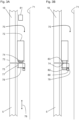
- the elevator system has a connecting device 70 by means of which the vertical guide rail piece 18 of the horizontal displacement unit 16 can be connected to the stationary vertical guide rail 5 when the horizontal displacement unit 16 is in the passage position.
- the connecting device 70 is arranged between the vertical guide rail piece 18 or the stationary vertical guide rail 5 and a shaft wall 71 .
- it is fastened to the rail feet of the two guide rails by fastening means (not shown).
- On the shaft wall 71 is fixed the stationary vertical guide rail 5 by means of an attitude, not shown.
- the connecting device 70 has a controllable actuator 72 in the form of an electric motor, which is arranged on an end 73 of the vertical guide rail piece 18 oriented in the direction of the stationary vertical rail 5 .
- the actuator 72 is controlled by the elevator control 36 (see Figure 1A ) is controlled and can extend a mainly cylindrical bolt 74 in an operating direction 76 running in the vertical direction into an extended position and retract it into a retracted position.
- the bolt 74 in the retracted position In the Figure 3A is the bolt 74 in the retracted position and in the Figure 3B shown in the extended position.
- a receptacle 77 is arranged on an end 75 of the stationary vertical guide rail 5 oriented in the direction of the vertical guide rail piece 18 .
- the receptacle 77 has a recess 78 in the form of a cylindrical through-opening oriented in the actuation direction 76 and thus vertically.
- An inner diameter of the recess 78 is slightly larger than an outer diameter of the bolt 74, so that the recess 78 can accommodate the bolt 74 with little play.
- the receptacle 77 and thus the recess 78 are arranged on the stationary vertical guide rail 5 in such a way that when the horizontal displacement unit 16 is in the passage position, the bolt 74 is inserted into the recess 78 when changing from the retracted position to the extended position, and thus as in FIG Figure 3B shown in the extended position in said recess 78 and creates a positive connection between vertical guide rail piece 18 and stationary vertical guide rail 5.
- the connecting device 70 is arranged in such a way that in this case the vertical guide rail piece 18 is aligned in relation to the stationary vertical guide rail 5 in such a way that there is no offset or step at the transition.
- a sensor device 79 with a safety switch 80 is arranged on the recess 78 on the side of the receptacle 77 opposite the actuator 72 .
- the safety switch 80 is actuated by the bolt 74 when it is in the extended position in the recess 78 .
- the sensor device 79 thus detects whether the vertical guide rail piece 18 is positively connected to the stationary vertical guide rail 5 and thus an elevator car 4 can be safely and comfortably moved out of or into the horizontal displacement unit 16 .
- the sensor device 79 is connected to a safety controller 81 by lines that are not shown.
- the safety controller 81 can be integrated into the elevator controller 36 or designed as a separate controller and connected to the elevator controller.
- the safety controller 81 is designed in such a way that it only allows an elevator car 4 to move vertically into the horizontal displacement unit 16 and out of the horizontal displacement unit 16 if the sensor device 79 detects that the vertical guide rail section 18 is connected to the stationary vertical guide rail 5 as described.
- the bolt 74 has an insertion bevel 82 in the direction of the recess 78, in which the outer diameter of the bolt 74 tapers slightly. In the area of the insertion bevel 82, the bolt 74 thus has a conical profile.
- a guide 83 is also arranged on the actuator 72, which guides the bolt 74 during a movement from the retracted position to the extended position and vice versa.
- the guide 83 has a in the Figures 3A, 3B not visible recess through which the bolt 74 protrudes.
- An inner contour of said recess corresponds to an outer contour of the bolt 74, as a result of which it cannot move transversely to the direction of actuation 76, or only very slightly.
Description
Die Erfindung betrifft ein Aufzugssystem gemäss dem Oberbegriff des Anspruchs 1.The invention relates to an elevator system according to the preamble of claim 1.
Die
Die Aufzugkabinen werden entlang einer Vertikalfahrbahn nur nach oben und entlang der anderen Vertikalfahrbahn nur nach unten verlagert. Um einen umlaufenden Betrieb der Aufzugkabinen realisieren zu können, können die Aufzugkabinen zwischen den beiden Vertikalfahrbahnen mittels Kabinentransfereinrichtungen horizontal verschoben werden. Im Betrieb des Aufzugsystems gemäss der
Eine Kabinentransfereinrichtung gemäss der
Die
Demgegenüber ist es insbesondere die Aufgabe der Erfindung, ein Aufzugsystem vorzuschlagen, welches einen besonders sicheren und komfortablen Schachtwechsel einer Aufzugskabine ermöglicht. Erfindungsgemäss wird diese Aufgabe mit einem Aufzugsystem mit den Merkmalen des Anspruchs 1 gelöst.In contrast, it is in particular the object of the invention to propose an elevator system which enables a particularly safe and comfortable shaft change of an elevator car. According to the invention, this object is achieved with an elevator system having the features of claim 1.
Das erfindungsgemässe Aufzugssystem weist wenigstens eine Aufzugskabine auf, welche in Vertikalfahrten entlang einer eine ortsfeste Vertikalführungsschiene umfassenden Vertikalfahrbahn und in Horizontalfahrten mittels einer Kabinentransfereinrichtung verfahrbar ist. Die Kabinentransfereinrichtung verfügt über eine Horizontalverschiebeeinheit mit einem vertikalen Führungsschienenstück, das die Aufzugskabine in der Horizontalverschiebeeinheit führt. Die Horizontalverschiebeeinheit ist in eine Durchfahrtposition bringbar, in welcher das Führungsschienenstück der Horizontalverschiebeeinheit mit der ortsfesten Vertikalführungsschiene einen Abschnitt der Vertikalfahrbahn bildet.The elevator system according to the invention has at least one elevator car, which can be moved in vertical travel along a vertical track comprising a stationary vertical guide rail and in horizontal travel by means of a car transfer device. The car transfer device has a horizontal displacement unit with a vertical guide rail piece that guides the elevator car in the horizontal displacement unit. The horizontal displacement unit can be brought into a drive-through position in which the guide rail section of the horizontal displacement unit forms a section of the vertical track with the stationary vertical guide rail.
Erfindungsgemäss weist das Antriebssystem eine Verbindungseinrichtung auf, mittels welcher in der Durchfahrtposition der Horizontalverschiebeeinheit das vertikale Führungsschienenstück der Horizontalverschiebeeinheit mit der ortsfesten Vertikalführungsschiene verbunden werden kann. Bei bestehender Verbindung des vertikalen Führungsschienenstücks mit der ortsfesten Vertikalführungsschiene mittels der Verbindungseinrichtung ist das vertikale Führungsschienenstück nicht in horizontaler Richtung gegenüber der ortfesten Vertikalführungsschiene verschiebbar.According to the invention, the drive system has a connecting device, by means of which the vertical guide rail piece of the horizontal displacement unit can be connected to the stationary vertical guide rail when the horizontal displacement unit is in the drive-through position. When the vertical guide rail piece is connected to the stationary vertical guide rail by means of the connecting device, the vertical guide rail piece cannot be displaced in the horizontal direction relative to the stationary vertical guide rail.
Die Aufzugskabine wird beim Verfahren bzw. Verlagern in bzw. entlang der Vertikalfahrbahn entlang der Vertikalführungsschienen geführt. Die Führungsschienen weisen insbesondere einen bekannten T-förmigen Querschnitt auf, wobei die so genannten Arme von einem Schienenfuss und der so genannte Stamm von einem Schienenkopf gebildet werden. Der Schienenkopf ist Richtung Aufzugskabine ausgerichtet und weist mindestens eine Lauffläche auf. Die Aufzugskabine weist insbesondere einen Läufer auf, der an der Lauffläche einer Führungsschiene entlanggleitet oder abrollt. Der Läufer kann beispielsweise in Form eines Führungsschuhs oder Führungsrollen ausgeführt sein. Eine Führungsschiene ist üblicherweise aus einzelnen Führungsschienenstücken zusammengesetzt, so dass insbesondere an den Übergängen von einem Führungsschienenstück zum nächsten Führungsschienenstück die Gefahr besteht, dass Führungsschienenstücke, insbesondere deren Laufflächen leicht versetzt zueinander angeordnet sind, es also zu einem so genannten Versatz kommt. Wenn der Läufer der Aufzugskabine über einen solchen Versatz gleitet oder rollt, so kann es zu einem spürbaren Ruck kommen, der Läufer beschädigt werden oder im schlimmsten Fall der Läufer aus der Führung springen. Diese Gefahr ist besonders gross beim Übergang eines horizontal verschiebbaren, vertikalen Führungsschienenstücks einer Horizontalverschiebeeinheit einer Kabinentransfereinrichtung auf eine ortsfeste Vertikalführungsschiene. Die mit der Verbindungseinrichtung hergestellte Verbindung des vertikalen Führungsschienenstücks der Horizontalverschiebeeinheit mit der ortsfesten Vertikalführungsschiene in der Durchfahrtposition der Horizontalverschiebeeinheit gewährleistet eine optimale Ausrichtung des vertikalen Führungsschienenstücks mit der ortsfesten Vertikalführungsschiene, so dass ein Übergang zwischen den beiden ohne einen Absatz oder einen Versatz sichergestellt werden kann. Das vertikale Führungsschienenstück und die ortsfeste Vertikalführungsschiene sind damit optimal zueinander ausgerichtet, so dass der Läufer der Aufzugskabine ohne Beeinträchtigungen oder Beschädigungen über den Übergang gleiten oder rollen kann. Dies ermöglicht einen besonders sicheren und komfortablen Betrieb des Aufzugssystems.The elevator car is guided along the vertical guide rails when moving or shifting in or along the vertical track. The guide rails have, in particular, a known T-shaped cross-section, the so-called arms being formed by a rail base and the so-called trunk being formed by a rail head. The rail head is aligned in the direction of the elevator car and has at least one running surface. In particular, the elevator car has a runner that slides or rolls along the running surface of a guide rail. The runner can be designed, for example, in the form of a guide shoe or guide rollers. A guide rail is usually composed of individual guide rail pieces, so that there is a risk, particularly at the transitions from one guide rail piece to the next guide rail piece, that guide rail pieces, in particular their running surfaces, are arranged slightly offset from one another, i.e. a so-called offset occurs. If the runner of the elevator car slides or rolls over such an offset, a noticeable jerk can occur, the runner can be damaged or, in the worst case, the runner can jump out of the guide. This risk is particularly great when a horizontally displaceable, vertical guide rail section of a horizontal displacement unit of a cabin transfer device transitions to a stationary vertical guide rail. The connection of the vertical guide rail piece of the horizontal displacement unit to the stationary vertical guide rail made with the connecting device in the passage position of the horizontal displacement unit ensures an optimal alignment of the vertical guide rail piece with the stationary vertical guide rail, so that a transition between the two can be ensured without a step or an offset. The vertical guide rail piece and the stationary vertical guide rail are thus optimally aligned with one another, so that the runner of the elevator car is not adversely affected or damage can slide or roll over the transition. This enables a particularly safe and comfortable operation of the elevator system.
Das Aufzugssystem verfügt insbesondere über mindestens zwei, nebeneinander angeordneten Vertikalfahrbahnen und mindestens zwei Kabinentransfereinrichtungen, die insbesondere am oberen und unteren Ende der Vertikalfahrbahnen angeordnet sind. Damit ist wie oben beschrieben ein umlaufender Betrieb der Aufzugskabinen möglich.The elevator system has in particular at least two vertical tracks arranged next to one another and at least two car transfer devices which are arranged in particular at the upper and lower end of the vertical tracks. As described above, a circulating operation of the elevator cars is thus possible.
Die Vertikalfahrbahnen und die Kabinentransfereinrichtungen sind insbesondere in einem oder in mehreren nebeneinanderliegenden Aufzugsschächten angeordnet, wobei die Vertikalfahrten hauptsächlich vertikal, also mit und gegen die Richtung der Schwerkraft, und die Horizontalfahrten hauptsächlich horizontal, also senkrecht zur Richtung der Schwerkraft verlaufen. Unter einer ortsfesten Vertikalführungsschiene soll hier eine unbewegliche, hauptsächlich vertikal ausgerichtete Führungsschiene verstanden werden. Die Vertikalführungsschiene ist insbesondere an einer Schachtwand des Aufzugsschachts fixiert, beispielsweise angeschraubt. Eine Vertikalfahrbahn weist insbesondere zwei sich gegenüberliegende Vertikalführungsschienen auf, zwischen welchen eine Aufzugskabine angeordnet sein kann.The vertical tracks and the car transfer devices are arranged in particular in one or in several adjacent elevator shafts, with the vertical movements being mainly vertical, i.e. with and against the direction of gravity, and the horizontal movements being mainly horizontal, i.e. perpendicular to the direction of gravity. A stationary vertical guide rail is to be understood here as meaning an immovable, mainly vertically aligned guide rail. The vertical guide rail is in particular fixed to a shaft wall of the elevator shaft, for example screwed on. A vertical track has, in particular, two opposite vertical guide rails, between which an elevator car can be arranged.
Die Vertikalfahrbahn ist insbesondere mit einem Kabinenantriebssystem ausgerüstet, das ein sich entlang der Vertikalfahrbahn bewegbares und anhaltbares flexibles Tragmittel umfasst. Die Aufzugskabine weist dann eine ansteuerbare Kopplungseinrichtung auf, mit welcher die Aufzugskabine an das Tragmittel angekoppelt und von diesem abgekoppelt werden kann.The vertical track is equipped in particular with a car drive system, which includes a flexible suspension element that can be moved and stopped along the vertical track. The elevator car then has a controllable coupling device with which the elevator car can be coupled to and decoupled from the suspension element.
Das Kabinenantriebssystem verfügt über mindestens eine ansteuerbare Antriebsmaschine, insbesondere einen Elektromotor, der das flexible Tragmittel bewegen und damit im Aufzugsschacht verlagern kann. Die Antriebsmaschine wird insbesondere von einer Aufzugsteuerung angesteuert. Die Aufzugsteuerung steuert den kompletten Betrieb des Aufzugssystems, sie steuert also alle ansteuerbaren Komponenten des Aufzugssystems an und ist mit Schaltern und Sensoren des Aufzugssystems verbunden. Die Aufzugsteuerung kann als eine einzige zentrale Aufzugsteuerung ausgeführt sein oder aus mehreren dezentralen Steuerungen bestehen, die für Teilaufgaben zuständig sind. Sie kann beispielsweise eine Sicherheitssteuerung aufweisen, welche den sicheren Betrieb des Aufzugsystems sicherstellt.The car drive system has at least one controllable drive machine, in particular an electric motor, which can move the flexible suspension element and thus shift it in the elevator shaft. The drive machine is controlled in particular by an elevator controller. The elevator controller controls the entire operation of the elevator system, so it controls all controllable components of the elevator system and is connected to switches and sensors of the elevator system. The elevator control can be designed as a single central elevator control or consist of several decentralized controls that are responsible for subtasks. For example, it can have a safety controller that ensures the safe operation of the Elevator system ensures.
Das Tragmittel ist insbesondere in sich geschlossen, also beispielsweise ringförmig ausgeführt. Es kann damit auch als endlos bezeichnet werden. Das bedeutet aber nicht zwingend, dass es als ein homogener Ring ausgeführt ist oder nur aus einem Stück besteht. Das Tragmittel ist insbesondere um eine untere und eine obere Umlenkrolle geführt, wobei mindestens eine Umlenkrolle als Antriebsrolle oder Treibscheibe dient, über die das Tragmittel von der ihm zugeordneten Antriebsmaschine angetrieben werden kann. Die Umlenkrollen weisen insbesondere einen Wirkdurchmesser von weniger als 100 mm auf. Derart geringe Wirkdurchmesser einer als Treibscheibe dienenden Umlenkrolle ermöglichen einen getriebelosen Antrieb des Tragmittels, der wenig Einbauraum beansprucht. Am Tragmittel kann insbesondere eine Spannvorrichtung angeordnet sein, mit welcher einerseits die erforderliche Tragmittelvorspannung erzeugt und andererseits Abweichungen in der ursprünglichen Länge des in sich geschlossenen Tragmittels sowie betriebsbedingte plastische Längenänderungen des Tragmittels ausgeglichen werden. Die erforderlichen Spannkräfte lassen sich beispielsweise mit Spanngewichten, Gasfedern oder Metallfedern erzeugen.The suspension element is in particular self-contained, that is, for example, designed in the shape of a ring. It can thus also be described as endless. However, this does not necessarily mean that it is designed as a homogeneous ring or consists of only one piece. The suspension element is in particular guided around a lower and an upper deflection roller, with at least one deflection roller serving as a drive roller or traction sheave, via which the suspension element can be driven by the drive machine assigned to it. In particular, the deflection rollers have an effective diameter of less than 100 mm. Such small effective diameters of a deflection pulley serving as a traction sheave enable a gearless drive of the suspension element, which requires little installation space. In particular, a tensioning device can be arranged on the suspension element, with which on the one hand the required suspension element pretension is generated and on the other hand deviations in the original length of the self-contained suspension element and operational plastic length changes of the suspension element are compensated for. The required tensioning forces can be generated, for example, with tensioning weights, gas springs or metal springs.
Die an der oder den Aufzugskabinen angeordneten Kopplungseinrichtungen sind insbesondere an einem Boden oder einem Dach der Aufzugskabinen angeordnet und werden von der oben genannten Aufzugsteuerung angesteuert. Die Ankopplung an ein Ankoppelelement des Tragmittels erfolgt insbesondere formschlüssig, wobei auch eine reibschlüssige Ankopplung denkbar ist. Das Ankoppelelement verfügt insbesondere über eine hauptsächlich horizontal orientierte Ausnehmung, in die beispielsweise in eine Betätigungsrichtung ein aus und einfahrbarer Bolzen der Kopplungseinrichtung eintauchen kann. Die Kopplungseinrichtung ist in diesem Fall in ihrer angekoppelten Position, wenn der Bolzen der Kopplungseinrichtung in die Ausnehmung des Ankoppelelements eintaucht und in ihrer abgekoppelten Position, wenn der Bolzen nicht in die Ausnehmung eintaucht bzw. die Ausnehmung frei bleibt.The coupling devices arranged on the elevator car(s) are arranged in particular on a floor or a roof of the elevator car and are controlled by the elevator control mentioned above. The coupling to a coupling element of the suspension element takes place in particular in a form-fitting manner, with a friction-fitting coupling also being conceivable. The coupling element has, in particular, a mainly horizontally oriented recess into which, for example, a bolt of the coupling device that can be moved in and out can enter in an actuation direction. In this case, the coupling device is in its coupled position when the bolt of the coupling device enters the recess of the coupling element and in its uncoupled position when the bolt does not enter the recess or the recess remains free.
Über die Kopplungseinrichtung und das Ankoppelelement kann damit eine form- oder reibschlüssige Verbindung zwischen der Aufzugskabine und dem Tragmittel hergestellt werden, so dass bei einer Verlagerung bzw. Bewegung des Treibmittels auch die Aufzugskabine verlagert wird. Damit ist eine Antriebsverbindung zwischen der Aufzugskabine und dem Tragmittel und damit letztlich zwischen der Aufzugkabine und der dem Tragmittel zugeordneten Antriebsmaschine herstellbar und auch wieder lösbar. Die Kopplungseinrichtungen werden insbesondere so angesteuert, dass zumindest während der Verlagerung einer Aufzugkabine an ein (einziges) Tragmittel nur eine Aufzugkabine angekoppelt ist. Von einem (einzigen) Tragmittel wird damit insbesondere immer nur eine (einzige) Aufzugkabine entlang der Vertikalfahrbahn verlagert.A positive or frictional connection between the elevator car and the suspension element can thus be produced via the coupling device and the coupling element, so that the elevator car is also displaced when the propellant is displaced or moved. This is a drive connection between the Elevator car and the support means and thus ultimately between the elevator car and the support means associated drive machine and also detachable again. The coupling devices are controlled in particular in such a way that, at least during the displacement of an elevator car, only one elevator car is coupled to a (single) suspension element. In particular, only one (single) elevator car is ever shifted along the vertical track by a (single) suspension element.
Ein Ankoppelelement eines Tragmittels ist insbesondere als ein Verbindungselement ausgeführt, welches zwei freie Enden des Tragmittels miteinander verbindet. Die Verwendung eines in sich geschlossenen Tragmittels ermöglicht den Verzicht auf ein Gegengewicht, das an der Aufzugkabine vorbeigeführt werden muss, was einen kleinen Querschnitt des Aufzugschachts ermöglicht. Ausserdem erfüllt das so ausgeführte Ankoppelelement eine Doppelfunktion. Es dient zum einen der Ankopplung der Aufzugkabine an das Tragmittel und zum anderen der einfachen und kostengünstigen Realisierung des geschlossenen Tragmittels.A coupling element of a suspension element is designed in particular as a connecting element which connects two free ends of the suspension element to one another. The use of a self-contained suspension means makes it possible to dispense with a counterweight that has to be guided past the elevator car, which allows for a small cross-section of the elevator shaft. In addition, the coupling element designed in this way fulfills a dual function. On the one hand, it serves to couple the elevator car to the suspension element and, on the other hand, to realize the closed suspension element in a simple and cost-effective manner.
Das Ankoppelelement erfüllt insbesondere die Funktion eines so genannten Riemenschlosses oder eines Seilverbinders. Damit kann sehr einfach, kostengünstig und sicher aus einem ursprünglich offenen, langgestreckten Tragmittel durch Verbinden der beiden freien Enden mit dem Ankoppelelement ein in sich geschlossenes Tragmittel hergestellt werden. Das Ankoppelelement kann beispielsweise zwei miteinander verbundene Tragmittelendverbindungen aufweisen, welche beispielsweise entsprechend der
Statt eines Kabinenantriebssystem mit einer Antriebsmaschine und einem Tragmittel kann das Aufzugsystem auch ein Kabinenantriebssystem ohne ein Tragmittel aufweisen. Das Kabinenantriebssystem kann beispielsweise als ein Antriebssystem mit einem Linearantrieb ausgeführt oder als ein Reibradantrieb ausgeführt sein. Derartige Kabinenantriebssysteme sind allgemein bekannt. Im Folgenden wird von einem Aufzugsystem mit einem Kabinenantriebssystem mit einer Antriebsmaschine und einem Tragmittel ausgegangen.Instead of a car drive system with a drive machine and a suspension element, the elevator system can also have a car drive system without a suspension element. The car drive system can be designed, for example, as a drive system with a linear drive or as a friction wheel drive. Such cabin drive systems are generally known. In the following, an elevator system with a car drive system with a drive machine and a suspension element is assumed.
Eine Horizontalverschiebeeinheit einer Kabinentransfereinrichtung weist insbesondere analog zu den ortsfesten Vertikalführungsschienen zwei sich gegenüberliegende vertikale Führungsschienenstücke auf. Das oder die Führungsschienenstücke werden bei einer Horizontalfahrt der Aufzugskabine horizontal verschoben. Während der Horizontalfahrt ist die Aufzugskabine temporär an dem oder den Führungsschienenstücken fixiert. Die Aufzugskabine weist dazu insbesondere eine Bremseinrichtung auf, mittels welcher sie sich an ein Führungsschienenstück festklemmen kann. Es ist auch möglich, dass die Horizontalverschiebeeinheit eine Fixierungseinrichtung aufweist, mittels welcher die Aufzugskabine während der Horizontalfahrt gehalten und damit zumindest mittelbar an einem Führungsschienenstück fixiert werden kann. Damit wird die Aufzugskabine während einer Horizontalfahrt geführt.A horizontal displacement unit of a cabin transfer device has, in particular analogously to the stationary vertical guide rails, two opposing vertical guide rail pieces. The guide rail piece or pieces are shifted horizontally when the elevator car travels horizontally. During horizontal travel, the elevator car is temporarily fixed to the guide rail piece or pieces. For this purpose, the elevator car has in particular a braking device, by means of which it can clamp itself to a piece of guide rail. It is also possible for the horizontal displacement unit to have a fixing device, by means of which the elevator car can be held during horizontal travel and thus at least indirectly fixed to a guide rail piece. The elevator car is thus guided during horizontal travel.
Die Horizontalverschiebeeinheit verfügt über einen Verschiebeantrieb mit einer Antriebseinheit, insbesondere in Form eines Elektromotors, mittels welchem das oder die vertikalen Führungsschienenstücke inklusive der Aufzugskabine horizontal verfahren werden können. Die Antriebseinheit wird ebenfalls von der oben genannten Aufzugsteuerung angesteuert.The horizontal displacement unit has a displacement drive with a drive unit, in particular in the form of an electric motor, by means of which the vertical guide rail piece or pieces, including the elevator car, can be moved horizontally. The drive unit is also controlled by the elevator control mentioned above.
Die Horizontalverschiebeeinheit und damit das oder die Führungsschienenstücke können in eine so genannte Durchfahrtposition gebracht werden. In der Durchfahrtposition sind das oder die vertikalen Führungsschienenstücke der Horizontalverschiebeeinheit und korrespondierende Vertikalführungsschienen so zueinander angeordnet bzw. ausgerichtet, dass ein Führungsschienenstück der Horizontalverschiebeeinheit mit der ortsfesten Vertikalführungsschiene einen Abschnitt der Vertikalfahrbahn bildet. In der genannten Durchfahrtposition kann damit eine Aufzugskabine in eine Horizontalverschiebeeinheit hinein oder aus ihr herausfahren.The horizontal displacement unit and thus the guide rail piece or pieces can be brought into a so-called drive-through position. In the drive-through position, the vertical guide rail piece(s) of the horizontal displacement unit and corresponding vertical guide rails are arranged or aligned with one another such that a guide rail piece of the horizontal displacement unit forms a section of the vertical track with the stationary vertical guide rail. In the passage position mentioned, an elevator car can thus move into or out of a horizontal displacement unit.
Bei einem Wechsel einer Aufzugskabine von einer ersten Vertikalfahrbahn zu einer zweiten Vertikalfahrbahn ist also die Horizontalverschiebeeinheit zunächst in einer ersten Durchfahrtposition, in der ihre vertikalen Führungsschienenstücke mit den ortsfesten Vertikalführungsschienen der ersten Vertikalfahrbahn einen Abschnitt der ersten Vertikalfahrbahn bilden. Die Führungsschienenstücke sind also so zu den korrespondierenden ortsfesten Vertikalführungsschienen ausgerichtet, dass die Aufzugskabine in die Horizontalverschiebeeinheit hineinfahren kann. Nach dem Hineinfahren wird die Aufzugskabine insbesondere mit einer Bremseinrichtung an den vertikalen Führungsschienenstücken fixiert. Anschliessend wird die Horizontalverschiebeeinheit und damit auch die Aufzugskabine horizontal bis zum Erreichen einer zweiten Durchfahrtposition verfahren. In der zweiten Durchfahrtposition bilden die vertikalen Führungsschienenstücke der Horizontalverschiebeeinheit mit den ortsfesten Vertikalführungsschienen der zweiten Vertikalfahrbahn einen Abschnitt der zweiten Vertikalfahrbahn. Damit kann die Aufzugskabine nach dem Lösen der Bremseinrichtung aus der Horizontalverschiebeeinheit herausfahren. Damit wird die Aufzugskabine von der oder den vertikalen Führungsschienenstücken auch beim Hineinfahren in die Horizontalverschiebeeinheit und beim Herausfahren aus der Horizontalverschiebeeinheit geführt.When an elevator car changes from a first vertical track to a second vertical track, the horizontal displacement unit is initially in a first passage position in which its vertical guide rail sections form a section of the first vertical track with the stationary vertical guide rails of the first vertical track. The guide rail pieces are so aligned to the corresponding stationary vertical guide rails that Elevator car can drive into the horizontal displacement unit. After entering, the elevator car is fixed in particular with a braking device on the vertical guide rail pieces. The horizontal displacement unit and thus also the elevator car are then moved horizontally until a second drive-through position is reached. In the second passage position, the vertical guide rail pieces of the horizontal displacement unit form a section of the second vertical track with the stationary vertical guide rails of the second vertical track. The elevator car can thus move out of the horizontal displacement unit after the braking device has been released. The elevator car is thus also guided by the vertical guide rail piece or pieces when driving into the horizontal displacement unit and when driving out of the horizontal displacement unit.
Beim beschriebenen Hinein und Herausfahren sind das oder die vertikalen Führungsschienenstücke der Horizontalverschiebeeinheit mittels einer Verbindungseinrichtung mit korrespondierenden ortsfesten Vertikalführungsschienen verbunden. Die Verbindung ist dabei so ausgeführt, dass ein Führungsschienenstück mit einer korrespondierenden Vertikalführungsschiene so zueinander ausgerichtet ist, dass möglichst kein Absatz oder Versatz vorhanden ist. Bei bestehender Verbindung kann das vertikale Führungsschienenstück nicht in horizontaler Richtung gegenüber der ortfesten Vertikalführungsschiene bewegt bzw. verschoben werden. Das vertikale Führungsschienenstück ist in diesem Fall damit gegenüber der ortfesten Vertikalführungsschiene in horizontaler Richtung unverschiebbar bzw. ortsfest oder unbeweglich angeordnet.When moving in and out as described, the vertical guide rail piece or pieces of the horizontal displacement unit are connected to corresponding stationary vertical guide rails by means of a connecting device. The connection is designed in such a way that a guide rail piece is aligned with a corresponding vertical guide rail in such a way that there is as little as possible a step or offset. With an existing connection, the vertical guide rail piece cannot be moved or shifted in the horizontal direction relative to the stationary vertical guide rail. In this case, the vertical guide rail piece is arranged so that it cannot be displaced or is stationary or immovable in the horizontal direction relative to the stationary vertical guide rail.
Die Verbindungseinrichtung ist insbesondere in einem Bereich zwischen den vertikalen Führungsschienen und einer Schachtwand, an der die ortsfeste Vertikalführungsschiene befestigt ist, angeordnet. Bei Führungsschienen mit einem T-förmigen Querschnitt ist die Verbindungseinrichtung damit insbesondere am Schienenfuss der Führungsschienen angeordnet.The connecting device is arranged in particular in an area between the vertical guide rails and a shaft wall to which the stationary vertical guide rail is fastened. In the case of guide rails with a T-shaped cross section, the connecting device is therefore arranged in particular on the rail base of the guide rails.
In Ausgestaltung der Erfindung ist die Verbindungseinrichtung so ausgeführt und angeordnet, dass das vertikale Führungsschienenstück der Horizontalverschiebeeinheit formschlüssig mit der ortsfesten Vertikalführungsschiene verbunden werden kann. Damit wird eine besonders sichere Verbindung ermöglicht. Ausserdem können damit die Führungsschienen sehr genau zueinander ausgerichtet werden.In an embodiment of the invention, the connecting device is designed and arranged in such a way that the vertical guide rail piece of the horizontal displacement unit can be positively connected to the stationary vertical guide rail. With it a particularly secure connection is made possible. In addition, the guide rails can be aligned very precisely with one another.
In Ausgestaltung der Erfindung weist die Verbindungseinrichtung einen ansteuerbaren Aktor auf, welcher am vertikalen Führungsschienenstück der Horizontalverschiebeeinheit angeordnet ist. Der Aktor wird also zusammen mit dem vertikalen Führungsschienenstück verschoben. Damit ist für alle Vertikalfahrbahnen nur ein Aktor pro vertikalem Führungsschienenstück notwendig. Wenn der Aktor an der ortsfesten Vertikalführungsschiene einer Vertikalfahrbahn angeordnet wäre, wären für jedes vertikale Führungsschienenstück mehrere Aktoren notwendig, nämlich pro Vertikalfahrbahn ein Aktor.In an embodiment of the invention, the connecting device has a controllable actuator which is arranged on the vertical guide rail piece of the horizontal displacement unit. The actuator is thus moved together with the vertical guide rail piece. This means that only one actuator per vertical guide rail section is required for all vertical tracks. If the actuator were arranged on the stationary vertical guide rail of a vertical track, several actuators would be necessary for each vertical guide rail piece, namely one actuator per vertical track.
Der Aktor ist insbesondere als ein Elektromotor ausgeführt. Er kann aber auch beispielsweise als ein pneumatischer oder hydraulischer Aktor ausgeführt sein. Der Aktor wird insbesondere ebenfalls von der oben genannten Aufzugsteuerung angesteuert.The actuator is designed in particular as an electric motor. However, it can also be designed, for example, as a pneumatic or hydraulic actuator. The actuator is in particular also controlled by the elevator controller mentioned above.
In Ausgestaltung der Erfindung weist die Verbindungseinrichtung einen Bolzen auf, welcher eine zurückgezogene Position und eine ausgefahrene Position einnehmen kann. Die Verbindungseinrichtung verfügt ausserdem über eine mit dem Bolzen korrespondierende Ausnehmung, welche so ausgeführt und angeordnet sind, dass in der Durchfahrtposition der Horizontalverschiebeeinheit der Bolzen in der ausgefahrenen Position in die genannte Ausnehmung eintaucht und damit das vertikale Führungsschienenstück der Horizontalverschiebeeinheit formschlüssig mit der ortsfesten Vertikalführungsschiene verbunden ist und der Bolzen in der zurückgezogenen Position von der genannten Ausnehmung beabstandet ist und damit das vertikale Führungsschienenstück der Horizontalverschiebeeinheit gegenüber der ortsfesten Vertikalführungsschiene horizontal verschiebbar ist. Damit kann auf einfache und kostengünstige Weise eine formschlüssige Verbindung zwischen einem vertikalen Führungsschienenstück und einer korrespondierenden Vertikalführungsschiene hergestellt werden.In an embodiment of the invention, the connecting device has a bolt which can assume a retracted position and an extended position. The connecting device also has a recess corresponding to the bolt, which is designed and arranged in such a way that when the horizontal displacement unit is in the drive-through position, the bolt in the extended position dips into the said recess and the vertical guide rail section of the horizontal displacement unit is thus positively connected to the stationary vertical guide rail and the bolt is spaced from said recess in the retracted position and thus the vertical guide rail section of the horizontal displacement unit is horizontally displaceable with respect to the stationary vertical guide rail. A form-fitting connection between a vertical guide rail piece and a corresponding vertical guide rail can thus be produced in a simple and cost-effective manner.
Der Bolzen ist insbesondere am vertikalen Führungsschienenstück angeordnet und wird von einem am vertikalen Führungsschienenstück angeordneten Aktor in einer Betätigungsrichtung betätigt, also ein- und ausgefahren. Hier verläuft die genannte Betätigungsrichtung hauptsächlich vertikal. Unter einer "mit dem Bolzen korrespondierende Ausnehmung" soll hier eine Ausnehmung verstanden werden, die eine so an den Bolzen angepasste Form aufweist, dass bei in die Ausnehmung eingetauchtem Bolzen nur eine minimale Relativbewegung quer zur Betätigungsrichtung des Bolzens, also horizontal möglich ist.The bolt is arranged in particular on the vertical guide rail piece and is actuated in an actuating direction by an actuator arranged on the vertical guide rail piece, that is to say moved in and out. Here goes the mentioned Actuation direction mainly vertical. A "recess corresponding to the bolt" is to be understood here as a recess which has a shape adapted to the bolt such that when the bolt is immersed in the recess, only minimal relative movement transverse to the direction of actuation of the bolt, i.e. horizontally, is possible.
In Ausgestaltung der Erfindung weist der Bolzen in Richtung Ausnehmung eine Einführschräge auf. Damit kann der Bolzen zuverlässig in die Ausnehmung eingeführt werden. Insbesondere auch dann, wenn die Horizontalverschiebeeinheit nicht ganz exakt in die Durchfahrtposition gefahren, das vertikale Führungsschienenstück also noch nicht exakt gegenüber der ortsfesten Vertikalführungsschiene positioniert ist. Durch die Einführschräge kann auch in diesem Fall der Bolzen in die Ausnehmung eingeführt werden und dabei die Horizontalverschiebeeinheit entsprechend verschoben werden. Damit können beispielsweise Ungenauigkeiten in der Positionierung der Horizontalverschiebeeinheit im Bereich von einigen Millimetern, beispielsweise 2 - 3 mm ausgeglichen werden.In an embodiment of the invention, the bolt has an insertion bevel in the direction of the recess. The bolt can thus be reliably inserted into the recess. In particular, when the horizontal displacement unit is not exactly moved into the drive-through position, ie the vertical guide rail piece is not yet exactly positioned in relation to the stationary vertical guide rail. In this case, too, the bolt can be inserted into the recess through the insertion bevel and the horizontal displacement unit can be displaced accordingly. In this way, for example, inaccuracies in the positioning of the horizontal displacement unit in the range of a few millimeters, for example 2-3 mm, can be compensated.
Unter einer Einführschräge soll hier eine Verjüngung eines Querschnitts des Bolzens in Richtung Ausnehmung verstanden werden. Bei einem zylinderförmigen Bolzen nimmt damit der Durchmesser des Bolzens in der Einführschräge ab, so dass ein konusförmiger Verlauf entsteht.An insertion slope is to be understood here as a narrowing of a cross section of the bolt in the direction of the recess. In the case of a cylindrical bolt, the diameter of the bolt decreases in the insertion bevel, resulting in a cone-shaped course.
In Ausgestaltung der Erfindung weist die Verbindungseinrichtung eine Führung auf, welche den Bolzen bei einer Bewegung von der zurückgezogenen Position in die ausgefahrene Position und umgekehrt führt. Die Führung gewährleistet zum einen, dass der Bolzen sicher in die Ausnehmung eingeführt werden kann und zum anderen, dass sich der Bolzen sehr genau eine vorgesehene Bewegung ausführt.In an embodiment of the invention, the connecting device has a guide which guides the bolt during a movement from the retracted position to the extended position and vice versa. The guide ensures, on the one hand, that the bolt can be safely inserted into the recess and, on the other hand, that the bolt executes an intended movement very precisely.
Die Führung sorgt insbesondere dafür, dass der Bolzen nicht quer zur Betätigungsrichtung, also in horizontaler Richtung ausweichen kann. Damit wird eine besonders genaue Ausrichtung des vertikalen Führungsschienenstücks gegenüber der ortsfesten Vertikalführungsschiene erreicht. Die Führung ist insbesondere am vertikalen Führungsschienenstück angeordnet. Sie ist beispielsweise als ein Blech mit einer Ausnehmung ausgeführt, durch welche der Bolzen durchragt.In particular, the guide ensures that the bolt cannot deflect transversely to the direction of actuation, ie in the horizontal direction. This achieves a particularly precise alignment of the vertical guide rail piece with respect to the stationary vertical guide rail. The guide is arranged in particular on the vertical guide rail piece. It is designed, for example, as a metal sheet with a recess through which the bolt protrudes.
In Ausgestaltung der Erfindung weist das Aufzugssystem eine Sensoreinrichtung auf, mittels welcher erfassbar ist, ob das vertikale Führungsschienenstück der Horizontalverschiebeeinheit mit der ortsfesten Vertikalführungsschiene verbunden ist. Die von der Sensoreinrichtung erfasste Information kann vorteilhafterweise für einen besonders sicheren Betrieb des Aufzugssystems verwendet werden.In an embodiment of the invention, the elevator system has a sensor device, by means of which it can be detected whether the vertical guide rail section of the horizontal displacement unit is connected to the stationary vertical guide rail. The information recorded by the sensor device can advantageously be used for a particularly safe operation of the elevator system.
Die Sensoreinrichtung weist insbesondere einen an der Ausnehmung der Verbindungseinrichtung angeordneten Schalter auf, welcher vom Bolzen der Verbindungseinrichtung in der ausgefahrenen Position betätigt wird und in der zurückgezogenen Position des Bolzens unbetätigt ist. Damit kann sehr einfach und kostengünstig und gleichzeitig sicher erkannt werden, ob das vertikale Führungsschienenstück der Horizontalverschiebeeinheit mit der ortsfesten Vertikalführungsschiene verbunden ist.The sensor device has, in particular, a switch arranged on the recess of the connecting device, which is actuated by the bolt of the connecting device in the extended position and is not actuated in the retracted position of the bolt. In this way, it can be detected very easily and inexpensively and at the same time reliably whether the vertical guide rail section of the horizontal displacement unit is connected to the stationary vertical guide rail.
In Ausgestaltung der Erfindung weist das Aufzugssystem eine Sicherheitssteuerung auf, welche mit der genannten Sensoreinrichtung verbunden und dazu vorgesehen ist, ein vertikales Verfahren der Aufzugskabine in die Horizontalverschiebeeinheit und aus der Horizontalverschiebeeinheit heraus nur zuzulassen, wenn mit der genannten Sensoreinrichtung erfasst wird, dass das vertikale Führungsschienenstück der Horizontalverschiebeeinheit mit der ortsfesten Vertikalführungsschiene verbunden ist. Damit wird sichergestellt, dass die Aufzugskabine nur dann in die Horizontalverschiebeeinheit hinein oder aus ihr herausgefahren wird, wenn das vertikale Führungsschienenstück und die ortsfeste Vertikalführungsschiene miteinander verbunden und damit korrekt zueinander ausgerichtet sind. Damit wird ein besonders sicherer Betrieb des Aufzugssystems gewährleistet.In an embodiment of the invention, the elevator system has a safety controller which is connected to the named sensor device and is intended to only allow the elevator car to move vertically into the horizontal displacement unit and out of the horizontal displacement unit if the named sensor device detects that the vertical guide rail piece the horizontal displacement unit is connected to the stationary vertical guide rail. This ensures that the elevator car is only moved into or out of the horizontal displacement unit when the vertical guide rail piece and the stationary vertical guide rail are connected to one another and are therefore correctly aligned with one another. This ensures a particularly safe operation of the elevator system.
Die Sicherheitssteuerung kann als ein Teil der genannten Aufzugsteuerung oder als eine separate Steuerungseinrichtung ausgeführt sein. Sie kann in einen so genannten und an sich bekannten Sicherheitskreis des Aufzugssystems eingebunden sein.The safety control can be implemented as a part of said elevator control or as a separate control device. It can be integrated into a so-called safety circuit of the elevator system, which is known per se.
In Ausgestaltung der Erfindung weist die Kabinentransfereinrichtung einen Verschiebeantrieb mit einer Antriebseinheit und einem Verschieberiemen auf. Die Horizontalverschiebeeinheit ist dabei mittels des Verschiebeantriebs horizontal verschiebbar. Eine Antriebsverbindung zwischen Antriebseinheit des Verschiebeantriebs und Horizontalverschiebeeinheit ist mittels des als Zahnriemen ausgeführten Verschieberiemens hergestellt. Die Ausführung des Verschieberiemens als Zahnriemen gewährleistet eine formschlüssige und damit schlupffreie Antriebsverbindung zwischen Antriebseinheit und Horizontalverschiebeeinheit. Damit kann aus den Bewegungen, beispielsweise Drehungen einer Antriebsachse der Antriebseinheit sicher auf die horizontale Position der Horizontalverschiebeeinheit geschlossen werden. Damit kann die horizontale Position der Horizontalverschiebeeinheit mittels einer Steuerung eingestellt werden. Dies ermöglicht eine kostengünstige Ausführung des Verschiebeantriebs.In an embodiment of the invention, the cabin transfer device has a displacement drive with a drive unit and a displacement belt. The horizontal displacement unit is horizontal by means of the displacement drive movable. A drive connection between the drive unit of the displacement drive and the horizontal displacement unit is established by means of the displacement belt designed as a toothed belt. The design of the shifting belt as a toothed belt ensures a form-fitting and therefore non-slip drive connection between the drive unit and the horizontal shifting unit. The horizontal position of the horizontal displacement unit can thus be reliably inferred from the movements, for example rotations, of a drive axle of the drive unit. The horizontal position of the horizontal displacement unit can thus be adjusted by means of a controller. This enables a cost-effective design of the displacement drive.
Zähne des Zahnriemens bestehen insbesondere aus einem Elastomer, wobei die Kraft im Zahnriemen durch einen steifen Zugstrang übertragen wird, der beispielsweise aus Glas oder Aramidfasern besteht. Der Verschiebeantrieb kann auch über zwei oder mehr, hintereinander geschaltete Verschieberiemen verfügen, wobei dann insbesondere alle Verschieberiemen als Zahnriemen ausgeführt sind.Teeth of the toothed belt consist in particular of an elastomer, with the force in the toothed belt being transmitted by a stiff tension cord which consists, for example, of glass or aramid fibers. The displacement drive can also have two or more displacement belts connected in series, in which case in particular all displacement belts are designed as toothed belts.
In Ausgestaltung der Erfindung weist die Kabinentransfereinrichtung eine Positionserfassungseinrichtung auf, mittels welcher eine horizontale Position der Horizontalverschiebeeinheit innerhalb der Kabinentransfereinrichtung erfassbar ist. Damit ist die horizontale Position der Horizontalverschiebeeinheit und damit auch die horizontale Position des oder der vertikalen Führungsschienenstücke der Horizontalverschiebeeinheit besonders genau einstellbar. Die genannte Position kann damit insbesondere mittels einer Regelung eingestellt werden.In an embodiment of the invention, the cabin transfer device has a position detection device, by means of which a horizontal position of the horizontal displacement unit within the cabin transfer device can be detected. The horizontal position of the horizontal displacement unit and thus also the horizontal position of the vertical guide rail piece(s) of the horizontal displacement unit can thus be set particularly precisely. The stated position can thus be set, in particular, by means of a regulation.
Die Positionserfassungseinrichtung kann einen oder mehrere Positionssensoren aufweisen. Sie kann auch als eine so genannte kontinuierliche Positionsmesseinrichtung, beispielsweise in Form eines Zugseilsensors ausgeführt sein. Die Positionserfassungseinrichtung kann beispielsweise auch als eine so genannte Absolut-Positionserfassungseinrichtung ausgeführt sein, welche aus erfassten Markierungen an der Kabinentransfereinrichtung die horizontale Position der Horizontalverschiebeeinheit bestimmt. Die genannten Markierungen können beispielsweise an einem so genannten Längsträger der Kabinentransfereinrichtung angeordnet sein und mittels einer Kamera erfasst werden. Derartige Absolut-Positionserfassungseinrichtungen sind in unterschiedlichen Ausführungen auf dem Markt erhältlich.The position detection device can have one or more position sensors. It can also be designed as a so-called continuous position measuring device, for example in the form of a cable sensor. The position detection device can also be designed, for example, as a so-called absolute position detection device, which determines the horizontal position of the horizontal displacement unit from detected markings on the cabin transfer device. Said markings can be arranged, for example, on what is known as a longitudinal beam of the cabin transfer device and can be captured by a camera. Such absolute position detection devices are available in different designs on the market.
Weitere Vorteile, Merkmale und Einzelheiten der Erfindung ergeben sich anhand der nachfolgenden Beschreibung von Ausführungsbeispielen sowie anhand der Zeichnungen, in welchen gleiche oder funktionsgleiche Elemente mit identischen Bezugszeichen versehen sind. Die Zeichnungen sind lediglich schematisch und nicht massstabsgetreu.Further advantages, features and details of the invention result from the following description of exemplary embodiments and from the drawings, in which identical or functionally identical elements are provided with identical reference symbols. The drawings are merely schematic and not true to scale.
Dabei zeigen:
- Fig. 1A
- eine Frontansicht eines Aufzugssystems mit zwei Vertikalfahrbahnen, zwei Aufzugskabinen und zwei Kabinentransfereinrichtungen,
- Fig. 1B
- eine Seitenansicht des Aufzugssystems gemäss
Fig. 1A , - Fig. 2A
- eine Horizontalverschiebeeinheit der genannten Kabinentransfereinrichtungen in einer Seitenansicht,
- Fig. 2B
- eine Frontansicht der Horizontalverschiebeeinheit gemäss
Fig. 2A , - Fig. 3A
- eine Verbindungseinrichtung zum Verbinden eines vertikalen Führungsschienenstücks mit einer ortsfesten Vertikalführungsschiene in einem unverbundenen Zustand und
- Fig. 3B
- die Verbindungseinrichtung aus
Fig. 3A in einem verbundenen Zustand.
- Figure 1A
- a front view of an elevator system with two vertical tracks, two elevator cars and two car transfer devices,
- Figure 1B
- a side view of the elevator system according to FIG
Figure 1A , - Figure 2A
- a side view of a horizontal displacement unit of said cabin transfer devices,
- Figure 2B
- according to a front view of the horizontal displacement unit
Figure 2A , - Figure 3A
- a connecting device for connecting a vertical guide rail piece to a stationary vertical guide rail in an unconnected state and
- Figure 3B
- the connection device
Figure 3A in a connected state.
Gemäss
Als Variante kann jede Aufzugskabine auch nur eine einzige Kopplungseinrichtung aufweisen, die unbeweglich sein kann oder jeweils vor dem Ankoppeln durch eine gesteuerte Positioniervorrichtung in eine mit dem momentan zugeordneten Kabinenantriebssystem korrespondierende Position gebracht wird.As a variant, each elevator car can also have only a single coupling device, which can be stationary or, prior to being coupled, by a positioning device controlled into one with the one currently associated Car drive system corresponding position is brought.
Die Vertikalfahrbahnen 3 sind parallel zu Kabinentüren 10 aufweisenden Kabinenwänden 11 gegeneinander versetzt. Sie angeordnet. Die Vertikalfahrbahnen können auch rechtwinklig zu den die Kabinentüren aufweisenden Kabinenwänden gegeneinander versetzt angeordnet sein.The vertical tracks 3 are offset from one another parallel to the
Im Normalbetrieb dient eine der Vertikalfahrbahnen 3 als Fahrbahn für die Aufwärtsfahrt und die andere als Fahrbahn für die Abwärtsfahrt der Aufzugskabinen 4, wobei jede der Aufzugskabinen 4 nach dem Erreichen eines Stockwerkniveaus im Endbereich einer Vertikalfahrbahn 3 einen Horizontaltransfer zur andern Vertikalfahrbahn 3 ausführt, auf der sich die Aufzugskabine 4 in umgekehrter Fahrrichtung weiterbewegen kann.In normal operation, one of the vertical tracks 3 serves as a track for the ascent and the other as a track for the descent of the
Jeweils in Bereichen von Stockwerkshaltestellen 12 sind drei Kabinentransfereinrichtungen 13 dargestellt, mit deren Hilfe die Aufzugskabinen 4 zwischen den Vertikalfahrbahnen 3 verschiebbar sind. Jede der Kabinentransfereinrichtungen 13 umfasst zwei an einer türseitigen Wand des Aufzugsschachts 2 fixierte Horizontalführungen 14, 15 und eine entlang dieser Horizontalführungen 14, 15 verschiebbare Horizontalverschiebeeinheit 16. Eine solche Horizontalverschiebeeinheit 16 umfasst eine Rahmenkonstruktion 17, in der zwei vertikale Führungsschienenstücke 18 fixiert sind, welche Endabschnitte oder Zwischenabschnitte der Vertikalführungsschienen 5 der Vertikalfahrbahnen 3 bilden, wenn die Horizontalverschiebeeinheit 16 in einer entsprechenden Durchfahrtsposition positioniert ist. Die Rahmenkonstruktion 17 ist so gestaltet, dass die Aufzugskabinen 4 in Vertikalrichtung durch die in korrekter Durchfahrtsposition stehende Horizontalverschiebeeinheit 16 hindurchfahren oder in dieser anhalten können, wobei die Aufzugskabinen an den genannten Führungsschienenstücken 18 geführt sind.Three
Die Kabinentransfereinrichtungen 13 sind mit jeweils einem hier nicht dargestellten Verschiebeantrieb (24 in
Auf beiden Seiten der Aufzugskabinen 4 sind steuerbare Bremseinrichtungen 20 angebracht, die so mit den Vertikalführungsschienen 5 und den vertikalen Führungsschienenstücken 18 der Horizontalverschiebeeinheiten 16 zusammenwirken, dass die Bremseinrichtungen 20 die Aufzugskabinen 4 abbremsen bzw. festhalten, wenn sie beispielsweise durch die Aufzugsteuerung 36 aktiviert sind. Mit diesen Bremseinrichtungen 20 werden die Aufzugskabinen 4 an den in den Horizontalverschiebeeinheiten 16 integrierten Führungsschienenstücken 18 festgehalten, während sie zwischen zwei Vertikalfahrbahnen 3 verschoben werden. Dieselben Bremseinrichtungen 20 können auch als Fangvorrichtungen benutzt werden, welche im Fall eine Überschreitung der zulässigen Kabinengeschwindigkeit oder der Beschleunigung als zwischen Aufzugskabinen 4 und Vertikalführungsschienen 5 wirkende Sicherheitsbremsen wirken. Dieselben Bremseinrichtungen 20 können ausserdem als Haltebremsen dienen, die während Stockwerkshalten Vertikalschwingungen sowie Niveauänderungen der Aufzugskabinen 4 infolge von Laständerungen verhindern. Die Bremseinrichtungen 20 enthalten üblicherweise Bremsplatten, die durch steuerbare Aktuatoren gegen die Vertikalführungsschienen 5 gepresst werden. Für die Realisierung solcher Aktuatoren kommen verschiedene Prinzipien in Frage, beispielsweise Hubspindeln mit drehmomentregelbaren Antriebsmotoren, Hydraulikzylinder mit Druckregelung, oder Elektromagnete, die sich im aktivierten Zustand an die Führungsschienen heften. Die erzeugte Bremskraft wird dabei vorzugsweise in Abhängigkeit von der durch einen Verzögerungssensor gemessenen Verzögerung der Aufzugskabine 4 geregelt.
Es ist leicht erkennbar, dass bei der in
Da in den Bereichen der Kabinentransfereinrichtungen 13 die Vertikalführungsschienen 5 der Vertikalfahrbahnen 3 unterbrochen sind, sorgt die Aufzugsteuerung 36 dafür, dass vor jeder Einfahrt einer Aufzugkabine in einen solchen Bereich eine Horizontalverschiebeeinheit 16 mit ihren Führungsschienenstücken 18 die Unterbrechungen überbrückt. Steht für eine erforderliche Überbrückung keine Horizontalverschiebeeinheit rechtzeitig zur Verfügung, wird die Aufzugkabine 4 vor dem Erreichen des unterbrochenen Bereichs gestoppt.Since the
Der Verschiebeantrieb 24 ist oberhalb der Horizontalverschiebeeinheit 16 angeordnet und umfasst einen auf der oberen Horizontalführung 14 befestigten, sich über die gesamte Verschiebedistanz erstreckenden Riementrieb mit einer Antriebseinheit 32, einem umlaufendem Verschieberiemen in Form eines Zahnriemens 33 und einer Umlenkriemenscheibe 34, wobei das untere Trum des Zahnriemens mit dem oberen Längsträger 27 der Horizontalverschiebeeinheit 16 verbunden ist.The
Die Steuerung der Antriebseinheiten 32 der Horizontalverschiebeeinheiten 16 erfolgt vorzugsweise durch die Aufzugsteuerung 36 (siehe
Die Kabinentransfereinrichtung 13 weist eine Positionserfassungseinrichtung 35 auf, mittels welcher die horizontale Position der Horizontalverschiebeeinheit 16 innerhalb der Kabinentransfereinrichtung 13 erfassbar ist. Die Positionserfassungseinrichtung 35 ist am oberen Längsträger 27 der Horizontalverschiebeeinheit 16 angeordnet und erfasst nicht dargestellte Markierungen auf der oberen Horizontalführung 14. Aus den erfassten Markierungen kann die Positionserfassungseinrichtung 35 auf die horizontale Position der Horizontalverschiebeeinheit 16 schliessen. Damit kann die horizontale Position sehr genau, insbesondere mittels einer Regelung eingestellt werden.The
Zum Bewegen und Positionieren der Aufzugskabinen 4 entlang ihrer Vertikalfahrbahnen 3 sind jeder Vertikalfahrbahn 3 unabhängig voneinander steuerbare Kabinenantriebssysteme 7 zugeordnet. Diese Kabinenantriebssysteme 7 ermöglichen ein asynchrones, d. h. nicht gekoppeltes Bewegen von mehreren Aufzugskabinen 4 auf derselben Vertikalfahrbahn 3. Zu diesem Zweck sind die Aufzugskabinen 4 mit Hilfe von steuerbaren Kopplungseinrichtungen 40 an flexible Tragmittel eines Kabinenantriebssystems ankoppelbar, die den Aufzugkabinen 4 durch die Aufzugsteuerung 36 temporär zugeordnet sind. Das Aufzugssystem kann auch mit mehr oder mit weniger als drei voneinander unabhängigen Kabinenantriebssystemen ausgestattet sein.For moving and positioning the
Jedes der dargestellten Kabinenantriebssysteme 7 umfasst mindestens ein, entlang der zugeordneten Vertikalfahrbahnen 3 bewegbares, flexibles Tragmittel 8, das vorzugsweise im oberen Aufzugsbereich eine Treibscheibe 41 und im unteren Bereich eine Umlenkscheibe 42 oder eine zweite Treibscheibe umschlingt. Jede Treibscheibe 41 wird durch eine Antriebseinheit 43 angetrieben, die vorzugsweise einen drehzahlregelbaren Elektromotor umfasst. Die jeweils einem der Kabinenantriebssysteme 7 zugeordneten Antriebseinheiten 43 bzw. deren Elektromotoren sind unabhängig von den andern, derselben Vertikalfahrbahn 3 zugehörigen Antriebseinheiten 43 steuerbar und regelbar. Die Treibscheiben 41 weisen einen geringen Wirkdurchmesser von weniger als 100 mm, vorzugsweise einen Wirkdurchmesser von weniger als 80 mm, auf. Dabei können die Motorwellen der Elektromotoren und die zugehörigen Treibscheiben eine einstückige Einheit bilden. Die zulässige Belastung eines Kabinenantriebssystems kann erhöht werden, indem jeweils einem Kabinenantriebssystem eine obere und eine untere Antriebseinheit mit je einer Treibscheibe zugeordnet werden. Eine solche Ausführungsform ist in den
Die Treib- oder Umlenkscheiben im unteren Aufzugsbereich sind hier mit durch Pfeile P symbolisch dargestellten Spannvorrichtungen ausgerüstet, mit welchen einerseits die erforderliche Tragmittelvorspannung erzeugt und andererseits Abweichungen in den ursprünglichen Längen der in sich geschlossenen Tragmittel sowie betriebsbedingte plastische Längenänderungen in den Tragmitteln ausgeglichen werden. Die erforderlichen Spannkräfte lassen sich vorzugsweise mit Spanngewichten, Gasfedern oder Metallfedern erzeugen.The traction or deflection sheaves in the lower elevator area are equipped with tensioning devices symbolically represented by arrows P, with which on the one hand the necessary suspension element pretension is generated and on the other hand deviations in the original lengths of the self-contained suspension elements as well as operational plastic length changes in the suspension elements are compensated for. The required clamping forces can preferably be generated with clamping weights, gas springs or metal springs.
Die in den Aufzugssystemen gemäss
Wie vorstehend bereits erwähnt, ist jede Aufzugskabine 4 des dargestellten Aufzugssystems mit steuerbaren Kopplungseinrichtungen 40 ausgerüstet, die das Ankoppeln von jeweils einer Aufzugskabine 4 an ein temporär zugeordnetes Kabinenantriebssystem 7 und selbstverständlich auch das Abkoppeln von diesem ermöglichen. Eine solche Kopplungseinrichtung 40 weist mindestens ein steuerbar bewegliches Kopplungselement auf, das mit an dem mindestens einen Tragmittel des zugeordneten Kabinenantriebssystems vorhandenen Öffnungen oder Nocken formschlüssig zusammenwirkt, um eine temporäre Verbindung zwischen einer Aufzugskabine und dem Tragmittel zu erzeugen.As already mentioned above, each
Wie in den
Die Verbindungseinrichtung 70 verfügt über einen ansteuerbaren Aktor 72 in Form eines Elektromotors, welcher an einem in Richtung ortsfeste Vertikalschiene 5 orientierten Ende 73 des vertikalen Führungsschienenstücks 18 angeordnet ist. Der Aktor 72 wird von der Aufzugsteuerung 36 (siehe
An einem in Richtung vertikalen Führungsschienenstück 18 orientierten Ende 75 der ortsfesten Vertikalführungsschiene 5 ist eine Aufnahme 77 angeordnet. Die Aufnahme 77 weist eine Ausnehmung 78 in Form einer zylinderförmigen, in Betätigungsrichtung 76 und damit vertikal ausgerichteten Durchgangsöffnung auf. Ein Innendurchmesser der Ausnehmung 78 ist ein wenig grösser als ein Aussendurchmesser des Bolzens 74, so dass die Ausnehmung 78 den Bolzen 74 mit wenig Spiel aufnehmen kann. Die Aufnahme 77 und damit die Ausnehmung 78 sind so an der ortsfesten Vertikalführungsschiene 5 angeordnet, dass in der Durchfahrtposition der Horizontalverschiebeeinheit 16 der Bolzen 74 beim Wechsel von der zurückgezogenen Position in die ausgefahrene Position in die Ausnehmung 78 eingeführt wird und damit wie in
In der in der
An der dem Aktor 72 gegenüberliegenden Seite der Aufnahme 77 ist an der Ausnehmung 78 eine Sensoreinrichtung 79 mit einem Sicherheitsschalter 80 angeordnet. Der Sicherheitsschalter 80 wird vom Bolzen 74 betätigt, wenn dieser in der Ausnehmung 78 die ausgefahrene Position einnimmt. Die Sensoreinrichtung 79 erfasst also, ob das vertikale Führungsschienenstück 18 formschlüssig mit der ortsfesten Vertikalführungsschiene 5 verbunden ist und damit eine Aufzugskabine 4 sicher und komfortabel aus der Horizontalverschiebeeinheit 16 heraus oder in sie hineingefahren werden kann. Die Sensoreinrichtung 79 ist mit nicht dargestellten Leitungen mit einer Sicherheitssteuerung 81 verbunden. Die Sicherheitssteuerung 81 kann in die Aufzugsteuerung 36 integriert oder als separate Steuerungseinrichtung ausgeführt und mit der Aufzugsteuerung verbunden sein. Die Sicherheitssteuerung 81 ist so ausgeführt, dass sie ein vertikales Verfahren einer Aufzugskabine 4 in die Horizontalverschiebeeinheit 16 und aus der Horizontalverschiebeeinheit 16 nur zulässt, wenn mit der Sensoreinrichtung 79 erfasst wird, dass das vertikale Führungsschienenstück 18 wie beschrieben mit der ortsfesten Vertikalführungsschiene 5 verbunden ist.A
Um ein sicheres Einführen des Bolzens 74 in die Ausnehmung 78 zu ermöglichen, weist der Bolzen 74 in Richtung Ausnehmung 78 eine Einführschräge 82 auf, bei der sich der Aussendurchmesser des Bolzens 74 leicht verjüngt. Im Bereich der Einführschräge 82 weist der Bolzen 74 damit einen konischen Verlauf auf.In order to enable the
Am Aktor 72 ist ausserdem eine Führung 83 angeordnet, welche den Bolzen 74 bei einer Bewegung von der zurückgezogenen Position in die ausgefahrene Position und umgekehrt führt. Die Führung 83 weist dazu eine in den
Abschliessend ist darauf hinzuweisen, dass Begriffe wie "aufweisend", "umfassend", etc. keine anderen Elemente oder Schritte ausschließen und Begriffe wie "eine" oder "ein" keine Vielzahl ausschließen. Ferner sei darauf hingewiesen, dass Merkmale oder Schritte, die mit Verweis auf eines der obigen Ausführungsbeispiele beschrieben worden sind, auch in Kombination mit anderen Merkmalen oder Schritten anderer oben beschriebener Ausführungsbeispiele verwendet werden können. Bezugszeichen in den Ansprüchen sind nicht als Einschränkung anzusehen.Finally, it should be noted that terms such as "comprising,""comprising," etc. do not exclude other elements or steps, and terms such as "a" or "an" do not exclude a plurality. It should also be noted that features or steps that have been described with reference to one of the above exemplary embodiments can also be used in combination with other features or steps of other exemplary embodiments described above. Any reference signs in the claims should not be construed as limiting.
Claims (12)
- An elevator system having an elevator car (4) that can travel vertically along a vertical track (3) comprising a stationary vertical guide rail (5), and can travel horizontally by means of a car transfer device (13), wherein- the car transfer device (13) has a horizontal displacement unit (16) with a vertical guide rail piece (18) which guides the elevator car (4) in the horizontal displacement unit (16), the horizontal displacement unit (16) being able to be brought into a transit position in which the guide rail piece (18) of the horizontal displacement unit (16) forms a section of the vertical track (3) together with the stationary vertical guide rail (5),characterized by
a connecting device (70) by means of which, in the transit position of the horizontal displacement unit (16), the vertical guide rail piece (18) of the horizontal displacement unit (16) can be connected to the stationary vertical guide rail (5), wherein, when the vertical guide rail piece (18) is connected to the stationary vertical guide rail (5) by means of the connecting device (70), the vertical guide rail piece (18) cannot be displaced in the horizontal direction with respect to the stationary vertical guide rail (5). - The elevator system according to claim 1
characterized in that- the vertical track (3) is equipped with a car drive system (7) which comprises a flexible suspension means (8) which can be moved and stopped along the vertical track (3), and- the elevator car (4) has a controllable coupling device (40) with which the elevator car can be coupled to and uncoupled from the suspension means (8). - The elevator system according to claim 1 or 2,
characterized in that
the connecting device (70) is designed and arranged in such a way that the vertical guide rail piece (18) of the horizontal displacement unit (16) can be positively connected to the stationary vertical guide rail (5). - The elevator system according to claim 1, 2 or 3,
characterized in that
the connecting device (70) has a controllable actuator (72) which is arranged on the vertical guide rail piece (18) of the horizontal displacement unit (16). - The elevator system according to claim 3 or 4,
characterized in that
the connecting device (70) has a bolt (74) which can assume a retracted position and an extended position, and a recess (78) corresponding to the bolt (74), that is designed and arranged in such a way that, in the transit position of the horizontal displacement unit (16), the bolt (74) in the extended position enters into said recess (78), and thus the vertical guide rail piece (18) of the horizontal displacement unit (16) is positively connected to the stationary vertical guide rail (5), and the bolt (74) in the retracted position is distanced from said recess (78), and thus the vertical guide rail piece (18) of the horizontal displacement unit (16) is horizontally displaceable relative to the stationary vertical guide rail (5). - The elevator system according to claim 5,
characterized in that
the bolt (74) has an insertion bevel (82) in the direction of the recess (78). - The elevator system according to claim 5 or 6,
characterized in that
the connecting device (70) has a guide (83) which guides the bolt (74) during a movement from the retracted position into the extended position, and vice versa. - The elevator system according to any one of claims 1 to 7,
characterized by
a sensor device (79) which can be used to detect whether the vertical guide rail piece (18) of the horizontal displacement unit (16) is connected to the stationary vertical guide rail (5). - The elevator system according to claim 5, 6 or 7 and 8,
characterized in that
the sensor device (79) has a switch (80) which is arranged on the recess (78) of the connecting device (70) and which is actuated by the bolt (74) of the connecting device (70) in the extended position, and is not actuated in the retracted position of the bolt (74). - The elevator system according to claim 8 or 9,
characterized by
a safety controller (81) that is connected to the sensor device (79) and that is provided to only allow a vertical movement of the elevator car (4) into the horizontal displacement unit (16) and out of the horizontal displacement unit (16) if the aforementioned sensor device (79) detects that the vertical guide rail piece (18) of the horizontal displacement unit (16) is connected to the stationary vertical guide rail (5). - The elevator system according to any one of claims 1 to 10,
characterized in that
the car transfer device (13) has a displacement drive (24) with a drive unit (32) and a displacement belt (33), wherein- the horizontal displacement unit (16) can be displaced horizontally by means of the displacement drive (24),- a drive connection is established between the drive unit (32) of the displacement drive (24) and the horizontal displacement unit (16) by means of the displacement belt (33), and- the displacement belt (33) is designed as a toothed belt. - The elevator system according to claim 11,
characterized in that
the car transfer device (13) has a position detection device (35) by means of which a horizontal position of the horizontal displacement unit (16) within the car transfer device (13) can be detected.
Applications Claiming Priority (2)
| Application Number | Priority Date | Filing Date | Title |
|---|---|---|---|
| EP19160054 | 2019-02-28 | ||
| PCT/EP2020/054443 WO2020173798A1 (en) | 2019-02-28 | 2020-02-20 | Lift system |
Publications (2)
| Publication Number | Publication Date |
|---|---|
| EP3931141A1 EP3931141A1 (en) | 2022-01-05 |
| EP3931141B1 true EP3931141B1 (en) | 2023-02-15 |
Family
ID=65657263
Family Applications (1)
| Application Number | Title | Priority Date | Filing Date |
|---|---|---|---|
| EP20705717.5A Active EP3931141B1 (en) | 2019-02-28 | 2020-02-20 | Elevator system |
Country Status (4)
| Country | Link |
|---|---|
| US (1) | US20220048736A1 (en) |
| EP (1) | EP3931141B1 (en) |
| CN (1) | CN113272239A (en) |
| WO (1) | WO2020173798A1 (en) |
Families Citing this family (1)
| Publication number | Priority date | Publication date | Assignee | Title |
|---|---|---|---|---|
| CN115179082B (en) * | 2022-09-07 | 2023-02-03 | 冈田精机丹阳有限公司 | Tool conveying mechanism of chain type tool magazine |
Family Cites Families (9)
| Publication number | Priority date | Publication date | Assignee | Title |
|---|---|---|---|---|
| ZA200506660B (en) | 2004-09-13 | 2006-05-31 | Inventio Ag | Belt end connection for fastening a belt end in a lift installation and method for protecting and checking a belt end connection in a lift installation |
| EP2070860A1 (en) * | 2007-12-11 | 2009-06-17 | Inventio Ag | Lift system with vertically and horizontally moveable lift cabins |
| EP2161233B1 (en) * | 2008-09-01 | 2012-02-01 | ThyssenKrupp Elevator AG | Carrying device to transfer a cabin of a lift |
| CN107207212B (en) * | 2015-01-23 | 2021-03-09 | 奥的斯电梯公司 | Elevator system track |
| CA2987110A1 (en) * | 2015-06-26 | 2016-12-29 | Kone Corporation | Elevator with linear motor |
| DE102017005851A1 (en) * | 2017-06-21 | 2018-12-27 | Thyssenkrupp Ag | Stator rail with at least two rail elements |
| CN110831881B (en) * | 2017-06-21 | 2022-03-22 | 蒂森克虏伯电梯股份公司 | Support device for a rotating platform in an elevator system |
| CN107381287B (en) * | 2017-07-03 | 2019-02-12 | 周金林 | A kind of cabin elevator connected and moved horizontally |
| CN208361651U (en) * | 2018-04-11 | 2019-01-11 | 河南理工大学 | A kind of more carriage stereo circulating elevator devices |
-
2020
- 2020-02-20 WO PCT/EP2020/054443 patent/WO2020173798A1/en unknown
- 2020-02-20 CN CN202080008192.4A patent/CN113272239A/en active Pending
- 2020-02-20 US US17/310,124 patent/US20220048736A1/en active Pending
- 2020-02-20 EP EP20705717.5A patent/EP3931141B1/en active Active
Also Published As
| Publication number | Publication date |
|---|---|
| CN113272239A (en) | 2021-08-17 |
| US20220048736A1 (en) | 2022-02-17 |
| WO2020173798A1 (en) | 2020-09-03 |
| EP3931141A1 (en) | 2022-01-05 |
Similar Documents
| Publication | Publication Date | Title |
|---|---|---|
| EP2219985B1 (en) | Lift system with lift cars which can move vertically and horizontally | |
| EP1580156B1 (en) | Elevator comprising V-belt-like transmission means, particularly comprising ribbed V-belts, as carrying and/or traction means | |
| EP1326797B1 (en) | Elevator with drive unit mounted in a superior lateral section of the elevator hoistway | |
| DE69907129T3 (en) | Traction elevator | |
| EP1149795B1 (en) | Arrangement of the driving unit for an elevator | |
| EP3668810B1 (en) | Elevator system | |
| EP1772411A1 (en) | Method for installing a carrying means of an elevator car on an elevator car and in an elevator shaft | |
| EP1302431B1 (en) | Roped elevator system with two cars travelling in common and separate hatchway sections | |
| EP2928805B1 (en) | Double-decker elevator with adjustable inter-cabin distance | |
| EP3931141B1 (en) | Elevator system | |
| DE102006037253A1 (en) | Elevator, with a cabin and a counterweight, has a cabin support cable with no drive function and a drive cable in a pulley structure moving the counterweight to shift the cabin | |
| EP1918238B1 (en) | Elevator with two superimposed cars in one shaft | |
| EP3114067B1 (en) | Drive with multiple linking element for an elevator system | |
| DE202014102110U1 (en) | elevator system | |
| DE19546590A1 (en) | Bearing structure for lift | |
| EP2516309B1 (en) | Lift with a counterweight | |
| EP3924285B1 (en) | Elevator system | |
| EP2468674A1 (en) | Lift facility with double decker | |
| WO1999064338A1 (en) | Elevator guiding device | |
| AT526242B1 (en) | Parking system for a cable car | |
| AT397379B (en) | ELEVATOR | |
| WO2023011771A1 (en) | Lift system without a machine room | |
| DE19963286A1 (en) | Elevator has elevator cable secured to top of elevator shaft at either end and passed around rollers provided by elevator cabin and counter-weight | |
| DE2135043A1 (en) | Braking device for a self-propelled vehicle |
Legal Events
| Date | Code | Title | Description |
|---|---|---|---|
| STAA | Information on the status of an ep patent application or granted ep patent |
Free format text: STATUS: UNKNOWN |
|
| STAA | Information on the status of an ep patent application or granted ep patent |
Free format text: STATUS: THE INTERNATIONAL PUBLICATION HAS BEEN MADE |
|
| PUAI | Public reference made under article 153(3) epc to a published international application that has entered the european phase |
Free format text: ORIGINAL CODE: 0009012 |
|
| STAA | Information on the status of an ep patent application or granted ep patent |
Free format text: STATUS: REQUEST FOR EXAMINATION WAS MADE |
|
| 17P | Request for examination filed |
Effective date: 20210519 |
|
| AK | Designated contracting states |
Kind code of ref document: A1 Designated state(s): AL AT BE BG CH CY CZ DE DK EE ES FI FR GB GR HR HU IE IS IT LI LT LU LV MC MK MT NL NO PL PT RO RS SE SI SK SM TR |
|
| DAV | Request for validation of the european patent (deleted) | ||
| DAX | Request for extension of the european patent (deleted) | ||
| RAP3 | Party data changed (applicant data changed or rights of an application transferred) |
Owner name: INVENTIO AG |
|
| GRAP | Despatch of communication of intention to grant a patent |
Free format text: ORIGINAL CODE: EPIDOSNIGR1 |
|
| STAA | Information on the status of an ep patent application or granted ep patent |
Free format text: STATUS: GRANT OF PATENT IS INTENDED |
|
| INTG | Intention to grant announced |
Effective date: 20221007 |
|
| GRAS | Grant fee paid |
Free format text: ORIGINAL CODE: EPIDOSNIGR3 |
|
| GRAA | (expected) grant |
Free format text: ORIGINAL CODE: 0009210 |
|
| STAA | Information on the status of an ep patent application or granted ep patent |
Free format text: STATUS: THE PATENT HAS BEEN GRANTED |
|
| AK | Designated contracting states |
Kind code of ref document: B1 Designated state(s): AL AT BE BG CH CY CZ DE DK EE ES FI FR GB GR HR HU IE IS IT LI LT LU LV MC MK MT NL NO PL PT RO RS SE SI SK SM TR |
|
| REG | Reference to a national code |
Ref country code: CH Ref legal event code: EP Ref country code: GB Ref legal event code: FG4D Free format text: NOT ENGLISH |
|
| REG | Reference to a national code |
Ref country code: DE Ref legal event code: R096 Ref document number: 502020002518 Country of ref document: DE |
|
| REG | Reference to a national code |
Ref country code: AT Ref legal event code: REF Ref document number: 1548157 Country of ref document: AT Kind code of ref document: T Effective date: 20230315 Ref country code: IE Ref legal event code: FG4D Free format text: LANGUAGE OF EP DOCUMENT: GERMAN |
|
| PGFP | Annual fee paid to national office [announced via postgrant information from national office to epo] |
Ref country code: FR Payment date: 20230223 Year of fee payment: 4 Ref country code: CH Payment date: 20230307 Year of fee payment: 4 |
|
| PGFP | Annual fee paid to national office [announced via postgrant information from national office to epo] |
Ref country code: DE Payment date: 20230227 Year of fee payment: 4 |
|
| REG | Reference to a national code |
Ref country code: LT Ref legal event code: MG9D |
|
| REG | Reference to a national code |
Ref country code: NL Ref legal event code: MP Effective date: 20230215 |
|
| PG25 | Lapsed in a contracting state [announced via postgrant information from national office to epo] |
Ref country code: RS Free format text: LAPSE BECAUSE OF FAILURE TO SUBMIT A TRANSLATION OF THE DESCRIPTION OR TO PAY THE FEE WITHIN THE PRESCRIBED TIME-LIMIT Effective date: 20230215 Ref country code: PT Free format text: LAPSE BECAUSE OF FAILURE TO SUBMIT A TRANSLATION OF THE DESCRIPTION OR TO PAY THE FEE WITHIN THE PRESCRIBED TIME-LIMIT Effective date: 20230615 Ref country code: NO Free format text: LAPSE BECAUSE OF FAILURE TO SUBMIT A TRANSLATION OF THE DESCRIPTION OR TO PAY THE FEE WITHIN THE PRESCRIBED TIME-LIMIT Effective date: 20230515 Ref country code: NL Free format text: LAPSE BECAUSE OF FAILURE TO SUBMIT A TRANSLATION OF THE DESCRIPTION OR TO PAY THE FEE WITHIN THE PRESCRIBED TIME-LIMIT Effective date: 20230215 Ref country code: LV Free format text: LAPSE BECAUSE OF FAILURE TO SUBMIT A TRANSLATION OF THE DESCRIPTION OR TO PAY THE FEE WITHIN THE PRESCRIBED TIME-LIMIT Effective date: 20230215 Ref country code: LT Free format text: LAPSE BECAUSE OF FAILURE TO SUBMIT A TRANSLATION OF THE DESCRIPTION OR TO PAY THE FEE WITHIN THE PRESCRIBED TIME-LIMIT Effective date: 20230215 Ref country code: HR Free format text: LAPSE BECAUSE OF FAILURE TO SUBMIT A TRANSLATION OF THE DESCRIPTION OR TO PAY THE FEE WITHIN THE PRESCRIBED TIME-LIMIT Effective date: 20230215 Ref country code: ES Free format text: LAPSE BECAUSE OF FAILURE TO SUBMIT A TRANSLATION OF THE DESCRIPTION OR TO PAY THE FEE WITHIN THE PRESCRIBED TIME-LIMIT Effective date: 20230215 |
|
| PG25 | Lapsed in a contracting state [announced via postgrant information from national office to epo] |
Ref country code: SE Free format text: LAPSE BECAUSE OF FAILURE TO SUBMIT A TRANSLATION OF THE DESCRIPTION OR TO PAY THE FEE WITHIN THE PRESCRIBED TIME-LIMIT Effective date: 20230215 Ref country code: PL Free format text: LAPSE BECAUSE OF FAILURE TO SUBMIT A TRANSLATION OF THE DESCRIPTION OR TO PAY THE FEE WITHIN THE PRESCRIBED TIME-LIMIT Effective date: 20230215 Ref country code: IS Free format text: LAPSE BECAUSE OF FAILURE TO SUBMIT A TRANSLATION OF THE DESCRIPTION OR TO PAY THE FEE WITHIN THE PRESCRIBED TIME-LIMIT Effective date: 20230615 Ref country code: GR Free format text: LAPSE BECAUSE OF FAILURE TO SUBMIT A TRANSLATION OF THE DESCRIPTION OR TO PAY THE FEE WITHIN THE PRESCRIBED TIME-LIMIT Effective date: 20230516 Ref country code: FI Free format text: LAPSE BECAUSE OF FAILURE TO SUBMIT A TRANSLATION OF THE DESCRIPTION OR TO PAY THE FEE WITHIN THE PRESCRIBED TIME-LIMIT Effective date: 20230215 |
|
| REG | Reference to a national code |
Ref country code: BE Ref legal event code: MM Effective date: 20230228 |
|
| PG25 | Lapsed in a contracting state [announced via postgrant information from national office to epo] |
Ref country code: SM Free format text: LAPSE BECAUSE OF FAILURE TO SUBMIT A TRANSLATION OF THE DESCRIPTION OR TO PAY THE FEE WITHIN THE PRESCRIBED TIME-LIMIT Effective date: 20230215 Ref country code: RO Free format text: LAPSE BECAUSE OF FAILURE TO SUBMIT A TRANSLATION OF THE DESCRIPTION OR TO PAY THE FEE WITHIN THE PRESCRIBED TIME-LIMIT Effective date: 20230215 Ref country code: LU Free format text: LAPSE BECAUSE OF NON-PAYMENT OF DUE FEES Effective date: 20230220 Ref country code: EE Free format text: LAPSE BECAUSE OF FAILURE TO SUBMIT A TRANSLATION OF THE DESCRIPTION OR TO PAY THE FEE WITHIN THE PRESCRIBED TIME-LIMIT Effective date: 20230215 Ref country code: DK Free format text: LAPSE BECAUSE OF FAILURE TO SUBMIT A TRANSLATION OF THE DESCRIPTION OR TO PAY THE FEE WITHIN THE PRESCRIBED TIME-LIMIT Effective date: 20230215 Ref country code: CZ Free format text: LAPSE BECAUSE OF FAILURE TO SUBMIT A TRANSLATION OF THE DESCRIPTION OR TO PAY THE FEE WITHIN THE PRESCRIBED TIME-LIMIT Effective date: 20230215 |
|
| REG | Reference to a national code |
Ref country code: DE Ref legal event code: R097 Ref document number: 502020002518 Country of ref document: DE |
|
| PG25 | Lapsed in a contracting state [announced via postgrant information from national office to epo] |
Ref country code: SK Free format text: LAPSE BECAUSE OF FAILURE TO SUBMIT A TRANSLATION OF THE DESCRIPTION OR TO PAY THE FEE WITHIN THE PRESCRIBED TIME-LIMIT Effective date: 20230215 |
|
| REG | Reference to a national code |
Ref country code: IE Ref legal event code: MM4A |
|
| PLBE | No opposition filed within time limit |
Free format text: ORIGINAL CODE: 0009261 |
|
| STAA | Information on the status of an ep patent application or granted ep patent |
Free format text: STATUS: NO OPPOSITION FILED WITHIN TIME LIMIT |
|
| PG25 | Lapsed in a contracting state [announced via postgrant information from national office to epo] |
Ref country code: MC Free format text: LAPSE BECAUSE OF FAILURE TO SUBMIT A TRANSLATION OF THE DESCRIPTION OR TO PAY THE FEE WITHIN THE PRESCRIBED TIME-LIMIT Effective date: 20230215 |
|
| 26N | No opposition filed |
Effective date: 20231116 |
|
| PG25 | Lapsed in a contracting state [announced via postgrant information from national office to epo] |
Ref country code: SI Free format text: LAPSE BECAUSE OF FAILURE TO SUBMIT A TRANSLATION OF THE DESCRIPTION OR TO PAY THE FEE WITHIN THE PRESCRIBED TIME-LIMIT Effective date: 20230215 Ref country code: MC Free format text: LAPSE BECAUSE OF FAILURE TO SUBMIT A TRANSLATION OF THE DESCRIPTION OR TO PAY THE FEE WITHIN THE PRESCRIBED TIME-LIMIT Effective date: 20230215 Ref country code: IE Free format text: LAPSE BECAUSE OF NON-PAYMENT OF DUE FEES Effective date: 20230220 |
|
| PG25 | Lapsed in a contracting state [announced via postgrant information from national office to epo] |
Ref country code: BE Free format text: LAPSE BECAUSE OF NON-PAYMENT OF DUE FEES Effective date: 20230228 |