EP1918238B1 - Elevator with two superimposed cars in one shaft - Google Patents
Elevator with two superimposed cars in one shaft Download PDFInfo
- Publication number
- EP1918238B1 EP1918238B1 EP20070119651 EP07119651A EP1918238B1 EP 1918238 B1 EP1918238 B1 EP 1918238B1 EP 20070119651 EP20070119651 EP 20070119651 EP 07119651 A EP07119651 A EP 07119651A EP 1918238 B1 EP1918238 B1 EP 1918238B1
- Authority
- EP
- European Patent Office
- Prior art keywords
- lift
- shaft
- traction means
- drive
- drives
- Prior art date
- Legal status (The legal status is an assumption and is not a legal conclusion. Google has not performed a legal analysis and makes no representation as to the accuracy of the status listed.)
- Active
Links
- 230000001154 acute effect Effects 0.000 claims description 3
- 239000000725 suspension Substances 0.000 description 16
- 230000008901 benefit Effects 0.000 description 15
- 230000008859 change Effects 0.000 description 2
- 238000013461 design Methods 0.000 description 2
- 230000005484 gravity Effects 0.000 description 2
- 238000012423 maintenance Methods 0.000 description 2
- 238000012546 transfer Methods 0.000 description 2
- 229910000831 Steel Inorganic materials 0.000 description 1
- 238000013459 approach Methods 0.000 description 1
- 229920006231 aramid fiber Polymers 0.000 description 1
- 238000010276 construction Methods 0.000 description 1
- 230000013228 contact guidance Effects 0.000 description 1
- 238000010616 electrical installation Methods 0.000 description 1
- 230000010354 integration Effects 0.000 description 1
- 230000003993 interaction Effects 0.000 description 1
- 238000000034 method Methods 0.000 description 1
- 230000008569 process Effects 0.000 description 1
- 230000009467 reduction Effects 0.000 description 1
- 239000010959 steel Substances 0.000 description 1
Images

Classifications
-
- B—PERFORMING OPERATIONS; TRANSPORTING
- B66—HOISTING; LIFTING; HAULING
- B66B—ELEVATORS; ESCALATORS OR MOVING WALKWAYS
- B66B11/00—Main component parts of lifts in, or associated with, buildings or other structures
- B66B11/0065—Roping
- B66B11/008—Roping with hoisting rope or cable operated by frictional engagement with a winding drum or sheave
- B66B11/0095—Roping with hoisting rope or cable operated by frictional engagement with a winding drum or sheave where multiple cars drive in the same hoist way
Description
Die Erfindung betrifft einen Aufzug mit mindestens zwei übereinander liegenden Aufzugskabinen, die in einem Schacht vertikal verfahrbar sind. Diese Erfindung wird im Oberbegriff des unabhängigen Patentanspruchs definiert.The invention relates to an elevator with at least two elevator cars located one above the other, which are vertically movable in a shaft. This invention is defined in the preamble of the independent claim.
Ein Aufzug besteht mindestes aus einer Aufzugskabine, die vertikal in einem Schacht verfahrbar ist und Passagiere aufnimmt, um diese auf ein gewünschtes Stockwerk eines Gebäudes zu fahren. Um diese Aufgabe wahrnehmen zu können, verfügt der Aufzug in der Regel mindestens über folgende Aufzugskomponenten: einen Antrieb, Umlenkrollen, Zugelemente, ein Gegengewicht, sowie über je ein Paar Schienen zur Führung einer Aufzugskabine und eines Gegengewichts.An elevator consists of at least one elevator car, which can be moved vertically in a shaft and picks up passengers to drive them to a desired floor of a building. In order to perform this task, the elevator usually has at least the following elevator components: a drive, deflection rollers, tension elements, a counterweight, as well as a pair of rails for guiding an elevator car and a counterweight.
Dabei erzeugt der Antrieb die für den Transport der in der Aufzugskabine anwesenden Passagiere benötigte Leistung. In der Regel nimmt ein Elektromotor diese Funktion wahr. Dieser treibt direkt oder indirekt eine Treibscheibe an, die in Reibkontakt mit einem Zugelement steht. Das Zugelement kann ein Riemen oder ein Seil sein. Es dient der Aufhängung sowie der Förderung der Aufzugskabine und des Gegengewichts, welche beide dermassen aufgehängt sind, dass deren Schwerkraft in entgegengesetzter Richtung entlang des Zugelements wirken. Dementsprechend reduziert sich die resultierende Schwerkraft, welche durch den Antrieb überwunden werden muss erheblich. Zudem kann durch die grössere Aufliegekraft des Zugelements auf der Treibscheibe ein grösseres Antriebsmoment von der Antriebsscheibe auf das Zugelement übertragen werden. Das Zugelement wird durch Umlenkrollen geführt.The drive generates the power required for the transport of the passengers present in the elevator car. As a rule, an electric motor performs this function. This drives directly or indirectly to a traction sheave, which is in frictional contact with a tension element. The tension member may be a belt or a rope. It is used for suspension and the promotion of the elevator car and the counterweight, which are both suspended so that their gravity act in the opposite direction along the tension element. Accordingly, the resulting gravity, which must be overcome by the drive significantly reduced. In addition, a larger drive torque can be transmitted from the drive pulley to the tension element by the larger Aufliegekraft of the tension element on the traction sheave. The tension element is guided by deflection rollers.
Im Aufzugsbau gewinnt die optimale Nutzung des Schachtvolumens immer mehr an Bedeutung. Gerade in Hochhäusern mit einem hohen Nutzungsgrad des Gebäudes ist bei einem gegebenen Schachtvolumen ein möglichst effizientes Bewältigen des Passagieraufkommens anzustreben. Dieses Ziel kann erstens durch eine optimale platzsparende Anordnung der Aufzugskomponenten, was Raum für grössere Aufzugskabinen schafft, und zweitens durch Aufzugskonzepte, die das vertikale Verfahren mehrerer unabhängiger Aufzugskabinen in einem Schacht ermöglicht, erreicht werden.In elevator construction, the optimum utilization of the shaft volume is becoming increasingly important. Especially in high-rise buildings with a high degree of utilization of the building, it is desirable to manage the passenger volume as efficiently as possible for a given shaft volume. This goal can be achieved, first, by an optimal space-saving arrangement of the elevator components, which creates space for larger elevator cars, and secondly by elevator concepts, which allows the vertical movement of several independent elevator cars in a shaft.
Aus
Die Aufgabe der vorliegenden Erfindung ist es die Anordnung von Aufzugskomponenten für das vertikale Verfahren von mehreren Aufzugskabinen in einem Aufzugsschacht weiter zu verbessern.The object of the present invention is to further improve the arrangement of elevator components for the vertical movement of several elevator cars in an elevator shaft.
Die oben erwähnte Aufgabe wird durch die Erfindung gemäss der Definition des unabhängigen Patentanspruchs gelöst.The above-mentioned object is achieved by the invention according to the definition of the independent patent claim.
Der erfindungsgemässe Aufzug besitzt mindestens zwei übereinander liegenden Aufzugskabinen in einem Schacht, die vertikal verfahrbar sind und die je über einen eigenen Antrieb, über ein eigenes Gegengewicht und ein eigenes Zugmittel verfügen, wobei diese Antriebe im Bereich des Schachtkopfs derart fixiert sind, dass ein Antrieb an einer ersten Schachtwand und ein weiterer Antrieb an einer gegenüberliegenden zweiten Schachtwand fixiert ist, und je über mindestens eine Treibscheibe verfügen. Mindestens eine erste Umlenkrolle ist einem Antrieb zugeordnet und auf einer diesem Antrieb gegenüberliegenden zweiten oder ersten Schachtwand über dem diesem Antrieb zugeordneten Gegengewicht positioniert ist. Das Zugmittel ist vom Gegengewicht über die Umlenkrolle zur Treibscheibe und von dort zur Aufzugskabine geführt. Vorteilhafterweise ist beiden Antrieben je eine erste Umlenkrolle zugeordnet.The elevator according to the invention has at least two elevator cars located one above the other in a shaft which can be moved vertically and which each have their own drive, their own counterweight and their own traction means, these drives being fixed in the area of the shaft head in such a way as to drive a first shaft wall and another drive is fixed to an opposite second shaft wall, and each have at least one traction sheave. At least one first deflection roller is assigned to a drive and is positioned on a second or first shaft wall opposite this drive above the counterweight assigned to this drive. The traction means is guided by the counterweight on the pulley to the traction sheave and from there to the elevator car. Advantageously, both drives are each assigned a first deflection roller.
Der Vorteil des erfindungsmässigen Aufzugs liegt in der platzsparenden Anordnung der Antriebe im Schachtkopf nahe erster und zweiter Schachtwände. Zudem wird das Zugmittel beim Seitenwechsel im Schachtkopf oberhalb der Aufzugskabine von der ersten Schachtseite zur zweiten Schachtseite zwischen Antrieb und erster Umlenkrolle in einem andersweiten nicht genutzten Raum platzsparend geführt. Schliesslich lässt sich das Gegengewicht unterhalb der ersten Umlenkrolle einfach aufhängen.The advantage of the elevator according to the invention lies in the space-saving arrangement of the drives in the shaft head near the first and second shaft walls. In addition, the traction means is performed at the page change in the shaft head above the elevator car from the first side of the shaft to the second side of the shaft between the drive and the first guide pulley in a space not used elsewhere space. Finally, the counterweight can be easily hung below the first pulley.
Vorteilhafterweise wird ein Zugmittel durch die Antriebsscheibe und die erste Umlenkrolle über der Aufzugskabine so geführt, dass das Zugmittel mit dritten und vierten Schachtwänden einen spitzen Winkel bildet. Dieser Winkel ist in der Regel nicht grösser als 20°. Vorteilhafterweise ist die Aufzugskabine durch Kabinenführungsschienen geführt und das Gegengewicht zwischen Kabinenführungsschienen und dritten und vierten Schachtwänden positionierbar.Advantageously, a traction means is guided by the drive pulley and the first pulley over the elevator car so that the traction means forms an acute angle with third and fourth shaft walls. This Angle is usually not greater than 20 °. Advantageously, the elevator car is guided by car guide rails and the counterweight can be positioned between car guide rails and third and fourth shaft walls.
Der Vorteil dieser Ausführung der Erfindung liegt in der platzsparenden Anordnung der Gegengewichte im Schacht zwischen den Kabinenführungsschienen und dritten und vierten Schachtwänden.The advantage of this embodiment of the invention lies in the space-saving arrangement of the counterweights in the shaft between the car guide rails and third and fourth shaft walls.
Vorteilhafterweise ist mindestens eine Aufzugskabine als Flasche aufgehängt. Die Aufzugskabine ist dabei als Flasche an zweiten und dritten Umlenkrollen aufgehängt. Das Zugmittel ist zwischen der Antriebscheibe und einem ersten Fixpunkt via zweiter und dritter Umlenkrolle geführt. Üblicherweise ist die Aufzugskabine als Ober- oder Unterflasche aufgehängt. Das Zugmittel wird zum Beispiel als Unterflasche von der Treibscheibe seitlich an der Aufzugskabine hinunter zur zweiten Umlenkrolle geführt. Von der zweiten Umlenkrolle wird dann das Zugmittel unter der Aufzugskabine hindurch zur dritten Umlenkrolle und von dort weiter seitlich an der Aufzugskabine nach oben zu einem ersten Fixpunkt des Zugmittels geführt. Analog erfolgt die Anordnung der zweiten und dritten Umlenkrolle im Fall einer Oberflasche mit entsprechender Führung des Zugmittels. Das Zugmittel wird von der Treibscheibe entlang erster oder zweiter Schachtwände zur zweiten Umlenkrolle geführt. Von dort wird das Zugmittel oberhalb der Aufzugskabine zur dritten Umlenkrolle und schliesslich entlang zweiter oder erster Schachtwände zum ersten Fixpunkt geführt.Advantageously, at least one elevator car is suspended as a bottle. The elevator car is suspended as a bottle on second and third pulleys. The traction means is guided between the drive pulley and a first fixed point via second and third deflection rollers. Usually, the elevator car is suspended as a top or bottom bottle. The traction means is guided, for example, as a bottom block of the traction sheave on the side of the elevator car down to the second deflection roller. From the second deflection roller then the traction means is guided under the elevator car to the third deflection roller and from there further laterally to the elevator car up to a first fixed point of the traction means. Analogously, the arrangement of the second and third deflection roller in the case of a top bottle with appropriate guidance of the traction means. The traction means is guided by the traction sheave along first or second shaft walls to the second deflection roller. From there, the traction means above the elevator car to the third guide roller and finally guided along second or first shaft walls to the first fixed point.
Der Vorteil dieser Ausführung der Erfindung ist, dass dank der Aufhängung der Aufzugskabine als Flasche für den Betrieb des Aufzugs kleinere Traktionsmomente ausreichend sind und dementsprechend kleinere und sparsamere Antriebe einsetzbar sind. Ein weiterer Vorteil liegt im platzsparenden Seitenwechsel des Zugmittels zwischen ersten und zweiten Schachtwänden von der Antriebsscheibe zum ersten Fixpunkt via eine zweite und dritte Umlenkrolle in einem andersweiten nicht genutzten Raum seitlich und unterhalb der Aufzugskabine.The advantage of this embodiment of the invention is that thanks to the suspension of the elevator car as a bottle for the Operation of the elevator smaller traction torques are sufficient and accordingly smaller and more economical drives can be used. Another advantage lies in the space-saving side change of the traction device between the first and second shaft walls of the drive pulley to the first fixed point via a second and third pulley in a different unused space laterally and below the elevator car.
Vorteilhafterweise verfügt der Aufzug über vierte Umlenkrollen, an welchen das Gegengewicht als Flasche aufgehängt ist. Das Zugmittel ist dabei von der ersten Umlenkrolle hinunter zur vierten Umlenkrolle und von dort wieder hinauf zu einem zweiten Fixpunkt des Zugmittels geführt.Advantageously, the elevator has fourth pulleys on which the counterweight is suspended as a bottle. The traction means is guided from the first guide roller down to the fourth guide roller and from there back up to a second fixed point of the traction means.
Der Vorteil dieser Ausführung der Erfindung ist, dass dank der Aufhängung des Gegengewichts als Flasche für den Betrieb des Aufzugs kleinere Traktionsmomente ausreichend sind und dementsprechend kleinere und sparsamere Antriebe einsetzbar sind.The advantage of this embodiment of the invention is that thanks to the suspension of the counterweight as a bottle for the operation of the elevator smaller traction moments are sufficient and accordingly smaller and more economical drives can be used.
Vorteilhafterweise liegen die einem Zugmittel zugeordneten Fixpunkte auf derselben Seite der zugeordneten Aufzugskabine.Advantageously, the fixed points associated with a traction means lie on the same side of the associated elevator car.
Der Vorteil dieser Ausführung der Erfindung liegt in der einfacheren Montage der Fixpunkte der Zugmittel. Schon allein die räumliche Nähe der beiden Fixpunkte des Zugmittels erleichtern dem Monteur die Montage derselben. Zudem kann dank der Integration der beiden Fixpunkte in ein Bauteil die Anzahl der Einzelteile des Aufzugs reduziert werden.The advantage of this embodiment of the invention lies in the easier assembly of the fixed points of the traction means. Alone the physical proximity of the two fixed points of the traction device make it easier for the fitter to assemble them. In addition, thanks to the integration of the two fixed points in a component, the number of individual parts of the elevator can be reduced.
Vorteilhafterweise ist das Zugmittel ein Riemen, der durch die Antriebsscheibe und mindestens erste, zweite, dritte und vierte Umlenkrollen geführt ist, nur eine Seite des Riemens in Kontakt mit der Antriebscheibe und Umlenkrollen steht und dass der Riemen zwischen der Antriebscheibe, den Umlenkrollen und seinen Fixpunkten im Wesentlichen verwindungsfrei geführt ist.Advantageously, the traction means is a belt which is guided by the drive pulley and at least first, second, third and fourth pulleys, only one side of the belt is in contact with the drive pulley and pulleys and that the belt between the drive pulley, the pulleys and its fixed points is guided essentially torsion-free.
Der Vorteil dieser Ausführung ist die einfache Anwendung von Riemen mit einseitig strukturierter Oberfläche wie Rippen, Zähne oder Keile. Da die Führung des Zugmittels weitgehend verwindungsfrei erfolgt, ist ein gleichsinniges Führen der Riemen durch die Treibscheibe und die Umlenkrollen möglich. Dadurch ist ein einseitiges Eingreifen der Strukturierung in die Treibscheiben und die Umlenkrollen ohne Verdrehung des Riemens um seine Längsachse möglich. Der Riemen besitzt zwei Dimensionen quer zur Zugrichtung, eine erste Dimension mit einer relativ breiten Ausdehnung sowie eine zweite Dimension mit einer relativ dünnen Ausdehnung. Dies bedeutet, dass der Riemen quer zu seiner Zugrichtung in seiner ersten Dimension wesentlich mehr Platz im Aufzugsschacht beansprucht als in seiner zweiten Dimension. Bei verdrehungsfreier, gleichsinniger Führung des Riemens beansprucht der Riemen minimalen Platz im Schachtraum, da die erste breite Dimension des Riemens parallel zu ersten oder zweiten Schachtwänden erfolgt und nur die kurze zweite Dimension in den Schachtraum senkrecht zu ersten oder zweiten Schachtwänden steht. Darum ist diese Anordnung des Aufzugs mit einer verdrehungsfreien Führung des Riemens besonders platzsparend. Zudem werden die Riemen bei einer weitgehend verwindungsfreien Führung kleineren Reibungskräften und Querkräften ausgesetzt und besitzen eine längere Lebensdauer. Der Aufzug wird dadurch auch wartungsfreundlicher.The advantage of this design is the ease of use of belts with one-sided structured surface such as ribs, teeth or wedges. Since the leadership of the traction device is largely torsion-free, the same direction guiding the belt through the traction sheave and the pulleys is possible. As a result, unilateral engagement of the structuring in the traction sheaves and the deflection rollers without rotation of the belt about its longitudinal axis is possible. The belt has two dimensions transverse to the pulling direction, a first dimension with a relatively wide extension and a second dimension with a relatively thin extension. This means that the belt transversely to its pulling direction in its first dimension takes up much more space in the elevator shaft than in its second dimension. With torsion-free, equidirectional guidance of the belt, the belt takes up minimal space in the shaft space, since the first wide dimension of the belt is parallel to first or second shaft walls and only the short second dimension in the shaft space is perpendicular to first or second shaft walls. Therefore, this arrangement of the elevator with a torsion-free guidance of the belt is particularly space-saving. In addition, the belts are subjected to a largely torsion-free guidance smaller frictional forces and shear forces and have a longer lifetime. The elevator is thus also maintenance friendly.
Vorteilhafterweise befinden sich die Antriebe im Bereich des Schachtkopfes. Dabei sind die Antriebe auf unterschiedlichen Niveaus befestigt, damit die Führung der Zugmittel oberhalb der Aufzugskabine zwischen einer Treibscheibe und einer zugeordneten ersten Umlenkrolle konfliktfrei erfolgt. Ein erster Antrieb und seine zugeordnete erste Umlenkrolle werden dabei auf einem ersten Niveau und ein zweiter Antrieb und seine zugeordnete erste Umlenkrolle werden auf einem zweiten Niveau befestigt, das sich oberhalb oder unterhalb des ersten Niveaus befindet. Dementsprechend werden die Zugmittel einer ersten und zweiten Aufzugskabine auf zwei unterschiedlichen Niveaus geführt.Advantageously, the drives are in the region of the shaft head. In this case, the drives are mounted at different levels, so that the leadership of the traction means above the elevator car between a traction sheave and an associated first pulley is carried out without conflict. A first drive and its associated first pulley are thereby at a first level and a second drive and its associated first pulley are fixed at a second level which is above or below the first level. Accordingly, the traction means of a first and second elevator car are guided at two different levels.
Der Vorteil dieser Ausführung der Erfindung liegt in der platzsparenden Anordnung der Antriebe und zugeordneten ersten Umlenkrollen. Zudem ist eine konfliktfreie, d.h. berührungsfreie Führung der Zugmittel oberhalb der Aufzugskabine gewährleistet.The advantage of this embodiment of the invention lies in the space-saving arrangement of the drives and associated first pulleys. In addition, a conflict-free, i. ensures contact-free guidance of the traction means above the elevator car.
Vorteilhafterweise befinden sich die Antriebe im Bereich des Schachtkopfes, wobei die Antriebe auf dem gleichen Niveau befestigt sind.Advantageously, the drives are in the region of the shaft head, wherein the drives are mounted at the same level.
Der Vorteil dieser Ausführung der Erfindung liegt in der platzsparenden Anordnung der Antriebe und zugeordneten ersten Umlenkrollen nebeneinander im Schachtkopf, wodurch eine minimale Schachtkopfhöhe verbaut wird. Zudem ist eine konfliktfreie, d.h. berührungsfreie Führung der Zugmittel oberhalb der Aufzugskabine gewährleistet.The advantage of this embodiment of the invention lies in the space-saving arrangement of the drives and associated first pulleys side by side in the shaft head, whereby a minimum shaft head height is installed. In addition, a conflict-free, ie non-contact guidance of the traction means is ensured above the elevator car.
Vorteilhafterweise werden erste und zweite Antriebe auf einem gemeinsamen Träger fixiert. Alternativ werden die Antriebe auf je einem Träger fixiert.Advantageously, first and second drives are fixed on a common carrier. Alternatively, the drives are fixed on a support.
Der Vorteil dieser Ausführung der Erfindung findet sich in der einfachen, flexiblen und platzsparenden Anordnung der Antriebe im Schachtkopf.The advantage of this embodiment of the invention can be found in the simple, flexible and space-saving arrangement of the drives in the shaft head.
Vorteilhafterweise verfügt der Aufzug über Schachttüren und Kabinentüren, wobei die Schachttüren aus zwei Schiebelementen und die Kabinentüren aus mehr als zwei Schiebelementen bestehen.Advantageously, the elevator has landing doors and car doors, wherein the shaft doors consist of two sliding elements and the car doors consist of more than two sliding elements.
Der Vorteil dieser Ausführung der Erfindung ist, dass genügend Platz geschaffen wird, um das Gegengewicht einer Aufzugskabine in der Nähe von ersten oder zweiten Schachtwänden zwischen den Führungsschienen der Aufzugskabine und dritten oder vierten Schachtwänden zu positionieren.The advantage of this embodiment of the invention is that sufficient space is provided to position the counterweight of an elevator car in the vicinity of first or second shaft walls between the guide rails of the elevator car and third or fourth shaft walls.
Das Zusammenspiel der oben beschriebenen Elemente der Erfindung, die Positionierung der mindestens zwei Antriebe, der Umlenkrollen sowie der Gegengewichte und der daraus resultierenden weitgehend verwindungsfreien Führung der Zugmittel, insbesondere bei Riemen, ergibt eine kompakte, platzsparende und dennoch sehr flexible Anordnung der Aufzugskomponenten im Aufzugsschacht.The interaction of the above-described elements of the invention, the positioning of the at least two drives, the deflection rollers and the counterweights and the resulting largely torsion-free guidance of the traction means, in particular in belts, results in a compact, space-saving and yet very flexible arrangement of the elevator components in the elevator shaft.
Im Folgenden wird die Erfindung durch Ausführungsbeispiele und Zeichnungen verdeutlicht und weiter im Detail beschrieben. Es zeigen:
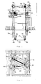
- Fig.1
- Seitenansicht einer erfindungsgemässen Anordnung eines Aufzugs mit zwei Aufzugskabinen, zwei Antrieben, zwei Treibscheiben, zwei Zugmittel und mehreren Umlenkrollen;
- Fig.2
- Draufsicht einer erfindungsgemässen Anordnung eines Aufzugs mit zwei Aufzugskabinen, zwei Antrieben, zwei Treibscheiben, zwei Zugmittel und mehreren Umlenkrollen;
- Fig.3
- Schematische Draufsicht einer erfindungsgemässen Anordnung eines Aufzugs mit zwei Aufzugskabinen, zwei Antrieben, die vor den Kabinenführungsschienen positioniert sind, zwei Treibscheiben, zwei Zugmittel, mehreren Umlenkrollen, zwei Gegengewichten, zwei Gegengewichtsführungsschienen, einer vierteiligen Kabinentüre und einer schachtseitigen Türe;
- Fig.4
- Schematische Draufsicht einer erfindungsgemässen Anordnung eines Aufzugs mit zwei Aufzugskabinen, zwei Antrieben, die je vor und hinter den Kabinenführungsschienen positioniert sind, zwei Treibscheiben, zwei Zugmittel, mehreren Umlenkrollen, zwei Gegengewichten, zwei Gegengewichtsführungsschienen, einer vierteiligen Kabinentüre und einer schachtseitigen Türe;
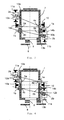
- Fig.5
- Schematische Seitenansicht einer erfindungsgemässen Anordnung eines Aufzugs mit zwei Aufzugskabinen, die jeweils als Unterflasche oder Oberfalsche aufgehängt sind, zwei Antrieben, zwei Treibscheiben, zwei Zugmittel, mehreren Umlenkrollen, zwei Gegengewichten und zwei Gegengewichtsführungsschienen;
- Fig.6
- Schematische Seitenansicht einer erfindungsgemässen Anordnung eines Aufzugs mit zwei Aufzugskabinen, die jeweils als Oberflasche aufgehängt sind, zwei Antrieben, zwei Treibscheiben, zwei Zugmittel, mehreren Umlenkrollen, zwei Gegengewichten und zwei Gegengewichtsführungsschienen;
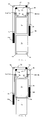
- Fig.7
- Schematische Seitenansicht einer erfindungsgemässen Anordnung eines Aufzugs mit zwei Aufzugskabinen, die obere 1:1 und die untere als Unterflasche aufgehängt, zwei Antrieben, zwei Treibscheiben, zwei Zugmittel, mehreren Umlenkrollen, zwei Gegengewichten und zwei Gegengewichtsführungsschienen; und
- Fig.8
- Schematische Seitenansicht einer erfindungsgemässen Anordnung eines Aufzugs mit zwei Aufzugskabinen, die obere 1:1 und die untere als Oberflasche aufgehängt, zwei Antrieben, zwei Antriebsscheiben, zwei Zugmittel, mehreren Umlenkrollen, zwei Gegengewichten und zwei Gegengewichtsführungsschienen;
- Fig.1
- Side view of an inventive arrangement of an elevator with two elevator cars, two Drives, two traction sheaves, two traction means and several pulleys;
- Fig.2
- Top view of an inventive arrangement of an elevator with two elevator cars, two drives, two traction sheaves, two traction means and a plurality of pulleys;
- Figure 3
- Schematic plan view of an inventive arrangement of an elevator with two elevator cars, two drives, which are positioned in front of the car guide rails, two traction sheaves, two traction means, a plurality of pulleys, two counterweights, two counterweight guide rails, a four-part car door and a shaft-side door;
- Figure 4
- Schematic plan view of an inventive arrangement of an elevator with two elevator cars, two drives, each positioned in front of and behind the car guide rails, two traction sheaves, two traction means, a plurality of pulleys, two counterweights, two counterweight guide rails, a four-part car door and a shaft-side door;
- Figure 5
- Schematic side view of an inventive arrangement of an elevator with two elevator cars, which are suspended in each case as bottom block or top wrong, two drives, two traction sheaves, two traction means, a plurality of pulleys, two counterweights and two counterweight guide rails;
- Figure 6
- Schematic side view of an inventive arrangement of an elevator with two elevator cars, which are each suspended as a top bottle, two drives, two traction sheaves, two traction means, a plurality of pulleys, two counterweights and two counterweight guide rails;
- Figure 7
- Schematic side view of an inventive arrangement of an elevator with two elevator cars, the upper 1: 1 and the lower suspended as a bottom block, two drives, two traction sheaves, two traction means, a plurality of pulleys, two counterweights and two counterweight guide rails; and
- Figure 8
- Schematic side view of an inventive arrangement of an elevator with two elevator cars, the upper 1: 1 and the lower suspended as a top bottle, two drives, two drive pulleys, two traction means, a plurality of pulleys, two counterweights and two counterweight guide rails;
Bei Kenntnis der Erfindung eröffnen sich für den Fachmann zahlreiche Möglichkeiten, die Antriebe A1, A2 im Schacht zu fixieren. Der Fachmann kann die beiden Antriebe A1, A2 auch auf dem gleichen Niveau anordnen. Diese Variante wird rein aus Platzgründen nicht gezeigt, da eine Seitenansicht der dann hintereinanderliegenden Antriebe A1, A2 beschränkt aussagekräftig ist. Jedoch zeigt die Draufsicht der
Vorteilhafterweise sind die Antriebe A1, A2 je auf einem Träger angebracht wodurch weitgehende Freiheiten in der Ausrichtung der Antriebe A1, A2 gegeben sind. In einer weiteren vorteilhaften Variante sind die Antriebe A1, A2 am selben Träger angebracht, ein oberer Antrieb A1 auf der Oberseite des Trägers und ein unterer Antrieb A2 auf der Unterseite des Trägers. Diese Anordnung der Antriebe A1, A2 ist sehr kompakt und hat den Vorteil möglichst wenig Platz im Schachtkopf zu verbauen.Advantageously, the drives A1, A2 are each mounted on a support whereby extensive freedom in the orientation of the drives A1, A2 are given. In a further advantageous variant, the drives A1, A2 are mounted on the same carrier, an upper drive A1 on the upper side of the carrier and a lower drive A2 on the underside of the carrier. This arrangement of the drives A1, A2 is very compact and has the advantage of minimizing space in the shaft head.
Der Antrieb A1, A2 bildet zusammen mit einer Treibscheibe 1a, 1b zum Antreiben des Zugmittels Z1, Z2 ein Antriebsmodul. Die Treibscheibe 1a, 1b ist so gestaltet, dass sie geeignet ist einzelne oder mehrere Zugmittel Z1, Z2 aufzunehmen. Die Zugmittel Z1, Z2 sind vorzugsweise Riemen wie Keilrippenriemen mit einseitigen Rippen, die in eine oder mehrere treibscheibenseitige Vertiefungen eingreifen. Riemenvarianten wie glatte Riemen und einseitig oder beidseitig verzahnte Riemen mit entsprechenden Antriebsscheiben 2a, 2b sind ebenfalls verwendbar. Zudem sind auch verschiedene Arten von Seilen wie Einzelseile, Doppelseile oder Mehrfachseile einsetzbar. Die Zugmittel weisen Stränge aus Stahldraht gzw. Aramidfaser auf.The drive A1, A2 forms together with a
Das Zugmittel Z1, Z2 in der
Das Zugmittel Z1, Z2 wird dabei von einem ersten Fixpunkt 13a, 13b zur ersten Umlenkrolle 2a, 2b so geführt, dass das jeweils zu einer Aufzugskabine zugeordnete Gegengewicht an den Rollen 3a, 3b als Flasche aufgehängt ist. Das Zugmittel Z1, Z2 verläuft also vom ersten Fixpunkt 13a, 13b entlang einer ersten oder zweiten Schachtwand hinunter zur Rolle 3a, 3b, umschlingt diese von Innen nach Aussen in einem Winkel von ca. 180° und führt wieder entlang einer ersten oder zweiten Schachtwand hinauf zur ersten Umlenkrolle 2a, 2b. Diese erste Umlenkrolle 2a, 2b liegt gegenüber der zugeordneten Treibscheibe 1a, 1b in der Nähe von zweiten oder ersten Schachtwänden. In der vorliegenden Ausführungsform ist die erste Umlenkrolle 2a, 2b Bestandteil eines Umlenkmoduls, das über starre balkenförmige Stäbe mit dem Antriebsmodul verbunden ist und mit diesem eine Baugruppe bildet. Der Vorteil dieser Ausführungsform liegt in der Reduzierung der Anzahl Bauteile und der damit verbundenen einfachen Montage. Zusätzlich lassen sich die Antriebs- und Umlenkmodule längs der Verbindungsstäbe verschieben, so dass eine flexible Längenanpassung der Baugruppe an die realen Abmessungen des Schachtes möglich ist. Ein weiterer Vorteil liegt im Modularen Aufbau der Baugruppe, die eine günstige Wartung oder Ersetzung derselben zulässt.The traction means Z1, Z2 is thereby guided from a first
Von der ersten Umlenkrolle 2a, 2b wird das Zugmittel Z1, Z2 nun zur Treibscheibe 1a, 1b entlang der Schachtdecke geführt und umschlingt diese Treibscheibe 1a, 1b von Innen nach Aussen in einem Umschlingungswinkel von 90 bis 180°. Im weiteren Verlauf erzeugt das Zugmittel Z1, Z2 unterhalb der Treibscheibe 1a, 1b mit zweiten 4a, 4b und dritten 5a, 5b Umlenkrollen eine Flaschenaufhängung der Aufzugskabine, indem das Zugmittel Z1, Z2 von der Treibscheibe 1a, 1b entlang ersten oder zweiten Schachtwänden hinunter zu zweiten Umlenkrollen 4a, 4b geführt wird. Das Zugmittel Z1, Z2 umschlingt die Umlenkrolle 4a, 4b von Aussen nach Innen in einem Umschlingungswinkel von ca. 90° und führt danach waagrecht zur dritten Umlenkrolle 5a, 5b. Schliesslich gelangt das Zugmittel Z1, Z2 nach Umschlingen der dritten Umlenkrolle 5a, 5b von Innen nach Aussen in einem Umschlingungswinkel von ca. 90° entlang erster oder zweiter Schachtwände hinauf zum zweiten Fixpunkt 14a, 14b.From the
Eine Einstellscheibe 6a, 6b ist optional Bestandteil des Antriebmoduls. Mit dieser Einstellscheibe 6a, 6b lässt sich der Umschlingungswinkel des Zugmittels an der Treibscheibe 1a, 1b einstellen, bzw. vergrössern oder verkleinern um die gewünschten Traktionskräfte von der Treibscheibe 1a, 1b auf das Zugmittel A1, A2 zu übertragen.A
Aus den
Zudem liegt die Achse, gebildet durch die beiden Umlenkrollen 5a, 5b und 4a, 4b, an denen die Aufzugskabine 7a, 7b aufgehängt ist, nahe an den Kabinenführungsschienen 10. Dadurch werden Momente, die durch die Aufhängungskräfte vom Zugmittel Z1, Z2 über die Aufzugskabine 7a, 7b auf die Kabinenführungsschienen 10 übertragen werden, klein gehalten.In addition, the axis formed by the two
Die platzsparende Positionierung mindestens eines Gegengewichts 12a, 12b zwischen den Kabinenführungsschienen 10 und einer dritten oder vierten Schachtwand kann dank einer besonderen Anordnung der Kabinentüre 9 realisiert werden. Im Normalbetrieb des Aufzugs werden die Aufzugskabinen 7a, 7b bei einem Stockwerkshalt bündig zum Stockwerk platziert und die Kabinentüren 9 zusammen mit den Schachttüren 8 geöffnet, um den Transfer von Passagieren vom Stockwerk zur Aufzugskabine 7a, 7b zu ermöglichen. Beim Öffnen der Kabinentüren 9 ragen dessen Schiebeelemente in den Schachtraum hinein und nehmen einengewissen andersweit unverbaubaren Schachtraum in Anspruch. Wenn die Kabinentüre 9 nicht wie üblich aus zwei Schiebelementen, sondern aus mindestens vier Schiebelementen besteht, die teleskopisch ein- bzw. ausziehbar sind, wird beim Öffnungsvorgang der Kabinentüren 9 weniger Schachtraum beansprucht. Dank der kürzeren Schiebelemente ragen diese Schiebelemente bei offener Kabinentüre 9 weniger weit in den Schachtraum und halten damit mehr Platz frei für die Gegengewichte 12a, 12b oder andere Gegenstände im Schacht, wie Elektroinstallation, Sensoren, Sicherheitseinrichtung oder Stromkasten.The space-saving positioning of at least one
Dem Fachmann stehen gemäss Erfindung verschiedene Möglichkeiten zur Verfügung, um die Aufzugskabinen 7a, 7b aufzuhängen. Je nach Platzangebot im Schachtkopf, Schachtgrube oder zwischen Stockwerken, ist eine Aufhängungsvariante optimal.According to the invention, various options are available to the person skilled in the art in order to suspend the
Die
Claims (20)
- Lift with at least two lift cages (7a, 7b) which are disposed one above the other, in a shaft, which cages are vertically movable and each have an own drive (A1, A2), each an own counterweight (12a, 12b) and each an own traction means (Z1, Z2), wherein these drives (A1, A2) are fixed in the region of the shaft head in such a manner that one drive (A1) is fixed at a first shaft wall and a further drive (A2) is fixed an opposite second shaft wall and each have at least one drive pulley (1a, 1b), wherein at least one first deflecting roller (2a, 2b) is associated with one drive (A1, A2) and is positioned on a second or first shaft wall, which is opposite this drive (A1, A2), above the counterweight (12a, 12b) associated with this drive (A1, A2), and that the traction means (Z1, Z2) is led from the counterweight (12a, 12b) over the deflecting roller (2a, 2b) to the drive pulley (1a, 1b) and from there to the lift cage (7a, 7b), characterised in that associated fixing points (13a, 13, 14a, 14b) of a traction means (Z1, Z2) lie on the same side of the lift cage (7a, 7b).
- Lift according to claim 1, characterised in that a respective first deflecting roller (2a, 2b) is associated with each of the two drives (A1, A2).
- Lift according to any one of the preceding claims, characterised in that at least one traction means (Z1, Z2) is so guided by the drive pulley (1a, 1b) and the first deflecting roller (2a, 2b) above the lift cage (7a, 7b) that the traction means (Z1, Z2) forms an acute angle with third and fourth shaft walls.
- Lift according to claim 3, characterised in that the angle is at most 20°.
- Lift according to any one of the preceding claims, characterised in that the lift cage (7a, 7b) is guided by cage guide rails (10) and that the counterweight (12a, 12b) is positionable between cage guide rails (10) and third and fourth shaft walls.
- Lift according to any one of the preceding claims, characterised in that a first lift cage (7a, 7b) is suspended in block-and-tackle manner.
- Lift according to claim 6, characterised in that the lift cage (7a, 7b) is suspended in block-and-tackle manner at second deflecting rollers (4a, 4b) and third deflecting rollers (5a, 5b) and that the traction means (Z1, Z2) is led between the drive pulley (1a, 1b) and a first fixing point (13a, 13b) via second deflecting rollers (4a, 4b) and third deflecting rollers (5a, 5b).
- Lift according to any one of the preceding claims, characterised in that the counterweight (10) is suspended in block-and-tackle manner at a fourth deflecting roller (3a, 3b), wherein the traction means (Z1, Z2) is led from the first deflecting roller (2a, 2b) downwardly to the fourth deflecting roller (3a, 3b) and from there back up to a second fixing point (14a, 14b) of the traction means (Z1, Z2).
- Lift according to any one of the preceding claims, characterised in that the traction means (Z1, Z2) consist of at least one cable or double cable.
- Lift according to any one of claims 1 to 8, characterised in that the traction means (Z1, Z2) is a belt.
- Lift according to claim 10, characterised in that the traction means (Z1, Z2) is a belt structured at one side.
- Lift according to claim 10 or 11, characterised in that the traction means (Z1, Z2) is a cogged belt, ribbed belt or V-belt.
- Lift according to any one of the preceding claims, characterised in that the belt is guided by the drive pulley (1a, 1b) and at least first deflecting rollers (2a, 2b), second deflecting rollers (4a, 4b), third deflecting rollers (5a, 5b) and fourth deflecting rollers (3a, 3b), and is disposed in contact with the drive pulley (1a, 1b) and deflecting rollers (2a, 2b, 3a, 3b, 4a, 4b, 5a, 5b) only at one side of the belt and that the belt is guided between the drive pulley (1a, 1b), the deflecting rollers (2a, 2b, 3a, 3b, 4a, 4b, 5a, 5b) and its fixing points (13a, 13b, 14a, 14b) to be substantially free of twisting.
- Lift according to any one of the preceding claims, characterised in that the drives (A1, A2) are disposed in the region of the shaft head, wherein the drives (A1, A2) are fastened at different levels.
- Lift according to any one of the preceding claims, characterised in that the drives (A1, A2) are located in the region of the shaft head, wherein the drives (A1, A2) are fastened at the same level.
- Lift according to any one of the preceding claims, characterised in that the drives (A1, A2) are positioned on the same beam.
- Lift according to any one of the preceding claims, characterised in that the drives (A1, A2) are each positioned on a respective beam.
- Lift according to any one of the preceding claims, characterised in that the lift has shaft doors (8) and a cage door (9), wherein the shaft doors (8) consist of two sliding elements and the cage door (9) consists of more than two sliding elements.
- Lift according to any one of the preceding claims, characterised in that the lift cages (7a, 7b) are guided by cage guide rails (10), wherein the two drive modules and the two associated deflecting modules each lie on a respective side of the connecting line of the cage guide rails (10).
- Lift according to any one of the preceding claims, characterised in that the lift cages (7a, 7b) are guided by cage guide rails (10), wherein the two drive modules and the two associated deflecting modules each lie on the same side of the connecting line of the cage guide rails (10).
Priority Applications (1)
| Application Number | Priority Date | Filing Date | Title |
|---|---|---|---|
| EP20070119651 EP1918238B1 (en) | 2006-10-31 | 2007-10-30 | Elevator with two superimposed cars in one shaft |
Applications Claiming Priority (2)
| Application Number | Priority Date | Filing Date | Title |
|---|---|---|---|
| EP06123294 | 2006-10-31 | ||
| EP20070119651 EP1918238B1 (en) | 2006-10-31 | 2007-10-30 | Elevator with two superimposed cars in one shaft |
Publications (2)
| Publication Number | Publication Date |
|---|---|
| EP1918238A1 EP1918238A1 (en) | 2008-05-07 |
| EP1918238B1 true EP1918238B1 (en) | 2011-03-09 |
Family
ID=39263149
Family Applications (1)
| Application Number | Title | Priority Date | Filing Date |
|---|---|---|---|
| EP20070119651 Active EP1918238B1 (en) | 2006-10-31 | 2007-10-30 | Elevator with two superimposed cars in one shaft |
Country Status (1)
| Country | Link |
|---|---|
| EP (1) | EP1918238B1 (en) |
Cited By (1)
| Publication number | Priority date | Publication date | Assignee | Title |
|---|---|---|---|---|
| DE102022119470A1 (en) | 2022-08-03 | 2024-02-08 | Tk Elevator Innovation And Operations Gmbh | Elevator system with two elevator cars arranged one above the other in an elevator shaft |
Families Citing this family (3)
| Publication number | Priority date | Publication date | Assignee | Title |
|---|---|---|---|---|
| WO2010126497A1 (en) * | 2009-04-29 | 2010-11-04 | Otis Elevator Company | Elevator system including multiple cars within a single hoistway |
| EP3000759B1 (en) * | 2014-09-25 | 2017-06-07 | KONE Corporation | Elevator |
| US10053332B2 (en) | 2016-03-25 | 2018-08-21 | Smart Lifts, Llc | Independent traction drive and suspension systems for a plurality of elevator cabs and counterweights in a hoistway |
Family Cites Families (5)
| Publication number | Priority date | Publication date | Assignee | Title |
|---|---|---|---|---|
| JP2001335259A (en) * | 2000-05-24 | 2001-12-04 | Hitachi Building Systems Co Ltd | Double layer type elevator |
| EP1329412B1 (en) * | 2000-10-10 | 2009-12-09 | Mitsubishi Denki Kabushiki Kaisha | Elevator device |
| ES2281559T3 (en) * | 2002-11-26 | 2007-10-01 | Thyssenkrupp Elevator Ag | PROCEDURE FOR THE CONTROL OF AN ELEVATOR INSTALLATION, AS WELL AS THE ELEVATOR INSTALLATION TO PERFORM THE PROCEDURE. |
| ES2590554T3 (en) * | 2004-12-16 | 2016-11-22 | Otis Elevator Company | Elevator system with multiple cabins in an elevator shaft |
| ES2341550T3 (en) * | 2005-03-12 | 2010-06-22 | Thyssenkrupp Elevator Ag | ELEVATOR SYSTEM. |
-
2007
- 2007-10-30 EP EP20070119651 patent/EP1918238B1/en active Active
Cited By (1)
| Publication number | Priority date | Publication date | Assignee | Title |
|---|---|---|---|---|
| DE102022119470A1 (en) | 2022-08-03 | 2024-02-08 | Tk Elevator Innovation And Operations Gmbh | Elevator system with two elevator cars arranged one above the other in an elevator shaft |
Also Published As
| Publication number | Publication date |
|---|---|
| EP1918238A1 (en) | 2008-05-07 |
Similar Documents
| Publication | Publication Date | Title |
|---|---|---|
| EP1326797B1 (en) | Elevator with drive unit mounted in a superior lateral section of the elevator hoistway | |
| EP1700809B1 (en) | Elevator system | |
| EP1588977B1 (en) | Device for the leveling of the cars of a multi-deck elevator | |
| EP1591404A2 (en) | Positioning of a driving machine for elevators | |
| EP1935829A1 (en) | Elevator comprising two elevator cars in a shaft | |
| EP0846645A1 (en) | Elevator with modular construction | |
| EP1056678A2 (en) | Preassembled elevator shaft | |
| EP3052420B1 (en) | Elevator installation | |
| EP1918238B1 (en) | Elevator with two superimposed cars in one shaft | |
| EP3227216B1 (en) | Elevator system | |
| DE10319731B4 (en) | elevator | |
| AT515346A2 (en) | elevator system | |
| EP3931141B1 (en) | Elevator system | |
| EP3114067B1 (en) | Drive with multiple linking element for an elevator system | |
| EP2468674A1 (en) | Lift facility with double decker | |
| AT410784B (en) | LIFT | |
| DE19963286B4 (en) | elevator | |
| WO2010072656A1 (en) | A plurality of elevator cars in an elevator shaft with improved shaft utilization | |
| WO1999064338A1 (en) | Elevator guiding device | |
| DE19963297B4 (en) | elevator | |
| WO2023011771A1 (en) | Lift system without a machine room | |
| DE102022119470A1 (en) | Elevator system with two elevator cars arranged one above the other in an elevator shaft | |
| EP1935828B1 (en) | Lift system for a building with at least two floors | |
| DE19963296A1 (en) | Elevator has control unit for elevator drive contained between parts of elevator shaft used for displacement of elevator cabin and displacement of counter-weight | |
| EP3235770A1 (en) | Method for retrofitting an elevator and corresponding elevator |
Legal Events
| Date | Code | Title | Description |
|---|---|---|---|
| PUAI | Public reference made under article 153(3) epc to a published international application that has entered the european phase |
Free format text: ORIGINAL CODE: 0009012 |
|
| AK | Designated contracting states |
Kind code of ref document: A1 Designated state(s): AT BE BG CH CY CZ DE DK EE ES FI FR GB GR HU IE IS IT LI LT LU LV MC MT NL PL PT RO SE SI SK TR |
|
| AX | Request for extension of the european patent |
Extension state: AL BA HR MK RS |
|
| 17P | Request for examination filed |
Effective date: 20081106 |
|
| 17Q | First examination report despatched |
Effective date: 20081212 |
|
| AKX | Designation fees paid |
Designated state(s): AT BE BG CH CY CZ DE DK EE ES FI FR GB GR HU IE IS IT LI LT LU LV MC MT NL PL PT RO SE SI SK TR |
|
| REG | Reference to a national code |
Ref country code: HK Ref legal event code: DE Ref document number: 1120013 Country of ref document: HK |
|
| GRAP | Despatch of communication of intention to grant a patent |
Free format text: ORIGINAL CODE: EPIDOSNIGR1 |
|
| GRAS | Grant fee paid |
Free format text: ORIGINAL CODE: EPIDOSNIGR3 |
|
| GRAA | (expected) grant |
Free format text: ORIGINAL CODE: 0009210 |
|
| AK | Designated contracting states |
Kind code of ref document: B1 Designated state(s): AT BE BG CH CY CZ DE DK EE ES FI FR GB GR HU IE IS IT LI LT LU LV MC MT NL PL PT RO SE SI SK TR |
|
| REG | Reference to a national code |
Ref country code: GB Ref legal event code: FG4D Free format text: NOT ENGLISH |
|
| REG | Reference to a national code |
Ref country code: CH Ref legal event code: EP |
|
| REG | Reference to a national code |
Ref country code: IE Ref legal event code: FG4D Free format text: LANGUAGE OF EP DOCUMENT: GERMAN |
|
| REF | Corresponds to: |
Ref document number: 502007006652 Country of ref document: DE Date of ref document: 20110421 Kind code of ref document: P |
|
| REG | Reference to a national code |
Ref country code: DE Ref legal event code: R096 Ref document number: 502007006652 Country of ref document: DE Effective date: 20110421 |
|
| REG | Reference to a national code |
Ref country code: NL Ref legal event code: VDEP Effective date: 20110309 |
|
| PG25 | Lapsed in a contracting state [announced via postgrant information from national office to epo] |
Ref country code: LV Free format text: LAPSE BECAUSE OF FAILURE TO SUBMIT A TRANSLATION OF THE DESCRIPTION OR TO PAY THE FEE WITHIN THE PRESCRIBED TIME-LIMIT Effective date: 20110309 Ref country code: SE Free format text: LAPSE BECAUSE OF FAILURE TO SUBMIT A TRANSLATION OF THE DESCRIPTION OR TO PAY THE FEE WITHIN THE PRESCRIBED TIME-LIMIT Effective date: 20110309 Ref country code: ES Free format text: LAPSE BECAUSE OF FAILURE TO SUBMIT A TRANSLATION OF THE DESCRIPTION OR TO PAY THE FEE WITHIN THE PRESCRIBED TIME-LIMIT Effective date: 20110620 Ref country code: GR Free format text: LAPSE BECAUSE OF FAILURE TO SUBMIT A TRANSLATION OF THE DESCRIPTION OR TO PAY THE FEE WITHIN THE PRESCRIBED TIME-LIMIT Effective date: 20110610 Ref country code: LT Free format text: LAPSE BECAUSE OF FAILURE TO SUBMIT A TRANSLATION OF THE DESCRIPTION OR TO PAY THE FEE WITHIN THE PRESCRIBED TIME-LIMIT Effective date: 20110309 |
|
| LTIE | Lt: invalidation of european patent or patent extension |
Effective date: 20110309 |
|
| PG25 | Lapsed in a contracting state [announced via postgrant information from national office to epo] |
Ref country code: BG Free format text: LAPSE BECAUSE OF FAILURE TO SUBMIT A TRANSLATION OF THE DESCRIPTION OR TO PAY THE FEE WITHIN THE PRESCRIBED TIME-LIMIT Effective date: 20110609 Ref country code: SI Free format text: LAPSE BECAUSE OF FAILURE TO SUBMIT A TRANSLATION OF THE DESCRIPTION OR TO PAY THE FEE WITHIN THE PRESCRIBED TIME-LIMIT Effective date: 20110309 Ref country code: FI Free format text: LAPSE BECAUSE OF FAILURE TO SUBMIT A TRANSLATION OF THE DESCRIPTION OR TO PAY THE FEE WITHIN THE PRESCRIBED TIME-LIMIT Effective date: 20110309 Ref country code: NL Free format text: LAPSE BECAUSE OF FAILURE TO SUBMIT A TRANSLATION OF THE DESCRIPTION OR TO PAY THE FEE WITHIN THE PRESCRIBED TIME-LIMIT Effective date: 20110309 Ref country code: CY Free format text: LAPSE BECAUSE OF FAILURE TO SUBMIT A TRANSLATION OF THE DESCRIPTION OR TO PAY THE FEE WITHIN THE PRESCRIBED TIME-LIMIT Effective date: 20110309 |
|
| REG | Reference to a national code |
Ref country code: HK Ref legal event code: GR Ref document number: 1120013 Country of ref document: HK |
|
| REG | Reference to a national code |
Ref country code: IE Ref legal event code: FD4D |
|
| PG25 | Lapsed in a contracting state [announced via postgrant information from national office to epo] |
Ref country code: IE Free format text: LAPSE BECAUSE OF FAILURE TO SUBMIT A TRANSLATION OF THE DESCRIPTION OR TO PAY THE FEE WITHIN THE PRESCRIBED TIME-LIMIT Effective date: 20110309 Ref country code: PT Free format text: LAPSE BECAUSE OF FAILURE TO SUBMIT A TRANSLATION OF THE DESCRIPTION OR TO PAY THE FEE WITHIN THE PRESCRIBED TIME-LIMIT Effective date: 20110711 Ref country code: EE Free format text: LAPSE BECAUSE OF FAILURE TO SUBMIT A TRANSLATION OF THE DESCRIPTION OR TO PAY THE FEE WITHIN THE PRESCRIBED TIME-LIMIT Effective date: 20110309 |
|
| PG25 | Lapsed in a contracting state [announced via postgrant information from national office to epo] |
Ref country code: CZ Free format text: LAPSE BECAUSE OF FAILURE TO SUBMIT A TRANSLATION OF THE DESCRIPTION OR TO PAY THE FEE WITHIN THE PRESCRIBED TIME-LIMIT Effective date: 20110309 Ref country code: SK Free format text: LAPSE BECAUSE OF FAILURE TO SUBMIT A TRANSLATION OF THE DESCRIPTION OR TO PAY THE FEE WITHIN THE PRESCRIBED TIME-LIMIT Effective date: 20110309 Ref country code: RO Free format text: LAPSE BECAUSE OF FAILURE TO SUBMIT A TRANSLATION OF THE DESCRIPTION OR TO PAY THE FEE WITHIN THE PRESCRIBED TIME-LIMIT Effective date: 20110309 Ref country code: IS Free format text: LAPSE BECAUSE OF FAILURE TO SUBMIT A TRANSLATION OF THE DESCRIPTION OR TO PAY THE FEE WITHIN THE PRESCRIBED TIME-LIMIT Effective date: 20110709 |
|
| PLBE | No opposition filed within time limit |
Free format text: ORIGINAL CODE: 0009261 |
|
| STAA | Information on the status of an ep patent application or granted ep patent |
Free format text: STATUS: NO OPPOSITION FILED WITHIN TIME LIMIT |
|
| 26N | No opposition filed |
Effective date: 20111212 |
|
| PG25 | Lapsed in a contracting state [announced via postgrant information from national office to epo] |
Ref country code: DK Free format text: LAPSE BECAUSE OF FAILURE TO SUBMIT A TRANSLATION OF THE DESCRIPTION OR TO PAY THE FEE WITHIN THE PRESCRIBED TIME-LIMIT Effective date: 20110309 Ref country code: PL Free format text: LAPSE BECAUSE OF FAILURE TO SUBMIT A TRANSLATION OF THE DESCRIPTION OR TO PAY THE FEE WITHIN THE PRESCRIBED TIME-LIMIT Effective date: 20110309 |
|
| REG | Reference to a national code |
Ref country code: DE Ref legal event code: R097 Ref document number: 502007006652 Country of ref document: DE Effective date: 20111212 |
|
| BERE | Be: lapsed |
Owner name: INVENTIO A.G. Effective date: 20111031 |
|
| PG25 | Lapsed in a contracting state [announced via postgrant information from national office to epo] |
Ref country code: MC Free format text: LAPSE BECAUSE OF NON-PAYMENT OF DUE FEES Effective date: 20111031 |
|
| PG25 | Lapsed in a contracting state [announced via postgrant information from national office to epo] |
Ref country code: BE Free format text: LAPSE BECAUSE OF NON-PAYMENT OF DUE FEES Effective date: 20111031 |
|
| PG25 | Lapsed in a contracting state [announced via postgrant information from national office to epo] |
Ref country code: MT Free format text: LAPSE BECAUSE OF FAILURE TO SUBMIT A TRANSLATION OF THE DESCRIPTION OR TO PAY THE FEE WITHIN THE PRESCRIBED TIME-LIMIT Effective date: 20110309 |
|
| PG25 | Lapsed in a contracting state [announced via postgrant information from national office to epo] |
Ref country code: LU Free format text: LAPSE BECAUSE OF NON-PAYMENT OF DUE FEES Effective date: 20111030 |
|
| PG25 | Lapsed in a contracting state [announced via postgrant information from national office to epo] |
Ref country code: TR Free format text: LAPSE BECAUSE OF FAILURE TO SUBMIT A TRANSLATION OF THE DESCRIPTION OR TO PAY THE FEE WITHIN THE PRESCRIBED TIME-LIMIT Effective date: 20110309 |
|
| PG25 | Lapsed in a contracting state [announced via postgrant information from national office to epo] |
Ref country code: HU Free format text: LAPSE BECAUSE OF FAILURE TO SUBMIT A TRANSLATION OF THE DESCRIPTION OR TO PAY THE FEE WITHIN THE PRESCRIBED TIME-LIMIT Effective date: 20110309 |
|
| REG | Reference to a national code |
Ref country code: AT Ref legal event code: MM01 Ref document number: 501078 Country of ref document: AT Kind code of ref document: T Effective date: 20121031 |
|
| PG25 | Lapsed in a contracting state [announced via postgrant information from national office to epo] |
Ref country code: AT Free format text: LAPSE BECAUSE OF NON-PAYMENT OF DUE FEES Effective date: 20121031 |
|
| REG | Reference to a national code |
Ref country code: FR Ref legal event code: PLFP Year of fee payment: 9 |
|
| PGFP | Annual fee paid to national office [announced via postgrant information from national office to epo] |
Ref country code: CH Payment date: 20151029 Year of fee payment: 9 Ref country code: GB Payment date: 20151021 Year of fee payment: 9 Ref country code: IT Payment date: 20151028 Year of fee payment: 9 |
|
| REG | Reference to a national code |
Ref country code: FR Ref legal event code: PLFP Year of fee payment: 10 |
|
| REG | Reference to a national code |
Ref country code: CH Ref legal event code: PL |
|
| GBPC | Gb: european patent ceased through non-payment of renewal fee |
Effective date: 20161030 |
|
| PG25 | Lapsed in a contracting state [announced via postgrant information from national office to epo] |
Ref country code: GB Free format text: LAPSE BECAUSE OF NON-PAYMENT OF DUE FEES Effective date: 20161030 Ref country code: CH Free format text: LAPSE BECAUSE OF NON-PAYMENT OF DUE FEES Effective date: 20161031 Ref country code: LI Free format text: LAPSE BECAUSE OF NON-PAYMENT OF DUE FEES Effective date: 20161031 |
|
| REG | Reference to a national code |
Ref country code: FR Ref legal event code: PLFP Year of fee payment: 11 |
|
| PG25 | Lapsed in a contracting state [announced via postgrant information from national office to epo] |
Ref country code: IT Free format text: LAPSE BECAUSE OF NON-PAYMENT OF DUE FEES Effective date: 20161030 |
|
| REG | Reference to a national code |
Ref country code: FR Ref legal event code: PLFP Year of fee payment: 12 |
|
| PGFP | Annual fee paid to national office [announced via postgrant information from national office to epo] |
Ref country code: FR Payment date: 20211027 Year of fee payment: 15 |
|
| REG | Reference to a national code |
Ref country code: DE Ref legal event code: R084 Ref document number: 502007006652 Country of ref document: DE |
|
| PG25 | Lapsed in a contracting state [announced via postgrant information from national office to epo] |
Ref country code: FR Free format text: LAPSE BECAUSE OF NON-PAYMENT OF DUE FEES Effective date: 20221031 |
|
| PGFP | Annual fee paid to national office [announced via postgrant information from national office to epo] |
Ref country code: DE Payment date: 20231027 Year of fee payment: 17 |