EP3635845B1 - Near-field antennas for accumulating energy at a near-field distance with minimal far-field gain - Google Patents
Near-field antennas for accumulating energy at a near-field distance with minimal far-field gain Download PDFInfo
- Publication number
- EP3635845B1 EP3635845B1 EP18797695.6A EP18797695A EP3635845B1 EP 3635845 B1 EP3635845 B1 EP 3635845B1 EP 18797695 A EP18797695 A EP 18797695A EP 3635845 B1 EP3635845 B1 EP 3635845B1
- Authority
- EP
- European Patent Office
- Prior art keywords
- conductive plate
- cutouts
- field
- energy
- field antenna
- Prior art date
- Legal status (The legal status is an assumption and is not a legal conclusion. Google has not performed a legal analysis and makes no representation as to the accuracy of the status listed.)
- Active
Links
Images


Classifications
-
- H—ELECTRICITY
- H02—GENERATION; CONVERSION OR DISTRIBUTION OF ELECTRIC POWER
- H02J—ELECTRIC POWER NETWORKS; CIRCUIT ARRANGEMENTS OR SYSTEMS FOR SUPPLYING OR DISTRIBUTING ELECTRIC POWER; SYSTEMS FOR STORING ELECTRIC ENERGY
- H02J50/00—Circuit arrangements or systems for wireless supply or distribution of electric power
- H02J50/20—Circuit arrangements or systems for wireless supply or distribution of electric power using microwaves or radio frequency waves
- H02J50/23—Circuit arrangements or systems for wireless supply or distribution of electric power using microwaves or radio frequency waves characterised by the type of transmitting antennas, e.g. directional array antennas or Yagi antennas
-
- B—PERFORMING OPERATIONS; TRANSPORTING
- B60—VEHICLES IN GENERAL
- B60L—PROPULSION OF ELECTRICALLY-PROPELLED VEHICLES; SUPPLYING ELECTRIC POWER FOR AUXILIARY EQUIPMENT OF ELECTRICALLY-PROPELLED VEHICLES; ELECTRODYNAMIC BRAKE SYSTEMS FOR VEHICLES IN GENERAL; MAGNETIC SUSPENSION OR LEVITATION FOR VEHICLES; MONITORING OPERATING VARIABLES OF ELECTRICALLY-PROPELLED VEHICLES; ELECTRIC SAFETY DEVICES FOR ELECTRICALLY-PROPELLED VEHICLES
- B60L53/00—Methods of charging batteries, specially adapted for electric vehicles; Charging stations or on-board charging equipment therefor; Exchange of energy storage elements in electric vehicles
- B60L53/10—Methods of charging batteries, specially adapted for electric vehicles; Charging stations or on-board charging equipment therefor; Exchange of energy storage elements in electric vehicles characterised by the energy transfer between the charging station and the vehicle
- B60L53/12—Inductive energy transfer
-
- H—ELECTRICITY
- H01—ELECTRIC ELEMENTS
- H01F—MAGNETS; INDUCTANCES; TRANSFORMERS; SELECTION OF MATERIALS FOR THEIR MAGNETIC PROPERTIES
- H01F38/00—Adaptations of transformers or inductances for specific applications or functions
- H01F38/14—Inductive couplings
-
- H—ELECTRICITY
- H01—ELECTRIC ELEMENTS
- H01Q—ANTENNAS, i.e. RADIO AERIALS
- H01Q1/00—Details of, or arrangements associated with, antennas
- H01Q1/36—Structural form of radiating elements, e.g. cone, spiral, umbrella; Particular materials used therewith
- H01Q1/38—Structural form of radiating elements, e.g. cone, spiral, umbrella; Particular materials used therewith formed by a conductive layer on an insulating support
-
- H—ELECTRICITY
- H01—ELECTRIC ELEMENTS
- H01Q—ANTENNAS, i.e. RADIO AERIALS
- H01Q13/00—Waveguide horns or mouths; Slot antennas; Leaky-waveguide antennas; Equivalent structures causing radiation along the transmission path of a guided wave
- H01Q13/10—Resonant slot antennas
-
- H—ELECTRICITY
- H01—ELECTRIC ELEMENTS
- H01Q—ANTENNAS, i.e. RADIO AERIALS
- H01Q9/00—Electrically-short antennas having dimensions not more than twice the operating wavelength and consisting of conductive active radiating elements
- H01Q9/04—Resonant antennas
- H01Q9/0407—Substantially flat resonant element parallel to ground plane, e.g. patch antenna
- H01Q9/0414—Substantially flat resonant element parallel to ground plane, e.g. patch antenna in a stacked or folded configuration
-
- H—ELECTRICITY
- H02—GENERATION; CONVERSION OR DISTRIBUTION OF ELECTRIC POWER
- H02J—ELECTRIC POWER NETWORKS; CIRCUIT ARRANGEMENTS OR SYSTEMS FOR SUPPLYING OR DISTRIBUTING ELECTRIC POWER; SYSTEMS FOR STORING ELECTRIC ENERGY
- H02J50/00—Circuit arrangements or systems for wireless supply or distribution of electric power
- H02J50/001—Energy harvesting or scavenging
-
- H—ELECTRICITY
- H02—GENERATION; CONVERSION OR DISTRIBUTION OF ELECTRIC POWER
- H02J—ELECTRIC POWER NETWORKS; CIRCUIT ARRANGEMENTS OR SYSTEMS FOR SUPPLYING OR DISTRIBUTING ELECTRIC POWER; SYSTEMS FOR STORING ELECTRIC ENERGY
- H02J50/00—Circuit arrangements or systems for wireless supply or distribution of electric power
- H02J50/005—Mechanical details of housing or structure aiming to accommodate the power transfer means, e.g. mechanical integration of coils, antennas or transducers into emitting or receiving devices
-
- H—ELECTRICITY
- H02—GENERATION; CONVERSION OR DISTRIBUTION OF ELECTRIC POWER
- H02J—ELECTRIC POWER NETWORKS; CIRCUIT ARRANGEMENTS OR SYSTEMS FOR SUPPLYING OR DISTRIBUTING ELECTRIC POWER; SYSTEMS FOR STORING ELECTRIC ENERGY
- H02J50/00—Circuit arrangements or systems for wireless supply or distribution of electric power
- H02J50/10—Circuit arrangements or systems for wireless supply or distribution of electric power using inductive coupling
- H02J50/12—Circuit arrangements or systems for wireless supply or distribution of electric power using inductive coupling of the resonant type
-
- H—ELECTRICITY
- H02—GENERATION; CONVERSION OR DISTRIBUTION OF ELECTRIC POWER
- H02J—ELECTRIC POWER NETWORKS; CIRCUIT ARRANGEMENTS OR SYSTEMS FOR SUPPLYING OR DISTRIBUTING ELECTRIC POWER; SYSTEMS FOR STORING ELECTRIC ENERGY
- H02J50/00—Circuit arrangements or systems for wireless supply or distribution of electric power
- H02J50/20—Circuit arrangements or systems for wireless supply or distribution of electric power using microwaves or radio frequency waves
- H02J50/27—Circuit arrangements or systems for wireless supply or distribution of electric power using microwaves or radio frequency waves characterised by the type of receiving antennas, e.g. rectennas
-
- H—ELECTRICITY
- H02—GENERATION; CONVERSION OR DISTRIBUTION OF ELECTRIC POWER
- H02J—ELECTRIC POWER NETWORKS; CIRCUIT ARRANGEMENTS OR SYSTEMS FOR SUPPLYING OR DISTRIBUTING ELECTRIC POWER; SYSTEMS FOR STORING ELECTRIC ENERGY
- H02J50/00—Circuit arrangements or systems for wireless supply or distribution of electric power
- H02J50/40—Circuit arrangements or systems for wireless supply or distribution of electric power using two or more transmitting or receiving devices
- H02J50/402—Circuit arrangements or systems for wireless supply or distribution of electric power using two or more transmitting or receiving devices the two or more transmitting or the two or more receiving devices being integrated in the same unit, e.g. power mats with several coils or antennas with several sub-antennas
-
- H—ELECTRICITY
- H02—GENERATION; CONVERSION OR DISTRIBUTION OF ELECTRIC POWER
- H02J—ELECTRIC POWER NETWORKS; CIRCUIT ARRANGEMENTS OR SYSTEMS FOR SUPPLYING OR DISTRIBUTING ELECTRIC POWER; SYSTEMS FOR STORING ELECTRIC ENERGY
- H02J7/00—Circuit arrangements for charging or discharging batteries or for supplying loads from batteries
- H02J7/70—Circuit arrangements for charging or discharging batteries or for supplying loads from batteries characterised by the mechanical construction
-
- H—ELECTRICITY
- H04—ELECTRIC COMMUNICATION TECHNIQUE
- H04B—TRANSMISSION
- H04B5/00—Near-field transmission systems, e.g. inductive or capacitive transmission systems
- H04B5/20—Near-field transmission systems, e.g. inductive or capacitive transmission systems characterised by the transmission technique; characterised by the transmission medium
- H04B5/22—Capacitive coupling
-
- H—ELECTRICITY
- H04—ELECTRIC COMMUNICATION TECHNIQUE
- H04B—TRANSMISSION
- H04B5/00—Near-field transmission systems, e.g. inductive or capacitive transmission systems
- H04B5/40—Near-field transmission systems, e.g. inductive or capacitive transmission systems characterised by components specially adapted for near-field transmission
- H04B5/43—Antennas
-
- H—ELECTRICITY
- H04—ELECTRIC COMMUNICATION TECHNIQUE
- H04B—TRANSMISSION
- H04B5/00—Near-field transmission systems, e.g. inductive or capacitive transmission systems
- H04B5/70—Near-field transmission systems, e.g. inductive or capacitive transmission systems specially adapted for specific purposes
- H04B5/72—Near-field transmission systems, e.g. inductive or capacitive transmission systems specially adapted for specific purposes for local intradevice communication
-
- H—ELECTRICITY
- H01—ELECTRIC ELEMENTS
- H01Q—ANTENNAS, i.e. RADIO AERIALS
- H01Q1/00—Details of, or arrangements associated with, antennas
- H01Q1/12—Supports; Mounting means
- H01Q1/22—Supports; Mounting means by structural association with other equipment or articles
- H01Q1/24—Supports; Mounting means by structural association with other equipment or articles with receiving set
- H01Q1/241—Supports; Mounting means by structural association with other equipment or articles with receiving set used in mobile communications, e.g. GSM
- H01Q1/242—Supports; Mounting means by structural association with other equipment or articles with receiving set used in mobile communications, e.g. GSM specially adapted for hand-held use
- H01Q1/243—Supports; Mounting means by structural association with other equipment or articles with receiving set used in mobile communications, e.g. GSM specially adapted for hand-held use with built-in antennas
-
- H—ELECTRICITY
- H02—GENERATION; CONVERSION OR DISTRIBUTION OF ELECTRIC POWER
- H02J—ELECTRIC POWER NETWORKS; CIRCUIT ARRANGEMENTS OR SYSTEMS FOR SUPPLYING OR DISTRIBUTING ELECTRIC POWER; SYSTEMS FOR STORING ELECTRIC ENERGY
- H02J2105/00—Networks for supplying or distributing electric power characterised by their spatial reach or by the load
- H02J2105/40—Networks for supplying or distributing electric power characterised by their spatial reach or by the load characterised by the loads connecting to the networks or being supplied by the networks
- H02J2105/44—Portable electronic devices
-
- H—ELECTRICITY
- H02—GENERATION; CONVERSION OR DISTRIBUTION OF ELECTRIC POWER
- H02J—ELECTRIC POWER NETWORKS; CIRCUIT ARRANGEMENTS OR SYSTEMS FOR SUPPLYING OR DISTRIBUTING ELECTRIC POWER; SYSTEMS FOR STORING ELECTRIC ENERGY
- H02J50/00—Circuit arrangements or systems for wireless supply or distribution of electric power
-
- Y—GENERAL TAGGING OF NEW TECHNOLOGICAL DEVELOPMENTS; GENERAL TAGGING OF CROSS-SECTIONAL TECHNOLOGIES SPANNING OVER SEVERAL SECTIONS OF THE IPC; TECHNICAL SUBJECTS COVERED BY FORMER USPC CROSS-REFERENCE ART COLLECTIONS [XRACs] AND DIGESTS
- Y02—TECHNOLOGIES OR APPLICATIONS FOR MITIGATION OR ADAPTATION AGAINST CLIMATE CHANGE
- Y02T—CLIMATE CHANGE MITIGATION TECHNOLOGIES RELATED TO TRANSPORTATION
- Y02T10/00—Road transport of goods or passengers
- Y02T10/60—Other road transportation technologies with climate change mitigation effect
- Y02T10/70—Energy storage systems for electromobility, e.g. batteries
-
- Y—GENERAL TAGGING OF NEW TECHNOLOGICAL DEVELOPMENTS; GENERAL TAGGING OF CROSS-SECTIONAL TECHNOLOGIES SPANNING OVER SEVERAL SECTIONS OF THE IPC; TECHNICAL SUBJECTS COVERED BY FORMER USPC CROSS-REFERENCE ART COLLECTIONS [XRACs] AND DIGESTS
- Y02—TECHNOLOGIES OR APPLICATIONS FOR MITIGATION OR ADAPTATION AGAINST CLIMATE CHANGE
- Y02T—CLIMATE CHANGE MITIGATION TECHNOLOGIES RELATED TO TRANSPORTATION
- Y02T10/00—Road transport of goods or passengers
- Y02T10/60—Other road transportation technologies with climate change mitigation effect
- Y02T10/7072—Electromobility specific charging systems or methods for batteries, ultracapacitors, supercapacitors or double-layer capacitors
-
- Y—GENERAL TAGGING OF NEW TECHNOLOGICAL DEVELOPMENTS; GENERAL TAGGING OF CROSS-SECTIONAL TECHNOLOGIES SPANNING OVER SEVERAL SECTIONS OF THE IPC; TECHNICAL SUBJECTS COVERED BY FORMER USPC CROSS-REFERENCE ART COLLECTIONS [XRACs] AND DIGESTS
- Y02—TECHNOLOGIES OR APPLICATIONS FOR MITIGATION OR ADAPTATION AGAINST CLIMATE CHANGE
- Y02T—CLIMATE CHANGE MITIGATION TECHNOLOGIES RELATED TO TRANSPORTATION
- Y02T90/00—Enabling technologies or technologies with a potential or indirect contribution to GHG emissions mitigation
- Y02T90/10—Technologies relating to charging of electric vehicles
- Y02T90/14—Plug-in electric vehicles
Definitions
- the present disclosure relates generally to wireless power transmission, and more particularly to near-field antennas (e.g., non-inductive, resonant near-field antennas) that accumulate energy at a near-field distance to wirelessly deliver power to a receiver.
- near-field antennas e.g., non-inductive, resonant near-field antennas
- Portable electronic devices such as smartphones, tablets, notebooks and other electronic devices have become a necessity for communicating and interacting with others.
- the frequent use of portable electronic devices uses a significant amount of power, which quickly depletes the batteries attached to these devices.
- Inductive charging pads and corresponding inductive coils in portable devices allow users to wirelessly charge a device by placing the device at a particular position on an inductive pad to allow for a contact-based charging of the device due to magnetic coupling between respective coils in the inductive pad and in the device.
- inductive charging pads suffer from many drawbacks. For one, users typically must place their devices at a specific position and in a certain orientation on the charging pad because gaps ("dead zones” or “cold zones”) exist on the surface of the charging pad. In other words, for optimal charging, the coil in the charging pad needs to be aligned with the coil in the device in order for the required magnetic coupling to occur. Additionally, placement of other metallic objects near an inductive charging pad may interfere with operation of the inductive charging pad, so even if the user places their device at the exact right position, if another metal object is also on the pad, then magnetic coupling still may not occur and the device will not be charged by the inductive charging pad. This results in a frustrating experience for many users as they may be unable to properly charge their devices. Also, inductive charging requires a relatively large receiver coil to be placed within a device to be charged, which is less than ideal for devices where internal space is at a premium.
- DE102014219679A1 describes a near field power supply device that has a layer stack with a first conductive layer, a second conductive layer and a dielectric layer arranged between the first conductive layer and the second conductive layer.
- the control unit generates a high frequency field between the first and the second conducive layer.
- the first conductive layer includes a plurality of cutouts for allowing passage of the high frequency field to generate a near field for power supply.
- these charging pads include a plurality of near-field antennas (e.g., non-inductive resonant near-field antennas), and a method of operating one such near-field antenna is described below.
- references to near-field transmission cover the radiation of electromagnetic waves for distances up to and including 1 to 5 millimeters away from a surface of a charging pad transmitter, while references to far-field transmission cover radiation of electromagnetic waves for distances over 5 millimeters (and up to 30 feet away from a far-field transmitter).
- references to near-field transmission cover the radiation of electromagnetic waves for distances up to a quarter wavelength of an operating frequency (e.g., a quarter wavelength of an operating frequency of 5.8 GHz is approximately 12.922 millimeters).
- the operating frequency ranges from 400 MHz to 60 GHz.
- a near-field antenna for transmitting radio frequency (RF) power transmission signals includes a conductive plate having first and second opposing planar surfaces, and at least two cutouts (also referred to herein as at least two slots) extending through the conductive plate from the first surface to the second surface.
- the near-field antenna also includes an insulator and a feed element separated from the first surface of the conductive plate by the insulator. The feed element is configured to direct a plurality of RF power transmission signals towards the conductive plate.
- At least some of the radio frequency power transmission signals of the plurality of RF power transmission signals are configured to radiate through the at least two cutouts and accumulate within a near-field distance of the conductive plate to create at least two distinct zones of accumulated RF energy at each of the at least two cutouts.
- the at least two distinct zones of accumulated RF energy at each of the at least two cutouts are defined based, at least in part, on: (i) a set of dimensions defining each of the at least two cutouts, and (ii) an arrangement of the at least two cutouts.
- a first cutout of the at least two cutouts forms a first meandering line pattern and a second cutout of the at least two cutouts forms a second meandering line pattern.
- a shape of the first meandering line pattern mirrors a shape of the second meandering line pattern
- the first and second meandering line patterns have the same set of dimensions
- the shape of the first meandering line pattern is rotated (e.g., rotated 180 degrees) with respect to the shape of the second meandering line pattern.
- the shape of the first meandering line pattern is interleaved with the shape of the second meandering line pattern (e.g., two U-shaped patterns with a leg of each U-shaped pattern being interleaved or interposed between the two legs of the other U-shaped pattern, as shown in Figure 2 and described in more detail below).
- a single cutout forms a symmetrical meandering line pattern (e.g., as shown in Figure 5A ).
- a respective total length of a respective cutout of the at least two cutouts is at least as large as a wavelength of a respective RF power transmission signal of the plurality of RF power transmission signals, wherein the respective total length of the respective cutout is a combined length of each portion of the respective cutout.
- the respective cutout includes, at least: (i) a first cutout portion defined in a first direction, and (ii) a second cutout portion defined in a second direction, the second direction being orthogonal to the first direction. Furthermore, a first of the at least two distinct zones of accumulated RF energy is created at the first cutout portion (e.g., formed along the first cutout portion and along the first direction) and a second of the at least two distinct zones of accumulated RF energy is created at the second cutout portion (e.g., formed along the second cutout portion and along the second direction).
- the feed element is at least a component of a patch antenna, where the insulator is disposed between the feed element and the conductive plate; or the feed element is a component of a patch antenna that is at least partially encapsulated within the insulator, and further wherein the insulator is selected from the group consisting of: a polymer, a fiber reinforced polymer, glass, and air.
- the at least two distinct zones cover at least 80% of a surface area of the second surface of the conductive plate, preferably wherein the at least two distinct zones cover at least 90% of the surface area of the second surface of the conductive plate.
- the at least two distinct zones of accumulated RF energy extend no more than 5 millimeters (mm) above the second surface of the conductive plate, preferably wherein the at least two distinct zones of accumulated RF energy extend no more than 4 millimeters above the second surface of the conductive plate, preferably wherein the at least two distinct zones of accumulated RF energy extend no more than 3 millimeters above the second surface of the conductive plate.
- the feed element is configured to transmit each of the plurality of RF power transmission signals at a frequency selected from the group consisting of: 5.8 GHz, 2.4 GHz, and 900 MHz.
- the near-field antenna is a first near-field antenna and is part of a near-field charging pad (e.g., transmitter pad 100, Figures 1A-1B ) that also includes a second near-field antenna that is positioned adjacent to the first near-field antenna within the near-field charging pad. Furthermore, respective cutouts associated with the second near-field antenna are rotated relative to the at least two cutouts associated with the first near-field antenna.
- a near-field charging pad e.g., transmitter pad 100, Figures 1A-1B
- respective cutouts associated with the second near-field antenna are rotated relative to the at least two cutouts associated with the first near-field antenna.
- the feed element is configured to receive the one or more RF power transmission signals from a power amplifier in response to determining that a wireless power receiver is placed within a predetermined distance of the surface, preferably wherein the predetermined distance is less than approximately 5 mm away from the surface.
- the near-field antenna of A10 is configured to monitor the predetermined distance by measuring a signal strength level associated with a transmission received by a processor connected to (e.g., in electrical communication with) the near-field antenna and the signal strength level is associated with a broadcasted signal received from the wireless power receiver.
- the near-field antenna of any of A1-A5 further comprises a conductive housing surrounding the feed element and the insulator. Furthermore, the conductive housing defines an opening at one end of the housing and the conductive plate closes the opening.
- the conductive plate is a first conductive plate
- the near-field antenna further includes another insulator (e.g., a dielectric layer) disposed on the second surface of the first conductive plate and a second conductive plate disposed on top of the other insulator.
- the second conductive plate includes one or more additional cutouts.
- the near-field antenna instead of a second conductive plate, the near-field antenna further includes a conductive layer deposited on a surface of the other insulator.
- the conductive plate is a conductive layer deposited on a surface of the insulator.
- the insulator is a dielectric layer that is deposited on the first surface of the conductive plate.
- the insulator is a first insulator
- the near-field antenna further includes a second insulator that separates the feed element from a grounding plate (e.g., grounding plate 308, Figure 3A ).
- a grounding plate e.g., grounding plate 308, Figure 3A
- a method of fabricating a near-field antenna includes selecting a set of dimensions for at least two cutouts to be defined through a conductive plate of a near-field antenna, the conductive plate having opposing first and second planar surfaces. The method further includes forming the at least two cutouts through the first and second surfaces of the conductive plate in a predefined arrangement, each of the at least two cutouts having the set of dimensions.
- the method further includes coupling an insulator to the first surface of the conductive plate and coupling a feed element to the insulator, the feed element being separated from the first surface of the conductive plate by the insulator, wherein the feed element is configured to direct a plurality of radio frequency (RF) power transmission signals towards the conductive plate, at least some of the RF power transmission signals of the plurality of RF power transmission signals radiate through the at least two cutouts and accumulate within a near-field distance of the conductive plate to create at least two distinct zones of accumulated RF energy at each of the at least two cutouts.
- RF radio frequency
- the at least two distinct zones of accumulated RF energy at each of the at least two cutouts are defined based, at least in part, on: (i) a set of dimensions defining each of the at least two cutouts, and (ii) an arrangement of the at least two cutouts, wherein a first cutout of the at least two cutouts forms a first meandering line pattern and a second cutout of the at least two cutouts forms a second meandering line pattern.
- the near-field antenna is further configured in accordance with any of A1-A12.
- FIG. 1A is a high-level block diagram of a transmitter pad 100, in accordance with some embodiments.
- the transmitter pad 100 also referred to herein as near-field radio-frequency (RF) charging pad or near-field charging pad
- the transmitter pad is configured to generate controlled, near-field accumulations of electromagnetic energy that are provided to a receiver that is placed near or on top of (e.g., within 5 mm of a surface of the transmitter pad 100).
- Figure 1B illustrates a wireless power receiver 120 (e.g., a receiver coupled to or housed within any type of electronic device that requires electricity to operate) placed on top of the transmitter pad 100 that is harvesting energy from the near-field accumulations of electromagnetic energy to charge or power a device coupled to the wireless power receiver.
- radio frequency (RF) power transmission waves are used as a primary illustrative example, but one or ordinary skill in the art will appreciate in view of these descriptions that any type of electromagnetic radiation waves may be used instead in certain implementations.
- the components 102 of the transmitter pad 100 include, for example, one or more processor(s) 104, a memory 106, one or more unit cell antennas 110 (also referred to herein as near-field antennas), one or more communications components 112, and/or one or more transmitter sensors 114. In some embodiments, these components 102 are interconnected by way of a communications bus 108. In some embodiments, the components 102 are housed within the transmitter pad 100. Alternatively, in some embodiments, one or more of the components 102 are disposed outside (e.g., external) the transmitter pad 100. For example, the one or more processor(s) 104, the memory 106, the one or more communications components 112, may be external while the one or more unit cell antennas 110 and the one or more transmitter sensors 114 may be internal (or some other combination/ arrangement of components).
- the communication component(s) 112 include, e.g., hardware capable of data communications using any of a variety of wireless protocols (e.g., IEEE 802.15.4, Wi-Fi, ZigBee, 6LoWPAN, Thread, Z-Wave, Bluetooth Smart, ISA100.11a, WirelessHART, MiWi, etc.) wired protocols (e.g., Ethernet, HomePlug, etc.), and/or any other suitable communication protocol, including communication protocols not yet developed as of the filing date of this document.
- wireless protocols e.g., IEEE 802.15.4, Wi-Fi, ZigBee, 6LoWPAN, Thread, Z-Wave, Bluetooth Smart, ISA100.11a, WirelessHART, MiWi, etc.
- wired protocols e.g., Ethernet, HomePlug, etc.
- any other suitable communication protocol including communication protocols not yet developed as of the filing date of this document.
- the communications component 112 transmits communication signals to the receiver 120 by way of the electronic device.
- the communications component 112 may convey information to a communications component of the electronic device (e.g., electronic device 210, Figure 2 ), which the electronic device may in turn convey to the receiver 120 (e.g., via a bus).
- the receiver 120 includes a communications component configured to communicate various types of data with the transmitter pad 100, through a respective communication signal generated by the receiver-side communications component.
- the data may include location indicators for the receiver 120, a power status of the electronic device, status information for the receiver 120, status information for the electronic device, status information about the power waves, and/or status information for accumulations of energy (e.g., the distinct zones).
- the receiver 120 may provide data to the transmitter pad 100, by way of a communication signal, regarding the current operation of the transmitter pad 100 (or a current operation of a unit cell), including: information identifying a present location of the receiver 120, an amount of energy (i.e., usable power) received by the receiver 120, and an amount of usable power received and/or used by the electronic device, among other possible data points containing other types of information. This information may be used by the transmitter pad 100 in conjunction with the embodiments described herein.
- the data contained within communication signals is used by the electronic device, the receiver 120, and/or the transmitter pad 100 for determining adjustments of the one or more characteristics used by the unit cell antenna 110 to transmit the power waves.
- the transmitter pad 100 receives data that is used, e.g., to identify receivers 120 on the transmitter pad 100, identify electronic devices, determine safe and effective waveform characteristics for power waves, and/or hone the placement of the accumulations of energy.
- the receiver 120 uses a communication signal to communicate data for, e.g., alerting the transmitter pad 100 that the receiver 120 has or is about to be placed on the transmitter pad 100, provide information about electronic device, provide user information that corresponds to electronic device, indicate the effectiveness of received power waves, and/or provide updated characteristics or transmission parameters that are used to form the near-field accumulations of energy.
- Non-limiting examples of transmitter sensors 114 include, e.g., infrared, pyroelectric, ultrasonic, laser, optical, Doppler, gyro, accelerometer, microwave, millimeter, RF standing-wave sensors, resonant LC sensors, capacitive sensors, light sensor, and/or inductive sensors.
- technologies for the transmitter sensor(s) 114 include binary sensors that acquire stereoscopic sensor data, such as the location of a human or other sensitive object.
- the memory 106 of the transmitter pad 100 stores one or more programs (e.g., sets of instructions) and/or data structures, collectively referred to herein as "modules.”
- the memory 106, or the non-transitory computer readable storage medium of memory 106 stores the following modules 107 (e.g., programs and/or data structures), or a subset or superset thereof:
- the above-identified modules need not be implemented as separate software programs, procedures, or modules, and thus various subsets of these modules may be combined or otherwise rearranged in various embodiments.
- the memory 106 stores a subset of the modules identified above.
- the memory 106 may store additional modules not described above.
- the modules stored in memory 106, or a non-transitory computer readable storage medium of the memory 106 provide instructions for implementing respective operations in the methods described below.
- some or all of these modules may be implemented with specialized hardware circuits that subsume part or all of the module functionality.
- One or more of the above-identified elements may be executed by one or more of processor(s) 104.
- one or more of the modules described with regard to memory 106 is implemented on the memory 104 of a server (not shown) that is communicatively coupled to the transmitter pad 100 and/or by a memory of the electronic device and/or the receiver 120.
- the memory 106 may store other information such as certain thresholds and criteria, as well as identifiers of certain receivers.
- FIG. 1B a simplified top view of the transmitter pad 100 is illustrated.
- Figure 1B shows a wireless power receiver 120 (also referred to as a receiver 120, e.g., a receiver that is internally or externally coupled to an electronic device) that is placed on top of the transmitter pad 100 and then receives energy from near-filed accumulations of energy formed by the unit cell antennas 110.
- the receiver 120 includes one or more antennas for receiving energy from the near-field accumulations of energy formed by the transmitter pad 100 and a communications component for receiving communications (or sending communications) sent by the transmitter pad 100.
- the communications component of the receiver 120 may also include hardware capable of data communications using the variety of wireless protocols listed above with reference to the communication component(s) 112.
- the receiver 120 converts energy from received signals (also referred to herein as RF power transmission signals, or simply, RF signals, power waves, or power transmission signals) into electrical energy to power and/or charge an electronic device coupled to the receiver 120.
- the receiver 120 uses a power converter to convert captured energy from power waves to alternating current (AC) electricity or direct current (DC) electricity usable to power and/or charge an electronic device.
- power converter include rectifiers, rectifying circuits, voltage conditioners, among suitable circuitry and devices.
- the receiver 120 is a standalone device that is detachably coupled to one or more electronic devices (e.g., electronic device 210, Figure 2 ).
- electronic device has processor(s) for controlling one or more functions of electronic device and the receiver 120 has processor(s) for controlling one or more functions of receiver.
- the receiver 120 is a component of the electronic device.
- one or more processor(s) of the electronic device control functions of the electronic device and the receiver 120.
- the receiver 120 includes processor(s) which communicate with processor(s) of the electronic device.
- the receiver 120 receives one or more power waves directly from the transmitter pad 100. In some embodiments, the receiver 120 harvests power waves from one or more accumulations of energy (e.g., accumulation of energy 412, Figure 4B ) created by one or more power waves transmitted by the transmitter pad 100. As will be discussed in greater detail below, the one or more power waves cause accumulations of energy to form at "cutouts" (e.g., cutouts 404-A and 404-B, Figures 4A ) defined in a respective unit cell 110 (e.g., unit cell 400, Figure 4A ). In some embodiments, the transmitter pad 100 is a near-field transmitter that transmits the one or more power waves within a near-field distance of its charging surface.
- the transmitter pad 100 is a near-field transmitter that transmits the one or more power waves within a near-field distance of its charging surface.
- circuitry e.g., integrated circuits, amplifiers, rectifiers, and/or voltage conditioner
- the receiver 120 converts the energy to usable power (i.e., electricity), which powers the electronic device associated with the receiver 120 (and/or the usable power is stored in a battery of electronic device).
- a rectifying circuit of the receiver 120 converts the electrical energy from AC to DC for use by the electronic device.
- a voltage conditioning circuit increases or decreases the voltage of the electrical energy as required by the electronic device, and may produce a constant voltage for providing electricity in a form required by the electronic device.
- the receiver 120 harvests energy from near-field accumulations of electromagnetic energy formed by multiple unit cell antennas 110 of the transmitter pad 100.
- a plurality of electronic devices may be positioned on a surface of the transmitter pad 100, each having at least one respective receiver 120 that is used to receive power waves from the transmitter pad 100.
- the transmitter pad 100 adjusts one or more characteristics (e.g., waveform characteristics, such as phase, gain, amplitude, frequency, etc.) of the power waves to controllably form the one or more accumulations of energy.
- the transmitter pad 100 may adjust sets of characteristics for transmitting the power waves to account for different receivers and electronic devices housing the receivers (e.g., distance between the receiver 120 (which may be embedded at different positions in different types of electronic devices) and the transmitter pad 100 may vary from one receiver to the next).
- circuits (not shown) of the transmitter pad 100 may at least partially control the behavior of the unit cell antennas 110. For example, based on the information received from the receiver by way of a communication signal (or data gathered by transmitter sensor(s) 114), a controller circuit may determine a set of one or more waveform characteristics (e.g., amplitude, frequency, direction, phase, among other characteristics) used for transmitting the power waves that would effectively provide power to the receiver 120. The controller circuit may also identify one or more unit cell antennas 110 that would be effective in transmitting the power waves (e.g., receiver 120 may be positioned between two unit cells, and in such a case, two unit cell antennas may be activated).
- waveform characteristics e.g., amplitude, frequency, direction, phase, among other characteristics
- dimensions e.g., width, depth, and length
- dimensions are selected to reduce far-field gain of the power waves that are used to form the near-field accumulations of energy on a respective surface of a respective unit cell antenna.
- the dimensions are selected so that when a current flows along a respective cutout, a near-field electromagnetic field is generated, and far-field electromagnetic fields generated by adjacent unit cell antennas cancel, thereby ensuring that only near-field accumulations of energy remain, thereby minimizing or eliminating far-field gain.
- the transmitter pad includes a plurality of unit cell antennas (e.g., unit cell 110-A, ... unit cell 110-N).
- a unit cell antenna is also interchangeably referred to herein as a unit cell, near-field antenna, NF antenna, or non-inductive resonant NF antenna.
- the unit cell antennas 110 cover all or a portion of a surface area of the transmitter pad 100.
- the plurality of unit cell antennas 110 may contact a top surface (i.e., a charging surface) of the transmitter pad 100 (e.g., the unit cells 100 and other components 102 of the transmitter pad 100 may be encapsulated within a plastic or other type of covering).
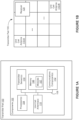
- FIG 2 is an oblique view of a transmitter pad 200, in accordance with some embodiments.
- the transmitter pad 200 is the transmitter pad 100 Figure 1 .
- the transmitter pad 200 includes a housing 202 that defines an internal cavity.
- the internal cavity houses, at a minimum, a plurality of unit cells 110.
- the housing 202 may also house other components 102 of transmitter pad 100 ( Figure 1A ).
- the housing 202 may be formed using a unibody configuration in which some or all of the housing 202 is machined or molded as a single structure or may be formed using multiple structures (e.g., an internal frame structure, one or more structures that form exterior housing surfaces, etc.).
- the housing 202 may be formed of metal (e.g., steel, aluminum, brass, copper, etc.), other suitable materials, or a combination of any two or more of these materials. In some embodiments, at least two portions (e.g., a sidewall and a surface) of the housing 202 are made from different materials having different electromagnetic properties (e.g., permeability and permittivity). In some embodiments, the housing 202 is made entirely of a material that obstructs electromagnetic radiation (e.g., copper, steel, aluminum, etc.).
- the transmitter pad 200 includes a conductive layer or plate 204.
- the conductive plate 204 is part of the housing 202 (e.g., part of the housing's unibody configuration).
- the housing 202 and the conductive plate 204 are separate components of the transmitter pad 200.
- the housing 202 includes an opening at one end of the housing 202 and the conductive plate 204 closes the opening.
- the conductive plate 204 and the housing 202 are made from the same material(s) (e.g., a same type of metal, such as copper, nickel, etc.).
- the conductive plate 204 and the housing 202 are made from at least one different material.
- the transmitter pad 200 also includes a ground or grounding plate (e.g., grounding plate 308, Figure 3A ). As shown in Figure 3A , an insulator (e.g., a dielectric material) may separate the conductive plate 204 from the grounding plate 308.
- a ground or grounding plate e.g., grounding plate 308, Figure 3A .
- an insulator e.g., a dielectric material
- the conductive plate 204 includes a plurality of distinct wireless charging regions that are each associated with at least one unit cell (dotted boxes 206-A and 206-B define respective wireless charging regions).
- a wireless charging region is an area of the conductive plate 204 where wireless charging of receiver 212 (e.g., receiver 120, Figure 1B ) is facilitated due to formation (by respective unit cells 110) of near-field accumulations of electromagnetic energy within one or more of the wireless charging regions.
- the plurality of unit cells covers substantially all of a surface area (e.g., 80% or more) of the conductive plate 204. In this way, a user may wirelessly charge his or her device at various positions on the conductive plate 204. In other words, the user need only place his or her device including a receiver on the transmitter pad and charging will occur without needing to be concerned about the exact location or orientation of the device.
- Each unit cell 206 includes at least two cutouts 208-A and 208-B (e.g., channels/slots extending through the conductive layer or plate 204) that facilitate formation of the near-field accumulations of electromagnetic energy within each of the wireless charging regions.
- cutouts 208-A and 208-B e.g., channels/slots extending through the conductive layer or plate 204 that facilitate formation of the near-field accumulations of electromagnetic energy within each of the wireless charging regions.
- RF power transmission signals 422 Figure 4C
- the RF signals reach the conductive plate 204 and excite a current flow 209 around an edge/perimeter of the conductive plate 204 that is along each of the cutouts 208-A, 208-B associated with the unit cell antenna of the wireless charging region 206-A.
- the accumulations of energy radiate away from the cutouts 208 e.g., an electromagnetic field radiates away from segment 214 and another electromagnetic field radiates away from segment 216).
- These accumulations of energy formed by the RF signals exciting the conductive plate 204 are also referred to herein as “hot zones” or simply “zones.” As noted above, the receiver may harvest energy from these accumulations of energy to deliver power or charge to an electronic device coupled to the receiver.
- each cutout includes a set of dimensions (e.g., a width, a depth (e.g., thickness of the conductive plate 204), and a length). Characteristics of the accumulations of energy (e.g., height, width, degree of concentration, near-field gain, far-field gain, etc.) formed at the cutouts depend, at least in part, on the set of dimensions of the cutouts.
- the set of dimensions of a cutout are carefully selected based on the requirements of the application so that characteristics of the accumulations of energy facilitate proper charging of the receiver 212, e.g., a width of the cutout 208-A is selected so that electromagnetic fields radiating from segments 214 and 216 of the cutout 208-A at least partially cancel each other out (e.g., in the far-field region), thereby minimizing far-field gain, while still creating accumulations of energy that extend far enough above the outer surface of the conductive plate 204 to deliver power to receivers that are embedded within electronic devices (and, since they are embedded, the accumulations need to travel above the surface of the conductive plate 204 to reach these embedded receivers.
- the at least two cutouts in a respective wireless charging region all have a same shape.
- a unit cell within wireless charging region 206-A includes the first cutout 208-A and the second cutout 208-B.
- a shape of the first cutout 208-A mirrors a shape of the second cutout 208-B.
- the first cutout 208-A and the second cutouts 208-B are arranged in an interleaved or interposed fashion (i.e., mated).
- accumulations of energy formed at the first and second cutouts 208-A, 208-B cover a threshold amount of surface area associated with the wireless charging area 206-A (e.g., at least 80% of a surface area of the conductive plate 204 that is associated with wireless charging region 206-A, or some greater (or lesser) amount).
- a threshold amount of surface area associated with the wireless charging area 206-A e.g., at least 80% of a surface area of the conductive plate 204 that is associated with wireless charging region 206-A, or some greater (or lesser) amount.
- far-field components of electromagnetic fields radiating from respective segments of the first cutout 208-A at least partially cancel far-field components electromagnetic fields radiating from respective segment of the second cutout 208-B (e.g., segments that are adjacent to one another). As such, far-field gain is further reduced.
- adjacent unit cells on the conductive plate 204 are rotated relative to one another.
- a first unit cell within wireless charging region 206-A is rotated relative to a second unit cell within wireless charging region 206-B, which is adjacent to the first unit cell.
- the first unit cell and the second unit cell include cutouts arranged in the same interleaved or interposed fashion.
- the cutouts in the first unit cell are arranged along a first axis (e.g., a vertical axis) and the cutouts in the second unit cell are arranged along a second axis (e.g., a horizontal axis), the second axis being perpendicular to the first axis.
- some parts of electromagnetic fields radiating from the second cutout 208-B at least partially cancel some parts of electromagnetic fields radiating from cutout 209 of a unit cell associated with wireless charging region 206-B. As such, far-field gain is further reduced.
- An electronic device 210 is disposed on the outer surface of the conductive plate 204 and is positioned over an additional unit cell (not pictured in Figure 2 ).
- the receiver 212 e.g., receiver 120, Figure 1B
- the transmitter pad 200 e.g., transmitter pad 100, Figures 1A-1B
- the transmitter pad 200 may initiate wireless charging of the receiver 212.
- the transmitter pad 200 detects the receiver by receiving (or exchanging) a communication signal from the receiver 212.
- the transmitter pad 200 detects the presence of the receiver via one or more transmitter sensors 114 ( Figure 1A ).
- a light sensor of the transmitter pad 200 may detect a change in light inside the internal cavity of the housing 202 when the electronic device is positioned over one of the cutouts in the conductive plate 204.
- an infrared sensor of the transmitter pad 200 may detect a change in temperature at the conductive plate 204 when the electronic device is positioned over one of the cutouts in the conductive plate 204.
- Other types of sensors and sensor data may be used to detect the receiver 212.
- cutouts 208 are shown with a particular shape (e.g., a U or horseshoe shape), the cutouts may have other suitable shapes (e.g., different unit cell antennas within one transmitter pad could have different shapes).
- a size of the electronic device 210 and the receiver 212 relative to a size of the unit cells 206 shown in Figure 2 is merely illustrative (e.g., the unit cells may be smaller (or larger) relative to a size on the electronic device 210 and the receiver 212).
- a respective unit cell may have dimensions of approximately 35 mm by 35 mm.
- a transmitter pad that includes a 2 by 2 arrangement of unit cells may have dimensions of approximately 70 mm by 70 mm.
- the transmitter pad may include a 3 by 3 arrangement of unit cells, and the transmitter pad may therefore have dimensions of approximately 105 mm by 105 mm.
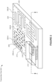
- FIGS 3A-3D show cross-sectional views of the transmitter pad 200 (taken along the line A-A' of Figure 2 ), in accordance with some embodiments. Cross-sectional hashing has been removed from antennas 306 and feed elements 307 for clarity.
- the conductive plate 204 includes a plurality of cutouts (e.g., cutout 302-A) extending through the conductive plate 204 (e.g., extending from an outer surface of the conductive plate 204 through to an inner surface of the conductive plate 204).
- the conductive plate 204, and in turn the plurality of cutouts, have a thickness of T1.
- the transmitter pad 200 also includes an insulator 304, which is responsible, at least in part, for projecting the accumulations of energy at different distances above the conductor plate 204.
- the insulator 304 separates respective feeding elements 307-A and 307-B from an inner surface of the conductive plate 204.
- the insulator 304 is sandwiched between the conductive plate 204 and the grounding plate 308.
- the insulator 304 has a thickness of T2.
- the thickness (T1) of the conductive plate 204 is greater than the thickness (T2) of the insulator 304, or vice versa.
- the thickness (T1) of the conductive plate 204 is the same as the thickness (T2) of the insulator 304.
- the thickness (T2) of the insulator 304 is selected based, at least in part, on the operating frequency.
- the thickness (T2) of the insulator 304 may range from 0.03 ⁇ to 0.5 ⁇ of the operating frequency.
- the thickness (T2) of the insulator 304 when operating at a frequency of 400 MHz, can range from approximately 0.0225 meters (i.e., 22.5 mm) to approximately 0.375 meters (i.e., 375 mm) and when operating at a frequency of 60 GHz, the thickness (T2) of the insulator 304 can range from approximately 0.00015 meters (i.e., 0.15 mm) to approximately 0.0025 meters (i.e., 2.5 mm).
- the thickness (T2) of the insulator 304 can vary from application to application and the examples provided above are simply used to provide context. Therefore, in some embodiments, the thickness (T2) of the insulator 304 can range from approximately 0.15 mm to approximately 375 mm.
- the thickness (T2) of the insulator 304 may modify one or more characteristics of the accumulations of energy (e.g., height, width, degree of concentration, near-field gain, far-field gain, resonance frequency, etc.) radiating from the conductive plate 204. For example, when the insulator has a first thickness (T2'), the accumulations of energy may extend above the outer surface of the conductive plate 204 to a first height and when the insulator has a second thickness (T2”), the accumulations of energy may extend above the outer surface of the conductive plate 204 to a second height, the second height being different from the first height. Accordingly, the thickness (T2) of the insulator 304 may influence an overall efficiency of the electromagnetic fields radiating from the conductive plate 204.
- T2' first thickness
- T2 second thickness
- the thickness (T2) of the insulator 304 may influence an overall efficiency of the electromagnetic fields radiating from the conductive plate 204.
- the thickness of the conductive plate 204 may also be selected to influence formation of the accumulations (e.g., the thickness, T1, of the conductive plate 204 is selected to help influence (i) cancellation of parts of electromagnetic fields in the far-field region and (ii) accumulations of energy extend far enough in the near-field region above an outer surface of the conductive plate 204 to deliver power to the receiver 212).
- the thickness, T1 of the conductive plate 204 is selected to help influence (i) cancellation of parts of electromagnetic fields in the far-field region and (ii) accumulations of energy extend far enough in the near-field region above an outer surface of the conductive plate 204 to deliver power to the receiver 212).
- the insulator 304 is air.
- the insulator 304 is a dielectric material (e.g., a polymer, a fiber reinforced polymer, glass, etc.) disposed inside the internal cavity of the housing 202.
- the thickness (T2) of the insulator 304 can influence one or more characteristics of the accumulations of energy.
- using a first type of insulator over a second type of insulator may also influence one or more characteristics of the accumulations of energy.
- the insulator 304 supports the conductive plate 204 (e.g., the conductive layer is formed on the insulating layer and the cutouts are etched from the conductive layer and through to the insulator).
- the transmitter pad 200 includes a first unit cell 305-A and a second unit cell 305-B (separated by dashed line).
- the first unit cell 305-A includes a first feed element 307-A and the second unit cell 305-B includes a second feed element 307-B.
- the first and second unit cell antennas 305 may be an example of the one or more unit cell antennas 110 ( Figures 1A-1B ).
- the first and second feed elements 307 are separated from an inner surface of the conductive plate 204 by a distance (D). In some embodiments, however, the first and second antennas are separated from the inner surface of the conductive plate 204 by different distances.
- Variations in the distance (D) may modify one or more characteristics of the accumulations of energy (e.g., height, width, degree of concentration, near-field gain, control of far-field gain, etc.) radiating from the conductive plate 204.
- the distance (D) is less than the thickness (T2) of the insulator 304.
- the distance (D) is less than the thickness (T2) of the insulator 304 by a threshold amount. Put another way, a ratio between the distance (D) and the thickness (T2) of the insulator 304 satisfies a predefined range.
- the predefined range may limit the ratio of (D) / (T2) from 0.05 ⁇ to 0.8 ⁇ , i.e., 0.05 ⁇ ⁇ (D) / (T2) ⁇ 0.8 ⁇ .
- the thickness (T2) of the insulator 304 can range from approximately 0.15 mm to approximately 375 mm, depending on the operating frequency of the transmitter pad 200.
- the distance (D) can range from approximately 0.0075 mm (e.g., when operating at a frequency of 60 GHz) to approximately 300 mm (when operating at a frequency of 400 MHz), in light of the predefined range limiting the ratio of (D) / (T2) from 0.05 ⁇ to 0.8 ⁇ .
- the first and second feed elements 307 may be at least partially encapsulated by the dielectric material. In doing so, the first and second feed elements 307 (and the other antennas of the transmitter pad 200) are further supported, and as such, the durability of the transmitter pad 200 is increased (e.g., the insulator better absorbs impact forces, such as when the transmitter pad 200 is dropped). Additionally, interference between the first and second feed elements 307 (and other feed elements) is substantially reduced when the feed elements 307 are at least partially encapsulated by the dielectric material (i.e., the feed elements 307 are electrically isolated from one another). In light of this arrangement, an overall efficiency of the transmitter pad 200 is increased.
- the transmitter pad 200 includes a metal patch element 306 for each antenna element.
- the feed element 307 drives the corresponding patch element 306.
- the first patch element 306-A is driven by a first feed element 307-A
- the second patch element 306-B is driven by a second feed element 307-B.
- the feed element 307 may be made from any suitable material known by those skilled in the art (e.g., aluminum, copper, etc.).
- the transmitter pad 200 includes a ground or grounding layer or plate 308.
- the grounding plate 308 forms a bottom surface of the housing 202 ( Figure 2 ). Alternatively, in some embodiments, the grounding plate 308 is placed on top of the bottom surface inside the housing 202.
- the grounding plate 308 may be formed out of the same material as the housing 202 or may be formed out of a different material.
- the grounding plate 308 includes a hole (e.g., a via) allowing the feed element (e.g., feed element 307-A) to pass through the grounding plate 308.
- the feed element does not pass through the grounding plate 308 but instead connects to the antenna element from some other direction (e.g., the side).
- the grounding plate 308 acts as a reflector such that RF power transmission signals cannot pass through the grounding plate 308 and are reflected back towards respective cutouts of a unit cell instead.
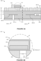
- Figure 3B is a close-up cross-sectional view of the electronic device 210 placed on the conductive surface 204.
- the electronic device 210 and in turn the receiver 212, are positioned over cutout 302-B (e.g., one of the plurality of cutouts in the conductive plate 204).
- cutout 302-B e.g., one of the plurality of cutouts in the conductive plate 204.
- the first feed 307-A transmits a plurality of RF power transmission signals towards the inner surface of the conductive plate 204
- at least some of the RF power transmission signals of the plurality of RF power transmission signals excite a current to flow around the cutout 302-B and thereby cause accumulations of electromagnetic energy to form above the cutout 302-B within a near-field distance of the conductive plate 204.
- the receiver 212 may then harvest energy from the accumulation of energy formed above the cutout 302-B.
- the electronic device 210 includes a sidewall 322 and an internal cavity 324 housing the receiver 212. As shown, the receiver 212 is not placed directly on an outer surface of the conductive plate 204. Instead, the receiver 212 is separated from the outer surface of the conductive plate 204 by a distance "X" (i.e., a thickness of the sidewall 322). Accordingly, the transmitter pad 200 may adjust one or more characteristics (e.g., waveform characteristics, such as phase, gain, amplitude, frequency, etc.) of power waves transmitted by feed element 307-A to ensure that an accumulation of energy extends above the outer surface of the conductive plate 204 by at least the distance X. In some embodiments, the transmitter pad 200 adjusts one or more characteristics of the power waves so that the accumulation of energy extends past the distance X by a predefined amount, thereby ensuring that the receiver 212 can harvest energy from the accumulation of energy.
- characteristics e.g., waveform characteristics, such as phase, gain, amplitude, frequency, etc.
- the transmitter pad 200 adjusts the one or more characteristics of the power waves (e.g., RF power transmission signals 422, Figure 4C ) after detecting a presence of the receiver 212.
- the transmitter pad 200 may detect a presence of the receiver 212 using the example techniques described above.
- the transmitter pad 100 adjusts the one or more characteristics of the power waves after receiving one or more communication signals from the receiver 212.
- data contained within the one or more communication signals may indicate that the receiver 212 is separated from the first feed 307-A by a particular distance.
- the transmitter pad 200 may determine the separation distance based on signal strength of the one or more communication signals, triangulation, and/or response time (e.g., receiver 212 timestamps a communication signal when sent which is then compared against a timestamp of the communication signal when it is received at the transmitter pad 200).
- the transmitter pad 200 determines the separation distance using two or more forms of data (e.g., signal strength in combination with a thermal imaging data, or some other combination). Using the separation distance, the transmitter pad 200 may determine a thickness of the sidewall 322 of the electronic device 210 (e.g., subtract fixed distance between feed 307-A and the outer surface of conductive plate 204 from the separation distance to obtain distance "X").
- the transmitter pad 100 adjusts the one or more characteristics of the power waves by considering data obtained from the receiver 212, data obtained by the transmitter sensors, the set of dimensions of the cutout(s), and an arrangement of the cutouts.
- Figure 3C is another cross-sectional view 330 of the transmitter pad 200 (taken along the line A-A' of Figure 2 ), in accordance with some embodiments.
- the electronic device 210 and the receiver 212 are not shown in Figures 3C-3D for ease of illustration and discussion.
- some other references, which are included in Figure 3A are not included in Figures 3C-3D for clarity.
- the housing 202 includes four sidewalls (e.g., sidewalls 332-A, 332-B, and so on), a bottom surface 334, and an opening defined opposite the bottom surface 334.
- the opening is configured to receive the conductive plate 204.
- the conductive plate 204 is coupled to the four sidewalls of the housing 202 such that the conductive plate 204 closes the opening.
- the bottom surface 334 is the grounding plate 308 ( Figure 3A ).
- the grounding plate 308 is disposed on top of the bottom surface 334 of the housing, as discussed above.
- the bottom surface 334 includes one or more holes (e.g., vias) allowing one or more feeds (e.g., feed element 307-A) to pass through the housing 202.
- an antenna type may dictate a separation distance of the antenna from an inner surface of the conductive plate 204.
- the first and second feeds 307-A, 307-B are separated from the inner surface of the conductive plate 204 by a first distance (D).
- the first and second feed elements 307-A, 307-B may feed metal patches 306-A and 306-B, respectively (e.g., the feed and metal patches form respective antennas of a first type, patch antennas, that excite the cutouts located above).
- the feed elements 307-A, 307-B may feed various other antenna types (e.g., monopole, dipole, magnetic loops, multilayer parasitic-fed antennas, etc.).
- first and second feed elements 336-A, 336-B are separated from the inner surface of the conductive plate 204 by a second distance (J), which is less than the first distance (D).
- the first and feed elements 336-A, 336-B are a second type of antenna (e.g., a monopole antenna). Accordingly, depending on the circumstances (e.g., design restrictions such as a height restriction of the transmitter pad 200), one type of antenna may be used over another type of antenna.
- a complimentary relationship between the cutouts and the feed elements 336-A, 336-B improves performance of the transmitter pad 200.
- An example of the "complimentary relationship" includes a cutout defined through the conductor plate 204 paired with a patch (e.g., microstrip printed type of feed element) (as shown in Figure 3A ).
- a patch e.g., microstrip printed type of feed element
- One other example includes a wire conductor on an outer surface of the conductive plate 204 surface paired with a slot style feed. It should be noted that the example above is merely illustrative and the result may be opposite, depending on the circumstances.
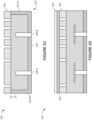
- Figure 3D is another cross-sectional view 340 of the transmitter pad 200 (taken along the line A-A' of Figure 2 ), in accordance with some embodiments.
- the transmitter pad 200 may include one or more additional layers disposed on top of the conductive plate 204.
- a first additional layer 342 is a dielectric material (e.g., a plastic layer, a glass layer, etc.) that separates the electronic device 212 from the outer surface of the conductive plate 204. Because the first additional layer 342 is a dielectric layer, it does not alter an accumulation of energy formed at a respective cutout.
- the transmitter pad 200 has to compensate for a thickness of the first additional layer 342 because a separation distance (i.e., distance "X," Figure 3B ) between the receiver 212 and the antenna is increased when the first additional layer 342 is included.
- the first additional layer 342 acts as a "lens,” meaning it increases a degree of concentration (e.g., focuses) of the accumulations of energy formed near the cutouts. Accordingly, the first additional layer 342 may improve isolation at specific locations relative to the center of the unit cell (e.g., reduce radiation to neighboring unit cells).
- the first additional layer 342 uniformly distributes energy across the outer surface of the conductive plate 204. As a result, gaps (i.e., "cold zones”) between adjacent accumulations of energy may be minimized, or even eliminated.
- the transmitter pad 200 includes a second additional layer 344 disposed on top of the first additional layer 342.
- the second additional layer 344 may be a conductive material such as aluminum or copper.
- the second additional layer 344 is another conductive plate, similar to the conductive plate 204.
- the second additional layer 344 is deposited (e.g., printed, painted, etc.) onto the first additional layer 344.
- the transmitter pad 200 has to compensate for a thickness of the second additional layer 344 because a separation distance (i.e., distance "X," Figure 3B ) between the receiver 212 and the antenna is increased when the second additional layer 344 is included.
- the second additional layer 344 alters formation of one or more accumulations of energy formed at a respective cutout.
- the second additional layer 344 may increase a concentration and/or may adjust a position of the accumulation of energy formed at the respective cutout (i.e., may offset a position).
- the second additional layer 344 can be used to merge one or more portions of a first accumulation of energy with one or more portions from a second (and perhaps a third) accumulation of energy (i.e., uniformly distribute energy across the outer surface of the conductive plate 204). In this way, gaps (i.e., "cold zones") between adjacent accumulations of energy may be minimized, or even eliminated.
- the second additional layer 344 further improves the benefits discussed above with regards to the first additional layer 344.
- Figures 4A-4C show a unit cell and accumulations of energy that form at respective cutouts of the unit cell, in accordance with some embodiments.
- Figure 4A is a top view of a unit cell 400 (e.g., unit cell 110-A, Figure 1 ).
- the unit cell 400 includes a conductive plate 402 (e.g., conductive plate 204, Figure 2 ) having first and second cutouts 404 (e.g., channels, slots, etc.) defined through the conductive plate 402.
- the unit cell 400 includes a feed element 406 (e.g., feed 307-A, Figure 3A ) located beneath the conductive plate 402 (e.g., located in an internal cavity defined by housing 202, Figure 2 ).
- the feed element 406 is shown to be centered in the unit cell 400, in some embodiments, the feed element 406 is not centered (or may be centered about a first axis but not centered about a second axis). Placing the feed element 406 at different positions can influence a distribution of the accumulations of energy (e.g., a first position may create a more uniform distribution and a second position may create a more focused distribution).
- each of the first and second cutouts 404 includes a plurality of portions 408 (also referred to herein as cutout portions). Portions of a respective cutout may be arranged in numerous ways.
- the first cutout 404-A includes a first portion 408-A that is perpendicular (e.g., orthogonal) to a second portion 408-B, and a third portion 408-C that is also perpendicular to the second portion 408-B.
- the second cutout 404-B includes similar portions (not labeled).
- first portion 408-A may be perpendicular to the second portion 408-B
- third portion 408-C may also be perpendicular to the second portion 408-B, but may extend downwards (instead of upwards as shown in Figure 4A ).
- a shape of the first cutout 404-A mirrors a shape of the second cutout 404-B (e.g., a horseshoe shape).
- the first cutout 404-A interleaves or interposes with the second cutout 404-B. This arrangement minimizes gaps between the first and second cutouts (e.g., minimized gaps between respective portions of the first and second cutouts 404), which results in gaps between adjacent accumulations of energy also being minimized.
- the complimentary natural of the cutouts 404 e.g., the interlocking arrangement
- also minimizes far-field gain of the unit cell 400 and (ii) reduces interference with other devices positioned on other unit cells.
- far-field electromagnetic fields from a respective portion of the cutout 404-A is at least partially cancelled out (as discussed above with reference to Figure 2 ) by far-field electromagnetic fields from portions that are adjacent to the respective cutout.
- far-field gain of electromagnetic radiation is further minimized between each of the cutouts.
- each of the first and second cutouts 404 has a total length that is at least as large as a wavelength of a respective RF power transmission signal transmitted by the transmitter pad (e.g., transmitted by antenna element 406). As such, at least in some embodiments, a length of each portion of the cutouts 404 is less than the wavelength of the respective RF power transmission signal transmitted by the transmitter pad.
- the second cutout 404-A includes first, second, and third portions 408-A, 408-B, and 408-C, respectively, that each have a length of "X," which is less than the wavelength.
- the total length of the cutout 404-A is at least as large as the wavelength.
- the length of "X" is half (or approximately half) the wavelength of the respective RF power transmission signal transmitted by the transmitter (e.g., ⁇ /2). In some embodiments, the length of "X" is some other percentage of the wavelength.
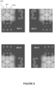
- Figure 4B is a top view 410 of the unit cell 400 showing accumulations of energy formed upon transmission of a plurality of RF power transmission signals by the feed element 406, in accordance with some embodiments.
- multiple accumulations of energy e.g., accumulation of energy 412
- the number of accumulations corresponds to the number of portions in a respective cutout.
- the first and second cutouts 404 each include three portions (e.g., first portion 408-A, second portion 408-B, and third portion 408-C).
- the first and second cutouts 404 each include three accumulations of energy.
- any number of accumulations of energy may be created depending on a design of a respective cutout (e.g., a cutout having say, 10 perpendicular portions, facilitates creation of 10 accumulations of energy).
- a length of a respective portion dictates whether an accumulation of energy forms at the respective portion, and also dictates characteristics of the electromagnetic field radiating from the respective portion (e.g., an amount of energy present in the accumulation of energy).
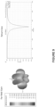
- Figure 4C is a cross-sectional view 420 (taken along line C-C' of Figure 4B ) of the unit cell 400 during transmission of the plurality of RF power transmission signals 422 by the feed element 406, in accordance with some embodiments.
- transmission of the plurality of RF power transmission signals 422 by the feed element 406 causes conduction of a current along a perimeter of the cutouts 404 located above, thereby causing a plurality of NF accumulations of energy 412-A - 412-D to form at the first and second cutouts 404.
- the plurality of accumulations of energy 412-A - 412-D extends above the conductive plate 402 by a distance "Y.”
- the distance “Y” is greater than the separation distance "X” discussed above with reference to Figure 3B (e.g., the distance "X” concerns a distance between the receiver 212 and the outer surface of the conductive 204). Because of this, each of the plurality of accumulations of energy 412-A - 412-D can reach a receiver placed on top of the conductive plate 402, thereby facilitating wireless charging of the receiver.
- the plurality of accumulations of energy 412-A - 412-D extends approximately 1 to 5 millimeters above the outer surface of the conductive plate 402. For example, if a receiver is separated from the outer surface of the conductive plate 402 by 2 millimeters, then the plurality of accumulations of energy 412-A - 412-D may extend above the outer surface of the conductive plate 402 by 2.1 to 5 millimeters.
- a processor 104 of the transmitter pad 100 modifies one or more characteristics of the plurality of RF power transmission signals 422 to increase (or decrease) the distance "Y.”
- a variety of variables may be manipulated to cause formation of NF accumulations of energy at various distances from the conductive plate 402, and these variables include a thickness of the conductive plate 402, a thickness of the insulator 414 (e.g., insulator 304, Figure 3A ), a width of the cutout, a length of a portion, and the type of antenna may also increase (or decrease) the distance "Y," depending of types of devices that will be charged using a particular transmitter pad that includes a plurality of unit cells.
- Figures 5A-5B show a unit cell and accumulations of energy that form at a single cutout of the unit cell, in accordance with examples that are out of the scope of the invention.
- Figure 5A is a top view of a unit cell 500 (e.g., unit cell 1 10-A, Figure 1B ).
- the unit cell 500 includes a conductive plate 502 (e.g., conductive plate 204, Figure 2 ) having a cutout 504 (e.g., channel/slot).
- the unit cell 500 includes a feed element 506 (e.g., feed element 307-A, Figure 3A ) located beneath the conductive plate 502 (e.g., located in an internal cavity defined by housing 202, Figure 2 ).
- the feed element 506 is shown to be centered in the unit cell 500, in some embodiments, the feed 506 is not centered (or may be centered about a first axis but not a second axis).
- the cutout 504 has a total length that is at least as large as a wavelength of a respective RF power transmission signal transmitted by the transmitter (e.g., transmitted by antenna element 506).
- the cutout 504 includes a plurality of portions (e.g., each vertical and horizontal section of the cutout 504).
- a length for each portion of the cutout 504 is less than a wavelength of the respective RF power transmission signal transmitted by the transmitter pad (e.g., transmitter pad 200, Figure 2 ).
- a length of each of the plurality of portions is the same (e.g., ⁇ /2).
- a first set of portions of the plurality of portions has a first length and a second set of portions of the plurality of portions has a second length, the second length being greater than the first length.
- the first length is a length that facilitates creation of accumulations of energy (e.g., ⁇ /2) and the second length is a length that does not facilitate creation of accumulations of energy (e.g., ⁇ ).
- FIG. 5B is a top view 510 of the unit cell 500 showing accumulations of energy formed after transmission of a plurality of RF power transmission signals by the antenna element 506, in accordance with some examples that are out of the scope of the invention.
- Each of the plurality of accumulations of energy (e.g., accumulation of energy 508) forms along a portion of the cutout 504.
- each respective portion of the cutout 504 has a corresponding accumulation of energy formed at the respective portion.
- one or more portions of the cutouts 504 lack a corresponding accumulation of energy formed at the respective portion (e.g., when a length of the respective portion does not facilitate creation of an accumulation of energy).
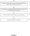
- Figure 6 is a flow diagram showing a method of wireless power transmission for forming one or more accumulations of RF energy at a near-field distance with minimal far-field gain.
- Operations (e.g., steps) of the method. 600 may be performed by a near-field charging pad (e.g., transmitter pad 100, Figures 1A-1B ; transmitter pad 200, Figure 2 ) or by one or more components thereof (e.g., an RF power transmission signals generation module, a characteristic selection module, and/or a beacon transmitting module).
- a near-field charging pad e.g., transmitter pad 100, Figures 1A-1B ; transmitter pad 200, Figure 2
- one or more components thereof e.g., an RF power transmission signals generation module, a characteristic selection module, and/or a beacon transmitting module.
- At least some of the operations shown in Figure 6 correspond to instructions stored in a computer memory or computer-readable storage medium (e.g., memory 106 of the transmitter pad 100, Figure 1A ).
- the method 600 includes providing (602) a near-field antenna (e.g., unit cell 400, Figure 4 ; unit cell 500, Figure 5 ) that includes a conductive plate (e.g., conductive plate 204, Figure 2 ) having (i) first and second opposing planar surfaces (e.g., an inner surface and an outer surface) and (ii) at least two cutouts (e.g., cutouts 404-A and 404-B, Figure 4 ; cutout 504, Figure 5A ) extending through the conductive plate from the first surface to the second surface.
- a near-field antenna e.g., unit cell 400, Figure 4 ; unit cell 500, Figure 5
- a near-field antenna e.g., unit cell 400, Figure 4 ; unit cell 500, Figure 5
- a near-field antenna e.g., unit cell 400, Figure 4 ; unit cell 500, Figure 5
- a near-field antenna e.g., unit cell 400, Figure 4 ; unit cell 500,
- the near-field antenna further includes a feed element (e.g., feed element 307, Figure 3A ) separated from the first surface of the conductive plate via an insulator (e.g., insulator 304, Figure 3A ).
- the feed element is at least a component of a patch antenna, where the insulator is disposed between the feed element and the conductive plate.
- the feed element is a component of a patch antenna that is at least partially encapsulated within the insulator.
- the conductive plate is a plate specific to the unit cell (i.e., a distinct and separate plate). Alternatively, in some embodiments, the conductive plate extends to one or more adjacent unit cells.
- the near-field antenna further includes another insulator that separates the feed element from a grounding plate (e.g., grounding 308, Figure 3A ).
- the insulator separates the feed element from the grounding plate.
- the conductive plate is a conductive layer deposited on a surface of the insulator (e.g., the insulator is a rigid polymer substrate and the conductive layer is deposited thereon).
- the insulator is a dielectric layer that is deposited on the first surface of the conductive plate.
- the insulator is selected from the group consisting of: a polymer, a fiber reinforced polymer, glass, and air. In some embodiments, a thickness of the insulator is greater than a thickness of the conductive plate, or vice versa.
- a first cutout of the at least two cutouts forms a first meandering line pattern and a second cutout of the at least two cutouts forms a second meandering line pattern.
- the first and second meandering line patterns are the same meandering line pattern (i.e., a shape of the first meandering line pattern mirrors a shape of the second meandering line pattern).
- a first cutout 404-A forms the first meandering line pattern
- the second cutout 404-B forms the second meandering line pattern.
- the first and second meandering line patterns are different meandering line patterns.
- a line pattern is considered a meandering line pattern when the line pattern includes at least one direction change.
- the at least one direction change is a perpendicular direction change.
- the at least one direction change is some other angular direction change.
- the first meandering line pattern is rotated with respect to the second meandering line pattern (e.g., rotated 180 degrees).
- a shape of the first meandering line pattern may be disposed in a first direction and a shape of the second meandering line pattern may be disposed in a second direction, which is opposite to the first direction.
- the first cutout 404-A i.e., the first meandering line pattern
- the second cutout 404-B i.e., the second meandering line pattern
- the method 600 further includes causing (604) the feed element to direct a plurality of RF power transmission signals (e.g., RF power transmission signals 422, Figure 4C ) towards the conductive plate (e.g., towards an inner surface of the conductive plate 204, Figure 2 ).
- a plurality of RF power transmission signals e.g., RF power transmission signals 422, Figure 4C
- the plurality of RF power transmission signals is transmitted at a frequency selected from the group consisting of: 5.8 GHz, 2.4 GHz, and 900 MHz.
- the transmitter pad 200 detects a receiver on the conductive plate (e.g., a user places an electronic device 210, which houses the receiver 212, on an outer surface of the conductive plate 204, thereby putting the receiver within a threshold distance of the wireless charging region 206-A, Figure 2 ).
- the feed element receives the one or more RF power transmission signals from a power amplifier in response to determining that a receiver is placed within the threshold distance of the outer surface.
- the threshold distance is a predetermined threshold distance (e.g., the predetermined threshold distance is stored in memory 106 of the transmitter pad 100, Figure 1A ).
- the transmitter pad 200 detects the receiver using one or more sensors (e.g., transmitter sensors 114, Figure 1A ). Alternatively or in addition, in some embodiments, the transmitter pad 200 detects the receiver by receiving (or exchanging) one or more communication signals from (or with) the receiver (e.g., receiving the one or more communication signals via the communications component(s) 112, Figure 1A ). For example, a signal strength level associated with the one or more communication signals received by a processor 104 ( Figure 1A ) connected to the near-field antenna may indicate that the receiver is within the threshold distance of the outer surface. Detecting the receiver is discussed in further detail above with reference to Figures 2 and 3A-3B .
- the method 600 further includes receiving (606), at the conductive plate, the plurality of RF power transmission signals from the feed element.
- receiving the plurality of RF power transmission signals from the feed element causes a current to flow (e.g., current flow 209, Figure 2 ) along an edge/ perimeter of the conductive plate defined by the one or more cutouts.
- the method 600 further includes radiating (608), through the at least two cutouts, at least some of the plurality of RF power transmission signals so that RF energy from the plurality of RF power transmission signals accumulates within a near-field distance of the conductive plate to create at least two distinct zones of accumulated RF energy (e.g., accumulations of energy 412-A - 412-D, Figure 4C ) at each of the at least two cutouts.
- the at least two distinct zones of accumulated RF energy at each of the at least two cutouts are defined based, at least in part, on (i) a set of dimensions defining each of the at least two cutouts and (ii) an arrangement of the at least two cutouts.
- the set of dimensions defining each of the at least two cutouts may include: a thickness of the conductive plate, a width of the cutout, a shape of the cutout, a length of the cutout, and a number of portions (e.g., segments) of the cutout.
- the arrangement of the at least two cutouts minimizes gaps between adjacent zones of accumulated RF energy.
- one or more adjacent zones of accumulated RF energy may substantially merge, thereby eliminating gaps between the zones of accumulated RF energy.
- the at least two distinct zones cover at least 80% of a surface area of the second surface of the conductive plate.
- the at least two distinct zones cover at least 90% of the surface area of the second surface of the conductive plate.
- a degree of coverage of the surface area is based, at least in part, on (i) the set of dimensions defining each of the at least two cutouts and (ii) the arrangement of the at least two cutouts (e.g., arrangement in a given unit cell and also an arrangement of cutouts between adjacent unit cells).
- a respective cutout of the at least two cutouts has a respective length that is at least as large as a wavelength of a respective RF power transmission signal of the plurality of RF power transmission signals.
- the respective cutout includes, at least, a first portion defined in a first direction (e.g., first portion 408-A, Figure 4A ) and a second portion (e.g., second portion 408-B, Figure 4A ) defined in a second direction, the second direction being orthogonal to the first direction. Moreover, a first of the at least two distinct zones of accumulated RF energy is created at the first portion and a second of the at least two distinct zones of accumulated RF energy is created at the second portion.
- a first direction defined in a first direction e.g., first portion 408-A, Figure 4A
- a second portion e.g., second portion 408-B, Figure 4A
- the respective cutout further includes a third portion defined in the first direction (e.g., third portion 408-C, Figure 4A ) or some other direction.
- the third portion mirrors the first portion, such that the respective cutout forms a horseshoe shape.
- the third portion extends away from the first and second portions, such that the respective cutout forms an "S" shape.
- a third distinct zone of accumulated RF energy is created at the third portion.
- the respective cutout may further include additional portions defined in various directions.
- the at least two distinct zones of accumulated RF energy extend no more than 5 millimeters above the second surface of the conductive plate (or some greater (or lesser) amount). In this way, far-field gain of the near-field charging pad is controlled and potential interference with other devices (or other metallic objects) located in proximity to the near-field charging pad is significantly reduced, and in some circumstances, completely eliminated.
- the near-field antenna is a first near-field antenna (e.g., a unit cell associated with wireless charging region 206-A, Figure 2 ) and is part of a near-field charging pad (e.g., transmitter pad 200, Figure 2 ) that also includes, at least, a second near-field antenna (e.g., a unit cell associated with wireless charging region 206-B, Figure 2 ) that is positioned adjacent to the first near-field antenna within the near-field charging pad.
- respective cutouts associated with the second near-field antenna are rotated relative to the at least two cutouts associated with the first near-field antenna.
- the second near-field antenna (e.g., a unit cell associated with wireless charging region 206-B, Figure 2 ) may be rotated (e.g., 90 degrees) relative to the first near-field antenna (e.g., a unit cell associated with wireless charging region 206-A, Figure 2 ), or vice versa.
- Rotating adjacent unit cells, and in turn the cutouts defined therein helps to further increase control over far-field gain, and ensure that the far-field gain is substantially reduced for the near-field charging pad as a whole.
- gaps between adjacent accumulations of energy e.g., unit cell to unit cell
- FIG 7 is a flow diagram showing a method of fabricating a near-field antenna, in accordance with some embodiments.
- the near-field antenna may be an example of a single unit cell (e.g., unit cell 1 10-A, Figure 1 ; unit cell 400, Figure 4 ; etc.).
- the method 700 includes selecting (702) a set of dimensions for at least two cutouts (e.g., cutouts 404-A and 404-B, Figure 4A ) to be defined through a conductive plate (e.g., conductive plate 402, Figure 4A ) of the near-field antenna, the conductive plate having opposing first (e.g., an inner) and second (e.g., an outer) planar surfaces. Dimensions for the at least two cutouts are discussed in further detail above.
- the method 700 further includes forming (704) the at least two cutouts through the first and second surfaces of the conductive plate in a predefined arrangement (e.g., in an interlocking arrangement as shown in Figure 4A ), each of the at least two cutouts having the set of dimensions.
- forming the one or more cutouts includes milling (e.g., CNC milling) the at least two cutouts, laser etching the one or more cutouts, chemically etching the one or more cutouts, or some other method known by those skilled in the art. It should be noted that a cutout itself may be formed in a "predefined arrangement," e.g., the cutout 504 is formed in a predefined arrangement ( Figure 5 ).
- the method 700 further includes coupling (706) an insulator (e.g., insulator 304, Figure 3A ) to the first surface (e.g., the inner surface) of the conductive plate.
- the insulator may be mechanically and/or chemically (e.g., using an adhesive) fastened to the first surface of the conductive plate.
- the insulator supports one or more regions of the conductive plate.
- the insulator is coupled to the first surface (e.g., the inner surface) of the conductive plate prior to forming the one or more cutouts through the conductive plate (or the insulator is deposited on the first surface of the conductive plate prior to forming the one or more cutouts).
- forming (704) the one or more cutouts through the conductive plate includes, e.g., milling through the outer surface of the conductive plate to a surface of the insulator coupled to the inner surface of the conductive plate.
- the method 700 further includes coupling (708) a feed element to the insulator.
- the feed element is mechanically and/or chemically (e.g., using an adhesive) fastened to the insulator.
- the feed element is embedded, at least partially, within the insulator. It should be noted that step 708 may be skipped in those embodiments where the insulator is air.
- the feed element may be coupled to some other structure of the near-field antenna (e.g., a portion of the housing 202, Figure 2 ).
- the insulator is a first insulator
- the method further includes coupling a second insulator to the feed element.
- the first insulator may be coupled to a top portion of the feed element and the second insulator may be coupled to a bottom portion of the feed element.
- the feed element may be mechanically and/or chemically (e.g., using an adhesive) fastened to the second insulator.
- the feed element is embedded, at least partially, within the second insulator.
- the feed element is configured to direct a plurality of RF power transmission signals towards the conductive plate and at least some of the RF power transmission signals of the plurality of RF power transmission signals radiate through the Z F at least two cutouts and accumulate within a near-field distance of the conductive surface to create at least two distinct zones of accumulated RF energy at each of the at least two cutouts.
- the at least two distinct zones of accumulated RF energy at each of the at least two cutouts are defined based, at least in part, on (i) a set of dimensions defining each of the at least two cutouts and (ii) an arrangement of the at least two cutouts. Forming the accumulations of energy is discussed in further detail above with reference to Figures 2 - 5B .
- the steps of the method 700 may be repeated such that additional near-field antennas are fabricated.
- the method 700 further includes forming an array of near-field antennas (e.g., an array of unit cell antennas 110-A - 110-N, as shown in Figure 1B ).
- the conductive plate is a continuous plate associated with each near-field antenna in the array of near-field antennas.
- each near-field antenna includes a distinct conductive plate.
- the array of near-field antennas may be interconnected via busing (e.g., communication bus 108, Figure 1A ) and may further be connected to one or more processors (e.g., processor(s) 104 of transmitter pad 100, Figure 1A ).
- busing e.g., communication bus 108, Figure 1A
- processors e.g., processor(s) 104 of transmitter pad 100, Figure 1A .
- the array of near-field antennas is disposed in a housing (e.g., housing 202, Figure 2 ). In this way, leakage of RF power transmission signals (e.g., via sidewalls) in substantially reduced, and even eliminated.
- Figure 8 shows various power distributions (e.g., accumulations of energy) formed on a transmitter pad, in accordance with some embodiments.
- Figure 8 shows concentrations of accumulations of energy 802 on a transmitter pad (e.g., transmitter pad 100, Figures 1A-1B ) having four unit cells (e.g., unit cell 400, Figure 4A , unit cell 500, Figure 5A ), and each unit cell is being sequentially activated (e.g., activated meaning a feed element for a unit cell starts transmitting RF power transmission signals).
- the accumulations of energy 802 substantially cover a surface area of the unit cell 801.
- the surface area of the unit cell 801 has minimal cold zones 804. This results from, as discussed above, the set of dimensions defining each of the at least two cutouts and an arrangement of the at least two cutouts.
- the accumulations of energy 802 are substantially limited to the currently activated unit cell (i.e., electromagnetic radiation created at unit cell 801 does not substantially radiate to neighboring unit cells).
- Figure 9 is a graph that shows an example radiation pattern for a unit cell antenna that includes at least two cutouts, as compared to a radiation pattern for an isotropic antenna that radiates uniformly in all directions.
- Figure 9 shows that the radiation pattern for the unit cell antenna extends above a surface of the unit cell antenna in the near-field range (e.g., 1-5 millimeters) and that far-field gain is minimized and controlled to avoid any potential interference with other electronic devices operating (or other metal objects positioned) near the transmitter pad 100 (which includes a plurality of the unit cell antennas 110).
- first first
- second second
- first region first region
- first region second region
- first region first region
- second region second region
Landscapes
- Engineering & Computer Science (AREA)
- Computer Networks & Wireless Communication (AREA)
- Power Engineering (AREA)
- Signal Processing (AREA)
- Transportation (AREA)
- Mechanical Engineering (AREA)
- Charge And Discharge Circuits For Batteries Or The Like (AREA)
- Waveguide Aerials (AREA)
- Variable-Direction Aerials And Aerial Arrays (AREA)
- Details Of Aerials (AREA)
Applications Claiming Priority (4)
| Application Number | Priority Date | Filing Date | Title |
|---|---|---|---|
| US201762505813P | 2017-05-12 | 2017-05-12 | |
| US201762506556P | 2017-05-15 | 2017-05-15 | |
| US15/973,991 US10511097B2 (en) | 2017-05-12 | 2018-05-08 | Near-field antennas for accumulating energy at a near-field distance with minimal far-field gain |
| PCT/US2018/031768 WO2018208894A1 (en) | 2017-05-12 | 2018-05-09 | Near-field antennas for accumulating energy at a near-field distance with minimal far-field gain |
Publications (4)
| Publication Number | Publication Date |
|---|---|
| EP3635845A1 EP3635845A1 (en) | 2020-04-15 |
| EP3635845A4 EP3635845A4 (en) | 2020-12-23 |
| EP3635845B1 true EP3635845B1 (en) | 2023-07-26 |
| EP3635845C0 EP3635845C0 (en) | 2023-07-26 |
Family
ID=64097981
Family Applications (1)
| Application Number | Title | Priority Date | Filing Date |
|---|---|---|---|
| EP18797695.6A Active EP3635845B1 (en) | 2017-05-12 | 2018-05-09 | Near-field antennas for accumulating energy at a near-field distance with minimal far-field gain |
Country Status (6)
| Country | Link |
|---|---|
| US (3) | US10511097B2 (enExample) |
| EP (1) | EP3635845B1 (enExample) |
| JP (1) | JP7058672B2 (enExample) |
| KR (1) | KR102352450B1 (enExample) |
| CN (2) | CN113300490B (enExample) |
| WO (1) | WO2018208894A1 (enExample) |
Families Citing this family (70)
| Publication number | Priority date | Publication date | Assignee | Title |
|---|---|---|---|---|
| US9787103B1 (en) | 2013-08-06 | 2017-10-10 | Energous Corporation | Systems and methods for wirelessly delivering power to electronic devices that are unable to communicate with a transmitter |
| US10439448B2 (en) | 2014-08-21 | 2019-10-08 | Energous Corporation | Systems and methods for automatically testing the communication between wireless power transmitter and wireless power receiver |
| US12057715B2 (en) | 2012-07-06 | 2024-08-06 | Energous Corporation | Systems and methods of wirelessly delivering power to a wireless-power receiver device in response to a change of orientation of the wireless-power receiver device |
| US10992187B2 (en) | 2012-07-06 | 2021-04-27 | Energous Corporation | System and methods of using electromagnetic waves to wirelessly deliver power to electronic devices |
| US10992185B2 (en) | 2012-07-06 | 2021-04-27 | Energous Corporation | Systems and methods of using electromagnetic waves to wirelessly deliver power to game controllers |
| US10965164B2 (en) | 2012-07-06 | 2021-03-30 | Energous Corporation | Systems and methods of wirelessly delivering power to a receiver device |
| US11502551B2 (en) | 2012-07-06 | 2022-11-15 | Energous Corporation | Wirelessly charging multiple wireless-power receivers using different subsets of an antenna array to focus energy at different locations |
| US9825674B1 (en) | 2014-05-23 | 2017-11-21 | Energous Corporation | Enhanced transmitter that selects configurations of antenna elements for performing wireless power transmission and receiving functions |
| US9867062B1 (en) | 2014-07-21 | 2018-01-09 | Energous Corporation | System and methods for using a remote server to authorize a receiving device that has requested wireless power and to determine whether another receiving device should request wireless power in a wireless power transmission system |
| US10312715B2 (en) | 2015-09-16 | 2019-06-04 | Energous Corporation | Systems and methods for wireless power charging |
| US10063105B2 (en) | 2013-07-11 | 2018-08-28 | Energous Corporation | Proximity transmitters for wireless power charging systems |
| US10381880B2 (en) | 2014-07-21 | 2019-08-13 | Energous Corporation | Integrated antenna structure arrays for wireless power transmission |
| US9876394B1 (en) | 2014-05-07 | 2018-01-23 | Energous Corporation | Boost-charger-boost system for enhanced power delivery |
| US10256657B2 (en) | 2015-12-24 | 2019-04-09 | Energous Corporation | Antenna having coaxial structure for near field wireless power charging |
| US10158257B2 (en) | 2014-05-01 | 2018-12-18 | Energous Corporation | System and methods for using sound waves to wirelessly deliver power to electronic devices |
| US10068703B1 (en) | 2014-07-21 | 2018-09-04 | Energous Corporation | Integrated miniature PIFA with artificial magnetic conductor metamaterials |
| US10523033B2 (en) | 2015-09-15 | 2019-12-31 | Energous Corporation | Receiver devices configured to determine location within a transmission field |
| US11710321B2 (en) | 2015-09-16 | 2023-07-25 | Energous Corporation | Systems and methods of object detection in wireless power charging systems |
| US10778041B2 (en) | 2015-09-16 | 2020-09-15 | Energous Corporation | Systems and methods for generating power waves in a wireless power transmission system |
| US10734717B2 (en) | 2015-10-13 | 2020-08-04 | Energous Corporation | 3D ceramic mold antenna |
| US10063108B1 (en) | 2015-11-02 | 2018-08-28 | Energous Corporation | Stamped three-dimensional antenna |
| US10027180B1 (en) | 2015-11-02 | 2018-07-17 | Energous Corporation | 3D triple linear antenna that acts as heat sink |
| US10079515B2 (en) | 2016-12-12 | 2018-09-18 | Energous Corporation | Near-field RF charging pad with multi-band antenna element with adaptive loading to efficiently charge an electronic device at any position on the pad |
| US10027159B2 (en) | 2015-12-24 | 2018-07-17 | Energous Corporation | Antenna for transmitting wireless power signals |
| US10038332B1 (en) | 2015-12-24 | 2018-07-31 | Energous Corporation | Systems and methods of wireless power charging through multiple receiving devices |
| US11863001B2 (en) | 2015-12-24 | 2024-01-02 | Energous Corporation | Near-field antenna for wireless power transmission with antenna elements that follow meandering patterns |
| US10923954B2 (en) | 2016-11-03 | 2021-02-16 | Energous Corporation | Wireless power receiver with a synchronous rectifier |
| EP3552298A4 (en) | 2016-12-09 | 2020-01-15 | NuCurrent, Inc. | SUBSTRATE WITH CONFIGURATION TO EASIER ENERGY TRANSFER THROUGH METAL THROUGH A MAGNETIC NEAR FIELD COUPLING |
| JP6691273B2 (ja) | 2016-12-12 | 2020-04-28 | エナージャス コーポレイション | 配送される無線電力を最大化するために近接場充電パッドのアンテナ区域を選択的に活性化する方法 |
| US10439442B2 (en) | 2017-01-24 | 2019-10-08 | Energous Corporation | Microstrip antennas for wireless power transmitters |
| US10680319B2 (en) | 2017-01-06 | 2020-06-09 | Energous Corporation | Devices and methods for reducing mutual coupling effects in wireless power transmission systems |
| US10389161B2 (en) | 2017-03-15 | 2019-08-20 | Energous Corporation | Surface mount dielectric antennas for wireless power transmitters |
| WO2018183892A1 (en) | 2017-03-30 | 2018-10-04 | Energous Corporation | Flat antennas having two or more resonant frequencies for use in wireless power transmission systems |
| US10511097B2 (en) | 2017-05-12 | 2019-12-17 | Energous Corporation | Near-field antennas for accumulating energy at a near-field distance with minimal far-field gain |
| US11462949B2 (en) | 2017-05-16 | 2022-10-04 | Wireless electrical Grid LAN, WiGL Inc | Wireless charging method and system |
| US12074460B2 (en) | 2017-05-16 | 2024-08-27 | Wireless Electrical Grid Lan, Wigl Inc. | Rechargeable wireless power bank and method of using |
| US12074452B2 (en) | 2017-05-16 | 2024-08-27 | Wireless Electrical Grid Lan, Wigl Inc. | Networked wireless charging system |
| US10848853B2 (en) | 2017-06-23 | 2020-11-24 | Energous Corporation | Systems, methods, and devices for utilizing a wire of a sound-producing device as an antenna for receipt of wirelessly delivered power |
| US10122219B1 (en) | 2017-10-10 | 2018-11-06 | Energous Corporation | Systems, methods, and devices for using a battery as a antenna for receiving wirelessly delivered power from radio frequency power waves |
| US11342798B2 (en) | 2017-10-30 | 2022-05-24 | Energous Corporation | Systems and methods for managing coexistence of wireless-power signals and data signals operating in a same frequency band |
| US10615647B2 (en) | 2018-02-02 | 2020-04-07 | Energous Corporation | Systems and methods for detecting wireless power receivers and other objects at a near-field charging pad |
| US11159057B2 (en) | 2018-03-14 | 2021-10-26 | Energous Corporation | Loop antennas with selectively-activated feeds to control propagation patterns of wireless power signals |
| US11515732B2 (en) | 2018-06-25 | 2022-11-29 | Energous Corporation | Power wave transmission techniques to focus wirelessly delivered power at a receiving device |
| WO2020050824A1 (en) * | 2018-09-05 | 2020-03-12 | Keysight Technologies, Inc. | Near-field antenna for remote radio control of an antenna array |
| US11437735B2 (en) | 2018-11-14 | 2022-09-06 | Energous Corporation | Systems for receiving electromagnetic energy using antennas that are minimally affected by the presence of the human body |
| US10649585B1 (en) * | 2019-01-08 | 2020-05-12 | Nxp B.V. | Electric field sensor |
| KR20210117283A (ko) | 2019-01-28 | 2021-09-28 | 에너저스 코포레이션 | 무선 전력 전송을 위한 소형 안테나에 대한 시스템들 및 방법들 |
| JP2022519749A (ja) | 2019-02-06 | 2022-03-24 | エナージャス コーポレイション | アンテナアレイ内の個々のアンテナに使用するための最適位相を推定するシステム及び方法 |
| US12155231B2 (en) | 2019-04-09 | 2024-11-26 | Energous Corporation | Asymmetric spiral antennas for wireless power transmission and reception |
| EP3734849B1 (en) * | 2019-04-30 | 2023-09-13 | STMicroelectronics Austria GmbH | Nfc antenna |
| WO2021055900A1 (en) | 2019-09-20 | 2021-03-25 | Energous Corporation | Classifying and detecting foreign objects using a power amplifier controller integrated circuit in wireless power transmission systems |
| US11381118B2 (en) | 2019-09-20 | 2022-07-05 | Energous Corporation | Systems and methods for machine learning based foreign object detection for wireless power transmission |
| US11411441B2 (en) | 2019-09-20 | 2022-08-09 | Energous Corporation | Systems and methods of protecting wireless power receivers using multiple rectifiers and establishing in-band communications using multiple rectifiers |
| WO2021055901A1 (en) | 2019-09-20 | 2021-03-25 | Energous Corporation | Asymmetric spiral antennas with parasitic elements for wireless power transmission |
| WO2021055898A1 (en) | 2019-09-20 | 2021-03-25 | Energous Corporation | Systems and methods for machine learning based foreign object detection for wireless power transmission |
| US11874423B2 (en) | 2019-10-25 | 2024-01-16 | Witricity Corporation | Circuit for object detection and vehicle position determination |
| US11355966B2 (en) | 2019-12-13 | 2022-06-07 | Energous Corporation | Charging pad with guiding contours to align an electronic device on the charging pad and efficiently transfer near-field radio-frequency energy to the electronic device |
| US10985617B1 (en) | 2019-12-31 | 2021-04-20 | Energous Corporation | System for wirelessly transmitting energy at a near-field distance without using beam-forming control |
| US11115069B2 (en) * | 2020-01-24 | 2021-09-07 | Nxp B.V. | Near-field wireless device for distance measurement |
| US11799324B2 (en) | 2020-04-13 | 2023-10-24 | Energous Corporation | Wireless-power transmitting device for creating a uniform near-field charging area |
| CN111969733A (zh) * | 2020-07-30 | 2020-11-20 | 季华实验室 | 一种无线能量发射控制装置、方法及系统 |
| US11469629B2 (en) | 2020-08-12 | 2022-10-11 | Energous Corporation | Systems and methods for secure wireless transmission of power using unidirectional communication signals from a wireless-power-receiving device |
| CN114123546B (zh) * | 2020-08-25 | 2025-06-10 | 南京矽力微电子(香港)有限公司 | 无线传能装置及系统 |
| US12306285B2 (en) | 2020-12-01 | 2025-05-20 | Energous Corporation | Systems and methods for using one or more sensors to detect and classify objects in a keep-out zone of a wireless-power transmission field, and antennas with integrated sensor arrangements |
| US11750041B2 (en) * | 2021-01-26 | 2023-09-05 | Witricity Corporation | Wire-wound structures for electromagnetic sensing of objects |
| US11916398B2 (en) | 2021-12-29 | 2024-02-27 | Energous Corporation | Small form-factor devices with integrated and modular harvesting receivers, and shelving-mounted wireless-power transmitters for use therewith |
| US12142939B2 (en) | 2022-05-13 | 2024-11-12 | Energous Corporation | Integrated wireless-power-transmission platform designed to operate in multiple bands, and multi-band antennas for use therewith |
| CN118369821A (zh) * | 2022-11-17 | 2024-07-19 | 京东方科技集团股份有限公司 | 一种超宽带天线、电子设备 |
| US12430626B2 (en) | 2023-03-28 | 2025-09-30 | Toshiba Global Commerce Solutions, Inc. | Radio frequency identification (RFID) self-checkout (SCO) station having a variable aperture for a selectively sized scan zone |
| US12511631B2 (en) * | 2023-03-28 | 2025-12-30 | Toshiba Global Commerce Solutions, Inc. | Radio frequency identification (RFID) self-checkout (SCO) station |
Family Cites Families (1074)
| Publication number | Priority date | Publication date | Assignee | Title |
|---|---|---|---|---|
| US787412A (en) | 1900-05-16 | 1905-04-18 | Nikola Tesla | Art of transmitting electrical energy through the natural mediums. |
| GB927051A (en) | 1959-10-07 | 1963-05-22 | Rudolf Guertler | Improvements in or relating to antennas for high frequencies |
| US3434678A (en) | 1965-05-05 | 1969-03-25 | Raytheon Co | Microwave to dc converter |
| US4944036A (en) | 1970-12-28 | 1990-07-24 | Hyatt Gilbert P | Signature filter system |
| US3696384A (en) | 1971-07-08 | 1972-10-03 | Recognition Devices | Ultrasonic tracking and locating system |
| US3754269A (en) | 1972-03-07 | 1973-08-21 | Vorta Systems Inc | Omni-directional antenna mounted in circular radome |
| US4101895A (en) | 1977-02-14 | 1978-07-18 | The United States Of America As Represented By The Secretary Of The Army | Multifrequency antenna system integrated into a radome |
| US4360741A (en) | 1980-10-06 | 1982-11-23 | The Boeing Company | Combined antenna-rectifier arrays for power distribution systems |
| US7663502B2 (en) | 1992-05-05 | 2010-02-16 | Intelligent Technologies International, Inc. | Asset system control arrangement and method |
| US4995010A (en) | 1989-07-21 | 1991-02-19 | Johnson Fishing, Inc. | Depth finding-trolling system |
| US5211471A (en) | 1990-12-28 | 1993-05-18 | The Brinkmann Corporation | Flashlight with tailcap switch boot |
| US5200759A (en) | 1991-06-03 | 1993-04-06 | Mcginnis Henry J | Telecommunications tower equipment housing |
| US6738697B2 (en) | 1995-06-07 | 2004-05-18 | Automotive Technologies International Inc. | Telematics system for vehicle diagnostics |
| US6748797B2 (en) | 2000-09-08 | 2004-06-15 | Automotive Technologies International Inc. | Method and apparatus for monitoring tires |
| US5556749A (en) | 1992-11-12 | 1996-09-17 | Hitachi Chemical Research Center, Inc. | Oligoprobe designstation: a computerized method for designing optimal DNA probes |
| US5422647A (en) | 1993-05-07 | 1995-06-06 | Space Systems/Loral, Inc. | Mobile communication satellite payload |
| US6664920B1 (en) | 1993-11-18 | 2003-12-16 | Raytheon Company | Near-range microwave detection for frequency-modulation continuous-wave and stepped frequency radar systems |
| US5574967A (en) | 1994-01-11 | 1996-11-12 | Ericsson Ge Mobile Communications, Inc. | Waste energy control and management in power amplifiers |
| US5712642A (en) | 1994-09-27 | 1998-01-27 | Hughes Missile Systems Company | Spatial power combiner using subharmonic beam position control |
| US5646633A (en) | 1995-04-05 | 1997-07-08 | Mcdonnell Douglas Corporation | Microstrip antenna having a plurality of broken loops |
| JPH0951293A (ja) | 1995-05-30 | 1997-02-18 | Matsushita Electric Ind Co Ltd | 室内無線通信システム |
| US9443358B2 (en) | 1995-06-07 | 2016-09-13 | Automotive Vehicular Sciences LLC | Vehicle software upgrade techniques |
| US8112131B2 (en) | 1996-02-20 | 2012-02-07 | Chester Holdings LLC | Radiative focal area antenna transmission coupling arrangement |
| US7043543B2 (en) | 1996-07-23 | 2006-05-09 | Server Technology, Inc. | Vertical-mount electrical power distribution plugstrip |
| US8183998B2 (en) | 1996-12-16 | 2012-05-22 | Ip Holdings, Inc. | System for seamless and secure networking of implantable medical devices, electronic patch devices and wearable devices |
| US20030192053A1 (en) | 1997-02-19 | 2003-10-09 | Next Level Communications, Inc. | Method and apparatus for transmitting wireless signals over media |
| US5983073A (en) | 1997-04-04 | 1999-11-09 | Ditzik; Richard J. | Modular notebook and PDA computer systems for personal computing and wireless communications |
| US7068991B2 (en) | 1997-05-09 | 2006-06-27 | Parise Ronald J | Remote power recharge for electronic equipment |
| US5982139A (en) | 1997-05-09 | 1999-11-09 | Parise; Ronald J. | Remote charging system for a vehicle |
| US8334677B2 (en) | 2003-10-13 | 2012-12-18 | Cochlear Limited | Battery life optimizer |
| JP3855430B2 (ja) | 1998-01-23 | 2006-12-13 | ソニー株式会社 | 情報処理装置および方法、情報処理システム、並びに記録媒体 |
| US6046708A (en) | 1998-02-03 | 2000-04-04 | Telefonaktiebolaget Lm Ericsson | Termination contact for an antenna with a nickel-titanium radiating element |
| US5936527A (en) | 1998-02-10 | 1999-08-10 | E-Tag Systems, Inc. | Method and apparatus for locating and tracking documents and other objects |
| JP4219436B2 (ja) | 1998-02-17 | 2009-02-04 | 富士通株式会社 | チューナ装置 |
| US6208287B1 (en) | 1998-03-16 | 2001-03-27 | Raytheoncompany | Phased array antenna calibration system and method |
| US6127942A (en) | 1998-10-27 | 2000-10-03 | The Aerospace Corporation | Ultrasonic power sensory system |
| US6597897B2 (en) | 1998-12-14 | 2003-07-22 | Lear Automotive Dearborn, Inc. | Low power radio frequency transmitter with controllable gain |
| US6615074B2 (en) | 1998-12-22 | 2003-09-02 | University Of Pittsburgh Of The Commonwealth System Of Higher Education | Apparatus for energizing a remote station and related method |
| US6289237B1 (en) | 1998-12-22 | 2001-09-11 | University Of Pittsburgh Of The Commonwealth System Of Higher Education | Apparatus for energizing a remote station and related method |
| US6184829B1 (en) | 1999-01-08 | 2001-02-06 | Trueposition, Inc. | Calibration for wireless location system |
| JP4235300B2 (ja) | 1999-01-14 | 2009-03-11 | キヤノン株式会社 | 通信システム |
| FI108365B (fi) | 1999-02-11 | 2002-01-15 | Patria Vehicles Oy | Teleskooppimastojõrjestelmõ |
| EP1152486A4 (en) | 1999-02-12 | 2006-02-15 | Tdk Corp | LENS ANTENNA AND LENS ANTENNA NETWORK |
| US6127799A (en) | 1999-05-14 | 2000-10-03 | Gte Internetworking Incorporated | Method and apparatus for wireless powering and recharging |
| US7429243B2 (en) | 1999-06-03 | 2008-09-30 | Cardiac Intelligence Corporation | System and method for transacting an automated patient communications session |
| US6163296A (en) | 1999-07-12 | 2000-12-19 | Lockheed Martin Corp. | Calibration and integrated beam control/conditioning system for phased-array antennas |
| AU5386399A (en) | 1999-08-09 | 2001-03-05 | Devis Iellici | Antenna for mobile radiocommunications equipment |
| CA2314664A1 (en) | 1999-08-10 | 2001-02-10 | Armstrong World Industries, Inc. | Ceiling tile transmitter and receiver system |
| US6983050B1 (en) | 1999-10-20 | 2006-01-03 | Microsoft Corporation | Methods and apparatus for protecting information content |
| US6407704B1 (en) * | 1999-10-22 | 2002-06-18 | Lucent Technologies Inc. | Patch antenna using non-conductive thermo form frame |
| US9425638B2 (en) | 1999-11-01 | 2016-08-23 | Anthony Sabo | Alignment independent and self-aligning inductive power transfer system |
| US6803744B1 (en) | 1999-11-01 | 2004-10-12 | Anthony Sabo | Alignment independent and self aligning inductive power transfer system |
| DE19952819A1 (de) | 1999-11-02 | 2001-07-12 | Rr Elektronische Geraete Gmbh | Reflektorantenne und Verfahren zum Herstellen eines Subreflektors |
| US6476795B1 (en) | 2000-01-20 | 2002-11-05 | Hewlett-Packard Company | Mouse recharging module |
| US6640084B2 (en) | 2000-02-01 | 2003-10-28 | Krishna Pande | Complete outdoor radio unit for LMDS |
| US7183748B1 (en) | 2000-02-07 | 2007-02-27 | Fujitsu Limited | Electric charger and power supply device for portable terminal |
| US6271799B1 (en) | 2000-02-15 | 2001-08-07 | Harris Corporation | Antenna horn and associated methods |
| US6888072B2 (en) | 2000-03-24 | 2005-05-03 | Matsushita Electric Industrial Co., Ltd. | Fixture, circuit board with fixture, and electronic-component mounted body and method of manufacturing the same |
| US20020001307A1 (en) | 2000-05-20 | 2002-01-03 | Equipe Communications Corporation | VPI/VCI availability index |
| DE60035968T2 (de) | 2000-06-05 | 2008-05-15 | Sony Deutschland Gmbh | Drahtloses Innenraumsystem mit aktivem Reflektor |
| US6329908B1 (en) | 2000-06-23 | 2001-12-11 | Armstrong World Industries, Inc. | Addressable speaker system |
| JP2002017058A (ja) | 2000-06-30 | 2002-01-18 | Mitsubishi Electric Corp | コードレス電力搬送システム、電力搬送端末及び電化機器 |
| US7106468B2 (en) | 2000-07-11 | 2006-09-12 | Minolta Co., Ltd. | Image forming system and image forming apparatus |
| US20020028655A1 (en) | 2000-07-14 | 2002-03-07 | Rosener Douglas K. | Repeater system |
| US6758089B2 (en) | 2001-07-09 | 2004-07-06 | Intelligent Technologies International Inc. | Wireless sensing and communication system of roadways |
| GB0022269D0 (en) | 2000-09-12 | 2000-10-25 | Koninkl Philips Electronics Nv | Data transmission system |
| DE20016655U1 (de) | 2000-09-25 | 2002-02-14 | iC-Haus GmbH, 55294 Bodenheim | System zur drahtlosen Energie- und Datenübertragung |
| DE10049844A1 (de) | 2000-10-09 | 2002-04-11 | Philips Corp Intellectual Pty | Miniaturisierte Mikrowellenantenne |
| DE60116520T2 (de) | 2000-10-10 | 2006-08-31 | Microchips, Inc., Bedford | Microchip-reservoir-vorrichtungen mit drahtloser übertragung von energie und daten |
| DE20021665U1 (de) | 2000-12-21 | 2001-02-22 | Chen, Yu-Chi, Ping Tung | Türschloß |
| JP4624577B2 (ja) | 2001-02-23 | 2011-02-02 | 富士通株式会社 | 複数のセンサによるヒューマンインタフェースシステム |
| US6708065B2 (en) | 2001-03-02 | 2004-03-16 | Cardiac Pacemakers, Inc. | Antenna for an implantable medical device |
| US6501414B2 (en) | 2001-04-02 | 2002-12-31 | The United States Of America As Represented By The United States National Aeronautics And Space Administration | Method for locating a concealed object |
| TW535329B (en) | 2001-05-17 | 2003-06-01 | Acer Neweb Corp | Dual-band slot antenna |
| US6842157B2 (en) | 2001-07-23 | 2005-01-11 | Harris Corporation | Antenna arrays formed of spiral sub-array lattices |
| AUPR663301A0 (en) | 2001-07-27 | 2001-08-16 | Seachange Technology Pty Ltd | Shark repelling device |
| TW556368B (en) * | 2001-08-24 | 2003-10-01 | Gemtek Technology Co Ltd | Improvement of planar reversed-F antenna |
| US6693601B2 (en) | 2001-09-24 | 2004-02-17 | Romain Louis Billiet | Ceramic-embedded micro-electromagnetic device and method of fabrication thereof |
| US20060019712A1 (en) | 2001-11-14 | 2006-01-26 | Seung-Won Choi | Calibration apparatus for smart antenna and method thereof |
| CN1209880C (zh) | 2001-11-30 | 2005-07-06 | 王德清 | 一种集电力、电信、电视和互联网于一体的宽带接入传输网 |
| US6853197B1 (en) | 2001-12-03 | 2005-02-08 | Atheros Communications, Inc. | Method and apparatus for insuring integrity of a connectorized antenna |
| US6844855B2 (en) | 2002-01-25 | 2005-01-18 | The Boeing Company | Aircraft phased array antenna structure including adjacently supported equipment |
| US6888504B2 (en) | 2002-02-01 | 2005-05-03 | Ipr Licensing, Inc. | Aperiodic array antenna |
| KR100434336B1 (ko) | 2002-02-21 | 2004-06-04 | 이노에이스(주) | 이동통신 시스템의 간섭신호 제거 기술을 이용한 광대역무선중계장치 |
| US7392068B2 (en) | 2002-03-01 | 2008-06-24 | Mobilewise | Alternative wirefree mobile device power supply method and system with free positioning |
| US6876143B2 (en) | 2002-11-19 | 2005-04-05 | John James Daniels | Organic light active devices and methods for fabricating the same |
| JP3730926B2 (ja) | 2002-03-14 | 2006-01-05 | 京セラ株式会社 | ヘリカル型アンテナの設計方法 |
| US6793366B2 (en) | 2002-03-22 | 2004-09-21 | James K. Chun | Watertight, low power L.E.D. flashlight |
| US6873831B2 (en) | 2002-04-01 | 2005-03-29 | Qualcomm Incorporated | Method and apparatus for transmit power modulation in a wireless communications system |
| CA2519425A1 (en) | 2002-04-24 | 2003-11-06 | Mineral Lassen Llc | Energy source with a slot antenna formed in the body |
| AU2003233113A1 (en) | 2002-04-24 | 2003-11-10 | Marconi Intellectual Property (Us) Inc | Energy source recharging device and method |
| EP1359684A1 (en) | 2002-04-30 | 2003-11-05 | Motorola Energy Systems Inc. | Wireless transmission using an adaptive transmit antenna array |
| GB2388715B (en) | 2002-05-13 | 2005-08-03 | Splashpower Ltd | Improvements relating to the transfer of electromagnetic power |
| CA2430795A1 (en) | 2002-05-31 | 2003-11-30 | George V. Eleftheriades | Planar metamaterials for controlling and guiding electromagnetic radiation and applications therefor |
| US8917057B2 (en) | 2002-06-10 | 2014-12-23 | City University Of Hong Kong | Battery charging system |
| US6960968B2 (en) | 2002-06-26 | 2005-11-01 | Koninklijke Philips Electronics N.V. | Planar resonator for wireless power transfer |
| JP4133068B2 (ja) | 2002-07-23 | 2008-08-13 | 株式会社日立製作所 | 計算機システム |
| US20040020100A1 (en) | 2002-08-05 | 2004-02-05 | O'brien Denis Michael | Apparatus for a wireless animal trap detection system |
| AU2003258171A1 (en) | 2002-08-12 | 2004-02-25 | Mobilewise, Inc. | Wireless power supply system for small devices |
| US6856291B2 (en) | 2002-08-15 | 2005-02-15 | University Of Pittsburgh- Of The Commonwealth System Of Higher Education | Energy harvesting circuits and associated methods |
| FR2844399A1 (fr) | 2002-09-09 | 2004-03-12 | Thomson Licensing Sa | Antennes de type resonateur dielectrique |
| US20040203989A1 (en) | 2002-09-12 | 2004-10-14 | Broadcom Corporation | Using location information to control transmission signal levels of wireless devices |
| US9153074B2 (en) | 2011-07-18 | 2015-10-06 | Dylan T X Zhou | Wearable augmented reality eyeglass communication device including mobile phone and mobile computing via virtual touch screen gesture control and neuron command |
| US7193644B2 (en) | 2002-10-15 | 2007-03-20 | Revolutionary Concepts, Inc. | Automated audio video messaging and answering system |
| US6860081B2 (en) | 2002-12-04 | 2005-03-01 | The Ohio State University | Sidelobe controlled radio transmission region in metallic panel |
| JP3666662B2 (ja) | 2002-12-13 | 2005-06-29 | シャープ株式会社 | 表示装置 |
| JP2004200772A (ja) | 2002-12-16 | 2004-07-15 | Alps Electric Co Ltd | アンテナ装置 |
| US20040125017A1 (en) * | 2002-12-27 | 2004-07-01 | Garcia Robert Paul | Compressed antenna in a volume |
| US8183827B2 (en) | 2003-01-28 | 2012-05-22 | Hewlett-Packard Development Company, L.P. | Adaptive charger system and method |
| JP2004264345A (ja) | 2003-02-03 | 2004-09-24 | Nitto Denko Corp | 位相差フィルムおよびその製造方法 |
| FI115261B (fi) | 2003-02-27 | 2005-03-31 | Filtronic Lk Oy | Monikaistainen tasoantenni |
| KR20040077228A (ko) | 2003-02-28 | 2004-09-04 | 배대환 | 렉테나를 이용한 무선 충전 시스템 |
| US6937192B2 (en) | 2003-04-02 | 2005-08-30 | Actiontec Electronics, Inc. | Method for fabrication of miniature lightweight antennas |
| FI115574B (fi) | 2003-04-15 | 2005-05-31 | Filtronic Lk Oy | Säädettävä monikaista-antenni |
| US8310201B1 (en) | 2003-05-06 | 2012-11-13 | Cypress Semiconductor Corporation | Battery with electronic compartment |
| US7068234B2 (en) | 2003-05-12 | 2006-06-27 | Hrl Laboratories, Llc | Meta-element antenna and array |
| US7403803B2 (en) | 2003-05-20 | 2008-07-22 | University Of Pittsburgh - Of The Commonwealth System Of Higher Education | Recharging method and associated apparatus |
| US6967462B1 (en) | 2003-06-05 | 2005-11-22 | Nasa Glenn Research Center | Charging of devices by microwave power beaming |
| US6798716B1 (en) | 2003-06-19 | 2004-09-28 | Bc Systems, Inc. | System and method for wireless electrical power transmission |
| US6998816B2 (en) | 2003-06-30 | 2006-02-14 | Sony Electronics Inc. | System and method for reducing external battery capacity requirement for a wireless card |
| US6844849B1 (en) | 2003-07-10 | 2005-01-18 | Codar Ocean Sensors, Ltd. | Circular superdirective receive antenna arrays |
| GB2404497A (en) | 2003-07-30 | 2005-02-02 | Peter Bryan Webster | PCB mounted antenna |
| US7120987B2 (en) * | 2003-08-05 | 2006-10-17 | Avery Dennison Corporation | Method of making RFID device |
| US20120181973A1 (en) | 2003-08-29 | 2012-07-19 | Robert Lyden | Solar array resembling natural foliage including means for wireless transmission of electric power |
| US10679452B2 (en) | 2003-09-04 | 2020-06-09 | Oracle America, Inc. | Method and apparatus having multiple identifiers for use in making transactions |
| US8323106B2 (en) | 2008-05-30 | 2012-12-04 | Sony Computer Entertainment America Llc | Determination of controller three-dimensional location using image analysis and ultrasonic communication |
| FR2860361A1 (fr) | 2003-09-25 | 2005-04-01 | France Telecom | Procede de regulation de la puissance de transmission au sein d'un reseau de communication sans fil |
| WO2005039028A2 (en) | 2003-10-17 | 2005-04-28 | Firefly Power Technologies, Inc. | Method and apparatus for a wireless power supply |
| US6906684B2 (en) | 2003-10-30 | 2005-06-14 | Deere & Company | Controlling a telescopic antenna mast |
| US7003350B2 (en) | 2003-11-03 | 2006-02-21 | Kenergy, Inc. | Intravenous cardiac pacing system with wireless power supply |
| US20050198673A1 (en) | 2003-11-03 | 2005-09-08 | John Kit | Satellite TV security system |
| EP1700358A4 (en) | 2003-12-04 | 2008-07-16 | John R Essig Jr | MODULAR INFLATABLE, FIELD-APPLICABLE DEVICE WITH MULTIPLE FUNCTIONS AND MANUFACTURING METHOD |
| US7132995B2 (en) | 2003-12-18 | 2006-11-07 | Kathrein-Werke Kg | Antenna having at least one dipole or an antenna element arrangement similar to a dipole |
| US8571086B2 (en) | 2004-04-02 | 2013-10-29 | Rearden, Llc | System and method for DIDO precoding interpolation in multicarrier systems |
| DE102004017371A1 (de) | 2004-04-08 | 2005-11-03 | Hirschmann Electronics Gmbh & Co. Kg | Antennenvorrichtung für ein Fahrzeug mit einem als Rastelement ausgebildetem Befestigungselement |
| CA2562479A1 (en) | 2004-04-12 | 2005-12-01 | Airgain, Inc. | Switched multi-beam antenna |
| US7603557B2 (en) | 2004-04-15 | 2009-10-13 | Panasonic Corporation | Communication device, communication system and authentication method |
| US7526103B2 (en) | 2004-04-15 | 2009-04-28 | Donnelly Corporation | Imaging system for vehicle |
| US7510555B2 (en) | 2004-05-07 | 2009-03-31 | Therm Med, Llc | Enhanced systems and methods for RF-induced hyperthermia |
| US7605496B2 (en) | 2004-05-11 | 2009-10-20 | Access Business Group International Llc | Controlling inductive power transfer systems |
| US7610092B2 (en) | 2004-12-21 | 2009-10-27 | Ebr Systems, Inc. | Leadless tissue stimulation systems and methods |
| US7072696B2 (en) | 2004-06-22 | 2006-07-04 | Mari Shaff | Solar-powered mobile telephone |
| US7079079B2 (en) | 2004-06-30 | 2006-07-18 | Skycross, Inc. | Low profile compact multi-band meanderline loaded antenna |
| US8972052B2 (en) | 2004-07-07 | 2015-03-03 | Irobot Corporation | Celestial navigation system for an autonomous vehicle |
| US7460839B2 (en) | 2004-07-19 | 2008-12-02 | Purewave Networks, Inc. | Non-simultaneous frequency diversity in radio communication systems |
| US7263335B2 (en) | 2004-07-19 | 2007-08-28 | Purewave Networks, Inc. | Multi-connection, non-simultaneous frequency diversity in radio communication systems |
| ATE403244T1 (de) | 2004-08-18 | 2008-08-15 | Ericsson Telefon Ab L M | Wellenleiter-schlitzantenne |
| EP1784894A1 (en) | 2004-08-31 | 2007-05-16 | Fractus, S.A. | Slim multi-band antenna array for cellular base stations |
| JP4843611B2 (ja) | 2004-10-01 | 2011-12-21 | デ,ロシェモント,エル.,ピエール | セラミックアンテナモジュール及びその製造方法 |
| US7145511B2 (en) | 2004-10-05 | 2006-12-05 | Industrial Technology Research Institute | Apparatus of antenna with heat slug and its fabricating process |
| IL164576A (en) | 2004-10-14 | 2006-10-05 | Alvarion Ltd | Method and apparatus for power saving in wireless systems |
| US8228194B2 (en) | 2004-10-28 | 2012-07-24 | University Of Pittsburgh - Of The Commonwealth System Of Higher Education | Recharging apparatus |
| US7614556B2 (en) | 2004-11-05 | 2009-11-10 | Goliath Solutions, Llc | Distributed RFID antenna array utilizing circular polarized helical antennas |
| US7191013B1 (en) | 2004-11-08 | 2007-03-13 | The United States Of America As Represented By The Administrator Of The National Aeronautics And Space Administration | Hand held device for wireless powering and interrogation of biomems sensors and actuators |
| US7443057B2 (en) | 2004-11-29 | 2008-10-28 | Patrick Nunally | Remote power charging of electronic devices |
| JP2006157586A (ja) | 2004-11-30 | 2006-06-15 | Keakomu:Kk | 携帯無線機器 |
| US7944404B2 (en) | 2004-12-07 | 2011-05-17 | Electronics And Telecommunications Research Institute | Circular polarized helical radiation element and its array antenna operable in TX/RX band |
| JP4519142B2 (ja) | 2005-01-13 | 2010-08-04 | 富士通株式会社 | 非接触情報記憶装置内の情報にアクセスするための情報アクセス・システム及びその方法 |
| US7689969B1 (en) | 2005-01-18 | 2010-03-30 | The Mathworks, Inc. | Obfuscation of automatically generated code |
| KR100700944B1 (ko) | 2005-01-19 | 2007-03-28 | 삼성전자주식회사 | 휴대용 단말기의 고주파 유기전력 충전 장치 및 방법 |
| US7893882B2 (en) | 2007-01-08 | 2011-02-22 | Ruckus Wireless, Inc. | Pattern shaping of RF emission patterns |
| JP4207005B2 (ja) | 2005-01-28 | 2009-01-14 | ブラザー工業株式会社 | コードレス装置 |
| EP1854219A4 (en) | 2005-02-24 | 2011-12-21 | Powercast Corp | METHOD, APPARATUS AND SYSTEM FOR TRANSMITTING ENERGY |
| US20070149162A1 (en) | 2005-02-24 | 2007-06-28 | Powercast, Llc | Pulse transmission method |
| US7205749B2 (en) | 2005-02-28 | 2007-04-17 | Texas Instruments Incorporated | Power line communication using power factor correction circuits |
| JP4318044B2 (ja) | 2005-03-03 | 2009-08-19 | ソニー株式会社 | 電力供給システム、電力供給装置および方法、受電装置および方法、記録媒体、並びにプログラム |
| US20070019693A1 (en) | 2005-03-07 | 2007-01-25 | Graham David S | Wireless power beaming to common electronic devices |
| US7733282B2 (en) | 2005-03-18 | 2010-06-08 | Mostafa M. Kharadly | Reflector antenna |
| US7286056B2 (en) | 2005-03-22 | 2007-10-23 | Lawrence Kates | System and method for pest detection |
| US7274334B2 (en) | 2005-03-24 | 2007-09-25 | Tdk Corporation | Stacked multi-resonator antenna |
| WO2006105094A2 (en) | 2005-03-29 | 2006-10-05 | Duke University | Sensor system for identifying and tracking movements of multiple sources |
| US20060238365A1 (en) | 2005-04-24 | 2006-10-26 | Elio Vecchione | Short-range wireless power transmission and reception |
| US7359730B2 (en) | 2005-04-29 | 2008-04-15 | Telecordia Technologies, Inc. | Method and apparatus for reducing interference associated with wireless communication |
| EP1724541A1 (en) | 2005-05-18 | 2006-11-22 | Electrolux Home Products Corporation N.V. | Food temperature setting using RFID technology |
| US20060266917A1 (en) | 2005-05-23 | 2006-11-30 | Baldis Sisinio F | Wireless Power Transmission System |
| US7844306B2 (en) | 2005-05-24 | 2010-11-30 | Powercast Corporation | Power transmission network |
| US20070191074A1 (en) | 2005-05-24 | 2007-08-16 | Powercast, Llc | Power transmission network and method |
| US8469122B2 (en) | 2005-05-24 | 2013-06-25 | Rearden, Llc | System and method for powering vehicle using radio frequency signals and feedback |
| US7451839B2 (en) | 2005-05-24 | 2008-11-18 | Rearden, Llc | System and method for powering a vehicle using radio frequency generators |
| US20060287094A1 (en) | 2005-06-01 | 2006-12-21 | Clay Mahaffey | Methods and systems for betting with pari-mutuel payouts |
| EP1891741A4 (en) | 2005-06-08 | 2011-08-24 | Powercast Corp | POWER SUPPLY EQUIPMENT WITH RF ENERGY GAIN |
| JP2006345463A (ja) | 2005-06-10 | 2006-12-21 | Nec Corp | 無線通信システム |
| US20060284593A1 (en) | 2005-06-21 | 2006-12-21 | Nagy Louis L | Wireless battery charging system and method |
| CA2511051A1 (en) | 2005-06-28 | 2006-12-29 | Roger J. Soar | Contactless battery charging apparel |
| US20070007821A1 (en) | 2005-07-06 | 2007-01-11 | Nazzareno Rossetti | Untethered power supply of electronic devices |
| US20070021140A1 (en) | 2005-07-22 | 2007-01-25 | Keyes Marion A Iv | Wireless power transmission systems and methods |
| JP2007043432A (ja) | 2005-08-02 | 2007-02-15 | Mitsubishi Materials Corp | 表面実装型アンテナ |
| US7509146B2 (en) | 2005-08-03 | 2009-03-24 | Purewave Networks, Inc. | Beamforming using subset of antenna array |
| US7400253B2 (en) | 2005-08-04 | 2008-07-15 | Mhcmos, Llc | Harvesting ambient radio frequency electromagnetic energy for powering wireless electronic devices, sensors and sensor networks and applications thereof |
| US7904117B2 (en) | 2005-08-12 | 2011-03-08 | Sibeam | Wireless communication device using adaptive beamforming |
| US7535195B1 (en) | 2005-08-25 | 2009-05-19 | National Semiconductor Corporation | Battery charger that employs current sharing to simultaneously power an application and charge a battery |
| US20070197281A1 (en) | 2005-09-13 | 2007-08-23 | Frank Stronach | Methods And Systems For Conducting Pari-Mutuel Wagers |
| JP4160069B2 (ja) | 2005-09-28 | 2008-10-01 | 富士通株式会社 | 反射器を備えた光通信デバイスおよび光通信デバイスへの反射器の形成方法 |
| US7423601B2 (en) | 2005-10-20 | 2008-09-09 | Raytheon Company | Reflect array antennas having monolithic sub-arrays with improved DC bias current paths |
| CA2626345A1 (en) | 2005-10-21 | 2007-04-26 | The Regents Of The University Of Colorado | Systems and methods for receiving and managing power in wireless devices |
| KR100736053B1 (ko) | 2005-10-24 | 2007-07-06 | 삼성전자주식회사 | 유도 방식에 의해 무선으로 전원을 공유하는 장치 및 방법 |
| EP1959825B1 (en) | 2005-10-24 | 2020-04-22 | Powercast Corporation | Method and apparatus for high efficiency rectification for various loads |
| US7327577B2 (en) | 2005-11-03 | 2008-02-05 | International Business Machines Corporation | Method and apparatus for grounding a heat sink in thermal contact with an electronic component using a grounding spring having multiple-jointed spring fingers |
| WO2007054900A2 (en) | 2005-11-10 | 2007-05-18 | Nxp B.V. | Broadband antenna for a transponder of a radio frequency identification system |
| CN101185200B (zh) | 2005-11-14 | 2011-07-20 | 桥扬科技有限公司 | 用于蜂窝通信和广播的多天线系统 |
| EP1952520A2 (en) | 2005-11-21 | 2008-08-06 | Powercast Corporation | Radio-frequency (rf) power portal cross-reference to related applications |
| CN101385202A (zh) | 2005-12-14 | 2009-03-11 | 堪萨斯州立大学 | 射频识别装置用的微带天线 |
| WO2007079490A2 (en) | 2006-01-05 | 2007-07-12 | University Of Pittsburgh-Of The Commonwealth System Of Higher Education | A wireless autonomous device system |
| US7372408B2 (en) | 2006-01-13 | 2008-05-13 | International Business Machines Corporation | Apparatus and methods for packaging integrated circuit chips with antenna modules providing closed electromagnetic environment for integrated antennas |
| US8447234B2 (en) | 2006-01-18 | 2013-05-21 | Qualcomm Incorporated | Method and system for powering an electronic device via a wireless link |
| US9130602B2 (en) | 2006-01-18 | 2015-09-08 | Qualcomm Incorporated | Method and apparatus for delivering energy to an electrical or electronic device via a wireless link |
| US20070173196A1 (en) | 2006-01-24 | 2007-07-26 | Daniel Gallic | Built-In Low Power FM/VHF Transmitter for use of transmitting stored or streamed voice, music of video signals to entertainment systems wirelessly |
| US7952322B2 (en) | 2006-01-31 | 2011-05-31 | Mojo Mobility, Inc. | Inductive power source and charging system |
| US8169185B2 (en) | 2006-01-31 | 2012-05-01 | Mojo Mobility, Inc. | System and method for inductive charging of portable devices |
| US7652577B1 (en) | 2006-02-04 | 2010-01-26 | Checkpoint Systems, Inc. | Systems and methods of beamforming in radio frequency identification applications |
| EP1984193A2 (en) | 2006-02-13 | 2008-10-29 | Powercast Corporation | Implementation of an rf power transmitter and network |
| US8342959B2 (en) | 2006-03-02 | 2013-01-01 | Mahaffey Clayton R | Methods and systems for betting with pari-mutuel payouts |
| US7714780B2 (en) | 2006-03-10 | 2010-05-11 | Broadcom Corporation | Beamforming RF circuit and applications thereof |
| US7812771B2 (en) | 2006-03-22 | 2010-10-12 | Powercast, Llc | Method and apparatus for implementation of a wireless power supply |
| US8994276B2 (en) | 2006-03-28 | 2015-03-31 | Wireless Environment, Llc | Grid shifting system for a lighting circuit |
| US8829799B2 (en) | 2006-03-28 | 2014-09-09 | Wireless Environment, Llc | Autonomous grid shifting lighting device |
| US8491159B2 (en) | 2006-03-28 | 2013-07-23 | Wireless Environment, Llc | Wireless emergency lighting system |
| US8552597B2 (en) | 2006-03-31 | 2013-10-08 | Siemens Corporation | Passive RF energy harvesting scheme for wireless sensor |
| KR101030781B1 (ko) | 2006-04-24 | 2011-04-27 | 노키아 코포레이션 | 다기능 모바일 기기가 충전되지 않거나 단지 부분적으로만 충전될 때 그 기기의 근거리 통신을 관리하고 제어하는 시스템 및 방법 |
| US8770482B2 (en) | 2006-04-26 | 2014-07-08 | Roche Diagnostics Operations, Inc. | Apparatus and method to administer and manage an intelligent base unit for a handheld medical device |
| WO2007131227A2 (en) | 2006-05-05 | 2007-11-15 | Advanced Cerametrics, Inc. | Self-powered portable electronic device |
| KR100751875B1 (ko) | 2006-05-12 | 2007-08-24 | 순천대학교 산학협력단 | 전파를 이용하여 전력 에너지를 수신하는 안테나 일체형 무선 전원 장치 |
| EP2022187B1 (en) | 2006-05-23 | 2011-03-16 | Intel Corporation | Millimeter-wave communication system for an indoor area |
| WO2007136289A1 (en) | 2006-05-23 | 2007-11-29 | Intel Corporation | Millimeter-wave chip-lens array antenna systems for wireless networks |
| US7911386B1 (en) | 2006-05-23 | 2011-03-22 | The Regents Of The University Of California | Multi-band radiating elements with composite right/left-handed meta-material transmission line |
| US7948208B2 (en) | 2006-06-01 | 2011-05-24 | Mojo Mobility, Inc. | Power source, charging system, and inductive receiver for mobile devices |
| KR100755144B1 (ko) | 2006-06-02 | 2007-09-04 | 엘지전자 주식회사 | 식품 저장상태 감지용 센서와 무선으로 데이터 통신하는냉장고 |
| US7471247B2 (en) | 2006-06-13 | 2008-12-30 | Nokia Siemens Networks, Oy | Antenna array and unit cell using an artificial magnetic layer |
| EP2027705A2 (en) | 2006-06-14 | 2009-02-25 | Powercast Corporation | Wireless power transmission |
| WO2009120643A2 (en) | 2008-03-22 | 2009-10-01 | Lyle Shirley | Dimensional probe and methods of use |
| US20070291165A1 (en) | 2006-06-20 | 2007-12-20 | Ming-Yan Wang | Hands-free portable digital video camera device |
| CN101507044B (zh) * | 2006-06-23 | 2013-08-07 | 诺基亚公司 | 共形和小型宽带天线 |
| GB2440570A (en) | 2006-07-28 | 2008-02-06 | Iti Scotland Ltd | Antenna and heat sink |
| US7639994B2 (en) | 2006-07-29 | 2009-12-29 | Powercast Corporation | RF power transmission network and method |
| DE102006037517A1 (de) | 2006-08-10 | 2008-02-21 | Kathrein-Werke Kg | Antennenanordnung, insbesondere für eine Mobilfunk-Basisstation |
| KR101086743B1 (ko) | 2006-08-25 | 2011-11-25 | 레이스팬 코포레이션 | 메타물질 구조물에 기초된 안테나 |
| US9022293B2 (en) | 2006-08-31 | 2015-05-05 | Semiconductor Energy Laboratory Co., Ltd. | Semiconductor device and power receiving device |
| JP2010503368A (ja) | 2006-09-01 | 2010-01-28 | パワーキャスト コーポレイション | ハイブリッドパワー取り出しおよび方法 |
| WO2008030376A2 (en) | 2006-09-01 | 2008-03-13 | Powercast Corporation | Rf powered specialty lighting, motion, sound |
| IL177987A0 (en) | 2006-09-10 | 2007-07-04 | Wave Group Ltd | Vision ball - a self contained compact & portable omni - directional monitoring and automatic alarm video device |
| US9129741B2 (en) | 2006-09-14 | 2015-09-08 | Qualcomm Incorporated | Method and apparatus for wireless power transmission |
| US8279131B2 (en) | 2006-09-21 | 2012-10-02 | Raytheon Company | Panel array |
| US7348932B1 (en) * | 2006-09-21 | 2008-03-25 | Raytheon Company | Tile sub-array and related circuits and techniques |
| US20100027379A1 (en) | 2006-10-02 | 2010-02-04 | Gary Saulnier | Ultrasonic Through-Wall Communication (UTWC) System |
| US8102799B2 (en) | 2006-10-16 | 2012-01-24 | Assa Abloy Hospitality, Inc. | Centralized wireless network for multi-room large properties |
| US8162230B2 (en) | 2006-10-17 | 2012-04-24 | Powerid Ltd. | Method and circuit for providing RF isolation of a power source from an antenna and an RFID device employing such a circuit |
| US20100041453A1 (en) | 2006-10-20 | 2010-02-18 | Grimm Jr Robert Dean | Method for playing casino-style games of chance with pari-mutuel race outcomes |
| US20100328044A1 (en) | 2006-10-26 | 2010-12-30 | Koninklijke Philips Electronics N.V. | Inductive power system and method of operation |
| US8188884B2 (en) | 2006-11-03 | 2012-05-29 | Smartsynch, Inc. | Forward throw antenna utility meter |
| US8220334B2 (en) | 2006-11-10 | 2012-07-17 | Penrith Corporation | Transducer array imaging system |
| US8099140B2 (en) | 2006-11-24 | 2012-01-17 | Semiconductor Energy Laboratory Co., Ltd. | Wireless power supply system and wireless power supply method |
| US7889528B2 (en) | 2006-11-29 | 2011-02-15 | Semiconductor Energy Laroratory Co., Ltd. | Rectifier circuit, power supply circuit, and semiconductor device |
| KR100859718B1 (ko) | 2006-12-04 | 2008-09-23 | 한국전자통신연구원 | 인공자기도체를 이용한 도체 부착형 무선인식용 다이폴태그 안테나 및 그 다이폴 태그 안테나를 이용한 무선인식시스템 |
| JP2008167017A (ja) | 2006-12-27 | 2008-07-17 | Renesas Technology Corp | 電力増幅・検波回路及びそれを用いた送信器、送受信器 |
| US8064533B2 (en) | 2006-12-29 | 2011-11-22 | Broadcom Corporation | Reconfigurable MIMO transceiver and method for use therewith |
| US20090102296A1 (en) | 2007-01-05 | 2009-04-23 | Powercast Corporation | Powering cell phones and similar devices using RF energy harvesting |
| US20080169910A1 (en) | 2007-01-05 | 2008-07-17 | Powercast Corporation | Implementation of a wireless power transmitter and method |
| US8588830B2 (en) | 2007-02-02 | 2013-11-19 | Inovus Solar, Inc | Wireless autonomous solar-powered outdoor lighting and energy and information management network |
| JP4308858B2 (ja) | 2007-02-16 | 2009-08-05 | セイコーエプソン株式会社 | 送電制御装置、受電制御装置、無接点電力伝送システム、送電装置、受電装置および電子機器 |
| US7889147B2 (en) | 2007-02-23 | 2011-02-15 | Northrop Grumman Systems Corporation | Modular active phased array |
| US7793121B2 (en) | 2007-03-01 | 2010-09-07 | Eastman Kodak Company | Charging display system |
| US7855696B2 (en) | 2007-03-16 | 2010-12-21 | Rayspan Corporation | Metamaterial antenna arrays with radiation pattern shaping and beam switching |
| US20080233869A1 (en) | 2007-03-19 | 2008-09-25 | Thomas Baker | Method and system for a single-chip fm tuning system for transmit and receive antennas |
| US9196770B2 (en) | 2007-03-27 | 2015-11-24 | Newdoll Enterprises Llc | Pole-mounted power generation systems, structures and processes |
| US9686045B2 (en) | 2007-04-04 | 2017-06-20 | Lantiq Beteiligungs-GmbH & Co. KG | Data transmission and retransmission |
| US20080248846A1 (en) | 2007-04-06 | 2008-10-09 | Magna Entertainment Corporation | Method and system for conducting multi-race lottery or pari-mutuel wagers |
| TWI324839B (en) | 2007-05-07 | 2010-05-11 | Univ Nat Taiwan | Wideband dielectric resonator antenna and design method thereof |
| JP2008289273A (ja) | 2007-05-17 | 2008-11-27 | Toyota Motor Corp | 給電システムおよび車両 |
| US8718773B2 (en) | 2007-05-23 | 2014-05-06 | Ebr Systems, Inc. | Optimizing energy transmission in a leadless tissue stimulation system |
| US8805530B2 (en) | 2007-06-01 | 2014-08-12 | Witricity Corporation | Power generation for implantable devices |
| US8159364B2 (en) | 2007-06-14 | 2012-04-17 | Omnilectric, Inc. | Wireless power transmission system |
| US8446248B2 (en) | 2007-06-14 | 2013-05-21 | Omnilectric, Inc. | Wireless power transmission system |
| US7768457B2 (en) | 2007-06-22 | 2010-08-03 | Vubiq, Inc. | Integrated antenna and chip package and method of manufacturing thereof |
| US9037750B2 (en) | 2007-07-10 | 2015-05-19 | Qualcomm Incorporated | Methods and apparatus for data exchange in peer to peer communications |
| US7702296B2 (en) | 2007-08-01 | 2010-04-20 | Mediatek Usa Inc. | Transmit/receive switch |
| US20110163128A1 (en) | 2007-08-09 | 2011-07-07 | Asahi Breweries, Ltd. | Beverage container and cooling system for the same |
| US20090047998A1 (en) | 2007-08-16 | 2009-02-19 | Motorola, Inc. | Method and apparatus for controlling power transmission levels for a mobile station having transmit diversity |
| US20090058731A1 (en) | 2007-08-30 | 2009-03-05 | Gm Global Technology Operations, Inc. | Dual Band Stacked Patch Antenna |
| EP2031785A1 (en) | 2007-09-02 | 2009-03-04 | Mitsubishi Electric Information Technology Centre Europe B.V. | System for transmitting information data from a transmitter to a receiver over a nested block channel |
| US20090122847A1 (en) | 2007-09-04 | 2009-05-14 | Sierra Wireless, Inc. | Antenna Configurations for Compact Device Wireless Communication |
| US20090058354A1 (en) | 2007-09-04 | 2009-03-05 | Soren David Harrison | Solar-powered media system and apparatus |
| US9270010B2 (en) * | 2007-09-06 | 2016-02-23 | Deka Products Limited Partnership | RFID system with an eddy current trap |
| US8461817B2 (en) | 2007-09-11 | 2013-06-11 | Powercast Corporation | Method and apparatus for providing wireless power to a load device |
| US20090073066A1 (en) | 2007-09-14 | 2009-03-19 | M/A-Com, Inc. | Grid Antenna |
| EP3258536A1 (en) | 2007-09-19 | 2017-12-20 | Qualcomm Incorporated | Maximizing power yield from wireless power magnetic resonators |
| US20090096412A1 (en) | 2007-10-10 | 2009-04-16 | Chuan-Pan Huang | Inductive charging device |
| US8175660B2 (en) | 2007-10-30 | 2012-05-08 | Qualcomm Incorporated | Wireless energy transfer |
| US7843288B2 (en) | 2007-11-15 | 2010-11-30 | Samsung Electronics Co., Ltd. | Apparatus and system for transmitting power wirelessly |
| US20110133691A1 (en) | 2007-11-20 | 2011-06-09 | Nokia Corporation | Wireless Galvanic Charging Device,Method of Operation Thereof and Mobile Electric Device to be Charged |
| US8060662B2 (en) | 2007-12-17 | 2011-11-15 | Ricoh Company, Ltd. | Recording control apparatus, recording control method, and computer program product |
| JP4930359B2 (ja) * | 2007-12-18 | 2012-05-16 | ソニー株式会社 | アンテナ装置 |
| EP2075927A1 (en) | 2007-12-21 | 2009-07-01 | Thomson Licensing | Method of transmission of at least a data packet by several antennas and corresponding reception method |
| US20100019686A1 (en) | 2008-02-13 | 2010-01-28 | Gutierrez Jr Enrique | Devices and methods for generating beam patterns with controllable intensity, color, or information content |
| US7724201B2 (en) | 2008-02-15 | 2010-05-25 | Sierra Wireless, Inc. | Compact diversity antenna system |
| KR100976161B1 (ko) | 2008-02-20 | 2010-08-16 | 정춘길 | 무접점충전시스템 및 그의 충전제어방법 |
| US20090218891A1 (en) | 2008-02-29 | 2009-09-03 | Mccollough Jr Norman D | Method and apparatus for rfid based smart sensors |
| US8855554B2 (en) | 2008-03-05 | 2014-10-07 | Qualcomm Incorporated | Packaging and details of a wireless power device |
| US7830312B2 (en) | 2008-03-11 | 2010-11-09 | Intel Corporation | Wireless antenna array system architecture and methods to achieve 3D beam coverage |
| US9281922B2 (en) | 2008-03-20 | 2016-03-08 | Nokia Corporation | Data indicator for persistently allocated packets in a communications system |
| US9054773B2 (en) | 2008-03-21 | 2015-06-09 | Nxp B.V. | Apparatus comprising a broadcast receiver circuit and provided with an antenna |
| US8629576B2 (en) | 2008-03-28 | 2014-01-14 | Qualcomm Incorporated | Tuning and gain control in electro-magnetic power systems |
| US7800541B2 (en) | 2008-03-31 | 2010-09-21 | Golba Llc | Methods and systems for determining the location of an electronic device |
| US8055003B2 (en) | 2008-04-01 | 2011-11-08 | Apple Inc. | Acoustic systems for electronic devices |
| JP4661900B2 (ja) | 2008-04-17 | 2011-03-30 | ソニー株式会社 | 無線通信装置、電力供給方法、プログラム、及び無線通信システム |
| CN102017361B (zh) | 2008-04-21 | 2016-02-24 | 高通股份有限公司 | 无线功率传送系统及方法 |
| WO2009132044A1 (en) | 2008-04-21 | 2009-10-29 | Spx Corporation | Phased-array antenna filter and diplexer for a super economical broadcast system |
| JP4544339B2 (ja) | 2008-04-28 | 2010-09-15 | ソニー株式会社 | 送電装置、送電方法、プログラム、および電力伝送システム |
| GB0808010D0 (en) | 2008-05-02 | 2008-06-11 | Univ Belfast | Retrodirective antenna systems |
| US20110050164A1 (en) | 2008-05-07 | 2011-03-03 | Afshin Partovi | System and methods for inductive charging, and improvements and uses thereof |
| JP4557045B2 (ja) | 2008-05-12 | 2010-10-06 | ソニー株式会社 | 送電装置、送電方法、プログラム、および電力伝送システム |
| US8878393B2 (en) | 2008-05-13 | 2014-11-04 | Qualcomm Incorporated | Wireless power transfer for vehicles |
| US8629650B2 (en) | 2008-05-13 | 2014-01-14 | Qualcomm Incorporated | Wireless power transfer using multiple transmit antennas |
| WO2009140506A1 (en) | 2008-05-14 | 2009-11-19 | Massachusetts Institute Of Technology | Wireless energy transfer, including interference enhancement |
| US8040291B2 (en) | 2008-05-23 | 2011-10-18 | University Of Maryland | F-inverted compact antenna for wireless sensor networks and manufacturing method |
| US8352015B2 (en) | 2008-05-27 | 2013-01-08 | Kyma Medical Technologies, Ltd. | Location tracking of a metallic object in a living body using a radar detector and guiding an ultrasound probe to direct ultrasound waves at the location |
| US9356473B2 (en) | 2008-05-28 | 2016-05-31 | Georgia Tech Research Corporation | Systems and methods for providing wireless power to a portable unit |
| JP4812808B2 (ja) | 2008-05-30 | 2011-11-09 | 日本電信電話株式会社 | 携帯端末および充電システム |
| CA2726552A1 (en) | 2008-06-02 | 2009-12-10 | Powermat Ltd. | Appliance mounted power outlets |
| US20100142418A1 (en) | 2008-06-02 | 2010-06-10 | Shinichiro Nishioka | Data communication system, data communication request device, and data communication response device |
| WO2009149464A2 (en) | 2008-06-06 | 2009-12-10 | University Of Florida Research Foundation, Inc. | Method and apparatus for contactless power transfer |
| US8024012B2 (en) | 2008-06-11 | 2011-09-20 | International Business Machines Corporation | Intelligent wireless power charging system |
| JP4715874B2 (ja) | 2008-06-20 | 2011-07-06 | 三菱電機株式会社 | 無線電力伝送システム、電力送信装置及びレクテナ基地局 |
| JP4725664B2 (ja) | 2008-06-25 | 2011-07-13 | セイコーエプソン株式会社 | 送電制御装置、送電装置、受電制御装置、受電装置、電子機器、送電制御方法、及び受電制御方法 |
| DE102008038365A1 (de) | 2008-07-02 | 2010-01-07 | Adc Automotive Distance Control Systems Gmbh | Fahrzeug-Radarsystem und Verfahren zur Bestimmung einer Position zumindest eines Objekts relativ zu einem Fahrzeug |
| CN101621209A (zh) | 2008-07-03 | 2010-01-06 | 深圳富泰宏精密工业有限公司 | 充电装置及其充电方法 |
| MY159639A (en) | 2008-07-09 | 2017-01-13 | Access Business Group Int Llc | Wireless charging system |
| US8092301B2 (en) | 2008-07-14 | 2012-01-10 | Cfph, Llc | Information aggregation games |
| US9013310B2 (en) | 2008-07-24 | 2015-04-21 | International Business Machines Corporation | Circuit structure and method of fabrication for facilitating radio frequency identification (RFID) |
| US8278784B2 (en) | 2008-07-28 | 2012-10-02 | Qualcomm Incorporated | Wireless power transmission for electronic devices |
| CN101639974B (zh) | 2008-07-31 | 2011-06-22 | 鸿富锦精密工业(深圳)有限公司 | 遥控器、电视系统及利用电视系统进行游戏的方法 |
| US20100034238A1 (en) | 2008-08-05 | 2010-02-11 | Broadcom Corporation | Spread spectrum wireless resonant power delivery |
| US7893564B2 (en) | 2008-08-05 | 2011-02-22 | Broadcom Corporation | Phased array wireless resonant power delivery system |
| US8411963B2 (en) | 2008-08-08 | 2013-04-02 | The Nielsen Company (U.S.), Llc | Methods and apparatus to count persons in a monitored environment |
| US8626249B2 (en) | 2008-08-12 | 2014-01-07 | T-Mobile Usa, Inc. | Charging station that operates as an intermediary device between mobile devices and other devices |
| US8901880B2 (en) | 2008-08-19 | 2014-12-02 | Qualcomm Incorporated | Wireless power transmission for portable wireless power charging |
| US9473209B2 (en) | 2008-08-20 | 2016-10-18 | Intel Corporation | Wireless power transfer apparatus and method thereof |
| US20120286897A1 (en) | 2011-04-21 | 2012-11-15 | Duke University | Metamaterial waveguide lens |
| US20110156494A1 (en) | 2008-08-25 | 2011-06-30 | Governing Dynamics Llc | Wireless Energy Transfer System |
| US8274937B2 (en) | 2008-08-26 | 2012-09-25 | Samsung Electronics Co., Ltd. | Method and apparatus for beamforming in OFDM wireless system |
| US8947041B2 (en) | 2008-09-02 | 2015-02-03 | Qualcomm Incorporated | Bidirectional wireless power transmission |
| US8581542B2 (en) | 2008-09-08 | 2013-11-12 | Qualcomm Incorporated | Receive antenna arrangement for wireless power |
| JP2010068085A (ja) | 2008-09-09 | 2010-03-25 | Toshiba Corp | アンテナ装置 |
| US8639347B2 (en) | 2008-09-15 | 2014-01-28 | The Invention Science Fund I, Llc | Methods, devices and systems for transmission between an implanted device and an external device |
| JP5645238B2 (ja) | 2008-09-19 | 2014-12-24 | 日本電気株式会社 | 無線通信システムの制御方法、及び無線通信システム |
| US8234509B2 (en) | 2008-09-26 | 2012-07-31 | Hewlett-Packard Development Company, L.P. | Portable power supply device for mobile computing devices |
| US9246336B2 (en) | 2008-09-27 | 2016-01-26 | Witricity Corporation | Resonator optimizations for wireless energy transfer |
| US20100259110A1 (en) | 2008-09-27 | 2010-10-14 | Kurs Andre B | Resonator optimizations for wireless energy transfer |
| US8598743B2 (en) | 2008-09-27 | 2013-12-03 | Witricity Corporation | Resonator arrays for wireless energy transfer |
| US8497601B2 (en) | 2008-09-27 | 2013-07-30 | Witricity Corporation | Wireless energy transfer converters |
| US20120248888A1 (en) | 2008-09-27 | 2012-10-04 | Kesler Morris P | Wireless energy transfer with resonator arrays for medical applications |
| US9105959B2 (en) | 2008-09-27 | 2015-08-11 | Witricity Corporation | Resonator enclosure |
| US9035499B2 (en) | 2008-09-27 | 2015-05-19 | Witricity Corporation | Wireless energy transfer for photovoltaic panels |
| US8304935B2 (en) | 2008-09-27 | 2012-11-06 | Witricity Corporation | Wireless energy transfer using field shaping to reduce loss |
| US20100277121A1 (en) | 2008-09-27 | 2010-11-04 | Hall Katherine L | Wireless energy transfer between a source and a vehicle |
| US20120086284A1 (en) | 2008-09-27 | 2012-04-12 | Capanella Andrew J | Wireless transmission of solar generated power |
| US8937408B2 (en) | 2008-09-27 | 2015-01-20 | Witricity Corporation | Wireless energy transfer for medical applications |
| US8482158B2 (en) | 2008-09-27 | 2013-07-09 | Witricity Corporation | Wireless energy transfer using variable size resonators and system monitoring |
| US20140312706A1 (en) | 2008-09-27 | 2014-10-23 | Witricity Corporation | Temperature compensation in a wireless transfer system |
| US9601261B2 (en) | 2008-09-27 | 2017-03-21 | Witricity Corporation | Wireless energy transfer using repeater resonators |
| US20120248886A1 (en) | 2008-09-27 | 2012-10-04 | Kesler Morris P | Multi-resonator wireless energy transfer to mobile devices |
| US8957549B2 (en) | 2008-09-27 | 2015-02-17 | Witricity Corporation | Tunable wireless energy transfer for in-vehicle applications |
| US8264101B2 (en) | 2008-09-30 | 2012-09-11 | The Invention Science Fund I, Llc | Beam power with multiple power zones |
| CN104467200B (zh) | 2008-09-30 | 2017-05-17 | 发明科学基金I有限责任公司 | 用于本地接收器的功率发射 |
| US7786419B2 (en) | 2008-09-30 | 2010-08-31 | The Invention Science Fund I, Llc | Beam power with beam redirection |
| US20100087227A1 (en) | 2008-10-02 | 2010-04-08 | Alvarion Ltd. | Wireless base station design |
| JP4708470B2 (ja) | 2008-11-12 | 2011-06-22 | シャープ株式会社 | ミリ波送受信システム |
| US8279137B2 (en) | 2008-11-13 | 2012-10-02 | Microsoft Corporation | Wireless antenna for emitting conical radiation |
| US7855681B2 (en) | 2008-11-19 | 2010-12-21 | Harris Corporation | Systems and methods for determining element phase center locations for an array of antenna elements |
| US20100123618A1 (en) | 2008-11-19 | 2010-05-20 | Harris Corporation | Closed loop phase control between distant points |
| US8929957B2 (en) | 2008-11-21 | 2015-01-06 | Qualcomm Incorporated | Reduced jamming between receivers and wireless power transmitters |
| US8401595B2 (en) | 2008-12-08 | 2013-03-19 | Samsung Electronics Co., Ltd. | Method and system for integrated wireless power and data communication |
| US8866692B2 (en) | 2008-12-19 | 2014-10-21 | Apple Inc. | Electronic device with isolated antennas |
| US20100164433A1 (en) | 2008-12-30 | 2010-07-01 | Motorola, Inc. | Wireless Battery Charging Systems, Battery Systems and Charging Apparatus |
| US20100167664A1 (en) | 2008-12-31 | 2010-07-01 | Motorola, Inc. | Apparatus and Method for Providing Antenna Beamforming |
| US9242411B2 (en) | 2009-01-06 | 2016-01-26 | Stratasys Ltd. | Method and apparatus for monitoring electro-magnetic radiation power in solid freeform fabrication systems |
| RU2011132943A (ru) | 2009-01-06 | 2013-02-20 | Эксесс Бизнес Груп Интернешнл Ллс | Система беспроводной зарядки с согласованием электропитания устройства |
| US8069100B2 (en) | 2009-01-06 | 2011-11-29 | Access Business Group International Llc | Metered delivery of wireless power |
| US20120150670A1 (en) | 2009-01-06 | 2012-06-14 | Access Business Group International Llc | Wireless power delivery during payment |
| FR2940872B1 (fr) | 2009-01-07 | 2012-05-18 | Commissariat Energie Atomique | Ecran plat avec antenne integree |
| TWI389415B (zh) | 2009-01-14 | 2013-03-11 | Mstar Semiconductor Inc | 射頻充電系統及方法 |
| EP2208458A1 (de) | 2009-01-14 | 2010-07-21 | Roche Diagnostics GmbH | Medizinisches Überwachungsnetzwerk |
| WO2010083514A1 (en) | 2009-01-19 | 2010-07-22 | Flextronics International Usa, Inc. | Controller for a power converter |
| WO2010085637A1 (en) | 2009-01-22 | 2010-07-29 | Techtronic Power Tools Technology Limited | Wireless power distribution system and method for power tools |
| US9257865B2 (en) | 2009-01-22 | 2016-02-09 | Techtronic Power Tools Technology Limited | Wireless power distribution system and method |
| US8497658B2 (en) | 2009-01-22 | 2013-07-30 | Qualcomm Incorporated | Adaptive power control for wireless charging of devices |
| DE102009007464B4 (de) | 2009-02-04 | 2023-12-21 | Intel Deutschland Gmbh | Ermittlungseinrichtung, Verfahren zum Ermitteln eines Übertragungsparameters, Energieübertragungseinrichtung und Verfahren zum drahtlosen Übertragen von Energie |
| US9130394B2 (en) | 2009-02-05 | 2015-09-08 | Qualcomm Incorporated | Wireless power for charging devices |
| US9312924B2 (en) | 2009-02-10 | 2016-04-12 | Qualcomm Incorporated | Systems and methods relating to multi-dimensional wireless charging |
| US20100201201A1 (en) | 2009-02-10 | 2010-08-12 | Qualcomm Incorporated | Wireless power transfer in public places |
| US8070595B2 (en) | 2009-02-10 | 2011-12-06 | Cfph, Llc | Amusement devices and games including means for processing electronic data where ultimate outcome of the game is dependent on relative odds of a card combination and/or where chance is a factor: the monty hall paradox |
| US8796999B2 (en) | 2009-02-12 | 2014-08-05 | Qualcomm Incorporated | Wireless power transfer for low power devices |
| US8682261B2 (en) | 2009-02-13 | 2014-03-25 | Qualcomm Incorporated | Antenna sharing for wirelessly powered devices |
| US9240824B2 (en) | 2009-02-13 | 2016-01-19 | Qualcomm Incorporated | Wireless power and wireless communication for electronic devices |
| US8963486B2 (en) | 2009-02-13 | 2015-02-24 | Qualcomm Incorporated | Wireless power from renewable energy |
| US8760113B2 (en) | 2009-02-24 | 2014-06-24 | Qualcomm Incorporated | Wireless power charging timing and charging control |
| US8144066B2 (en) | 2009-02-26 | 2012-03-27 | Harris Corporation | Wireless communications including an antenna for wireless power transmission and data communication and associated methods |
| CN102341961B (zh) | 2009-03-06 | 2015-05-27 | 日本电气株式会社 | 谐振器天线和通信设备 |
| US20100225270A1 (en) | 2009-03-08 | 2010-09-09 | Qualcomm Incorporated | Wireless power transfer for chargeable devices |
| US8909165B2 (en) | 2009-03-09 | 2014-12-09 | Qualcomm Incorporated | Isolation techniques for multiple co-located radio modules |
| CN102422486B (zh) | 2009-03-11 | 2014-04-09 | 泰科电子服务股份有限公司 | 高增益超材料天线设备 |
| KR101677139B1 (ko) | 2009-03-12 | 2016-11-17 | 타이코 일렉트로닉스 서비시스 게엠베하 | 다중 대역 crlh 슬롯 안테나 |
| US8338991B2 (en) | 2009-03-20 | 2012-12-25 | Qualcomm Incorporated | Adaptive impedance tuning in wireless power transmission |
| US8803474B2 (en) | 2009-03-25 | 2014-08-12 | Qualcomm Incorporated | Optimization of wireless power devices |
| US8452235B2 (en) | 2009-03-28 | 2013-05-28 | Qualcomm, Incorporated | Tracking receiver devices with wireless power systems, apparatuses, and methods |
| US8536736B2 (en) | 2009-04-03 | 2013-09-17 | International Business Machines Corporation | Wireless power infrastructure |
| IL197906A (en) | 2009-04-05 | 2014-09-30 | Elta Systems Ltd | Antenna arrays and method for creating them |
| US8072380B2 (en) | 2009-04-10 | 2011-12-06 | Raytheon Company | Wireless power transmission system and method |
| US8451189B1 (en) | 2009-04-15 | 2013-05-28 | Herbert U. Fluhler | Ultra-wide band (UWB) artificial magnetic conductor (AMC) metamaterials for electrically thin antennas and arrays |
| WO2010138994A1 (en) | 2009-06-02 | 2010-12-09 | Commonwealth Scientific Industrial Research Organisation | Power transmission to mobile devices on animals |
| US8212735B2 (en) | 2009-06-05 | 2012-07-03 | Nokia Corporation | Near field communication |
| US8447250B2 (en) | 2009-06-09 | 2013-05-21 | Broadcom Corporation | Method and system for an integrated voltage controlled oscillator-based transmitter and on-chip power distribution network |
| US8922347B1 (en) | 2009-06-17 | 2014-12-30 | L. Pierre de Rochemont | R.F. energy collection circuit for wireless devices |
| JP2011004250A (ja) | 2009-06-19 | 2011-01-06 | Sony Corp | 共振器およびその製造方法、発振器ならびに電子機器 |
| US8285681B2 (en) | 2009-06-30 | 2012-10-09 | Commvault Systems, Inc. | Data object store and server for a cloud storage environment, including data deduplication and data management across multiple cloud storage sites |
| US8565344B2 (en) | 2009-07-02 | 2013-10-22 | Panasonic Corporation | Transmission circuit and communication device |
| WO2011010375A1 (ja) | 2009-07-23 | 2011-01-27 | 富士通株式会社 | 送電装置、無線電力供給システム、および無線電力供給装置 |
| CA2768397A1 (en) | 2009-07-24 | 2011-01-27 | Access Business Group International Llc | Power supply |
| US8467733B2 (en) | 2009-08-06 | 2013-06-18 | Truepath Holdings Llc | System and methods for wireless broadband delivery of data |
| WO2011019855A1 (en) | 2009-08-11 | 2011-02-17 | Aerovironment, Inc. | Stored energy and charging appliance |
| US9312728B2 (en) | 2009-08-24 | 2016-04-12 | Access Business Group International Llc | Physical and virtual identification in a wireless power network |
| WO2011025212A2 (ko) | 2009-08-27 | 2011-03-03 | 엘지전자 주식회사 | 협력적 무선 전력 신호 전송 방법 및 장치 |
| WO2011026034A2 (en) | 2009-08-31 | 2011-03-03 | Andrew Llc | Modular type cellular antenna assembly |
| KR101087870B1 (ko) | 2009-09-02 | 2011-11-30 | 채광묵 | 원격 위치 지시용 송신장치 및 수신장치 |
| US8442457B2 (en) | 2009-09-08 | 2013-05-14 | Google Inc. | System and method for adaptive beamforming for specific absorption rate control |
| KR101256556B1 (ko) | 2009-09-08 | 2013-04-19 | 한국전자통신연구원 | 밀리미터파 대역 패치 안테나 |
| US8928284B2 (en) | 2009-09-10 | 2015-01-06 | Qualcomm Incorporated | Variable wireless power transmission |
| US20110056215A1 (en) | 2009-09-10 | 2011-03-10 | Qualcomm Incorporated | Wireless power for heating or cooling |
| US20110062788A1 (en) | 2009-09-17 | 2011-03-17 | Yung-Hsiang Chen | Wirless power supply device |
| WO2011037322A2 (en) | 2009-09-25 | 2011-03-31 | Lg Electronics Inc. | Apparatus and method for controlling a battery |
| US20110074342A1 (en) | 2009-09-30 | 2011-03-31 | Nellcor Puritan Bennett Llc | Wireless electricity for electronic devices |
| CA2777596C (en) | 2009-10-13 | 2018-05-29 | Cynetic Designs Ltd. | An inductively coupled power and data transmission system |
| US8643551B2 (en) | 2009-10-21 | 2014-02-04 | Motorola Mobility Llc | Active reduction of electric field generated by a transmit antenna via an auxillary antenna structure |
| KR101706616B1 (ko) | 2009-11-09 | 2017-02-14 | 삼성전자주식회사 | 로드 임피던스 결정 장치, 무선 전력 전송 장치 및 그 방법 |
| JP5909714B2 (ja) | 2009-11-13 | 2016-04-27 | パナソニックIpマネジメント株式会社 | 車両用充給電システム |
| US8547057B2 (en) | 2009-11-17 | 2013-10-01 | Qualcomm Incorporated | Systems and methods for selective wireless power transfer |
| US20110115605A1 (en) | 2009-11-17 | 2011-05-19 | Strattec Security Corporation | Energy harvesting system |
| CN102714430A (zh) | 2009-11-19 | 2012-10-03 | 捷通国际有限公司 | 多功能无线供电系统 |
| TWI425711B (zh) | 2009-11-24 | 2014-02-01 | Ind Tech Res Inst | 電磁導體反射板、其天線陣列、雷達及通訊裝置 |
| US20110122026A1 (en) | 2009-11-24 | 2011-05-26 | Delaquil Matthew P | Scalable and/or reconfigurable beamformer systems |
| US9787364B2 (en) | 2011-01-20 | 2017-10-10 | Triune Ip, Llc | Multi-use wireless power and data system |
| US9590444B2 (en) | 2009-11-30 | 2017-03-07 | Broadcom Corporation | Device with integrated wireless power receiver configured to make a charging determination based on a level of battery life and charging efficiency |
| US8525370B2 (en) | 2009-11-30 | 2013-09-03 | Broadcom Corporation | Wireless power circuit board and assembly |
| US20110127953A1 (en) | 2009-11-30 | 2011-06-02 | Broadcom Corporation | Wireless power system |
| US20110148578A1 (en) | 2009-12-09 | 2011-06-23 | Oakland University | Automotive direction finding system based on received power levels |
| US20110154429A1 (en) | 2009-12-17 | 2011-06-23 | Winegard Company | Internal television antenna and method for a portable entertainment module |
| KR101652032B1 (ko) | 2009-12-22 | 2016-08-29 | 사브 에이비 | 방사 소자 유지장치 |
| US8879995B2 (en) | 2009-12-23 | 2014-11-04 | Viconics Electronics Inc. | Wireless power transmission using phased array antennae |
| US8686685B2 (en) | 2009-12-25 | 2014-04-01 | Golba, Llc | Secure apparatus for wirelessly transferring power and communicating with one or more slave devices |
| KR20120055676A (ko) | 2009-12-25 | 2012-05-31 | 가부시끼가이샤 도시바 | 무선 전력 전송 장치 및 수전 장치 |
| US8450609B2 (en) | 2009-12-31 | 2013-05-28 | The United States Of America As Represented By The Secretary Of The Navy | Protective members for an electrical interface assembly |
| US8362745B2 (en) | 2010-01-07 | 2013-01-29 | Audiovox Corporation | Method and apparatus for harvesting energy |
| EP2346136A1 (en) | 2010-01-13 | 2011-07-20 | Universität Duisburg-Essen | Apparatus for generating an alternating magnetic field and apparatus for providing an effective power from an alternating magnetic field |
| JP5526795B2 (ja) | 2010-01-15 | 2014-06-18 | ソニー株式会社 | ワイヤレス給電システム |
| SG182745A1 (en) | 2010-01-27 | 2012-08-30 | Cynetic Designs Ltd | Modular pocket with inductive power and data |
| US8823214B2 (en) | 2010-01-27 | 2014-09-02 | Honeywell International Inc. | Wireless energy transfer |
| US20110184842A1 (en) | 2010-01-28 | 2011-07-28 | Roger D Melen | Energy transfer systems and methods for mobile vehicles |
| EP2355628B1 (en) | 2010-01-29 | 2013-10-16 | LG Electronics Inc. | Mobile terminal |
| US8489113B2 (en) | 2010-02-09 | 2013-07-16 | Omnilink Systems, Inc. | Method and system for tracking, monitoring and/or charging tracking devices including wireless energy transfer features |
| CN101959296B (zh) | 2010-02-11 | 2013-10-09 | 华为终端有限公司 | 无线局域接入网的路由设备以及信号发射方法 |
| TWM385858U (en) | 2010-02-12 | 2010-08-01 | Fu Da Tong Technology Co Ltd | Frequency conversion type wireless power supply and charging device |
| GB2478025A (en) | 2010-02-17 | 2011-08-24 | Stewart John Robert Jackson | Power supply having a constant supply circuit and a timed supply circuit |
| US9544640B2 (en) | 2010-03-02 | 2017-01-10 | Harman International Industries, Incorporated | Wireless theater system |
| TWM384453U (en) | 2010-03-02 | 2010-07-11 | Winharbor Technology Co Ltd | Pull-resistant illuminating/heat generating structure capable of being charged in wireless manner |
| US9107684B2 (en) | 2010-03-05 | 2015-08-18 | Covidien Lp | System and method for transferring power to intrabody instruments |
| TWM388610U (en) | 2010-03-09 | 2010-09-11 | Winharbor Technology Co Ltd | Removable wireless rechargeable light-emitting device |
| KR20110103296A (ko) | 2010-03-12 | 2011-09-20 | 삼성전자주식회사 | 전자 기기의 무선 충전 방법 및 장치 |
| TWM384018U (en) | 2010-03-12 | 2010-07-11 | Winharbor Technology Co Ltd | Wireless rechargeable thermit pad |
| US9065891B2 (en) | 2010-03-31 | 2015-06-23 | Lenovo Innovations Limited | Radio communication apparatus and current reducing method |
| KR101648751B1 (ko) | 2010-04-02 | 2016-08-30 | 삼성전자주식회사 | 무선 전력 전송 제어 방법 및 장치 |
| US9806789B2 (en) | 2010-04-06 | 2017-10-31 | Samsung Electronics Co., Ltd. | Apparatus and method for spatial division duplex (SDD) for millimeter wave communication system |
| CN103779973B (zh) | 2010-04-07 | 2016-03-16 | 松下知识产权经营株式会社 | 无线电力传输系统及用于该无线电力传输系统中的电感器 |
| EP2375243B1 (de) | 2010-04-08 | 2023-06-07 | Institut Dr. Foerster Gmbh & Co. Kg | Thermografisches Prüfverfahren und Prüfvorrichtung zur Durchführung des Prüfverfahrens |
| KR20110112917A (ko) | 2010-04-08 | 2011-10-14 | 삼성전자주식회사 | 무선 전력 전송 기능을 구비한 텔레비전 세트 |
| KR101821837B1 (ko) | 2010-04-08 | 2018-01-24 | 액세스 비지니스 그룹 인터내셔날 엘엘씨 | Pos 유도성 시스템 및 방법 |
| US10343535B2 (en) | 2010-04-08 | 2019-07-09 | Witricity Corporation | Wireless power antenna alignment adjustment system for vehicles |
| US9561730B2 (en) | 2010-04-08 | 2017-02-07 | Qualcomm Incorporated | Wireless power transmission in electric vehicles |
| US8681619B2 (en) | 2010-04-08 | 2014-03-25 | Landis+Gyr Technologies, Llc | Dynamic modulation selection |
| JP2011223739A (ja) | 2010-04-09 | 2011-11-04 | Sony Corp | 給電装置、受電装置、およびワイヤレス給電システム |
| US8860364B2 (en) | 2010-04-23 | 2014-10-14 | Qualcomm Incorporated | Wireless power distribution among a plurality of receivers |
| CN102893710B (zh) | 2010-04-26 | 2016-04-27 | 泰科电子服务股份有限公司 | Pcb天线布局 |
| KR20110118963A (ko) | 2010-04-26 | 2011-11-02 | 한국생산기술연구원 | 비접촉 충전 발열 장치 |
| JP2013529451A (ja) | 2010-04-30 | 2013-07-18 | パワーマッド テクノロジーズ リミテッド | 拡張領域上で誘導的に電力を伝達するシステム及び方法 |
| EP2567467A2 (en) | 2010-05-04 | 2013-03-13 | Celeno Communications Ltd. | System and method for channel state related feedback in multi-user multiple-input-multiple-output systems |
| US20110282415A1 (en) | 2010-05-11 | 2011-11-17 | Searete Llc, A Limited Liability Corporation Of The State Of Delaware | Wearable wireless power transmitter |
| US8968609B2 (en) | 2010-05-12 | 2015-03-03 | General Electric Company | Dielectric materials for power transfer system |
| US8934857B2 (en) | 2010-05-14 | 2015-01-13 | Qualcomm Incorporated | Controlling field distribution of a wireless power transmitter |
| TWI406471B (zh) | 2010-05-14 | 2013-08-21 | 崇越科技股份有限公司 | 充電系統及其充電方法 |
| KR102043136B1 (ko) | 2010-05-20 | 2019-11-12 | 삼성전자주식회사 | 전파를 이용한 무선 충전 방법 및 시스템 |
| CN102906832B (zh) | 2010-05-28 | 2017-06-09 | 皇家飞利浦电子股份有限公司 | 用于在模块化电力传输系统中使用的发射器模块 |
| US9083595B2 (en) | 2010-05-28 | 2015-07-14 | Cohere Technologies, Inc. | Signal modulation method resistant to echo reflections and frequency offsets |
| US9668148B2 (en) | 2010-05-28 | 2017-05-30 | Cohere Technologies, Inc. | OTFS methods of data channel characterization and uses thereof |
| TWI389416B (zh) | 2010-05-31 | 2013-03-11 | 富達通科技股份有限公司 | Power transmission method of high power wireless inductive power supply |
| KR101166020B1 (ko) | 2010-05-31 | 2012-07-19 | 삼성에스디아이 주식회사 | 비접촉 충전 시스템 및 이를 포함한 에너지 저장 시스템 |
| KR101151204B1 (ko) | 2010-06-01 | 2012-05-29 | 심현섭 | 비접촉식 전원 공급 방식을 이용한 엘이디 조명등 |
| US8725330B2 (en) | 2010-06-02 | 2014-05-13 | Bryan Marc Failing | Increasing vehicle security |
| US20110304437A1 (en) | 2010-06-09 | 2011-12-15 | Plus Location Systems USA LLC | Antenna and Sensor System for Sharply Defined Active Sensing Zones |
| KR101817320B1 (ko) | 2010-06-10 | 2018-01-11 | 액세스 비지니스 그룹 인터내셔날 엘엘씨 | 유도 전력 전달을 위한 코일 구성 |
| KR20110135540A (ko) | 2010-06-11 | 2011-12-19 | 삼성전자주식회사 | 무선 전력 수신을 위한 수신기 및 그의 무선 전력 수신 방법 |
| WO2011156768A2 (en) | 2010-06-11 | 2011-12-15 | Mojo Mobility, Inc. | System for wireless power transfer that supports interoperability, and multi-pole magnets for use therewith |
| EP2752989A1 (en) | 2010-06-15 | 2014-07-09 | Telefonaktiebolaget L M Ericsson (publ) | Conversion circuit |
| JP5591262B2 (ja) | 2010-06-18 | 2014-09-17 | パナソニック株式会社 | 通信装置及び通信方法 |
| ATE547769T1 (de) | 2010-06-18 | 2012-03-15 | Research In Motion Ltd | Gemeinsam genutzte spule zur induktiven ladung und einhaltung der anforderungen an hörhilfen bei mobiltelefonen |
| US8970070B2 (en) | 2010-07-02 | 2015-03-03 | Panasonic Intellectual Property Management Co., Ltd. | Wireless power transmission system |
| CN101916907B (zh) * | 2010-07-08 | 2014-04-02 | 西北工业大学 | 一种超高频段近场rfid读写器天线 |
| US9438063B2 (en) | 2010-07-09 | 2016-09-06 | Industrial Technology Research Institute | Charge apparatus |
| JP5640515B2 (ja) | 2010-07-15 | 2014-12-17 | ソニー株式会社 | 電力伝送中継装置、電力伝送装置、及び、電力伝送中継装置の製造方法 |
| US20120013296A1 (en) | 2010-07-15 | 2012-01-19 | Soudeh Heydari | Method and system for harvesting rf signals and wirelessly charging a device |
| KR20120008353A (ko) | 2010-07-16 | 2012-01-30 | 삼성에스디아이 주식회사 | 연료 전지 시스템 및 그것에서의 전력 관리 방법 |
| KR20120009843A (ko) | 2010-07-21 | 2012-02-02 | 엘지전자 주식회사 | 이동단말기 및 그의 어플리케이션 공유 방법 |
| JP5747418B2 (ja) | 2010-07-28 | 2015-07-15 | 国立大学法人京都工芸繊維大学 | マイクロ波共振器 |
| US8432071B2 (en) | 2010-08-05 | 2013-04-30 | Taiwan Semiconductor Manufacturing Company, Ltd. | Method and apparatus for energy harvest from ambient sources |
| US20120043887A1 (en) | 2010-08-18 | 2012-02-23 | Steven Mesibov | Wireless power transmission system and associated devices |
| GB201014056D0 (en) | 2010-08-23 | 2010-10-06 | Litonics Ltd | Heatsink for lighting device |
| KR101313662B1 (ko) | 2010-08-27 | 2013-10-02 | 한양대학교 산학협력단 | 지연 고정 루프를 이용한 능동형 정류기, 능동형 정류기를 포함하는 무선전력 수신 장치 |
| US9602168B2 (en) | 2010-08-31 | 2017-03-21 | Witricity Corporation | Communication in wireless energy transfer systems |
| US9071063B2 (en) | 2010-09-02 | 2015-06-30 | Advantest Corporation | Wireless power receiving apparatus |
| RU2010136667A (ru) | 2010-09-02 | 2012-03-10 | Владимир Витальевич Мирошниченко (RU) | Способ электропитания технических средств устройства |
| JP5727587B2 (ja) | 2010-09-07 | 2015-06-03 | 昆 杰 庄 | 二偏波マイクロストリップアンテナ |
| US20120056741A1 (en) | 2010-09-07 | 2012-03-08 | Liping Julia Zhu | System to track one or more indoor persons, outdoor persons and vehicles |
| US8618766B2 (en) | 2010-09-27 | 2013-12-31 | Deere & Company | Robot power source charging station |
| US8457656B2 (en) | 2010-09-27 | 2013-06-04 | Awarepoint Corporation | Wireless tracking system and method utilizing multiple location algorithms |
| KR101719858B1 (ko) | 2010-10-04 | 2017-04-04 | 텔레폰악티에볼라겟엘엠에릭슨(펍) | 무선통신망에서 보고 메시지의 망 기반 제어 |
| KR101743777B1 (ko) | 2010-10-21 | 2017-06-05 | 삼성전자주식회사 | 무선 충전 방법 |
| WO2012057094A1 (ja) | 2010-10-25 | 2012-05-03 | Yamamoto Kazuhiro | 通信装置 |
| US8918270B2 (en) | 2010-10-28 | 2014-12-23 | Tongqing Wang | Wireless traffic sensor system |
| EP2636118B1 (en) | 2010-11-02 | 2019-07-17 | Ember Technologies, Inc. | Heated or cooled dishwasher safe dishware and drinkware |
| WO2012064896A2 (en) | 2010-11-09 | 2012-05-18 | The Regents Of The University Of California | Wireless power mechanisms for lab-on-a-chip devices |
| US8712485B2 (en) | 2010-11-19 | 2014-04-29 | Apple Inc. | Proximity sensor arrangement in a mobile device |
| US8560026B2 (en) | 2010-11-23 | 2013-10-15 | Motorola Mobility Llc | Methods and devices for power-aware data synchronization in wireless devices |
| US8811918B2 (en) | 2010-11-26 | 2014-08-19 | Broadcom Corporation | Distribution of transmit signal to multiple transmit antennas for reduction of measured specific absorption rate |
| KR101767266B1 (ko) | 2010-11-26 | 2017-08-11 | 한국전자통신연구원 | 무선전력전송소자의 임피던스 정합을 위한 직접 급전 장치 및 그를 이용한 송수신기 |
| US8754351B2 (en) | 2010-11-30 | 2014-06-17 | Bose Corporation | Induction cooking |
| WO2012079042A1 (en) | 2010-12-09 | 2012-06-14 | Panasonic Avionics Corporation | Heatsink device and method |
| JP5564412B2 (ja) | 2010-12-10 | 2014-07-30 | 株式会社日立製作所 | 無線電力伝送システム、送電装置、及び受電装置 |
| US9496924B2 (en) | 2010-12-10 | 2016-11-15 | Everheart Systems, Inc. | Mobile wireless power system |
| JP5804698B2 (ja) | 2010-12-10 | 2015-11-04 | キヤノン株式会社 | 給電装置及び方法 |
| US9379780B2 (en) | 2010-12-16 | 2016-06-28 | Qualcomm Incorporated | Wireless energy transfer and continuous radio station signal coexistence |
| TWI551071B (zh) | 2010-12-16 | 2016-09-21 | 李百祺 | 無線功率傳輸系統、無線功率傳送裝置與無線功率接收裝置 |
| US9294840B1 (en) | 2010-12-17 | 2016-03-22 | Logitech Europe S. A. | Ease-of-use wireless speakers |
| US8736228B1 (en) | 2010-12-20 | 2014-05-27 | Amazon Technologies, Inc. | Charging an electronic device including traversing at least a portion of a path with an apparatus |
| KR101672768B1 (ko) | 2010-12-23 | 2016-11-04 | 삼성전자주식회사 | 무선 전력 및 데이터 송수신 시스템 |
| US9077188B2 (en) | 2012-03-15 | 2015-07-07 | Golba Llc | Method and system for a battery charging station utilizing multiple types of power transmitters for wireless battery charging |
| US9246349B2 (en) | 2010-12-27 | 2016-01-26 | Golba Llc | Method and system for wireless battery charging utilizing ultrasonic transducer array based beamforming |
| US9143010B2 (en) | 2010-12-28 | 2015-09-22 | Tdk Corporation | Wireless power transmission system for selectively powering one or more of a plurality of receivers |
| US10043223B2 (en) | 2010-12-30 | 2018-08-07 | International Business Machines Corporation | Managing power distribution |
| JP2012143146A (ja) | 2011-01-03 | 2012-07-26 | Samsung Electronics Co Ltd | 無線電力送信装置及びその無線電力送信システム |
| US8395353B2 (en) | 2011-01-04 | 2013-03-12 | Primax Electronics, Ltd. | Wireless charging transmitter for portable electronic device |
| WO2012095850A1 (en) | 2011-01-10 | 2012-07-19 | Powermat Technologies Ltd. | System for transferring power inductively to items within a container |
| JP5918270B2 (ja) | 2011-01-14 | 2016-05-18 | サムスン エレクトロニクス カンパニー リミテッド | ワイファイダイレクト通信方式におけるシンクデバイスからソースデバイスにユーザの入力を送信するための方法及び装置 |
| US9178369B2 (en) | 2011-01-18 | 2015-11-03 | Mojo Mobility, Inc. | Systems and methods for providing positioning freedom, and support of different voltages, protocols, and power levels in a wireless power system |
| US9356659B2 (en) | 2011-01-18 | 2016-05-31 | Mojo Mobility, Inc. | Chargers and methods for wireless power transfer |
| JP5654367B2 (ja) | 2011-01-28 | 2015-01-14 | パナソニックIpマネジメント株式会社 | 非接触給電装置の給電モジュール、非接触給電装置の給電モジュールの使用方法及び非接触給電装置の給電モジュールの製造方法 |
| JP2012161041A (ja) | 2011-02-02 | 2012-08-23 | Mitsubishi Steel Mfg Co Ltd | アンテナ装置 |
| US10230419B2 (en) | 2011-02-03 | 2019-03-12 | The Board Of Trustees Of The Leland Stanford Junior University | Adaptive techniques for full duplex communications |
| US8797211B2 (en) | 2011-02-10 | 2014-08-05 | International Business Machines Corporation | Millimeter-wave communications using a reflector |
| CN103348563A (zh) | 2011-02-17 | 2013-10-09 | 松下电器产业株式会社 | 送电装置、受电装置及送电方法 |
| CN103518311B (zh) | 2011-02-18 | 2017-07-04 | Lg电子株式会社 | 无线充电的方法和装置 |
| US8928544B2 (en) | 2011-02-21 | 2015-01-06 | Her Majesty The Queen In Right Of Canada As Represented By The Minister Of National Defence | Wideband circularly polarized hybrid dielectric resonator antenna |
| JP5703822B2 (ja) | 2011-02-21 | 2015-04-22 | ソニー株式会社 | 送電装置、送電方法および電力伝送システム |
| JP5703823B2 (ja) | 2011-02-21 | 2015-04-22 | ソニー株式会社 | 送電装置、送電方法および電力伝送システム |
| CN103385028B (zh) | 2011-02-24 | 2017-05-03 | 诺基亚通信公司 | 用于配置蜂窝通信网络的协作区域内的功率分布的方法、设备和系统 |
| KR20120102446A (ko) | 2011-03-08 | 2012-09-18 | 삼성전자주식회사 | 모바일 단말, 모바일 단말의 무선충전을 제어하는 방법, 및 모바일 단말의 무선충전 시스템 |
| US9887583B2 (en) | 2011-03-10 | 2018-02-06 | Semiconductor Energy Laboratory Co., Ltd. | Power-receiving device, wireless power-feeding system including power-receiving device, and wireless communication system including power-receiving device |
| US9052428B2 (en) | 2011-03-11 | 2015-06-09 | Apple Inc. | Systems, methods, and computer-readable media for thermally managing electronic devices using dynamic optical components |
| US9742077B2 (en) | 2011-03-15 | 2017-08-22 | Intel Corporation | Mm-wave phased array antenna with beam tilting radiation pattern |
| US9225199B2 (en) | 2011-03-22 | 2015-12-29 | Triune Ip, Llc | Variable power energy harvesting system |
| US9281876B2 (en) | 2011-03-22 | 2016-03-08 | Telefonaktiebolaget L M Ericsson (Publ) | Performing coordinated multipoint transmission and reception (CoMP) in a wireless communication network |
| KR101859191B1 (ko) | 2011-03-23 | 2018-05-18 | 삼성전자주식회사 | 무선 전력 전송 시스템, 무선 전력 전송 및 수신 제어 방법 |
| KR101850527B1 (ko) | 2011-03-25 | 2018-04-19 | 삼성전자주식회사 | 휴대용 디바이스 및 휴대용 디바이스의 무선 전력 충전 시스템 |
| KR101768723B1 (ko) | 2011-03-30 | 2017-08-17 | 삼성전자주식회사 | 휴대단말기의 무선 충전 방법 및 시스템 |
| US8946939B2 (en) | 2011-03-31 | 2015-02-03 | Qualcomm Incorporated | Systems and methods for detecting and protecting a wireless power communication device in a wireless power system |
| CN103548205B (zh) | 2011-04-07 | 2017-02-22 | Hrl实验室有限责任公司 | 可调阻抗表面 |
| US8843206B2 (en) | 2011-04-13 | 2014-09-23 | Spinal Modulation, Inc. | Telemetry antennas for medical devices and medical devices including telemetry antennas |
| US10090885B2 (en) | 2011-04-13 | 2018-10-02 | Qualcomm Incorporated | Antenna alignment and vehicle guidance for wireless charging of electric vehicles |
| US8759990B2 (en) | 2011-04-19 | 2014-06-24 | Eastman Kodak Company | Energy harvesting device including MEMS composite transducer |
| KR101785456B1 (ko) | 2011-04-25 | 2017-11-06 | 엘지전자 주식회사 | 무선 충전 서비스 제공 장치 및 시스템 |
| US20120274154A1 (en) | 2011-04-27 | 2012-11-01 | Research In Motion Limited | Methods and apparatuses for wireless power transfer |
| US9035601B2 (en) | 2011-05-05 | 2015-05-19 | Samsung Electro-Mechanics | Wireless power transfer system and methods |
| KR101813131B1 (ko) | 2011-05-11 | 2017-12-28 | 삼성전자주식회사 | 무선 전력 전송 시스템, 무선 전력 전송 시스템의 공진 임피던스 및 공진 주파수의 제어 방법 |
| JP5377778B2 (ja) | 2011-05-11 | 2013-12-25 | パナソニック株式会社 | 電磁共鳴結合器 |
| US20130197320A1 (en) | 2012-01-26 | 2013-08-01 | David E. Albert | Ultrasonic digital communication of biological parameters |
| KR102000561B1 (ko) | 2011-05-17 | 2019-10-01 | 삼성전자주식회사 | 무선 충전 장치 및 방법 |
| US20120292993A1 (en) | 2011-05-20 | 2012-11-22 | American Science And Technology Corporation | Energy Scavenging Power Supply |
| US9244500B2 (en) | 2011-05-23 | 2016-01-26 | Intel Corporation | System integration supporting completely wireless peripheral applications |
| JP5338851B2 (ja) | 2011-05-23 | 2013-11-13 | 株式会社デンソー | 車両用電力送受電システム |
| US9182485B1 (en) | 2011-05-24 | 2015-11-10 | Garmin International, Inc. | Transmit/receive module for electronically steered weather radar |
| US9590779B2 (en) | 2011-05-26 | 2017-03-07 | Cohere Technologies, Inc. | Modulation and equalization in an orthonormal time-frequency shifting communications system |
| KR101688948B1 (ko) | 2011-05-27 | 2016-12-22 | 엘지전자 주식회사 | 무선 전력 전송을 이용한 데이터 통신 연결 수립 |
| US20120299540A1 (en) | 2011-05-27 | 2012-11-29 | uBeam Inc. | Sender communications for wireless power transfer |
| US9831920B2 (en) | 2011-05-27 | 2017-11-28 | uBeam Inc. | Motion prediction for wireless power transfer |
| TWI423601B (zh) | 2011-05-30 | 2014-01-11 | Ralink Technology Corp | 射頻處理電路及無線通訊裝置 |
| US8929806B2 (en) | 2011-05-31 | 2015-01-06 | Facebook, Inc. | Passively powering a wireless communications device |
| KR102040712B1 (ko) | 2011-06-01 | 2019-11-27 | 삼성전자주식회사 | 무선 전력 전송 시스템, 무선 전력 전송 시스템에서 통신 채널 할당 및 전력 전송 방법 및 그 장치 |
| US8922442B2 (en) | 2011-06-01 | 2014-12-30 | Symbol Technologies, Inc. | Low-profile multiband antenna for a wireless communication device |
| JP5591760B2 (ja) | 2011-06-06 | 2014-09-17 | 株式会社東芝 | アンテナユニット及びパネルアレイアンテナ装置 |
| US20120182427A1 (en) | 2011-06-06 | 2012-07-19 | Aaron Marshall | System and method for providing thermal gender recognition |
| US9706137B2 (en) | 2011-06-10 | 2017-07-11 | Flir Systems, Inc. | Electrical cabinet infrared monitor |
| US9853480B2 (en) | 2011-06-21 | 2017-12-26 | Intel Corporation | Apparatus, systems and methods for wireless charging for PC platforms and peripherals |
| US9030161B2 (en) | 2011-06-27 | 2015-05-12 | Board Of Regents, The University Of Texas System | Wireless power transmission |
| US9306401B2 (en) | 2011-06-29 | 2016-04-05 | Lg Electronics Inc. | Wireless power transmitter and wireless power transfer method thereof in many-to-one communication |
| US8989867B2 (en) | 2011-07-14 | 2015-03-24 | Cyberonics, Inc. | Implantable nerve wrap for nerve stimulation configured for far field radiative powering |
| US20130038402A1 (en) | 2011-07-21 | 2013-02-14 | Witricity Corporation | Wireless power component selection |
| US9260026B2 (en) | 2011-07-21 | 2016-02-16 | Ut-Battelle, Llc | Vehicle to wireless power transfer coupling coil alignment sensor |
| EP2735077B1 (en) | 2011-07-24 | 2017-06-21 | Makita Corporation | Portable battery pack charging system and method for recharging a battery pack |
| US20130026981A1 (en) | 2011-07-28 | 2013-01-31 | Broadcom Corporation | Dual mode wireless power |
| US20130026982A1 (en) | 2011-07-29 | 2013-01-31 | Perry Rothenbaum | Wireless battery charging device, method and system |
| US8817076B2 (en) | 2011-08-03 | 2014-08-26 | General Electric Company | Method and system for cropping a 3-dimensional medical dataset |
| KR101844283B1 (ko) | 2011-08-18 | 2018-04-03 | 삼성전자주식회사 | 무선 디바이스의 에너지 공유 방법 및 장치 |
| US9178354B2 (en) | 2011-08-24 | 2015-11-03 | 3Dfs L.L.C. | Multipurpose, universal converter with battery control and real-time power factor correction |
| US9332134B2 (en) | 2011-08-25 | 2016-05-03 | Telefonaktiebolaget L M Ericsson | Charging of battery-operated devices over wireless connections |
| KR101580342B1 (ko) | 2011-08-29 | 2015-12-24 | 삼성전기주식회사 | 무선 전력 전송 시스템 및 그의 제어방법 |
| US8712355B2 (en) | 2011-08-30 | 2014-04-29 | Motorola Mobility Llc | Antenna tuning on an impedance trajectory |
| KR101817194B1 (ko) | 2011-08-31 | 2018-01-10 | 삼성전자주식회사 | 태양전지 모듈을 이용한 무선 전력 전송 시스템 |
| US20130063143A1 (en) | 2011-09-01 | 2013-03-14 | Siemens Aktiengesellschaft | Local SAR Constrained Parallel Transmission RF Pulse in Magnetic Resonance Imaging |
| WO2013031025A1 (ja) | 2011-09-02 | 2013-03-07 | 富士通株式会社 | 電力中継器 |
| US8810198B2 (en) | 2011-09-02 | 2014-08-19 | Tesla Motors, Inc. | Multiport vehicle DC charging system with variable power distribution according to power distribution rules |
| US9448603B2 (en) | 2011-09-03 | 2016-09-20 | Leigh M. Rothschild | Transferring power to a mobile device |
| US20130058379A1 (en) | 2011-09-05 | 2013-03-07 | Samsung Electronics Co., Ltd. | Communication apparatus and communication method in wireless power transmission system |
| KR101253670B1 (ko) | 2011-09-05 | 2013-04-11 | 엘에스전선 주식회사 | 다중 안테나를 이용한 무선 전력 전송 장치 및 그 제어 방법 |
| KR101966302B1 (ko) | 2011-09-06 | 2019-04-05 | 삼성전자주식회사 | 무선 충전 시스템의 통신 방법 및 장치 |
| CN106230062B (zh) | 2011-09-08 | 2019-06-28 | 三星电子株式会社 | 无线电力接收器及其控制方法 |
| CN103828188B (zh) | 2011-09-09 | 2016-08-31 | 中国电力株式会社 | 非接触供电系统以及非接触供电方法 |
| FR2980055B1 (fr) | 2011-09-12 | 2013-12-27 | Valeo Systemes Thermiques | Dispositif de transmission de puissance inductif |
| DE102011053501B4 (de) | 2011-09-12 | 2014-10-23 | Rwth Aachen | Vorrichtung zur Modifizierung von Trajektorien |
| JP2013070477A (ja) | 2011-09-21 | 2013-04-18 | Panasonic Corp | 非接触給電システム |
| KR101828837B1 (ko) | 2011-09-29 | 2018-03-30 | 삼성전자주식회사 | 빔 포밍을 이용하는 무선 통신 시스템에서 짧은 핸드오버 지연을 위한 방법 및 장치 |
| KR20130035905A (ko) | 2011-09-30 | 2013-04-09 | 삼성전자주식회사 | 무선 충전 장치 및 방법 |
| US9142998B2 (en) | 2011-10-03 | 2015-09-22 | The Board Of Trustees Of The Leland Stanford Junior University | Wireless energy transfer |
| KR101781650B1 (ko) | 2011-10-04 | 2017-09-26 | 삼성전자주식회사 | 무선 다중 충전을 위한 방법 및 전력 송신기 |
| US9419444B2 (en) | 2011-10-05 | 2016-08-16 | Blackberry Limited | Wireless charging and communication with power source devices and power charge devices in a communication system |
| US20140253031A1 (en) | 2011-10-06 | 2014-09-11 | Rolls-Royce Corporation | Wireless battery charging system |
| US8483899B2 (en) | 2011-10-06 | 2013-07-09 | Ford Global Technologies, Llc | Vehicle guidance system |
| US9240270B2 (en) | 2011-10-07 | 2016-01-19 | Utah State University | Wireless power transfer magnetic couplers |
| KR20130038553A (ko) | 2011-10-10 | 2013-04-18 | 한국전자통신연구원 | 위치 인식 시스템에서 사물 위치 인식 장치 및 방법 |
| KR20130039031A (ko) | 2011-10-11 | 2013-04-19 | 한국전자통신연구원 | 무선 전력 송신 장치, 무선 전력 수신 장치 그리고 무선 전력 송수신 장치 |
| KR101722018B1 (ko) | 2011-10-19 | 2017-04-03 | 삼성전자주식회사 | 다층회로형 안테나 패키지 |
| JP5512628B2 (ja) | 2011-10-19 | 2014-06-04 | 東芝テック株式会社 | 電力伝送装置、送電装置、受電装置及び電力伝送方法 |
| US8358102B2 (en) | 2011-10-21 | 2013-01-22 | General Electric Company | System, charging device, and method of charging a power storage device |
| JP5895449B2 (ja) | 2011-10-28 | 2016-03-30 | 日立化成株式会社 | 非接触電力送信装置、および、非接触電力伝送システム |
| KR101349551B1 (ko) | 2011-11-02 | 2014-01-08 | 엘지이노텍 주식회사 | 무선 전력 송신 장치 및 그 방법 |
| CA2794161A1 (en) | 2011-11-03 | 2013-05-03 | Shaw Industries Group, Inc. | Wireless energy transfer systems |
| US20140252866A1 (en) | 2011-11-03 | 2014-09-11 | Jim Walsh | Presence and range detection of wireless power receiving devices and method thereof |
| EP2774216B1 (en) * | 2011-11-04 | 2021-05-05 | Dockon AG | Capacitively coupled compound loop antenna |
| US9647328B2 (en) | 2011-11-04 | 2017-05-09 | Kathrein-Werke Kg | Patch radiator |
| KR101338732B1 (ko) | 2011-11-10 | 2013-12-06 | 엘지이노텍 주식회사 | 무선전력 송신장치, 무선전력 수신장치, 무선전력 전송 방법, 무선전력 수신 방법, 정보 전송 방법 및 정보 수신 방법 |
| JP5790434B2 (ja) | 2011-11-18 | 2015-10-07 | ソニー株式会社 | 電子機器、充電制御方法、充電システム、並びにデータ転送システム |
| US9746527B2 (en) | 2011-11-21 | 2017-08-29 | Blackberry Limited | Method and apparatus for battery charge level estimation |
| US20130134923A1 (en) | 2011-11-25 | 2013-05-30 | Research In Motion Limited | Apparatus, and associated method, for providing charging energy to recharge a portable power supply |
| SG190477A1 (en) | 2011-11-28 | 2013-06-28 | Sony Corp | Wireless energy transfer system |
| US9236756B2 (en) | 2011-12-05 | 2016-01-12 | Qualcomm Incorporated | Apparatus for wireless device charging using radio frequency (RF) energy and device to be wirelessly charged |
| US9444540B2 (en) | 2011-12-08 | 2016-09-13 | Apple Inc. | System and methods for performing antenna transmit diversity |
| US20140292090A1 (en) | 2011-12-09 | 2014-10-02 | Carlos Cordeiro | Implementing wireless power transfer with 60 ghz mmwave communication |
| KR101951358B1 (ko) | 2011-12-15 | 2019-02-22 | 삼성전자주식회사 | 무선 전력 송신기 및 그 제어 방법 |
| WO2013089485A1 (en) | 2011-12-15 | 2013-06-20 | Samsung Electronics Co., Ltd. | Apparatus and method for transmitting wireless power |
| US9743357B2 (en) | 2011-12-16 | 2017-08-22 | Joseph Akwo Tabe | Energy harvesting computer device in association with a communication device configured with apparatus for boosting signal reception |
| KR101337437B1 (ko) | 2011-12-26 | 2013-12-06 | 고려대학교 산학협력단 | 최적전력점추적을 이용한 전하펌핑장치 및 전하펌핑방법 |
| US9520725B2 (en) | 2011-12-27 | 2016-12-13 | The Chugoku Electric Power Co., Inc. | Wireless power transfer system, transmission device, and controlling method of wireless power transfer system |
| US9553451B2 (en) | 2011-12-28 | 2017-01-24 | Lutron Electronics Co., Inc. | Load control system having independently-controlled units responsive to a broadcast controller |
| US9417677B2 (en) | 2011-12-29 | 2016-08-16 | Blackberry Limited | Power supply management for portable electronic devices |
| EP2798887B1 (en) | 2011-12-30 | 2017-10-04 | Robert Bosch GmbH | Low cost proximity pairing mechanism in wireless personal area networks |
| US8831528B2 (en) | 2012-01-04 | 2014-09-09 | Futurewei Technologies, Inc. | SAR control using capacitive sensor and transmission duty cycle control in a wireless device |
| WO2013102908A1 (en) | 2012-01-08 | 2013-07-11 | Powermat Technologies Ltd | System and method for providing and controlling inductive power charging |
| US9508488B2 (en) | 2012-01-10 | 2016-11-29 | Samsung Electronics Co., Ltd. | Resonant apparatus for wireless power transfer |
| GB201200638D0 (en) | 2012-01-13 | 2012-02-29 | Sarantel Ltd | An antenna assembly |
| US8994224B2 (en) | 2012-01-27 | 2015-03-31 | Building Materials Investment Corporation | Solar roof shingles and underlayment with wireless power transfer |
| JP2013162624A (ja) | 2012-02-03 | 2013-08-19 | Sharp Corp | 電力供給システム |
| WO2013114378A1 (en) | 2012-02-05 | 2013-08-08 | Humavox Ltd. | Remote charging system |
| JP2015506663A (ja) | 2012-02-07 | 2015-03-02 | パック チャージャー システムズ プロプライエタリー リミテッドPuck Charger Systems Pty Ltd. | 会場においてモバイル機器に充電するためのシステムおよび方法 |
| CN102542768B (zh) | 2012-02-10 | 2013-10-09 | 华为终端有限公司 | 一种射频设备的配对方法、设备及系统 |
| US9225203B2 (en) | 2012-02-15 | 2015-12-29 | Snu R&Db Foundation | Method, system and computer-readable recording medium for transferring wireless power by using antennas with high orders of spherical modes |
| CA2864817A1 (en) | 2012-02-17 | 2013-08-22 | University of Virginia Patent Foundation, d/b/a University of Virginia Licensing & Ventures Group | Energy harvesting and control for sensor node |
| US9209523B2 (en) | 2012-02-24 | 2015-12-08 | Futurewei Technologies, Inc. | Apparatus and method for modular multi-sector active antenna system |
| KR20130098546A (ko) | 2012-02-28 | 2013-09-05 | 삼성전자주식회사 | 복수의 무선 전력 수신기로부터 무선 전력 송신기에 신호를 송신하는 방법 및 장치 |
| CN104137387B (zh) | 2012-02-29 | 2016-12-07 | 中国电力株式会社 | 非接触供电系统、供电装置、受电装置及非接触供电系统的控制方法 |
| KR102121919B1 (ko) | 2012-02-29 | 2020-06-11 | 한국전자통신연구원 | 무선 전력 전송 장치 |
| JP5844662B2 (ja) | 2012-03-07 | 2016-01-20 | 日立マクセル株式会社 | 非接触電力伝送システム及び非接触電力伝送方法 |
| US9397522B2 (en) | 2012-03-08 | 2016-07-19 | Ricoh Co., Ltd. | Method and system to control ambient RF energy for wireless devices |
| JP5909700B2 (ja) | 2012-03-09 | 2016-04-27 | パナソニックIpマネジメント株式会社 | 金属検知方法及び金属検知装置、並びに、非接触給電装置の金属検知方法及び非接触給電装置 |
| JP2013191913A (ja) | 2012-03-12 | 2013-09-26 | Renesas Electronics Corp | ワイヤレス充電回路、ワイヤレス充電システム及び半導体装置 |
| JP2013198322A (ja) | 2012-03-21 | 2013-09-30 | Tokai Rika Co Ltd | 車載非接触充電システム |
| US9722447B2 (en) | 2012-03-21 | 2017-08-01 | Mojo Mobility, Inc. | System and method for charging or powering devices, such as robots, electric vehicles, or other mobile devices or equipment |
| US9796280B2 (en) | 2012-03-23 | 2017-10-24 | Hevo Inc. | Systems and mobile application for electric wireless charging stations |
| CN103324495A (zh) | 2012-03-23 | 2013-09-25 | 鸿富锦精密工业(深圳)有限公司 | 数据中心服务器开机管理方法及系统 |
| US9231655B2 (en) | 2012-04-06 | 2016-01-05 | Broadcom Corporation | System and method for power control in a physical layer device |
| KR101924341B1 (ko) | 2012-04-09 | 2018-12-03 | 삼성전자주식회사 | 무선 충전 장치 및 방법 |
| KR101428000B1 (ko) | 2012-04-20 | 2014-08-08 | 전자부품연구원 | 무선 멀티 충전 방법 및 시스템 |
| US9755437B2 (en) | 2012-04-25 | 2017-09-05 | Nokia Technologies Oy | Method, apparatus, and computer program product for wireless charging detection |
| KR101319731B1 (ko) | 2012-04-26 | 2013-10-17 | 삼성전기주식회사 | 무선통신 시스템에서의 송수신 신호 스위칭 타임 제어회로 |
| US9391674B2 (en) | 2012-04-26 | 2016-07-12 | Semiconductor Energy Laboratory Co., Ltd. | Power feeding system and power feeding method |
| US9143379B1 (en) | 2012-05-01 | 2015-09-22 | Time Warner Cable Enterprises Llc | Power fluctuation detection and analysis |
| CN103384031A (zh) * | 2012-05-03 | 2013-11-06 | 西门子公司 | Rfid读写器天线阵列结构和rfid读写器 |
| JP2013243431A (ja) | 2012-05-17 | 2013-12-05 | Equos Research Co Ltd | アンテナコイル |
| US9000987B2 (en) | 2012-05-18 | 2015-04-07 | Blackberry Limited | Compact multi-band antenna for worldwide mobile handset applications |
| US9218031B2 (en) | 2012-05-18 | 2015-12-22 | Dell Products, Lp | System and method for providing wireless power feedback in a wireless power delivery system |
| WO2013179284A2 (en) | 2012-05-29 | 2013-12-05 | Humavox Ltd. | Wireless charging device |
| US9806420B2 (en) | 2012-06-12 | 2017-10-31 | The United States Of America As Represented By Secretary Of The Navy | Near field tunable parasitic antenna |
| US20130339108A1 (en) | 2012-06-14 | 2013-12-19 | Sap Ag | Managing demand charge tariffs for electric power |
| KR101920236B1 (ko) | 2012-06-19 | 2018-11-20 | 삼성전자주식회사 | 배터리를 충전하기 위한 방법 및 그 전자 장치 |
| US9356774B2 (en) | 2012-06-22 | 2016-05-31 | Blackberry Limited | Apparatus and associated method for providing communication bandwidth in communication system |
| CN103493550B (zh) | 2012-06-25 | 2017-08-11 | 华为终端有限公司 | 一种设置通信模式的方法及Wi‑Fi设备 |
| US9474465B2 (en) | 2012-06-27 | 2016-10-25 | Ascension Technology Corporation | System and method for magnetic position tracking |
| JP5999693B2 (ja) | 2012-06-29 | 2016-09-28 | 株式会社Ihiエアロスペース | レクテナ |
| US20140006017A1 (en) | 2012-06-29 | 2014-01-02 | Qualcomm Incorporated | Systems, methods, apparatus, and computer-readable media for generating obfuscated speech signal |
| US9509177B2 (en) | 2012-06-29 | 2016-11-29 | Broadcom Corporation | Portable device capable of wireless power reception and transmission |
| US20150102769A1 (en) | 2013-05-10 | 2015-04-16 | DvineWave Inc. | Wireless charging of tools using a toolbox transmitter |
| US9143000B2 (en) | 2012-07-06 | 2015-09-22 | Energous Corporation | Portable wireless charging pad |
| US20150022010A1 (en) | 2013-05-10 | 2015-01-22 | DvineWave Inc. | Wireless charging and powering of electronic sensors in a vehicle |
| US9939864B1 (en) | 2014-08-21 | 2018-04-10 | Energous Corporation | System and method to control a wireless power transmission system by configuration of wireless power transmission control parameters |
| US10124754B1 (en) | 2013-07-19 | 2018-11-13 | Energous Corporation | Wireless charging and powering of electronic sensors in a vehicle |
| US9923386B1 (en) | 2012-07-06 | 2018-03-20 | Energous Corporation | Systems and methods for wireless power transmission by modifying a number of antenna elements used to transmit power waves to a receiver |
| US10224758B2 (en) | 2013-05-10 | 2019-03-05 | Energous Corporation | Wireless powering of electronic devices with selective delivery range |
| US10256657B2 (en) | 2015-12-24 | 2019-04-09 | Energous Corporation | Antenna having coaxial structure for near field wireless power charging |
| US9954374B1 (en) | 2014-05-23 | 2018-04-24 | Energous Corporation | System and method for self-system analysis for detecting a fault in a wireless power transmission Network |
| US10965164B2 (en) | 2012-07-06 | 2021-03-30 | Energous Corporation | Systems and methods of wirelessly delivering power to a receiver device |
| US10243414B1 (en) | 2014-05-07 | 2019-03-26 | Energous Corporation | Wearable device with wireless power and payload receiver |
| US20150130285A1 (en) | 2013-05-10 | 2015-05-14 | DvineWave Inc. | Portable transmitter for wireless power transmission |
| US9838083B2 (en) | 2014-07-21 | 2017-12-05 | Energous Corporation | Systems and methods for communication with remote management systems |
| US10186913B2 (en) | 2012-07-06 | 2019-01-22 | Energous Corporation | System and methods for pocket-forming based on constructive and destructive interferences to power one or more wireless power receivers using a wireless power transmitter including a plurality of antennas |
| US9252628B2 (en) | 2013-05-10 | 2016-02-02 | Energous Corporation | Laptop computer as a transmitter for wireless charging |
| US20150326072A1 (en) | 2014-05-07 | 2015-11-12 | Energous Corporation | Boost-Charger-Boost System for Enhanced Power Delivery |
| US9368020B1 (en) | 2013-05-10 | 2016-06-14 | Energous Corporation | Off-premises alert system and method for wireless power receivers in a wireless power network |
| US9906065B2 (en) | 2012-07-06 | 2018-02-27 | Energous Corporation | Systems and methods of transmitting power transmission waves based on signals received at first and second subsets of a transmitter's antenna array |
| US20150028694A1 (en) | 2013-07-25 | 2015-01-29 | DvineWave Inc. | Power couplings in transmitters for wireless power transmission |
| US20150077037A1 (en) | 2013-05-10 | 2015-03-19 | DvineWave Inc. | Wireless power transmission utilizing alternate energy sources |
| US10263432B1 (en) | 2013-06-25 | 2019-04-16 | Energous Corporation | Multi-mode transmitter with an antenna array for delivering wireless power and providing Wi-Fi access |
| US20150077036A1 (en) | 2013-05-10 | 2015-03-19 | DvineWave Inc. | Wireless power distribution system for military applications |
| US20160012695A1 (en) | 2014-07-14 | 2016-01-14 | Energous Corporation | Off-Premises Alert System and Method for Wireless Power Receivers in a Wireless Power Network |
| US10211682B2 (en) | 2014-05-07 | 2019-02-19 | Energous Corporation | Systems and methods for controlling operation of a transmitter of a wireless power network based on user instructions received from an authenticated computing device powered or charged by a receiver of the wireless power network |
| US9853692B1 (en) | 2014-05-23 | 2017-12-26 | Energous Corporation | Systems and methods for wireless power transmission |
| US10063105B2 (en) | 2013-07-11 | 2018-08-28 | Energous Corporation | Proximity transmitters for wireless power charging systems |
| US10199835B2 (en) | 2015-12-29 | 2019-02-05 | Energous Corporation | Radar motion detection using stepped frequency in wireless power transmission system |
| US9843213B2 (en) | 2013-08-06 | 2017-12-12 | Energous Corporation | Social power sharing for mobile devices based on pocket-forming |
| US9450449B1 (en) | 2012-07-06 | 2016-09-20 | Energous Corporation | Antenna arrangement for pocket-forming |
| US9948135B2 (en) | 2015-09-22 | 2018-04-17 | Energous Corporation | Systems and methods for identifying sensitive objects in a wireless charging transmission field |
| US20150022008A1 (en) | 2013-05-10 | 2015-01-22 | DvineWave Inc. | Home base station for multiple room coverage with multiple transmitters |
| US10075008B1 (en) | 2014-07-14 | 2018-09-11 | Energous Corporation | Systems and methods for manually adjusting when receiving electronic devices are scheduled to receive wirelessly delivered power from a wireless power transmitter in a wireless power network |
| US9893768B2 (en) | 2012-07-06 | 2018-02-13 | Energous Corporation | Methodology for multiple pocket-forming |
| US9806564B2 (en) | 2014-05-07 | 2017-10-31 | Energous Corporation | Integrated rectifier and boost converter for wireless power transmission |
| US9812890B1 (en) | 2013-07-11 | 2017-11-07 | Energous Corporation | Portable wireless charging pad |
| US10050462B1 (en) | 2013-08-06 | 2018-08-14 | Energous Corporation | Social power sharing for mobile devices based on pocket-forming |
| US9941754B2 (en) | 2012-07-06 | 2018-04-10 | Energous Corporation | Wireless power transmission with selective range |
| US20140375253A1 (en) | 2013-06-24 | 2014-12-25 | DvineWave Inc. | Methodology for multiple pocket-forming |
| US20150326070A1 (en) | 2014-05-07 | 2015-11-12 | Energous Corporation | Methods and Systems for Maximum Power Point Transfer in Receivers |
| US9853458B1 (en) | 2014-05-07 | 2017-12-26 | Energous Corporation | Systems and methods for device and power receiver pairing |
| US10063064B1 (en) | 2014-05-23 | 2018-08-28 | Energous Corporation | System and method for generating a power receiver identifier in a wireless power network |
| US20150001949A1 (en) | 2013-07-01 | 2015-01-01 | DvineWave Inc. | Hybrid charging method for wireless power transmission based on pocket-forming |
| US20150042265A1 (en) | 2013-05-10 | 2015-02-12 | DvineWave Inc. | Wireless powering of electronic devices |
| US10063106B2 (en) | 2014-05-23 | 2018-08-28 | Energous Corporation | System and method for a self-system analysis in a wireless power transmission network |
| US10381880B2 (en) | 2014-07-21 | 2019-08-13 | Energous Corporation | Integrated antenna structure arrays for wireless power transmission |
| US10008889B2 (en) | 2014-08-21 | 2018-06-26 | Energous Corporation | Method for automatically testing the operational status of a wireless power receiver in a wireless power transmission system |
| US10038337B1 (en) | 2013-09-16 | 2018-07-31 | Energous Corporation | Wireless power supply for rescue devices |
| US10141768B2 (en) | 2013-06-03 | 2018-11-27 | Energous Corporation | Systems and methods for maximizing wireless power transfer efficiency by instructing a user to change a receiver device's position |
| US10230266B1 (en) | 2014-02-06 | 2019-03-12 | Energous Corporation | Wireless power receivers that communicate status data indicating wireless power transmission effectiveness with a transmitter using a built-in communications component of a mobile device, and methods of use thereof |
| US10199849B1 (en) | 2014-08-21 | 2019-02-05 | Energous Corporation | Method for automatically testing the operational status of a wireless power receiver in a wireless power transmission system |
| US9900057B2 (en) | 2012-07-06 | 2018-02-20 | Energous Corporation | Systems and methods for assigning groups of antenas of a wireless power transmitter to different wireless power receivers, and determining effective phases to use for wirelessly transmitting power using the assigned groups of antennas |
| US9130397B2 (en) | 2013-05-10 | 2015-09-08 | Energous Corporation | Wireless charging and powering of electronic devices in a vehicle |
| US9876379B1 (en) | 2013-07-11 | 2018-01-23 | Energous Corporation | Wireless charging and powering of electronic devices in a vehicle |
| US20150326143A1 (en) | 2014-05-07 | 2015-11-12 | Energous Corporation | Synchronous Rectifier Design for Wireless Power Receiver |
| US9859756B2 (en) | 2012-07-06 | 2018-01-02 | Energous Corporation | Transmittersand methods for adjusting wireless power transmission based on information from receivers |
| US9887739B2 (en) | 2012-07-06 | 2018-02-06 | Energous Corporation | Systems and methods for wireless power transmission by comparing voltage levels associated with power waves transmitted by antennas of a plurality of antennas of a transmitter to determine appropriate phase adjustments for the power waves |
| US9876380B1 (en) | 2013-09-13 | 2018-01-23 | Energous Corporation | Secured wireless power distribution system |
| US20150222126A1 (en) | 2013-05-10 | 2015-08-06 | Energous | External or internal receiver for smart mobile devices |
| US10141791B2 (en) | 2014-05-07 | 2018-11-27 | Energous Corporation | Systems and methods for controlling communications during wireless transmission of power using application programming interfaces |
| US9825674B1 (en) | 2014-05-23 | 2017-11-21 | Energous Corporation | Enhanced transmitter that selects configurations of antenna elements for performing wireless power transmission and receiving functions |
| US9867062B1 (en) | 2014-07-21 | 2018-01-09 | Energous Corporation | System and methods for using a remote server to authorize a receiving device that has requested wireless power and to determine whether another receiving device should request wireless power in a wireless power transmission system |
| US10211674B1 (en) | 2013-06-12 | 2019-02-19 | Energous Corporation | Wireless charging using selected reflectors |
| US9893555B1 (en) | 2013-10-10 | 2018-02-13 | Energous Corporation | Wireless charging of tools using a toolbox transmitter |
| US10218227B2 (en) | 2014-05-07 | 2019-02-26 | Energous Corporation | Compact PIFA antenna |
| US9876648B2 (en) | 2014-08-21 | 2018-01-23 | Energous Corporation | System and method to control a wireless power transmission system by configuration of wireless power transmission control parameters |
| US9847677B1 (en) | 2013-10-10 | 2017-12-19 | Energous Corporation | Wireless charging and powering of healthcare gadgets and sensors |
| US10193396B1 (en) | 2014-05-07 | 2019-01-29 | Energous Corporation | Cluster management of transmitters in a wireless power transmission system |
| US10992185B2 (en) | 2012-07-06 | 2021-04-27 | Energous Corporation | Systems and methods of using electromagnetic waves to wirelessly deliver power to game controllers |
| US9966765B1 (en) | 2013-06-25 | 2018-05-08 | Energous Corporation | Multi-mode transmitter |
| US20180048178A1 (en) | 2013-06-25 | 2018-02-15 | Energous Corporation | System and methods of using electromagnetic waves to wirelessly deliver power to electronic devices |
| US9941747B2 (en) | 2014-07-14 | 2018-04-10 | Energous Corporation | System and method for manually selecting and deselecting devices to charge in a wireless power network |
| US9438045B1 (en) | 2013-05-10 | 2016-09-06 | Energous Corporation | Methods and systems for maximum power point transfer in receivers |
| US10223717B1 (en) | 2014-05-23 | 2019-03-05 | Energous Corporation | Systems and methods for payment-based authorization of wireless power transmission service |
| US9973021B2 (en) | 2012-07-06 | 2018-05-15 | Energous Corporation | Receivers for wireless power transmission |
| US10205239B1 (en) | 2014-05-07 | 2019-02-12 | Energous Corporation | Compact PIFA antenna |
| US9876394B1 (en) | 2014-05-07 | 2018-01-23 | Energous Corporation | Boost-charger-boost system for enhanced power delivery |
| US10992187B2 (en) | 2012-07-06 | 2021-04-27 | Energous Corporation | System and methods of using electromagnetic waves to wirelessly deliver power to electronic devices |
| US20150326024A1 (en) | 2014-05-07 | 2015-11-12 | Energous Corporation | Systems and Methods for Device and Power Receiver Pairing |
| US10090886B1 (en) | 2014-07-14 | 2018-10-02 | Energous Corporation | System and method for enabling automatic charging schedules in a wireless power network to one or more devices |
| US20150041459A1 (en) | 2013-08-06 | 2015-02-12 | DvineWave Inc. | Wireless electrical temperature regulator for food and beverages |
| US10206185B2 (en) | 2013-05-10 | 2019-02-12 | Energous Corporation | System and methods for wireless power transmission to an electronic device in accordance with user-defined restrictions |
| US10090699B1 (en) | 2013-11-01 | 2018-10-02 | Energous Corporation | Wireless powered house |
| US20150015192A1 (en) | 2013-07-11 | 2015-01-15 | DvineWave Inc. | Wireless tracking pocket-forming |
| US20140354221A1 (en) | 2013-05-10 | 2014-12-04 | DvineWave Inc. | Antenna arrangement for pocket-forming |
| US10224982B1 (en) | 2013-07-11 | 2019-03-05 | Energous Corporation | Wireless power transmitters for transmitting wireless power and tracking whether wireless power receivers are within authorized locations |
| US9882427B2 (en) | 2013-05-10 | 2018-01-30 | Energous Corporation | Wireless power delivery using a base station to control operations of a plurality of wireless power transmitters |
| US9787103B1 (en) | 2013-08-06 | 2017-10-10 | Energous Corporation | Systems and methods for wirelessly delivering power to electronic devices that are unable to communicate with a transmitter |
| US9847679B2 (en) | 2014-05-07 | 2017-12-19 | Energous Corporation | System and method for controlling communication between wireless power transmitter managers |
| US10211680B2 (en) | 2013-07-19 | 2019-02-19 | Energous Corporation | Method for 3 dimensional pocket-forming |
| US10128699B2 (en) | 2014-07-14 | 2018-11-13 | Energous Corporation | Systems and methods of providing wireless power using receiver device sensor inputs |
| US20140368048A1 (en) | 2013-05-10 | 2014-12-18 | DvineWave Inc. | Wireless charging with reflectors |
| US9891669B2 (en) | 2014-08-21 | 2018-02-13 | Energous Corporation | Systems and methods for a configuration web service to provide configuration of a wireless power transmitter within a wireless power transmission system |
| US20150162751A1 (en) | 2013-05-10 | 2015-06-11 | DvineWave Inc. | Wireless charging of clothing and smart fabrics |
| US9899873B2 (en) | 2014-05-23 | 2018-02-20 | Energous Corporation | System and method for generating a power receiver identifier in a wireless power network |
| US10439448B2 (en) | 2014-08-21 | 2019-10-08 | Energous Corporation | Systems and methods for automatically testing the communication between wireless power transmitter and wireless power receiver |
| US10128693B2 (en) | 2014-07-14 | 2018-11-13 | Energous Corporation | System and method for providing health safety in a wireless power transmission system |
| US20150155738A1 (en) | 2013-05-10 | 2015-06-04 | DvineWave Inc. | Wireless power distribution system for law enforcement equipment |
| US10270261B2 (en) | 2015-09-16 | 2019-04-23 | Energous Corporation | Systems and methods of object detection in wireless power charging systems |
| US9893554B2 (en) | 2014-07-14 | 2018-02-13 | Energous Corporation | System and method for providing health safety in a wireless power transmission system |
| US9831718B2 (en) | 2013-07-25 | 2017-11-28 | Energous Corporation | TV with integrated wireless power transmitter |
| US10103582B2 (en) | 2012-07-06 | 2018-10-16 | Energous Corporation | Transmitters for wireless power transmission |
| US9124125B2 (en) | 2013-05-10 | 2015-09-01 | Energous Corporation | Wireless power transmission with selective range |
| US20160013677A1 (en) | 2014-07-14 | 2016-01-14 | Energous Corporation | System and Method for Enabling Automatic Charging Schedules in a Wireless Power Network to One or More Devices |
| US20140354063A1 (en) | 2013-05-10 | 2014-12-04 | DvineWave Inc. | Tracking surface for determining optimal charging position |
| US20140008993A1 (en) | 2012-07-06 | 2014-01-09 | DvineWave Inc. | Methodology for pocket-forming |
| US9824815B2 (en) | 2013-05-10 | 2017-11-21 | Energous Corporation | Wireless charging and powering of healthcare gadgets and sensors |
| US20150076917A1 (en) | 2013-05-10 | 2015-03-19 | DvineWave Inc. | Wireless power supply for logistic services |
| US20150102764A1 (en) | 2013-05-10 | 2015-04-16 | DvineWave Inc. | Wireless charging methods and systems for game controllers, based on pocket-forming |
| US20150076927A1 (en) | 2013-05-10 | 2015-03-19 | DvineWave Inc. | Wireless power supply for rescue devices |
| US9899861B1 (en) | 2013-10-10 | 2018-02-20 | Energous Corporation | Wireless charging methods and systems for game controllers, based on pocket-forming |
| US9912199B2 (en) | 2012-07-06 | 2018-03-06 | Energous Corporation | Receivers for wireless power transmission |
| US10312715B2 (en) | 2015-09-16 | 2019-06-04 | Energous Corporation | Systems and methods for wireless power charging |
| US9887584B1 (en) | 2014-08-21 | 2018-02-06 | Energous Corporation | Systems and methods for a configuration web service to provide configuration of a wireless power transmitter within a wireless power transmission system |
| US9793758B2 (en) | 2014-05-23 | 2017-10-17 | Energous Corporation | Enhanced transmitter using frequency control for wireless power transmission |
| US20150340903A1 (en) | 2014-05-23 | 2015-11-26 | Energous Corporation | Systems and Methods for Power Payment Based on Proximity |
| KR101950688B1 (ko) | 2012-07-09 | 2019-02-21 | 삼성전자주식회사 | 무선 전력 송신기 및 그 제어 방법 |
| US9419476B2 (en) | 2012-07-10 | 2016-08-16 | Farrokh Mohamadi | Flat panel, stationary or mobile, spatially beam-formed wireless energy delivery system |
| US9870859B2 (en) | 2012-07-15 | 2018-01-16 | Access Business Group International Llc | Variable mode wireless power supply systems |
| GB2504561B (en) | 2012-07-31 | 2015-05-06 | Cambium Networks Ltd | Patch antenna |
| US9302594B2 (en) | 2012-07-31 | 2016-04-05 | Qualcomm Incorporated | Selective communication based on distance from a plurality of electric vehicle wireless charging stations in a facility |
| WO2014021636A1 (ko) | 2012-07-31 | 2014-02-06 | 인텔렉추얼디스커버리 주식회사 | 무선 전력 전송 네트워크 및 무선 전력 전송 방법 |
| US8933902B2 (en) | 2012-08-13 | 2015-01-13 | Htc Corporation | Touch panel structure, touch and display panel structure, and integrated touch display panel structure having antenna pattern and method of forming touch panel having antenna pattern |
| US9154189B2 (en) | 2012-08-17 | 2015-10-06 | Qualcomm Incorporated | Wireless power system with capacitive proximity sensing |
| KR102086667B1 (ko) | 2012-08-23 | 2020-03-10 | 삼성전자 주식회사 | 디바이스의 무선 충전 방법 및 장치 |
| US9859956B2 (en) | 2012-08-24 | 2018-01-02 | Qualcomm Incorporated | Power supply control in wireless power transfer systems |
| KR20140031780A (ko) | 2012-09-05 | 2014-03-13 | 삼성전자주식회사 | 교차 연결된 무선 전력 수신기를 배제하기 위한 무선 전력 송신기 및 그 제어 방법 |
| US9276440B2 (en) | 2012-09-07 | 2016-03-01 | WIPQTUS Inc. | Multi-mode multi-coupling multi-protocol ubiquitous wireless power transmitter |
| US9722448B2 (en) | 2012-09-07 | 2017-08-01 | Qualcomm Incorporated | Protection device and method for power transmitter |
| TWI593207B (zh) | 2012-09-11 | 2017-07-21 | 通路實業集團國際公司 | 無線電力發射器和用於接收無線電力的遠方裝置及其控制方法 |
| JP5695619B2 (ja) | 2012-09-19 | 2015-04-08 | アンリツ株式会社 | 試験システム及び試験方法 |
| US9408147B2 (en) | 2012-09-24 | 2016-08-02 | Broadcom Corporation | Enhanced rate physical layer for Bluetooth™ low energy |
| JP6008672B2 (ja) | 2012-09-26 | 2016-10-19 | ローム株式会社 | ワイヤレス受給電装置、ワイヤレス受電機器、およびワイヤレス給電機器 |
| US20140091756A1 (en) | 2012-10-02 | 2014-04-03 | Witricity Corporation | Wireless power transfer |
| JP6053439B2 (ja) | 2012-10-05 | 2016-12-27 | キヤノン株式会社 | 給電装置及びプログラム |
| CN105229895A (zh) | 2012-10-11 | 2016-01-06 | 鲍尔马特技术有限公司 | 感应功率传输系统和用于同时传输数字消息的方法 |
| US20140104157A1 (en) | 2012-10-15 | 2014-04-17 | Qualcomm Mems Technologies, Inc. | Transparent antennas on a display device |
| KR101807335B1 (ko) | 2012-10-19 | 2018-01-10 | 삼성전자주식회사 | 무선 전력 수신기 및 무선 전력 수신기의 슬립 모드 설정 방법 |
| GB2510318A (en) | 2012-10-24 | 2014-08-06 | Microsoft Corp | Antenna device with reduced specific absorption rate (SAR) characteristics |
| US20140118140A1 (en) | 2012-10-25 | 2014-05-01 | David Amis | Methods and systems for requesting the aid of security volunteers using a security network |
| US9056552B2 (en) | 2012-10-31 | 2015-06-16 | GM Global Technology Operations LLC | Method and system for charging a plug-in electric vehicle |
| CN102903746B (zh) | 2012-11-07 | 2015-06-03 | 东南大学 | 一种大电流密度的横向超薄绝缘栅双极型晶体管 |
| KR20140059492A (ko) | 2012-11-08 | 2014-05-16 | 삼성전자주식회사 | 휴대 단말기에서 무선 충전 장치의 위치를 출력하는 장치 및 방법 |
| EP2917998B1 (en) | 2012-11-09 | 2024-09-04 | California Institute of Technology | Smart rf lensing: efficient, dynamic and mobile wireless power transfer |
| US9774277B2 (en) | 2012-11-13 | 2017-09-26 | The Board Of Trustees Of The Leland Stanford Junior University | Energy harvesting |
| US9842684B2 (en) | 2012-11-16 | 2017-12-12 | Witricity Corporation | Systems and methods for wireless power system with improved performance and/or ease of use |
| US20140141838A1 (en) | 2012-11-16 | 2014-05-22 | UNU Electronics Inc. | Mobile device case with interchangeable display |
| KR101967340B1 (ko) | 2012-11-20 | 2019-08-13 | 삼성전자주식회사 | 무선 전력 수신기 |
| US9276329B2 (en) | 2012-11-22 | 2016-03-01 | Commscope Technologies Llc | Ultra-wideband dual-band cellular basestation antenna |
| US8917210B2 (en) | 2012-11-27 | 2014-12-23 | International Business Machines Corporation | Package structures to improve on-chip antenna performance |
| US9362776B2 (en) | 2012-11-27 | 2016-06-07 | Qualcomm Incorporated | Wireless charging systems and methods |
| US9608454B2 (en) | 2012-12-03 | 2017-03-28 | WIPQTUS Inc. | Wireless power system with a self-regulating wireless power receiver |
| KR102016688B1 (ko) | 2012-12-10 | 2019-09-02 | 한국전자통신연구원 | 에너지 변환 장치 |
| CN104781984A (zh) | 2012-12-10 | 2015-07-15 | 英特尔公司 | 具有rf和基带波束形成的模块化天线阵列 |
| US9831705B2 (en) | 2012-12-12 | 2017-11-28 | Qualcomm Incorporated | Resolving communcations in a wireless power system with co-located transmitters |
| US9496744B2 (en) | 2012-12-20 | 2016-11-15 | Intel Corporation | Wireless charging optimization utilizing an NFC module that detects induced current and provides an indication of induced current |
| TWM456517U (zh) | 2012-12-24 | 2013-07-01 | Hon Hai Prec Ind Co Ltd | 具有無線充電功能的電子手錶 |
| US10230267B2 (en) | 2012-12-26 | 2019-03-12 | Elwha Llc | Ad-hoc wireless sensor package |
| KR101397668B1 (ko) | 2012-12-27 | 2014-05-23 | 전자부품연구원 | 무선 전력 충전용 송신 안테나 및 송신기. |
| US9735835B2 (en) | 2012-12-28 | 2017-08-15 | Avago Technologies General Ip (Singapore) Pte. Ltd. | Power transfer architecture with charging history |
| US20140184163A1 (en) | 2012-12-28 | 2014-07-03 | Ripan Das | Battery charge management for electronic device |
| KR20140089038A (ko) | 2013-01-02 | 2014-07-14 | 주식회사 케이티 | 전기차 충전소의 전력 수요 관리 방법 및 이를 제공하기 위한 전기차 충전소의 전력 수요 관리 시스템 |
| US20140191568A1 (en) | 2013-01-04 | 2014-07-10 | Mojo Mobility, Inc. | System and method for powering or charging multiple receivers wirelessly with a power transmitter |
| US20140194095A1 (en) | 2013-01-06 | 2014-07-10 | Wavemarket, Inc. | System and method for message identification and notification |
| US20140197691A1 (en) | 2013-01-14 | 2014-07-17 | Mitsubishi Electric Research Laboratories, Inc | Wireless Energy Transfer for Misaligned Resonators |
| US9197095B2 (en) | 2013-01-24 | 2015-11-24 | Electronics And Telecommunications Research Institute | Wireless power charging apparatus and method of charging the apparatus |
| JP6128861B2 (ja) | 2013-01-29 | 2017-05-17 | キヤノン株式会社 | 給電装置、給電方法及びプログラム |
| US9270344B2 (en) | 2013-02-01 | 2016-02-23 | Creating Revolutions, LLC | Combination process interaction |
| US9553473B2 (en) | 2013-02-04 | 2017-01-24 | Ossia Inc. | Systems and methods for optimally delivering pulsed wireless power |
| US9923621B2 (en) | 2013-02-16 | 2018-03-20 | Cable Television Laboratories, Inc. | Multiple-input multiple-output (MIMO) communication system |
| GB201302749D0 (en) | 2013-02-18 | 2013-04-03 | Ento July Maurice | Universal power port |
| TW201635820A (zh) | 2013-02-22 | 2016-10-01 | 奧席雅股份有限公司 | 聚交資料通訊方法及裝置 |
| EP2965571B1 (en) | 2013-02-28 | 2018-04-11 | Powermat Technologies Ltd. | Systems and methods for managing a distributed wireless power transfer network for electrical devices |
| US9406220B2 (en) | 2013-03-04 | 2016-08-02 | Hello Inc. | Telemetry system with tracking receiver devices |
| US20140246416A1 (en) | 2013-03-04 | 2014-09-04 | Black & Decker Inc. | Electrically heated garment |
| US20130281801A1 (en) | 2013-03-04 | 2013-10-24 | Hello Inc. | System using patient monitoring devices with unique patient ID's and a telemetry system |
| US10468914B2 (en) | 2013-03-11 | 2019-11-05 | Robert Bosch Gmbh | Contactless power transfer system |
| WO2014160322A1 (en) | 2013-03-14 | 2014-10-02 | Impinj, Inc. | Powering rfid tags using multiple systhesized-beam rfid readers |
| US10020833B2 (en) | 2013-03-14 | 2018-07-10 | Bby Solutions, Inc. | Integrated networking equipment and diversity antenna in light bulb |
| US9385435B2 (en) | 2013-03-15 | 2016-07-05 | The Invention Science Fund I, Llc | Surface scattering antenna improvements |
| US9242272B2 (en) | 2013-03-15 | 2016-01-26 | uBeam Inc. | Ultrasonic driver |
| US9707593B2 (en) | 2013-03-15 | 2017-07-18 | uBeam Inc. | Ultrasonic transducer |
| US9559544B2 (en) | 2013-03-15 | 2017-01-31 | Jay Marketing Associates, Inc. | Wireless interrogation and wireless charging of electronic devices |
| US9983616B2 (en) | 2013-03-15 | 2018-05-29 | uBeam Inc. | Transducer clock signal distribution |
| US9278375B2 (en) | 2013-03-15 | 2016-03-08 | uBeam Inc. | Ultrasonic transducer control |
| US9318915B2 (en) | 2013-03-20 | 2016-04-19 | Halo2Cloud Llc | Portable power charger with wireless and direct charging connectivity |
| EP2787591A3 (en) | 2013-04-05 | 2015-03-25 | Powermat Technologies Ltd. | System and Method for Determining Proximity |
| KR102076859B1 (ko) | 2013-04-17 | 2020-05-18 | 인텔렉추얼디스커버리 주식회사 | 무선 전력 전송 장치 및 무선 전력 전송 방법 |
| US9520748B2 (en) | 2013-04-17 | 2016-12-13 | El Wha Llc | Systems and methods for providing wireless power to a power-receiving device, and related power-receiving devices |
| US20140325218A1 (en) | 2013-04-26 | 2014-10-30 | Toyota Jidosha Kabushiki Kaisha | Wireless Charging System Using Secure Wireless Charging Protocols |
| US9543648B2 (en) | 2013-04-27 | 2017-01-10 | Commsky Technologies, Inc. | Switchable antennas for wireless applications |
| US20140327320A1 (en) | 2013-05-01 | 2014-11-06 | Witricity Corporation | Wireless energy transfer |
| KR102047963B1 (ko) | 2013-05-02 | 2019-11-25 | 한국전자통신연구원 | 무선 충전 장치 및 방법 |
| KR101787796B1 (ko) | 2013-05-03 | 2017-10-18 | 삼성전자주식회사 | 무선 전력 송신기, 무선 전력 수신기 및 각각의 제어 방법 |
| US9350194B2 (en) | 2013-05-08 | 2016-05-24 | Broadcom Corporation | Limiting wireless power receiver voltage |
| US9538382B2 (en) | 2013-05-10 | 2017-01-03 | Energous Corporation | System and method for smart registration of wireless power receivers in a wireless power network |
| US20150333573A1 (en) | 2013-05-10 | 2015-11-19 | Energous Corporation | Wireless sound power distribution system for law enforcement equipment |
| US9537357B2 (en) | 2013-05-10 | 2017-01-03 | Energous Corporation | Wireless sound charging methods and systems for game controllers, based on pocket-forming |
| US20150318729A1 (en) | 2013-05-10 | 2015-11-05 | Energous Corporation | Wireless sound tracking pocket-forming |
| US9866279B2 (en) | 2013-05-10 | 2018-01-09 | Energous Corporation | Systems and methods for selecting which power transmitter should deliver wireless power to a receiving device in a wireless power delivery network |
| US9419443B2 (en) | 2013-05-10 | 2016-08-16 | Energous Corporation | Transducer sound arrangement for pocket-forming |
| US20140368161A1 (en) | 2013-06-17 | 2014-12-18 | DvineWave Inc. | Battery life of portable electronic devices |
| US9819230B2 (en) | 2014-05-07 | 2017-11-14 | Energous Corporation | Enhanced receiver for wireless power transmission |
| US9843763B2 (en) | 2013-05-10 | 2017-12-12 | Energous Corporation | TV system with wireless power transmitter |
| US20160056635A1 (en) | 2014-08-21 | 2016-02-25 | Energous Corporation | Systems and Methods for Tracking the Status and Usage Information of a Wireless Power Transmission System |
| TWI474573B (zh) | 2013-05-14 | 2015-02-21 | Richtek Technology Corp | Wireless Power Receiver and Its Rectifier Modulation Circuit |
| FR3006505B1 (fr) | 2013-05-31 | 2017-02-10 | Commissariat Energie Atomique | Dispositif de perturbation d'une propagation d'ondes electromagnetiques et son procede de fabrication |
| US10103552B1 (en) | 2013-06-03 | 2018-10-16 | Energous Corporation | Protocols for authenticated wireless power transmission |
| US20150333528A1 (en) | 2013-06-12 | 2015-11-19 | Energous Corporation | Wireless sound powered house |
| US10003211B1 (en) | 2013-06-17 | 2018-06-19 | Energous Corporation | Battery life of portable electronic devices |
| US9859719B2 (en) | 2013-06-17 | 2018-01-02 | Nokia Technologies Oy | Method and apparatus for wireless power transfer |
| US9252502B2 (en) | 2013-06-18 | 2016-02-02 | Telefonaktiebolaget L M Ericsson (Publ) | Inverted F-antennas at a wireless communication node |
| RU2534020C1 (ru) | 2013-06-19 | 2014-11-27 | Корпорация "САМСУНГ ЭЛЕКТРОНИКС Ко., Лтд." | Система беспроводной зарядки мобильных устройств |
| KR102005781B1 (ko) | 2013-06-27 | 2019-07-31 | 한국전자통신연구원 | 초음파를 이용한 무선 전력 전송 장치 |
| KR102105130B1 (ko) | 2013-07-05 | 2020-04-28 | 삼성전자주식회사 | 고조파 정합을 위한 방법 및 장치 |
| US9088305B2 (en) | 2013-07-08 | 2015-07-21 | Blackberry Limited | Docking station connectivity monitor/controller |
| US20150023204A1 (en) | 2013-07-19 | 2015-01-22 | General Electric Company | Systems and methods for combined wireless power charging and network pairing |
| JP5870973B2 (ja) | 2013-07-29 | 2016-03-01 | 株式会社安川電機 | リニアモータ |
| KR102010523B1 (ko) * | 2013-07-31 | 2019-08-13 | 삼성전자주식회사 | 안테나 장치 및 그것을 갖는 전자 장치 |
| JP6182010B2 (ja) | 2013-07-31 | 2017-08-16 | キヤノン株式会社 | 制御装置、制御方法、及びプログラム |
| KR102017491B1 (ko) | 2013-08-01 | 2019-09-04 | 삼성전자주식회사 | 안테나 장치 및 그를 구비하는 전자 기기 |
| US9432480B2 (en) | 2013-08-01 | 2016-08-30 | Google Inc. | Magnetic induction network device |
| US9407335B2 (en) | 2013-08-06 | 2016-08-02 | Google Technology Holdings LLC | Method and wireless communication device for using an antenna as a sensor device in guiding selection of optimized tuning networks |
| GB2517907B (en) | 2013-08-09 | 2018-04-11 | Drayson Tech Europe Ltd | RF Energy Harvester |
| KR102126713B1 (ko) | 2013-08-13 | 2020-06-25 | 삼성전자주식회사 | 무선 전력 전송 시스템에서 무선 충전 제어 방법 및 장치 |
| US9409490B2 (en) | 2013-09-27 | 2016-08-09 | Qualcomm Incorporated | Device alignment in inductive power transfer systems |
| DE102013219528A1 (de) | 2013-09-27 | 2015-04-02 | Siemens Aktiengesellschaft | Laden eines elektrischen Energiespeichers eines elektrisch antreibbaren Fahrzeugs |
| US9754139B2 (en) | 2013-09-30 | 2017-09-05 | Ricoh Co., Ltd | Real-time wireless power transfer control for passive backscattering devices |
| US9520054B2 (en) | 2013-10-07 | 2016-12-13 | Google Inc. | Mobile user interface for smart-home hazard detector configuration |
| GB2519079B (en) | 2013-10-08 | 2020-11-04 | Nokia Technologies Oy | Method and apparatus for wireless power transfer |
| US10263342B2 (en) | 2013-10-15 | 2019-04-16 | Northrop Grumman Systems Corporation | Reflectarray antenna system |
| US9647345B2 (en) | 2013-10-21 | 2017-05-09 | Elwha Llc | Antenna system facilitating reduction of interfering signals |
| US9473110B2 (en) | 2013-10-22 | 2016-10-18 | Nxp B.V. | Antenna resonance frequency control using an active rectifier or a driver stage |
| US9401977B1 (en) | 2013-10-28 | 2016-07-26 | David Curtis Gaw | Remote sensing device, system, and method utilizing smartphone hardware components |
| US9270130B2 (en) | 2013-10-31 | 2016-02-23 | Honda Motor Co., Ltd. | Method and system to mount a portable electronic device to wirelessly charge |
| KR20150050027A (ko) | 2013-10-31 | 2015-05-08 | 삼성전기주식회사 | 무선 충전 장치 및 그 제어방법 |
| CN104640187B (zh) | 2013-11-07 | 2019-04-05 | 中兴通讯股份有限公司 | 发射功率控制方法及装置 |
| US9385560B2 (en) | 2013-11-12 | 2016-07-05 | Qualcomm Incorporated | Methods, devices and systems for self charging sensors |
| US9622720B2 (en) | 2013-11-27 | 2017-04-18 | Clear Guide Medical, Inc. | Ultrasound system with stereo image guidance or tracking |
| US10078811B2 (en) | 2013-11-29 | 2018-09-18 | Fedex Corporate Services, Inc. | Determining node location based on context data in a wireless node network |
| CN103594776B (zh) * | 2013-11-29 | 2015-10-21 | 南通大学 | 近场天线 |
| US9153998B2 (en) | 2013-12-02 | 2015-10-06 | Qualcomm Incorporated | Wireless power orthogonal polarization antenna array |
| WO2015095182A1 (en) | 2013-12-16 | 2015-06-25 | The Regents Of The University Of California | Wireless wearable big data brain machine interface |
| US9871291B2 (en) | 2013-12-17 | 2018-01-16 | Elwha Llc | System wirelessly transferring power to a target device over a tested transmission pathway |
| US9420178B2 (en) | 2013-12-20 | 2016-08-16 | Qualcomm Incorporated | Thermal and power management |
| US9176188B2 (en) | 2013-12-20 | 2015-11-03 | Texas Instruments Incorporated | Waveform calibration using built in self test mechanism |
| WO2015097809A1 (ja) | 2013-12-26 | 2015-07-02 | 三菱電機エンジニアリング株式会社 | 共振型送信電源装置及び共振型送信電源システム |
| JP2015128349A (ja) | 2013-12-27 | 2015-07-09 | キヤノン株式会社 | 送電装置、無線給電システム、制御方法及びプログラム |
| US9843214B2 (en) | 2013-12-28 | 2017-12-12 | Intel Corporation | Wireless charging device for wearable electronic device |
| US10141785B2 (en) | 2014-01-03 | 2018-11-27 | Wilus Institute Of Standards And Technology Inc. | Wireless power transmission apparatus and wireless power transmission method |
| US9813997B2 (en) | 2014-01-10 | 2017-11-07 | Microsoft Technology Licensing, Llc | Antenna coupling for sensing and dynamic transmission |
| US20150199665A1 (en) | 2014-01-10 | 2015-07-16 | Htc Corporation | Method of Payment for Wireless Charging Service |
| US10181877B2 (en) | 2014-01-21 | 2019-01-15 | Ossia Inc. | Systems and methods for wireless power and communication |
| US9806558B2 (en) | 2014-01-29 | 2017-10-31 | Sk Planet Co., Ltd. | Wireless charging equipment, terminal, wireless charging system comprising the same, control method thereof and non-transitory computer readable storage medium having computer program recorded thereon |
| US10075017B2 (en) | 2014-02-06 | 2018-09-11 | Energous Corporation | External or internal wireless power receiver with spaced-apart antenna elements for charging or powering mobile devices using wirelessly delivered power |
| US9995777B2 (en) | 2014-02-14 | 2018-06-12 | Qualcomm Incorporated | Device detection through dynamic impedance change measurement |
| KR102363633B1 (ko) | 2014-02-20 | 2022-02-17 | 삼성전자주식회사 | 무선 전력 송신기 및 무선 전력 송신기의 제어 방법 |
| US9345050B2 (en) | 2014-02-21 | 2016-05-17 | Sony Corporation | NFC collision avoidance with controllable NFC transmission delay timing |
| AU2015218706B2 (en) | 2014-02-23 | 2018-01-04 | Apple Inc. | Impedance matching for inductive power transfer systems |
| US9847667B2 (en) | 2014-02-26 | 2017-12-19 | Htc Corporation | Method of handling wireless charging authentication |
| US20150244187A1 (en) | 2014-02-26 | 2015-08-27 | Kabushiki Kaisha Toshiba | Electronic device |
| US9923381B2 (en) | 2014-03-04 | 2018-03-20 | Avago Technologies General Ip (Singapore) Pte. Ltd. | Resonant tuning through rectifier time shifting |
| US9559605B2 (en) | 2014-03-05 | 2017-01-31 | Ricoh Co., Ltd. | System for ambient energy harvesting |
| KR101537896B1 (ko) | 2014-03-14 | 2015-07-20 | 성균관대학교산학협력단 | 역전류 누설을 줄일 수 있는 능동형 정류기 및 이를 이용한 무선 전력 수신 장치 |
| US20150263548A1 (en) | 2014-03-14 | 2015-09-17 | Emily Cooper | Systems and methods for wireless power distribution allocation |
| US9583838B2 (en) | 2014-03-20 | 2017-02-28 | Apple Inc. | Electronic device with indirectly fed slot antennas |
| JP2015185946A (ja) | 2014-03-20 | 2015-10-22 | キヤノン株式会社 | アンテナ装置 |
| US9627919B2 (en) | 2014-03-27 | 2017-04-18 | Ultrapower Llc | Electro-acoustic device charging and power supply |
| CN106165196A (zh) | 2014-04-18 | 2016-11-23 | 川斯普公司 | 用于电路设计的超材料基板 |
| US9319844B2 (en) | 2014-04-25 | 2016-04-19 | Aruba Networks, Inc. | Determining location based on both a detected location and a predicted location |
| US9966784B2 (en) | 2014-06-03 | 2018-05-08 | Energous Corporation | Systems and methods for extending battery life of portable electronic devices charged by sound |
| US10158257B2 (en) | 2014-05-01 | 2018-12-18 | Energous Corporation | System and methods for using sound waves to wirelessly deliver power to electronic devices |
| US9853361B2 (en) | 2014-05-02 | 2017-12-26 | The Invention Science Fund I Llc | Surface scattering antennas with lumped elements |
| US10170917B1 (en) | 2014-05-07 | 2019-01-01 | Energous Corporation | Systems and methods for managing and controlling a wireless power network by establishing time intervals during which receivers communicate with a transmitter |
| US9973008B1 (en) | 2014-05-07 | 2018-05-15 | Energous Corporation | Wireless power receiver with boost converters directly coupled to a storage element |
| US10153645B1 (en) | 2014-05-07 | 2018-12-11 | Energous Corporation | Systems and methods for designating a master power transmitter in a cluster of wireless power transmitters |
| US9800172B1 (en) | 2014-05-07 | 2017-10-24 | Energous Corporation | Integrated rectifier and boost converter for boosting voltage received from wireless power transmission waves |
| US10153653B1 (en) | 2014-05-07 | 2018-12-11 | Energous Corporation | Systems and methods for using application programming interfaces to control communications between a transmitter and a receiver |
| CN110665114B (zh) | 2014-05-12 | 2022-12-06 | 斯蒂维科技公司 | 具有小尺寸发射天线的远程rf功率系统 |
| CN203826555U (zh) | 2014-05-15 | 2014-09-10 | 重庆大学 | 一种基于裂口谐振环的双频带小型化微带天线 |
| CN106464021B (zh) | 2014-05-20 | 2019-01-22 | 富士通株式会社 | 无线电力传输控制方法以及无线电力传输系统 |
| US10305176B2 (en) | 2014-05-20 | 2019-05-28 | University Of North Dakota | Conformal antennas for unmanned and piloted vehicles and method of antenna operation |
| US9876536B1 (en) | 2014-05-23 | 2018-01-23 | Energous Corporation | Systems and methods for assigning groups of antennas to transmit wireless power to different wireless power receivers |
| US9882250B2 (en) | 2014-05-30 | 2018-01-30 | Duracell U.S. Operations, Inc. | Indicator circuit decoupled from a ground plane |
| US9991753B2 (en) | 2014-06-11 | 2018-06-05 | Enovate Medical Llc | Variable wireless transfer |
| US10600070B2 (en) | 2014-07-02 | 2020-03-24 | Sk Planet Co., Ltd. | Service providing device, terminal, wireless charging system comprising the same, control method thereof and computer readable medium having computer program recorded therefor |
| CN104090265B (zh) | 2014-07-04 | 2016-10-05 | 北京智谷睿拓技术服务有限公司 | 定位方法和设备 |
| WO2016007912A1 (en) | 2014-07-10 | 2016-01-14 | Perryman Laura Tyler | Circuit for an implantable device |
| US10224759B2 (en) | 2014-07-15 | 2019-03-05 | Qorvo Us, Inc. | Radio frequency (RF) power harvesting circuit |
| US10068703B1 (en) | 2014-07-21 | 2018-09-04 | Energous Corporation | Integrated miniature PIFA with artificial magnetic conductor metamaterials |
| US9871301B2 (en) | 2014-07-21 | 2018-01-16 | Energous Corporation | Integrated miniature PIFA with artificial magnetic conductor metamaterials |
| US10601251B2 (en) | 2014-08-12 | 2020-03-24 | Apple Inc. | System and method for power transfer |
| US8897770B1 (en) | 2014-08-18 | 2014-11-25 | Sunlight Photonics Inc. | Apparatus for distributed airborne wireless communications |
| US9917477B1 (en) | 2014-08-21 | 2018-03-13 | Energous Corporation | Systems and methods for automatically testing the communication between power transmitter and wireless receiver |
| US9965009B1 (en) | 2014-08-21 | 2018-05-08 | Energous Corporation | Systems and methods for assigning a power receiver to individual power transmitters based on location of the power receiver |
| US9383441B2 (en) | 2014-08-25 | 2016-07-05 | Younis Technologies, Inc. | Indoor position location using delayed scanned directional reflectors |
| WO2016032981A1 (en) | 2014-08-25 | 2016-03-03 | NuVolta Technologies | Wireless power transfer system and method |
| US10559970B2 (en) | 2014-09-16 | 2020-02-11 | Qorvo Us, Inc. | Method for wireless charging power control |
| US9711999B2 (en) | 2014-09-19 | 2017-07-18 | Qorvo Us, Inc. | Antenna array calibration for wireless charging |
| US9564773B2 (en) | 2014-09-24 | 2017-02-07 | Intel IP Corportation | Methods and systems for optimizing location-based wireless charging |
| WO2016049448A1 (en) | 2014-09-25 | 2016-03-31 | Supply, Inc. | Wireless power transmission |
| KR101640785B1 (ko) | 2014-09-25 | 2016-07-19 | 국방과학연구소 | 광대역 렉테나 및 렉테나용 정류 장치 |
| DE102014219679A1 (de) * | 2014-09-29 | 2016-03-31 | Fraunhofer-Gesellschaft zur Förderung der angewandten Forschung e.V. | Energieversorgungsvorrichtung, ladestation, tischplatte, wandverkleidung und system |
| US9407981B2 (en) | 2014-10-17 | 2016-08-02 | Apple Inc. | Audio class-compliant charging accessories for wireless headphones and headsets |
| KR102349713B1 (ko) | 2014-10-20 | 2022-01-12 | 삼성전자주식회사 | 장치 검색 방법 및 이를 지원하는 전자 장치 |
| US9282582B1 (en) | 2014-10-31 | 2016-03-08 | Aruba Networks, Inc. | Sleep control for network of bluetooth low energy devices |
| EP3216108A4 (en) | 2014-11-05 | 2017-10-25 | PowerbyProxi Limited | An inductive power receiver |
| US20160141908A1 (en) | 2014-11-14 | 2016-05-19 | Motorola Solutions, Inc | Method and apparatus for efficiency compliance in wireless charging systems |
| US9871545B2 (en) | 2014-12-05 | 2018-01-16 | Microsoft Technology Licensing, Llc | Selective specific absorption rate adjustment |
| US20160294225A1 (en) | 2014-12-15 | 2016-10-06 | PogoTec, Inc. | Wireless power systems and methods suitable for charging wearable electronic devices |
| US20160181849A1 (en) | 2014-12-22 | 2016-06-23 | Qualcomm Incorporated | System and method for thermal management in wireless charging devices |
| US9871298B2 (en) | 2014-12-23 | 2018-01-16 | Palo Alto Research Center Incorporated | Rectifying circuit for multiband radio frequency (RF) energy harvesting |
| US10122415B2 (en) | 2014-12-27 | 2018-11-06 | Energous Corporation | Systems and methods for assigning a set of antennas of a wireless power transmitter to a wireless power receiver based on a location of the wireless power receiver |
| JP2016128765A (ja) | 2015-01-09 | 2016-07-14 | 富士通株式会社 | 位置情報特定システム |
| US20160238365A1 (en) | 2015-01-14 | 2016-08-18 | Barry Douglas Wixey | Crown Molding Protractor |
| US20160380466A1 (en) | 2015-02-03 | 2016-12-29 | Intel Corporation | Device dependent maximum coil current |
| US9819069B2 (en) | 2015-02-11 | 2017-11-14 | Google Inc. | Multi-band antenna with a battery resonator |
| GB2535218B (en) | 2015-02-13 | 2018-01-24 | Cambium Networks Ltd | Radio frequency connection arrangement |
| KR20160100755A (ko) | 2015-02-16 | 2016-08-24 | 엘지이노텍 주식회사 | 무선전력 송신장치 및 송신방법 |
| KR20160102779A (ko) | 2015-02-23 | 2016-08-31 | 한국전자통신연구원 | 무선 전력 전송 장치, 이를 포함하는 무선 전력 전송 시스템 및 무선 전력 전송 방법 |
| CN105932407A (zh) * | 2015-02-28 | 2016-09-07 | 王洪喜 | 用于溯源防伪的nfc/rfid天线 |
| US9634402B2 (en) | 2015-03-09 | 2017-04-25 | Trimble Inc. | Polarization diversity in array antennas |
| US9620996B2 (en) | 2015-04-10 | 2017-04-11 | Ossia Inc. | Wireless charging with multiple power receiving facilities on a wireless device |
| US9971015B2 (en) | 2015-04-10 | 2018-05-15 | Ossia Inc. | Techniques for imaging wireless power delivery environments and tracking objects therein |
| US10559971B2 (en) | 2015-04-10 | 2020-02-11 | Ossia Inc. | Wirelessly chargeable battery apparatus |
| EP3298432B1 (en) | 2015-05-18 | 2019-07-10 | Lasermotive, Inc. | Multi-layered safety system |
| US9979221B2 (en) | 2015-06-24 | 2018-05-22 | Verizon Patent And Licensing Inc. | Contextual assistance for wireless charging |
| US9673665B2 (en) | 2015-06-30 | 2017-06-06 | Ossia Inc. | Energy delivery modulation in wireless power delivery environments |
| US10084321B2 (en) | 2015-07-02 | 2018-09-25 | Qualcomm Incorporated | Controlling field distribution of a wireless power transmitter |
| JP6632239B2 (ja) | 2015-07-22 | 2020-01-22 | キヤノン株式会社 | 無線通信可能な電子機器、その制御方法、プログラム |
| US9793611B2 (en) | 2015-08-03 | 2017-10-17 | City University Of Hong Kong | Antenna |
| KR102514140B1 (ko) | 2015-08-12 | 2023-03-27 | 삼성전자주식회사 | 전자 장치 및 전자 장치의 팬 제어 방법 |
| US9802504B2 (en) | 2015-08-14 | 2017-10-31 | Jaguar Land Rover Limited | System and method for charging portable electronic devices within a vehicle |
| US20170077733A1 (en) | 2015-09-10 | 2017-03-16 | Qualcomm Incorporated | Wireless power transmitting unit using metal plates |
| US9906275B2 (en) | 2015-09-15 | 2018-02-27 | Energous Corporation | Identifying receivers in a wireless charging transmission field |
| US10523033B2 (en) | 2015-09-15 | 2019-12-31 | Energous Corporation | Receiver devices configured to determine location within a transmission field |
| US10199850B2 (en) | 2015-09-16 | 2019-02-05 | Energous Corporation | Systems and methods for wirelessly transmitting power from a transmitter to a receiver by determining refined locations of the receiver in a segmented transmission field associated with the transmitter |
| US10778041B2 (en) | 2015-09-16 | 2020-09-15 | Energous Corporation | Systems and methods for generating power waves in a wireless power transmission system |
| US9941752B2 (en) | 2015-09-16 | 2018-04-10 | Energous Corporation | Systems and methods of object detection in wireless power charging systems |
| US10186893B2 (en) | 2015-09-16 | 2019-01-22 | Energous Corporation | Systems and methods for real time or near real time wireless communications between a wireless power transmitter and a wireless power receiver |
| US9871387B1 (en) | 2015-09-16 | 2018-01-16 | Energous Corporation | Systems and methods of object detection using one or more video cameras in wireless power charging systems |
| US10211685B2 (en) | 2015-09-16 | 2019-02-19 | Energous Corporation | Systems and methods for real or near real time wireless communications between a wireless power transmitter and a wireless power receiver |
| US10158259B1 (en) | 2015-09-16 | 2018-12-18 | Energous Corporation | Systems and methods for identifying receivers in a transmission field by transmitting exploratory power waves towards different segments of a transmission field |
| US10135294B1 (en) | 2015-09-22 | 2018-11-20 | Energous Corporation | Systems and methods for preconfiguring transmission devices for power wave transmissions based on location data of one or more receivers |
| US10153660B1 (en) | 2015-09-22 | 2018-12-11 | Energous Corporation | Systems and methods for preconfiguring sensor data for wireless charging systems |
| US10128686B1 (en) | 2015-09-22 | 2018-11-13 | Energous Corporation | Systems and methods for identifying receiver locations using sensor technologies |
| US10462689B2 (en) | 2015-09-22 | 2019-10-29 | Veniam, Inc. | Systems and methods for monitoring a network of moving things |
| US10135295B2 (en) | 2015-09-22 | 2018-11-20 | Energous Corporation | Systems and methods for nullifying energy levels for wireless power transmission waves |
| US10734717B2 (en) | 2015-10-13 | 2020-08-04 | Energous Corporation | 3D ceramic mold antenna |
| US9853485B2 (en) | 2015-10-28 | 2017-12-26 | Energous Corporation | Antenna for wireless charging systems |
| CA3041583A1 (en) | 2015-10-29 | 2017-05-04 | PogoTec, Inc. | Hearing aid adapted for wireless power reception |
| US10027180B1 (en) * | 2015-11-02 | 2018-07-17 | Energous Corporation | 3D triple linear antenna that acts as heat sink |
| US10135112B1 (en) | 2015-11-02 | 2018-11-20 | Energous Corporation | 3D antenna mount |
| KR102532366B1 (ko) | 2015-12-03 | 2023-05-15 | 삼성전자주식회사 | 무선 충전을 수행하는 전자 장치 및 방법 |
| JP6707641B2 (ja) | 2015-12-11 | 2020-06-10 | ソムニック インク. | 定置状態の検出によってユーザおよび/または外部装置とのインタフェースを形成する装置、システムおよび方法 |
| US10079515B2 (en) | 2016-12-12 | 2018-09-18 | Energous Corporation | Near-field RF charging pad with multi-band antenna element with adaptive loading to efficiently charge an electronic device at any position on the pad |
| US10320446B2 (en) | 2015-12-24 | 2019-06-11 | Energous Corporation | Miniaturized highly-efficient designs for near-field power transfer system |
| US10256677B2 (en) | 2016-12-12 | 2019-04-09 | Energous Corporation | Near-field RF charging pad with adaptive loading to efficiently charge an electronic device at any position on the pad |
| US10277054B2 (en) | 2015-12-24 | 2019-04-30 | Energous Corporation | Near-field charging pad for wireless power charging of a receiver device that is temporarily unable to communicate |
| US10027159B2 (en) | 2015-12-24 | 2018-07-17 | Energous Corporation | Antenna for transmitting wireless power signals |
| US10038332B1 (en) | 2015-12-24 | 2018-07-31 | Energous Corporation | Systems and methods of wireless power charging through multiple receiving devices |
| US10263476B2 (en) | 2015-12-29 | 2019-04-16 | Energous Corporation | Transmitter board allowing for modular antenna configurations in wireless power transmission systems |
| CN105762946B (zh) * | 2016-04-08 | 2018-10-16 | 电子科技大学 | 一种基于射频接收和相位补偿转发的无线充电方法及装置 |
| US10923954B2 (en) | 2016-11-03 | 2021-02-16 | Energous Corporation | Wireless power receiver with a synchronous rectifier |
| US10680319B2 (en) | 2017-01-06 | 2020-06-09 | Energous Corporation | Devices and methods for reducing mutual coupling effects in wireless power transmission systems |
| US10439442B2 (en) | 2017-01-24 | 2019-10-08 | Energous Corporation | Microstrip antennas for wireless power transmitters |
| US10389161B2 (en) | 2017-03-15 | 2019-08-20 | Energous Corporation | Surface mount dielectric antennas for wireless power transmitters |
| WO2018183892A1 (en) | 2017-03-30 | 2018-10-04 | Energous Corporation | Flat antennas having two or more resonant frequencies for use in wireless power transmission systems |
| US10511097B2 (en) | 2017-05-12 | 2019-12-17 | Energous Corporation | Near-field antennas for accumulating energy at a near-field distance with minimal far-field gain |
| US10848853B2 (en) | 2017-06-23 | 2020-11-24 | Energous Corporation | Systems, methods, and devices for utilizing a wire of a sound-producing device as an antenna for receipt of wirelessly delivered power |
| US10122219B1 (en) | 2017-10-10 | 2018-11-06 | Energous Corporation | Systems, methods, and devices for using a battery as a antenna for receiving wirelessly delivered power from radio frequency power waves |
-
2018
- 2018-05-08 US US15/973,991 patent/US10511097B2/en active Active
- 2018-05-09 EP EP18797695.6A patent/EP3635845B1/en active Active
- 2018-05-09 KR KR1020197035261A patent/KR102352450B1/ko active Active
- 2018-05-09 WO PCT/US2018/031768 patent/WO2018208894A1/en not_active Ceased
- 2018-05-09 JP JP2019562615A patent/JP7058672B2/ja active Active
- 2018-05-09 CN CN202110567242.9A patent/CN113300490B/zh active Active
- 2018-05-09 CN CN201880043609.3A patent/CN110832739B/zh not_active Expired - Fee Related
-
2019
- 2019-12-17 US US16/718,060 patent/US11245191B2/en active Active
-
2022
- 2022-02-08 US US17/667,407 patent/US11637456B2/en active Active
Also Published As
| Publication number | Publication date |
|---|---|
| CN113300490B (zh) | 2024-04-05 |
| WO2018208894A1 (en) | 2018-11-15 |
| EP3635845A4 (en) | 2020-12-23 |
| US20220302593A1 (en) | 2022-09-22 |
| KR20200006073A (ko) | 2020-01-17 |
| JP2020522157A (ja) | 2020-07-27 |
| EP3635845A1 (en) | 2020-04-15 |
| CN113300490A (zh) | 2021-08-24 |
| US11637456B2 (en) | 2023-04-25 |
| US11245191B2 (en) | 2022-02-08 |
| CN110832739B (zh) | 2021-06-15 |
| US20180331429A1 (en) | 2018-11-15 |
| JP7058672B2 (ja) | 2022-04-22 |
| KR102352450B1 (ko) | 2022-01-18 |
| US10511097B2 (en) | 2019-12-17 |
| US20200203837A1 (en) | 2020-06-25 |
| CN110832739A (zh) | 2020-02-21 |
| EP3635845C0 (en) | 2023-07-26 |
Similar Documents
| Publication | Publication Date | Title |
|---|---|---|
| US11637456B2 (en) | Near-field antennas for accumulating radio frequency energy at different respective segments included in one or more channels of a conductive plate | |
| US11159057B2 (en) | Loop antennas with selectively-activated feeds to control propagation patterns of wireless power signals | |
| US12132261B2 (en) | Systems for receiving electromagnetic energy using antennas that are minimally affected by the presence of the human body | |
| US10263476B2 (en) | Transmitter board allowing for modular antenna configurations in wireless power transmission systems | |
| US10389161B2 (en) | Surface mount dielectric antennas for wireless power transmitters | |
| KR101694950B1 (ko) | 무선 에너지 공급 장치 및 방법 | |
| US10461564B2 (en) | Coil structure for inductive and resonant wireless charging transmitter and integral control method for the same | |
| US20150022009A1 (en) | Method for 3 dimensional pocket-forming | |
| US10944297B2 (en) | Low frequency rectenna system for wireless charging | |
| KR20160093127A (ko) | 무선 전력 송수신 장치 | |
| WO2018129462A1 (en) | Devices, systems, and methods for wireless power transmission | |
| KR102614714B1 (ko) | 4개의 공면 안테나 소자들을 가진 무선 전력 전송을 위한 근접장 안테나 |
Legal Events
| Date | Code | Title | Description |
|---|---|---|---|
| STAA | Information on the status of an ep patent application or granted ep patent |
Free format text: STATUS: THE INTERNATIONAL PUBLICATION HAS BEEN MADE |
|
| PUAI | Public reference made under article 153(3) epc to a published international application that has entered the european phase |
Free format text: ORIGINAL CODE: 0009012 |
|
| STAA | Information on the status of an ep patent application or granted ep patent |
Free format text: STATUS: REQUEST FOR EXAMINATION WAS MADE |
|
| 17P | Request for examination filed |
Effective date: 20191212 |
|
| AK | Designated contracting states |
Kind code of ref document: A1 Designated state(s): AL AT BE BG CH CY CZ DE DK EE ES FI FR GB GR HR HU IE IS IT LI LT LU LV MC MK MT NL NO PL PT RO RS SE SI SK SM TR |
|
| AX | Request for extension of the european patent |
Extension state: BA ME |
|
| DAV | Request for validation of the european patent (deleted) | ||
| DAX | Request for extension of the european patent (deleted) | ||
| A4 | Supplementary search report drawn up and despatched |
Effective date: 20201119 |
|
| RIC1 | Information provided on ipc code assigned before grant |
Ipc: H02J 50/23 20160101AFI20201113BHEP Ipc: H04B 5/00 20060101ALI20201113BHEP Ipc: H02J 50/40 20160101ALN20201113BHEP |
|
| STAA | Information on the status of an ep patent application or granted ep patent |
Free format text: STATUS: EXAMINATION IS IN PROGRESS |
|
| 17Q | First examination report despatched |
Effective date: 20211007 |
|
| GRAP | Despatch of communication of intention to grant a patent |
Free format text: ORIGINAL CODE: EPIDOSNIGR1 |
|
| STAA | Information on the status of an ep patent application or granted ep patent |
Free format text: STATUS: GRANT OF PATENT IS INTENDED |
|
| RIC1 | Information provided on ipc code assigned before grant |
Ipc: H02J 50/40 20160101ALN20220223BHEP Ipc: H04B 5/00 20060101ALI20220223BHEP Ipc: H02J 50/23 20160101AFI20220223BHEP |
|
| INTG | Intention to grant announced |
Effective date: 20220325 |
|
| GRAJ | Information related to disapproval of communication of intention to grant by the applicant or resumption of examination proceedings by the epo deleted |
Free format text: ORIGINAL CODE: EPIDOSDIGR1 |
|
| STAA | Information on the status of an ep patent application or granted ep patent |
Free format text: STATUS: EXAMINATION IS IN PROGRESS |
|
| INTC | Intention to grant announced (deleted) | ||
| RIC1 | Information provided on ipc code assigned before grant |
Ipc: H02J 50/40 20160101ALN20220819BHEP Ipc: H04B 5/00 20060101ALI20220819BHEP Ipc: H02J 50/23 20160101AFI20220819BHEP |
|
| RIC1 | Information provided on ipc code assigned before grant |
Ipc: H02J 50/40 20160101ALN20220926BHEP Ipc: H04B 5/00 20060101ALI20220926BHEP Ipc: H02J 50/23 20160101AFI20220926BHEP |
|
| GRAP | Despatch of communication of intention to grant a patent |
Free format text: ORIGINAL CODE: EPIDOSNIGR1 |
|
| STAA | Information on the status of an ep patent application or granted ep patent |
Free format text: STATUS: GRANT OF PATENT IS INTENDED |
|
| RIC1 | Information provided on ipc code assigned before grant |
Ipc: H02J 50/40 20160101ALN20221024BHEP Ipc: H04B 5/00 20060101ALI20221024BHEP Ipc: H02J 50/23 20160101AFI20221024BHEP |
|
| INTG | Intention to grant announced |
Effective date: 20221122 |
|
| GRAS | Grant fee paid |
Free format text: ORIGINAL CODE: EPIDOSNIGR3 |
|
| GRAA | (expected) grant |
Free format text: ORIGINAL CODE: 0009210 |
|
| STAA | Information on the status of an ep patent application or granted ep patent |
Free format text: STATUS: THE PATENT HAS BEEN GRANTED |
|
| AK | Designated contracting states |
Kind code of ref document: B1 Designated state(s): AL AT BE BG CH CY CZ DE DK EE ES FI FR GB GR HR HU IE IS IT LI LT LU LV MC MK MT NL NO PL PT RO RS SE SI SK SM TR |
|
| REG | Reference to a national code |
Ref country code: CH Ref legal event code: EP |
|
| REG | Reference to a national code |
Ref country code: IE Ref legal event code: FG4D |
|
| REG | Reference to a national code |
Ref country code: DE Ref legal event code: R096 Ref document number: 602018054147 Country of ref document: DE |
|
| U01 | Request for unitary effect filed |
Effective date: 20230731 |
|
| U07 | Unitary effect registered |
Designated state(s): AT BE BG DE DK EE FI FR IT LT LU LV MT NL PT SE SI Effective date: 20230803 |
|
| REG | Reference to a national code |
Ref country code: LT Ref legal event code: MG9D |
|
| PG25 | Lapsed in a contracting state [announced via postgrant information from national office to epo] |
Ref country code: GR Free format text: LAPSE BECAUSE OF FAILURE TO SUBMIT A TRANSLATION OF THE DESCRIPTION OR TO PAY THE FEE WITHIN THE PRESCRIBED TIME-LIMIT Effective date: 20231027 |
|
| PG25 | Lapsed in a contracting state [announced via postgrant information from national office to epo] |
Ref country code: IS Free format text: LAPSE BECAUSE OF FAILURE TO SUBMIT A TRANSLATION OF THE DESCRIPTION OR TO PAY THE FEE WITHIN THE PRESCRIBED TIME-LIMIT Effective date: 20231126 |
|
| PG25 | Lapsed in a contracting state [announced via postgrant information from national office to epo] |
Ref country code: RS Free format text: LAPSE BECAUSE OF FAILURE TO SUBMIT A TRANSLATION OF THE DESCRIPTION OR TO PAY THE FEE WITHIN THE PRESCRIBED TIME-LIMIT Effective date: 20230726 Ref country code: NO Free format text: LAPSE BECAUSE OF FAILURE TO SUBMIT A TRANSLATION OF THE DESCRIPTION OR TO PAY THE FEE WITHIN THE PRESCRIBED TIME-LIMIT Effective date: 20231026 Ref country code: IS Free format text: LAPSE BECAUSE OF FAILURE TO SUBMIT A TRANSLATION OF THE DESCRIPTION OR TO PAY THE FEE WITHIN THE PRESCRIBED TIME-LIMIT Effective date: 20231126 Ref country code: HR Free format text: LAPSE BECAUSE OF FAILURE TO SUBMIT A TRANSLATION OF THE DESCRIPTION OR TO PAY THE FEE WITHIN THE PRESCRIBED TIME-LIMIT Effective date: 20230726 Ref country code: GR Free format text: LAPSE BECAUSE OF FAILURE TO SUBMIT A TRANSLATION OF THE DESCRIPTION OR TO PAY THE FEE WITHIN THE PRESCRIBED TIME-LIMIT Effective date: 20231027 |
|
| PG25 | Lapsed in a contracting state [announced via postgrant information from national office to epo] |
Ref country code: PL Free format text: LAPSE BECAUSE OF FAILURE TO SUBMIT A TRANSLATION OF THE DESCRIPTION OR TO PAY THE FEE WITHIN THE PRESCRIBED TIME-LIMIT Effective date: 20230726 |
|
| PG25 | Lapsed in a contracting state [announced via postgrant information from national office to epo] |
Ref country code: ES Free format text: LAPSE BECAUSE OF FAILURE TO SUBMIT A TRANSLATION OF THE DESCRIPTION OR TO PAY THE FEE WITHIN THE PRESCRIBED TIME-LIMIT Effective date: 20230726 |
|
| REG | Reference to a national code |
Ref country code: DE Ref legal event code: R097 Ref document number: 602018054147 Country of ref document: DE |
|
| PG25 | Lapsed in a contracting state [announced via postgrant information from national office to epo] |
Ref country code: SM Free format text: LAPSE BECAUSE OF FAILURE TO SUBMIT A TRANSLATION OF THE DESCRIPTION OR TO PAY THE FEE WITHIN THE PRESCRIBED TIME-LIMIT Effective date: 20230726 Ref country code: RO Free format text: LAPSE BECAUSE OF FAILURE TO SUBMIT A TRANSLATION OF THE DESCRIPTION OR TO PAY THE FEE WITHIN THE PRESCRIBED TIME-LIMIT Effective date: 20230726 Ref country code: ES Free format text: LAPSE BECAUSE OF FAILURE TO SUBMIT A TRANSLATION OF THE DESCRIPTION OR TO PAY THE FEE WITHIN THE PRESCRIBED TIME-LIMIT Effective date: 20230726 Ref country code: CZ Free format text: LAPSE BECAUSE OF FAILURE TO SUBMIT A TRANSLATION OF THE DESCRIPTION OR TO PAY THE FEE WITHIN THE PRESCRIBED TIME-LIMIT Effective date: 20230726 Ref country code: SK Free format text: LAPSE BECAUSE OF FAILURE TO SUBMIT A TRANSLATION OF THE DESCRIPTION OR TO PAY THE FEE WITHIN THE PRESCRIBED TIME-LIMIT Effective date: 20230726 |
|
| PLBE | No opposition filed within time limit |
Free format text: ORIGINAL CODE: 0009261 |
|
| STAA | Information on the status of an ep patent application or granted ep patent |
Free format text: STATUS: NO OPPOSITION FILED WITHIN TIME LIMIT |
|
| 26N | No opposition filed |
Effective date: 20240429 |
|
| U21 | Renewal fee for the european patent with unitary effect paid with additional fee |
Year of fee payment: 7 Effective date: 20240603 |
|
| REG | Reference to a national code |
Ref country code: CH Ref legal event code: PL |
|
| PG25 | Lapsed in a contracting state [announced via postgrant information from national office to epo] |
Ref country code: MC Free format text: LAPSE BECAUSE OF FAILURE TO SUBMIT A TRANSLATION OF THE DESCRIPTION OR TO PAY THE FEE WITHIN THE PRESCRIBED TIME-LIMIT Effective date: 20230726 |
|
| GBPC | Gb: european patent ceased through non-payment of renewal fee |
Effective date: 20240509 |
|
| PG25 | Lapsed in a contracting state [announced via postgrant information from national office to epo] |
Ref country code: MC Free format text: LAPSE BECAUSE OF FAILURE TO SUBMIT A TRANSLATION OF THE DESCRIPTION OR TO PAY THE FEE WITHIN THE PRESCRIBED TIME-LIMIT Effective date: 20230726 Ref country code: CH Free format text: LAPSE BECAUSE OF NON-PAYMENT OF DUE FEES Effective date: 20240531 |
|
| PG25 | Lapsed in a contracting state [announced via postgrant information from national office to epo] |
Ref country code: IE Free format text: LAPSE BECAUSE OF NON-PAYMENT OF DUE FEES Effective date: 20240509 |
|
| PG25 | Lapsed in a contracting state [announced via postgrant information from national office to epo] |
Ref country code: GB Free format text: LAPSE BECAUSE OF NON-PAYMENT OF DUE FEES Effective date: 20240509 |
|
| U20 | Renewal fee for the european patent with unitary effect paid |
Year of fee payment: 8 Effective date: 20250425 |
|
| PG25 | Lapsed in a contracting state [announced via postgrant information from national office to epo] |
Ref country code: CY Free format text: LAPSE BECAUSE OF FAILURE TO SUBMIT A TRANSLATION OF THE DESCRIPTION OR TO PAY THE FEE WITHIN THE PRESCRIBED TIME-LIMIT; INVALID AB INITIO Effective date: 20180509 |
|
| PG25 | Lapsed in a contracting state [announced via postgrant information from national office to epo] |
Ref country code: HU Free format text: LAPSE BECAUSE OF FAILURE TO SUBMIT A TRANSLATION OF THE DESCRIPTION OR TO PAY THE FEE WITHIN THE PRESCRIBED TIME-LIMIT; INVALID AB INITIO Effective date: 20180509 |