EP3387628B1 - Apparatus, system, and methods for interfacing with a user and/or external apparatus by stationary state detection - Google Patents
Apparatus, system, and methods for interfacing with a user and/or external apparatus by stationary state detection Download PDFInfo
- Publication number
- EP3387628B1 EP3387628B1 EP16873960.5A EP16873960A EP3387628B1 EP 3387628 B1 EP3387628 B1 EP 3387628B1 EP 16873960 A EP16873960 A EP 16873960A EP 3387628 B1 EP3387628 B1 EP 3387628B1
- Authority
- EP
- European Patent Office
- Prior art keywords
- user
- detection mode
- processor
- stillness
- external
- Prior art date
- Legal status (The legal status is an assumption and is not a legal conclusion. Google has not performed a legal analysis and makes no representation as to the accuracy of the status listed.)
- Active
Links
- 238000001514 detection method Methods 0.000 title claims description 115
- 238000000034 method Methods 0.000 title claims description 45
- 230000033001 locomotion Effects 0.000 claims description 127
- 230000004044 response Effects 0.000 claims description 77
- 238000004891 communication Methods 0.000 claims description 42
- 230000008569 process Effects 0.000 claims description 22
- 238000012545 processing Methods 0.000 claims description 15
- 230000003213 activating effect Effects 0.000 claims description 3
- 239000002023 wood Substances 0.000 claims description 2
- 238000012544 monitoring process Methods 0.000 claims 1
- 238000010586 diagram Methods 0.000 description 20
- 230000006870 function Effects 0.000 description 11
- 230000000007 visual effect Effects 0.000 description 11
- 230000008859 change Effects 0.000 description 9
- 230000005540 biological transmission Effects 0.000 description 8
- 230000001133 acceleration Effects 0.000 description 7
- 230000009471 action Effects 0.000 description 7
- 230000003993 interaction Effects 0.000 description 7
- 230000001276 controlling effect Effects 0.000 description 5
- 230000000875 corresponding effect Effects 0.000 description 5
- 238000006073 displacement reaction Methods 0.000 description 5
- 238000000605 extraction Methods 0.000 description 4
- 230000001939 inductive effect Effects 0.000 description 4
- 230000003287 optical effect Effects 0.000 description 3
- 238000012549 training Methods 0.000 description 3
- 230000007704 transition Effects 0.000 description 3
- 238000013459 approach Methods 0.000 description 2
- 230000004397 blinking Effects 0.000 description 2
- 238000010411 cooking Methods 0.000 description 2
- 230000002596 correlated effect Effects 0.000 description 2
- 230000007613 environmental effect Effects 0.000 description 2
- 230000008921 facial expression Effects 0.000 description 2
- 239000000463 material Substances 0.000 description 2
- 239000011435 rock Substances 0.000 description 2
- 230000005236 sound signal Effects 0.000 description 2
- 235000017166 Bambusa arundinacea Nutrition 0.000 description 1
- 235000017491 Bambusa tulda Nutrition 0.000 description 1
- 241001330002 Bambuseae Species 0.000 description 1
- 206010011224 Cough Diseases 0.000 description 1
- 235000015334 Phyllostachys viridis Nutrition 0.000 description 1
- 208000003443 Unconsciousness Diseases 0.000 description 1
- NIXOWILDQLNWCW-UHFFFAOYSA-N acrylic acid group Chemical group C(C=C)(=O)O NIXOWILDQLNWCW-UHFFFAOYSA-N 0.000 description 1
- 239000011425 bamboo Substances 0.000 description 1
- 230000008901 benefit Effects 0.000 description 1
- 230000001914 calming effect Effects 0.000 description 1
- 238000007796 conventional method Methods 0.000 description 1
- 230000008878 coupling Effects 0.000 description 1
- 238000010168 coupling process Methods 0.000 description 1
- 238000005859 coupling reaction Methods 0.000 description 1
- 230000002708 enhancing effect Effects 0.000 description 1
- 239000004744 fabric Substances 0.000 description 1
- 230000001815 facial effect Effects 0.000 description 1
- 239000000835 fiber Substances 0.000 description 1
- 230000014509 gene expression Effects 0.000 description 1
- 238000001746 injection moulding Methods 0.000 description 1
- 239000010985 leather Substances 0.000 description 1
- 238000010801 machine learning Methods 0.000 description 1
- 239000004579 marble Substances 0.000 description 1
- 239000005445 natural material Substances 0.000 description 1
- 230000005019 pattern of movement Effects 0.000 description 1
- 238000003909 pattern recognition Methods 0.000 description 1
- 239000010453 quartz Substances 0.000 description 1
- 230000035807 sensation Effects 0.000 description 1
- 230000035945 sensitivity Effects 0.000 description 1
- VYPSYNLAJGMNEJ-UHFFFAOYSA-N silicon dioxide Inorganic materials O=[Si]=O VYPSYNLAJGMNEJ-UHFFFAOYSA-N 0.000 description 1
- 230000003068 static effect Effects 0.000 description 1
- 238000012546 transfer Methods 0.000 description 1
Images


Classifications
-
- G—PHYSICS
- G06—COMPUTING; CALCULATING OR COUNTING
- G06F—ELECTRIC DIGITAL DATA PROCESSING
- G06F3/00—Input arrangements for transferring data to be processed into a form capable of being handled by the computer; Output arrangements for transferring data from processing unit to output unit, e.g. interface arrangements
- G06F3/01—Input arrangements or combined input and output arrangements for interaction between user and computer
- G06F3/03—Arrangements for converting the position or the displacement of a member into a coded form
- G06F3/033—Pointing devices displaced or positioned by the user, e.g. mice, trackballs, pens or joysticks; Accessories therefor
- G06F3/0346—Pointing devices displaced or positioned by the user, e.g. mice, trackballs, pens or joysticks; Accessories therefor with detection of the device orientation or free movement in a 3D space, e.g. 3D mice, 6-DOF [six degrees of freedom] pointers using gyroscopes, accelerometers or tilt-sensors
-
- G—PHYSICS
- G06—COMPUTING; CALCULATING OR COUNTING
- G06F—ELECTRIC DIGITAL DATA PROCESSING
- G06F1/00—Details not covered by groups G06F3/00 - G06F13/00 and G06F21/00
- G06F1/16—Constructional details or arrangements
- G06F1/1613—Constructional details or arrangements for portable computers
- G06F1/1633—Constructional details or arrangements of portable computers not specific to the type of enclosures covered by groups G06F1/1615 - G06F1/1626
- G06F1/1684—Constructional details or arrangements related to integrated I/O peripherals not covered by groups G06F1/1635 - G06F1/1675
- G06F1/1686—Constructional details or arrangements related to integrated I/O peripherals not covered by groups G06F1/1635 - G06F1/1675 the I/O peripheral being an integrated camera
-
- G—PHYSICS
- G06—COMPUTING; CALCULATING OR COUNTING
- G06F—ELECTRIC DIGITAL DATA PROCESSING
- G06F1/00—Details not covered by groups G06F3/00 - G06F13/00 and G06F21/00
- G06F1/16—Constructional details or arrangements
- G06F1/1613—Constructional details or arrangements for portable computers
- G06F1/1633—Constructional details or arrangements of portable computers not specific to the type of enclosures covered by groups G06F1/1615 - G06F1/1626
- G06F1/1684—Constructional details or arrangements related to integrated I/O peripherals not covered by groups G06F1/1635 - G06F1/1675
- G06F1/169—Constructional details or arrangements related to integrated I/O peripherals not covered by groups G06F1/1635 - G06F1/1675 the I/O peripheral being an integrated pointing device, e.g. trackball in the palm rest area, mini-joystick integrated between keyboard keys, touch pads or touch stripes
-
- G—PHYSICS
- G06—COMPUTING; CALCULATING OR COUNTING
- G06F—ELECTRIC DIGITAL DATA PROCESSING
- G06F1/00—Details not covered by groups G06F3/00 - G06F13/00 and G06F21/00
- G06F1/16—Constructional details or arrangements
- G06F1/1613—Constructional details or arrangements for portable computers
- G06F1/1633—Constructional details or arrangements of portable computers not specific to the type of enclosures covered by groups G06F1/1615 - G06F1/1626
- G06F1/1684—Constructional details or arrangements related to integrated I/O peripherals not covered by groups G06F1/1635 - G06F1/1675
- G06F1/1694—Constructional details or arrangements related to integrated I/O peripherals not covered by groups G06F1/1635 - G06F1/1675 the I/O peripheral being a single or a set of motion sensors for pointer control or gesture input obtained by sensing movements of the portable computer
-
- G—PHYSICS
- G06—COMPUTING; CALCULATING OR COUNTING
- G06F—ELECTRIC DIGITAL DATA PROCESSING
- G06F1/00—Details not covered by groups G06F3/00 - G06F13/00 and G06F21/00
- G06F1/16—Constructional details or arrangements
- G06F1/1613—Constructional details or arrangements for portable computers
- G06F1/1633—Constructional details or arrangements of portable computers not specific to the type of enclosures covered by groups G06F1/1615 - G06F1/1626
- G06F1/1684—Constructional details or arrangements related to integrated I/O peripherals not covered by groups G06F1/1635 - G06F1/1675
- G06F1/1698—Constructional details or arrangements related to integrated I/O peripherals not covered by groups G06F1/1635 - G06F1/1675 the I/O peripheral being a sending/receiving arrangement to establish a cordless communication link, e.g. radio or infrared link, integrated cellular phone
-
- G—PHYSICS
- G06—COMPUTING; CALCULATING OR COUNTING
- G06F—ELECTRIC DIGITAL DATA PROCESSING
- G06F1/00—Details not covered by groups G06F3/00 - G06F13/00 and G06F21/00
- G06F1/26—Power supply means, e.g. regulation thereof
- G06F1/32—Means for saving power
- G06F1/3203—Power management, i.e. event-based initiation of a power-saving mode
- G06F1/3206—Monitoring of events, devices or parameters that trigger a change in power modality
- G06F1/3231—Monitoring the presence, absence or movement of users
-
- G—PHYSICS
- G06—COMPUTING; CALCULATING OR COUNTING
- G06F—ELECTRIC DIGITAL DATA PROCESSING
- G06F1/00—Details not covered by groups G06F3/00 - G06F13/00 and G06F21/00
- G06F1/26—Power supply means, e.g. regulation thereof
- G06F1/32—Means for saving power
- G06F1/3203—Power management, i.e. event-based initiation of a power-saving mode
- G06F1/3234—Power saving characterised by the action undertaken
- G06F1/325—Power saving in peripheral device
-
- G—PHYSICS
- G06—COMPUTING; CALCULATING OR COUNTING
- G06F—ELECTRIC DIGITAL DATA PROCESSING
- G06F3/00—Input arrangements for transferring data to be processed into a form capable of being handled by the computer; Output arrangements for transferring data from processing unit to output unit, e.g. interface arrangements
- G06F3/01—Input arrangements or combined input and output arrangements for interaction between user and computer
- G06F3/016—Input arrangements with force or tactile feedback as computer generated output to the user
-
- G—PHYSICS
- G06—COMPUTING; CALCULATING OR COUNTING
- G06F—ELECTRIC DIGITAL DATA PROCESSING
- G06F3/00—Input arrangements for transferring data to be processed into a form capable of being handled by the computer; Output arrangements for transferring data from processing unit to output unit, e.g. interface arrangements
- G06F3/01—Input arrangements or combined input and output arrangements for interaction between user and computer
- G06F3/017—Gesture based interaction, e.g. based on a set of recognized hand gestures
-
- G—PHYSICS
- G06—COMPUTING; CALCULATING OR COUNTING
- G06F—ELECTRIC DIGITAL DATA PROCESSING
- G06F3/00—Input arrangements for transferring data to be processed into a form capable of being handled by the computer; Output arrangements for transferring data from processing unit to output unit, e.g. interface arrangements
- G06F3/01—Input arrangements or combined input and output arrangements for interaction between user and computer
- G06F3/03—Arrangements for converting the position or the displacement of a member into a coded form
- G06F3/0304—Detection arrangements using opto-electronic means
-
- G—PHYSICS
- G06—COMPUTING; CALCULATING OR COUNTING
- G06F—ELECTRIC DIGITAL DATA PROCESSING
- G06F3/00—Input arrangements for transferring data to be processed into a form capable of being handled by the computer; Output arrangements for transferring data from processing unit to output unit, e.g. interface arrangements
- G06F3/01—Input arrangements or combined input and output arrangements for interaction between user and computer
- G06F3/03—Arrangements for converting the position or the displacement of a member into a coded form
- G06F3/041—Digitisers, e.g. for touch screens or touch pads, characterised by the transducing means
-
- G—PHYSICS
- G06—COMPUTING; CALCULATING OR COUNTING
- G06F—ELECTRIC DIGITAL DATA PROCESSING
- G06F3/00—Input arrangements for transferring data to be processed into a form capable of being handled by the computer; Output arrangements for transferring data from processing unit to output unit, e.g. interface arrangements
- G06F3/16—Sound input; Sound output
- G06F3/167—Audio in a user interface, e.g. using voice commands for navigating, audio feedback
-
- G—PHYSICS
- G06—COMPUTING; CALCULATING OR COUNTING
- G06F—ELECTRIC DIGITAL DATA PROCESSING
- G06F2203/00—Indexing scheme relating to G06F3/00 - G06F3/048
- G06F2203/038—Indexing scheme relating to G06F3/038
- G06F2203/0384—Wireless input, i.e. hardware and software details of wireless interface arrangements for pointing devices
-
- G—PHYSICS
- G06—COMPUTING; CALCULATING OR COUNTING
- G06T—IMAGE DATA PROCESSING OR GENERATION, IN GENERAL
- G06T1/00—General purpose image data processing
- G06T1/0007—Image acquisition
-
- G—PHYSICS
- G06—COMPUTING; CALCULATING OR COUNTING
- G06T—IMAGE DATA PROCESSING OR GENERATION, IN GENERAL
- G06T2207/00—Indexing scheme for image analysis or image enhancement
- G06T2207/10—Image acquisition modality
- G06T2207/10016—Video; Image sequence
-
- G—PHYSICS
- G06—COMPUTING; CALCULATING OR COUNTING
- G06T—IMAGE DATA PROCESSING OR GENERATION, IN GENERAL
- G06T2207/00—Indexing scheme for image analysis or image enhancement
- G06T2207/30—Subject of image; Context of image processing
- G06T2207/30196—Human being; Person
-
- Y—GENERAL TAGGING OF NEW TECHNOLOGICAL DEVELOPMENTS; GENERAL TAGGING OF CROSS-SECTIONAL TECHNOLOGIES SPANNING OVER SEVERAL SECTIONS OF THE IPC; TECHNICAL SUBJECTS COVERED BY FORMER USPC CROSS-REFERENCE ART COLLECTIONS [XRACs] AND DIGESTS
- Y02—TECHNOLOGIES OR APPLICATIONS FOR MITIGATION OR ADAPTATION AGAINST CLIMATE CHANGE
- Y02D—CLIMATE CHANGE MITIGATION TECHNOLOGIES IN INFORMATION AND COMMUNICATION TECHNOLOGIES [ICT], I.E. INFORMATION AND COMMUNICATION TECHNOLOGIES AIMING AT THE REDUCTION OF THEIR OWN ENERGY USE
- Y02D10/00—Energy efficient computing, e.g. low power processors, power management or thermal management
Definitions
- This invention relates to an apparatus and a method for detection of states of an apparatus, including apparatuses and methods for interfacing with a user based on the detection of a state, such as a stationary state, of the apparatus and providing a response based on the state of the apparatus.
- man machine interfaces operate by the detection of specific commands from the user. The detection is typically performed by the user submitting specific inputs via input devices configured to receive the specific user input. More recently, user interfaces have been developed in which the detection of specific gestures or voice commands of a user are correlated by the user interface into specific commands that the interface is programmed to receive. Typically an input by a user requires some action (e.g., inputting a command, a particular gesture or a particular voice command) for the machine to receive a command.
- the user directly provides one or more entries through input devices (e.g., keys, buttons, a mouse, a touch screen, a microphone, etc.) to signal one command or a sequence of commands to explicitly control the machine (e.g., an electronic apparatus).
- the commands are received in the form of a particular gesture or user motion.
- US2015/026647 A1 discloses a mobile terminal and a control method thereof.
- the mobile terminal includes a main body that is configured to be wearable on a specific portion of a user's body, a sensing unit that is configured to sense whether or not the main body has been worn, and also sense a user gesture for deciding the worn position of the main body, and a controller that is configured to decide the worn position of the main body according to the sensed user gesture, and setting a user input for generating a first control command in a different manner based on the decided worn position.
- US2014/379341 A1 discloses a portable terminal, and more particularly, to a portable terminal and a method of detecting a gesture and controlling a function.
- a method of controlling a function of a portable terminal includes: detecting a gesture; activating a voice recognition module in response to the detected gesture; and analyzing a voice input into the activated voice recognition module, and executing a function corresponding to the input voice.
- US2014/139466 A1 discloses devices, systems, and methods for empathetic computing.
- the present invention relates to a method according to claim 1, and to an apparatus according to claim 10.
- Fig. 1 is a simplified block diagram of an apparatus 10 in accordance with the present invention.
- the apparatus 10 includes a processor 12, a proximity sensor 11 and a motion sensor 13. While the application refers to "a'" processor, "a" proximity sensor, and “a” motion sensor, it will be understood that any of these components (e.g., the processor, proximity sensor and/or the motion sensor) can include one or more individual processors, which may operate in parallel, and/or one or more sensors of the same or different type, the sensor data from which may be used to provide the data needed for performing the functions of the apparatus described herein.
- the proximity sensor 11 detects a user 1 in proximity of the electronic apparatus 10.
- the proximity sensor 11 may include a touch sensor, such as capacitive sensor, a pressure sensor, or a combination thereof, which may detect physical contact (e.g., by the user 1) with the electronic apparatus 10 (e.g., touching the electronic apparatus 10, holding the electronic apparatus 10, etc.),
- the proximity sensor 11 may include a passive infrared sensor, a capacitive sensor, a gyroscope, an accelerometer, a camera, a microwave sensor, an ultrasonic sensor, a laser based sensor, a photoelectric sensor, a plurality of microphones, a pressure sensor, a magnetic sensor, a thermal sensor, a radar, a combination thereof, which may be used to estimate that the user 1 is in proximity of the apparatus 10 by estimating a distance between the user 1 and the apparatus 10 or by detecting the user 1 in a sensor range from the apparatus 10.
- the apparatus 10 is able to detect the user in proximity by deleting a movement of the apparatus 10, for example when the apparatus is picked up by the user 1, using a combination of the gyroscope and the accelerometer which in this instance may function as the proximity sensor 11.
- wireless communication devices such as WiFi, Bluetooth, LTE, near-field communication (NFC), or radiofrequency identification (RFID) enabled devices, may function as the proximity sensor 11, which may detect a portable device (e.g., tablet, smartphone, smart watch, etc. (not shown)) of the user 1 in proximity by pairing or handshaking with the portable apparatus that may be held or worn by the user 1,
- the proximity sensor 11 may be coupled to the processor 12.
- the proximity sensor may be coupled to a controller which controls operation of the proximity sensor and/or other sensors of the apparatus (e.g., activating/deactivating sensors, directing sensor data to the processor and/or to storage) and the proximity sensor 11 may thus be operatively coupled to the processor 12 via the controller.
- the proximity sensor 11 may provide sensor data to the processor 12, for example upon detection of the user 1 in proximity of the apparatus 10, as the user 1 approaches the apparatus 10.
- the processor 12 may cause the apparatus 10 to enter a first mode responsive to detection of the user 1 in proximity.
- the first mode may be interchangeably referred to herein as stillness detection mode.
- the apparatus 10 includes a motion sensor 13 and one or more additional sensors 14 and output devices 18.
- the motion sensor 13 which is activated responsive to entering the first mode or prior to entering the first mode, begins to monitor movement of the apparatus.
- the stillness detection mode includes two phases.
- the apparatus 10 is configured to process sensor data from the motion sensor to detect initialization movement of the apparatus 10.
- the initialization movement may be indicative of the user picking up the apparatus 10 (e.g.. lifting the apparatus 10 from a surface, such as a table or desk, supporting the apparatus prior to the user coming in proximity).
- the initialization movement may be detected responsive to detection of an acceleration and/or displacement of the apparatus along a direction normal to the supporting surface, which may be indicative of the apparatus having been picked up by the user.
- the initialization movement may be detected responsive to the detection of a touch by the user with a capacitive touch sensor positioned on a supporting side (e.g., the bottom side) of the apparatus, which may be indicative of the apparatus having been picked up and being held in the palm of the user.
- the initialization movement invokes the second phase of the stillness detection mode.
- the apparatus is configured to monitor motion of the apparatus in order to detect a stillness or stationary state of the apparatus.
- the processor periodically receives sensor data (e.g., at frame rates of 100ms or 200ms) and analyzes the data to identify if the apparatus 10 has achieved a stationary state.
- a stationary state which may be interchangeably referred to as moment of stillness, may be a detected based on the processor determining, from the motion data. that the apparatus 10 has experience no movement for a predetermined period of time, such as 1 second or multiple consecutive seconds.
- this predetermined period of time may be configurable to reflect different user's natural tendencies. For example, for a user with a relatively steadier hand, the predetermined period which triggers a response may be extended for example to 2 or more seconds so as to filter out the natural steadiness of this particular user's hold. For users with a relatively less steady hand, the predetermined period which triggers, a response may be reduced to for example to 1.5 seconds or less.
- the configuration of the predetermined period of stillness may be performed by the user (e.g., during set up of the apparatus) or may be performed by the apparatus (e.g., via machine learning over a training period).
- the motion sensor 13 may be coupled to the processor 12 and/or intermediate controller (not shown) operatively connecting the motion sensor 13 to the processor 12.
- the processor 12 activates the motion sensor 13, responsive to entering the first mode.
- the motion sensor 13 may be active prior to detection of the user in proximity (e.g.. prior to entering the first or stillness detection mode), e.g., responsive to powering up the apparatus 10.
- the motion sensor 13 provides motion data responsive to movement of the apparatus 1 while the apparatus 10 is in the first mode.
- the motion sensor 13 may be either a gyroscope, an accelerometer, a camera, a passive infrared detector, a microwave sensor, an ultrasonic sensor, a capacitive sensor, a microphone, a photoelectric sensor, a thermal sensor, a pressure sensor, a magnetic sensor, a heart rate sensor, or a combination thereof.
- the processor 12 detects a stationary state of the apparatus 10 based on the motion data. For example, the processor 12 detects the stationary state, if the processor 12 detects back of a motion of the apparatus 10 for a predetermined period of time following the detection of the initialization movement.
- the motion sensor 13 may include a gyroscope that detects and provides orientation information of the apparatus 10, and the processor 12 may detect the stationary state of the apparatus 10 if the orientation information indicates no change in the orientation of the apparatus 10,
- the motion sensor 13 may alternatively or additionally include an accelerometer, which is operable to detect and provide acceleration information.
- the processor 12 may detect a stationary state of the apparatus 10 in the absence of acceleration of the apparatus as indicated by the acceleration information provided by the accelerometer.
- minute changes in orientation, acceleration or other detected motion which are below a motion threshold e.g., less than 0.5 degrees of rotational change, or less than 1mm of translational change
- Other thresholds may be used, for example as may depend upon the natural movement tendencies (e.g.. steady vs. shaky hands) of the user.
- the processor 12 causes the apparatus 10 to enter a second mode responsive to the detection of the stationary state of the apparatus 10.
- the apparatus 10 Upon entry of the second mode (e.g., upon detection of a stationary state following the initialization movement), the apparatus 10 provides a response.
- the response is feedback to the user.
- the response is additionally or alternatively a communication (e.g., a wireless transmission of a command or data) from/to the apparatus 10 to/from an external apparatus 16.
- the processor 12 may activate additional sensors 14 and/or output devices 18.
- the additional sensors 14, if applicable, may be used alone or in combination with the motion sensor 13. to monitor the user 1. such as to obtain information associated with the user 1.
- Information associated with the user 1 may include any voice, image and motion data recorded while the user 1 is holding the apparatus 10.
- the output devices which may include one or more feedback devices and/or one or more wired or wireless communication devices, may be configured to provide response.
- the response is feedback and/or communication with external electronic devices (e.g., external apparatus 16, which may be a computer, a smartphone, a television, a radio or other media device, or a household appliance such as a thermostat, a refrigerator, a cooking appliance, or other).
- the communication with the external apparatus may include a command to the external apparatus 16 to transmit data to the apparatus 10 and the apparatus 10 may provide feedback based on the data received from the external apparatus 16,
- a feedback response may include a visual, audible, or tactile response, which may be generated responsive to the detection of the stationary state alone or in conjunction with a communication response.
- the feedback response may be generally directed toward the user, such as to notify the user of the acknowledged interaction.
- a visual feedback response may be provided by way of illuminating a light or producing a pattern of light with one or a plurality of light sources of the apparatus.
- an audible response may be provided by way of generating a sound or producing a pattern of sounds with one or a plurality of sound sources of the apparatus.
- Tactile responses may be provided by way of internally generated movement (e.g., via an actuator such as a vibrator) by the apparatus, which may cause the apparatus to move in a given manner (e.g., vibrate, hop. tilt or rock from side to side, move such as to cause the apparatus to change facing orientation with respect to the user, or motion which may resemble nodding such as tilting the apparatus toward and away from a direction facing the user).
- Providing feedback responses may be useful, not only during normal course of use of the apparatus 10 so as to provide a sense of communication between the user and the apparatus which may be pleasing to the user, bur especially during a training period so as to aid the user in naturally learning the user interface provided by the apparatus 10.
- Communication responses may be provided by the apparatus 10, for example in the form of a wireless transmission to an external apparatus 16.
- a communication response may be configured to elicit a response from the external apparatus 16.
- the communication e.g., wireless transmission
- the external apparatus 16 may perform a function (e.g., turn On or Off, control volume, temperature, or other parameter, begin playback of audio or visual information, store information, retrieve information, etc.) responsive to the communication from the apparatus 10,
- a function e.g., turn On or Off, control volume, temperature, or other parameter, begin playback of audio or visual information, store information, retrieve information, etc.
- Different communications may be generated by the apparatus 10 depending on the user's actions in relation to the apparatus 10 during the stillness detection mode, as further described herein.
- the apparatus 10 may be configured to receive information associated with the user during the stillness detection mode and the communication may include or be based, at least in part, on the received information, as farther described.
- the apparatus 10 may receive information associated with the user 1 from the sensors 14, which information may be processed by the processor 12 for providing a response with the apparatus 10, e.g., with one or more of the output devices 18.
- the response provided by the apparatus 10 may be directed to an external apparatus 16 rather than the user, such as by transmitting a cammand, data, instructions, or other type of communication.
- the communication response may be provided by communication circuitry of the apparatus 10, e.g., by communication device 15.
- the apparatus 10 may include one or more additional sensors 14.
- one additional sensor 14 may be a camera.
- the camera may capture a sequence of images of the user 1.
- Another additional sensor may be a microphone, which may capture sounds from the user.
- the additional sensors may include additional motion sensor(s).
- sensor data obtained by the additional sensors may be supplemeated by sensor data from the motion sensor 13, in order to capture a sequence of motion data of the user 1 during the stillness detection mode.
- the processor may process sensor data obtained during the stillness detection mode. e.g., for providing feedback and/or response(s) as described herein.
- the apparatus 10 may further include a memory device 17 configured to store data during the operation of the apparatus 10.
- the memory device 17 may store the sequence of motion data, images, sounds, or other information associated with the user 1 received by the apparatus 10
- the processor 12 may retrieve previously stored sequences from the memory device 17 for analysis, for example to interpret a gesture of the user 1.
- the term gesture may be used to refer to any type of natural action of the user, such as actions performed by the user's hand holding the apparatus or action performed by other parts of the user such as the user's face (e.g., facial expressions including winking, smiling, frowning, etc.).
- the processor 12 may be configured to extract information associated with the user 1 from the gesture of the user 1.
- the additional sensors 14 may include a microphone.
- the microphone may be operatively associated with the processor 12 and memory 17 to detect and record sound by or around the user 1.
- the apparatus 10 may be configured to detect utterances of a specific user. For example, the microphone may detect ambient sounds by or around the user 1 and identify the sound associated with the user 1, including the user's voice, or other sound generated by the user (e.g., cough, sneeze, surrounding noise) from the ambient sounds.
- the apparatus 10 may be configured, e.g., during a set-up or training process, to recognize the sound associated with the user 1.
- the processor 12 may extract information associated with the user 1 from the sound associated with the user 1.
- the apparatus 10 may recognize speech and may extract utterances irrespective of the user producing the utterances.
- the processor 12 provides a response in the second mode and in some cases, the response may be provided automatically by the apparatus 10 responsive to entering the second mode.
- the term automatically is generally meant to imply that an action or response performed by the apparatus 10 occurs automatically responsive to a trigger without requiring further action or input by the user.
- the response includes a response to the user.
- the response involves a communication with an external apparatus.
- the apparatus 10 may include an output device 18, such as one or more light emitting diodes (LEDs), a speaker, one or more vibrators, etc.
- LEDs light emitting diodes
- the response may be a visual response (e.g., illuminating a light or a pattern of lights with one or more light emitting diodes (LEDs)), an auditory response (e.g., generating a sound or a pattern of sounds with the one or more speakers), or a tactile response (e.g., causing the apparatus to vibrate, rock, or generating another type of motion with the one or more vibrators).
- a visual response e.g., illuminating a light or a pattern of lights with one or more light emitting diodes (LEDs)
- an auditory response e.g., generating a sound or a pattern of sounds with the one or more speakers
- a tactile response e.g., causing the apparatus to vibrate, rock, or generating another type of motion with the one or more vibrators.
- the apparatus 10 may include a wired or a wireless communication device 15 that transmits a command or data to an external apparatus 16 (e.g., another computing device, a electronic appliance such as a TV, radio, another media device or a household appliance).
- the command may include a command to perform a function of the external apparatus 16 (e.g., turn the appliance on or off, volume control, begin playback of audio or video, temperature control of thermostat or a cooking appliance, etc.).
- the command or data transmitted to the external apparatus 16 may be based on the mode of apparatus 10.
- the command or data may be transmitted responsive to the apparatus 10 entering a particular mode, such as responsive to entering the second mode.
- the apparatus 10 may be configured to transmit a command to a media device to turn the media device ON responsive to the apparatus entering the second mode.
- the command or data transmitted to the external apparatus 10 may be based on the information associated with the user 1.
- the data may include information (e.g., a tag or other metadata) to be associated with data in the external apparatus 16.
- the data transmitted to the external apparatus 16 may be a recording associated with the user (e.g., audio, a still image or video, and/or context associated with the recording), which may be transmitted to the external apparatus 16 for storage and/or further processing by the external apparatus 16.
- the apparatus 10 may transmit both data and a command (e.g., a recording and a command to playback the recording) upon entering a given mode.
- the apparatus 10 may continue to monitor the state of the apparatus (e.g., via motion data) following the providing of the response in order to extract additional information and/or provide additional responses, for example during a second stillness detection mode.
- the external apparatus 16 may perform the command (e.g., retrieve user data from storage) and/or may provide a return communication to the apparatus 10 based on the user data.
- the apparatus 10 may receive the return communication from the external apparatus 16. Responsive to the return communication, and in some cases jointly with the information associated with the user and/or a current state of the apparatus 10, the apparatus 10 may provide feedback to the user 1.
- the process of interfacing with the user 1 may continue until the apparatus 10 is replaced onto its supporting surface (e.g., table or desk), which may be detected for example by no longer detecting contact with a bottom sensor of the apparatus 10, which may return the apparatus to the first phase of the stillness detection mode or the standby mode, of the apparatus no longer detects the user in proximity.
- its supporting surface e.g., table or desk
- Fig. 2A is a perspective view of an apparatus 900 in accordance with the present invention.
- An apparatus 900 may be used to implement the apparatus 10 of Fig. 1 .
- the apparatus 900 may include elements that have been previously described with respect to the apparatus 10 of Fig. 1 .
- the apparatus 900 is a handheld apparatus having a relatively spherical shape.
- the apparatus 900 may be sized to fit in the palm of the user 1, which may enables the user 1 to perform various gestures effortlessly while holding the apparatus.
- the apparatus 900 may be configured to provide an effortless and unconscious interface between the user and any electronic device within the users living or working space.
- the apparatus 900 may be aesthetically, economically, or otherwise pleasingly shaped, which may not only enhance the user's living or working environment but may encourage the user to pick up and/or hold the apparatus 900. Holding the apparatus 900. aside from any computer/user interface enabled thereby, may be pleasing and/or calming to the user, The natural interaction of the user with the apparatus 900 may thus enable a more intuitive and user friendly interface, e.g., without requiring significant or any effort, attention, or intention from the user to solicit responses from the apparatus 900 itself and/or other apparatuses in the user's environment.
- the shape and/or the external appearance of the apparatus may provide an ornamental/aesthetic function.
- the apparatus 900 may include an upper portion 901 and a lower portion 902 that may form an enclosure of the apparatus 900.
- the enclosure may be made from a plastic material (e.g., plastic materials suitable for injection molding as is typically known in the consumer electronic industry).
- a portion of the housing. such as the upper portion may be translucent.
- the enclosure or a portion thereof may be made from acrylic.
- the enclosure, or a portion thereof may be formed of a natural material, such as wood, bamboo, quartz, marble, fabric made from synthetic or natural fibers, leather, or a combination thereof, which may provide distinctive color, texture, and tactile sensation and natural comfort that may reduce user's consciousness and stress when interfacing with the apparatus 900.
- the upper portion 901 and the lower portion 902 may be either substantially hemispherical or hemi-ellipsoidal in shape.
- the apparatus 900 may maintain a static position when rested on a relatively flat surface that enables the apparatus to be in a stationary state with case.
- the apparatus 900 may include a camera 903.
- the camera 903 may be used for proximity sensing, motion sensing, and gesture detection.
- the camera 903 may be able to detect free expressions of the user 1 from facial gesture, hand movement or body movement
- the camera 903 may provide images to the processor 12.
- Fig. 2B is a perspective view of the apparatus 900 in accordance with an embodiment not covered by the claims. Relative to Fig. 2A , the upper portion 901 of the apparatus 900 is not shown. As illustrated, the apparatus 900 may include a light adjusting device 910. The light adjusting device 910 may adjust light provided by one or more components located within the lower portion 902, thus the light provided by the apparatus 900 may be split, scattered and/or "softened," thereby reducing recognition of individual light sources of the apparatus 900,
- Fig. 2C is a perspective view of an apparatus in accordance with an embodiment not covered by the claims.
- the apparatus 900 may include a plurality of proximity sensors 906, which may be used to implement the proximity sensor 11 of Fig. 1 .
- Each of the proximity sensors 906 may determine the proximity of the user 1 to the apparatus 900 and may be any infrared sensor known in the art. (e.g, cameras, a microwave sensor, an ultrasonic sensor, a laser based sensor, a magnetic sensor. an optical sensor, passive infrared sensors. a thermal sensor, a radar. microphones).
- proximity sensors 906 may be disposed around a circumference of the apparatus 900. In other examples, the proximity sensors 906 may be located in other locations of the apparatus 900,
- the apparatus 900 may include an interface board 915.
- the interface board 915 may include a plurality of light emitting devices, such as light emitting diodes (LEDs) 920. Each of the LEDs 920 may provide light through the light adjusting device 910 and the upper portion 901 to provide light patterns of visual responses to the user 1. While shown as being arranged in a particular pattern (e.g., a spiral), the LEDs 920 may be arranged within the interface board 915 in any desired pattern, such as a grid.
- the interface board 915 will be explained in further detail herein (see Fig. 10).
- Fig. 2D is a perspective view of an apparatus in accordance with an embodiment not covered by the claims. Relative to Fig. 2C , the interface board 915 is not shown.
- the apparatus 900 may include a battery 930 and a touch sensor 932.
- the battery 930 may be any battery, including for example, rechargeable batteries, known in the art and may store and provide power to various components of the apparatus 900.
- the battery may be detachable charged outside the apparatus 900 or installed integrated with an internal charger for wired/wirelessly charging within the apparatus 900.
- the touch sensor 932 may include a touch sensor belt disposed circumferentially about the apparatus 900 and may detect a contact of the user when the user I touches any portion of a surface of the apparatus 900 where the touch sensor 932 is disposed.
- the touch sensor 932 may be capacitive, resistive, piezoelectric, or a combination thereof.
- Fig. 2E is an exploded perspective view of an apparatus in accordance with an embodiment not covered by the claims. Relative to Fig. 2D . the battery 930 is not shown.
- the touch sensor 932 may include a touch pad 908.
- the touch pad 908 may include a plurality of radial electrode lines radially extending from the center of the touch pad 908 and may determine whether the apparatus 900 is supported by a surface, such as a table or a palm of the user I.
- the proximity sensors 906 may be periodically disposed along the touch sensor belt of the touch sensor 932.
- the apparatus interfaces with the user 1 and/or with external apparatuses (e.g., other computing or electronic devices in the user's environment), by detecting a stationary state and in some examples, by also detecting information associated with the user 1.
- Fig. 3 is a flow diagram of a method of interfacing with a user including detecting a stationary state of an apparatus (e.g., apparatus 10), in accordance with the present invention.
- the apparatus 10 may he powered on (e.g., via a battery) and is in a standby mode (S200). While the apparatus 10 is in a standby mode 100, the proximity sensor 11 is active so as to detect the user I when the user comes in proximity (S201) to the apparatus 10. The proximity sensor 11 continues to sense for an object (e.g., the user) in proximity until the so detected.
- S200 standby mode
- the proximity sensor 11 is active so as to detect the user I when the user comes in proximity (S201) to the apparatus 10.
- the proximity sensor 11 continues to sense for an object (e.g., the user) in proximity until the so detected.
- the user's approach or proximity to the apparatus 10 may be detected based on, for example, visual information such as images including one or more objects within the field of view of the sensor (e.g., an image capture device), auditory information such as change of an environmental noise level, optical, thermal or electromagnetic information caused by the presence of the user I within a predetermined range of the apparatus 10, or tactile information caused by the user's contact (e.g., touch) by the apparatus 10,
- visual information such as images including one or more objects within the field of view of the sensor (e.g., an image capture device)
- auditory information such as change of an environmental noise level, optical, thermal or electromagnetic information caused by the presence of the user I within a predetermined range of the apparatus 10
- tactile information caused by the user's contact (e.g., touch) by the apparatus 10.
- the user may be detected to be in proximity responsive to a detected touch on a touch sensor of the apparatus 10.
- the user may be detected to be in proximity without requiring physical touch between the user and apparatus, such as responsive to detecting with for example an optical, thermal, or electromagnetic sensor, the user within a sensing range of the sensor.
- the apparatus 10 enters a stillness detection mode 110 responsive to detection of the user I in proximity (S201).
- the apparatus is configured to monitor movement of the apparatus for first detecting an initialization motion and then detecting a stillness or stationary state whereby a response may be provided responsive to the detection of the stationary state.
- the apparatus during a first phase of the stillness detection mode, may monitor movement of the apparatus to detect the initialization movement which may indicate that the apparatus 10 has been picked up and/or placed on the user's palm.
- the apparatus 10 may continue to monitor its movement during the stillness detection mode 110 for detecting a stationary state.
- the processor 12 activates the motion sensor 13 if not already active, and the motion sensor 13 may periodically (e.g.. every 1 second, 1 millisecond, etc), provide motion data to the processor (S202).
- the processor may process the motion data frames to identify a stationary state of the apparatus 10.
- the motion data may be visual information, auditory information, velocity/acceleration information, orientation information, positional information, etc., that may change due to displacement (e.g., changes in a location) or tilts (e.g., changes in an orientation) of the apparatus 10.
- the processor 12 may periodically receive the motion data from the motion sensor 13, (S203)
- the processor 12 detects a stationary state I of the apparatus 10 based on the motion data (S204) during the stillness detection mode.
- the processor 12 analyzes the motion frames during the stillness detection mode and detect the stationary state of the apparatus 10 by detecting lack of a motion of the apparatus for a predetermined period.
- the predetermined period may be a fixed period of time, flexibly programmable for each user, or depending on contexts of the user 1.
- the apparatus 10 enters a second stillness detection mode 120, responsive to detection of the stationary state of the apparatus 10.
- the apparatus 10 may be configured to generate farther responses.
- the apparatus may record information associated with the user (e.g., audio, still image(s) or video data, motion data while the apparatus 10 is being held by the user, etc.) which may be used when providing a response during the second stillness detection mode 120.
- the processor 12 may process information associated with the user I (S205) received from the sensors 14 in the second stillness detection mode to determine and provide further response(s) (e.g., S206, S207).
- the apparatus 10 provides a feedback response via a feedback output devices 18 (S206) or via a communication output device 15.
- the apparatus 10 may continue to monitor interaction between the user and apparatus 10 and generate visual, auditory, or tactile responses to the user 1 communication response to external appliance(s), which responses may include any one or more of the responses described with reference to the first stillness detection mode 110.
- a response by the apparatus 10 during the second stillness detection mode is based at least in part, on a detected pattern, for example a pattern of stationary states of the apparatus 10 (or moments of stillness) during the second stillness detection mode.
- the response may be based, at least in part, on a detected motion or pattern of movements of the apparatus,
- the response may be based, at least in part, on recorded information associated with the user (e.g., audiovisual recording of the user).
- Fig. 4A is a flow diagram of a process in accordance with the present disclosure.
- the process 400 in Fig, 4A is used to process information associated with a user for example to detect one or more stationary states of the apparatus 10.
- the process may begin with the apparatus 10 receiving information associated with a user (as shown in block S410).
- the apparatus 10 Upon receiving information associated with a user, in this case motion data, the apparatus 10 processes the information of the user I (as shown in block 5412) to detect one or more stationary states (as shown in block S414).
- the processor 12 detects one or more periods of the stationary state of the apparatus 10 based on the motion data.
- the apparatus may identify a level of stillness (e.g., as described further with reference to Fig. 4B ) and/or a pattern of the stationary states, as shown in block S418.
- different degrees of stillness may correspond to different stationary states and the processor may categorize the detected one or more stationary states in accordance with the degree of stillness (e.g., a calm state, a still state, etc.), as shown in optional block S416.
- the determination of stationary state may be binary, e.g., the apparatus is either in a stationary state if a condition is met (e.g., lack of motion as defined by a motion thresholds to filter out noise) or the apparatus is in a non-stationary state if the condition is not satisfied.
- the process may be configured to end upon detection of a large number of non-stationary states in a sequence, and in some examples, responsive to detection of a greater number of consecutive non-stationary states than a predetermined threshold (e.g., 2, 3, 4 or more consecutive non-stationary states), as shown in block S422. which may cause the apparatus to exit the second stillness detection and return to the first stillness detection mode, and in some examples to phase two of the first stillness detection mode whereby the apparatus 10 may monitor motion data to identify a subsequent stationary state (e.g., to enter the second stillness detection mode) or a particular motion state (e.g., for performing further functions as described herein).
- a predetermined threshold e.g., 2, 3, 4 or more consecutive non-stationary states
- the processor 12 may record a sequence of states of the apparatus 10 including one or more stationary states or non-stariffy states occurring in the second stillness detection mode to detect a pattern of the stationary state in the second stillness detection mode.
- the apparatus 10 is configured to provide a response upon detection of one or more stationary states, and in some cases a particular response is provided responsive to detection of a particular level of stillness or pattern of stationary states, as shown in block S420.
- the apparatus 10 may be configured to extract further information associated with the user 1 (e.g., begin recording audio and or images/video), transmit a command to control the external apparatus, and/or provide feedback (e.g., blinking, playing sound, or vibration) to the user 1
- the apparatus 10 may store a plurality of sequences of states (e.g., in the memory device 17) and determine a pattern of the stationary states by comparing a currently recorded sequence of states of the apparatus 10 with the plurality of stored sequences.
- the stored sequences may be preprogrammed in the apparatus 10, e.g., stored in in a pre-existing database of sequences generated by the user, and the pattern may be determined based on the sequences in the database of sequences generated by the user,
- the apparatus 10 may use a pre-existing database of sequences obtained from different users, and the pattern may be determined based on sequences in the pre-existing database of sequences.
- the stored sequences may be stored in a database of sequences obtained only from user 1 and/or the apparatus 10 may be configured to add sequences to the database for enhancing and tailoring the pattern recognition to a particular user,
- the pattern detection may include detecting a level of stillness (e.g., as shown in block S418 of Fig. 4A ).
- Fig. 4B is a table diagram of stillness level detection based on the detection of the motion of the apparatus in accordance with an embodiment of the present disclosure.
- the apparatus 10 may record a sequence of the states of the apparatus 10. In the illustrated example, ten cycles are shown but a different number of cycles may be analyzed for determining a pattern in accordance with other examples.
- the states may include a "rough" state where the apparatus 10 is in a dynamic state, a first stationary state (e.g., a "calm” state) or a second stationary state (e.g., a "still” state) which corresponds to a greater degree of stillness than the first stationary state.
- the illustrated Sequences I and II start with the apparatus 10 in the "rough” state.
- a "still” state of the apparatus is recorded at the third, fourth, seventh, ninth and tenth cycles
- a "calm” state of the apparatus is recorded at the second, fifth, sixth and eighth cycles.
- Sequence II a "calm” state is recorded from the second cycle to the tenth cycle. Because of Sequence I has a greater number of occurrences of the "still” state than Sequence If, the processor 10 may determine that Sequence I has a higher level of stillness compared to the level of stillness of Sequence II.
- the states of the apparatus 10. such as the "rough” state, the "calm” state, or the “still” state may be determined based on detected motion data, such as displacement or tilts.
- a gyroscope may be used as the motion sensor 13.
- Fig, 4C is a flow diagram of detection of a motion of the apparatus by a gyroscope, in accordance with an embodiment not covered by the claims.
- the processor 12 may determine tilt information (T) based on motion data from the gyroscope (S430).
- the gyroscope may be a three-axis gyroscope that provides the motion data that may include three-axis data, including two data indicating tilts from two orthogonal axes an a horizontal plane and another data indicating a tilt from a vertical axis perpendicular to the horizontal plane,
- accelerometers e.g., arranged along three axes corresponding to the horizontal and vertical axes
- the processor 12 may obtain the tilt information (T) and evaluate the tilt information (S432).
- the processor 12 may determine that the apparatus 10 is in the "still" state (S436). If the tilt information (T) is relatively small (e.g., between the first threshold angle and a second threshold angle (e.g., 01 ⁇ T ⁇ 02) ), the processor 12 may determine that the apparatus 10 is in the "calm” state (S439), If the tilt information (T) is relatively large (e.g., greater than the second threshold angle (for example, T>02)), the processor 12 may determine that the apparatus 10 is in the "rough" state (S434),
- the apparatus 10 may be configured to provide a response (e.g., as shown in block S420 in Fig. 4A ) based information associated with a user and received by the apparatus 10.
- a response e.g., as shown in block S420 in Fig. 4A
- different levels of stillness of different recorded sequences may elicit different responses by the apparatus.
- a first level of stillness may be associated with a first response (e.g., transmit a command to an external apparatus)
- a second level of stillness may be associated with another response (e.g., provide feedback to the user and/or begin recording audiovisual data of the user).
- different patterns of stationary states may elicit a different response by the apparatus. For example, referring back to the table in FIG.
- the apparatus 10 may be configured to not only identify a level of stillness but identify sequential arrangements of different stationary states (e.g., at least two sequential "still” states in a sequence may elicit a particular response such as begin recording audiovisual data, or at least three sequential "still” states in a sequence may elicit a response of transmit an ON command to an external media apparatus), in some examples, the apparatus may be configured to transition to yet another mode of operation (e.g., a third mode, which may be referred to as motion pattern sensing mode) responsive to a particular pattern of stationary states. In some examples, the apparatus may be configured to enter the third mode responsive to the termination of process 400 (e.g., as shown in block S422).
- a third mode which may be referred to as motion pattern sensing mode
- the apparatus may be configured to perform pattern defection in a third mode, which may include detection of user gestures.
- the apparatus may be configured to provide a response based on the detected user gesture.
- Fig. 5 is a flow diagram of motion detection process, which may be used to generate a command for an external apparatus based on a gesture of a user, in accordance with an embodiment not covered by the claims.
- the motion detection process may begin with the processor 12 receiving a sequence of motion data of the user 1.
- recorded sequences of motion data may be stored in the memory device 17 for subsequent use in interpreting subsequent recorded sequences of motion data.
- the processor 12 may retrieve one or more scored sequences of motion data of the user 1 to interpret a gesture.
- the stored sequences may be categorized into a plurality of categories.
- the categories may include pronation, supination. flexion, extension, or rotation, or a change in the manner of contact (e.g., change from simply supporting or holding the apparatus to holding the apparatus more rightly such as to "grip" of the apparatus 10).
- the change in the manner of contact may be detected by one or more couch sensors or a pressure sensors positioned at various perimeter portions of the apparatus for example to detect contact with perimeter sides of the apparatus in addition to the contact with the bottom side, Lack of movement may be categorized in the third mode as a "calm" gesture, as previously described.
- the apparatus 10 may be configured to provide different responses responsive to different detected gestures.
- the apparatus may be configured to provide a "foward" command (S503a) or a “backward” command (S503b) to the external apparatus 16 responsive to detection of a pronation gesture and a supination gesture (S502a), respectively.
- the apparatus 10 may be configured to provide a "menu +/-" command (S503c) or a “play/pause” command (S503d) to the external apparatus 16 responsive to detection of a flexion gesture or an extension gesture (S502b), respectively.
- the apparatus 10 may be configure to provide a "volume +/-" command (SS03e), a "return” command (S503f), and a "menu/voice input” command (S503g) to the external apparatus 16 responsive to a rotation gesture (s502c), a grip gesture (S502d). and a calm gesture (S502c), respectively.
- various gestures of the user 1 may be interpreted and information associated with the user may be extracted for example for use in controlling an external apparatus such as a media apparatus or a household appliance. Based on the extracted information, a command or other information associated with the user 1 may be generated and transmitted to the external apparatus 17.
- gestures and commands associated with the gesture categories are merely an example, and the categorization and association are not limited to the above description.
- the gestures, as well as patterns of stillness pattern may be used to identify the external apparatus 17 of a plurality of external apparatuses.
- a plurality of gestures may be associated with the plurality of enternal apparatuses, or a gesture directing the apparatus 10 to have a certain orientation towards the external apparatus 17 may be interpreted as an identifier of the external apparatus 17,
- utterances of the user may be extracted, tagged and stored from information associated with the user 1 obtained by the apparatus 10.
- Fig. 6 is a flow diagram of detection and extraction of an utterance of a user, in accordance with an embodiment of the present disclosure.
- the processor 12 may initiate detection of the utterance of the user I (S600). upon detecting an intent of the user I to speak in previously extracted information associated with the user I.
- the intent of the user to speak may be detected responsive to detection of a stationary state and/or a particular sequence of stationary states (e.g., two consecutive "still” states, or a sequence of 3, 4, 5, or more "calm” states).
- the processor 12 may activate microphone(s) (S601), if not previously activated, as additional sensors 14.
- the microphone 12 may detect sounds from the user I and transmit audio data corresponding to the sounds to the processor 10.
- the processor 12 may determine whether a voice of the user 1 may be detected for a predetermined period of time (S602), If the processor 12 does not detect sounds related to the voice of the user I or the processor 12 detects environmental noise around the apparatus 10 is too loud for voice recognition in the predetermined period of time, the process 620 of detecting utterance(s) of the user may be halted (as shown in block S603). In some examples, upon termination of the process 620, the apparatus 10 may transition to a different mode.
- the processor 12 may record the audio data in the audio signal on the memory device 17.
- the processor 12 may buffer the recorded audio data and extract an ulterance of the user from the audio data (S604). If the ulterance is intelligible and interpretable as a control command, a tag command, or free text (e.g., idea, feeling, thoughts, etc.) (S605), the processor may generate a response based on the utterance. For example, if the ulterance is interpretable as a control command (e.g., "turn TV On"), the apparatus 10 may transmit a corresponding control command for controlling the external apparatus 16 using the wired wireless communication device 15 to the external apparatus 16 (S606).
- a control command e.g., "turn TV On
- the ulterance may be correlated to other commands (e.g. "forward.” “backward,” “menu up/down,” “play/pause,” “volume up/down,” “return,” “menu/voice input,” etc.) and corresponding control command may be transmitted to an external apparatus.
- the control command may be indicative of an instruction to search content associated with the user that is stored on the external apparatus 17.
- the apparatus 10 may transmit me tag command using the wired/wireless communication device 15 to the external apparatus 16 (S607),
- the content may be a currently played content, or a currently broadcasted and recorded as a background task but not being currently played.
- the apparatus 10 may transmit the free text to an external computer (not shown) using the wired/wireless communication device 15 (S608), for example for storage.
- the apparatus 10 may include one or more wired/wireless communication devices 15, any one of which may be specifically configured for communicating with any number of external apparatuses (e.g., the external computer or household appliance).
- the apparatus 10 may include a Wi-Fi enabled communication device for communicating information including audiovisual data of the user to an external computer.
- the apparatus 10 may additionally or alternatively include communication devices configured according to other communication protocols (e.g., Bluetooth, ZigBee, in some cases, IR communication device for transmittal of control commands) for communicating with any number of external apparatuses.
- other communication protocols e.g., Bluetooth, ZigBee, in some cases, IR communication device for transmittal of control commands
- Bluetooth for example, different pairing codes may be used for communicatively coupling the apparatus 10 to a plurality of external apparatuses.
- the external computer may store archives of information associated with the user I (e.g., context, past entries, user preference, user attributes, user background information, etc,) and provide information associated with the free text to the apparatus 10.
- the information may be related to one or more content items from the content stored on the external apparatus 16.
- the information may be an identifier associated with a key word or a key phrase and the processor 12 may count and store a number of occurrences of the extracted key word or a key phrase in the audio data by using the identifier.
- the processor 12 may provide (e.g., calculate, assign) a weight for the extracted information associated with the user 1, and generate an instruction based, at least in part, on the weight.
- the instruction may be a mark command of the external apparatus 16 and the apparatus may send the mark command for marking contents with the free text with context (S609), such as the weight.
- the instruction may be for the apparatus 10 to execute direct user interface interaction with the user 1, and the apparatus 10 may provide feedback (e.g., blinking. playing sound, or vibration) directly to the user 1 (S610).
- Detection of stationary states of the apparatus 10 and extraction of information associated with the user 1 may be used in a variety of user interactions.
- Fig, 7 is a flow diagram of a method of interfacing with the user 1 including processing information associated with the user 1 in a stationary state of the apparatus 10, in accordance with an embodiment not covered by the claims.
- the apparatus 10 may be powered on to be in a standby state (S700).
- the proximity sensor II may detect the user I in proximity (S701) while the apparatus 10 is in a standby mode 100.
- the apparatus 10 may enter a first stillness detection mode, upon detection of the user I in proximity (S701), and the processor 12 may activate the motion sensor 13 to periodically provide motion data to the processor (S702), Following a triggering motion, also referred to herein as initialization movement (e.g., upon detection that he apparatus is being held by the user), the processor 12 may detect a stationary state 1 of the apparatus 10 based on the motion data in the first stillness detection mode, and the apparatus 10 may enter a second stillness detection mode (S703) responsive to detection of the stationary state of the apparatus 10.
- a triggering motion also referred to herein as initialization movement
- the processor 12 may process information associated with the user 1 (S703) received from the sensors/output devices 14 in the second stillness detection mode, for example, a result of processing the information associated with the user I may prompt the apparatus 10 to provide a command to control the external apparatus 16 that is a television (TV) to turn on, and the apparatus 10 may transmit a command "Turn on” to the television via the wired/wireless communication device 15 (S704),
- the television in a standby state (S710) may receive the command "Turn on” from the apparatus 10, and may transition from the standby state to active state, responsive to the command "Turn on” (S711).
- continuous processing of the information associated with the user 1 may prompt the apparatus 10 to provide data related to the television extracted from the information associated with the user 1 to the television.
- the apparatus 10 may transmit the data "Turn on” to the television via the wired/wireless communication device 15 (S705).
- the television may continuously receive the data from the apparatus 10, and may display the data on a screen. responsive to the received data (S712),
- FIG. 8 is a flow diagram of a method of interfacing with a user including processing information associated with the user in a stationary state of an apparatus, in accordance with an embodiment not covered by the claims.
- the apparatus 10 may be powered on to be in a standby state (S800).
- the proximity sensor 11 may detect the user 1 in proximity (S801) while the apparatus 10 is in a standby mode 100.
- the apparatus 10 may enter a first stillness detection mode, upon detection of die user 1 in proximity (S801), and the processor 12 may activate the motion sensor 13 to periodically provide motion data to the processor (S802). Following a triggering motion.
- the processor 12 may detect a stationary state 1 of the apparatus 10 based on the motion data in the first stillness detection mode the apparatus 10 may enter a second stillness detection mode (S803), responsive to detection of the stationary state of the apparatus 10.
- the processor 12 may process information associated with the user 1 (S803) received from the sensors/output devices 14 in the second stillness detection mode. For example, a result of processing the information associated with the user 1 may prompt the apparatus 10 to provide a "tag" command to control the external apparatus 16 that is a television (TV) to tag a content with a time and a place included in the information associated with the user 1.
- the content may be explicitly specified by the information associated with the user 1, or implicitly identified by a currently showing program or a currently recording program.
- the apparatus 10 may transmit a command "Tag” and tag information including the time, the place and the content information to the television via the wired/wireless communication device 15 (S804),
- the television in a standby state (S810) may receive the command "Tag” and the tag information from the apparatus 10, and may retrieve the content (e.g., a program, a video clip, an audio clip, etc.) or the content information (e.g., a "table of content (TOC)" information for a content item) internally or from an external archive (S811).
- the external archive may be local (e.g., hard disc recorder) or global (e.g., cloud storage, internet resources).
- the television may associate the content or the content information with the tag information (S812). Furthermore, continuous processing of the information associated with the user 1 may prompt the apparatus 10 may include extracting free text.
- the free text. may be feeling, thoughts, ideas, etc. of the user 1 regarding the content
- the apparatus 10 may transmit the free text to the external computer (S805). Simultaneously, the apparatus 10 may transmit an instruction to the television, causing the television to send content information regarding the content to the external compute (S805).
- the transmission of the free text and the transmission of the instruction may be via the same wired/wireless communication device 15.
- the transmission of the free text. to the external computer may be via internet (e.g., wi-fi. LTE.
- the television may provide the content information tc the external computer (S813),
- the external computer may receive the free text from the apparatus 10 and the content information from the television, and may obtain context information to regarding the free text. and the content information.
- the processor 12 may process the free text to extract internal information of the user 1. such as the feeling, thoughts, ideas, etc. of the user 1, and may associate the internal information of the user 1 with the content information.
- the external computer may store the association of the internal information of the user 1 and the content information and may further build the context information of the user 1 based on the stored sets of association of the internal information of the user 1 and the content information (S821).
- the apparatus 10 may extract free text without association with another external apparatus, and may process the free text in collaboration with the external computer.
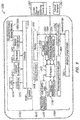
- Fig. 9 is a block diagram of an apparatus 1000, in accordance with the present invention.
- the apparatus 1000 is used to implement the apparatus 900 of Figs. 2A-2E .
- the apparatus 1000 may include an interface board 1010, a power region 1030, and a control board 1050. As described, each of the interface board 1010, power region 1030, and control board 1050 may be located in a lower portion of the apparatus 1000.
- the interface board 1010 may include a controller 1012 that may receive user data from one or more sensors of the interface board 1010.
- the controller 1012 may be coupled to a compass/accelerometer 1018, a gyroscope 1020, an ambient light sensor 1022, a touch sensor 1024, and infrared sensors 1026, and receive data therefrom.
- Each of the sensors 1018, 1020, 1022, 1024 and 1026 may provide respective data to the controller 1012.
- the controller 1012 may in turn provide the data to a processor 1052 included in the control board 1050.
- the processor 1052 may be used to implement the processor 12 of Fig. 1 .
- the processor 1052 may use the data to identify information associated with the user 1, as described herein.
- the controller 1012 may filter and/or otherwise modify data received from the sensors prior to providing the data to the processor 1052.
- the touch sensor 1024 may be used to determine whether the user I is in physical contact with the apparatus 1000.
- the compass/accelerometer 1018 and the gyroscope 1020 may be additionally or alternatively be used to determine whether the user 1is in contact with the apparatus 1000.
- the gyroscope 1020 may provide signals indicating that the apparatus 1000 has been tilted as a result of the user 1touching the apparatus 1000. In this manner, the apparatus 1000 may determine whether the user 1is in physical contact with the apparatus 1000 even if the touch sensor 1024 docs not detect any physical contact with the user 1at a portion of the apparatus 1000 where the touch pad of the touch sensor 1024 is disposed.
- a speed, a frequency or an amplitude of displacement which the apparatus 100 sways back and forth may be used to determine the manner in which the user 1 is in physical contact with the apparatus 1000.
- a lower speed, frequency or larger amplitude of displacement may, for instance, indicate a more forceful touch.
- the interface board 1010 may further include an LED driver 1016 and LEDs 1014 that may provide visual responses to a user 1.
- the controller 1012 may cause the LED driver 1016 to illuminate one or more of the LEDs 1014 to provide a specified light pattern of a particular visual response.
- the interface board 1010 may further include a speaker 1028 that may provide auditory responses to the user 1. Auditory responses may be based on one or more audio signals received from the audio control logic 1070, described in further detail below.
- the power region 1030 may be located between the interface board 1010 and the control board 1050 and include a board connector 1032 and a battery 1034.
- the board connector 1032 may provide data between respective components of the interface board 1010 and the control board 1050.
- the board connector 1032 may provide signals from the audio control logic 1070 to the speaker 1028.
- specific connections provided by the board connector 1032 are not shown in Fig. 10.
- the power region 1030 may further include a battery 1034 that may be applied to implement the battery 930 of Figs. 2A-2E .
- the battery 1034 may store and/or provide power to one or more components of the apparatus 1000.
- the control board 1050 may include the processor 1052.
- the processor 1052 governs operation of the apparatus 1000 and may execute one or more computer readable instructions stored in the non-volatile memory 1056 such that the apparatus 1000 may operate as described herein.
- the processor 1052 may receive data from one or more of the devices of the control board 1050.
- the processor 1052 may receive data from the camera 1058, network device 1066, wireless network device 1068, and/or audio control logic 1070.
- the camera 1058 may provide visual data associated with the user 1, such as a facial expression or natural gesture of the user 1.
- the network device 1066 may communicate with one or more wired networks, such as a USB network or Ethernet network, and the wireless network device 1068 may communicate with one or more wireless networks.
- the network device 1066 and/or the wireless network device 1068 may allow the processor 1052 to communicate with one or more external apparatuses 1080 (e.g., content devices, such as a television, a streaming device, etc.) and an external computer 1081 using a wired or wireless network.
- the audio control logic 1070 may be coupled to one or more microphones 1072 and may receive audio data (e.g., voice data) associated with the user 1.
- the audio control logic 1070 may provide audio data to and receive audio data from the processor 1052. Audio data may be provided from the microphones 1072 to the processor 1052, and may be provided from the processor 1052 to the speaker 1028.
- the audio control logic 1070 may include one or more analog-to-digital converters and digital-to-analog converters and/or may further include one or more audio filters or codecs.
- the control board 1050 may further include a vibrator 1078 that may provide vibration responses to the user 1.
- the processor 1052 may cause the vibrator 1078 to vibrate in a particular manner during a vibrational response.
- the control board 1050 may include power circuitry comprising an inductive charge module 1060, charging control logic 1062, and power management control logic 1064.
- the inductive charge module 1060 may be coupled to an external charging device, such as a charging mat or port (not shown) and provide the charge received from the charging mat to the charging control logic 1062.
- the charging control logic 1062 may charge the battery 1034.
- the power management control logic 1064 may manage allocation of power to components of the apparatus 1000.
- the apparatus 1000 may include a coil (not shown) for inductive charging.
- the coil may be stacked with (e.g., over or under) a touch pad, such as the touch pad 908 of Fig. 2E .
- the apparatus 1000 may selectively enable one or more components according to a mode of the apparatus 1000. In this manner, the apparatus 1000 may increase power usage efficiency.
- the apparatus 1000 may determine that a user 1 is not in proximity and enter a standby mode.
- the processor 1052 may enter low power operation (e.g., in a standby state).
- the power management control logic 1064 may cause the processor 1052 to enter low power operation, for instance, responsive to the user 1 not being in proximity to the apparatus 1000 for a particular amount of time.
- the controller 1012 and one or more proximity sensors of the apparatus 1000 may continue to operate. Responsive to the one or more proximity sensors detecting that a user 1 is in proximity to the apparatus 1000, the processor 1052 may exit the low power operation and begin processing user data.
- other features and/or components of the apparatus 1000 may be selectively enabled as well. Speech analysis, for example, may be selectively enabled (e.g., by the processor 1052) based on whether the apparatus 1000 is in contact with the user 1 in a second stillness mode 120 in Fig. 2 . In another example, the camera 1058 may be selectively enabled based on whether the apparatus 1000 is in contact with the user 1 in a second stillness mode 120 in Fig. 2 . In some examples, the apparatus 1000 may select a mode based on whether the apparatus 1000 is charging. In response, the apparatus 1000 may selectively enable one or more features and/or components of the apparatus 1000. For example, the apparatus 1000 may remain connected to one or more available wireless networks while charging. Additionally or alternatively, the apparatus 1000 may transfer and/or backup data to an external computer 1081, when charging.
- Speech analysis for example, may be selectively enabled (e.g., by the processor 1052) based on whether the apparatus 1000 is in contact with the user 1 in a second stillness mode 120 in Fig. 2 .
- the interface board 1010 and control board 1050 may each be an integrated circuit, and accordingly, respective components of the interface board 1010 and control board 1050 may be integrated. In other examples, one or more respective components may be separately installed and not integrated in either of the interface board 1010 and the control board 1050.
- the interface board 1010, the power region 1030, or the control board 1050 it will be appreciated that in other embodiments components of the apparatus 1000 may be arranged in other configurations.
- the compass/accelerometer 1018 and/or the gyroscope 1020 may be included in the control board 1050 and/or the microphones 1072 and the audio control logic 1070 may be located in the interface board 410.
Description
- This application claims the benefit under 35 U.S.C. § 119 of the earlier filing date of
U.S. Provisional Application Serial No. 62/266,423, filed December 11, 2015 - This invention relates to an apparatus and a method for detection of states of an apparatus, including apparatuses and methods for interfacing with a user based on the detection of a state, such as a stationary state, of the apparatus and providing a response based on the state of the apparatus.
- Conventional man machine interfaces (e.g., computer user interfaces) operate by the detection of specific commands from the user. The detection is typically performed by the user submitting specific inputs via input devices configured to receive the specific user input. More recently, user interfaces have been developed in which the detection of specific gestures or voice commands of a user are correlated by the user interface into specific commands that the interface is programmed to receive. Typically an input by a user requires some action (e.g., inputting a command, a particular gesture or a particular voice command) for the machine to receive a command. For example, in some of the conventional methods, the user directly provides one or more entries through input devices (e.g., keys, buttons, a mouse, a touch screen, a microphone, etc.) to signal one command or a sequence of commands to explicitly control the machine (e.g., an electronic apparatus). In other examples, the commands are received in the form of a particular gesture or user motion. These types of conventional interfaces require the user's attention and consciousness to the input of the commands. As such, conventional interfaces typically require the user's specific attention to the task to explicitly control the machine, which may be disruptive, cumbersome, or annoying for the user. Thus, user interfaces which enable interaction with an electronic apparatus in a more natural and implicit manner may be desirable.
US2015/026647 A1 discloses a mobile terminal and a control method thereof. The mobile terminal includes a main body that is configured to be wearable on a specific portion of a user's body, a sensing unit that is configured to sense whether or not the main body has been worn, and also sense a user gesture for deciding the worn position of the main body, and a controller that is configured to decide the worn position of the main body according to the sensed user gesture, and setting a user input for generating a first control command in a different manner based on the decided worn position.US2014/379341 A1 discloses a portable terminal, and more particularly, to a portable terminal and a method of detecting a gesture and controlling a function. A method of controlling a function of a portable terminal includes: detecting a gesture; activating a voice recognition module in response to the detected gesture; and analyzing a voice input into the activated voice recognition module, and executing a function corresponding to the input voice.US2014/139466 A1 discloses devices, systems, and methods for empathetic computing. - The present invention relates to a method according to
claim 1, and to an apparatus according toclaim 10. -
-
Fig. 1 is a simplified block diagram of an apparatus in accordance with the present invention. -
Fig. 2A is a perspective view of an apparatus in accordance with the present invention. -
Fig. 2B-2E are perspective views of portions of the apparatus inFIG. 2A . -
Fig. 3 is a flow diagram of a method of interfacing with a user including detecting a stationary state of an apparatus, in accordance with the present invention. -
Fig. 4A is a flow diagram of processing of information associated with a user by the apparatus, in accordance with an embodiment not covered by the claims. -
Fig. 4B is a table diagram of stillness level detection based on the detection of the motion of the apparatus, in accordance with an embodiment of the present disclosure -
Fig. 4C is a flow diagram of detection of a motion of the apparatus by a gyroscope, in accordance with an embodiment not covered by the claims. -
Fig. 5 is a flow diagram of detection of a command for an external apparatus based on gesture of a user, in accordance with an embodiment not covered by the claims. -
Fig. 6 is a flow diagram of detection and extraction of an utterance of a user, in accordance with an embodiment of the present disclosure, -
Fig. 7 is a flow diagram of a method of interfacing with a user including processing information associated with the user in a stationary state of an apparatus, in accordance with an embodiment not covered by the claims. -
Fig. 8 is a flow diagram of a method of interfacing with a user including processing information associated with the user in a stationary state of an apparatus, in accordance with an embodiment not covered by the claims. -
Fig. 9 is a block diagram of an apparatus, in accordance with an embodiment of the present disclosure. -
Fig. 1 is a simplified block diagram of anapparatus 10 in accordance with the present invention. For example, theapparatus 10 includes a processor 12, a proximity sensor 11 and amotion sensor 13. While the application refers to "a'" processor, "a" proximity sensor, and "a" motion sensor, it will be understood that any of these components (e.g., the processor, proximity sensor and/or the motion sensor) can include one or more individual processors, which may operate in parallel, and/or one or more sensors of the same or different type, the sensor data from which may be used to provide the data needed for performing the functions of the apparatus described herein. The proximity sensor 11 detects auser 1 in proximity of theelectronic apparatus 10. For example, the proximity sensor 11 may include a touch sensor, such as capacitive sensor, a pressure sensor, or a combination thereof, which may detect physical contact (e.g., by the user 1) with the electronic apparatus 10 (e.g., touching theelectronic apparatus 10, holding theelectronic apparatus 10, etc.), In some examples, the proximity sensor 11 may include a passive infrared sensor, a capacitive sensor, a gyroscope, an accelerometer, a camera, a microwave sensor, an ultrasonic sensor, a laser based sensor, a photoelectric sensor, a plurality of microphones, a pressure sensor, a magnetic sensor, a thermal sensor, a radar, a combination thereof, which may be used to estimate that theuser 1 is in proximity of theapparatus 10 by estimating a distance between theuser 1 and theapparatus 10 or by detecting theuser 1 in a sensor range from theapparatus 10. For example, theapparatus 10 is able to detect the user in proximity by deleting a movement of theapparatus 10, for example when the apparatus is picked up by theuser 1, using a combination of the gyroscope and the accelerometer which in this instance may function as the proximity sensor 11. In some examples, wireless communication devices, such as WiFi, Bluetooth, LTE, near-field communication (NFC), or radiofrequency identification (RFID) enabled devices, may function as the proximity sensor 11, which may detect a portable device (e.g., tablet, smartphone, smart watch, etc. (not shown)) of theuser 1 in proximity by pairing or handshaking with the portable apparatus that may be held or worn by theuser 1, The proximity sensor 11 may be coupled to the processor 12. In some examples, the proximity sensor may be coupled to a controller which controls operation of the proximity sensor and/or other sensors of the apparatus (e.g., activating/deactivating sensors, directing sensor data to the processor and/or to storage) and the proximity sensor 11 may thus be operatively coupled to the processor 12 via the controller. The proximity sensor 11 may provide sensor data to the processor 12, for example upon detection of theuser 1 in proximity of theapparatus 10, as theuser 1 approaches theapparatus 10. The processor 12 may cause theapparatus 10 to enter a first mode responsive to detection of theuser 1 in proximity. The first mode may be interchangeably referred to herein as stillness detection mode. - As illustrated, the
apparatus 10 includes amotion sensor 13 and one or more additional sensors 14 and output devices 18. Upon entering the first mode, themotion sensor 13, which is activated responsive to entering the first mode or prior to entering the first mode, begins to monitor movement of the apparatus, The stillness detection mode includes two phases. During a first phase, theapparatus 10 is configured to process sensor data from the motion sensor to detect initialization movement of theapparatus 10. The initialization movement may be indicative of the user picking up the apparatus 10 (e.g.. lifting theapparatus 10 from a surface, such as a table or desk, supporting the apparatus prior to the user coming in proximity). - In some examples, the initialization movement may be detected responsive to detection of an acceleration and/or displacement of the apparatus along a direction normal to the supporting surface, which may be indicative of the apparatus having been picked up by the user. In some embodiments not covered by the claims, the initialization movement may be detected responsive to the detection of a touch by the user with a capacitive touch sensor positioned on a supporting side (e.g., the bottom side) of the apparatus, which may be indicative of the apparatus having been picked up and being held in the palm of the user.
- The initialization movement invokes the second phase of the stillness detection mode. During the second phase (i.e., following detection of the initialization movement), the apparatus is configured to monitor motion of the apparatus in order to detect a stillness or stationary state of the apparatus, In this phase of the stillness detection mode, the processor periodically receives sensor data (e.g., at frame rates of 100ms or 200ms) and analyzes the data to identify if the
apparatus 10 has achieved a stationary state. For example a stationary state, which may be interchangeably referred to as moment of stillness, may be a detected based on the processor determining, from the motion data. that theapparatus 10 has experience no movement for a predetermined period of time, such as 1 second or multiple consecutive seconds. Some users may naturally have a more steady hand than others and thus this predetermined period of time may be configurable to reflect different user's natural tendencies. For example, for a user with a relatively steadier hand, the predetermined period which triggers a response may be extended for example to 2 or more seconds so as to filter out the natural steadiness of this particular user's hold. For users with a relatively less steady hand, the predetermined period which triggers, a response may be reduced to for example to 1.5 seconds or less. The configuration of the predetermined period of stillness may be performed by the user (e.g., during set up of the apparatus) or may be performed by the apparatus (e.g., via machine learning over a training period). - Continuing with the description of the
apparatus 10 inFIG. 1 , themotion sensor 13 may be coupled to the processor 12 and/or intermediate controller (not shown) operatively connecting themotion sensor 13 to the processor 12. In some examples, the processor 12 activates themotion sensor 13, responsive to entering the first mode. In other examples, themotion sensor 13 may be active prior to detection of the user in proximity (e.g.. prior to entering the first or stillness detection mode), e.g., responsive to powering up theapparatus 10. Themotion sensor 13 provides motion data responsive to movement of theapparatus 1 while theapparatus 10 is in the first mode. For example, themotion sensor 13 may be either a gyroscope, an accelerometer, a camera, a passive infrared detector, a microwave sensor, an ultrasonic sensor, a capacitive sensor, a microphone, a photoelectric sensor, a thermal sensor, a pressure sensor, a magnetic sensor, a heart rate sensor, or a combination thereof. The processor 12 detects a stationary state of theapparatus 10 based on the motion data. For example, the processor 12 detects the stationary state, if the processor 12 detects back of a motion of theapparatus 10 for a predetermined period of time following the detection of the initialization movement. For example, themotion sensor 13 may include a gyroscope that detects and provides orientation information of theapparatus 10, and the processor 12 may detect the stationary state of theapparatus 10 if the orientation information indicates no change in the orientation of theapparatus 10, In some examples, themotion sensor 13 may alternatively or additionally include an accelerometer, which is operable to detect and provide acceleration information. The processor 12 may detect a stationary state of theapparatus 10 in the absence of acceleration of the apparatus as indicated by the acceleration information provided by the accelerometer. Depending on the sensitivity of themotion sensor 13, minute changes in orientation, acceleration or other detected motion which are below a motion threshold (e.g., less than 0.5 degrees of rotational change, or less than 1mm of translational change) may be ignored for purposes of detecting a stationary state. Other thresholds may be used, for example as may depend upon the natural movement tendencies (e.g.. steady vs. shaky hands) of the user. - The processor 12 causes the
apparatus 10 to enter a second mode responsive to the detection of the stationary state of theapparatus 10. Upon entry of the second mode (e.g., upon detection of a stationary state following the initialization movement), theapparatus 10 provides a response. In some examples, the response is feedback to the user. The response is additionally or alternatively a communication (e.g., a wireless transmission of a command or data) from/to theapparatus 10 to/from an external apparatus 16. In some examples, in the second mode, the processor 12 may activate additional sensors 14 and/or output devices 18. The additional sensors 14, if applicable, may be used alone or in combination with themotion sensor 13. to monitor theuser 1. such as to obtain information associated with theuser 1. Information associated with theuser 1 may include any voice, image and motion data recorded while theuser 1 is holding theapparatus 10. The output devices, which may include one or more feedback devices and/or one or more wired or wireless communication devices, may be configured to provide response. As described herein, the response is feedback and/or communication with external electronic devices (e.g., external apparatus 16, which may be a computer, a smartphone, a television, a radio or other media device, or a household appliance such as a thermostat, a refrigerator, a cooking appliance, or other). In some examples, the communication with the external apparatus may include a command to the external apparatus 16 to transmit data to theapparatus 10 and theapparatus 10 may provide feedback based on the data received from the external apparatus 16, - A feedback response may include a visual, audible, or tactile response, which may be generated responsive to the detection of the stationary state alone or in conjunction with a communication response. The feedback response may be generally directed toward the user, such as to notify the user of the acknowledged interaction. A visual feedback response may be provided by way of illuminating a light or producing a pattern of light with one or a plurality of light sources of the apparatus. Similarly, an audible response may be provided by way of generating a sound or producing a pattern of sounds with one or a plurality of sound sources of the apparatus. Tactile responses may be provided by way of internally generated movement (e.g., via an actuator such as a vibrator) by the apparatus, which may cause the apparatus to move in a given manner (e.g., vibrate, hop. tilt or rock from side to side, move such as to cause the apparatus to change facing orientation with respect to the user, or motion which may resemble nodding such as tilting the apparatus toward and away from a direction facing the user). Providing feedback responses may be useful, not only during normal course of use of the
apparatus 10 so as to provide a sense of communication between the user and the apparatus which may be pleasing to the user, bur especially during a training period so as to aid the user in naturally learning the user interface provided by theapparatus 10. - Communication responses may be provided by the
apparatus 10, for example in the form of a wireless transmission to an external apparatus 16. A communication response may be configured to elicit a response from the external apparatus 16. For example, the communication (e.g., wireless transmission) may include a command for controlling a function of the external apparatus 16. The external apparatus 16 may perform a function (e.g., turn On or Off, control volume, temperature, or other parameter, begin playback of audio or visual information, store information, retrieve information, etc.) responsive to the communication from theapparatus 10, Different communications may be generated by theapparatus 10 depending on the user's actions in relation to theapparatus 10 during the stillness detection mode, as further described herein. In some examples, theapparatus 10 may be configured to receive information associated with the user during the stillness detection mode and the communication may include or be based, at least in part, on the received information, as farther described. - Referring back to the example in
FIG. 1 , theapparatus 10 may receive information associated with theuser 1 from the sensors 14, which information may be processed by the processor 12 for providing a response with theapparatus 10, e.g., with one or more of the output devices 18. As discussed, in some examples, the response provided by theapparatus 10 may be directed to an external apparatus 16 rather than the user, such as by transmitting a cammand, data, instructions, or other type of communication. The communication response may be provided by communication circuitry of theapparatus 10, e.g., bycommunication device 15. - As described, the
apparatus 10 may include one or more additional sensors 14. For example, one additional sensor 14 may be a camera. The camera may capture a sequence of images of theuser 1. Another additional sensor may be a microphone, which may capture sounds from the user. In some examples, the additional sensors may include additional motion sensor(s). In some examples, sensor data obtained by the additional sensors may be supplemeated by sensor data from themotion sensor 13, in order to capture a sequence of motion data of theuser 1 during the stillness detection mode. The processor may process sensor data obtained during the stillness detection mode. e.g., for providing feedback and/or response(s) as described herein. - The
apparatus 10 may further include amemory device 17 configured to store data during the operation of theapparatus 10. For example, thememory device 17 may store the sequence of motion data, images, sounds, or other information associated with theuser 1 received by theapparatus 10 In some embodiment, the processor 12 may retrieve previously stored sequences from thememory device 17 for analysis, for example to interpret a gesture of theuser 1. The term gesture may be used to refer to any type of natural action of the user, such as actions performed by the user's hand holding the apparatus or action performed by other parts of the user such as the user's face (e.g., facial expressions including winking, smiling, frowning, etc.). The processor 12 may be configured to extract information associated with theuser 1 from the gesture of theuser 1. - In some examples, the additional sensors 14 may include a microphone. The microphone may be operatively associated with the processor 12 and
memory 17 to detect and record sound by or around theuser 1. In some examples, theapparatus 10 may be configured to detect utterances of a specific user. For example, the microphone may detect ambient sounds by or around theuser 1 and identify the sound associated with theuser 1, including the user's voice, or other sound generated by the user (e.g., cough, sneeze, surrounding noise) from the ambient sounds. Theapparatus 10 may be configured, e.g., during a set-up or training process, to recognize the sound associated with theuser 1. The processor 12 may extract information associated with theuser 1 from the sound associated with theuser 1. In some examples, theapparatus 10 may recognize speech and may extract utterances irrespective of the user producing the utterances. - As described, the processor 12 provides a response in the second mode and in some cases, the response may be provided automatically by the
apparatus 10 responsive to entering the second mode. The term automatically, as used herein, is generally meant to imply that an action or response performed by theapparatus 10 occurs automatically responsive to a trigger without requiring further action or input by the user. The response includes a response to the user. The response involves a communication with an external apparatus. For example, with respect to the former, theapparatus 10 may include an output device 18, such as one or more light emitting diodes (LEDs), a speaker, one or more vibrators, etc. The response may be a visual response (e.g., illuminating a light or a pattern of lights with one or more light emitting diodes (LEDs)), an auditory response (e.g., generating a sound or a pattern of sounds with the one or more speakers), or a tactile response (e.g., causing the apparatus to vibrate, rock, or generating another type of motion with the one or more vibrators). - The
apparatus 10 may include a wired or awireless communication device 15 that transmits a command or data to an external apparatus 16 (e.g., another computing device, a electronic appliance such as a TV, radio, another media device or a household appliance). In some examples, the command may include a command to perform a function of the external apparatus 16 (e.g., turn the appliance on or off, volume control, begin playback of audio or video, temperature control of thermostat or a cooking appliance, etc.). The command or data transmitted to the external apparatus 16 may be based on the mode ofapparatus 10. In some examples, the command or data may be transmitted responsive to theapparatus 10 entering a particular mode, such as responsive to entering the second mode. For example, theapparatus 10 may be configured to transmit a command to a media device to turn the media device ON responsive to the apparatus entering the second mode. In some examples, the command or data transmitted to theexternal apparatus 10 may be based on the information associated with theuser 1. In some examples, the data may include information (e.g., a tag or other metadata) to be associated with data in the external apparatus 16. In some examples, the data transmitted to the external apparatus 16 may be a recording associated with the user (e.g., audio, a still image or video, and/or context associated with the recording), which may be transmitted to the external apparatus 16 for storage and/or further processing by the external apparatus 16. In some examples, theapparatus 10 may transmit both data and a command (e.g., a recording and a command to playback the recording) upon entering a given mode. In some examples, theapparatus 10 may continue to monitor the state of the apparatus (e.g., via motion data) following the providing of the response in order to extract additional information and/or provide additional responses, for example during a second stillness detection mode. - In some examples, responsive to the command and/or data from the
apparatus 10, the external apparatus 16 may perform the command (e.g., retrieve user data from storage) and/or may provide a return communication to theapparatus 10 based on the user data. Theapparatus 10 may receive the return communication from the external apparatus 16. Responsive to the return communication, and in some cases jointly with the information associated with the user and/or a current state of theapparatus 10, theapparatus 10 may provide feedback to theuser 1. The process of interfacing with theuser 1 may continue until theapparatus 10 is replaced onto its supporting surface (e.g., table or desk), which may be detected for example by no longer detecting contact with a bottom sensor of theapparatus 10, which may return the apparatus to the first phase of the stillness detection mode or the standby mode, of the apparatus no longer detects the user in proximity. -
Fig. 2A is a perspective view of anapparatus 900 in accordance with the present invention. Anapparatus 900 may be used to implement theapparatus 10 ofFig. 1 . Theapparatus 900 may include elements that have been previously described with respect to theapparatus 10 ofFig. 1 . For example, theapparatus 900 is a handheld apparatus having a relatively spherical shape. Theapparatus 900 may be sized to fit in the palm of theuser 1, which may enables theuser 1 to perform various gestures effortlessly while holding the apparatus. By detecting and responding to moments of stillness of the user while holding theapparatus 900, and thus moments of stillness of the apparatus itself, theapparatus 900 may be configured to provide an effortless and unconscious interface between the user and any electronic device within the users living or working space. For example, theapparatus 900 may be aesthetically, economically, or otherwise pleasingly shaped, which may not only enhance the user's living or working environment but may encourage the user to pick up and/or hold theapparatus 900. Holding theapparatus 900. aside from any computer/user interface enabled thereby, may be pleasing and/or calming to the user, The natural interaction of the user with theapparatus 900 may thus enable a more intuitive and user friendly interface, e.g., without requiring significant or any effort, attention, or intention from the user to solicit responses from theapparatus 900 itself and/or other apparatuses in the user's environment. In some examples, the shape and/or the external appearance of the apparatus may provide an ornamental/aesthetic function. - The
apparatus 900 may include anupper portion 901 and alower portion 902 that may form an enclosure of theapparatus 900. In some examples, the enclosure may be made from a plastic material (e.g., plastic materials suitable for injection molding as is typically known in the consumer electronic industry). In some examples, a portion of the housing. such as the upper portion, may be translucent. In some examples, the enclosure or a portion thereof, may be made from acrylic. In further examples, the enclosure, or a portion thereof, may be formed of a natural material, such as wood, bamboo, quartz, marble, fabric made from synthetic or natural fibers, leather, or a combination thereof, which may provide distinctive color, texture, and tactile sensation and natural comfort that may reduce user's consciousness and stress when interfacing with theapparatus 900. For example, theupper portion 901 and thelower portion 902 may be either substantially hemispherical or hemi-ellipsoidal in shape. Theapparatus 900 may maintain a static position when rested on a relatively flat surface that enables the apparatus to be in a stationary state with case. Theapparatus 900 may include acamera 903. As previously described thecamera 903 may be used for proximity sensing, motion sensing, and gesture detection. Thecamera 903 may be able to detect free expressions of theuser 1 from facial gesture, hand movement or body movement Thecamera 903 may provide images to the processor 12. -
Fig. 2B is a perspective view of theapparatus 900 in accordance with an embodiment not covered by the claims. Relative toFig. 2A , theupper portion 901 of theapparatus 900 is not shown. As illustrated, theapparatus 900 may include alight adjusting device 910. Thelight adjusting device 910 may adjust light provided by one or more components located within thelower portion 902, thus the light provided by theapparatus 900 may be split, scattered and/or "softened," thereby reducing recognition of individual light sources of theapparatus 900, -
Fig. 2C is a perspective view of an apparatus in accordance with an embodiment not covered by the claims. Relative toFig. 2B , thelight adjusting device 910 of theapparatus 900 is not shown, As illustrated, theapparatus 900 may include a plurality ofproximity sensors 906, which may be used to implement the proximity sensor 11 ofFig. 1 . Each of theproximity sensors 906 may determine the proximity of theuser 1 to theapparatus 900 and may be any infrared sensor known in the art. (e.g, cameras, a microwave sensor, an ultrasonic sensor, a laser based sensor, a magnetic sensor. an optical sensor, passive infrared sensors. a thermal sensor, a radar. microphones). As illustrated, in some examples,proximity sensors 906 may be disposed around a circumference of theapparatus 900. In other examples, theproximity sensors 906 may be located in other locations of theapparatus 900, Theapparatus 900 may include aninterface board 915. Theinterface board 915 may include a plurality of light emitting devices, such as light emitting diodes (LEDs) 920. Each of theLEDs 920 may provide light through thelight adjusting device 910 and theupper portion 901 to provide light patterns of visual responses to theuser 1. While shown as being arranged in a particular pattern (e.g., a spiral), theLEDs 920 may be arranged within theinterface board 915 in any desired pattern, such as a grid. Theinterface board 915 will be explained in further detail herein (see Fig. 10). -
Fig. 2D is a perspective view of an apparatus in accordance with an embodiment not covered by the claims. Relative toFig. 2C , theinterface board 915 is not shown. As illustrated, theapparatus 900 may include abattery 930 and atouch sensor 932. Thebattery 930 may be any battery, including for example, rechargeable batteries, known in the art and may store and provide power to various components of theapparatus 900. The battery may be detachable charged outside theapparatus 900 or installed integrated with an internal charger for wired/wirelessly charging within theapparatus 900. Thetouch sensor 932 may include a touch sensor belt disposed circumferentially about theapparatus 900 and may detect a contact of the user when the user I touches any portion of a surface of theapparatus 900 where thetouch sensor 932 is disposed. Thetouch sensor 932 may be capacitive, resistive, piezoelectric, or a combination thereof. -
Fig. 2E is an exploded perspective view of an apparatus in accordance with an embodiment not covered by the claims. Relative toFig. 2D . thebattery 930 is not shown. As illustrated, thetouch sensor 932 may include a touch pad 908. The touch pad 908 may include a plurality of radial electrode lines radially extending from the center of the touch pad 908 and may determine whether theapparatus 900 is supported by a surface, such as a table or a palm of the user I. In some examples, theproximity sensors 906 may be periodically disposed along the touch sensor belt of thetouch sensor 932. - The apparatus (e.g., apparatus 10) interfaces with the
user 1 and/or with external apparatuses (e.g., other computing or electronic devices in the user's environment), by detecting a stationary state and in some examples, by also detecting information associated with theuser 1.Fig. 3 is a flow diagram of a method of interfacing with a user including detecting a stationary state of an apparatus (e.g., apparatus 10), in accordance with the present invention. - Initially, the
apparatus 10 may he powered on (e.g., via a battery) and is in a standby mode (S200). While theapparatus 10 is in a standby mode 100, the proximity sensor 11 is active so as to detect the user I when the user comes in proximity (S201) to theapparatus 10. The proximity sensor 11 continues to sense for an object (e.g., the user) in proximity until the so detected. Depending on the proximity sensor(s) employed, the user's approach or proximity to theapparatus 10 may be detected based on, for example, visual information such as images including one or more objects within the field of view of the sensor (e.g., an image capture device), auditory information such as change of an environmental noise level, optical, thermal or electromagnetic information caused by the presence of the user I within a predetermined range of theapparatus 10, or tactile information caused by the user's contact (e.g., touch) by theapparatus 10, In some examples, the user may be detected to be in proximity responsive to a detected touch on a touch sensor of theapparatus 10. In some examples, the user may be detected to be in proximity without requiring physical touch between the user and apparatus, such as responsive to detecting with for example an optical, thermal, or electromagnetic sensor, the user within a sensing range of the sensor. Theapparatus 10 enters astillness detection mode 110 responsive to detection of the user I in proximity (S201). During the stillness detection mode, the apparatus is configured to monitor movement of the apparatus for first detecting an initialization motion and then detecting a stillness or stationary state whereby a response may be provided responsive to the detection of the stationary state. As described, the apparatus, during a first phase of the stillness detection mode, may monitor movement of the apparatus to detect the initialization movement which may indicate that theapparatus 10 has been picked up and/or placed on the user's palm. Upon detecting of the initialization movement, theapparatus 10 may continue to monitor its movement during thestillness detection mode 110 for detecting a stationary state. - In the stillness detection mode, the processor 12 activates the
motion sensor 13 if not already active, and themotion sensor 13 may periodically (e.g.. every 1 second, 1 millisecond, etc), provide motion data to the processor (S202). The processor may process the motion data frames to identify a stationary state of theapparatus 10. For example, the motion data may be visual information, auditory information, velocity/acceleration information, orientation information, positional information, etc., that may change due to displacement (e.g., changes in a location) or tilts (e.g., changes in an orientation) of theapparatus 10. The processor 12 may periodically receive the motion data from themotion sensor 13, (S203) The processor 12 detects a stationary state I of theapparatus 10 based on the motion data (S204) during the stillness detection mode. For example, the processor 12 analyzes the motion frames during the stillness detection mode and detect the stationary state of theapparatus 10 by detecting lack of a motion of the apparatus for a predetermined period. The predetermined period may be a fixed period of time, flexibly programmable for each user, or depending on contexts of theuser 1. - The
apparatus 10 enters a secondstillness detection mode 120, responsive to detection of the stationary state of theapparatus 10. In the secondstillness detection mode 120, theapparatus 10 may be configured to generate farther responses, In some examples, the apparatus may record information associated with the user (e.g., audio, still image(s) or video data, motion data while theapparatus 10 is being held by the user, etc.) which may be used when providing a response during the secondstillness detection mode 120. For example, the processor 12 may process information associated with the user I (S205) received from the sensors 14 in the second stillness detection mode to determine and provide further response(s) (e.g., S206, S207). Depending on the information recorded, theapparatus 10 provides a feedback response via a feedback output devices 18 (S206) or via acommunication output device 15. Theapparatus 10 may continue to monitor interaction between the user andapparatus 10 and generate visual, auditory, or tactile responses to theuser 1 communication response to external appliance(s), which responses may include any one or more of the responses described with reference to the firststillness detection mode 110. - A response by the
apparatus 10 during the second stillness detection mode is based at least in part, on a detected pattern, for example a pattern of stationary states of the apparatus 10 (or moments of stillness) during the second stillness detection mode. In some examples, the response may be based, at least in part, on a detected motion or pattern of movements of the apparatus, In some examples, the response may be based, at least in part, on recorded information associated with the user (e.g., audiovisual recording of the user). -
Fig. 4A is a flow diagram of a process in accordance with the present disclosure. Theprocess 400 inFig, 4A is used to process information associated with a user for example to detect one or more stationary states of theapparatus 10. The process may begin with theapparatus 10 receiving information associated with a user (as shown in block S410). - Upon receiving information associated with a user, in this case motion data, the
apparatus 10 processes the information of the user I (as shown in block 5412) to detect one or more stationary states (as shown in block S414). The processor 12 detects one or more periods of the stationary state of theapparatus 10 based on the motion data. In some examples the apparatus may identify a level of stillness (e.g., as described further with reference toFig. 4B ) and/or a pattern of the stationary states, as shown in block S418. In some examples, different degrees of stillness may correspond to different stationary states and the processor may categorize the detected one or more stationary states in accordance with the degree of stillness (e.g., a calm state, a still state, etc.), as shown in optional block S416. In some examples, the determination of stationary state may be binary, e.g., the apparatus is either in a stationary state if a condition is met (e.g., lack of motion as defined by a motion thresholds to filter out noise) or the apparatus is in a non-stationary state if the condition is not satisfied. The process may be configured to end upon detection of a large number of non-stationary states in a sequence, and in some examples, responsive to detection of a greater number of consecutive non-stationary states than a predetermined threshold (e.g., 2, 3, 4 or more consecutive non-stationary states), as shown in block S422. which may cause the apparatus to exit the second stillness detection and return to the first stillness detection mode, and in some examples to phase two of the first stillness detection mode whereby theapparatus 10 may monitor motion data to identify a subsequent stationary state (e.g., to enter the second stillness detection mode) or a particular motion state (e.g., for performing further functions as described herein). - The processor 12 may record a sequence of states of the
apparatus 10 including one or more stationary states or non-starionary states occurring in the second stillness detection mode to detect a pattern of the stationary state in the second stillness detection mode. Theapparatus 10 is configured to provide a response upon detection of one or more stationary states, and in some cases a particular response is provided responsive to detection of a particular level of stillness or pattern of stationary states, as shown in block S420. Based on the detected level of stillness or pattern of the stationary states, theapparatus 10 may be configured to extract further information associated with the user 1 (e.g., begin recording audio and or images/video), transmit a command to control the external apparatus, and/or provide feedback (e.g., blinking, playing sound, or vibration) to theuser 1 In some examples, theapparatus 10 may store a plurality of sequences of states (e.g., in the memory device 17) and determine a pattern of the stationary states by comparing a currently recorded sequence of states of theapparatus 10 with the plurality of stored sequences. In some examples, the stored sequences may be preprogrammed in theapparatus 10, e.g., stored in in a pre-existing database of sequences generated by the user, and the pattern may be determined based on the sequences in the database of sequences generated by the user, For example, theapparatus 10 may use a pre-existing database of sequences obtained from different users, and the pattern may be determined based on sequences in the pre-existing database of sequences. In some examples, the stored sequences may be stored in a database of sequences obtained only fromuser 1 and/or theapparatus 10 may be configured to add sequences to the database for enhancing and tailoring the pattern recognition to a particular user, - In some examples, the pattern detection may include detecting a level of stillness (e.g., as shown in block S418 of
Fig. 4A ).Fig. 4B is a table diagram of stillness level detection based on the detection of the motion of the apparatus in accordance with an embodiment of the present disclosure. For example, theapparatus 10 may record a sequence of the states of theapparatus 10. In the illustrated example, ten cycles are shown but a different number of cycles may be analyzed for determining a pattern in accordance with other examples. The states may include a "rough" state where theapparatus 10 is in a dynamic state, a first stationary state (e.g., a "calm" state) or a second stationary state (e.g., a "still" state) which corresponds to a greater degree of stillness than the first stationary state. The illustrated Sequences I and II start with theapparatus 10 in the "rough" state. In Sequence I, a "still" state of the apparatus is recorded at the third, fourth, seventh, ninth and tenth cycles, and a "calm" state of the apparatus is recorded at the second, fifth, sixth and eighth cycles. In Sequence II. a "calm" state is recorded from the second cycle to the tenth cycle. Because of Sequence I has a greater number of occurrences of the "still" state than Sequence If, theprocessor 10 may determine that Sequence I has a higher level of stillness compared to the level of stillness of Sequence II. - The states of the
apparatus 10. such as the "rough" state, the "calm" state, or the "still" state may be determined based on detected motion data, such as displacement or tilts. For example, a gyroscope may be used as themotion sensor 13.Fig, 4C is a flow diagram of detection of a motion of the apparatus by a gyroscope, in accordance with an embodiment not covered by the claims. Once the processor 12 may determine tilt information (T) based on motion data from the gyroscope (S430). For example, the gyroscope may be a three-axis gyroscope that provides the motion data that may include three-axis data, including two data indicating tilts from two orthogonal axes an a horizontal plane and another data indicating a tilt from a vertical axis perpendicular to the horizontal plane, In other examples, accelerometers (e.g., arranged along three axes corresponding to the horizontal and vertical axes) may be used to obtain the tilt information or degree of stillness may be based on amount of acceleration rather than amount of tilt. Based on the motion data, the processor 12 may obtain the tilt information (T) and evaluate the tilt information (S432). If the tilt information (T) is nearly equal zero (e.g., smaller than a first threshold angle (for example, T<01)), the processor 12 may determine that theapparatus 10 is in the "still" state (S436). If the tilt information (T) is relatively small (e.g., between the first threshold angle and a second threshold angle (e.g., 01≤T≤02) ), the processor 12 may determine that theapparatus 10 is in the "calm" state (S439), If the tilt information (T) is relatively large (e.g., greater than the second threshold angle (for example, T>02)), the processor 12 may determine that theapparatus 10 is in the "rough" state (S434), - As described, the
apparatus 10 may be configured to provide a response (e.g., as shown in block S420 inFig. 4A ) based information associated with a user and received by theapparatus 10. In some examples, different levels of stillness of different recorded sequences may elicit different responses by the apparatus. For example, a first level of stillness may be associated with a first response (e.g., transmit a command to an external apparatus), while a second level of stillness may be associated with another response (e.g., provide feedback to the user and/or begin recording audiovisual data of the user). tn some examples, different patterns of stationary states may elicit a different response by the apparatus. For example, referring back to the table inFIG. 4B , theapparatus 10 may be configured to not only identify a level of stillness but identify sequential arrangements of different stationary states (e.g., at least two sequential "still" states in a sequence may elicit a particular response such as begin recording audiovisual data, or at least three sequential "still" states in a sequence may elicit a response of transmit an ON command to an external media apparatus), in some examples, the apparatus may be configured to transition to yet another mode of operation (e.g., a third mode, which may be referred to as motion pattern sensing mode) responsive to a particular pattern of stationary states. In some examples, the apparatus may be configured to enter the third mode responsive to the termination of process 400 (e.g., as shown in block S422). - For example, the apparatus may be configured to perform pattern defection in a third mode, which may include detection of user gestures. The apparatus may be configured to provide a response based on the detected user gesture.
Fig. 5 is a flow diagram of motion detection process, which may be used to generate a command for an external apparatus based on a gesture of a user, in accordance with an embodiment not covered by the claims. As shown in block S500, the motion detection process may begin with the processor 12 receiving a sequence of motion data of theuser 1. In some examples, recorded sequences of motion data may be stored in thememory device 17 for subsequent use in interpreting subsequent recorded sequences of motion data. The processor 12 may retrieve one or more scored sequences of motion data of theuser 1 to interpret a gesture. The stored sequences may be categorized into a plurality of categories. For example, the categories may include pronation, supination. flexion, extension, or rotation, or a change in the manner of contact (e.g., change from simply supporting or holding the apparatus to holding the apparatus more rightly such as to "grip" of the apparatus 10). The change in the manner of contact may be detected by one or more couch sensors or a pressure sensors positioned at various perimeter portions of the apparatus for example to detect contact with perimeter sides of the apparatus in addition to the contact with the bottom side, Lack of movement may be categorized in the third mode as a "calm" gesture, as previously described. Theapparatus 10 may be configured to provide different responses responsive to different detected gestures. For example, the apparatus may be configured to provide a "foward" command (S503a) or a "backward" command (S503b) to the external apparatus 16 responsive to detection of a pronation gesture and a supination gesture (S502a), respectively. Theapparatus 10 may be configured to provide a "menu +/-" command (S503c) or a "play/pause" command (S503d) to the external apparatus 16 responsive to detection of a flexion gesture or an extension gesture (S502b), respectively. Theapparatus 10 may be configure to provide a "volume +/-" command (SS03e), a "return" command (S503f), and a "menu/voice input" command (S503g) to the external apparatus 16 responsive to a rotation gesture (s502c), a grip gesture (S502d). and a calm gesture (S502c), respectively. In this manner, various gestures of theuser 1 may be interpreted and information associated with the user may be extracted for example for use in controlling an external apparatus such as a media apparatus or a household appliance. Based on the extracted information, a command or other information associated with theuser 1 may be generated and transmitted to theexternal apparatus 17. Categories of gestures and commands associated with the gesture categories are merely an example, and the categorization and association are not limited to the above description. For example, the gestures, as well as patterns of stillness pattern, may be used to identify theexternal apparatus 17 of a plurality of external apparatuses. For example, a plurality of gestures may be associated with the plurality of enternal apparatuses, or a gesture directing theapparatus 10 to have a certain orientation towards theexternal apparatus 17 may be interpreted as an identifier of theexternal apparatus 17, - In accordance with further examples, utterances of the user may be extracted, tagged and stored from information associated with the
user 1 obtained by theapparatus 10.Fig. 6 is a flow diagram of detection and extraction of an utterance of a user, in accordance with an embodiment of the present disclosure. For example, the processor 12 may initiate detection of the utterance of the user I (S600). upon detecting an intent of the user I to speak in previously extracted information associated with the user I. The intent of the user to speak may be detected responsive to detection of a stationary state and/or a particular sequence of stationary states (e.g., two consecutive "still" states, or a sequence of 3, 4, 5, or more "calm" states). The processor 12 may activate microphone(s) (S601), if not previously activated, as additional sensors 14. The microphone 12 may detect sounds from the user I and transmit audio data corresponding to the sounds to theprocessor 10. The processor 12 may determine whether a voice of theuser 1 may be detected for a predetermined period of time (S602), If the processor 12 does not detect sounds related to the voice of the user I or the processor 12 detects environmental noise around theapparatus 10 is too loud for voice recognition in the predetermined period of time, theprocess 620 of detecting utterance(s) of the user may be halted (as shown in block S603). In some examples, upon termination of theprocess 620, theapparatus 10 may transition to a different mode. If the processor 12 detects the voice of theuser 1, the processor 12 may record the audio data in the audio signal on thememory device 17. The processor 12 may buffer the recorded audio data and extract an ulterance of the user from the audio data (S604). If the ulterance is intelligible and interpretable as a control command, a tag command, or free text (e.g., idea, feeling, thoughts, etc.) (S605), the processor may generate a response based on the utterance. For example, if the ulterance is interpretable as a control command (e.g., "turn TV On"), theapparatus 10 may transmit a corresponding control command for controlling the external apparatus 16 using the wiredwireless communication device 15 to the external apparatus 16 (S606). In other examples, the ulterance may be correlated to other commands (e.g. "forward." "backward," "menu up/down," "play/pause," "volume up/down," "return," "menu/voice input," etc.) and corresponding control command may be transmitted to an external apparatus. The control command may be indicative of an instruction to search content associated with the user that is stored on theexternal apparatus 17. For example, if the ulterance is interpretable as a tag command for tagging contents in the external apparatus 16, theapparatus 10 may transmit me tag command using the wired/wireless communication device 15 to the external apparatus 16 (S607), For example, the content may be a currently played content, or a currently broadcasted and recorded as a background task but not being currently played. - If the ulterance is interpretable as free text (e.g., idea, feeling, thoughts, etc.), the
apparatus 10 may transmit the free text to an external computer (not shown) using the wired/wireless communication device 15 (S608), for example for storage. Theapparatus 10 may include one or more wired/wireless communication devices 15, any one of which may be specifically configured for communicating with any number of external apparatuses (e.g., the external computer or household appliance). For example, theapparatus 10 may include a Wi-Fi enabled communication device for communicating information including audiovisual data of the user to an external computer. Theapparatus 10 may additionally or alternatively include communication devices configured according to other communication protocols (e.g., Bluetooth, ZigBee, in some cases, IR communication device for transmittal of control commands) for communicating with any number of external apparatuses. In the case of Bluetooth, for example, different pairing codes may be used for communicatively coupling theapparatus 10 to a plurality of external apparatuses. - In some examples, the external computer may store archives of information associated with the user I (e.g., context, past entries, user preference, user attributes, user background information, etc,) and provide information associated with the free text to the
apparatus 10. For example, the information may be related to one or more content items from the content stored on the external apparatus 16. For example, the information may be an identifier associated with a key word or a key phrase and the processor 12 may count and store a number of occurrences of the extracted key word or a key phrase in the audio data by using the identifier. Based on the number of occurrences of the key word or the key phrase, the processor 12 may provide (e.g., calculate, assign) a weight for the extracted information associated with theuser 1, and generate an instruction based, at least in part, on the weight. For example, the instruction may be a mark command of the external apparatus 16 and the apparatus may send the mark command for marking contents with the free text with context (S609), such as the weight. For example, the instruction may be for theapparatus 10 to execute direct user interface interaction with theuser 1, and theapparatus 10 may provide feedback (e.g., blinking. playing sound, or vibration) directly to the user 1 (S610). - Detection of stationary states of the
apparatus 10 and extraction of information associated with theuser 1 may be used in a variety of user interactions.Fig, 7 is a flow diagram of a method of interfacing with theuser 1 including processing information associated with theuser 1 in a stationary state of theapparatus 10, in accordance with an embodiment not covered by the claims. Theapparatus 10 may be powered on to be in a standby state (S700). The proximity sensor II may detect the user I in proximity (S701) while theapparatus 10 is in a standby mode 100. Theapparatus 10 may enter a first stillness detection mode, upon detection of the user I in proximity (S701), and the processor 12 may activate themotion sensor 13 to periodically provide motion data to the processor (S702), Following a triggering motion, also referred to herein as initialization movement (e.g., upon detection that he apparatus is being held by the user), the processor 12 may detect astationary state 1 of theapparatus 10 based on the motion data in the first stillness detection mode, and theapparatus 10 may enter a second stillness detection mode (S703) responsive to detection of the stationary state of theapparatus 10. The processor 12 may process information associated with the user 1 (S703) received from the sensors/output devices 14 in the second stillness detection mode, for example, a result of processing the information associated with the user I may prompt theapparatus 10 to provide a command to control the external apparatus 16 that is a television (TV) to turn on, and theapparatus 10 may transmit a command "Turn on" to the television via the wired/wireless communication device 15 (S704), The television in a standby state (S710) may receive the command "Turn on" from theapparatus 10, and may transition from the standby state to active state, responsive to the command "Turn on" (S711). Further, continuous processing of the information associated with theuser 1 may prompt theapparatus 10 to provide data related to the television extracted from the information associated with theuser 1 to the television. Theapparatus 10 may transmit the data "Turn on" to the television via the wired/wireless communication device 15 (S705). The television may continuously receive the data from theapparatus 10, and may display the data on a screen. responsive to the received data (S712), - In another example, detection of stationary states of the
apparatus 10 and extraction of information associated with theuser 1 may be applied for various user interactions in collaboration with an external computer.Fig. 8 is a flow diagram of a method of interfacing with a user including processing information associated with the user in a stationary state of an apparatus, in accordance with an embodiment not covered by the claims. Theapparatus 10 may be powered on to be in a standby state (S800). The proximity sensor 11 may detect theuser 1 in proximity (S801) while theapparatus 10 is in a standby mode 100. Theapparatus 10 may enter a first stillness detection mode, upon detection ofdie user 1 in proximity (S801), and the processor 12 may activate themotion sensor 13 to periodically provide motion data to the processor (S802). Following a triggering motion. also referred to herein as initialization movement (e.g., upon detection that be apparatus is being held by the user), the processor 12 may detect astationary state 1 of theapparatus 10 based on the motion data in the first stillness detection mode theapparatus 10 may enter a second stillness detection mode (S803), responsive to detection of the stationary state of theapparatus 10. - The processor 12 may process information associated with the user 1 (S803) received from the sensors/output devices 14 in the second stillness detection mode. For example, a result of processing the information associated with the
user 1 may prompt theapparatus 10 to provide a "tag" command to control the external apparatus 16 that is a television (TV) to tag a content with a time and a place included in the information associated with theuser 1. The content may be explicitly specified by the information associated with theuser 1, or implicitly identified by a currently showing program or a currently recording program. Theapparatus 10 may transmit a command "Tag" and tag information including the time, the place and the content information to the television via the wired/wireless communication device 15 (S804), The television in a standby state (S810) may receive the command "Tag" and the tag information from theapparatus 10, and may retrieve the content (e.g., a program, a video clip, an audio clip, etc.) or the content information (e.g., a "table of content (TOC)" information for a content item) internally or from an external archive (S811). The external archive may be local (e.g., hard disc recorder) or global (e.g., cloud storage, internet resources). Once the content or the content information is retrieved, the television may associate the content or the content information with the tag information (S812). Furthermore, continuous processing of the information associated with theuser 1 may prompt theapparatus 10 may include extracting free text. The free text. may be feeling, thoughts, ideas, etc. of theuser 1 regarding the content Theapparatus 10 may transmit the free text to the external computer (S805). Simultaneously, theapparatus 10 may transmit an instruction to the television, causing the television to send content information regarding the content to the external compute (S805). For example, the transmission of the free text and the transmission of the instruction may be via the same wired/wireless communication device 15. For example, the transmission of the free text. to the external computer may be via internet (e.g., wi-fi. LTE. etc.) and the transmission of the instruction to the television may be via infrared command transmission. The television may provide the content information tc the external computer (S813), The external computer may receive the free text from theapparatus 10 and the content information from the television, and may obtain context information to regarding the free text. and the content information. For example, the processor 12 may process the free text to extract internal information of theuser 1. such as the feeling, thoughts, ideas, etc. of theuser 1, and may associate the internal information of theuser 1 with the content information. The external computer may store the association of the internal information of theuser 1 and the content information and may further build the context information of theuser 1 based on the stored sets of association of the internal information of theuser 1 and the content information (S821). Although not described above, theapparatus 10 may extract free text without association with another external apparatus, and may process the free text in collaboration with the external computer. -
Fig. 9 is a block diagram of anapparatus 1000, in accordance with the present invention. Theapparatus 1000 is used to implement theapparatus 900 ofFigs. 2A-2E . Theapparatus 1000 may include aninterface board 1010, apower region 1030, and acontrol board 1050. As described, each of theinterface board 1010,power region 1030, andcontrol board 1050 may be located in a lower portion of theapparatus 1000. Theinterface board 1010 may include acontroller 1012 that may receive user data from one or more sensors of theinterface board 1010. For example, thecontroller 1012 may be coupled to a compass/accelerometer 1018, agyroscope 1020, anambient light sensor 1022, a touch sensor 1024, and infrared sensors 1026, and receive data therefrom. Each of thesensors controller 1012. Thecontroller 1012 may in turn provide the data to aprocessor 1052 included in thecontrol board 1050. Theprocessor 1052 may be used to implement the processor 12 ofFig. 1 . Theprocessor 1052 may use the data to identify information associated with theuser 1, as described herein. In some examples, thecontroller 1012 may filter and/or otherwise modify data received from the sensors prior to providing the data to theprocessor 1052. - As described, the touch sensor 1024 may be used to determine whether the user I is in physical contact with the
apparatus 1000. In some examples, the compass/accelerometer 1018 and thegyroscope 1020 may be additionally or alternatively be used to determine whether the user 1is in contact with theapparatus 1000. Thegyroscope 1020, for instance, may provide signals indicating that theapparatus 1000 has been tilted as a result of the user 1touching theapparatus 1000. In this manner, theapparatus 1000 may determine whether the user 1is in physical contact with theapparatus 1000 even if the touch sensor 1024 docs not detect any physical contact with the user 1at a portion of theapparatus 1000 where the touch pad of the touch sensor 1024 is disposed. In some examples, a speed, a frequency or an amplitude of displacement which the apparatus 100 sways back and forth may be used to determine the manner in which theuser 1 is in physical contact with theapparatus 1000. A lower speed, frequency or larger amplitude of displacement (due to larger swings) may, for instance, indicate a more forceful touch. - The
interface board 1010 may further include anLED driver 1016 andLEDs 1014 that may provide visual responses to auser 1. For example, thecontroller 1012 may cause theLED driver 1016 to illuminate one or more of theLEDs 1014 to provide a specified light pattern of a particular visual response. Theinterface board 1010 may further include a speaker 1028 that may provide auditory responses to theuser 1. Auditory responses may be based on one or more audio signals received from theaudio control logic 1070, described in further detail below. - The
power region 1030 may be located between theinterface board 1010 and thecontrol board 1050 and include aboard connector 1032 and abattery 1034. Theboard connector 1032 may provide data between respective components of theinterface board 1010 and thecontrol board 1050. For example, theboard connector 1032 may provide signals from theaudio control logic 1070 to the speaker 1028. For the sake of clarity, specific connections provided by theboard connector 1032 are not shown in Fig. 10. Thepower region 1030 may further include abattery 1034 that may be applied to implement thebattery 930 ofFigs. 2A-2E . Thebattery 1034 may store and/or provide power to one or more components of theapparatus 1000. - The
control board 1050 may include theprocessor 1052. Generally, theprocessor 1052 governs operation of theapparatus 1000 and may execute one or more computer readable instructions stored in thenon-volatile memory 1056 such that theapparatus 1000 may operate as described herein. Theprocessor 1052 may receive data from one or more of the devices of thecontrol board 1050. For example, theprocessor 1052 may receive data from the camera 1058,network device 1066,wireless network device 1068, and/oraudio control logic 1070. The camera 1058 may provide visual data associated with theuser 1, such as a facial expression or natural gesture of theuser 1. Thenetwork device 1066 may communicate with one or more wired networks, such as a USB network or Ethernet network, and thewireless network device 1068 may communicate with one or more wireless networks. Accordingly, thenetwork device 1066 and/or thewireless network device 1068 may allow theprocessor 1052 to communicate with one or more external apparatuses 1080 (e.g., content devices, such as a television, a streaming device, etc.) and anexternal computer 1081 using a wired or wireless network. Theaudio control logic 1070 may be coupled to one ormore microphones 1072 and may receive audio data (e.g., voice data) associated with theuser 1. Theaudio control logic 1070 may provide audio data to and receive audio data from theprocessor 1052. Audio data may be provided from themicrophones 1072 to theprocessor 1052, and may be provided from theprocessor 1052 to the speaker 1028. In some examples, theaudio control logic 1070 may include one or more analog-to-digital converters and digital-to-analog converters and/or may further include one or more audio filters or codecs. Thecontrol board 1050 may further include a vibrator 1078 that may provide vibration responses to theuser 1. For example, theprocessor 1052 may cause the vibrator 1078 to vibrate in a particular manner during a vibrational response. - The
control board 1050 may include power circuitry comprising an inductive charge module 1060, chargingcontrol logic 1062, and powermanagement control logic 1064. During a charging sequence, the inductive charge module 1060 may be coupled to an external charging device, such as a charging mat or port (not shown) and provide the charge received from the charging mat to the chargingcontrol logic 1062. In turn, the chargingcontrol logic 1062 may charge thebattery 1034. When either thebattery 1034 is fully charged, or the inductive charge module 1060 is no longer coupled to the external device, the chargingcontrol logic 1062 may terminate the charging sequence. The powermanagement control logic 1064 may manage allocation of power to components of theapparatus 1000. In some examples, theapparatus 1000 may include a coil (not shown) for inductive charging. For example, the coil may be stacked with (e.g., over or under) a touch pad, such as the touch pad 908 ofFig. 2E . - In some examples, the
apparatus 1000 may selectively enable one or more components according to a mode of theapparatus 1000. In this manner, theapparatus 1000 may increase power usage efficiency. By way of example, theapparatus 1000 may determine that auser 1 is not in proximity and enter a standby mode. In response, theprocessor 1052 may enter low power operation (e.g., in a standby state). In at least one embodiment not covered by the claims, the powermanagement control logic 1064 may cause theprocessor 1052 to enter low power operation, for instance, responsive to theuser 1 not being in proximity to theapparatus 1000 for a particular amount of time. While theprocessor 1052 is in low power operation (e.g., in a standby state), thecontroller 1012 and one or more proximity sensors of theapparatus 1000, such as the infrared sensors 1026 ormicrophones 1072, may continue to operate. Responsive to the one or more proximity sensors detecting that auser 1 is in proximity to theapparatus 1000, theprocessor 1052 may exit the low power operation and begin processing user data. - In some examples, other features and/or components of the
apparatus 1000 may be selectively enabled as well. Speech analysis, for example, may be selectively enabled (e.g., by the processor 1052) based on whether theapparatus 1000 is in contact with theuser 1 in asecond stillness mode 120 inFig. 2 . In another example, the camera 1058 may be selectively enabled based on whether theapparatus 1000 is in contact with theuser 1 in asecond stillness mode 120 inFig. 2 . In some examples, theapparatus 1000 may select a mode based on whether theapparatus 1000 is charging. In response, theapparatus 1000 may selectively enable one or more features and/or components of theapparatus 1000. For example, theapparatus 1000 may remain connected to one or more available wireless networks while charging. Additionally or alternatively, theapparatus 1000 may transfer and/or backup data to anexternal computer 1081, when charging. - In some examples, the
interface board 1010 andcontrol board 1050 may each be an integrated circuit, and accordingly, respective components of theinterface board 1010 andcontrol board 1050 may be integrated. In other examples, one or more respective components may be separately installed and not integrated in either of theinterface board 1010 and thecontrol board 1050. Moreover, while particular components have been described as being located in theinterface board 1010, thepower region 1030, or thecontrol board 1050, it will be appreciated that in other embodiments components of theapparatus 1000 may be arranged in other configurations. The compass/accelerometer 1018 and/or thegyroscope 1020, for instance, may be included in thecontrol board 1050 and/or themicrophones 1072 and theaudio control logic 1070 may be located in theinterface board 410. - It should be understood that various features and aspects of the disclosed embodiments can be combined with or substituted for one another in order to form varying mode of the disclosed invention. Thus, it is intended that the scope of at least some of the present invention herein disclosed should not be limited by the particular disclosed embodiments described above.
Claims (15)
- A method of interfacing with a user, comprising:providing a handheld apparatus (10, 900) in standby mode (100), wherein the apparatus comprises a proximity sensor (11) configured to detect a user (1) in proximity without physical touch between the user and the apparatus, wherein the proximity sensor is active while the apparatus is in standby mode;while in standby mode (100), using the proximity sensor (11) to sense the user in proximity of the apparatus (S201) by detecting whether the user is within a predetermined range of the apparatus;entering a first phase of a first stillness detection mode (110) of the apparatus responsive to detection of the user in proximity, and activating a motion sensor, if not already active (S202), wherein the apparatus is configured to monitor movement (S203) of the apparatus for detecting an initialization movement while the apparatus is in the first phase of the first stillness detection mode (110);detecting (S204) the initialization movement of the apparatus;entering a second phase of the first stillness detection mode (110) upon detection of the initialization movement, and, for a period of time following the initialization movement, continuing to monitor the movement of the apparatus during the second phase of the first stillness detection mode to identify a pattern of stationary states of the apparatus, wherein the apparatus is configured to detect the pattern of stationary states byprocessing motion data and detecting lack of movement of the apparatus for a predetermined period of time following the initialization movement;entering a second stillness detection mode (120) of the apparatus responsive to the detection of lack of movement; andproviding a response (S206) with the apparatus in the second stillness detection mode, wherein the response includes at least one of providing feedback to the user and a communication between the handheld apparatus (10, 900) and an external apparatus (16),wherein the response is based, at least in part, on the detected pattern of stationary states of the apparatus during the second stillness detection mode.
- The method of claim 1, wherein the providing a response comprises:transmitting a command to the external apparatus;receiving return communication from the external apparatus responsive to the command, wherein the return communication is based on user data retrieved by the external apparatus; andgenerating feedback by the apparatus based, at least in part, on the return communication.
- The method of claim 1 or 2, further comprising:processing information associated with the user while the apparatus is in the second stillness detection mode,wherein processing the information associated with the user during the second stillness detection mode of the apparatus includes detecting a plurality of periods of the lack of movement of the apparatus to detect the pattern of stationary states.
- The method of claim 3, wherein the apparatus further comprises a microphone (1072) and a memory device (17, 1054, 1056), and
wherein processing the information comprises:detecting sounds from the user using the microphone; andrecording audio data corresponding to the sounds on a memory device;extracting information from the audio data by the processor;generating an instruction to search content associated with the user and stored on the external apparatus, based on the extracted information; andtransmitting the instruction to the external apparatus. - The method of claim 4, further comprising:counting a number of occurrences of the extracted information in the audio data; andproviding a weight for the extracted information based on the number,wherein the instruction to associate the extracted information with the content is based, at least in part, on the weight.
- The method of any of the preceding claims, further comprising recording a sequence of states of the apparatus including one or more stationary states or non-stationary states occurring in the second stillness detection mode.
- The method of claim 6, further comprising:
determining a pattern of the sequence of states by comparing the sequence of states with a plurality of stored sequences. - The method of claim 6 or 7, further comprising generating a command to the external apparatus based on the pattern of the sequence of states and transmitting the command to the external apparatus.
- The method of claim 8, further comprising identifying one of a plurality of external apparatuses based on the pattern of the sequence of states and transmitting the command to the identified external apparatus.
- An apparatus (10, 900) comprising:a proximity sensor (11) configured to detect a user (1) in proximity of the apparatus without physical touch between the user and the apparatus, wherein the proximity sensor is active while the apparatus is in a standby mode (100), and wherein the apparatus is configured to be a handheld apparatus;while in standby mode, the proximity sensor is configured to sense for the user in proximity of the apparatus (S201) by detecting whether the user is within a predetermined range of the apparatus; anda processor (12) configured to cause the apparatus to enter a first phase of a first stillness detection mode (110) responsive to detection of the user in proximity andto activate a motion sensor (13) of the apparatus, if not already active (S202), wherein the apparatus is configured to monitor movement (S203) of the apparatus for detecting (S204) an initialization movement while the apparatus is in the first phase of the first stillness detection mode, wherein the processor is configured to cause the apparatus to enter a second phase of the first stillness detection mode (110) upon detection of the initialization movement; and wherein the processor (12) is configured to continue monitoring the movement of the apparatus for a period of time following the initialization movement during the second phase of the first stillness detection mode to identify a pattern of stationary states of the apparatus, wherein the processor is configured to process the motion data and detect a lack of motion of the apparatus for a predetermined period of time following the initialization movement, and further configured to cause the apparatus to enter a second stillness detection mode (120) of the apparatus responsive to the detection of the lack of motion and to cause the apparatus to provide a response (S206) in the second stillness detection mode, wherein the response includes at least one of providing feedback to the user and a communication between the apparatus and an external apparatus (16), and wherein the response is based, at least in part, on the detected pattern of stationary states of the apparatus during the second stillness detection mode.
- The apparatus of claim 10, further comprising:a memory device (17, 1054, 1056) configured to record information associated with the user while the apparatus is in the second stillness detection mode;at least one microphone (1072) configured to detect ambient sound in the second stillness detection mode;wherein the memory device is configured to record the ambient sound, andwherein the processor is configured to extract the information associated with the user from the ambient sound.
- The apparatus of claim 10, further comprising a memory device configured to record information associated with the user while the apparatus is in the second stillness detection mode and a camera configured to capture a sequence of images of the user,
wherein the memory device is configured to store the sequence of images of the user, and
wherein the processor is configured to retrieve the sequence of images, to interpret a gesture of the user in the sequence of images, and further configured to extract the information associated with the user from the gesture of the user. - The apparatus of claim 11 or 12, wherein the motion sensor is further configured to capture a sequence of motion data of the user in the second stillness detection mode,
wherein the memory device is configured to store the sequence of motion data of the user, and
wherein the processor is configured to retrieve the sequence of motion data, to interpret a gesture of the user in the sequence of motion data, and further configured to extract the information associated with the user from the gesture of the user. - The apparatus of any of claims 10-13, further comprising a wireless transmitter configured to transmit a command to an external apparatus based on the information associated with the user, the command being indicative of a function of the external apparatus.
- The apparatus of any of claims 11-14, further comprising an enclosure made, at least in part, from wood.
Applications Claiming Priority (2)
| Application Number | Priority Date | Filing Date | Title |
|---|---|---|---|
| US201562266423P | 2015-12-11 | 2015-12-11 | |
| PCT/US2016/065924 WO2017100641A1 (en) | 2015-12-11 | 2016-12-09 | Apparatus, system, and methods for interfacing with a user and/or external apparatus by stationary state detection |
Publications (3)
| Publication Number | Publication Date |
|---|---|
| EP3387628A1 EP3387628A1 (en) | 2018-10-17 |
| EP3387628A4 EP3387628A4 (en) | 2019-07-17 |
| EP3387628B1 true EP3387628B1 (en) | 2021-05-12 |
Family
ID=59013624
Family Applications (1)
| Application Number | Title | Priority Date | Filing Date |
|---|---|---|---|
| EP16873960.5A Active EP3387628B1 (en) | 2015-12-11 | 2016-12-09 | Apparatus, system, and methods for interfacing with a user and/or external apparatus by stationary state detection |
Country Status (4)
| Country | Link |
|---|---|
| US (1) | US10222875B2 (en) |
| EP (1) | EP3387628B1 (en) |
| JP (1) | JP6707641B2 (en) |
| WO (1) | WO2017100641A1 (en) |
Families Citing this family (88)
| Publication number | Priority date | Publication date | Assignee | Title |
|---|---|---|---|---|
| US11792185B2 (en) | 2019-01-08 | 2023-10-17 | Universal Electronics Inc. | Systems and methods for associating services and/or devices with a voice assistant |
| US11756412B2 (en) | 2011-10-28 | 2023-09-12 | Universal Electronics Inc. | Systems and methods for associating services and/or devices with a voice assistant |
| US10063105B2 (en) | 2013-07-11 | 2018-08-28 | Energous Corporation | Proximity transmitters for wireless power charging systems |
| US9871398B1 (en) | 2013-07-01 | 2018-01-16 | Energous Corporation | Hybrid charging method for wireless power transmission based on pocket-forming |
| US9853458B1 (en) | 2014-05-07 | 2017-12-26 | Energous Corporation | Systems and methods for device and power receiver pairing |
| US10124754B1 (en) | 2013-07-19 | 2018-11-13 | Energous Corporation | Wireless charging and powering of electronic sensors in a vehicle |
| US9887584B1 (en) | 2014-08-21 | 2018-02-06 | Energous Corporation | Systems and methods for a configuration web service to provide configuration of a wireless power transmitter within a wireless power transmission system |
| US10992185B2 (en) | 2012-07-06 | 2021-04-27 | Energous Corporation | Systems and methods of using electromagnetic waves to wirelessly deliver power to game controllers |
| US9787103B1 (en) | 2013-08-06 | 2017-10-10 | Energous Corporation | Systems and methods for wirelessly delivering power to electronic devices that are unable to communicate with a transmitter |
| US9867062B1 (en) | 2014-07-21 | 2018-01-09 | Energous Corporation | System and methods for using a remote server to authorize a receiving device that has requested wireless power and to determine whether another receiving device should request wireless power in a wireless power transmission system |
| US9876394B1 (en) | 2014-05-07 | 2018-01-23 | Energous Corporation | Boost-charger-boost system for enhanced power delivery |
| US9812890B1 (en) | 2013-07-11 | 2017-11-07 | Energous Corporation | Portable wireless charging pad |
| US9806564B2 (en) | 2014-05-07 | 2017-10-31 | Energous Corporation | Integrated rectifier and boost converter for wireless power transmission |
| US10965164B2 (en) | 2012-07-06 | 2021-03-30 | Energous Corporation | Systems and methods of wirelessly delivering power to a receiver device |
| US10256657B2 (en) | 2015-12-24 | 2019-04-09 | Energous Corporation | Antenna having coaxial structure for near field wireless power charging |
| US10270261B2 (en) * | 2015-09-16 | 2019-04-23 | Energous Corporation | Systems and methods of object detection in wireless power charging systems |
| US10992187B2 (en) | 2012-07-06 | 2021-04-27 | Energous Corporation | System and methods of using electromagnetic waves to wirelessly deliver power to electronic devices |
| US11502551B2 (en) | 2012-07-06 | 2022-11-15 | Energous Corporation | Wirelessly charging multiple wireless-power receivers using different subsets of an antenna array to focus energy at different locations |
| US10439448B2 (en) | 2014-08-21 | 2019-10-08 | Energous Corporation | Systems and methods for automatically testing the communication between wireless power transmitter and wireless power receiver |
| US10381880B2 (en) | 2014-07-21 | 2019-08-13 | Energous Corporation | Integrated antenna structure arrays for wireless power transmission |
| WO2014081813A1 (en) | 2012-11-21 | 2014-05-30 | SomniQ, Inc. | Devices, systems, and methods for empathetic computing |
| US10068703B1 (en) | 2014-07-21 | 2018-09-04 | Energous Corporation | Integrated miniature PIFA with artificial magnetic conductor metamaterials |
| JP6743036B2 (en) | 2015-02-23 | 2020-08-19 | ソムニック インク. | Empathic user interface, system and method for interfacing with an empathic computing device |
| US10523033B2 (en) | 2015-09-15 | 2019-12-31 | Energous Corporation | Receiver devices configured to determine location within a transmission field |
| US11710321B2 (en) | 2015-09-16 | 2023-07-25 | Energous Corporation | Systems and methods of object detection in wireless power charging systems |
| US10186893B2 (en) | 2015-09-16 | 2019-01-22 | Energous Corporation | Systems and methods for real time or near real time wireless communications between a wireless power transmitter and a wireless power receiver |
| US10199850B2 (en) | 2015-09-16 | 2019-02-05 | Energous Corporation | Systems and methods for wirelessly transmitting power from a transmitter to a receiver by determining refined locations of the receiver in a segmented transmission field associated with the transmitter |
| US9871387B1 (en) | 2015-09-16 | 2018-01-16 | Energous Corporation | Systems and methods of object detection using one or more video cameras in wireless power charging systems |
| US10778041B2 (en) | 2015-09-16 | 2020-09-15 | Energous Corporation | Systems and methods for generating power waves in a wireless power transmission system |
| US10211685B2 (en) | 2015-09-16 | 2019-02-19 | Energous Corporation | Systems and methods for real or near real time wireless communications between a wireless power transmitter and a wireless power receiver |
| US10734717B2 (en) | 2015-10-13 | 2020-08-04 | Energous Corporation | 3D ceramic mold antenna |
| US9853485B2 (en) | 2015-10-28 | 2017-12-26 | Energous Corporation | Antenna for wireless charging systems |
| US10063108B1 (en) | 2015-11-02 | 2018-08-28 | Energous Corporation | Stamped three-dimensional antenna |
| US10027180B1 (en) | 2015-11-02 | 2018-07-17 | Energous Corporation | 3D triple linear antenna that acts as heat sink |
| USD806711S1 (en) | 2015-12-11 | 2018-01-02 | SomniQ, Inc. | Portable electronic device |
| JP6707641B2 (en) | 2015-12-11 | 2020-06-10 | ソムニック インク. | Device, system and method for interfacing with a user and/or external device by detection of a stationary state |
| US10027159B2 (en) | 2015-12-24 | 2018-07-17 | Energous Corporation | Antenna for transmitting wireless power signals |
| US10038332B1 (en) | 2015-12-24 | 2018-07-31 | Energous Corporation | Systems and methods of wireless power charging through multiple receiving devices |
| US11863001B2 (en) | 2015-12-24 | 2024-01-02 | Energous Corporation | Near-field antenna for wireless power transmission with antenna elements that follow meandering patterns |
| US10027158B2 (en) | 2015-12-24 | 2018-07-17 | Energous Corporation | Near field transmitters for wireless power charging of an electronic device by leaking RF energy through an aperture |
| US10320446B2 (en) | 2015-12-24 | 2019-06-11 | Energous Corporation | Miniaturized highly-efficient designs for near-field power transfer system |
| US10079515B2 (en) | 2016-12-12 | 2018-09-18 | Energous Corporation | Near-field RF charging pad with multi-band antenna element with adaptive loading to efficiently charge an electronic device at any position on the pad |
| US10164478B2 (en) | 2015-12-29 | 2018-12-25 | Energous Corporation | Modular antenna boards in wireless power transmission systems |
| CN105808733B (en) * | 2016-03-10 | 2019-06-21 | 深圳创维-Rgb电子有限公司 | Display methods and device |
| US11587063B1 (en) * | 2016-07-06 | 2023-02-21 | United Services Automobile Association (Usaa) | Automated proximity fraud account lock systems and methods |
| USD859411S1 (en) * | 2016-08-01 | 2019-09-10 | Hand Held Products, Inc. | Optical scanner |
| CN206075454U (en) * | 2016-08-29 | 2017-04-05 | 启迪市场有限公司 | A kind of flexible anti-theft system based on multisensor and apply the safe journey bag of flexible anti-theft system, anti-assault sexually clothes |
| US10923954B2 (en) | 2016-11-03 | 2021-02-16 | Energous Corporation | Wireless power receiver with a synchronous rectifier |
| JP6691273B2 (en) | 2016-12-12 | 2020-04-28 | エナージャス コーポレイション | A method for selectively activating the antenna area of a near-field charging pad to maximize delivered wireless power |
| US10389161B2 (en) | 2017-03-15 | 2019-08-20 | Energous Corporation | Surface mount dielectric antennas for wireless power transmitters |
| US10680319B2 (en) | 2017-01-06 | 2020-06-09 | Energous Corporation | Devices and methods for reducing mutual coupling effects in wireless power transmission systems |
| US10439442B2 (en) | 2017-01-24 | 2019-10-08 | Energous Corporation | Microstrip antennas for wireless power transmitters |
| US11243293B2 (en) * | 2017-02-07 | 2022-02-08 | Samsung Electronics Company, Ltd. | Radar-based system for sensing touch and in-the-air interactions |
| WO2018183892A1 (en) | 2017-03-30 | 2018-10-04 | Energous Corporation | Flat antennas having two or more resonant frequencies for use in wireless power transmission systems |
| US10511097B2 (en) | 2017-05-12 | 2019-12-17 | Energous Corporation | Near-field antennas for accumulating energy at a near-field distance with minimal far-field gain |
| US11462949B2 (en) | 2017-05-16 | 2022-10-04 | Wireless electrical Grid LAN, WiGL Inc | Wireless charging method and system |
| US10848853B2 (en) | 2017-06-23 | 2020-11-24 | Energous Corporation | Systems, methods, and devices for utilizing a wire of a sound-producing device as an antenna for receipt of wirelessly delivered power |
| US10122219B1 (en) | 2017-10-10 | 2018-11-06 | Energous Corporation | Systems, methods, and devices for using a battery as a antenna for receiving wirelessly delivered power from radio frequency power waves |
| US11342798B2 (en) | 2017-10-30 | 2022-05-24 | Energous Corporation | Systems and methods for managing coexistence of wireless-power signals and data signals operating in a same frequency band |
| US10615647B2 (en) | 2018-02-02 | 2020-04-07 | Energous Corporation | Systems and methods for detecting wireless power receivers and other objects at a near-field charging pad |
| US11159057B2 (en) | 2018-03-14 | 2021-10-26 | Energous Corporation | Loop antennas with selectively-activated feeds to control propagation patterns of wireless power signals |
| JP6938424B2 (en) * | 2018-05-18 | 2021-09-22 | ヤフー株式会社 | Terminal equipment |
| US11515732B2 (en) | 2018-06-25 | 2022-11-29 | Energous Corporation | Power wave transmission techniques to focus wirelessly delivered power at a receiving device |
| US11172293B2 (en) * | 2018-07-11 | 2021-11-09 | Ambiq Micro, Inc. | Power efficient context-based audio processing |
| US11099208B2 (en) | 2018-10-30 | 2021-08-24 | Stmicroelectronics S.R.L. | System and method for determining whether an electronic device is located on a stationary or stable surface |
| CN109543578B (en) | 2018-11-13 | 2020-12-22 | 北京猎户星空科技有限公司 | Intelligent equipment control method and device and storage medium |
| US11437735B2 (en) | 2018-11-14 | 2022-09-06 | Energous Corporation | Systems for receiving electromagnetic energy using antennas that are minimally affected by the presence of the human body |
| JP2022523022A (en) | 2019-01-28 | 2022-04-21 | エナージャス コーポレイション | Systems and methods for small antennas for wireless power transfer |
| JP2022519749A (en) | 2019-02-06 | 2022-03-24 | エナージャス コーポレイション | Systems and methods for estimating the optimum phase for use with individual antennas in an antenna array |
| CN113924568A (en) | 2019-06-26 | 2022-01-11 | 谷歌有限责任公司 | Radar-based authentication status feedback |
| US11385722B2 (en) | 2019-07-26 | 2022-07-12 | Google Llc | Robust radar-based gesture-recognition by user equipment |
| JP7346595B2 (en) * | 2019-07-26 | 2023-09-19 | グーグル エルエルシー | Context-sensitive control with radar-based gesture recognition |
| CN113906367B (en) | 2019-07-26 | 2024-03-29 | 谷歌有限责任公司 | Authentication management through IMU and radar |
| US11868537B2 (en) | 2019-07-26 | 2024-01-09 | Google Llc | Robust radar-based gesture-recognition by user equipment |
| KR20230004919A (en) | 2019-08-30 | 2023-01-06 | 구글 엘엘씨 | Visual indicator for paused radar gestures |
| US11467672B2 (en) * | 2019-08-30 | 2022-10-11 | Google Llc | Context-sensitive control of radar-based gesture-recognition |
| WO2021040745A1 (en) | 2019-08-30 | 2021-03-04 | Google Llc | Input methods for mobile devices |
| EP4032166A4 (en) | 2019-09-20 | 2023-10-18 | Energous Corporation | Systems and methods of protecting wireless power receivers using multiple rectifiers and establishing in-band communications using multiple rectifiers |
| US11381118B2 (en) | 2019-09-20 | 2022-07-05 | Energous Corporation | Systems and methods for machine learning based foreign object detection for wireless power transmission |
| WO2021055898A1 (en) | 2019-09-20 | 2021-03-25 | Energous Corporation | Systems and methods for machine learning based foreign object detection for wireless power transmission |
| US11139699B2 (en) | 2019-09-20 | 2021-10-05 | Energous Corporation | Classifying and detecting foreign objects using a power amplifier controller integrated circuit in wireless power transmission systems |
| US11355966B2 (en) | 2019-12-13 | 2022-06-07 | Energous Corporation | Charging pad with guiding contours to align an electronic device on the charging pad and efficiently transfer near-field radio-frequency energy to the electronic device |
| US10985617B1 (en) | 2019-12-31 | 2021-04-20 | Energous Corporation | System for wirelessly transmitting energy at a near-field distance without using beam-forming control |
| EP4066069A4 (en) * | 2020-01-02 | 2023-02-01 | Universal Electronics Inc. | Universal voice assistant |
| US11799324B2 (en) | 2020-04-13 | 2023-10-24 | Energous Corporation | Wireless-power transmitting device for creating a uniform near-field charging area |
| US11735204B2 (en) | 2020-08-21 | 2023-08-22 | SomniQ, Inc. | Methods and systems for computer-generated visualization of speech |
| US11916398B2 (en) | 2021-12-29 | 2024-02-27 | Energous Corporation | Small form-factor devices with integrated and modular harvesting receivers, and shelving-mounted wireless-power transmitters for use therewith |
| CN115617971B (en) * | 2022-11-14 | 2023-03-07 | 湖南君安科技有限公司 | Dialog text generation method based on ALBERT-Coref model |
Citations (1)
| Publication number | Priority date | Publication date | Assignee | Title |
|---|---|---|---|---|
| US20110304648A1 (en) * | 2010-06-15 | 2011-12-15 | Lg Electronics Inc. | Mobile terminal and method for operating the mobile terminal |
Family Cites Families (138)
| Publication number | Priority date | Publication date | Assignee | Title |
|---|---|---|---|---|
| USD249091S (en) | 1976-11-29 | 1978-08-22 | Burtis Eric F | Console for apparatus for performing mathematical functions |
| USD262464S (en) | 1980-04-09 | 1981-12-29 | Marvin Glass & Associates | Microcomputer controlled game housing |
| JPS59132718A (en) | 1983-01-18 | 1984-07-30 | 株式会社日立製作所 | Device for protecting separately-excited dc motor |
| USD286124S (en) | 1984-07-09 | 1986-10-14 | Dempsey Lavell D | Lazy susan with refrigerated compartment |
| USD297328S (en) | 1985-05-16 | 1988-08-23 | Matsushita Electrical Industrial Co., Ltd. | Optical space transmission module for data communication network |
| USD303356S (en) | 1987-02-24 | 1989-09-12 | Couch Larry D | Sine gauge |
| US4804945A (en) | 1987-10-29 | 1989-02-14 | Terrance Millet | Door alarm with infrared and capacitive sensors |
| AU108433S (en) | 1989-07-13 | 1990-07-31 | Nec Corp | An antenna for satellite communication systems |
| USD324106S (en) | 1989-10-05 | 1992-02-18 | Greenblatt Eliot M | Transcutaneous electrical nerve stimulator |
| USD325582S (en) | 1989-11-02 | 1992-04-21 | Mitsubishi Electric Sales America, Inc. | Omindirectional remote controller for television receivers and the like |
| US5243430A (en) | 1991-07-24 | 1993-09-07 | Mitsubishi Electronics America, Inc. | Remote control apparatus and method for omnidirectional signal transmission |
| USD331060S (en) | 1992-02-12 | 1992-11-17 | Mitsubishi Electronics America, Inc. | Omnidirectional remote controller for television receivers and the like |
| USD339986S (en) | 1992-06-03 | 1993-10-05 | Parfums Nina Ricci | Facial cream container |
| USD345507S (en) | 1992-11-24 | 1994-03-29 | Guerlain S.A. | Creme container |
| USD363569S (en) | 1993-06-24 | 1995-10-24 | Chin-Chun Lai | Cosmetic kit |
| USD382261S (en) | 1996-02-13 | 1997-08-12 | Microsoft Corporation | Pointing device |
| USD382255S (en) | 1996-02-26 | 1997-08-12 | International Business Machines Corporation | Infra-red transmitter/receiver for a desktop personal computer |
| USD408285S (en) | 1997-02-12 | 1999-04-20 | Lir France, S.A. | Screw box |
| USD408590S (en) | 1997-07-28 | 1999-04-20 | Revlon Consumer Products Corporation | Compact case |
| USD396852S (en) | 1997-08-26 | 1998-08-11 | Behavior Tech Computer Corporation | Receiver assembly of a cordless keyboard |
| JPH11232012A (en) | 1998-02-17 | 1999-08-27 | Omron Corp | Interface device and interface system |
| USD441916S1 (en) | 1998-05-13 | 2001-05-08 | L.A.B Luxe, Art, Beaute | Lipstick container |
| USD414190S (en) | 1998-09-25 | 1999-09-21 | Sharper Image Corporation | Entertainment globe |
| USD418125S (en) | 1998-11-03 | 1999-12-28 | Apple Computer, Inc. | Cursor control device |
| JP3277500B2 (en) | 1999-05-10 | 2002-04-22 | ソニー株式会社 | Robot device |
| USD433994S (en) | 1999-08-27 | 2000-11-21 | Apple Computer, Inc. | Power adapter |
| US7445550B2 (en) | 2000-02-22 | 2008-11-04 | Creative Kingdoms, Llc | Magical wand and interactive play experience |
| US20020055383A1 (en) | 2000-02-24 | 2002-05-09 | Namco Ltd. | Game system and program |
| US6728679B1 (en) | 2000-10-30 | 2004-04-27 | Koninklijke Philips Electronics N.V. | Self-updating user interface/entertainment device that simulates personal interaction |
| USD465733S1 (en) | 2001-02-22 | 2002-11-19 | The Procter & Gamble Company | Container, primarily for perfume |
| USD465469S1 (en) | 2001-05-29 | 2002-11-12 | Koninklijke Philips Electronics N.V. | Electronic sound recording and reproducing device for a baby |
| USD467036S1 (en) | 2001-07-06 | 2002-12-10 | Dieter Bakic Design S.R.L. | Eyeshadow case |
| US6558165B1 (en) | 2001-09-11 | 2003-05-06 | Capticom, Inc. | Attention-focusing device and method of use |
| USD463991S1 (en) | 2001-12-03 | 2002-10-08 | Capticom, Inc. | Signaling device |
| USD480396S1 (en) | 2002-03-27 | 2003-10-07 | Barbara Buckner | Egg shaped handheld computing device |
| USD494633S1 (en) | 2002-09-06 | 2004-08-17 | Odenwalder Kunststoffwerke - Gehausesysteme Gmbh | Housing for electronic device |
| USD489706S1 (en) | 2002-12-09 | 2004-05-11 | Johnson Chen | FM auto scan radio |
| USD479366S1 (en) | 2003-04-10 | 2003-09-02 | Hct Limited | Container for a cosmetic product |
| US20040250218A1 (en) | 2003-06-06 | 2004-12-09 | Microsoft Corporation | Empathetic human-machine interfaces |
| USD503692S1 (en) | 2003-06-17 | 2005-04-05 | Ipo L.L.C. | Outdoor component enclosure |
| US8287373B2 (en) | 2008-12-05 | 2012-10-16 | Sony Computer Entertainment Inc. | Control device for communicating visual information |
| JP3953024B2 (en) | 2003-11-20 | 2007-08-01 | ソニー株式会社 | Emotion calculation device, emotion calculation method, and portable communication device |
| USD496004S1 (en) | 2003-12-05 | 2004-09-14 | Hannspree, Inc. | Remote control |
| USD521512S1 (en) | 2004-01-21 | 2006-05-23 | Mettler-Toledo Gmbh | Input/output device |
| GB2414309B (en) | 2004-05-18 | 2009-02-25 | Simon Richard Daniel | Spherical display and control device |
| USD518030S1 (en) | 2004-06-14 | 2006-03-28 | Ten Ventures Inc. | Remote control unit for a multimedia device remote control system |
| US20060028429A1 (en) | 2004-08-09 | 2006-02-09 | International Business Machines Corporation | Controlling devices' behaviors via changes in their relative locations and positions |
| USD518819S1 (en) | 2004-09-01 | 2006-04-11 | Gray David C | Antenna |
| USD527008S1 (en) | 2004-10-20 | 2006-08-22 | Edward Pryor & Son Limited | Optical code reader |
| USD558767S1 (en) | 2005-07-08 | 2008-01-01 | Harman International Industries, Incorporated. | Controller for playback device and display |
| JP2007034544A (en) | 2005-07-26 | 2007-02-08 | Brother Ind Ltd | Electronic device and status communication apparatus |
| WO2007013402A1 (en) | 2005-07-26 | 2007-02-01 | Brother Kogyo Kabushiki Kaisha | Condition communication device and condition communication device program |
| JP2007058844A (en) | 2005-07-27 | 2007-03-08 | Brother Ind Ltd | Pressure sensor and inference information creation apparatus |
| WO2007034388A2 (en) | 2005-09-20 | 2007-03-29 | Koninklijke Philips Electronics N.V. | Viewing device |
| USD526916S1 (en) | 2006-02-15 | 2006-08-22 | Daniel Oas | Pedometer |
| USD541228S1 (en) | 2006-03-15 | 2007-04-24 | Koninklijke Philips Electronics N.V. | Remote control unit |
| USD554990S1 (en) | 2006-05-11 | 2007-11-13 | Sorematic S.A. | Packaging or container for food products such as confectionery products |
| USD602858S1 (en) | 2006-09-06 | 2009-10-27 | Amx Llc | Remote control charging base |
| USD597524S1 (en) | 2006-10-31 | 2009-08-04 | Sony Corporation | Modular entertainment system with movable electronic components |
| JP2009026125A (en) | 2007-07-20 | 2009-02-05 | Denso It Laboratory Inc | Emotion analysis device, emotion analysis method, and program |
| EP2200512A1 (en) | 2007-09-14 | 2010-06-30 | Corventis, Inc. | Adherent device for respiratory monitoring and sleep disordered breathing |
| USD578711S1 (en) | 2007-09-24 | 2008-10-14 | Mcneil-Ppc, Inc. | Combined fragrance emitting patch and compact |
| USD579937S1 (en) | 2008-01-07 | 2008-11-04 | Jon Cohen | Computer mouse |
| USD596815S1 (en) | 2008-01-18 | 2009-07-21 | Seiko Epson Corporation | Vacuum cleaner robot |
| KR20090093286A (en) | 2008-02-29 | 2009-09-02 | 한국과학기술원 | Touching communication |
| CA127554S (en) | 2008-03-07 | 2009-07-16 | Philips Electronics Ltd | Massager unit |
| USD595670S1 (en) | 2008-07-09 | 2009-07-07 | Sears Brands, Llc. | Remote control |
| USD602915S1 (en) | 2008-07-23 | 2009-10-27 | Samsung Electronics Co., Ltd. | Remote controller for television receiver |
| USD595734S1 (en) | 2008-09-05 | 2009-07-07 | Samsung Electronics Co., Ltd. | MP3 player |
| USD601564S1 (en) | 2008-10-01 | 2009-10-06 | Namco Bandai Games Inc. | Controller for game machine |
| US8004391B2 (en) | 2008-11-19 | 2011-08-23 | Immersion Corporation | Method and apparatus for generating mood-based haptic feedback |
| US8788977B2 (en) * | 2008-11-20 | 2014-07-22 | Amazon Technologies, Inc. | Movement recognition as input mechanism |
| USD602916S1 (en) | 2009-01-26 | 2009-10-27 | Samsung Electronics Co., Ltd. | Remote controller |
| USD607347S1 (en) | 2009-02-12 | 2010-01-05 | Cadi Scientific Pte Ltd | Wireless sensor for measuring physiological parameters, in particular body temperature |
| USD626147S1 (en) | 2009-04-02 | 2010-10-26 | Goddard Andrew E | Electronic device |
| USD627306S1 (en) | 2009-08-14 | 2010-11-16 | Somfy Sas | Remote control |
| USD610479S1 (en) | 2009-09-15 | 2010-02-23 | Jianmeng Shi | Electronic anti-theft tag |
| USD645818S1 (en) | 2009-11-16 | 2011-09-27 | Callpod, Inc. | Device battery charger |
| USD683843S1 (en) | 2009-12-15 | 2013-06-04 | Jackel International Limited | Motor unit for a breast pump |
| JP5531612B2 (en) * | 2009-12-25 | 2014-06-25 | ソニー株式会社 | Information processing apparatus, information processing method, program, control target device, and information processing system |
| WO2011112984A1 (en) | 2010-03-11 | 2011-09-15 | Tactus Technology | User interface system |
| US9189090B2 (en) | 2010-03-26 | 2015-11-17 | Salesforce.Com, Inc. | Techniques for interpreting signals from computer input devices |
| USD643412S1 (en) | 2010-05-14 | 2011-08-16 | Genos Corporation | Handheld remote control unit |
| USD632281S1 (en) | 2010-06-02 | 2011-02-08 | Koninklijke Philips Electronics N.V. | Volume control |
| USD632265S1 (en) | 2010-06-16 | 2011-02-08 | Samsung Electronics Co., Ltd. | Remote controller for air conditioner |
| USD636760S1 (en) | 2010-06-24 | 2011-04-26 | Cheng Uei Precision Indsutry Co., Ltd. | Portable speaker |
| USD656034S1 (en) | 2010-08-24 | 2012-03-20 | Wonders Holding BV | Packaging container |
| JP2012075089A (en) | 2010-09-03 | 2012-04-12 | Nikon Corp | Electronic apparatus and communication system |
| CA137423S (en) | 2010-09-24 | 2011-05-27 | Bang & Olufsen As | Audio speaker |
| KR101248323B1 (en) | 2011-02-11 | 2013-03-27 | 한국과학기술원 | Method and Apparatus for providing Ubiquitous Smart Parenting and Customized Education Service, and Recording medium thereof |
| US9058059B2 (en) * | 2011-03-03 | 2015-06-16 | Omron Corporation | Gesture input device and method for controlling gesture input device |
| US9229489B2 (en) | 2011-05-03 | 2016-01-05 | Facebook, Inc. | Adjusting mobile device state based on user intentions and/or identity |
| USD687009S1 (en) | 2011-07-26 | 2013-07-30 | Samsung Electronics Co., Ltd. | Bluetooth dongle |
| USD654866S1 (en) | 2011-08-24 | 2012-02-28 | Nokia Corporation | Headset charger |
| US9596084B2 (en) | 2011-09-09 | 2017-03-14 | Facebook, Inc. | Initializing camera subsystem for face detection based on sensor inputs |
| CN103918344A (en) | 2011-10-13 | 2014-07-09 | 英特尔公司 | Detection of user activities by portable device |
| USD672465S1 (en) | 2011-11-03 | 2012-12-11 | Constance Jane Sherman | Bead-shaped container |
| USD726924S1 (en) | 2011-12-09 | 2015-04-14 | Omron Healthcare Co., Ltd. | Vital signs monitor |
| USD695258S1 (en) | 2012-01-09 | 2013-12-10 | Zomm, Llc | Wireless tag |
| USD685790S1 (en) | 2012-02-15 | 2013-07-09 | Avermedia Technologies, Inc. | USB record button device |
| USD683636S1 (en) | 2012-02-16 | 2013-06-04 | Janne Levanen | Tracking device |
| US20140324749A1 (en) | 2012-03-21 | 2014-10-30 | Alexander Peters | Emotional intelligence engine for systems |
| USD705844S1 (en) | 2012-04-20 | 2014-05-27 | Iconoscope, Llc | Remote camera |
| USD719165S1 (en) | 2012-06-15 | 2014-12-09 | Sammy Hill | Video game controller joystick cover |
| USD729773S1 (en) | 2012-08-13 | 2015-05-19 | Fiskars Brands Finland Oy Ab | Wireless remote control |
| US9031293B2 (en) | 2012-10-19 | 2015-05-12 | Sony Computer Entertainment Inc. | Multi-modal sensor based emotion recognition and emotional interface |
| USD732033S1 (en) | 2012-11-21 | 2015-06-16 | SomniQ, Inc. | Portable electronic device |
| USD738376S1 (en) | 2012-11-21 | 2015-09-08 | SomniQ, Inc. | Portable electronic device |
| WO2014081813A1 (en) | 2012-11-21 | 2014-05-30 | SomniQ, Inc. | Devices, systems, and methods for empathetic computing |
| AU351172S (en) | 2013-01-04 | 2013-10-15 | Tomtom Int Bv | Portable electronic device for providing traffic and travel information |
| USD700904S1 (en) | 2013-03-14 | 2014-03-11 | Bose Corporation | Remote control |
| USD743645S1 (en) | 2013-06-14 | 2015-11-17 | Samsung Electronics Co., Ltd. | Robot cleaner |
| KR102160767B1 (en) * | 2013-06-20 | 2020-09-29 | 삼성전자주식회사 | Mobile terminal and method for detecting a gesture to control functions |
| KR102179056B1 (en) | 2013-07-19 | 2020-11-16 | 엘지전자 주식회사 | Mobile terminal and control method for the mobile terminal |
| USD717674S1 (en) | 2013-07-22 | 2014-11-18 | Misfit Wearables Corporation | Activity monitoring device |
| US9606721B2 (en) | 2013-07-22 | 2017-03-28 | Lg Electronics Inc. | Mobile terminal and control method thereof |
| USD731334S1 (en) | 2013-08-20 | 2015-06-09 | Fibar Group sp. z o.o. | Flood sensor |
| USD756955S1 (en) | 2013-09-21 | 2016-05-24 | Baby Stars Gmbh | Combined audio player and recorder |
| USD724060S1 (en) | 2013-10-24 | 2015-03-10 | Samsung Electronics Co., Ltd. | Remote controller |
| USD730891S1 (en) | 2013-11-10 | 2015-06-02 | Zhongjie Wang | Host computer |
| US20150268737A1 (en) | 2014-03-21 | 2015-09-24 | Bose Corporation | Gesture-based controller for use in axisymmetric housing |
| USD752531S1 (en) | 2014-04-20 | 2016-03-29 | Alibaba Group Holding Limited | Television set top box |
| USD777331S1 (en) | 2014-05-01 | 2017-01-24 | MAD Apparel, Inc. | Electronic module |
| USD783838S1 (en) | 2014-05-20 | 2017-04-11 | Scanadu Incorporated | Portable wireless vital signs scanner |
| USD746886S1 (en) | 2014-05-23 | 2016-01-05 | JIBO, Inc. | Robot |
| USD755750S1 (en) | 2014-06-12 | 2016-05-10 | Tencent Technology (Shenzhen) Company Limited | Human input device for a consumer electronic device |
| USD747984S1 (en) | 2014-07-31 | 2016-01-26 | Sensoro Co. Ltd. | Bluetooth-based sensor |
| JP1541334S (en) | 2015-01-08 | 2018-12-25 | ||
| JP6743036B2 (en) | 2015-02-23 | 2020-08-19 | ソムニック インク. | Empathic user interface, system and method for interfacing with an empathic computing device |
| USD768114S1 (en) | 2015-04-23 | 2016-10-04 | No Nda Inc. | Universal remote control |
| USD774717S1 (en) | 2015-04-24 | 2016-12-20 | Samsung Electronics Co., Ltd. | Robot cleaner |
| USD778878S1 (en) | 2015-05-11 | 2017-02-14 | Spin remote B.V. | Remote control |
| USD763967S1 (en) | 2015-06-12 | 2016-08-16 | Microsoft Corporation | Thumbstick attachment for a controller |
| USD770417S1 (en) | 2015-07-08 | 2016-11-01 | Pengcheng Chen | Speaker |
| USD778876S1 (en) | 2015-07-15 | 2017-02-14 | Haixing Zhang | Speaker |
| USD776820S1 (en) | 2015-10-01 | 2017-01-17 | Htc Corporation | Heart rate monitor |
| JP6707641B2 (en) | 2015-12-11 | 2020-06-10 | ソムニック インク. | Device, system and method for interfacing with a user and/or external device by detection of a stationary state |
| USD773947S1 (en) | 2015-12-31 | 2016-12-13 | Delta Faucet Company | Detector device |
-
2016
- 2016-12-09 JP JP2018530545A patent/JP6707641B2/en active Active
- 2016-12-09 WO PCT/US2016/065924 patent/WO2017100641A1/en active Application Filing
- 2016-12-09 EP EP16873960.5A patent/EP3387628B1/en active Active
- 2016-12-09 US US15/373,989 patent/US10222875B2/en active Active
Patent Citations (1)
| Publication number | Priority date | Publication date | Assignee | Title |
|---|---|---|---|---|
| US20110304648A1 (en) * | 2010-06-15 | 2011-12-15 | Lg Electronics Inc. | Mobile terminal and method for operating the mobile terminal |
Also Published As
| Publication number | Publication date |
|---|---|
| JP6707641B2 (en) | 2020-06-10 |
| EP3387628A1 (en) | 2018-10-17 |
| WO2017100641A1 (en) | 2017-06-15 |
| JP2019502991A (en) | 2019-01-31 |
| US20170168595A1 (en) | 2017-06-15 |
| US10222875B2 (en) | 2019-03-05 |
| EP3387628A4 (en) | 2019-07-17 |
Similar Documents
| Publication | Publication Date | Title |
|---|---|---|
| EP3387628B1 (en) | Apparatus, system, and methods for interfacing with a user and/or external apparatus by stationary state detection | |
| US10297121B2 (en) | Systems and methods for closed-loop control for haptic feedback | |
| EP2960882B1 (en) | Display device and operating method thereof | |
| CN104798012B (en) | The mancarried device and method of speech-recognition services are provided | |
| US8823645B2 (en) | Apparatus for remotely controlling another apparatus and having self-orientating capability | |
| KR102031142B1 (en) | Electronic device and method for controlling image display | |
| US20110234488A1 (en) | Portable engine for entertainment, education, or communication | |
| US20150084900A1 (en) | Removable input module | |
| CN106878390B (en) | Electronic pet interaction control method and device and wearable equipment | |
| WO2016020768A1 (en) | Electronic device with static electric field sensor and related method | |
| US20210205976A1 (en) | Apparatus and method of an interactive power tool | |
| KR20160132988A (en) | Trainable sensor-based gesture recognition | |
| CN109901698B (en) | Intelligent interaction method, wearable device, terminal and system | |
| KR20150104808A (en) | Electronic device and method for outputing feedback | |
| CN102640086A (en) | Sensing mechanical energy to appropriate the body for data input | |
| US20200322178A1 (en) | Location determination for device control and configuration | |
| CN106325112A (en) | Information processing method and electronic equipment | |
| CN105241594A (en) | Method and device for determining value of consumed energy | |
| KR20190009745A (en) | Gesture-activated audio device that provides visible feedback | |
| KR20200050235A (en) | Electronic device and method for intelligent interaction thereof | |
| KR20190024333A (en) | Electric terminal and method for controlling the same | |
| CN202472907U (en) | Remote controller and display control system | |
| KR102419597B1 (en) | Input device, electronic device, system comprising the same and control method thereof | |
| KR101652705B1 (en) | Apparatus for predicting intention of user using multi modal information and method thereof | |
| CN109660872A (en) | A kind of method of adjustment and terminal of multimedia progress |
Legal Events
| Date | Code | Title | Description |
|---|---|---|---|
| STAA | Information on the status of an ep patent application or granted ep patent |
Free format text: STATUS: THE INTERNATIONAL PUBLICATION HAS BEEN MADE |
|
| PUAI | Public reference made under article 153(3) epc to a published international application that has entered the european phase |
Free format text: ORIGINAL CODE: 0009012 |
|
| STAA | Information on the status of an ep patent application or granted ep patent |
Free format text: STATUS: REQUEST FOR EXAMINATION WAS MADE |
|
| 17P | Request for examination filed |
Effective date: 20180711 |
|
| AK | Designated contracting states |
Kind code of ref document: A1 Designated state(s): AL AT BE BG CH CY CZ DE DK EE ES FI FR GB GR HR HU IE IS IT LI LT LU LV MC MK MT NL NO PL PT RO RS SE SI SK SM TR |
|
| AX | Request for extension of the european patent |
Extension state: BA ME |
|
| DAV | Request for validation of the european patent (deleted) | ||
| DAX | Request for extension of the european patent (deleted) | ||
| A4 | Supplementary search report drawn up and despatched |
Effective date: 20190617 |
|
| RIC1 | Information provided on ipc code assigned before grant |
Ipc: G06F 3/03 20060101ALI20190611BHEP Ipc: G06F 3/0346 20130101ALI20190611BHEP Ipc: G06F 3/01 20060101AFI20190611BHEP Ipc: G06F 1/3231 20190101ALI20190611BHEP Ipc: G06F 1/3234 20190101ALI20190611BHEP Ipc: G06F 1/16 20060101ALI20190611BHEP |
|
| STAA | Information on the status of an ep patent application or granted ep patent |
Free format text: STATUS: EXAMINATION IS IN PROGRESS |
|
| 17Q | First examination report despatched |
Effective date: 20200402 |
|
| REG | Reference to a national code |
Ref country code: DE Ref legal event code: R079 Ref document number: 602016057884 Country of ref document: DE Free format text: PREVIOUS MAIN CLASS: G08B0021000000 Ipc: G06F0003010000 |
|
| RIC1 | Information provided on ipc code assigned before grant |
Ipc: G06F 3/0346 20130101ALI20201023BHEP Ipc: G06F 1/3234 20190101ALI20201023BHEP Ipc: G06F 3/01 20060101AFI20201023BHEP Ipc: G06F 1/16 20060101ALI20201023BHEP Ipc: G06F 1/3231 20190101ALI20201023BHEP Ipc: G06F 3/03 20060101ALI20201023BHEP Ipc: G06F 3/16 20060101ALI20201023BHEP |
|
| GRAP | Despatch of communication of intention to grant a patent |
Free format text: ORIGINAL CODE: EPIDOSNIGR1 |
|
| STAA | Information on the status of an ep patent application or granted ep patent |
Free format text: STATUS: GRANT OF PATENT IS INTENDED |
|
| INTG | Intention to grant announced |
Effective date: 20201215 |
|
| GRAS | Grant fee paid |
Free format text: ORIGINAL CODE: EPIDOSNIGR3 |
|
| GRAA | (expected) grant |
Free format text: ORIGINAL CODE: 0009210 |
|
| STAA | Information on the status of an ep patent application or granted ep patent |
Free format text: STATUS: THE PATENT HAS BEEN GRANTED |
|
| AK | Designated contracting states |
Kind code of ref document: B1 Designated state(s): AL AT BE BG CH CY CZ DE DK EE ES FI FR GB GR HR HU IE IS IT LI LT LU LV MC MK MT NL NO PL PT RO RS SE SI SK SM TR |
|
| REG | Reference to a national code |
Ref country code: GB Ref legal event code: FG4D |
|
| REG | Reference to a national code |
Ref country code: CH Ref legal event code: EP |
|
| REG | Reference to a national code |
Ref country code: DE Ref legal event code: R096 Ref document number: 602016057884 Country of ref document: DE |
|
| REG | Reference to a national code |
Ref country code: IE Ref legal event code: FG4D |
|
| REG | Reference to a national code |
Ref country code: AT Ref legal event code: REF Ref document number: 1392612 Country of ref document: AT Kind code of ref document: T Effective date: 20210615 |
|
| REG | Reference to a national code |
Ref country code: LT Ref legal event code: MG9D |
|
| REG | Reference to a national code |
Ref country code: AT Ref legal event code: MK05 Ref document number: 1392612 Country of ref document: AT Kind code of ref document: T Effective date: 20210512 |
|
| REG | Reference to a national code |
Ref country code: NL Ref legal event code: MP Effective date: 20210512 |
|
| PG25 | Lapsed in a contracting state [announced via postgrant information from national office to epo] |
Ref country code: FI Free format text: LAPSE BECAUSE OF FAILURE TO SUBMIT A TRANSLATION OF THE DESCRIPTION OR TO PAY THE FEE WITHIN THE PRESCRIBED TIME-LIMIT Effective date: 20210512 Ref country code: LT Free format text: LAPSE BECAUSE OF FAILURE TO SUBMIT A TRANSLATION OF THE DESCRIPTION OR TO PAY THE FEE WITHIN THE PRESCRIBED TIME-LIMIT Effective date: 20210512 Ref country code: BG Free format text: LAPSE BECAUSE OF FAILURE TO SUBMIT A TRANSLATION OF THE DESCRIPTION OR TO PAY THE FEE WITHIN THE PRESCRIBED TIME-LIMIT Effective date: 20210812 Ref country code: AT Free format text: LAPSE BECAUSE OF FAILURE TO SUBMIT A TRANSLATION OF THE DESCRIPTION OR TO PAY THE FEE WITHIN THE PRESCRIBED TIME-LIMIT Effective date: 20210512 Ref country code: HR Free format text: LAPSE BECAUSE OF FAILURE TO SUBMIT A TRANSLATION OF THE DESCRIPTION OR TO PAY THE FEE WITHIN THE PRESCRIBED TIME-LIMIT Effective date: 20210512 |
|
| PG25 | Lapsed in a contracting state [announced via postgrant information from national office to epo] |
Ref country code: SE Free format text: LAPSE BECAUSE OF FAILURE TO SUBMIT A TRANSLATION OF THE DESCRIPTION OR TO PAY THE FEE WITHIN THE PRESCRIBED TIME-LIMIT Effective date: 20210512 Ref country code: RS Free format text: LAPSE BECAUSE OF FAILURE TO SUBMIT A TRANSLATION OF THE DESCRIPTION OR TO PAY THE FEE WITHIN THE PRESCRIBED TIME-LIMIT Effective date: 20210512 Ref country code: PT Free format text: LAPSE BECAUSE OF FAILURE TO SUBMIT A TRANSLATION OF THE DESCRIPTION OR TO PAY THE FEE WITHIN THE PRESCRIBED TIME-LIMIT Effective date: 20210913 Ref country code: PL Free format text: LAPSE BECAUSE OF FAILURE TO SUBMIT A TRANSLATION OF THE DESCRIPTION OR TO PAY THE FEE WITHIN THE PRESCRIBED TIME-LIMIT Effective date: 20210512 Ref country code: NO Free format text: LAPSE BECAUSE OF FAILURE TO SUBMIT A TRANSLATION OF THE DESCRIPTION OR TO PAY THE FEE WITHIN THE PRESCRIBED TIME-LIMIT Effective date: 20210812 Ref country code: LV Free format text: LAPSE BECAUSE OF FAILURE TO SUBMIT A TRANSLATION OF THE DESCRIPTION OR TO PAY THE FEE WITHIN THE PRESCRIBED TIME-LIMIT Effective date: 20210512 Ref country code: GR Free format text: LAPSE BECAUSE OF FAILURE TO SUBMIT A TRANSLATION OF THE DESCRIPTION OR TO PAY THE FEE WITHIN THE PRESCRIBED TIME-LIMIT Effective date: 20210813 Ref country code: IS Free format text: LAPSE BECAUSE OF FAILURE TO SUBMIT A TRANSLATION OF THE DESCRIPTION OR TO PAY THE FEE WITHIN THE PRESCRIBED TIME-LIMIT Effective date: 20210912 |
|
| PG25 | Lapsed in a contracting state [announced via postgrant information from national office to epo] |
Ref country code: NL Free format text: LAPSE BECAUSE OF FAILURE TO SUBMIT A TRANSLATION OF THE DESCRIPTION OR TO PAY THE FEE WITHIN THE PRESCRIBED TIME-LIMIT Effective date: 20210512 |
|
| PG25 | Lapsed in a contracting state [announced via postgrant information from national office to epo] |
Ref country code: EE Free format text: LAPSE BECAUSE OF FAILURE TO SUBMIT A TRANSLATION OF THE DESCRIPTION OR TO PAY THE FEE WITHIN THE PRESCRIBED TIME-LIMIT Effective date: 20210512 Ref country code: DK Free format text: LAPSE BECAUSE OF FAILURE TO SUBMIT A TRANSLATION OF THE DESCRIPTION OR TO PAY THE FEE WITHIN THE PRESCRIBED TIME-LIMIT Effective date: 20210512 Ref country code: CZ Free format text: LAPSE BECAUSE OF FAILURE TO SUBMIT A TRANSLATION OF THE DESCRIPTION OR TO PAY THE FEE WITHIN THE PRESCRIBED TIME-LIMIT Effective date: 20210512 Ref country code: RO Free format text: LAPSE BECAUSE OF FAILURE TO SUBMIT A TRANSLATION OF THE DESCRIPTION OR TO PAY THE FEE WITHIN THE PRESCRIBED TIME-LIMIT Effective date: 20210512 Ref country code: ES Free format text: LAPSE BECAUSE OF FAILURE TO SUBMIT A TRANSLATION OF THE DESCRIPTION OR TO PAY THE FEE WITHIN THE PRESCRIBED TIME-LIMIT Effective date: 20210512 Ref country code: SM Free format text: LAPSE BECAUSE OF FAILURE TO SUBMIT A TRANSLATION OF THE DESCRIPTION OR TO PAY THE FEE WITHIN THE PRESCRIBED TIME-LIMIT Effective date: 20210512 Ref country code: SK Free format text: LAPSE BECAUSE OF FAILURE TO SUBMIT A TRANSLATION OF THE DESCRIPTION OR TO PAY THE FEE WITHIN THE PRESCRIBED TIME-LIMIT Effective date: 20210512 |
|
| REG | Reference to a national code |
Ref country code: DE Ref legal event code: R097 Ref document number: 602016057884 Country of ref document: DE |
|
| PLBE | No opposition filed within time limit |
Free format text: ORIGINAL CODE: 0009261 |
|
| STAA | Information on the status of an ep patent application or granted ep patent |
Free format text: STATUS: NO OPPOSITION FILED WITHIN TIME LIMIT |
|
| 26N | No opposition filed |
Effective date: 20220215 |
|
| PG25 | Lapsed in a contracting state [announced via postgrant information from national office to epo] |
Ref country code: IS Free format text: LAPSE BECAUSE OF FAILURE TO SUBMIT A TRANSLATION OF THE DESCRIPTION OR TO PAY THE FEE WITHIN THE PRESCRIBED TIME-LIMIT Effective date: 20210912 Ref country code: AL Free format text: LAPSE BECAUSE OF FAILURE TO SUBMIT A TRANSLATION OF THE DESCRIPTION OR TO PAY THE FEE WITHIN THE PRESCRIBED TIME-LIMIT Effective date: 20210512 |
|
| PG25 | Lapsed in a contracting state [announced via postgrant information from national office to epo] |
Ref country code: MC Free format text: LAPSE BECAUSE OF FAILURE TO SUBMIT A TRANSLATION OF THE DESCRIPTION OR TO PAY THE FEE WITHIN THE PRESCRIBED TIME-LIMIT Effective date: 20210512 Ref country code: IT Free format text: LAPSE BECAUSE OF FAILURE TO SUBMIT A TRANSLATION OF THE DESCRIPTION OR TO PAY THE FEE WITHIN THE PRESCRIBED TIME-LIMIT Effective date: 20210512 |
|
| REG | Reference to a national code |
Ref country code: CH Ref legal event code: PL |
|
| REG | Reference to a national code |
Ref country code: BE Ref legal event code: MM Effective date: 20211231 |
|
| PG25 | Lapsed in a contracting state [announced via postgrant information from national office to epo] |
Ref country code: LU Free format text: LAPSE BECAUSE OF NON-PAYMENT OF DUE FEES Effective date: 20211209 Ref country code: IE Free format text: LAPSE BECAUSE OF NON-PAYMENT OF DUE FEES Effective date: 20211209 |
|
| PG25 | Lapsed in a contracting state [announced via postgrant information from national office to epo] |
Ref country code: BE Free format text: LAPSE BECAUSE OF NON-PAYMENT OF DUE FEES Effective date: 20211231 |
|
| PG25 | Lapsed in a contracting state [announced via postgrant information from national office to epo] |
Ref country code: LI Free format text: LAPSE BECAUSE OF NON-PAYMENT OF DUE FEES Effective date: 20211231 Ref country code: CH Free format text: LAPSE BECAUSE OF NON-PAYMENT OF DUE FEES Effective date: 20211231 |
|
| PG25 | Lapsed in a contracting state [announced via postgrant information from national office to epo] |
Ref country code: HU Free format text: LAPSE BECAUSE OF FAILURE TO SUBMIT A TRANSLATION OF THE DESCRIPTION OR TO PAY THE FEE WITHIN THE PRESCRIBED TIME-LIMIT; INVALID AB INITIO Effective date: 20161209 |
|
| P01 | Opt-out of the competence of the unified patent court (upc) registered |
Effective date: 20230516 |
|
| PG25 | Lapsed in a contracting state [announced via postgrant information from national office to epo] |
Ref country code: CY Free format text: LAPSE BECAUSE OF FAILURE TO SUBMIT A TRANSLATION OF THE DESCRIPTION OR TO PAY THE FEE WITHIN THE PRESCRIBED TIME-LIMIT Effective date: 20210512 |
|
| PGFP | Annual fee paid to national office [announced via postgrant information from national office to epo] |
Ref country code: FR Payment date: 20230929 Year of fee payment: 8 |
|
| PGFP | Annual fee paid to national office [announced via postgrant information from national office to epo] |
Ref country code: GB Payment date: 20231019 Year of fee payment: 8 |
|
| PGFP | Annual fee paid to national office [announced via postgrant information from national office to epo] |
Ref country code: DE Payment date: 20231017 Year of fee payment: 8 |