JP5909714B2 - 車両用充給電システム - Google Patents
車両用充給電システム Download PDFInfo
- Publication number
- JP5909714B2 JP5909714B2 JP2010252236A JP2010252236A JP5909714B2 JP 5909714 B2 JP5909714 B2 JP 5909714B2 JP 2010252236 A JP2010252236 A JP 2010252236A JP 2010252236 A JP2010252236 A JP 2010252236A JP 5909714 B2 JP5909714 B2 JP 5909714B2
- Authority
- JP
- Japan
- Prior art keywords
- power
- antenna
- vehicle
- charging
- feeding system
- Prior art date
- Legal status (The legal status is an assumption and is not a legal conclusion. Google has not performed a legal analysis and makes no representation as to the accuracy of the status listed.)
- Active
Links
Images


Classifications
-
- H—ELECTRICITY
- H02—GENERATION; CONVERSION OR DISTRIBUTION OF ELECTRIC POWER
- H02J—CIRCUIT ARRANGEMENTS OR SYSTEMS FOR SUPPLYING OR DISTRIBUTING ELECTRIC POWER; SYSTEMS FOR STORING ELECTRIC ENERGY
- H02J7/00—Circuit arrangements for charging or depolarising batteries or for supplying loads from batteries
- H02J7/0068—Battery or charger load switching, e.g. concurrent charging and load supply
-
- B—PERFORMING OPERATIONS; TRANSPORTING
- B60—VEHICLES IN GENERAL
- B60L—PROPULSION OF ELECTRICALLY-PROPELLED VEHICLES; SUPPLYING ELECTRIC POWER FOR AUXILIARY EQUIPMENT OF ELECTRICALLY-PROPELLED VEHICLES; ELECTRODYNAMIC BRAKE SYSTEMS FOR VEHICLES IN GENERAL; MAGNETIC SUSPENSION OR LEVITATION FOR VEHICLES; MONITORING OPERATING VARIABLES OF ELECTRICALLY-PROPELLED VEHICLES; ELECTRIC SAFETY DEVICES FOR ELECTRICALLY-PROPELLED VEHICLES
- B60L5/00—Current collectors for power supply lines of electrically-propelled vehicles
- B60L5/005—Current collectors for power supply lines of electrically-propelled vehicles without mechanical contact between the collector and the power supply line
-
- B—PERFORMING OPERATIONS; TRANSPORTING
- B60—VEHICLES IN GENERAL
- B60L—PROPULSION OF ELECTRICALLY-PROPELLED VEHICLES; SUPPLYING ELECTRIC POWER FOR AUXILIARY EQUIPMENT OF ELECTRICALLY-PROPELLED VEHICLES; ELECTRODYNAMIC BRAKE SYSTEMS FOR VEHICLES IN GENERAL; MAGNETIC SUSPENSION OR LEVITATION FOR VEHICLES; MONITORING OPERATING VARIABLES OF ELECTRICALLY-PROPELLED VEHICLES; ELECTRIC SAFETY DEVICES FOR ELECTRICALLY-PROPELLED VEHICLES
- B60L53/00—Methods of charging batteries, specially adapted for electric vehicles; Charging stations or on-board charging equipment therefor; Exchange of energy storage elements in electric vehicles
- B60L53/10—Methods of charging batteries, specially adapted for electric vehicles; Charging stations or on-board charging equipment therefor; Exchange of energy storage elements in electric vehicles characterised by the energy transfer between the charging station and the vehicle
- B60L53/12—Inductive energy transfer
- B60L53/122—Circuits or methods for driving the primary coil, e.g. supplying electric power to the coil
-
- B—PERFORMING OPERATIONS; TRANSPORTING
- B60—VEHICLES IN GENERAL
- B60L—PROPULSION OF ELECTRICALLY-PROPELLED VEHICLES; SUPPLYING ELECTRIC POWER FOR AUXILIARY EQUIPMENT OF ELECTRICALLY-PROPELLED VEHICLES; ELECTRODYNAMIC BRAKE SYSTEMS FOR VEHICLES IN GENERAL; MAGNETIC SUSPENSION OR LEVITATION FOR VEHICLES; MONITORING OPERATING VARIABLES OF ELECTRICALLY-PROPELLED VEHICLES; ELECTRIC SAFETY DEVICES FOR ELECTRICALLY-PROPELLED VEHICLES
- B60L53/00—Methods of charging batteries, specially adapted for electric vehicles; Charging stations or on-board charging equipment therefor; Exchange of energy storage elements in electric vehicles
- B60L53/10—Methods of charging batteries, specially adapted for electric vehicles; Charging stations or on-board charging equipment therefor; Exchange of energy storage elements in electric vehicles characterised by the energy transfer between the charging station and the vehicle
- B60L53/12—Inductive energy transfer
- B60L53/126—Methods for pairing a vehicle and a charging station, e.g. establishing a one-to-one relation between a wireless power transmitter and a wireless power receiver
-
- B—PERFORMING OPERATIONS; TRANSPORTING
- B60—VEHICLES IN GENERAL
- B60L—PROPULSION OF ELECTRICALLY-PROPELLED VEHICLES; SUPPLYING ELECTRIC POWER FOR AUXILIARY EQUIPMENT OF ELECTRICALLY-PROPELLED VEHICLES; ELECTRODYNAMIC BRAKE SYSTEMS FOR VEHICLES IN GENERAL; MAGNETIC SUSPENSION OR LEVITATION FOR VEHICLES; MONITORING OPERATING VARIABLES OF ELECTRICALLY-PROPELLED VEHICLES; ELECTRIC SAFETY DEVICES FOR ELECTRICALLY-PROPELLED VEHICLES
- B60L53/00—Methods of charging batteries, specially adapted for electric vehicles; Charging stations or on-board charging equipment therefor; Exchange of energy storage elements in electric vehicles
- B60L53/30—Constructional details of charging stations
- B60L53/32—Constructional details of charging stations by charging in short intervals along the itinerary, e.g. during short stops
-
- H—ELECTRICITY
- H02—GENERATION; CONVERSION OR DISTRIBUTION OF ELECTRIC POWER
- H02J—CIRCUIT ARRANGEMENTS OR SYSTEMS FOR SUPPLYING OR DISTRIBUTING ELECTRIC POWER; SYSTEMS FOR STORING ELECTRIC ENERGY
- H02J50/00—Circuit arrangements or systems for wireless supply or distribution of electric power
- H02J50/10—Circuit arrangements or systems for wireless supply or distribution of electric power using inductive coupling
- H02J50/12—Circuit arrangements or systems for wireless supply or distribution of electric power using inductive coupling of the resonant type
-
- H—ELECTRICITY
- H02—GENERATION; CONVERSION OR DISTRIBUTION OF ELECTRIC POWER
- H02J—CIRCUIT ARRANGEMENTS OR SYSTEMS FOR SUPPLYING OR DISTRIBUTING ELECTRIC POWER; SYSTEMS FOR STORING ELECTRIC ENERGY
- H02J50/00—Circuit arrangements or systems for wireless supply or distribution of electric power
- H02J50/20—Circuit arrangements or systems for wireless supply or distribution of electric power using microwaves or radio frequency waves
-
- H—ELECTRICITY
- H02—GENERATION; CONVERSION OR DISTRIBUTION OF ELECTRIC POWER
- H02J—CIRCUIT ARRANGEMENTS OR SYSTEMS FOR SUPPLYING OR DISTRIBUTING ELECTRIC POWER; SYSTEMS FOR STORING ELECTRIC ENERGY
- H02J50/00—Circuit arrangements or systems for wireless supply or distribution of electric power
- H02J50/40—Circuit arrangements or systems for wireless supply or distribution of electric power using two or more transmitting or receiving devices
- H02J50/402—Circuit arrangements or systems for wireless supply or distribution of electric power using two or more transmitting or receiving devices the two or more transmitting or the two or more receiving devices being integrated in the same unit, e.g. power mats with several coils or antennas with several sub-antennas
-
- Y—GENERAL TAGGING OF NEW TECHNOLOGICAL DEVELOPMENTS; GENERAL TAGGING OF CROSS-SECTIONAL TECHNOLOGIES SPANNING OVER SEVERAL SECTIONS OF THE IPC; TECHNICAL SUBJECTS COVERED BY FORMER USPC CROSS-REFERENCE ART COLLECTIONS [XRACs] AND DIGESTS
- Y02—TECHNOLOGIES OR APPLICATIONS FOR MITIGATION OR ADAPTATION AGAINST CLIMATE CHANGE
- Y02T—CLIMATE CHANGE MITIGATION TECHNOLOGIES RELATED TO TRANSPORTATION
- Y02T10/00—Road transport of goods or passengers
- Y02T10/60—Other road transportation technologies with climate change mitigation effect
- Y02T10/70—Energy storage systems for electromobility, e.g. batteries
-
- Y—GENERAL TAGGING OF NEW TECHNOLOGICAL DEVELOPMENTS; GENERAL TAGGING OF CROSS-SECTIONAL TECHNOLOGIES SPANNING OVER SEVERAL SECTIONS OF THE IPC; TECHNICAL SUBJECTS COVERED BY FORMER USPC CROSS-REFERENCE ART COLLECTIONS [XRACs] AND DIGESTS
- Y02—TECHNOLOGIES OR APPLICATIONS FOR MITIGATION OR ADAPTATION AGAINST CLIMATE CHANGE
- Y02T—CLIMATE CHANGE MITIGATION TECHNOLOGIES RELATED TO TRANSPORTATION
- Y02T10/00—Road transport of goods or passengers
- Y02T10/60—Other road transportation technologies with climate change mitigation effect
- Y02T10/7072—Electromobility specific charging systems or methods for batteries, ultracapacitors, supercapacitors or double-layer capacitors
-
- Y—GENERAL TAGGING OF NEW TECHNOLOGICAL DEVELOPMENTS; GENERAL TAGGING OF CROSS-SECTIONAL TECHNOLOGIES SPANNING OVER SEVERAL SECTIONS OF THE IPC; TECHNICAL SUBJECTS COVERED BY FORMER USPC CROSS-REFERENCE ART COLLECTIONS [XRACs] AND DIGESTS
- Y02—TECHNOLOGIES OR APPLICATIONS FOR MITIGATION OR ADAPTATION AGAINST CLIMATE CHANGE
- Y02T—CLIMATE CHANGE MITIGATION TECHNOLOGIES RELATED TO TRANSPORTATION
- Y02T90/00—Enabling technologies or technologies with a potential or indirect contribution to GHG emissions mitigation
- Y02T90/10—Technologies relating to charging of electric vehicles
- Y02T90/12—Electric charging stations
-
- Y—GENERAL TAGGING OF NEW TECHNOLOGICAL DEVELOPMENTS; GENERAL TAGGING OF CROSS-SECTIONAL TECHNOLOGIES SPANNING OVER SEVERAL SECTIONS OF THE IPC; TECHNICAL SUBJECTS COVERED BY FORMER USPC CROSS-REFERENCE ART COLLECTIONS [XRACs] AND DIGESTS
- Y02—TECHNOLOGIES OR APPLICATIONS FOR MITIGATION OR ADAPTATION AGAINST CLIMATE CHANGE
- Y02T—CLIMATE CHANGE MITIGATION TECHNOLOGIES RELATED TO TRANSPORTATION
- Y02T90/00—Enabling technologies or technologies with a potential or indirect contribution to GHG emissions mitigation
- Y02T90/10—Technologies relating to charging of electric vehicles
- Y02T90/14—Plug-in electric vehicles
Description
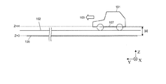
本発明の実施形態1における車両用充給電システムは、走行中の車両への充電、給電のうち少なくとも一方を行う走行中充給電システム、または駐車中の車両への充電、給電のうち少なくとも一方を行う駐車中充給電システムとして用いられる。なお、本明細書において、「充電」とは車両内に設けられた二次電池を充電し車両を駆動するための電力を蓄えることを指す。また、「給電」とは車載の駆動用電気モータなどの負荷に電力を供給することを指す。本実施形態の車両用充給電システムは、路面上または路面下に設けられた送電アンテナと、車両に設けられた受電アンテナとを備えている。送電アンテナと受電アンテナとが共振磁界結合することにより、無線で電力が伝送される。
(式1) L1>L2
(式2) W1>W2
(式3) X0=(W1−W2)/2
(式4) −X0≦X≦X0
(式5) FTx=ZTx1/ZTx0
(式6) FRx=ZRx1/ZRx0
(式7) 0.11×W1≦H≦0.26×W1
(式8) 0.12×W1≦H≦0.22×W1
(式9) 0.15×W1≦H≦0.19×W1

(式10)VRi_1=VRi_0×(FRx)^0.5
102 路面
103 車両進行方向
105 送電アンテナ
107 受電アンテナ
112 電源
114 発振部
116 整流部
117 電源制御部
118 負荷
119 周波数変換部
120 二次電池
122 送電部
124 受電部
Claims (21)
- 路面上または路面下に設けられた少なくとも1つの送電アンテナと、少なくとも1台の車両に設けられた受電アンテナとを含む車両用充給電システムであって、
前記送電アンテナおよび前記受電アンテナは、共振磁界によって互いに結合する共振器対であり、
車両進行方向をY方向、前記車両進行方向に垂直な方向をX方向とするとき、
前記送電アンテナのY方向の長さおよびX方向の長さは、それぞれ、前記受電アンテナのY方向の長さおよびX方向の長さよりも大きく、
前記送電アンテナのX方向の長さをW1、前記送電アンテナと前記受電アンテナの対向距離をHとするとき、
0.11×W1≦H≦0.26×W1
を満足し、
前記送電アンテナと前記受電アンテナとが対向するときに前記送電アンテナから前記受電アンテナに非接触で電力を供給する車両用充給電システム。 - 0.12×W1≦H≦0.22×W1
を満足する請求項1に記載の車両用充給電システム。 - 0.15×W1≦H≦0.19×W1
を満足する請求項2に記載の車両用充給電システム。 - 電源から受けとったエネルギをRFエネルギに変換して前記送電アンテナに送出する発振部を有し、
前記車両は、前記受電アンテナが前記送電アンテナから受けとったRFエネルギを直流エネルギまたは前記RFエネルギよりも周波数の低い交流エネルギに変換して出力する電力変換部を有する請求項1から3のいずれかに記載の車両用充給電システム。 - 前記送電アンテナと前記受電アンテナとの間の伝送効率を最大化する前記送電アンテナの入力インピーダンスは、前記発振部の出力インピーダンスと一致する請求項4に記載の車両用充給電システム。
- 前記送電アンテナと前記受電アンテナとの間の伝送効率を最大化する前記受電アンテナの出力インピーダンスは、前記電力変換部の入力インピーダンスと一致する請求項4または5に記載の車両用充給電システム。
- 前記車両は、前記電力変換部が出力する前記直流エネルギまたは前記交流エネルギによって動作する負荷を有している、請求項4から6のいずれかに記載の車両用充給電システム。
- 前記負荷の入力インピーダンスは、前記電力変換部の出力インピーダンスと一致する請求項7に記載の車両用充給電システム。
- 前記少なくとも1つの送電アンテナは、第1の送電アンテナと第2の送電アンテナとを含み、
前記第1の送電アンテナと前記受電アンテナとの間の結合係数は、前記第2の送電アンテナと前記受電アンテナとの間の結合係数と異なっており、
前記第1の送電アンテナと前記受電アンテナとが電力伝送を行うときの前記負荷の入力電圧は、前記第2の送電アンテナと前記受電アンテナとが電力伝送を行うときの前記負荷の入力電圧とほぼ等しくなるように設計されている、請求項7または8に記載の車両用充給電システム。 - 前記車両は、二次電池を有し、
前記受電アンテナが前記送電アンテナから受け取ったエネルギによって前記二次電池を充電する請求項1から9のいずれかに記載の車両用充給電システム。 - 前記路面に垂直な方向から見たとき、前記受電アンテナの中心部は、前記車両の前記X方向における中心線付近に位置している、請求項1から10のいずれかに記載の車両用充給電システム。
- 前記路面に垂直な方向から見たとき、前記受電アンテナの中心部は、前記車両の前記Y方向における中心線付近に位置している、請求項1から11のいずれかに記載の車両用充給電システム。
- 前記送電アンテナのY方向の長さは、前記車両のY方向の長さとほぼ等しい、請求項1から12のいずれかに記載の車両用充給電システム。
- 前記送電アンテナのY方向の長さは、前記車両のY方向の長さよりも大きい請求項1から12のいずれかに記載の車両用充給電システム。
- 前記路面に垂直な方向から見たとき、前記送電アンテナの中心部は、走行レーンの前記X方向における中心線付近に位置している、請求項1から14のいずれかに記載の車両用充給電システム。
- 前記少なくとも1つの送電アンテナは、Y方向に沿って配列された複数の送電アンテナを含み、
前記車両の移動に伴って前記受電アンテナが前記複数の送電アンテナの各々と対向するとき、前記受電アンテナに対向する送電アンテナから前記受電アンテナに順次電力伝送を行う請求項1から15のいずれかに記載の車両用充給電システム。 - 請求項1から16のいずれかに記載の車両用充給電システムに使用される車両であって、
前記受電アンテナと、
前記受電アンテナが前記送電アンテナから受け取ったエネルギによって動作する負荷と、
を有する車両。 - 前記負荷は、電気モータである、請求項17に記載の車両。
- 内燃機関を動力源とする、請求項17または18に記載の車両。
- 請求項1から16のいずれかに記載の車両用充給電システムに使用される送電アンテナ。
- 請求項1から16のいずれかに記載の車両用充給電システムに使用される受電アンテナと、
前記受電アンテナが前記送電アンテナから受け取ったRFエネルギを直流エネルギまたは前記RFエネルギよりも周波数の低い交流エネルギに変換して出力する電力変換部とを備える受電システム。
Applications Claiming Priority (2)
| Application Number | Priority Date | Filing Date | Title |
|---|---|---|---|
| US26093709P | 2009-11-13 | 2009-11-13 | |
| US61/260,937 | 2009-11-13 |
Related Child Applications (1)
| Application Number | Title | Priority Date | Filing Date |
|---|---|---|---|
| JP2016015340A Division JP6179826B2 (ja) | 2009-11-13 | 2016-01-29 | 車両用充給電システム |
Publications (2)
| Publication Number | Publication Date |
|---|---|
| JP2011109902A JP2011109902A (ja) | 2011-06-02 |
| JP5909714B2 true JP5909714B2 (ja) | 2016-04-27 |
Family
ID=43558293
Family Applications (2)
| Application Number | Title | Priority Date | Filing Date |
|---|---|---|---|
| JP2010252236A Active JP5909714B2 (ja) | 2009-11-13 | 2010-11-10 | 車両用充給電システム |
| JP2016015340A Active JP6179826B2 (ja) | 2009-11-13 | 2016-01-29 | 車両用充給電システム |
Family Applications After (1)
| Application Number | Title | Priority Date | Filing Date |
|---|---|---|---|
| JP2016015340A Active JP6179826B2 (ja) | 2009-11-13 | 2016-01-29 | 車両用充給電システム |
Country Status (5)
| Country | Link |
|---|---|
| US (1) | US8552685B2 (ja) |
| EP (1) | EP2465179B1 (ja) |
| JP (2) | JP5909714B2 (ja) |
| CN (2) | CN105305657B (ja) |
| WO (1) | WO2011059108A1 (ja) |
Families Citing this family (204)
| Publication number | Priority date | Publication date | Assignee | Title |
|---|---|---|---|---|
| US20160043571A1 (en) * | 2008-09-27 | 2016-02-11 | Witricity Corporation | Resonator enclosure |
| GB2476497A (en) * | 2009-12-23 | 2011-06-29 | Bombardier Transp Gmbh | Transferring electromagnetic energy to a vehicle |
| US20110302078A1 (en) | 2010-06-02 | 2011-12-08 | Bryan Marc Failing | Managing an energy transfer between a vehicle and an energy transfer system |
| US9143010B2 (en) * | 2010-12-28 | 2015-09-22 | Tdk Corporation | Wireless power transmission system for selectively powering one or more of a plurality of receivers |
| JP5338851B2 (ja) * | 2011-05-23 | 2013-11-13 | 株式会社デンソー | 車両用電力送受電システム |
| KR101573347B1 (ko) * | 2011-09-09 | 2015-12-01 | 쥬코쿠 덴료쿠 가부시키 가이샤 | 비접촉 급전 시스템 및 비접촉 급전 방법 |
| DE102011088973A1 (de) * | 2011-12-19 | 2013-06-20 | Robert Bosch Gmbh | Verfahren und Vorrichtung zum Anpassen einer Spannungsgrenze in einem Bordnetz |
| GB201121938D0 (en) * | 2011-12-21 | 2012-02-01 | Dames Andrew N | Supply of grid power to moving vehicles |
| JP2013223262A (ja) * | 2012-04-12 | 2013-10-28 | Hitachi Cable Ltd | 共鳴型非接触給電システム |
| US10263432B1 (en) | 2013-06-25 | 2019-04-16 | Energous Corporation | Multi-mode transmitter with an antenna array for delivering wireless power and providing Wi-Fi access |
| US9124125B2 (en) | 2013-05-10 | 2015-09-01 | Energous Corporation | Wireless power transmission with selective range |
| US9876379B1 (en) | 2013-07-11 | 2018-01-23 | Energous Corporation | Wireless charging and powering of electronic devices in a vehicle |
| US9867062B1 (en) | 2014-07-21 | 2018-01-09 | Energous Corporation | System and methods for using a remote server to authorize a receiving device that has requested wireless power and to determine whether another receiving device should request wireless power in a wireless power transmission system |
| US10050462B1 (en) | 2013-08-06 | 2018-08-14 | Energous Corporation | Social power sharing for mobile devices based on pocket-forming |
| US10243414B1 (en) | 2014-05-07 | 2019-03-26 | Energous Corporation | Wearable device with wireless power and payload receiver |
| US10218227B2 (en) | 2014-05-07 | 2019-02-26 | Energous Corporation | Compact PIFA antenna |
| US10128693B2 (en) | 2014-07-14 | 2018-11-13 | Energous Corporation | System and method for providing health safety in a wireless power transmission system |
| US10211674B1 (en) | 2013-06-12 | 2019-02-19 | Energous Corporation | Wireless charging using selected reflectors |
| US9954374B1 (en) | 2014-05-23 | 2018-04-24 | Energous Corporation | System and method for self-system analysis for detecting a fault in a wireless power transmission Network |
| US9893555B1 (en) | 2013-10-10 | 2018-02-13 | Energous Corporation | Wireless charging of tools using a toolbox transmitter |
| US9847677B1 (en) | 2013-10-10 | 2017-12-19 | Energous Corporation | Wireless charging and powering of healthcare gadgets and sensors |
| US9806564B2 (en) | 2014-05-07 | 2017-10-31 | Energous Corporation | Integrated rectifier and boost converter for wireless power transmission |
| US10965164B2 (en) | 2012-07-06 | 2021-03-30 | Energous Corporation | Systems and methods of wirelessly delivering power to a receiver device |
| US9368020B1 (en) | 2013-05-10 | 2016-06-14 | Energous Corporation | Off-premises alert system and method for wireless power receivers in a wireless power network |
| US9887739B2 (en) | 2012-07-06 | 2018-02-06 | Energous Corporation | Systems and methods for wireless power transmission by comparing voltage levels associated with power waves transmitted by antennas of a plurality of antennas of a transmitter to determine appropriate phase adjustments for the power waves |
| US10256657B2 (en) | 2015-12-24 | 2019-04-09 | Energous Corporation | Antenna having coaxial structure for near field wireless power charging |
| US10291055B1 (en) | 2014-12-29 | 2019-05-14 | Energous Corporation | Systems and methods for controlling far-field wireless power transmission based on battery power levels of a receiving device |
| US9825674B1 (en) | 2014-05-23 | 2017-11-21 | Energous Corporation | Enhanced transmitter that selects configurations of antenna elements for performing wireless power transmission and receiving functions |
| US9948135B2 (en) | 2015-09-22 | 2018-04-17 | Energous Corporation | Systems and methods for identifying sensitive objects in a wireless charging transmission field |
| US9893768B2 (en) | 2012-07-06 | 2018-02-13 | Energous Corporation | Methodology for multiple pocket-forming |
| US10063105B2 (en) | 2013-07-11 | 2018-08-28 | Energous Corporation | Proximity transmitters for wireless power charging systems |
| US9824815B2 (en) | 2013-05-10 | 2017-11-21 | Energous Corporation | Wireless charging and powering of healthcare gadgets and sensors |
| US10992187B2 (en) | 2012-07-06 | 2021-04-27 | Energous Corporation | System and methods of using electromagnetic waves to wirelessly deliver power to electronic devices |
| US10223717B1 (en) | 2014-05-23 | 2019-03-05 | Energous Corporation | Systems and methods for payment-based authorization of wireless power transmission service |
| US9843201B1 (en) | 2012-07-06 | 2017-12-12 | Energous Corporation | Wireless power transmitter that selects antenna sets for transmitting wireless power to a receiver based on location of the receiver, and methods of use thereof |
| US9438045B1 (en) | 2013-05-10 | 2016-09-06 | Energous Corporation | Methods and systems for maximum power point transfer in receivers |
| US9887584B1 (en) | 2014-08-21 | 2018-02-06 | Energous Corporation | Systems and methods for a configuration web service to provide configuration of a wireless power transmitter within a wireless power transmission system |
| US10224758B2 (en) | 2013-05-10 | 2019-03-05 | Energous Corporation | Wireless powering of electronic devices with selective delivery range |
| US9906065B2 (en) | 2012-07-06 | 2018-02-27 | Energous Corporation | Systems and methods of transmitting power transmission waves based on signals received at first and second subsets of a transmitter's antenna array |
| US9941707B1 (en) | 2013-07-19 | 2018-04-10 | Energous Corporation | Home base station for multiple room coverage with multiple transmitters |
| US9941747B2 (en) | 2014-07-14 | 2018-04-10 | Energous Corporation | System and method for manually selecting and deselecting devices to charge in a wireless power network |
| US9882430B1 (en) | 2014-05-07 | 2018-01-30 | Energous Corporation | Cluster management of transmitters in a wireless power transmission system |
| US10199849B1 (en) | 2014-08-21 | 2019-02-05 | Energous Corporation | Method for automatically testing the operational status of a wireless power receiver in a wireless power transmission system |
| US9831718B2 (en) | 2013-07-25 | 2017-11-28 | Energous Corporation | TV with integrated wireless power transmitter |
| US9893554B2 (en) | 2014-07-14 | 2018-02-13 | Energous Corporation | System and method for providing health safety in a wireless power transmission system |
| US9847679B2 (en) | 2014-05-07 | 2017-12-19 | Energous Corporation | System and method for controlling communication between wireless power transmitter managers |
| US10291066B1 (en) | 2014-05-07 | 2019-05-14 | Energous Corporation | Power transmission control systems and methods |
| US10186913B2 (en) | 2012-07-06 | 2019-01-22 | Energous Corporation | System and methods for pocket-forming based on constructive and destructive interferences to power one or more wireless power receivers using a wireless power transmitter including a plurality of antennas |
| US9939864B1 (en) | 2014-08-21 | 2018-04-10 | Energous Corporation | System and method to control a wireless power transmission system by configuration of wireless power transmission control parameters |
| US9838083B2 (en) | 2014-07-21 | 2017-12-05 | Energous Corporation | Systems and methods for communication with remote management systems |
| US10211682B2 (en) | 2014-05-07 | 2019-02-19 | Energous Corporation | Systems and methods for controlling operation of a transmitter of a wireless power network based on user instructions received from an authenticated computing device powered or charged by a receiver of the wireless power network |
| US10124754B1 (en) | 2013-07-19 | 2018-11-13 | Energous Corporation | Wireless charging and powering of electronic sensors in a vehicle |
| US10230266B1 (en) | 2014-02-06 | 2019-03-12 | Energous Corporation | Wireless power receivers that communicate status data indicating wireless power transmission effectiveness with a transmitter using a built-in communications component of a mobile device, and methods of use thereof |
| US10270261B2 (en) | 2015-09-16 | 2019-04-23 | Energous Corporation | Systems and methods of object detection in wireless power charging systems |
| US11502551B2 (en) | 2012-07-06 | 2022-11-15 | Energous Corporation | Wirelessly charging multiple wireless-power receivers using different subsets of an antenna array to focus energy at different locations |
| US10038337B1 (en) | 2013-09-16 | 2018-07-31 | Energous Corporation | Wireless power supply for rescue devices |
| US20140008993A1 (en) | 2012-07-06 | 2014-01-09 | DvineWave Inc. | Methodology for pocket-forming |
| US9787103B1 (en) | 2013-08-06 | 2017-10-10 | Energous Corporation | Systems and methods for wirelessly delivering power to electronic devices that are unable to communicate with a transmitter |
| US9859797B1 (en) | 2014-05-07 | 2018-01-02 | Energous Corporation | Synchronous rectifier design for wireless power receiver |
| US10992185B2 (en) | 2012-07-06 | 2021-04-27 | Energous Corporation | Systems and methods of using electromagnetic waves to wirelessly deliver power to game controllers |
| US9876394B1 (en) | 2014-05-07 | 2018-01-23 | Energous Corporation | Boost-charger-boost system for enhanced power delivery |
| US9882427B2 (en) | 2013-05-10 | 2018-01-30 | Energous Corporation | Wireless power delivery using a base station to control operations of a plurality of wireless power transmitters |
| US10193396B1 (en) | 2014-05-07 | 2019-01-29 | Energous Corporation | Cluster management of transmitters in a wireless power transmission system |
| US10206185B2 (en) | 2013-05-10 | 2019-02-12 | Energous Corporation | System and methods for wireless power transmission to an electronic device in accordance with user-defined restrictions |
| US10128699B2 (en) | 2014-07-14 | 2018-11-13 | Energous Corporation | Systems and methods of providing wireless power using receiver device sensor inputs |
| US9891669B2 (en) | 2014-08-21 | 2018-02-13 | Energous Corporation | Systems and methods for a configuration web service to provide configuration of a wireless power transmitter within a wireless power transmission system |
| US9843213B2 (en) | 2013-08-06 | 2017-12-12 | Energous Corporation | Social power sharing for mobile devices based on pocket-forming |
| US9859757B1 (en) | 2013-07-25 | 2018-01-02 | Energous Corporation | Antenna tile arrangements in electronic device enclosures |
| US9252628B2 (en) | 2013-05-10 | 2016-02-02 | Energous Corporation | Laptop computer as a transmitter for wireless charging |
| US9876648B2 (en) | 2014-08-21 | 2018-01-23 | Energous Corporation | System and method to control a wireless power transmission system by configuration of wireless power transmission control parameters |
| US9853692B1 (en) | 2014-05-23 | 2017-12-26 | Energous Corporation | Systems and methods for wireless power transmission |
| US10211680B2 (en) | 2013-07-19 | 2019-02-19 | Energous Corporation | Method for 3 dimensional pocket-forming |
| US10141791B2 (en) | 2014-05-07 | 2018-11-27 | Energous Corporation | Systems and methods for controlling communications during wireless transmission of power using application programming interfaces |
| US9871398B1 (en) | 2013-07-01 | 2018-01-16 | Energous Corporation | Hybrid charging method for wireless power transmission based on pocket-forming |
| US9143000B2 (en) | 2012-07-06 | 2015-09-22 | Energous Corporation | Portable wireless charging pad |
| US10090886B1 (en) | 2014-07-14 | 2018-10-02 | Energous Corporation | System and method for enabling automatic charging schedules in a wireless power network to one or more devices |
| US9899873B2 (en) | 2014-05-23 | 2018-02-20 | Energous Corporation | System and method for generating a power receiver identifier in a wireless power network |
| US10008889B2 (en) | 2014-08-21 | 2018-06-26 | Energous Corporation | Method for automatically testing the operational status of a wireless power receiver in a wireless power transmission system |
| US20150326070A1 (en) | 2014-05-07 | 2015-11-12 | Energous Corporation | Methods and Systems for Maximum Power Point Transfer in Receivers |
| US10090699B1 (en) | 2013-11-01 | 2018-10-02 | Energous Corporation | Wireless powered house |
| US10205239B1 (en) | 2014-05-07 | 2019-02-12 | Energous Corporation | Compact PIFA antenna |
| US9900057B2 (en) | 2012-07-06 | 2018-02-20 | Energous Corporation | Systems and methods for assigning groups of antenas of a wireless power transmitter to different wireless power receivers, and determining effective phases to use for wirelessly transmitting power using the assigned groups of antennas |
| US10063064B1 (en) | 2014-05-23 | 2018-08-28 | Energous Corporation | System and method for generating a power receiver identifier in a wireless power network |
| US9973021B2 (en) | 2012-07-06 | 2018-05-15 | Energous Corporation | Receivers for wireless power transmission |
| US9991741B1 (en) | 2014-07-14 | 2018-06-05 | Energous Corporation | System for tracking and reporting status and usage information in a wireless power management system |
| US9923386B1 (en) | 2012-07-06 | 2018-03-20 | Energous Corporation | Systems and methods for wireless power transmission by modifying a number of antenna elements used to transmit power waves to a receiver |
| US10075008B1 (en) | 2014-07-14 | 2018-09-11 | Energous Corporation | Systems and methods for manually adjusting when receiving electronic devices are scheduled to receive wirelessly delivered power from a wireless power transmitter in a wireless power network |
| US10439448B2 (en) | 2014-08-21 | 2019-10-08 | Energous Corporation | Systems and methods for automatically testing the communication between wireless power transmitter and wireless power receiver |
| US10063106B2 (en) | 2014-05-23 | 2018-08-28 | Energous Corporation | System and method for a self-system analysis in a wireless power transmission network |
| US10103582B2 (en) | 2012-07-06 | 2018-10-16 | Energous Corporation | Transmitters for wireless power transmission |
| US10381880B2 (en) | 2014-07-21 | 2019-08-13 | Energous Corporation | Integrated antenna structure arrays for wireless power transmission |
| US10224982B1 (en) | 2013-07-11 | 2019-03-05 | Energous Corporation | Wireless power transmitters for transmitting wireless power and tracking whether wireless power receivers are within authorized locations |
| US9859756B2 (en) | 2012-07-06 | 2018-01-02 | Energous Corporation | Transmittersand methods for adjusting wireless power transmission based on information from receivers |
| US10141768B2 (en) | 2013-06-03 | 2018-11-27 | Energous Corporation | Systems and methods for maximizing wireless power transfer efficiency by instructing a user to change a receiver device's position |
| US9941754B2 (en) | 2012-07-06 | 2018-04-10 | Energous Corporation | Wireless power transmission with selective range |
| US10312715B2 (en) | 2015-09-16 | 2019-06-04 | Energous Corporation | Systems and methods for wireless power charging |
| US9793758B2 (en) * | 2014-05-23 | 2017-10-17 | Energous Corporation | Enhanced transmitter using frequency control for wireless power transmission |
| US9853458B1 (en) | 2014-05-07 | 2017-12-26 | Energous Corporation | Systems and methods for device and power receiver pairing |
| US10199835B2 (en) | 2015-12-29 | 2019-02-05 | Energous Corporation | Radar motion detection using stepped frequency in wireless power transmission system |
| US9812890B1 (en) | 2013-07-11 | 2017-11-07 | Energous Corporation | Portable wireless charging pad |
| US9966765B1 (en) | 2013-06-25 | 2018-05-08 | Energous Corporation | Multi-mode transmitter |
| US9899861B1 (en) | 2013-10-10 | 2018-02-20 | Energous Corporation | Wireless charging methods and systems for game controllers, based on pocket-forming |
| US10148097B1 (en) | 2013-11-08 | 2018-12-04 | Energous Corporation | Systems and methods for using a predetermined number of communication channels of a wireless power transmitter to communicate with different wireless power receivers |
| US9912199B2 (en) | 2012-07-06 | 2018-03-06 | Energous Corporation | Receivers for wireless power transmission |
| JP6043462B2 (ja) | 2012-09-27 | 2016-12-14 | Ihi運搬機械株式会社 | 車両給電装置 |
| JP5924496B2 (ja) * | 2012-10-31 | 2016-05-25 | 株式会社エクォス・リサーチ | 電力伝送システム |
| CN103866729B (zh) * | 2012-12-13 | 2016-08-24 | 芜湖爱瑞特环保科技有限公司 | 一种磁耦合远距离高效传输机器人洗地机 |
| CN103866723A (zh) * | 2012-12-13 | 2014-06-18 | 芜湖爱瑞特环保科技有限公司 | 一种磁耦合远距离高效传输机器人扫地车 |
| CN103966962B (zh) * | 2013-01-29 | 2016-08-03 | 芜湖爱瑞特环保科技有限公司 | 磁耦合远距离高效传输机器人擦地机 |
| JP6273616B2 (ja) * | 2013-02-19 | 2018-02-07 | パナソニックIpマネジメント株式会社 | 異物検出装置および非接触充電システム |
| US9866279B2 (en) | 2013-05-10 | 2018-01-09 | Energous Corporation | Systems and methods for selecting which power transmitter should deliver wireless power to a receiving device in a wireless power delivery network |
| US9819230B2 (en) | 2014-05-07 | 2017-11-14 | Energous Corporation | Enhanced receiver for wireless power transmission |
| US9537357B2 (en) | 2013-05-10 | 2017-01-03 | Energous Corporation | Wireless sound charging methods and systems for game controllers, based on pocket-forming |
| US9538382B2 (en) | 2013-05-10 | 2017-01-03 | Energous Corporation | System and method for smart registration of wireless power receivers in a wireless power network |
| US9419443B2 (en) | 2013-05-10 | 2016-08-16 | Energous Corporation | Transducer sound arrangement for pocket-forming |
| US10103552B1 (en) | 2013-06-03 | 2018-10-16 | Energous Corporation | Protocols for authenticated wireless power transmission |
| US10003211B1 (en) | 2013-06-17 | 2018-06-19 | Energous Corporation | Battery life of portable electronic devices |
| US10021523B2 (en) | 2013-07-11 | 2018-07-10 | Energous Corporation | Proximity transmitters for wireless power charging systems |
| US9979440B1 (en) | 2013-07-25 | 2018-05-22 | Energous Corporation | Antenna tile arrangements configured to operate as one functional unit |
| US10814729B2 (en) | 2013-11-14 | 2020-10-27 | Momentum Dynamics Corporation | Method and apparatus for the alignment of a vehicle and charging coil prior to wireless charging |
| US10040360B1 (en) * | 2013-11-14 | 2018-08-07 | Momentum Dynamics Corporation | Method and apparatus for the alignment of vehicles prior to wireless charging including a transmission line that leaks a signal for alignment |
| US11241970B2 (en) | 2013-11-14 | 2022-02-08 | Momentum Dynamics Corporation | Method and apparatus for the alignment of vehicles prior to wireless charging |
| US9935482B1 (en) | 2014-02-06 | 2018-04-03 | Energous Corporation | Wireless power transmitters that transmit at determined times based on power availability and consumption at a receiving mobile device |
| US10075017B2 (en) | 2014-02-06 | 2018-09-11 | Energous Corporation | External or internal wireless power receiver with spaced-apart antenna elements for charging or powering mobile devices using wirelessly delivered power |
| US9966784B2 (en) | 2014-06-03 | 2018-05-08 | Energous Corporation | Systems and methods for extending battery life of portable electronic devices charged by sound |
| US10158257B2 (en) | 2014-05-01 | 2018-12-18 | Energous Corporation | System and methods for using sound waves to wirelessly deliver power to electronic devices |
| US9800172B1 (en) | 2014-05-07 | 2017-10-24 | Energous Corporation | Integrated rectifier and boost converter for boosting voltage received from wireless power transmission waves |
| US10153645B1 (en) | 2014-05-07 | 2018-12-11 | Energous Corporation | Systems and methods for designating a master power transmitter in a cluster of wireless power transmitters |
| US9973008B1 (en) | 2014-05-07 | 2018-05-15 | Energous Corporation | Wireless power receiver with boost converters directly coupled to a storage element |
| US10170917B1 (en) | 2014-05-07 | 2019-01-01 | Energous Corporation | Systems and methods for managing and controlling a wireless power network by establishing time intervals during which receivers communicate with a transmitter |
| US10153653B1 (en) | 2014-05-07 | 2018-12-11 | Energous Corporation | Systems and methods for using application programming interfaces to control communications between a transmitter and a receiver |
| US9876536B1 (en) | 2014-05-23 | 2018-01-23 | Energous Corporation | Systems and methods for assigning groups of antennas to transmit wireless power to different wireless power receivers |
| US10068703B1 (en) | 2014-07-21 | 2018-09-04 | Energous Corporation | Integrated miniature PIFA with artificial magnetic conductor metamaterials |
| US9871301B2 (en) | 2014-07-21 | 2018-01-16 | Energous Corporation | Integrated miniature PIFA with artificial magnetic conductor metamaterials |
| US10116143B1 (en) | 2014-07-21 | 2018-10-30 | Energous Corporation | Integrated antenna arrays for wireless power transmission |
| US9917477B1 (en) | 2014-08-21 | 2018-03-13 | Energous Corporation | Systems and methods for automatically testing the communication between power transmitter and wireless receiver |
| US9965009B1 (en) | 2014-08-21 | 2018-05-08 | Energous Corporation | Systems and methods for assigning a power receiver to individual power transmitters based on location of the power receiver |
| US10122415B2 (en) | 2014-12-27 | 2018-11-06 | Energous Corporation | Systems and methods for assigning a set of antennas of a wireless power transmitter to a wireless power receiver based on a location of the wireless power receiver |
| US9893535B2 (en) | 2015-02-13 | 2018-02-13 | Energous Corporation | Systems and methods for determining optimal charging positions to maximize efficiency of power received from wirelessly delivered sound wave energy |
| US9906275B2 (en) | 2015-09-15 | 2018-02-27 | Energous Corporation | Identifying receivers in a wireless charging transmission field |
| US10523033B2 (en) | 2015-09-15 | 2019-12-31 | Energous Corporation | Receiver devices configured to determine location within a transmission field |
| US9871387B1 (en) | 2015-09-16 | 2018-01-16 | Energous Corporation | Systems and methods of object detection using one or more video cameras in wireless power charging systems |
| US9941752B2 (en) | 2015-09-16 | 2018-04-10 | Energous Corporation | Systems and methods of object detection in wireless power charging systems |
| US10778041B2 (en) | 2015-09-16 | 2020-09-15 | Energous Corporation | Systems and methods for generating power waves in a wireless power transmission system |
| US11710321B2 (en) | 2015-09-16 | 2023-07-25 | Energous Corporation | Systems and methods of object detection in wireless power charging systems |
| US9893538B1 (en) | 2015-09-16 | 2018-02-13 | Energous Corporation | Systems and methods of object detection in wireless power charging systems |
| US10186893B2 (en) | 2015-09-16 | 2019-01-22 | Energous Corporation | Systems and methods for real time or near real time wireless communications between a wireless power transmitter and a wireless power receiver |
| US10008875B1 (en) | 2015-09-16 | 2018-06-26 | Energous Corporation | Wireless power transmitter configured to transmit power waves to a predicted location of a moving wireless power receiver |
| US10211685B2 (en) | 2015-09-16 | 2019-02-19 | Energous Corporation | Systems and methods for real or near real time wireless communications between a wireless power transmitter and a wireless power receiver |
| US10158259B1 (en) | 2015-09-16 | 2018-12-18 | Energous Corporation | Systems and methods for identifying receivers in a transmission field by transmitting exploratory power waves towards different segments of a transmission field |
| US10199850B2 (en) | 2015-09-16 | 2019-02-05 | Energous Corporation | Systems and methods for wirelessly transmitting power from a transmitter to a receiver by determining refined locations of the receiver in a segmented transmission field associated with the transmitter |
| CN108028549B (zh) * | 2015-09-18 | 2022-04-19 | 株式会社富士 | 非接触供电装置 |
| US10135295B2 (en) | 2015-09-22 | 2018-11-20 | Energous Corporation | Systems and methods for nullifying energy levels for wireless power transmission waves |
| US10027168B2 (en) | 2015-09-22 | 2018-07-17 | Energous Corporation | Systems and methods for generating and transmitting wireless power transmission waves using antennas having a spacing that is selected by the transmitter |
| US10033222B1 (en) | 2015-09-22 | 2018-07-24 | Energous Corporation | Systems and methods for determining and generating a waveform for wireless power transmission waves |
| US10020678B1 (en) | 2015-09-22 | 2018-07-10 | Energous Corporation | Systems and methods for selecting antennas to generate and transmit power transmission waves |
| US10128686B1 (en) | 2015-09-22 | 2018-11-13 | Energous Corporation | Systems and methods for identifying receiver locations using sensor technologies |
| US10050470B1 (en) | 2015-09-22 | 2018-08-14 | Energous Corporation | Wireless power transmission device having antennas oriented in three dimensions |
| US10153660B1 (en) | 2015-09-22 | 2018-12-11 | Energous Corporation | Systems and methods for preconfiguring sensor data for wireless charging systems |
| US10135294B1 (en) | 2015-09-22 | 2018-11-20 | Energous Corporation | Systems and methods for preconfiguring transmission devices for power wave transmissions based on location data of one or more receivers |
| US10734717B2 (en) | 2015-10-13 | 2020-08-04 | Energous Corporation | 3D ceramic mold antenna |
| US10333332B1 (en) | 2015-10-13 | 2019-06-25 | Energous Corporation | Cross-polarized dipole antenna |
| US9899744B1 (en) | 2015-10-28 | 2018-02-20 | Energous Corporation | Antenna for wireless charging systems |
| US9853485B2 (en) | 2015-10-28 | 2017-12-26 | Energous Corporation | Antenna for wireless charging systems |
| US10063108B1 (en) | 2015-11-02 | 2018-08-28 | Energous Corporation | Stamped three-dimensional antenna |
| US10027180B1 (en) | 2015-11-02 | 2018-07-17 | Energous Corporation | 3D triple linear antenna that acts as heat sink |
| US10135112B1 (en) | 2015-11-02 | 2018-11-20 | Energous Corporation | 3D antenna mount |
| US10632852B2 (en) | 2015-11-13 | 2020-04-28 | Nio Usa, Inc. | Electric vehicle optical charging system and method of use |
| US10220717B2 (en) * | 2015-11-13 | 2019-03-05 | Nio Usa, Inc. | Electric vehicle emergency charging system and method of use |
| US10532663B2 (en) | 2015-11-13 | 2020-01-14 | Nio Usa, Inc. | Electric vehicle overhead charging system and method of use |
| CN105406563B (zh) * | 2015-11-24 | 2018-04-24 | 东南大学 | 一种电动汽车动态无线供电系统分段发射线圈切换方法 |
| US10320446B2 (en) | 2015-12-24 | 2019-06-11 | Energous Corporation | Miniaturized highly-efficient designs for near-field power transfer system |
| US10256677B2 (en) | 2016-12-12 | 2019-04-09 | Energous Corporation | Near-field RF charging pad with adaptive loading to efficiently charge an electronic device at any position on the pad |
| US11863001B2 (en) | 2015-12-24 | 2024-01-02 | Energous Corporation | Near-field antenna for wireless power transmission with antenna elements that follow meandering patterns |
| US10038332B1 (en) | 2015-12-24 | 2018-07-31 | Energous Corporation | Systems and methods of wireless power charging through multiple receiving devices |
| US10141771B1 (en) | 2015-12-24 | 2018-11-27 | Energous Corporation | Near field transmitters with contact points for wireless power charging |
| US10027159B2 (en) | 2015-12-24 | 2018-07-17 | Energous Corporation | Antenna for transmitting wireless power signals |
| US10079515B2 (en) | 2016-12-12 | 2018-09-18 | Energous Corporation | Near-field RF charging pad with multi-band antenna element with adaptive loading to efficiently charge an electronic device at any position on the pad |
| US10008886B2 (en) | 2015-12-29 | 2018-06-26 | Energous Corporation | Modular antennas with heat sinks in wireless power transmission systems |
| JP6868841B2 (ja) * | 2016-02-19 | 2021-05-12 | パナソニックIpマネジメント株式会社 | 電動装置 |
| EP3466743A4 (en) * | 2016-05-31 | 2020-01-01 | Nidec Corporation | MOBILE BODY AND MOBILE BODY SYSTEM |
| US10923954B2 (en) | 2016-11-03 | 2021-02-16 | Energous Corporation | Wireless power receiver with a synchronous rectifier |
| CN110235337A (zh) | 2016-12-12 | 2019-09-13 | 艾诺格思公司 | 选择性地激活近场充电垫的天线区域以最大化所传递无线功率的方法 |
| US10680319B2 (en) | 2017-01-06 | 2020-06-09 | Energous Corporation | Devices and methods for reducing mutual coupling effects in wireless power transmission systems |
| US10389161B2 (en) | 2017-03-15 | 2019-08-20 | Energous Corporation | Surface mount dielectric antennas for wireless power transmitters |
| US10439442B2 (en) | 2017-01-24 | 2019-10-08 | Energous Corporation | Microstrip antennas for wireless power transmitters |
| WO2018183892A1 (en) | 2017-03-30 | 2018-10-04 | Energous Corporation | Flat antennas having two or more resonant frequencies for use in wireless power transmission systems |
| US10511097B2 (en) | 2017-05-12 | 2019-12-17 | Energous Corporation | Near-field antennas for accumulating energy at a near-field distance with minimal far-field gain |
| US11462949B2 (en) | 2017-05-16 | 2022-10-04 | Wireless electrical Grid LAN, WiGL Inc | Wireless charging method and system |
| US10848853B2 (en) | 2017-06-23 | 2020-11-24 | Energous Corporation | Systems, methods, and devices for utilizing a wire of a sound-producing device as an antenna for receipt of wirelessly delivered power |
| WO2019000056A1 (en) * | 2017-06-28 | 2019-01-03 | Music Salih | ELECTRICITY WIRELESS TRANSMISSION SYSTEM FOR ELECTRIC VEHICLES |
| CN107399244B (zh) * | 2017-07-27 | 2020-12-04 | 许继电源有限公司 | 一种移动式车辆无线充电系统 |
| DE102017215864B3 (de) * | 2017-09-08 | 2019-03-07 | Audi Ag | Verfahren zum Regeln einer Sendeleistung für eine von einem Kraftfahrzeug ausgehende Funkverbindung, Regelvorrichtung für ein Kraftfahrzeug und Kraftfahrzeug mit Regelvorrichtung |
| US10122219B1 (en) | 2017-10-10 | 2018-11-06 | Energous Corporation | Systems, methods, and devices for using a battery as a antenna for receiving wirelessly delivered power from radio frequency power waves |
| US11342798B2 (en) | 2017-10-30 | 2022-05-24 | Energous Corporation | Systems and methods for managing coexistence of wireless-power signals and data signals operating in a same frequency band |
| US10615647B2 (en) | 2018-02-02 | 2020-04-07 | Energous Corporation | Systems and methods for detecting wireless power receivers and other objects at a near-field charging pad |
| US11159057B2 (en) | 2018-03-14 | 2021-10-26 | Energous Corporation | Loop antennas with selectively-activated feeds to control propagation patterns of wireless power signals |
| US11515732B2 (en) | 2018-06-25 | 2022-11-29 | Energous Corporation | Power wave transmission techniques to focus wirelessly delivered power at a receiving device |
| US11437735B2 (en) | 2018-11-14 | 2022-09-06 | Energous Corporation | Systems for receiving electromagnetic energy using antennas that are minimally affected by the presence of the human body |
| JP2022523022A (ja) | 2019-01-28 | 2022-04-21 | エナージャス コーポレイション | 無線送電のための小型アンテナ用のシステム及び方法 |
| KR20210123329A (ko) | 2019-02-06 | 2021-10-13 | 에너저스 코포레이션 | 안테나 어레이에 있어서의 개별 안테나들에 이용하기 위해 최적 위상을 추정하는 시스템 및 방법 |
| US11034252B2 (en) | 2019-07-31 | 2021-06-15 | Kristopher Barnes | Electric vehicle charging assembly |
| CN112868163A (zh) * | 2019-08-07 | 2021-05-28 | 华为技术有限公司 | 一种无线充电装置、位置检测的方法及系统 |
| WO2022030068A1 (ja) * | 2020-08-07 | 2022-02-10 | 株式会社Ihi | 送電装置、道路床版及び送電システム |
Family Cites Families (30)
| Publication number | Priority date | Publication date | Assignee | Title |
|---|---|---|---|---|
| US4836344A (en) * | 1987-05-08 | 1989-06-06 | Inductran Corporation | Roadway power and control system for inductively coupled transportation system |
| JPS6430403A (en) * | 1987-07-24 | 1989-02-01 | Hitachi Ltd | Electric automobile charger |
| JP2996559B2 (ja) * | 1992-01-29 | 2000-01-11 | 本田技研工業株式会社 | 電気自動車の充電状況表示システム |
| FR2695266B1 (fr) * | 1992-09-02 | 1994-09-30 | Cableco Sa | Ensemble pour recharger les batteries d'accumulateurs d'un véhicule automobile électrique. |
| DE4236286A1 (de) * | 1992-10-28 | 1994-05-05 | Daimler Benz Ag | Verfahren und Anordnung zum automatischen berührungslosen Laden |
| JPH0739007A (ja) * | 1993-07-22 | 1995-02-07 | Sumitomo Electric Ind Ltd | 走行車両の非接触集電装置 |
| JPH07170612A (ja) * | 1993-12-10 | 1995-07-04 | Fujitsu Ten Ltd | 電池充電システム |
| US5573090A (en) * | 1994-05-05 | 1996-11-12 | H. R. Ross Industries, Inc. | Raodway-powered electric vehicle system having onboard power metering and communication channel features |
| US20010015299A1 (en) * | 1995-01-30 | 2001-08-23 | Thomas S. Moore | Environmentally sensitive hybrid vehicle |
| JPH08237890A (ja) * | 1995-02-28 | 1996-09-13 | Fuji Electric Co Ltd | 自動車への非接触式電力供給装置 |
| EP0788212B1 (en) * | 1996-01-30 | 2002-04-17 | Sumitomo Wiring Systems, Ltd. | Connection system and connection method for an electric automotive vehicle |
| US5821728A (en) * | 1996-07-22 | 1998-10-13 | Schwind; John P. | Armature induction charging of moving electric vehicle batteries |
| JP2002508916A (ja) | 1997-05-06 | 2002-03-19 | オークランド ユニサービシズ リミテッド | 拡大ギャップを横切る誘導電力伝達 |
| JP3940939B2 (ja) * | 1997-09-08 | 2007-07-04 | 吉川アールエフシステム株式会社 | データキャリア |
| JP2002152996A (ja) | 2000-11-10 | 2002-05-24 | Toyota Motor Corp | 電力受給システム |
| JP3870315B2 (ja) * | 2001-08-08 | 2007-01-17 | 株式会社日立製作所 | 移動体システム |
| JP2006171967A (ja) * | 2004-12-14 | 2006-06-29 | Nissan Motor Co Ltd | マイクロ波電力伝送システム用のレーンマーカ装置 |
| DE102005007489A1 (de) | 2005-02-17 | 2006-08-24 | Siemens Ag | Holzbearbeitungsmaschine mit linearem Direktantrieb |
| US7451839B2 (en) * | 2005-05-24 | 2008-11-18 | Rearden, Llc | System and method for powering a vehicle using radio frequency generators |
| US7825543B2 (en) | 2005-07-12 | 2010-11-02 | Massachusetts Institute Of Technology | Wireless energy transfer |
| US7880337B2 (en) * | 2006-10-25 | 2011-02-01 | Laszlo Farkas | High power wireless resonant energy transfer system |
| JP4772744B2 (ja) * | 2007-05-17 | 2011-09-14 | 昭和飛行機工業株式会社 | 非接触給電装置用の信号伝送コイル通信装置 |
| US8030888B2 (en) * | 2007-08-13 | 2011-10-04 | Pandya Ravi A | Wireless charging system for vehicles |
| JP5414981B2 (ja) * | 2007-09-11 | 2014-02-12 | 昭和飛行機工業株式会社 | 移動式の非接触給電装置 |
| WO2009037821A1 (ja) * | 2007-09-17 | 2009-03-26 | Hideo Kikuchi | 誘導電力伝送回路 |
| WO2009042214A1 (en) * | 2007-09-26 | 2009-04-02 | Governing Dynamics, Llc | Self-charging electric vehicles and aircraft, and wireless energy distribution system |
| JP4453741B2 (ja) * | 2007-10-25 | 2010-04-21 | トヨタ自動車株式会社 | 電動車両および車両用給電装置 |
| JP5221111B2 (ja) * | 2007-11-29 | 2013-06-26 | メレアグロス株式会社 | 送電コイル、送電装置、受電コイル、受電装置、および電力伝送装置。 |
| JP5238420B2 (ja) * | 2008-09-11 | 2013-07-17 | 矢崎総業株式会社 | 車両用ワイヤレス充電システム |
| EP2330716B1 (en) * | 2008-09-19 | 2018-09-05 | Toyota Jidosha Kabushiki Kaisha | Noncontact power receiving apparatus and vehicle including the same |
-
2010
- 2010-11-10 JP JP2010252236A patent/JP5909714B2/ja active Active
- 2010-11-11 US US12/944,183 patent/US8552685B2/en active Active
- 2010-11-11 CN CN201510686348.5A patent/CN105305657B/zh active Active
- 2010-11-11 CN CN201080041108.5A patent/CN102648560B/zh active Active
- 2010-11-11 WO PCT/JP2010/070519 patent/WO2011059108A1/en active Application Filing
- 2010-11-11 EP EP10785540.5A patent/EP2465179B1/en active Active
-
2016
- 2016-01-29 JP JP2016015340A patent/JP6179826B2/ja active Active
Also Published As
| Publication number | Publication date |
|---|---|
| US20110114401A1 (en) | 2011-05-19 |
| CN102648560B (zh) | 2015-11-25 |
| EP2465179B1 (en) | 2013-06-26 |
| WO2011059108A1 (en) | 2011-05-19 |
| CN102648560A (zh) | 2012-08-22 |
| US8552685B2 (en) | 2013-10-08 |
| CN105305657B (zh) | 2017-09-08 |
| EP2465179A1 (en) | 2012-06-20 |
| JP2011109902A (ja) | 2011-06-02 |
| JP2016116449A (ja) | 2016-06-23 |
| JP6179826B2 (ja) | 2017-08-16 |
| CN105305657A (zh) | 2016-02-03 |
Similar Documents
| Publication | Publication Date | Title |
|---|---|---|
| JP6179826B2 (ja) | 車両用充給電システム | |
| JP5938719B2 (ja) | 車両用充給電システム | |
| JP5622518B2 (ja) | 電池パックを備えた電動機械および電源システム | |
| EP2848453B1 (en) | Vehicle comprising power reception coil | |
| US20150091511A1 (en) | Vehicle | |
| WO2014069445A1 (ja) | 電力伝送システム | |
| WO2013054399A1 (ja) | 送電装置、受電装置、および電力伝送システム | |
| JP2011200052A (ja) | 給電装置 | |
| JP2011167036A (ja) | 車両用給電装置および受電装置 | |
| CN103858315A (zh) | 受电装置、具备该受电装置的车辆以及电力传输系统 | |
| JP2013135491A (ja) | アンテナ | |
| CN105324913A (zh) | 电力传输系统 | |
| JP2013132171A (ja) | 送電装置、受電装置、および電力伝送システム | |
| JP2014197935A (ja) | 電力伝送システム | |
| JP2014093320A (ja) | 電力伝送システム | |
| WO2020122017A1 (ja) | 受電機器 | |
| JP2014093321A (ja) | 電力伝送システム | |
| JP2014093798A (ja) | 電力伝送システム |
Legal Events
| Date | Code | Title | Description |
|---|---|---|---|
| A621 | Written request for application examination |
Free format text: JAPANESE INTERMEDIATE CODE: A621 Effective date: 20130924 |
|
| A977 | Report on retrieval |
Free format text: JAPANESE INTERMEDIATE CODE: A971007 Effective date: 20140521 |
|
| A131 | Notification of reasons for refusal |
Free format text: JAPANESE INTERMEDIATE CODE: A131 Effective date: 20140603 |
|
| A521 | Request for written amendment filed |
Free format text: JAPANESE INTERMEDIATE CODE: A523 Effective date: 20140731 |
|
| A711 | Notification of change in applicant |
Free format text: JAPANESE INTERMEDIATE CODE: A711 Effective date: 20141007 |
|
| A131 | Notification of reasons for refusal |
Free format text: JAPANESE INTERMEDIATE CODE: A131 Effective date: 20150310 |
|
| A521 | Request for written amendment filed |
Free format text: JAPANESE INTERMEDIATE CODE: A523 Effective date: 20150507 |
|
| TRDD | Decision of grant or rejection written | ||
| A01 | Written decision to grant a patent or to grant a registration (utility model) |
Free format text: JAPANESE INTERMEDIATE CODE: A01 Effective date: 20160105 |
|
| A61 | First payment of annual fees (during grant procedure) |
Free format text: JAPANESE INTERMEDIATE CODE: A61 Effective date: 20160129 |
|
| R151 | Written notification of patent or utility model registration |
Ref document number: 5909714 Country of ref document: JP Free format text: JAPANESE INTERMEDIATE CODE: R151 |