EP3599530B1 - Kabinenfrontwandstruktur eines fahrzeugs - Google Patents
Kabinenfrontwandstruktur eines fahrzeugs Download PDFInfo
- Publication number
- EP3599530B1 EP3599530B1 EP19188432.9A EP19188432A EP3599530B1 EP 3599530 B1 EP3599530 B1 EP 3599530B1 EP 19188432 A EP19188432 A EP 19188432A EP 3599530 B1 EP3599530 B1 EP 3599530B1
- Authority
- EP
- European Patent Office
- Prior art keywords
- bracket
- dash panel
- vehicle
- dash
- accelerator
- Prior art date
- Legal status (The legal status is an assumption and is not a legal conclusion. Google has not performed a legal analysis and makes no representation as to the accuracy of the status listed.)
- Active
Links
Images
Classifications
-
- B—PERFORMING OPERATIONS; TRANSPORTING
- B62—LAND VEHICLES FOR TRAVELLING OTHERWISE THAN ON RAILS
- B62D—MOTOR VEHICLES; TRAILERS
- B62D25/00—Superstructure or monocoque structure sub-units; Parts or details thereof not otherwise provided for
- B62D25/08—Front or rear portions
-
- B—PERFORMING OPERATIONS; TRANSPORTING
- B62—LAND VEHICLES FOR TRAVELLING OTHERWISE THAN ON RAILS
- B62D—MOTOR VEHICLES; TRAILERS
- B62D25/00—Superstructure or monocoque structure sub-units; Parts or details thereof not otherwise provided for
- B62D25/08—Front or rear portions
- B62D25/14—Dashboards as superstructure sub-units
-
- G—PHYSICS
- G05—CONTROLLING; REGULATING
- G05G—CONTROL DEVICES OR SYSTEMS INSOFAR AS CHARACTERISED BY MECHANICAL FEATURES ONLY
- G05G1/00—Controlling members, e.g. knobs or handles; Assemblies or arrangements thereof; Indicating position of controlling members
- G05G1/30—Controlling members actuated by foot
- G05G1/36—Mounting units comprising an assembly of two or more pedals, e.g. for facilitating mounting
Definitions
- the present disclosure relates to a cabin front wall structure of a vehicle, and in particular relates to a portion of the structure to which an accelerator pedal and a brake pedal are attached.
- a dash panel is arranged as a cabin front wall of a vehicle between a cabin of the vehicle and an engine compartment in which an engine and other components are mounted.
- a wall portion in front of a driver seat is equipped with an accelerator pedal and a brake pedal which are attached to the dash panel via an accelerator bracket and a brake bracket, respectively.
- JP 2006-82585 A discloses a cabin front wall structure according to the preamble of claim 1, in which an accelerator bracket and a brake bracket are integrated into one part, and the integrated part is attached to a dash panel. This is intended to allow the dash panel to be commonly used among vehicles even though pedals are disposed at different locations in the vehicles, and accordingly improve versatility of the dash panel.
- the driver seat of a vehicle is equipped with a steering handle, and a steering column is arranged so as to pass through the dash panel.
- the dash panel has a through hole in which the steering column is inserted, which may result in a decrease in strength of the dash panel around the through hole.
- JP 2006-82585 A uses the integral bracket in which attachment regions of an accelerator pedal and a brake pedal are closely located. Accordingly, the bracket of JP 2006-82585 A cannot sufficiently reinforce the dash panel.
- FR 2 960 202 A1 discloses a main brake system elements mounting arrangement for electric vehicle with short front overhang
- JP 2008 269025 A discloses an adjustable pedal device for vehicle
- JP 2004 210100 A discloses a pedal front and rear position adjustment device of vehicle.
- a cabin front wall structure of a vehicle includes a dash panel constituting a cabin front wall of the vehicle, an accelerator bracket attached to the dash panel, and used for mounting an accelerator pedal, a brake bracket attached to the dash panel at a position spaced from the accelerator bracket in a vehicle width direction, and used for mounting a brake pedal, and a connection member that extends along a surface of the dash panel and is configured to connect the accelerator bracket and the brake bracket, wherein the dash panel has a column hole into which a steering column is inserted, the accelerator bracket is positioned on a right side of the column hole in the vehicle width direction, the brake bracket is positioned on a left side of the column hole in the vehicle width direction, and the connection member is positioned on an upper side of the column hole.
- the cabin front wall structure of a vehicle further includes a reinforcement member extending along the vehicle width direction while conforming to the dash panel, and the reinforcement member may be placed at a location where the reinforcement member overlaps with at least one of the accelerator bracket and the brake bracket.
- connection member that connects the brake bracket and the accelerator bracket is disposed on the dash panel, which can lead to improvement in strength of the dash panel.
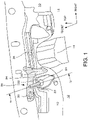
- FIG. 1 shows a schematic structure of a vehicle cabin including a cabin front wall structure of a vehicle.
- a dash panel 10 is a panel member constituting a front wall of the cabin, and is arranged over the entire width of the vehicle cabin in a vehicle width direction.
- the dash panel 10 is composed of a steel material.
- a floor panel 12 extending rearward is placed at a lower end of the dash panel 10.
- a middle region in the vehicle width direction of the vehicle cabin has a floor tunnel 14 which extends from the dash panel 10 toward the rear. The floor tunnel 14 is protruded from the floor panel 12 so as to define a tunnel-shaped space below the floor panel 12.
- a driver seat is located on a left side of the floor tunnel 14, in which a steering column 20 is arranged.
- a portion of the steering column 20 protruded from the dash panel 10 is partially shown.
- An upper end of the steering column 20 is connected to a steering wheel, while a lower end of the steering column 20 is connected to a mechanism for changing an angle of wheels through a steering gear box which houses a rack and pinion and other components. Accordingly, steering of the vehicle is caused when a driver rotates the steering wheel.
- the steering column 20 extends through a column hole 22 defined in the dash panel 10 toward a front compartment (an engine compartment) side.
- the column hole 22 is indicated by a broken leader line.
- a bush 24 composed of an elastic material is inserted into a space between the column hole 22 and the steering column 22.
- a dash cross member 26 which is a reinforcement member extending along a lateral direction of the dash panel 10 is disposed on an upper portion of the dash panel 10. Both upper and lower end portions of the dash cross member 26 are joined to the dash panel 10, and a middle portion of the dash cross member 26 is slightly spaced from a surface of the dash panel 10. In this example, a left end portion of the dash cross member 26 is broadened along a vertical direction, and thus increased in area.
- the dash cross member 26 is typically composed of a steel material.
- a brake bracket 30 is arranged on a diagonally upward left side (a left side in the vehicle width direction) of the column hole 22.
- the brake bracket 30 is attached to the dash panel 10, and a brake pedal is attached to the brake bracket 30.
- An accelerator bracket 32 is arranged on a right side (a right side in the vehicle width direction) of the column hole 22.
- the accelerator bracket 32 is attached to the dash panel 10, and an accelerator pedal is attached to the accelerator bracket 32.
- the brake bracket 30 and the accelerator bracket 32 are placed on opposite sides of the column hole 22 so as to be spaced from each other.
- a brace 34 is provided as a connection member for connecting the brake bracket 30 and the accelerator bracket 32.
- the brake bracket 30, the accelerator bracket 32, and the brace 34 are integrated into one piece so as to constitute, as a whole, a dash brace 36 in the shape of an inverted letter L which is open downward.
- the two brackets can be simultaneously attached only by attaching the dash brace 36 to the dash panel 10, which can facilitate attachment work.
- the brackets and the brace may be formed as separate components which may be joined together by welding or other means.
- the dash brace 36 is typically formed of a steel material.
- the brace 34 which is placed in the vicinity of the upper portion of the dash panel 10 functions as a reinforcement member for reinforcing the dash panel 10.
- the dash cross member 26 is placed under the brace 34 so as to cross the brace 34 in the lateral direction. Because of this, both a part of the dash cross member 26 and the brace 34 can function to reinforce the dash panel 10. It should be noted that the dash cross member 26 may overlap with at least one of the brake bracket 30, the accelerator bracket 32, and the brace 34.
- the brace 34 is arranged so as to extend from an upper left side to a right side of the column hole 22.
- a portion of the dash panel 10 around the column hole 22 is decreased in strength due to the presence of the column hole 22.
- the brace 34 provided close to the column hole 22 can reinforce the decreased strength of the portion of the dash panel 10 located above the column hole 22.
- a rear surface of the brace 34 is generally located at a position slightly spaced from a surface of the dash cross member 26.
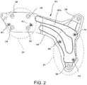
- FIG. 2 shows the structure of an integrated type of the dash brace 36.
- Four attachment holes 38 are defined in the brake bracket 30, and the brake bracket 30 is, on its underside, bolt connected to the dash panel 10 through the attachment hole 38. Further, the brake bracket 30 is, on its front side, joined to a component of the brake pedal.
- a right portion of the brace 34 is extended slightly upward so as to form a region where another attachment hole 38 is defined to enable bolt connection between the dash brace 36 and the dash panel 10.
- a further attachment hold 38 is defined in a lower end portion of the accelerator bracket 32 to enable additional bolt connection between the dash brace 36 and the dash panel 10.
- the brake bracket 30 is provided with two attachment bolts 40, by means of which the component of the brake pedal is fastened to the brake bracket 30.
- the accelerator bracket 32 is equipped with three attachment bolts 40, by means of which the component of the accelerator pedal is fastened to the accelerator bracket 32.
- the dash brace 36 includes a protruded region 36A as appropriate so as to be strengthened compared to a flat plate.
- a protruded region 36A as appropriate so as to be strengthened compared to a flat plate.
- two laterally extending portions of the protruded region 36A are formed on a laterally extending portion of the brace 34, and the remaining other portion of the protruded region 36A is formed so as to surround a portion of the accelerator bracket 32, the accelerator pedal being attached to this portion.
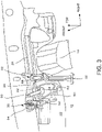
- FIG. 3 shows the schematic structure of the vehicle cabin including the cabin front wall structure of a vehicle as in the case of FIG. 1 , but in a state where a brake pedal 50 and an accelerator pedal 60 are attached to the cabin front wall structure.
- the brake pedal 50 is a component that is stepped on by a driver for braking, and is connected via a connection bar 52 to a brake operating unit 54.
- the brake operating unit 54 transfers an operation amount associated with the brake pedal 50 to a brake controlling mechanism in response to movement of the brake pedal 50 which is stepped on. For example, the brake operating unit 54 transfers, as the operation amount of braking, a change in hydraulic pressure corresponding to an extent to which the brake pedal 50 is stepped on.
- the accelerator pedal 60 is a component stepped on by the driver for acceleration, and is connected via a connection bar 62 to an operation detector 64.
- the operation detector 64 detects an operation amount associated with the accelerator pedal 60 in response to movement of the accelerator pedal 60 which is stepped on, and transfers the detected operation amount to a component for controlling outputs from an engine, a motor and the like. For example, the operation detector 64 transfers, as an output torque command, an electric signal indicative an extent to which the accelerator pedal 60 is stepped on.
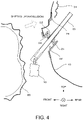
- FIG. 4 shows a cross section view taken along line IV-IV indicated in FIG. 1 .
- the steering column 20 is extended through the inside of the bush 24 housed in the column hole 22, and a tip end of the steering column 20 is connected to a gear box 70. Orientation of wheels is controlled via the gear box 70.
- a part of the dash cross member 26 is located above the column hole 22, while the brace 34 in the dash brace 36 is located at a position rearward (on an inner side in the vehicle cabin) of the dash cross member 26, and partially overlaps with the dash cross member 26.
- a transaxle unit 80 is disposed in a front compartment (engine compartment) located forward of the vehicle cabin. Upon the occurrence of a collision (head-on collision) of the vehicle, the transaxle unit 80 is shifted diagonally rearward (and slightly upward) as indicated by a hollow arrow in FIG. 4 . This may cause a rear wall of the transaxle unit 80 to bump on a portion of the dash panel 10 above the column hole 22. The portion of the dash panel 10 above the column hole 22 has a decreased strength due to the presence of the column hole 22. However, in this embodiment, both the dash cross member 26 and the brace 34 are provided on the portion of the dash panel 10. Because of this, the transaxle unit 80 can be effectively prevented from moving toward a cabin side.
- the dash cross member 26 and the dash brace 36 extend along different directions in such a manner that the dash cross member 26 extends laterally in the vehicle width direction, while the dash brace 36 extends obliquely from upper left to lower right in the vehicle width direction. This can produce an effect such that an intersecting region where the dash cross member 26 and the dash brace 36 overlap with each other is effectively increased in strength.
Landscapes
- Engineering & Computer Science (AREA)
- Chemical & Material Sciences (AREA)
- Combustion & Propulsion (AREA)
- Transportation (AREA)
- Mechanical Engineering (AREA)
- Physics & Mathematics (AREA)
- General Physics & Mathematics (AREA)
- Automation & Control Theory (AREA)
- Body Structure For Vehicles (AREA)
Claims (2)
- Fahrgastraum-Frontwandaufbau eines Fahrzeugs, umfassend:eine Trennwand (10), die eine Frontwand eines Fahrgastraums eines Fahrzeugs darstellt,eine Fahrpedal-Halterung (32), die an der Trennwand (10) angebracht ist und verwendet wird, um ein Fahrpedal zu montieren,eine Bremspedal-Halterung (30), die an der Trennwand (10) an einer von der Fahrpedal-Halterung (32) in einer Fahrzeugbreitenrichtung beabstandeten Position angebracht ist und verwendet wird, um ein Bremspedal zu montieren, undein Verbindungselement (34), das sich entlang einer Oberfläche der Trennwand (10) erstreckt und dazu ausgestaltet ist, die Fahrpedal-Halterung (32) und die Bremspedal-Halterung (30) zu verbinden, dadurch gekennzeichnet, dassdie Trennwand (10) eine Säulenöffnung (22) aufweist, in welche eine Lenksäule (20) eingesetzt ist,die Fahrpedal-Halterung (32) auf einer in der Fahrzeugbreitenrichtung rechten Seite der Säulenöffnung (22) angeordnet ist,die Bremspedal-Halterung (30) auf einer in der Fahrzeugbreitenrichtung linken Seite der Säulenöffnung (22) angeordnet ist, unddas Verbindungselement (34) über der Säulenöffnung (22) angeordnet ist.
- Fahrgastraum-Frontwandaufbau eines Fahrzeugs nach Anspruch 1, ferner umfassend:ein Verstärkungselement (26), das sich entlang der Fahrzeugbreitenrichtung erstreckt und dabei an die Trennwand (10) angepasst ist,wobei das Verstärkungselement (26) so angeordnet ist, dass es mit zumindest einem/einer von dem Verbindungselement (34), der Fahrpedal-Halterung (32) und der Bremspedal-Halterung (30) überlappt.
Applications Claiming Priority (1)
| Application Number | Priority Date | Filing Date | Title |
|---|---|---|---|
| JP2018139509A JP7056438B2 (ja) | 2018-07-25 | 2018-07-25 | 車室前壁部構造 |
Publications (2)
| Publication Number | Publication Date |
|---|---|
| EP3599530A1 EP3599530A1 (de) | 2020-01-29 |
| EP3599530B1 true EP3599530B1 (de) | 2022-04-27 |
Family
ID=67438940
Family Applications (1)
| Application Number | Title | Priority Date | Filing Date |
|---|---|---|---|
| EP19188432.9A Active EP3599530B1 (de) | 2018-07-25 | 2019-07-25 | Kabinenfrontwandstruktur eines fahrzeugs |
Country Status (4)
| Country | Link |
|---|---|
| US (1) | US11142258B2 (de) |
| EP (1) | EP3599530B1 (de) |
| JP (1) | JP7056438B2 (de) |
| CN (1) | CN110775166B (de) |
Family Cites Families (27)
| Publication number | Priority date | Publication date | Assignee | Title |
|---|---|---|---|---|
| IT1224026B (it) * | 1988-12-23 | 1990-09-26 | Fiat Auto Spa | Struttura di veicolo e metodo per il suo assemblaggio |
| GB8926700D0 (en) * | 1989-11-25 | 1990-01-17 | Sterling Engineered Products L | Improvements relating to motor vehicles control pedals and their mountings |
| JPH06206230A (ja) * | 1993-01-11 | 1994-07-26 | Ikeda Bussan Co Ltd | ダッシュパネルパッドおよびその製造方法 |
| IT1267210B1 (it) * | 1994-12-29 | 1997-01-28 | Ersi Italia Spa | Gruppo di pedaliera per un autoveicolo. |
| JPH1120491A (ja) * | 1997-07-03 | 1999-01-26 | Araco Corp | アクセルペダルストッパ構造 |
| DE19845012A1 (de) * | 1998-09-30 | 2000-04-06 | Volkswagen Ag | Montageteil als Teil der Spritzwand eines Kraftfahrzeugs |
| JP3652158B2 (ja) * | 1999-02-19 | 2005-05-25 | ダイハツ工業株式会社 | アクセルペダル取付構造 |
| JP2003223233A (ja) * | 2002-01-29 | 2003-08-08 | Daihatsu Motor Co Ltd | 自動車 |
| JP2003312543A (ja) * | 2002-04-19 | 2003-11-06 | Suzuki Motor Corp | ステアリングサポートメンバの取付構造 |
| CN2555185Y (zh) * | 2002-07-18 | 2003-06-11 | 中国重型汽车集团有限公司 | 汽车用组合踏板 |
| JP4191476B2 (ja) | 2002-12-27 | 2008-12-03 | 株式会社エフテック | 車両のペダル前後位置調節装置 |
| DE10323999B4 (de) * | 2003-05-27 | 2005-09-22 | Dr.Ing.H.C. F. Porsche Ag | Befestigungsanordnung für ein Cockpitmodul eines Kraftfahrzeuges |
| JP4029808B2 (ja) * | 2003-09-03 | 2008-01-09 | マツダ株式会社 | 自動車のペダル支持構造 |
| JP4470665B2 (ja) | 2004-09-14 | 2010-06-02 | マツダ株式会社 | 車両のダッシュパネル構造 |
| JP4887509B2 (ja) * | 2005-08-11 | 2012-02-29 | アイ・アール・ケア株式会社 | 自動車の運転補助装置 |
| JP4939288B2 (ja) * | 2007-04-16 | 2012-05-23 | 株式会社エフテック | 車両用調節式ペダル装置 |
| CN201665162U (zh) * | 2009-12-25 | 2010-12-08 | 上海汽车集团股份有限公司 | 一种汽车踏板连接板结构 |
| JP5268954B2 (ja) * | 2010-01-07 | 2013-08-21 | 豊田鉄工株式会社 | 車両用操作ペダル装置 |
| FR2960202B1 (fr) * | 2010-05-18 | 2013-06-14 | Peugeot Citroen Automobiles Sa | Agencement pour le montage d'elements d'un systeme de commande de frein principal d'un vehicule, et vehicule comportant un tel agencement |
| EP2559611B1 (de) * | 2010-06-24 | 2014-02-19 | Honda Motor Co., Ltd. | Struktur für den vorderteil einer fahrzeugkarosserie |
| BRPI1103621A2 (pt) * | 2010-07-02 | 2012-11-20 | Honda Motor Co Ltd | estrutura frontal de veÍculo |
| JP4918153B2 (ja) | 2010-07-02 | 2012-04-18 | 本田技研工業株式会社 | 車体前部構造 |
| CN202765104U (zh) * | 2012-08-29 | 2013-03-06 | 力帆实业(集团)股份有限公司 | 左右舵汽车前围板 |
| CN202863573U (zh) * | 2012-09-26 | 2013-04-10 | 浙江吉利汽车研究院有限公司杭州分公司 | 一种左右置车的前围板 |
| JP6522982B2 (ja) * | 2015-02-18 | 2019-05-29 | 本田技研工業株式会社 | 車体構造 |
| JP6624489B2 (ja) * | 2015-07-17 | 2019-12-25 | スズキ株式会社 | ステアリングサポートメンバー |
| JP7095476B2 (ja) * | 2018-08-07 | 2022-07-05 | トヨタ自動車株式会社 | 車両前部構造 |
-
2018
- 2018-07-25 JP JP2018139509A patent/JP7056438B2/ja active Active
-
2019
- 2019-07-22 CN CN201910662338.6A patent/CN110775166B/zh active Active
- 2019-07-23 US US16/519,524 patent/US11142258B2/en active Active
- 2019-07-25 EP EP19188432.9A patent/EP3599530B1/de active Active
Also Published As
| Publication number | Publication date |
|---|---|
| EP3599530A1 (de) | 2020-01-29 |
| JP7056438B2 (ja) | 2022-04-19 |
| CN110775166B (zh) | 2022-02-08 |
| US11142258B2 (en) | 2021-10-12 |
| CN110775166A (zh) | 2020-02-11 |
| JP2020015413A (ja) | 2020-01-30 |
| US20200031402A1 (en) | 2020-01-30 |
Similar Documents
| Publication | Publication Date | Title |
|---|---|---|
| US10000239B2 (en) | Automobile vehicle body structure | |
| EP1183177B1 (de) | Armaturenbrett mit symmetrischem unterbau | |
| JP2001225766A (ja) | 自動車の車体構造 | |
| JPS6116131A (ja) | 自動車の後部領域の燃料タンク装置 | |
| JP2004017698A (ja) | ペダル後退量抑制装置 | |
| US10457332B1 (en) | Structure of a front part of the bodyshell of a vehicle, notably a motor vehicle | |
| EP1767420B1 (de) | Einbruchssicheres Pedalsystem | |
| EP3599530B1 (de) | Kabinenfrontwandstruktur eines fahrzeugs | |
| JP3311665B2 (ja) | 自動車の車体トンネル補強構造 | |
| JP7243438B2 (ja) | 車両前部構造 | |
| JP2003312542A (ja) | 車体前部構造 | |
| JPS62113653A (ja) | 自動車のカウル構造 | |
| JP2528272Y2 (ja) | インストルメントパネルのフレーム取付構造 | |
| JP4485993B2 (ja) | ステアリングハンガビームの取付部構造 | |
| JP4581621B2 (ja) | 車両の燃料タンク支持構造 | |
| JP4470665B2 (ja) | 車両のダッシュパネル構造 | |
| JPH1159182A (ja) | 車体構造 | |
| JP3969086B2 (ja) | キャブオーバー型車のキャブフロア構造 | |
| JPH0627443U (ja) | 後部車体構造 | |
| JP3668060B2 (ja) | 自動車の前部車体構造 | |
| KR100622497B1 (ko) | 조향 칼럼의 하부 장착구조 | |
| WO2016208064A1 (ja) | 車体前部構造 | |
| JP2024134323A (ja) | 車両構造 | |
| JP5955704B2 (ja) | 車両の前端部構造 | |
| JP2006199082A (ja) | 車体前部構造 |
Legal Events
| Date | Code | Title | Description |
|---|---|---|---|
| PUAI | Public reference made under article 153(3) epc to a published international application that has entered the european phase |
Free format text: ORIGINAL CODE: 0009012 |
|
| STAA | Information on the status of an ep patent application or granted ep patent |
Free format text: STATUS: REQUEST FOR EXAMINATION WAS MADE |
|
| 17P | Request for examination filed |
Effective date: 20190725 |
|
| AK | Designated contracting states |
Kind code of ref document: A1 Designated state(s): AL AT BE BG CH CY CZ DE DK EE ES FI FR GB GR HR HU IE IS IT LI LT LU LV MC MK MT NL NO PL PT RO RS SE SI SK SM TR |
|
| AX | Request for extension of the european patent |
Extension state: BA ME |
|
| GRAP | Despatch of communication of intention to grant a patent |
Free format text: ORIGINAL CODE: EPIDOSNIGR1 |
|
| STAA | Information on the status of an ep patent application or granted ep patent |
Free format text: STATUS: GRANT OF PATENT IS INTENDED |
|
| INTG | Intention to grant announced |
Effective date: 20211123 |
|
| GRAS | Grant fee paid |
Free format text: ORIGINAL CODE: EPIDOSNIGR3 |
|
| GRAA | (expected) grant |
Free format text: ORIGINAL CODE: 0009210 |
|
| STAA | Information on the status of an ep patent application or granted ep patent |
Free format text: STATUS: THE PATENT HAS BEEN GRANTED |
|
| AK | Designated contracting states |
Kind code of ref document: B1 Designated state(s): AL AT BE BG CH CY CZ DE DK EE ES FI FR GB GR HR HU IE IS IT LI LT LU LV MC MK MT NL NO PL PT RO RS SE SI SK SM TR |
|
| REG | Reference to a national code |
Ref country code: GB Ref legal event code: FG4D |
|
| REG | Reference to a national code |
Ref country code: CH Ref legal event code: EP |
|
| REG | Reference to a national code |
Ref country code: DE Ref legal event code: R096 Ref document number: 602019014059 Country of ref document: DE |
|
| REG | Reference to a national code |
Ref country code: AT Ref legal event code: REF Ref document number: 1487439 Country of ref document: AT Kind code of ref document: T Effective date: 20220515 |
|
| REG | Reference to a national code |
Ref country code: IE Ref legal event code: FG4D |
|
| REG | Reference to a national code |
Ref country code: LT Ref legal event code: MG9D |
|
| REG | Reference to a national code |
Ref country code: NL Ref legal event code: MP Effective date: 20220427 |
|
| REG | Reference to a national code |
Ref country code: AT Ref legal event code: MK05 Ref document number: 1487439 Country of ref document: AT Kind code of ref document: T Effective date: 20220427 |
|
| PG25 | Lapsed in a contracting state [announced via postgrant information from national office to epo] |
Ref country code: NL Free format text: LAPSE BECAUSE OF FAILURE TO SUBMIT A TRANSLATION OF THE DESCRIPTION OR TO PAY THE FEE WITHIN THE PRESCRIBED TIME-LIMIT Effective date: 20220427 |
|
| PG25 | Lapsed in a contracting state [announced via postgrant information from national office to epo] |
Ref country code: SE Free format text: LAPSE BECAUSE OF FAILURE TO SUBMIT A TRANSLATION OF THE DESCRIPTION OR TO PAY THE FEE WITHIN THE PRESCRIBED TIME-LIMIT Effective date: 20220427 Ref country code: PT Free format text: LAPSE BECAUSE OF FAILURE TO SUBMIT A TRANSLATION OF THE DESCRIPTION OR TO PAY THE FEE WITHIN THE PRESCRIBED TIME-LIMIT Effective date: 20220829 Ref country code: NO Free format text: LAPSE BECAUSE OF FAILURE TO SUBMIT A TRANSLATION OF THE DESCRIPTION OR TO PAY THE FEE WITHIN THE PRESCRIBED TIME-LIMIT Effective date: 20220727 Ref country code: LT Free format text: LAPSE BECAUSE OF FAILURE TO SUBMIT A TRANSLATION OF THE DESCRIPTION OR TO PAY THE FEE WITHIN THE PRESCRIBED TIME-LIMIT Effective date: 20220427 Ref country code: HR Free format text: LAPSE BECAUSE OF FAILURE TO SUBMIT A TRANSLATION OF THE DESCRIPTION OR TO PAY THE FEE WITHIN THE PRESCRIBED TIME-LIMIT Effective date: 20220427 Ref country code: GR Free format text: LAPSE BECAUSE OF FAILURE TO SUBMIT A TRANSLATION OF THE DESCRIPTION OR TO PAY THE FEE WITHIN THE PRESCRIBED TIME-LIMIT Effective date: 20220728 Ref country code: FI Free format text: LAPSE BECAUSE OF FAILURE TO SUBMIT A TRANSLATION OF THE DESCRIPTION OR TO PAY THE FEE WITHIN THE PRESCRIBED TIME-LIMIT Effective date: 20220427 Ref country code: ES Free format text: LAPSE BECAUSE OF FAILURE TO SUBMIT A TRANSLATION OF THE DESCRIPTION OR TO PAY THE FEE WITHIN THE PRESCRIBED TIME-LIMIT Effective date: 20220427 Ref country code: BG Free format text: LAPSE BECAUSE OF FAILURE TO SUBMIT A TRANSLATION OF THE DESCRIPTION OR TO PAY THE FEE WITHIN THE PRESCRIBED TIME-LIMIT Effective date: 20220727 Ref country code: AT Free format text: LAPSE BECAUSE OF FAILURE TO SUBMIT A TRANSLATION OF THE DESCRIPTION OR TO PAY THE FEE WITHIN THE PRESCRIBED TIME-LIMIT Effective date: 20220427 |
|
| PG25 | Lapsed in a contracting state [announced via postgrant information from national office to epo] |
Ref country code: RS Free format text: LAPSE BECAUSE OF FAILURE TO SUBMIT A TRANSLATION OF THE DESCRIPTION OR TO PAY THE FEE WITHIN THE PRESCRIBED TIME-LIMIT Effective date: 20220427 Ref country code: PL Free format text: LAPSE BECAUSE OF FAILURE TO SUBMIT A TRANSLATION OF THE DESCRIPTION OR TO PAY THE FEE WITHIN THE PRESCRIBED TIME-LIMIT Effective date: 20220427 Ref country code: LV Free format text: LAPSE BECAUSE OF FAILURE TO SUBMIT A TRANSLATION OF THE DESCRIPTION OR TO PAY THE FEE WITHIN THE PRESCRIBED TIME-LIMIT Effective date: 20220427 Ref country code: IS Free format text: LAPSE BECAUSE OF FAILURE TO SUBMIT A TRANSLATION OF THE DESCRIPTION OR TO PAY THE FEE WITHIN THE PRESCRIBED TIME-LIMIT Effective date: 20220827 |
|
| REG | Reference to a national code |
Ref country code: DE Ref legal event code: R097 Ref document number: 602019014059 Country of ref document: DE |
|
| PG25 | Lapsed in a contracting state [announced via postgrant information from national office to epo] |
Ref country code: SM Free format text: LAPSE BECAUSE OF FAILURE TO SUBMIT A TRANSLATION OF THE DESCRIPTION OR TO PAY THE FEE WITHIN THE PRESCRIBED TIME-LIMIT Effective date: 20220427 Ref country code: SK Free format text: LAPSE BECAUSE OF FAILURE TO SUBMIT A TRANSLATION OF THE DESCRIPTION OR TO PAY THE FEE WITHIN THE PRESCRIBED TIME-LIMIT Effective date: 20220427 Ref country code: RO Free format text: LAPSE BECAUSE OF FAILURE TO SUBMIT A TRANSLATION OF THE DESCRIPTION OR TO PAY THE FEE WITHIN THE PRESCRIBED TIME-LIMIT Effective date: 20220427 Ref country code: EE Free format text: LAPSE BECAUSE OF FAILURE TO SUBMIT A TRANSLATION OF THE DESCRIPTION OR TO PAY THE FEE WITHIN THE PRESCRIBED TIME-LIMIT Effective date: 20220427 Ref country code: DK Free format text: LAPSE BECAUSE OF FAILURE TO SUBMIT A TRANSLATION OF THE DESCRIPTION OR TO PAY THE FEE WITHIN THE PRESCRIBED TIME-LIMIT Effective date: 20220427 Ref country code: CZ Free format text: LAPSE BECAUSE OF FAILURE TO SUBMIT A TRANSLATION OF THE DESCRIPTION OR TO PAY THE FEE WITHIN THE PRESCRIBED TIME-LIMIT Effective date: 20220427 |
|
| PG25 | Lapsed in a contracting state [announced via postgrant information from national office to epo] |
Ref country code: MC Free format text: LAPSE BECAUSE OF FAILURE TO SUBMIT A TRANSLATION OF THE DESCRIPTION OR TO PAY THE FEE WITHIN THE PRESCRIBED TIME-LIMIT Effective date: 20220427 |
|
| REG | Reference to a national code |
Ref country code: CH Ref legal event code: PL |
|
| PLBE | No opposition filed within time limit |
Free format text: ORIGINAL CODE: 0009261 |
|
| STAA | Information on the status of an ep patent application or granted ep patent |
Free format text: STATUS: NO OPPOSITION FILED WITHIN TIME LIMIT |
|
| REG | Reference to a national code |
Ref country code: BE Ref legal event code: MM Effective date: 20220731 |
|
| PG25 | Lapsed in a contracting state [announced via postgrant information from national office to epo] |
Ref country code: AL Free format text: LAPSE BECAUSE OF FAILURE TO SUBMIT A TRANSLATION OF THE DESCRIPTION OR TO PAY THE FEE WITHIN THE PRESCRIBED TIME-LIMIT Effective date: 20220427 |
|
| 26N | No opposition filed |
Effective date: 20230130 |
|
| PG25 | Lapsed in a contracting state [announced via postgrant information from national office to epo] |
Ref country code: LU Free format text: LAPSE BECAUSE OF NON-PAYMENT OF DUE FEES Effective date: 20220725 Ref country code: LI Free format text: LAPSE BECAUSE OF NON-PAYMENT OF DUE FEES Effective date: 20220731 Ref country code: FR Free format text: LAPSE BECAUSE OF NON-PAYMENT OF DUE FEES Effective date: 20220731 Ref country code: CH Free format text: LAPSE BECAUSE OF NON-PAYMENT OF DUE FEES Effective date: 20220731 |
|
| PG25 | Lapsed in a contracting state [announced via postgrant information from national office to epo] |
Ref country code: SI Free format text: LAPSE BECAUSE OF FAILURE TO SUBMIT A TRANSLATION OF THE DESCRIPTION OR TO PAY THE FEE WITHIN THE PRESCRIBED TIME-LIMIT Effective date: 20220427 Ref country code: BE Free format text: LAPSE BECAUSE OF NON-PAYMENT OF DUE FEES Effective date: 20220731 |
|
| P01 | Opt-out of the competence of the unified patent court (upc) registered |
Effective date: 20230427 |
|
| REG | Reference to a national code |
Ref country code: DE Ref legal event code: R084 Ref document number: 602019014059 Country of ref document: DE |
|
| PG25 | Lapsed in a contracting state [announced via postgrant information from national office to epo] |
Ref country code: IE Free format text: LAPSE BECAUSE OF NON-PAYMENT OF DUE FEES Effective date: 20220725 |
|
| PG25 | Lapsed in a contracting state [announced via postgrant information from national office to epo] |
Ref country code: IT Free format text: LAPSE BECAUSE OF FAILURE TO SUBMIT A TRANSLATION OF THE DESCRIPTION OR TO PAY THE FEE WITHIN THE PRESCRIBED TIME-LIMIT Effective date: 20220427 |
|
| GBPC | Gb: european patent ceased through non-payment of renewal fee |
Effective date: 20230725 |
|
| PG25 | Lapsed in a contracting state [announced via postgrant information from national office to epo] |
Ref country code: HU Free format text: LAPSE BECAUSE OF FAILURE TO SUBMIT A TRANSLATION OF THE DESCRIPTION OR TO PAY THE FEE WITHIN THE PRESCRIBED TIME-LIMIT; INVALID AB INITIO Effective date: 20190725 |
|
| PG25 | Lapsed in a contracting state [announced via postgrant information from national office to epo] |
Ref country code: MK Free format text: LAPSE BECAUSE OF FAILURE TO SUBMIT A TRANSLATION OF THE DESCRIPTION OR TO PAY THE FEE WITHIN THE PRESCRIBED TIME-LIMIT Effective date: 20220427 Ref country code: CY Free format text: LAPSE BECAUSE OF FAILURE TO SUBMIT A TRANSLATION OF THE DESCRIPTION OR TO PAY THE FEE WITHIN THE PRESCRIBED TIME-LIMIT Effective date: 20220427 Ref country code: GB Free format text: LAPSE BECAUSE OF NON-PAYMENT OF DUE FEES Effective date: 20230725 |
|
| PG25 | Lapsed in a contracting state [announced via postgrant information from national office to epo] |
Ref country code: MT Free format text: LAPSE BECAUSE OF FAILURE TO SUBMIT A TRANSLATION OF THE DESCRIPTION OR TO PAY THE FEE WITHIN THE PRESCRIBED TIME-LIMIT Effective date: 20220427 |
|
| PG25 | Lapsed in a contracting state [announced via postgrant information from national office to epo] |
Ref country code: BG Free format text: LAPSE BECAUSE OF FAILURE TO SUBMIT A TRANSLATION OF THE DESCRIPTION OR TO PAY THE FEE WITHIN THE PRESCRIBED TIME-LIMIT Effective date: 20220427 |
|
| PG25 | Lapsed in a contracting state [announced via postgrant information from national office to epo] |
Ref country code: BG Free format text: LAPSE BECAUSE OF FAILURE TO SUBMIT A TRANSLATION OF THE DESCRIPTION OR TO PAY THE FEE WITHIN THE PRESCRIBED TIME-LIMIT Effective date: 20220427 |
|
| PGFP | Annual fee paid to national office [announced via postgrant information from national office to epo] |
Ref country code: DE Payment date: 20250528 Year of fee payment: 7 |
|
| PG25 | Lapsed in a contracting state [announced via postgrant information from national office to epo] |
Ref country code: TR Free format text: LAPSE BECAUSE OF FAILURE TO SUBMIT A TRANSLATION OF THE DESCRIPTION OR TO PAY THE FEE WITHIN THE PRESCRIBED TIME-LIMIT Effective date: 20220427 |