EP3585929B1 - Flechtmaschine - Google Patents
Flechtmaschine Download PDFInfo
- Publication number
- EP3585929B1 EP3585929B1 EP18706719.4A EP18706719A EP3585929B1 EP 3585929 B1 EP3585929 B1 EP 3585929B1 EP 18706719 A EP18706719 A EP 18706719A EP 3585929 B1 EP3585929 B1 EP 3585929B1
- Authority
- EP
- European Patent Office
- Prior art keywords
- braiding
- speed
- machine
- braiding machine
- designed
- Prior art date
- Legal status (The legal status is an assumption and is not a legal conclusion. Google has not performed a legal analysis and makes no representation as to the accuracy of the status listed.)
- Active
Links
Images


Classifications
-
- D—TEXTILES; PAPER
- D04—BRAIDING; LACE-MAKING; KNITTING; TRIMMINGS; NON-WOVEN FABRICS
- D04C—BRAIDING OR MANUFACTURE OF LACE, INCLUDING BOBBIN-NET OR CARBONISED LACE; BRAIDING MACHINES; BRAID; LACE
- D04C3/00—Braiding or lacing machines
- D04C3/40—Braiding or lacing machines for making tubular braids by circulating strand supplies around braiding centre at equal distances
-
- D—TEXTILES; PAPER
- D04—BRAIDING; LACE-MAKING; KNITTING; TRIMMINGS; NON-WOVEN FABRICS
- D04C—BRAIDING OR MANUFACTURE OF LACE, INCLUDING BOBBIN-NET OR CARBONISED LACE; BRAIDING MACHINES; BRAID; LACE
- D04C3/00—Braiding or lacing machines
- D04C3/02—Braiding or lacing machines with spool carriers guided by track plates or by bobbin heads exclusively
- D04C3/38—Driving-gear; Starting or stopping mechanisms
-
- D—TEXTILES; PAPER
- D04—BRAIDING; LACE-MAKING; KNITTING; TRIMMINGS; NON-WOVEN FABRICS
- D04C—BRAIDING OR MANUFACTURE OF LACE, INCLUDING BOBBIN-NET OR CARBONISED LACE; BRAIDING MACHINES; BRAID; LACE
- D04C3/00—Braiding or lacing machines
- D04C3/02—Braiding or lacing machines with spool carriers guided by track plates or by bobbin heads exclusively
- D04C3/14—Spool carriers
-
- D—TEXTILES; PAPER
- D04—BRAIDING; LACE-MAKING; KNITTING; TRIMMINGS; NON-WOVEN FABRICS
- D04C—BRAIDING OR MANUFACTURE OF LACE, INCLUDING BOBBIN-NET OR CARBONISED LACE; BRAIDING MACHINES; BRAID; LACE
- D04C3/00—Braiding or lacing machines
- D04C3/40—Braiding or lacing machines for making tubular braids by circulating strand supplies around braiding centre at equal distances
- D04C3/42—Braiding or lacing machines for making tubular braids by circulating strand supplies around braiding centre at equal distances with means for forming sheds by controlling guides for individual threads
-
- D—TEXTILES; PAPER
- D04—BRAIDING; LACE-MAKING; KNITTING; TRIMMINGS; NON-WOVEN FABRICS
- D04C—BRAIDING OR MANUFACTURE OF LACE, INCLUDING BOBBIN-NET OR CARBONISED LACE; BRAIDING MACHINES; BRAID; LACE
- D04C3/00—Braiding or lacing machines
- D04C3/48—Auxiliary devices
Definitions
- the present invention relates to a braiding machine and a method for controlling such a braiding machine.
- Braiding machines for braiding a piece of braided material are known in the prior art. Braiding machines are currently operated at a constant speed which must not exceed a maximum speed. The maximum permissible speed is significantly limited by the maximum permissible load on the machine, which in turn is a result of the maximum permissible centrifugal force.
- the braiding machine has a first set of bobbins and at least one second set of bobbins, which move relative to one another during braiding, at least one of the sets of bobbins being guided along a circular guide path.
- a first aspect of the present invention relates to a braiding machine.
- the braiding machine has several braided material carriers, a drive and a control device.
- the braided material carriers are arranged around a common braiding center of the braiding machine.
- the braided material carriers are each designed to carry a woven material to be braided in the common braiding center.
- the drive is designed to drive the multiple braided material carriers in such a way that they move around the common braiding center.
- the control device is designed to control the drive in such a way that a centrifugal force acting on at least one of the braided material carriers remains at least almost constant.
- the braiding machine has at least one unbalance sensor which is designed to determine an unbalance of the multiple braided material carriers when rotating around the common braiding center, and the control device is designed to take the determined unbalance into account when controlling the drive.
- the drive is designed to drive the multiple braided material carriers in such a way that they rotate about the common braiding center / that they rotate about the common braiding center.
- a second aspect of the invention relates to a method of controlling a braiding machine.
- the braiding machine has several braided material carriers, a drive, a control device and at least one unbalance sensor.
- the multiple braided material carriers are arranged around a common braiding center of the braiding machine.
- the braided material carriers are each designed to carry a woven material to be braided in the common braiding center.
- the method describes driving the plurality of braided material carriers in such a way that they move around the common braiding center.
- the method also describes controlling the drive in such a way that a centrifugal force acting on at least one of the braided material carriers remains at least almost constant.
- the method describes the determination of an imbalance of the plurality of braided material carriers during rotation about the common braiding center by the at least one unbalance sensor and the consideration of the determined unbalance by the control device when controlling the drive.
- the multiple braided material carriers are driven in such a way that they rotate around the common braiding center / that they rotate around the common braiding center.
- the drive is controlled by the control device in such a way that a centrifugal force acting on at least one of the braided material carriers remains at least almost constant / is kept constant.
- braided material carried by the braided material carriers is braided continuously. Therefore, the filling level of the filling carriers and thus the mass of the braided material carriers change during a braiding process.
- no constant speed is set but an at least almost constant centrifugal force is maintained.
- the speed does not have to be kept constant but can be increased, for example, if the mass of the at least one braided material carrier decreases as long as the centrifugal force acting on this remains at least almost constant. With decreasing mass, an increase in the rotational speed leads to an at least almost constant centrifugal force acting on the at least one woven material carrier.
- An increase in the speed leads to an increase in productivity.
- the braided material carriers run in a circle around the common braiding center, i.e. they are arranged along a circumference around the common braiding center.
- the braided goods can be arranged in the circumferential direction around the common braiding center at a constant distance from one another.
- the braided material carriers can be spools on which the woven material can be rolled up, for example.
- the braided material carriers are arranged in the radial direction at the same distance from the braiding center.
- the radial distance between the braided material carriers and the braiding center can be constant / unchangeable or changeable.
- the braided material carriers can be provided with the same or at least partially different amount of braided material.
- the braided material provided by the braided material carriers is braided with one another.
- the braiding center can also be referred to as the braiding axis of the braiding machine.
- the braiding center can be parallel to or correspond to the longitudinal axis of the braiding machine.
- the braided material carriers are applied or arranged on a common carrier.
- the common carrier By moving, for example rotating, the common carrier, the described movement of the braided material carriers can be carried out around the common braiding center.
- an immovable braided material carrier can be provided, so that the woven material provided by the multiple woven material carriers and the woven material provided by the immovable woven material carrier are interwoven in a known manner.
- the aspects and details described herein relate to the movement of the braided material carriers applied or arranged, for example, on the common carrier.
- the plurality of braided material carriers are applied or arranged on a first common carrier and further woven material carriers are applied or arranged on a second common carrier.
- the two Common carriers can be designed in a specific embodiment as sets of coils or rings.
- the two carriers can each be driven by a common drive or by separate / different drives.
- a braiding process can be carried out in a known manner, for example by moving the two common carriers in opposite directions, for example rotating them in opposite directions.
- the aspects and details described herein can relate to the movement of the braided material carriers applied or arranged, for example, on the first common carrier.
- aspects and details described herein can relate to the movement of the braided material carriers applied or arranged, for example, on the second common carrier.
- a so-called lower rim on the outside which is provided with braided material carriers, can move in opposite directions to an inner, so-called upper rim, which is also provided with braided material carriers.
- the aspects and details described herein may relate to the lower rim and / or the upper rim of the braiding machine.
- the braided material can be any conceivable strand-like or elongated material that is suitable for a braiding process. With the help of the braiding machine, various braids can therefore be produced from strand-like material such as wires or textile fibers, for example in the form of tubular braids or braids and / or for braiding around a cable, for example, with a wire braid.
- the braiding machine can be, for example, a wire braiding machine that is especially suitable for braiding wires.
- the braiding machine can be a rotary braiding machine.
- a braiding process can be understood as a complete process for manufacturing a braided product. Furthermore, it is conceivable that a braiding process can be understood to mean a process that lasts from starting the braiding machine to stopping the braiding machine. The braiding machine is stopped, for example, when one or more of the braided material carriers have run empty and are each replaced by a full one, i.e. fully filled with braided material.
- control device During a braiding process, the drive is controlled by the control device in such a way that the centrifugal force acting on all of the braided material carriers remains at least almost constant.
- controlling can be understood here to include controlling and / or regulating.
- the filling level of the filling carriers and thus the mass of the braided material carriers change during a braiding process.
- the degree of filling and thus the mass of the braided material can be the same. If, in this case, the centrifugal force acting on one of the braided material carriers is kept constant, the centrifugal force acting on the other woven material carriers is automatically kept constant at the same value.
- the drive can be designed to drive the multiple braided material carriers in such a way that they rotate around the common braiding center at an adjustable speed.
- the control device can be designed to adapt the adaptable speed in such a way that the centrifugal force acting on the at least one of the braided material carriers remains at least almost constant.
- the control device can be designed to adapt the adaptable speed in such a way that the centrifugal force acting on all braided material carriers remains at least almost constant.
- the control device can be designed to control the drive of the braiding machine in such a way that the plurality of braided material carriers rotate around the common braiding center at the adapted speed.
- the drive can receive appropriate control instructions from the control device.
- the drive can drive the braided material carriers accordingly based on the control instructions.
- the drive can be designed to drive the multiple braided material carriers in such a way that they rotate around the common braiding center at an adjustable angular speed or speed.
- the control device can be designed to adapt the adjustable angular speed or speed in such a way that the centrifugal force acting on the at least one of the braided material carriers remains at least almost constant.
- the control device can be designed to adapt the adjustable angular speed or speed in such a way that the centrifugal force acting on all of the braided material carriers remains at least almost constant.
- the centrifugal force acting on it is kept at least almost constant by adapting the rotational speed, angular speed or speed.
- braided material provided by the braided material carriers is braided. Therefore, the filling level of the filling carriers and thus the mass of the braided material carriers change during a braiding process.
- the rotational speed, angular speed or speed is not set and kept constant, but can be increased, for example, if the mass of the at least one braided material carrier decreases, as long as the centrifugal force acting on the at least one woven material carrier remains at least almost constant.
- An increase in the rotational speed, angular velocity or speed leads to an increase in productivity.
- the control device can be designed to adjust the adjustable speed several times / repeatedly during a braiding process.
- the adjustable speed can be adjusted in fixed or variable time intervals during a braiding process. Purely by way of example, it should be mentioned here that the adjustable speed is continuously / continuously adjusted during a braiding process.
- the drive can be controlled even more precisely through the repeated, for example continuous, adjustment of the speed. Since the centrifugal force is a quadratic function of the speed, the maximum permissible machine speed increases with constant centrifugal force and steadily decreasing mass. This allows the speed to be increased in order to increase productivity.
- the multiple adjustment of the speed ensures that the speed can be increased several times during a braiding process. This increases the productivity increase during the braiding process.
- the control device can be designed to control the drive in such a way that a maximum centrifugal force acting on at least one of the braided material carriers remains at least almost constant.
- the control device can be designed to adapt the adaptable speed in such a way that a maximum centrifugal force acting on at least one of the braided material carriers remains at least almost constant.
- the braiding machine is designed for the maximum effective centrifugal force. This ensures more reliable protection against overloading the braiding machine.
- the control device can be designed to control the drive as a function of the mass of at least one of the braided material carriers.
- the control device can be designed to adapt the adaptable speed as a function of the mass of at least one of the braided material carriers.
- the mass of at least one of the braided material carriers is taken into account when controlling the drive, e.g. when adjusting the speed.
- braided material provided by the braided material carriers is braided. Therefore, the filling level of the filling carriers and thus the mass of the braided material carriers change during a braiding process.
- the rotational speed can be adapted in accordance with the changed mass in order to keep the centrifugal force acting on the at least one woven material carrier constant.
- the mass of all braided material carriers is determined, for example.
- a mean or median value can be formed from the determined masses. The determined mean or median value of the masses can then be taken into account when adjusting the speed.
- the control device can be designed to control the drive as a function of the mass of the braided material carrier with the greatest mass of the plurality of woven material carriers.
- the control device can be designed to adapt the adaptable speed as a function of the mass of the braided material carrier with the greatest mass of the plurality of woven material carriers.
- the control device can determine the mass of all braided material carriers and, by comparison, the mass of the woven material carrier with the largest mass and take it into account for controlling the braiding machine, e.g. for adapting the adjustable speed.
- the adjustable speed can be selected in such a way that a maximum permissible centrifugal force of the braiding machine is not exceeded.
- the mass of the braided material can be viewed as a quadratic function of a circular ring area.
- the circular area can be the path on which the braided material carriers move around the braiding center. If the speed is regulated after the braided material carrier with the highest mass, the mass of the remaining bobbins decreases correspondingly faster. In the case of at least partially different degrees of filling of the braided material carriers, the mass of the other braided article carriers with a lower degree of filling therefore does not remain constant.
- control / regulation after the braided material carrier with the highest mass provides an accurate and simple possibility of maintaining the centrifugal force and, with decreasing mass, increasing the speed.
- the degree of filling and thus the mass of at least some of the braided material carriers of the braiding machine can differ.
- the braiding machine is designed for the maximum effective centrifugal force. This ensures more reliable protection against overloading the braiding machine.
- the adjustable speed can be determined from the maximum filled braided material carrier.
- the constant centrifugal force can be below the maximum permissible centrifugal force or be selected in such a way, i.e. below the centrifugal force that is present in known braiding machines with constant speed. This not only increases productivity over the life of the machine, but also reduces the maximum machine load.
- the control / regulation of the braiding machine can be linear, for example.
- the braiding process can be started at a speed which, for example, corresponds at least almost to the permissible actual speed of the braiding machine.
- the braiding machine can be controlled / regulated in such a way that it runs at a speed that increases linearly, for example, until a maximum speed, for example a maximum speed permissible with a defined filling of the at least one braided material carrier, is reached.
- the braiding machine can start at an output speed and, for example, at a degree of filling of 60% of the at least one braided material carrier reach a maximum speed after a certain time. This can be regulated by means of a sensor or unregulated with a fixed setting.
- the mass of the braided material can be determined in various ways.
- the control device can estimate the mass of the at least one braided article carrier based on operating parameters of the braiding machine and / or information about the at least one braided article carrier. For example, the control device can take into account at what point in time the braided material carrier was attached to the braiding machine in a full state, at what speed the braiding machine has been running since this point in time and what initial mass the braided material carrier had in a full state. The current mass of the braided material can be derived from these or similar parameters. In this way, the mass of the at least one braided material carrier can be estimated without further components.
- the braiding machine can have at least one sensor.
- the sensor can be designed to detect the degree of filling of at least one of the braided material carriers with braided material.
- a braiding machine with a first common carrier of braided carriers and a second common carrier of braided carriers, for example an outer lower rim and an inner upper rim the filling level of at least one braided carrier of the first common carrier and / or at least one braided carrier of the second common carrier can be recorded .
- a single sensor is provided in a stationary manner, past which the plurality of braided material carriers move past due to their rotation around the common braiding center.
- One sensor can take measurements one after the other in order to determine the filling level of the braided material carrier from the measurements.
- the degree of filling can be understood to mean the percentage of braided material with which the braided material carrier is actually filled compared with a braided material carrier that is completely filled with woven material.
- the embodiment can be refined, for example, by providing a further sensor which can be provided for detecting the position of the braided material carriers.
- two sensors can be provided according to the exemplary embodiment. These two sensors can carry out corresponding measurements on each of the braided material carriers.
- a first of the two sensors can detect the degree of filling of the at least one braided material carrier, for example each braided material carrier, via a distance measurement.
- a second of the sensors can detect the position of the at least one braided material carrier and, for example, instruct the first sensor to start the distance measurement by outputting a signal. This ensures that the distance measurement is always carried out at the same point and for each braided material carrier.
- several sensors can be provided for detecting the filling level. For example, a number of sensors can be provided which corresponds to the number of braided material carriers.
- each of these sensors is assigned, for example, to a braided material carrier in such a way that it only ever takes measurements to detect the degree of filling of this one woven material carrier. This means that the required measurements can be carried out at the same time.
- the at least one sensor can be a distance sensor, i.e. a sensor which is designed to carry out distance measurements.
- This can be an optical sensor.
- the sensor can be designed, for example, to detect a distance by means of a laser. With the help of this sensor, therefore, it is not possible to determine the mass of the braided material carrier directly, but rather the distance between the sensor and the braided material carrier. Since braided material is continuously provided by the braided article carrier during the braiding process, the degree of filling of the braided article carrier decreases. This loss of degree of filling / decrease in degree of filling, e.g. loss of diameter / decrease in diameter, of the braided material carrier can be recorded by distance measurement with the aid of the sensor. The current mass can be calculated from the distance measurement, more precisely from the degree of filling derived with the aid of the distance detection. This results from the fact that the mass of the braided carrier depends on its degree of filling and vice versa.
- the sensor can be arranged on or in the braiding machine in such a way that all of the braided material carriers pass it when they rotate around the common braiding center.
- the sensor can, for example, be attached statically to the frame of the braiding machine outside the moving braided material carriers, for example outside rotating wreaths.
- the sensor e.g. as a distance sensor for detecting the degree of filling of the plaited material carrier and the indirect determination of the mass of the woven material carrier from the recorded degree of filling
- the centrifugal force acting in each case can then be measured directly by means of the force sensor. In this way, the centrifugal force acting on the respective braided material carrier can be determined in a quick and simple manner.
- the at least one sensor can be designed to detect the degree of filling of at least one of the braided material carriers several times during a braiding process.
- the degree of filling can be recorded in fixed or variable time intervals.
- the degree of filling of the at least one braided material carrier can be continuously / continuously determined.
- the information about the filling level of the at least one braided material carrier detected by the at least one sensor can be transmitted to the control device.
- this information can be forwarded continuously, for example at fixed or variable time intervals, from the at least one sensor to the control device or can be called up by the control device from the at least one sensor.
- the information from the sensor to the control device can be passed on continuously, for example.
- the control device can be designed to derive the mass of the at least one braided material carrier from the detected degree of filling of the at least one braided material carrier.
- the control device can take into account the mass of the unfilled braided material carrier in addition to the filling level.
- the at least one sensor By using the at least one sensor, it is possible to measure the mass of the at least one braided material carrier, e.g. all braided material carriers, can be determined quickly and accurately. This allows the braiding machine to be controlled even more precisely.
- the at least one sensor can be designed to continuously detect the filling level of all braided material carriers during a braiding process. From this, the control device can continuously determine the mass of all braided material carriers. Based on the mass of all braided material carriers, the control device can control the drive, e.g. adjust the speed. For example, the control device can adapt the speed based on an average value of all the masses determined. Alternatively, the control device can continuously adjust the speed based on the highest of all the determined masses.
- the braiding machine also has at least one unbalance sensor.
- the at least one imbalance sensor is designed to determine an imbalance of the plurality of braided material carriers as they rotate around the common braiding center. Since the braided material carriers can be filled to different degrees, there may be an imbalance in the braiding machine. Since the bobbins empty themselves evenly, the weight differences and consequently also the imbalance remain. When the speed is increased, the imbalance also increases. As a result, increased speed could lead to increased vibration.
- the unbalance sensor can be provided in order to monitor this. Vibrations can have an impact on product quality and the durability of the machine. Imbalance sensors are known from the prior art and are used, for example, in washing machines.
- the control device is designed to take the ascertained imbalance into account when controlling the drive.
- the control device can be designed to take the ascertained imbalance into account when adapting the adaptable speed. If the control device determines, for example, that the adjusted speed would lead or actually lead to an imbalance which exceeds a predetermined limit value, the control device can instead adjust the speed in such a way that it is just at or below the limit value.
- the method described can be carried out in whole or in part with the aid of a computer program.
- a computer program product with program code sections can be provided for carrying out the method.
- the computer program can be stored on a computer-readable storage medium or in the braiding machine.
- the program code sections of the computer program loaded into a calculator, computer or processor (e.g. a microprocessor, microcontroller or digital signal processor (DSP)), or running on a calculator, computer or processor, they can cause the computer or processor to perform one or more steps or all of the steps of the to perform the method described herein.
- a calculator, computer or processor e.g. a microprocessor, microcontroller or digital signal processor (DSP)
- DSP digital signal processor
- the software means can be associated with programmed microprocessors or a general computer, computer, an ASCI (Application Specific Integrated Circuit; in German: application-specific integrated circuit) and / or DSPs (Digital Signal Processors; in German: digital signal processors). It is also clear that even if the following details are described in relation to a method, these details can also be implemented in a suitable device unit, a computer processor or a memory connected to a processor, the memory with one or more programs that perform the method when executed by the processor.
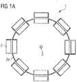
- FIG. 1a shows a schematic representation of a braiding machine 1 according to the prior art.
- the braiding machine 1 has several, eight in the example shown, bobbins 2 as an example for braided material carriers. Each of these bobbins 2 serves as a carrier for braided material to be braided by means of the braiding machine 1 in a braiding center 3.
- the braiding center 3 can also be referred to as the braiding axis of the braiding machine and correspond to the longitudinal axis of the braiding machine 1 or lie parallel to it.
- the braiding center 3 corresponds to the center point of the circular path on which the bobbins 2 move around the braiding center 3.
- the bobbins 2 rotate at a constant speed around the braiding center / braiding axis 3.
- the braided material supplied is moved out of position by the rotation of the bobbins 2 around the rotating and braiding center 3 and the removal of the respective braided material along the braiding center 3 Technology intertwined as we know it.
- the coils 2 are made according to the schematic illustration Figure 1a carried by a coil carrier 2a.
- a braiding process can be carried out by rotating the bobbin carrier 2a and thus moving the bobbins 2 around the common braiding center 3.
- an immovable bobbin (not shown) can be provided so that the braided material provided by the plurality of bobbins 2 and the braided material provided by the immovable bobbin are interwoven in a known manner.
- the plurality of coils 2 are arranged on a first coil carrier 2a, for example an upper rim, and further coils 2 are arranged on a second coil carrier (not shown), for example a lower rim.
- a braiding process can be carried out in a known manner, for example by counter-rotating movement, for example opposite rotation, of the two common bobbin carriers.
- braiding machines known from the prior art, such as braiding machine 1
- a constant speed is used. This speed is selected so that the maximum load on the braiding machine is not exceeded.
- Known braiding machines are often limited to a maximum speed of 175 rpm and are operated at this maximum speed.
- a permissible centrifugal force of 221.43 N acts on each fully filled coil 2.
- This figure shows the centrifugal force at a constant speed (see speed curve 4) and a filling level of 100% is maximum and decreases with decreasing degree of filling of the coil 2. This means that when the coil 2 is completely filled / filled, the highest load occurs.
- FIG. 3 shows a first exemplary embodiment of a braiding machine 10.
- the basic structure of the braiding machine 10 is based on the structure of the braiding machine 1 from FIG Figure 1a , so that reference is made to the relevant statements.
- the braiding machine 10 from Figure 2 has bobbins 20 as an example of braided material carriers. Each of the bobbins 20 serves as a carrier for braided material to be braided.
- the bobbins 20 are driven by a drive 12 of the braiding machine 10 around a common braiding axis 30 / around a common braiding center 30, which according to FIG Figure 2 corresponds to the center of rotation of the coils 20, rotated.
- no speed is preselected and kept constant.
- the braiding machine 10 turns off Figure 2 , a centrifugal force acting on one or more of the coils 20 and caused by the rotation is kept constant.
- the braiding machine 10 has a control device 40 and a sensor 50.
- the sensor 50 repeatedly detects, for example continuously, the filling level of one or more of the coils 20.
- the sensor 50 is designed, for example, as a distance sensor.
- the sensor 50 can, for example, use a laser to detect the respective distance from the coils 20 moving past. Since the degree of filling of the coils 20 changes continuously, the distance detected by the sensor 50 also changes accordingly. In the following, it is assumed by way of example that the sensor 50 repeatedly detects the filling level of all coils 20. From this, the mass of each of the coils 20 can be determined either directly by the sensor 50 or by the control device 40.
- each coil 20 can, for example, be provided with a force sensor.
- the centrifugal force acting in each case can then be measured directly by means of the force sensor. That is, as an alternative or in addition to the sensor 50 (e.g. for reasons of redundancy), a sensor can be provided on each of the coils 20, which sensor directly measures the centrifugal force acting on the respective coil 20.
- the centrifugal force acting on the respective coil 20 can be determined by the control device 40 from the mass of a coil 20, knowing its radial distance r from the center of rotation, ie from the braiding center 30. From the mass of each coil 20, the control device can in principle derive the centrifugal force acting in each case for each coil 20.
- ⁇ 2 ⁇ ⁇ ⁇ n
- the circle number n (Pi) is known and constant.
- the mass m and centrifugal force F are directly proportional. This means that as the mass decreases, the centrifugal force F acting on a body decreases in direct proportion.
- the control device 40 determines the rotational speed n in such a way that the centrifugal force F, which acts on the coils 20 in each case, remains constant.
- the speed n of the braiding machine 10 can be increased as the bobbin filling level decreases. This increases productivity.
- the speed can be adjusted in a range from 150 rpm to 250 rpm or in a sub-range thereof during the braiding process.
- the degree of filling of all coils 20 is identical. In practice, this can occur, for example, when the braiding machine 10 is put into operation for the first time or when all of the bobbins 20 are exchanged and replaced by completely filled bobbins 20 at the same time. In this case, it is sufficient if only the degree of filling of one of the coils 20 is detected in each case. Alternatively, the degree of filling of all coils 20 can also be recorded. Regardless of this, according to this example it is in any case sufficient to know the mass of one of the coils 20 on the part of the control device 40 and to take it into account for the control.
- the control device 40 will adapt the speed n such that the centrifugal force F constant as the mass m of the coil (s) 20 decreases remain.
- the speed or the speed adjustment is a quadratic function but also the mass of the coil 20 or the loss of mass of the coil during production / during the braiding process (the mass or the loss of mass are proportional to ⁇ / 4 * (D 2 - d 2 )).
- D is the outside diameter of the bobbin when the bobbin is filled to the maximum. D decreases during the braiding process and is therefore not constant. D is the core diameter of the coil itself and is therefore constant. Thus, d can also be understood as the diameter of the coil without filling material. In this way, from the known proportionality, the loss of mass from the outer diameter of the bobbin 20 with the bobbin filling present and the constant diameter of the bobbin 20 without filling material can be determined.
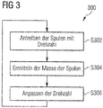
- a step S302 the drive of the braiding machine 10 drives the bobbins 20 in such a way that they move, for example rotate, about the common braiding center 30. You can rotate around the braiding center 30, for example, with an adjustable speed n.
- steps S304 and S306 the drive is controlled in such a way that a centrifugal force acting on at least one of the coils 20 remains at least almost constant.
- the filling level of the coils 20 is first detected by means of the sensor 50 in step S304.
- control device 40 can determine the adapted speed n directly in step S306, since the radial distance r to the braiding center 30 is known and constant, the mass m has been determined and the centrifugal force F is kept constant. That is to say, for the latter, the value that was previously available and, for example, selected at the beginning for the braiding machine 10 is used.
- step S302 the braiding machine 10 is driven at the adapted speed n.
- steps S302 to S306 can be repeated continuously during the braiding process.
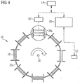
- FIG 4 a second embodiment of the braiding machine 10 is shown.
- the braiding machine 10 from Figure 4 is based on the braiding machine 10 Figure 2 . Accordingly, identical reference symbols are used for the identical elements and the braiding machine is also designated with the same reference symbol.
- the braiding machine 10 from Figure 4 has a slightly adapted algorithm.
- the braiding machine 10 can optionally be made from Figure 4 also have an unbalance sensor 60.
- the bobbins 20 of the braiding machine 10 purely by way of example, at least partially have a different degree of filling.
- the adapted algorithm is adapted in such a way that the filling level of all coils 20 is detected by means of the sensor 50 (this corresponds to a possible procedure from Figure 2 ), but only the degree of filling of the maximum filled coil 20a and thus the maximum mass of all coils 20 is taken into account for determining the speed.
- the adaptable speed is determined from the degree of filling of the coil 20a with the maximum degree of filling and thus of the coil 20a with maximum mass. If one of the coils 20 is exchanged, the coil 20a of maximum mass can change.
- the control device 40 can continue to use the largest mass m_max of the determined masses m to determine the adapted speed as follows.
- the control device 40 can determine the adapted speed n directly, since the radial distance r to the braiding center 30 is known and constant, the greatest mass m_max is known and the centrifugal force F is kept constant. That is to say, for the latter, the value that was previously available and, for example, selected at the beginning for the braiding machine 10 is used.
- an imbalance in the braiding machine 10 can be determined with the aid of the imbalance sensor 60.
- This imbalance results from the different degree of filling and thus the different mass of the coils 20. As the speed increases the imbalance increases, this can optionally be monitored.
- the control device 40 can take the imbalance into account when adapting the speed n. It is conceivable, for example, that with the aid of the unbalance sensor 60 it is established that a maximum permissible unbalance is exceeded if the speed determined by the control device were / is used. The control device 40 can then reduce the speed in such a way that the maximum permissible imbalance is not exceeded.
- FIGS Figures 5a to 5d illustrate the advantages of the braiding machines 10 of FIGS Figures 2 and 4th .
- FIG 5b shows the curve 110 of the centrifugal force of the braiding machines 10 of FIG Figures 2 and 4 in comparison to the curve 100 of the centrifugal force in the braiding machine 1 Figure 1a . It can be seen that the centrifugal force in the braiding machines 10 remains constant regardless of the degree of filling of the bobbins 20 (constant centrifugal force Fk), while the centrifugal force of the braiding machine 1 decreases with decreasing degree of filling (decreasing curve illustrated by multiplying centrifugal force F by a constant value a ⁇ 1).
- the extent of the increase in productivity is shown purely as an example Figure 5d .
- the course 300 of the productivity of the braiding machine 1 is constant regardless of the degree of filling of the bobbins 2, since the speed is constant.
- the course 310 of the productivity in the braiding machines 10 increases as the filling level of the bobbins 20 decreases. With a degree of filling of 100% to less than 85%, the productivity of the braiding machines 10 is still slightly lower than that of the braiding machine 1, but with a degree of filling of 85%, the productivity levels out.
- the braiding machines 10 could also start immediately with the maximum permissible speed. An increase in productivity would thus be achieved immediately (when the braiding machines 10 are started).
- the productivity advantage of the braiding machines 10 compared with the braiding machine 1 continues to increase.
- the braiding machine 10 could be operated at a constant speed from reaching a certain limit speed until the empty detection (degree of filling 0%) is reached.
- the course 320 of the productivity averaged over the braiding process shows that the averaged productivity of the braiding machines 10 is greater than the constant productivity of the braiding machine 1. Averaged over the entire process, a considerable increase in productivity of up to 21% can be achieved.
Landscapes
- Engineering & Computer Science (AREA)
- Textile Engineering (AREA)
- Braiding, Manufacturing Of Bobbin-Net Or Lace, And Manufacturing Of Nets By Knotting (AREA)
- Moulding By Coating Moulds (AREA)
- Knitting Machines (AREA)
Priority Applications (1)
| Application Number | Priority Date | Filing Date | Title |
|---|---|---|---|
| PL18706719T PL3585929T3 (pl) | 2017-02-27 | 2018-02-20 | Pleciarka |
Applications Claiming Priority (2)
| Application Number | Priority Date | Filing Date | Title |
|---|---|---|---|
| DE102017203161.1A DE102017203161B4 (de) | 2017-02-27 | 2017-02-27 | Flechtmaschine |
| PCT/EP2018/054173 WO2018153870A1 (de) | 2017-02-27 | 2018-02-20 | Flechtmaschine |
Publications (2)
| Publication Number | Publication Date |
|---|---|
| EP3585929A1 EP3585929A1 (de) | 2020-01-01 |
| EP3585929B1 true EP3585929B1 (de) | 2021-08-25 |
Family
ID=61258231
Family Applications (1)
| Application Number | Title | Priority Date | Filing Date |
|---|---|---|---|
| EP18706719.4A Active EP3585929B1 (de) | 2017-02-27 | 2018-02-20 | Flechtmaschine |
Country Status (13)
| Country | Link |
|---|---|
| US (1) | US11149365B2 (pl) |
| EP (1) | EP3585929B1 (pl) |
| JP (1) | JP7074775B2 (pl) |
| KR (1) | KR102482900B1 (pl) |
| CN (1) | CN110637116B (pl) |
| BR (1) | BR112019017736B1 (pl) |
| DE (1) | DE102017203161B4 (pl) |
| ES (1) | ES2898214T3 (pl) |
| HU (1) | HUE057031T2 (pl) |
| MX (1) | MX393904B (pl) |
| PL (1) | PL3585929T3 (pl) |
| RU (1) | RU2750018C2 (pl) |
| WO (1) | WO2018153870A1 (pl) |
Families Citing this family (1)
| Publication number | Priority date | Publication date | Assignee | Title |
|---|---|---|---|---|
| DE102020133096B4 (de) | 2020-12-11 | 2025-10-16 | Acandis Gmbh | Verfahren zur Herstellung eines Stents sowie computerlesbares Speichermedium |
Family Cites Families (23)
| Publication number | Priority date | Publication date | Assignee | Title |
|---|---|---|---|---|
| US1364291A (en) | 1921-01-04 | mccahey | ||
| US1485576A (en) * | 1919-09-27 | 1924-03-04 | Wendelburg Alex | Braiding machine |
| US2258018A (en) * | 1940-04-24 | 1941-10-07 | Smith King Company | Braider carrier |
| DE2162170A1 (de) | 1971-12-15 | 1973-06-20 | Spirka Masch Vorrichtungsbau | Schnellflechtmaschine zum umflechten von strangfoermigem gut |
| DE2903807A1 (de) | 1979-02-01 | 1980-08-14 | Felten & Guilleaume Carlswerk | Verfahren zum unwuchtausgleich eines bandwicklers und hierzu eingerichteter bandwickler |
| US4266461A (en) * | 1979-07-05 | 1981-05-12 | Karg Corporation | Tandem braiding system and components thereof |
| JPS6266922A (ja) * | 1985-09-18 | 1987-03-26 | Tokai Rubber Ind Ltd | 編組補強長尺体の編組装置及び編組方法 |
| US4716807A (en) * | 1986-12-17 | 1988-01-05 | Mayer Wildman Industries, Inc. | Speed control apparatus and method for braiding machine |
| US4903473A (en) * | 1988-09-01 | 1990-02-27 | Stolberger Maschinenfabrik Gmbh & Co Kg | Method for controlling a cage stranding machine |
| DE3900060A1 (de) * | 1989-01-03 | 1990-07-05 | Stolberger Maschf & Co Kg | Einrichtung zum bebaendern eines durchlaufenden materialstranges |
| JPH0674542B2 (ja) | 1990-08-25 | 1994-09-21 | 村田機械株式会社 | 組物構造体の組成方法 |
| FR2804133B1 (fr) | 2000-01-20 | 2002-04-05 | Inst Textile De France | Machine de tressage perfectionnee |
| US6360644B1 (en) * | 2000-03-31 | 2002-03-26 | American Metric Corporation | Braiding machine |
| DE102005058223A1 (de) | 2005-12-06 | 2007-06-14 | Maschinenfabrik Niehoff Gmbh & Co. Kg | Flechtmaschine |
| JP2008150715A (ja) | 2006-12-14 | 2008-07-03 | Nippon Mayer Ltd | トーションレース機におけるボビンの糸上がり監視装置 |
| CN201447562U (zh) | 2009-05-31 | 2010-05-05 | 梁东昭 | 高速编织机 |
| CN102587032B (zh) | 2011-01-13 | 2013-09-18 | 江苏苏净集团有限公司 | 废水处理填料编织机及其使用方法 |
| JP5437303B2 (ja) * | 2011-03-31 | 2014-03-12 | 三菱電機株式会社 | 縒線装置 |
| RU2519888C2 (ru) | 2012-09-18 | 2014-06-20 | Федеральное государственное бюджетное учреждение науки институт земного магнетизма, оиносферы и распространения радиоволн им. Н.В.Пушкова Российской академии наук ( ИЗМИРАН ). | Устройство для изготовления торсионых подвесов чувствительных элементов приборов |
| CN203700706U (zh) | 2013-10-25 | 2014-07-09 | 天津市宝坻区同利服装辅料厂 | 向心盘编织机 |
| GB2524576B (en) * | 2014-03-28 | 2018-11-14 | Jdr Cable Systems Ltd | Braiding machine |
| DE102017202632B4 (de) * | 2017-02-17 | 2020-10-29 | Leoni Kabel Gmbh | Flechtmaschine sowie Verfahren zur Herstellung eines Geflechts |
| JP6990959B2 (ja) * | 2017-11-30 | 2022-01-12 | Nittoku株式会社 | 撚り線装置及び撚り線の製造方法 |
-
2017
- 2017-02-27 DE DE102017203161.1A patent/DE102017203161B4/de active Active
-
2018
- 2018-02-20 RU RU2019130335A patent/RU2750018C2/ru active
- 2018-02-20 EP EP18706719.4A patent/EP3585929B1/de active Active
- 2018-02-20 BR BR112019017736-1A patent/BR112019017736B1/pt active IP Right Grant
- 2018-02-20 CN CN201880027926.6A patent/CN110637116B/zh active Active
- 2018-02-20 WO PCT/EP2018/054173 patent/WO2018153870A1/de not_active Ceased
- 2018-02-20 MX MX2019010135A patent/MX393904B/es unknown
- 2018-02-20 JP JP2019567780A patent/JP7074775B2/ja active Active
- 2018-02-20 HU HUE18706719A patent/HUE057031T2/hu unknown
- 2018-02-20 KR KR1020197028155A patent/KR102482900B1/ko active Active
- 2018-02-20 PL PL18706719T patent/PL3585929T3/pl unknown
- 2018-02-20 US US16/488,883 patent/US11149365B2/en active Active
- 2018-02-20 ES ES18706719T patent/ES2898214T3/es active Active
Non-Patent Citations (1)
| Title |
|---|
| None * |
Also Published As
| Publication number | Publication date |
|---|---|
| ES2898214T3 (es) | 2022-03-04 |
| HUE057031T2 (hu) | 2022-04-28 |
| JP7074775B2 (ja) | 2022-05-24 |
| BR112019017736A2 (pt) | 2020-06-02 |
| DE102017203161A1 (de) | 2018-08-30 |
| CN110637116B (zh) | 2021-08-13 |
| PL3585929T3 (pl) | 2022-01-24 |
| KR102482900B1 (ko) | 2022-12-29 |
| RU2750018C2 (ru) | 2021-06-21 |
| US11149365B2 (en) | 2021-10-19 |
| KR20190117742A (ko) | 2019-10-16 |
| EP3585929A1 (de) | 2020-01-01 |
| CN110637116A (zh) | 2019-12-31 |
| MX393904B (es) | 2025-03-24 |
| JP2020508406A (ja) | 2020-03-19 |
| WO2018153870A1 (de) | 2018-08-30 |
| MX2019010135A (es) | 2020-02-13 |
| RU2019130335A3 (pl) | 2021-03-29 |
| RU2019130335A (ru) | 2021-03-29 |
| DE102017203161B4 (de) | 2018-10-31 |
| US20200024778A1 (en) | 2020-01-23 |
| BR112019017736B1 (pt) | 2023-02-23 |
Similar Documents
| Publication | Publication Date | Title |
|---|---|---|
| EP3168338B1 (de) | Arbeitsstelle einer doppeldrahtzwirn- oder kabliermaschine | |
| DE2225918C3 (de) | Verfahren für den Abzug fadenförmigen Materials von einem Wickelkörper einer Speichereinrichtung für Textilmaschinen und Einrichtung zur Durchführung des Verfahrens | |
| DE2715988C2 (de) | Vorrichtung zum Steuern des Bandauftrages bei einer Schärmaschine | |
| EP3168339B1 (de) | Verfahren zum betreiben einer spindel einer doppeldrahtzwirn- oder kabliermaschine | |
| DE2736416A1 (de) | Verfahren und vorrichtung fuer die steuerung von strickmaschinen | |
| EP0308609A2 (de) | Fadenliefervorrichtung für Textilmaschinen mit zeitlich unterschiedlichem Fadenverbrauch, insb. Strick-und Wirkmaschinen | |
| DE2608590A1 (de) | Fadenliefervorrichtung, insbesondere fuer strickmaschinen | |
| EP2987757A1 (de) | Paraffiniereinrichtung für eine kreuzspulen herstellende textilmaschine | |
| DE102015122391B4 (de) | Verfahren zur Steuerung eines Anspinnprozesses zum Wiederanspinnen eines Garns an einer Spinnmaschine | |
| EP3585929B1 (de) | Flechtmaschine | |
| EP4122858B1 (de) | Verfahren zum betreiben einer arbeitsstelle einer spulmaschine sowie spulmaschine | |
| EP0386519B1 (de) | Verfahren und Vorrichtung zum Aufwickeln von vorbestimmten Garnlängen in Lagen auf einer Spule | |
| EP0247404B1 (de) | Fadenspannungs-Reguliereinrichtung für Strickmaschinen | |
| DE2831604C2 (de) | Verfahren zur Steuerung der Antriebsdrehzahl einer Verseilmaschine und Vorrichtung zur Ausübung des Verfahrens | |
| DE2635200C2 (de) | Fadenzuführeinrichtung | |
| EP0217373B1 (de) | Fadenliefervorrichtung für Textilmaschinen | |
| DE19635373C2 (de) | Vorrichtung zum Ausgleichen von Fadenverbrauchs- und Fadenspannungsschwankungen bei der Zuführung von fadenförmigem Material | |
| DE2851228C2 (de) | Abstreifer zum Entfernen von Unterwindungen von dem Unterwindebereich einer Ringspinn- oder -zwirnspindel | |
| AT521026B1 (de) | Vorrichtung zur Herstellung einer geflochtenen Ummantelung | |
| EP3269853A1 (de) | Verfahren zum starten einer spindel einer kablier- oder doppeldrahtzwirnmaschine | |
| DE102005049567A1 (de) | Verfahren und Vorrichtung zur Regelung der Spulendichte einer Garnspule | |
| DE2335204C3 (de) | Fadenliefer- und -speichervorrichtung | |
| DE900897C (de) | Umlaufender Nadelfadengeber, Fadenspannungseinrichtung fuer umlaufende Nadelfadengeber und Naehmaschine mit Nadelfaden-geber und Fadenspannungseinrichtung | |
| DE7606285U1 (pl) | ||
| EP3121315A1 (de) | Spinnmaschine, falschdralleinrichtung und fangeinrichtung |
Legal Events
| Date | Code | Title | Description |
|---|---|---|---|
| STAA | Information on the status of an ep patent application or granted ep patent |
Free format text: STATUS: UNKNOWN |
|
| STAA | Information on the status of an ep patent application or granted ep patent |
Free format text: STATUS: THE INTERNATIONAL PUBLICATION HAS BEEN MADE |
|
| PUAI | Public reference made under article 153(3) epc to a published international application that has entered the european phase |
Free format text: ORIGINAL CODE: 0009012 |
|
| STAA | Information on the status of an ep patent application or granted ep patent |
Free format text: STATUS: REQUEST FOR EXAMINATION WAS MADE |
|
| 17P | Request for examination filed |
Effective date: 20190924 |
|
| AK | Designated contracting states |
Kind code of ref document: A1 Designated state(s): AL AT BE BG CH CY CZ DE DK EE ES FI FR GB GR HR HU IE IS IT LI LT LU LV MC MK MT NL NO PL PT RO RS SE SI SK SM TR |
|
| AX | Request for extension of the european patent |
Extension state: BA ME |
|
| RAP1 | Party data changed (applicant data changed or rights of an application transferred) |
Owner name: MASCHINENFABRIK NIEHOFF GMBH & CO. KG |
|
| DAV | Request for validation of the european patent (deleted) | ||
| DAX | Request for extension of the european patent (deleted) | ||
| STAA | Information on the status of an ep patent application or granted ep patent |
Free format text: STATUS: EXAMINATION IS IN PROGRESS |
|
| 17Q | First examination report despatched |
Effective date: 20201020 |
|
| GRAP | Despatch of communication of intention to grant a patent |
Free format text: ORIGINAL CODE: EPIDOSNIGR1 |
|
| STAA | Information on the status of an ep patent application or granted ep patent |
Free format text: STATUS: GRANT OF PATENT IS INTENDED |
|
| INTG | Intention to grant announced |
Effective date: 20210409 |
|
| GRAS | Grant fee paid |
Free format text: ORIGINAL CODE: EPIDOSNIGR3 |
|
| GRAA | (expected) grant |
Free format text: ORIGINAL CODE: 0009210 |
|
| STAA | Information on the status of an ep patent application or granted ep patent |
Free format text: STATUS: THE PATENT HAS BEEN GRANTED |
|
| AK | Designated contracting states |
Kind code of ref document: B1 Designated state(s): AL AT BE BG CH CY CZ DE DK EE ES FI FR GB GR HR HU IE IS IT LI LT LU LV MC MK MT NL NO PL PT RO RS SE SI SK SM TR |
|
| REG | Reference to a national code |
Ref country code: CH Ref legal event code: EP |
|
| REG | Reference to a national code |
Ref country code: DE Ref legal event code: R096 Ref document number: 502018006705 Country of ref document: DE |
|
| REG | Reference to a national code |
Ref country code: IE Ref legal event code: FG4D Free format text: LANGUAGE OF EP DOCUMENT: GERMAN Ref country code: AT Ref legal event code: REF Ref document number: 1423901 Country of ref document: AT Kind code of ref document: T Effective date: 20210915 |
|
| REG | Reference to a national code |
Ref country code: LT Ref legal event code: MG9D |
|
| REG | Reference to a national code |
Ref country code: NL Ref legal event code: MP Effective date: 20210825 |
|
| PG25 | Lapsed in a contracting state [announced via postgrant information from national office to epo] |
Ref country code: NO Free format text: LAPSE BECAUSE OF FAILURE TO SUBMIT A TRANSLATION OF THE DESCRIPTION OR TO PAY THE FEE WITHIN THE PRESCRIBED TIME-LIMIT Effective date: 20211125 Ref country code: PT Free format text: LAPSE BECAUSE OF FAILURE TO SUBMIT A TRANSLATION OF THE DESCRIPTION OR TO PAY THE FEE WITHIN THE PRESCRIBED TIME-LIMIT Effective date: 20211227 Ref country code: LT Free format text: LAPSE BECAUSE OF FAILURE TO SUBMIT A TRANSLATION OF THE DESCRIPTION OR TO PAY THE FEE WITHIN THE PRESCRIBED TIME-LIMIT Effective date: 20210825 Ref country code: BG Free format text: LAPSE BECAUSE OF FAILURE TO SUBMIT A TRANSLATION OF THE DESCRIPTION OR TO PAY THE FEE WITHIN THE PRESCRIBED TIME-LIMIT Effective date: 20211125 Ref country code: SE Free format text: LAPSE BECAUSE OF FAILURE TO SUBMIT A TRANSLATION OF THE DESCRIPTION OR TO PAY THE FEE WITHIN THE PRESCRIBED TIME-LIMIT Effective date: 20210825 Ref country code: RS Free format text: LAPSE BECAUSE OF FAILURE TO SUBMIT A TRANSLATION OF THE DESCRIPTION OR TO PAY THE FEE WITHIN THE PRESCRIBED TIME-LIMIT Effective date: 20210825 Ref country code: HR Free format text: LAPSE BECAUSE OF FAILURE TO SUBMIT A TRANSLATION OF THE DESCRIPTION OR TO PAY THE FEE WITHIN THE PRESCRIBED TIME-LIMIT Effective date: 20210825 Ref country code: FI Free format text: LAPSE BECAUSE OF FAILURE TO SUBMIT A TRANSLATION OF THE DESCRIPTION OR TO PAY THE FEE WITHIN THE PRESCRIBED TIME-LIMIT Effective date: 20210825 |
|
| PG25 | Lapsed in a contracting state [announced via postgrant information from national office to epo] |
Ref country code: LV Free format text: LAPSE BECAUSE OF FAILURE TO SUBMIT A TRANSLATION OF THE DESCRIPTION OR TO PAY THE FEE WITHIN THE PRESCRIBED TIME-LIMIT Effective date: 20210825 Ref country code: GR Free format text: LAPSE BECAUSE OF FAILURE TO SUBMIT A TRANSLATION OF THE DESCRIPTION OR TO PAY THE FEE WITHIN THE PRESCRIBED TIME-LIMIT Effective date: 20211126 |
|
| REG | Reference to a national code |
Ref country code: ES Ref legal event code: FG2A Ref document number: 2898214 Country of ref document: ES Kind code of ref document: T3 Effective date: 20220304 |
|
| PG25 | Lapsed in a contracting state [announced via postgrant information from national office to epo] |
Ref country code: NL Free format text: LAPSE BECAUSE OF FAILURE TO SUBMIT A TRANSLATION OF THE DESCRIPTION OR TO PAY THE FEE WITHIN THE PRESCRIBED TIME-LIMIT Effective date: 20210825 |
|
| REG | Reference to a national code |
Ref country code: HU Ref legal event code: AG4A Ref document number: E057031 Country of ref document: HU |
|
| PG25 | Lapsed in a contracting state [announced via postgrant information from national office to epo] |
Ref country code: DK Free format text: LAPSE BECAUSE OF FAILURE TO SUBMIT A TRANSLATION OF THE DESCRIPTION OR TO PAY THE FEE WITHIN THE PRESCRIBED TIME-LIMIT Effective date: 20210825 |
|
| REG | Reference to a national code |
Ref country code: DE Ref legal event code: R097 Ref document number: 502018006705 Country of ref document: DE |
|
| PG25 | Lapsed in a contracting state [announced via postgrant information from national office to epo] |
Ref country code: SM Free format text: LAPSE BECAUSE OF FAILURE TO SUBMIT A TRANSLATION OF THE DESCRIPTION OR TO PAY THE FEE WITHIN THE PRESCRIBED TIME-LIMIT Effective date: 20210825 Ref country code: SK Free format text: LAPSE BECAUSE OF FAILURE TO SUBMIT A TRANSLATION OF THE DESCRIPTION OR TO PAY THE FEE WITHIN THE PRESCRIBED TIME-LIMIT Effective date: 20210825 Ref country code: EE Free format text: LAPSE BECAUSE OF FAILURE TO SUBMIT A TRANSLATION OF THE DESCRIPTION OR TO PAY THE FEE WITHIN THE PRESCRIBED TIME-LIMIT Effective date: 20210825 Ref country code: AL Free format text: LAPSE BECAUSE OF FAILURE TO SUBMIT A TRANSLATION OF THE DESCRIPTION OR TO PAY THE FEE WITHIN THE PRESCRIBED TIME-LIMIT Effective date: 20210825 |
|
| PLBE | No opposition filed within time limit |
Free format text: ORIGINAL CODE: 0009261 |
|
| STAA | Information on the status of an ep patent application or granted ep patent |
Free format text: STATUS: NO OPPOSITION FILED WITHIN TIME LIMIT |
|
| 26N | No opposition filed |
Effective date: 20220527 |
|
| PG25 | Lapsed in a contracting state [announced via postgrant information from national office to epo] |
Ref country code: SI Free format text: LAPSE BECAUSE OF FAILURE TO SUBMIT A TRANSLATION OF THE DESCRIPTION OR TO PAY THE FEE WITHIN THE PRESCRIBED TIME-LIMIT Effective date: 20210825 |
|
| PG25 | Lapsed in a contracting state [announced via postgrant information from national office to epo] |
Ref country code: MC Free format text: LAPSE BECAUSE OF FAILURE TO SUBMIT A TRANSLATION OF THE DESCRIPTION OR TO PAY THE FEE WITHIN THE PRESCRIBED TIME-LIMIT Effective date: 20210825 |
|
| REG | Reference to a national code |
Ref country code: BE Ref legal event code: MM Effective date: 20220228 |
|
| GBPC | Gb: european patent ceased through non-payment of renewal fee |
Effective date: 20220220 |
|
| PG25 | Lapsed in a contracting state [announced via postgrant information from national office to epo] |
Ref country code: LU Free format text: LAPSE BECAUSE OF NON-PAYMENT OF DUE FEES Effective date: 20220220 |
|
| PG25 | Lapsed in a contracting state [announced via postgrant information from national office to epo] |
Ref country code: IE Free format text: LAPSE BECAUSE OF NON-PAYMENT OF DUE FEES Effective date: 20220220 Ref country code: GB Free format text: LAPSE BECAUSE OF NON-PAYMENT OF DUE FEES Effective date: 20220220 |
|
| PG25 | Lapsed in a contracting state [announced via postgrant information from national office to epo] |
Ref country code: BE Free format text: LAPSE BECAUSE OF NON-PAYMENT OF DUE FEES Effective date: 20220228 |
|
| P01 | Opt-out of the competence of the unified patent court (upc) registered |
Effective date: 20230510 |
|
| PG25 | Lapsed in a contracting state [announced via postgrant information from national office to epo] |
Ref country code: MK Free format text: LAPSE BECAUSE OF FAILURE TO SUBMIT A TRANSLATION OF THE DESCRIPTION OR TO PAY THE FEE WITHIN THE PRESCRIBED TIME-LIMIT Effective date: 20210825 Ref country code: CY Free format text: LAPSE BECAUSE OF FAILURE TO SUBMIT A TRANSLATION OF THE DESCRIPTION OR TO PAY THE FEE WITHIN THE PRESCRIBED TIME-LIMIT Effective date: 20210825 |
|
| PG25 | Lapsed in a contracting state [announced via postgrant information from national office to epo] |
Ref country code: MT Free format text: LAPSE BECAUSE OF FAILURE TO SUBMIT A TRANSLATION OF THE DESCRIPTION OR TO PAY THE FEE WITHIN THE PRESCRIBED TIME-LIMIT Effective date: 20210825 |
|
| PGFP | Annual fee paid to national office [announced via postgrant information from national office to epo] |
Ref country code: DE Payment date: 20250218 Year of fee payment: 8 |
|
| PGFP | Annual fee paid to national office [announced via postgrant information from national office to epo] |
Ref country code: RO Payment date: 20250213 Year of fee payment: 8 |
|
| PGFP | Annual fee paid to national office [announced via postgrant information from national office to epo] |
Ref country code: ES Payment date: 20250318 Year of fee payment: 8 |
|
| PGFP | Annual fee paid to national office [announced via postgrant information from national office to epo] |
Ref country code: AT Payment date: 20250217 Year of fee payment: 8 Ref country code: CH Payment date: 20250301 Year of fee payment: 8 |
|
| PGFP | Annual fee paid to national office [announced via postgrant information from national office to epo] |
Ref country code: PL Payment date: 20250211 Year of fee payment: 8 Ref country code: FR Payment date: 20250219 Year of fee payment: 8 Ref country code: CZ Payment date: 20250211 Year of fee payment: 8 |
|
| PGFP | Annual fee paid to national office [announced via postgrant information from national office to epo] |
Ref country code: IT Payment date: 20250228 Year of fee payment: 8 |
|
| PGFP | Annual fee paid to national office [announced via postgrant information from national office to epo] |
Ref country code: TR Payment date: 20250212 Year of fee payment: 8 |
|
| REG | Reference to a national code |
Ref country code: CH Ref legal event code: U11 Free format text: ST27 STATUS EVENT CODE: U-0-0-U10-U11 (AS PROVIDED BY THE NATIONAL OFFICE) Effective date: 20260301 |
|
| PGFP | Annual fee paid to national office [announced via postgrant information from national office to epo] |
Ref country code: HU Payment date: 20260213 Year of fee payment: 9 |