EP3584144B1 - Vordere karosseriestruktur eines fahrzeuges - Google Patents
Vordere karosseriestruktur eines fahrzeuges Download PDFInfo
- Publication number
- EP3584144B1 EP3584144B1 EP18777672.9A EP18777672A EP3584144B1 EP 3584144 B1 EP3584144 B1 EP 3584144B1 EP 18777672 A EP18777672 A EP 18777672A EP 3584144 B1 EP3584144 B1 EP 3584144B1
- Authority
- EP
- European Patent Office
- Prior art keywords
- wheel
- vehicle
- air
- wheel house
- traveling
- Prior art date
- Legal status (The legal status is an assumption and is not a legal conclusion. Google has not performed a legal analysis and makes no representation as to the accuracy of the status listed.)
- Active
Links
Images




Classifications
-
- B—PERFORMING OPERATIONS; TRANSPORTING
- B62—LAND VEHICLES FOR TRAVELLING OTHERWISE THAN ON RAILS
- B62D—MOTOR VEHICLES; TRAILERS
- B62D35/00—Vehicle bodies characterised by streamlining
- B62D35/02—Streamlining the undersurfaces
-
- B—PERFORMING OPERATIONS; TRANSPORTING
- B60—VEHICLES IN GENERAL
- B60R—VEHICLES, VEHICLE FITTINGS, OR VEHICLE PARTS, NOT OTHERWISE PROVIDED FOR
- B60R13/00—Elements for body-finishing, identifying, or decorating; Arrangements or adaptations for advertising purposes
- B60R13/08—Insulating elements, e.g. for sound insulation
- B60R13/0861—Insulating elements, e.g. for sound insulation for covering undersurfaces of vehicles, e.g. wheel houses
-
- B—PERFORMING OPERATIONS; TRANSPORTING
- B60—VEHICLES IN GENERAL
- B60R—VEHICLES, VEHICLE FITTINGS, OR VEHICLE PARTS, NOT OTHERWISE PROVIDED FOR
- B60R19/00—Wheel guards; Radiator guards, e.g. grilles; Obstruction removers; Fittings damping bouncing force in collisions
- B60R19/02—Bumpers, i.e. impact receiving or absorbing members for protecting vehicles or fending off blows from other vehicles or objects
- B60R19/24—Arrangements for mounting bumpers on vehicles
-
- B—PERFORMING OPERATIONS; TRANSPORTING
- B62—LAND VEHICLES FOR TRAVELLING OTHERWISE THAN ON RAILS
- B62D—MOTOR VEHICLES; TRAILERS
- B62D21/00—Understructures, i.e. chassis frame on which a vehicle body may be mounted
- B62D21/09—Means for mounting load bearing surfaces
-
- B—PERFORMING OPERATIONS; TRANSPORTING
- B62—LAND VEHICLES FOR TRAVELLING OTHERWISE THAN ON RAILS
- B62D—MOTOR VEHICLES; TRAILERS
- B62D25/00—Superstructure or monocoque structure sub-units; Parts or details thereof not otherwise provided for
- B62D25/08—Front or rear portions
- B62D25/16—Mud-guards or wings; Wheel cover panels
-
- B—PERFORMING OPERATIONS; TRANSPORTING
- B62—LAND VEHICLES FOR TRAVELLING OTHERWISE THAN ON RAILS
- B62D—MOTOR VEHICLES; TRAILERS
- B62D25/00—Superstructure or monocoque structure sub-units; Parts or details thereof not otherwise provided for
- B62D25/08—Front or rear portions
- B62D25/082—Engine compartments
-
- Y—GENERAL TAGGING OF NEW TECHNOLOGICAL DEVELOPMENTS; GENERAL TAGGING OF CROSS-SECTIONAL TECHNOLOGIES SPANNING OVER SEVERAL SECTIONS OF THE IPC; TECHNICAL SUBJECTS COVERED BY FORMER USPC CROSS-REFERENCE ART COLLECTIONS [XRACs] AND DIGESTS
- Y02—TECHNOLOGIES OR APPLICATIONS FOR MITIGATION OR ADAPTATION AGAINST CLIMATE CHANGE
- Y02T—CLIMATE CHANGE MITIGATION TECHNOLOGIES RELATED TO TRANSPORTATION
- Y02T10/00—Road transport of goods or passengers
- Y02T10/80—Technologies aiming to reduce greenhouse gasses emissions common to all road transportation technologies
- Y02T10/88—Optimized components or subsystems, e.g. lighting, actively controlled glasses
Definitions
- the present invention relates to a vehicle front body structure.
- a traveling vehicle travels against traveling air that generates an aerodynamic drag.
- the aerodynamic drag has a considerable effect on fuel consumption of a vehicle, in particular, when the vehicle is traveling at a high speed. Measures have been taken to reduce the aerodynamic drag by, for example, suppressing the turbulent air in the flank of the vehicle body.
- One of the causes of the turbulent air in the flank of the vehicle body is the air flowing out of a wheel house to the flank of the vehicle body.
- the traveling air from the front side flows beneath a front bumper then into the wheel house and also through an engine room then into the wheel house.
- the traveling air colliding against the front bumper is divided into right and left portions which then flows around the right and left corner ends of the front bumper and toward the rear side.
- a negative pressure is created in the rear side of the corner ends of the front bumper.
- the air flown into the wheel house is suctioned out of the wheel house through the front side of a front wheel by the negative pressure. This creates a vortex outside the vehicle at the wheel house.
- the vortex develops into a turbulent flow that flows along the flank of the vehicle body, thereby increasing the aerodynamic drag acting on the flank of the vehicle body.
- Patent Literature 1 discloses a vehicle body structure including ducts provided at right and left ends of a front bumper provided in the front part of the vehicle body, where the duct includes an inlet port for taking in traveling air from the front side and a discharge port opened in a rearward face of a wheel house housing a front wheel to face the forward face of the front wheel.
- traveling air taken in from the inlet port and discharged from the discharge port makes contact with the forward face of the front wheel, and thus forms an air curtain between the rearward face of the wheel house and the forward face of the front wheel to separate the inside of the wheel house and the outside of the vehicle.
- the structure disclosed in Patent Literature 1 suppresses the air, which has flown into the wheel house, flowing out through the front side of the front wheel to the outside of the vehicle. This suppresses collision of the air discharged out of the wheel house into a region in the laterally outer side of the front wheel and the air flowing along the flank of the vehicle body. Accordingly, the structure disclosed in Patent Literature 1 may reduce the aerodynamic drag caused by detachment of air and vortexes occurring in the flank of the vehicle body.
- Patent Literature 1 JP 2014-76728 A
- Patent Literature 1 solely cannot completely prevent the air flown into the wheel house from flowing out to the flank of the vehicle body.
- a large volume of air flows into the wheel house or when the pressure inside the wheel house is high, a large volume of air flows out to the flank of the vehicle body and might increase the aerodynamic drag.
- An object of the present disclosure is to provide a vehicle front body structure that suppresses, when the vehicle is traveling, flowing of the air from the front side of the vehicle body and the engine room into the wheel house, to suppress the volume of the air flowing out of the wheel house to the flank of the vehicle body, thereby suppressing air turbulence in the flank of the vehicle body to reduce the aerodynamic drag.
- a vehicle front body structure includes a front bumper disposed in a front portion of a vehicle body, wheel houses provided in right and left sides of the vehicle body, respectively, in a rear side of the front bumper, a pair of front side frames provided in right and left portions, respectively, in the rear side of the front bumper, each of the front side frames extending in the front-and-rear direction, a sub-frame disposed below the front side frames and between the right and left wheel houses, deflectors disposed below right and left ends of the front bumper, respectively to suppress flowing of traveling air from a front side into the wheel houses, splash shields provided between the respective front side frames and the sub-frame to suppress flowing of air from an engine room into the wheel houses, and ducts provided at the right and left ends of the front bumper, respectively and each including an intake port that takes in traveling air from the front side, and a discharge port that discharges the traveling air taken in from the intake port into the wheel houses.
- the splash shield extends toward the upper side from the upper portion of the sub-frame to separate the engine room from the wheel house.
- a plurality of recessed parts extending upward the upper side are provided in the lower edge of the splash shield.
- the plurality of recessed parts are disposed over a plurality of shaft members penetrating into the wheel house from the engine room.
- the discharge port of the duct has a vertically elongate shape to discharge traveling air to a vertically elongate region on the front portion of the front wheel in the wheel house.
- a vehicle front body structure according to an embodiment will be described in detail below. The description will be made on the front body structure in the left side of the vehicle illustrated in the drawings.
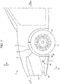
- the front part of a vehicle body 1 includes a hood 2 covering the upper face of the front part of the vehicle body, front fenders 3 covering the right and left side faces of the vehicle body (hereinafter, only the front fender 3 in the left side is illustrated), and a front bumper 4 covering the front part of the vehicle body, namely, from the front portion to the right and left side portions of the vehicle body.
- the front bumper 4 extends in the lateral direction and continues to the front fender 3.
- Wheel houses 5 each having an approximately semicircular shape and opened downward are provided in the flank of the vehicle body, each of the wheel houses 5 being provided across the boundary between the front bumper 4 and the front fender 3 (hereinafter, only the wheel house 5 in the left side is illustrated).
- Wheel arches 31 of the front fenders 3 each constitute the wheel house 5.
- Fender liners 32 are each coupled to the inside of the wheel arch 31 (hereinafter, only the fender liner 32 in the left side is illustrated).
- the fender liner 32 has an approximately cylindrical face to form the shape of the wheel house 5 (see FIG. 3 ).
- Front wheels 6 are each disposed in the wheel house 5 (hereinafter, only the front wheel 6 in the left side is illustrated).
- a brake rotor or a brake drum 61 constituting a braking device of the vehicle is provided in each of the front wheels 6.
- the vehicle body 1 includes a pair of right and left front side frames 11 each extending in the front-and-rear direction (hereinafter, only the front side frame 11 in the left side is illustrated), a sub-frame 12 disposed below the front side frames 11, and vehicle structural members 13 (hereinafter, only the vehicle structural member 13 in the left side is illustrated) each connecting the sub-frame 12 and one of the front side frames 11.
- a dash panel 14 extending in the lateral direction and separating an engine room Y from a vehicle interior Z is provided between the pair of front side frames 11.
- the sub-frame 12 includes a pair of side members 12a provided in the right and left sides, in the lateral direction, to extend in the front-and-rear direction of the vehicle (hereinafter, only the side member 12a in the left side is illustrated), and a cross member 12b extending in the lateral direction to connect rear portions of the side members 12a.
- a drive shaft 91, a steering rack 92, and a stabilizer 93 are provided as shaft members penetrating into the wheel houses 5 and 5 from inside the engine room Y.
- the shaft members 91, 92, and 93 are disposed in this order in the direction from the front side to the dash panel 14.
- the shaft members 91, 92, and 93 penetrate into the wheel houses 5 and 5 from inside the engine room Y to connect the right and left front wheels 6 and 6.
- Suspension arms 9 and 9 which are suspension members for the front wheels 6 and 6 are supported by the cross member 12b of the sub-frame 12.
- the vehicle body 1 includes members constituting a structure for improving the aerodynamic performance in the flank of the vehicle body.
- the members are deflectors 7 fixed below the right and left ends of the front bumper 4 (hereinafter, only the deflector 7 in the left side is illustrated), front and rear splash shields 81 and 82 provided to cover the space between the front side frames 11 and the sub-frame 12, and ducts 40 provided at the right and left ends of the front bumper 4 to take in the traveling air from the front side and discharge the traveling air into the wheel houses 5 (hereinafter, only the duct 40 in the left side is illustrated).
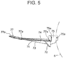
- the deflector 7 includes a horizontal portion 71 provided in front of the front wheel 6 to extend approximately in a horizontal direction, a first inclined portion 72 continuing from the rear end of the horizontal portion 71 and inclined downward at a large inclination angle toward the lower portion of the front wheel 6, a second inclined portion 73 provided further in the laterally inner side than the front wheel 6 and inclined downward at an inclination angle smaller than the inclination angle of the first inclined portion 72, and a transition portion 74 connecting the horizontal portion 71 and the first inclined portion 72 to the second inclined portion 73.
- a rear flange 75 is provided at the rear end of the deflector 7 to rise up from the horizontal portion 71 and the second inclined portion 73.
- the rear flange 75 is fastened to the fender liner 32 by plastic clips 75a 1 and 75a 1 .
- An inner flange 76 is provided at the rear end in the inner side of the deflector 7.
- the inner flange 76 is fastened to the front splash shield 81 by a plastic clip 76a 1 .
- the outer flange 77 is provided along the front end and the rim in the outer side of the deflector 7 to extend in the outer side from the horizontal portion 71 and the second inclined portion 73.
- the outer flange 77 is fastened to the front bumper 4 by plastic clips 77a 1 , ..., 77a 1 .
- the deflectors 7 are fixed to the front bumper 4, the fender liners 32 and 32, and the front splash shields 81 so as to cover the areas each extending from the right or left distal end of the bottom of the front bumper 4 to the front end of the wheel house 5.
- the front splash shields 81 are provided further in the front side, in the front-and-rear direction, than the drive shaft 91, and the rear splash shields 82 are provided further in the rear side, in the front-and-rear direction, than the drive shaft 91.
- the rear splash shield 82 is an example of the "splash shield" of the above aspect.
- the upper portion of the front splash shield 81 is fixed to the outer-lower portion of the front side frame 11 by a bolt (not illustrated) and the lower portion of the front splash shield 81 is fixed to the outer portion of the sub-frame 12 by a bolt (not illustrated).
- the front splash shield 81 is thereby disposed to cover the area which is between the front side frame 11 and the sub-frame 12 and further in the front side than the drive shaft 91 from the laterally outer side.
- the front side of the rear splash shield 82 is fastened to the vehicle structural member 13, which connects the front side frame 11 and the sub-frame 12, by bolts 83, ..., 83, and the rear side of the rear splash shield 82 is fixed to the upper face of the sub-frame 12 by a bolt 83.
- the rear splash shield 82 is thereby disposed to cover the area which is between the front side frame 11 and the sub-frame 12 and further in the rear side, in the front-and-rear direction, than the drive shaft 91.
- the rear splash shield 82 includes a vertical portion 82a that extends in the vertical direction to separate the engine room Y from the wheel house 5.
- a flange part 82b extends outward along the lateral direction from the upper end of the vertical portion 82a.
- the rear splash shield 82 is coupled by a bolt 83 to the vehicle structural member 13 via a fastening portion 82b' provided on the flange part 82b.
- the rear splash shield 82 includes a stepped portion 82c provided in the lower face of the vertical portion 82a, a first recessed part 82d provided in the front side of the stepped portion 82c and formed to half encircle the outer circumferential face of the steering rack 92 (formed in an approximately arc shape with an opening that allows the steering rack 92 to pass therethrough), and a second recessed part 82e provided in the rear side of the stepped portion 82c and formed to half encircle the outer circumferential face of the stabilizer 93 (formed in an approximately arc shape with an opening allowing the stabilizer 93 to pass therethrough).
- a flange 82f is provided at the rear end, in the front-and-rear direction, of the rear splash shield 82 at a place lower than the vertical portion 82a to extend in the rear side.
- a fastening portion 82f 1 provided on the flange 82f is coupled to the cross member 12b of the sub-frame 12 by a bolt 83.
- the front and rear splash shields 81 and 82 separate the engine room Y from the wheel houses 5.
- the ducts 40 are provided at the right and left ends of the front bumper 4.
- the ducts 40 each include an intake port 41, a discharge port 42, and a passage 43.
- the intake ports 41 are provided at both lateral ends of the front bumper 4 to open to the front side of the vehicle body.
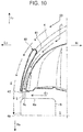
- the discharge port 42 of the duct 40 has a vertically elongate shape and is in front of the wheel house 5.
- the traveling air is discharged from the discharge port 42 to a vertically elongate region on the front portion 6a of the front wheel 6.
- the discharge port 42 of the duct 40 is formed so that the traveling air passing through the duct 40 collides against an edge 6c (R-end) between the front portion 6a and a flank 6b of the front wheel 6 facing the outside of the vehicle.
- the discharge port 42 has a shape laterally centered on the edge 6c of the front wheel 6 and having a 5 mm width from the center in both sides.
- FIG. 8 illustrates traveling air A flowing along the first inclined portion 72 of the deflector 7.
- FIG. 9 illustrates traveling air B flowing along the second inclined portion 73 of the deflector 7.
- the traveling air A from the front side collides against the front bumper 4, turns and flows along the flank of the vehicle body, and also flows beneath the front bumper 4.
- the traveling air A passes by the horizontal portion 71 of the deflector 7 to reach the first inclined portion 72 of the deflector 7, and then the traveling air A is deflected downward along the first inclined portion 72 to flow toward the front side of the front wheel 6.
- direct collision of the traveling air A against the front wheel 6 is avoided as indicated by an arrow A 1 , for example, and this suppresses the pressure rise in the wheel house 5.
- the traveling air B from the front side collides against the front bumper 4, turns and flows along the flank of the vehicle body, and also flows beneath the front bumper 4. Since the traveling air B passing by the second inclined portion 73 of the deflector 7 is inclined to flow beneath the suspension arm 9 and collision of the traveling air B against the deflector 7 like the traveling air A colliding against the first inclined portion 72 is avoided, the air smoothly flows along the deflector 7 from the distal end thereof to the rear side.
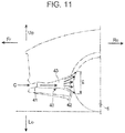
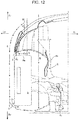
- the traveling air C from the front side collides against the front bumper 4 is taken in from the intake port 41 of the duct 40, and discharged from the discharge port 42 to make contact with the front wheel 6 in the wheel house 5.
- An air curtain c is thereby formed between the discharge port 42 of the duct 40 and the front wheel 6 to separate the inside of the wheel house 5 from the outside of the vehicle.
- the traveling air C from the front side is taken in from the intake port 41 of the duct 40 and discharged from the discharge port 42 as illustrated in FIG. 11 .
- the traveling air C is discharged through the vertically elongate opening of the discharge port 42.
- the air curtain c is provided in a vertically broad area in a side view of the vehicle body.
- the traveling air flowing in the laterally outer side along the first inclined portion 72 of the deflector 7 is deflected to avoid colliding against the front wheel 6 as indicated by the arrow A, thereby suppressing the pressure rise in the wheel house 5.
- the front and rear splash shields 81 and 82 suppress air E in the engine room Y from flowing into the wheel house 5, thereby suppressing the pressure rise in the wheel house 5.
- the traveling air C passing through the ducts 40 disposed at both ends of the front bumper 4 forms the air curtain c between the rearward face of the wheel house 5 and the forward face of the front wheel 6 to suppress the air C 1 , which has flown into the wheel house 5, from flowing out through the front side of the front wheel 6 to the flank of the vehicle body.
- the pressure in the wheel house 5 can be lowered while suppressing the volume of the traveling air flowing into the wheel house 5.
- Traveling air D which results from the traveling air colliding against the front bumper 4 and divided into the right and left flows, creates a negative pressure region d in the rear side of the corner end of the front bumper 4.
- This negative pressure region d can suction the air C 1 that has flown into the wheel house 5 out of the wheel house 5 through the front side of the front wheel 6.
- the air curtain c effectively suppresses the air in the wheel house 5 from flowing out to the flank of the vehicle body.
- the aerodynamic drag caused by detachment of air and vortexes occurring in the flank of the vehicle body is reduced.
- a vehicle front body structure includes a front bumper, wheel houses, a pair of front side frames, a sub-frame, deflectors, splash shields, and ducts.
- the front bumper is disposed in the front part of a vehicle.
- the wheel houses are provided in the right and left sides of the vehicle body, respectively, in the rear side of the front bumper.
- the pair of front side frames are provided in the right and left portions, respectively in the rear side of the front bumper, each of the front side frames extending in the front-and-rear direction.
- the sub-frame is disposed below the front side frames and between the right and left wheel houses.
- the deflectors are disposed below the right and left ends of the front bumper, respectively to suppress flowing of the traveling air from the front side into the wheel houses.
- the splash shields are disposed between the respective front side frames and the sub-frame to suppress flowing of the air from the engine room into the wheel houses.
- the ducts are provided at the right and left ends of the front bumper, respectively.
- Each of the ducts includes an intake port for taking in the traveling air from the front side, and a discharge port for discharging the traveling air, taken in from the intake port, into the wheel house.
- the splash shield extends toward the upper side from the upper portion of the sub-frame to separate the engine room from the wheel house.
- a plurality of recessed parts extending upward are provided in the lower edge of the splash shield.
- the plurality of recessed parts are disposed over a plurality of shaft members penetrating into the wheel houses from the engine room.
- the discharge port of the duct has a vertically elongate shape to discharge the traveling air to a vertically elongate region on the front portion of the front wheel disposed in the wheel house.
- the vehicle front body structure includes the deflectors provided below the right and left ends of the front bumper, the splash shields separating the wheel houses in the rear side of the front bumper from the engine room, and the ducts provided at the right and left ends of the front bumper.
- the deflectors suppress the traveling air from the front side from flowing into the wheel houses, and the splash shields suppress the air in the engine room from flowing into the wheel houses.
- the air discharged from the discharge port of the duct provided at the front bumper makes contact with the front wheel in the wheel house, to thereby form an air curtain between the discharge port of the duct and the front wheel to separate the inside of the wheel house from the outside of the vehicle.
- the splash shield extends toward the upper side from the upper portion of the sub-frame to separate the engine room from the wheel house.
- the splash shield has a plurality of recessed parts extending upward from the lower edge of the splash shield, where the recessed parts are disposed over a plurality of shaft members penetrating into the wheel houses from the engine room. This effectively suppresses the air in the engine room from flowing into the wheel houses.
- the discharge port of the duct has a vertically elongate shape to discharge the traveling air to a vertically elongate region on the front portion of the front wheel in the wheel house, thereby forming the above-mentioned air curtain vertically broad in a side view of the vehicle body. That is, the broad plane of the air curtain separates the wheel house from the flank of the vehicle body.
- the vehicle front body structure according to the above aspect further reliably suppresses the air from flowing out of the wheel house to the flank of the vehicle body.
- collision between the air flowing out of the wheel house to the flank of the vehicle body and the traveling air flowing in the flank of the vehicle body is suppressed, and thus air turbulence in the flank of the vehicle body is further reliably suppressed.
- the deflector in the vehicle front body structure of the above aspect, includes a first inclined portion that is inclined downward at a large inclination angle toward the lower portion of the front wheel positioned in the rear side of the deflector, and a second inclined portion that is provided adjacent to and laterally further inner than the first inclined portion and inclined downward at an inclination angle smaller than the inclination angle of the first inclined portion toward a space located laterally further inner than the front wheel in the wheel house.
- the deflector includes the first inclined portion inclined downward at a large inclination angle toward the lower portion of the front wheel positioned in the rear side of the deflector, and the second inclined portion that is provided adjacent to and laterally further inner than the first inclined portion and inclined downward at an inclination angle smaller than the inclination angle of the first inclined portion toward a space located laterally further inner than the front wheel in the wheel house.
- the first inclined portion suppresses flowing of the traveling air into the wheel house and avoids the traveling air directly colliding against the front wheel, and thereby suppressing the pressure rise in the wheel house.
- the second inclined portion moderately guides the traveling air in the laterally inner side to flow beneath the wheel house without disturbing the traveling air flow, and thus the aerodynamic drag caused by collision between the traveling air and the deflector is suppressed. Since the velocity of the traveling air flowing by the second inclined portion of the deflector is higher than the velocity of the air inside the wheel house, a low pressure is created in the wheel house in a region further in the rear side of the deflector. For example, the air that has been discharged out of the wheel house to the flank of the vehicle body can be suctioned into the wheel house or the rear side of the wheel house.
- air turbulence in the flank of the vehicle body can be suppressed not only at the front side but at the rear side of the wheel house. Furthermore, a portion of the traveling air flowing in the flank of the vehicle body can be suctioned into the wheel house or to the rear side of the wheel house, and thereby an effect of, for example, cooling a brake rotor or the like disposed in the wheel house can be obtained.
- the cross-section of the passage of the duct becomes laterally narrow toward the discharge port of the duct, and the discharge port of the duct is formed so that the traveling air passing through the duct collides against the edge of the front wheel when the vehicle is traveling straight, where the edge is between the front portion of the front wheel and the flank of the front wheel facing the outside of the vehicle.
- the discharge port of the duct is formed so that the traveling air passing through the duct collides against the edge of the front wheel when the vehicle is traveling straight, where the edge is between the front portion of the front wheel and the flank of the front wheel facing the outside of the vehicle. This suppresses, when the vehicle is traveling straight, the pressure rise in the wheel house and a preferable air curtain is formed. Accordingly, the vehicle front body structure according to the above aspect further effectively reduces the aerodynamic drag that has a considerable effect on fuel consumption when the vehicle is traveling at a high speed.
- the vehicle front body structure according to the above aspect prevents a state in which the traveling air flows into the wheel house when the air passing through the duct is discharged further in the laterally inner side than a predetermined width at the edge of the front wheel as well as a state in which an air curtain cannot reliably be generated when the air passing through the duct is discharged further in the laterally outer side than a predetermined width at the edge of the front wheel.
- the vehicle front body structure according to the above aspect can provide an air curtain in a most suitable region to suppress the air from flowing out of the wheel house to the flank of the vehicle.
- the discharge port of the duct is formed to be laterally narrow.
- the discharge port of the duct being vertically elongate and laterally small, the decrease in the velocity of the air discharged through the duct is suppressed.
- the vehicle front body structure according to the above aspect creates a high velocity air flow discharged through the duct to further reliably generate the air curtain.
- a vehicle front body structure includes a front bumper, wheel houses, a pair of front side frames, a sub-frame, deflectors, splash shields, and ducts.
- the front bumper is disposed in the front part, in the front-and-rear direction, of a vehicle.
- the wheel houses are provided in the right and left sides, in a lateral direction, of the vehicle in the rear side of the front bumper.
- the pair of front side frames are provided in the right and left, in the lateral direction, in the rear side of the front bumper, each of the front side frames extending in the front-and-rear direction.
- the sub-frame is disposed below the front side frames and between the right and left wheel houses.
- the deflectors are disposed below, in the vertical direction, the right and left ends of the front bumper to suppress flowing of the air from the front side into the wheel houses.
- the splash shields are disposed between the pair of front side frames and the sub-frame to suppress flowing of the air from the engine room into the wheel houses.
- the ducts are provided at the right and left ends of the front bumper.
- the duct causes the traveling air from the front side to collide against the front portion of the front wheel in the wheel house to form the air curtains between the rearward face of the wheel house and the front portion of the front wheel, thereby suppressing flowing of the air from the wheel house to the flank of the vehicle body.
- the vehicle front body structure includes the front bumper, the wheel houses provided at the right and left ends of the vehicle body in the rear side of the front bumper, the deflectors provided below the right and left ends of the front bumper to suppress the pressure rise in the wheel houses caused by the air flowing into the wheel houses, the splash shields that suppress the pressure rise in the wheel houses caused by the air in the engine room flowing into the wheel houses, and the ducts provided at the right and left ends of the front bumper and each causing the traveling air from the front side to collide against the front portion of the front wheel to form the air curtain.
- the formed air curtain suppresses flowing of the air out of the wheel house to the flank of the vehicle while the deflector and the splash shield suppress the volume of the air flowing into the wheel house, thereby suppressing the pressure rise in the wheel house.
- the air flowing out of the wheel house to the flank of the vehicle body is effectively suppressed.
- the pressure inside the wheel house can be reduced, so that the air that has flown out of the wheel house passing the air curtain through the front side of the front wheel to the flank of the vehicle body can be suctioned into the rear side of the front wheel in the wheel house.
- air turbulence in the flank of the vehicle body can be suppressed.
- the vehicle front body structure according to each of the above aspects suppresses the air from the front side and the air in the engine room from flowing into the wheel house, to suppress the volume of the air flowing out of the wheel house to the flank of the vehicle body when the vehicle is traveling.
- air turbulence in the flank of the vehicle body can be suppressed to reduce the aerodynamic drag.
Landscapes
- Engineering & Computer Science (AREA)
- Mechanical Engineering (AREA)
- Chemical & Material Sciences (AREA)
- Combustion & Propulsion (AREA)
- Transportation (AREA)
- Physics & Mathematics (AREA)
- Acoustics & Sound (AREA)
- Body Structure For Vehicles (AREA)
Claims (3)
- Vordere Fahrzeugkarosseriestruktur, welche aufweist:eine vordere Stoßstange (4), die in einem vorderen Abschnitt einer Fahrzeugkarosserie (1) angeordnet ist;Radkästen (5), die in rechten bzw. linken Seiten der Fahrzeugkarosserie auf einer hinteren Seite der vorderen Stoßstange vorgesehen sind;ein Paar vordere Seitenrahmen (11), die in rechten bzw. linken Abschnitten in der hinteren Seite der vorderen Stoßstange vorgesehen sind, wobei jeder der vorderen Seitenrahmen in der Vorn-und-Hinten-Richtung verläuft;einen Teilrahmen (12), der unter den vorderen Seitenrahmen und zwischen den rechten und linken Radkästen angeordnet ist;Deflektoren (7), die unter rechten und linken Enden der vorderen Stoßstange angeordnet sind, um jeweils das Strömen von Bewegungsluft von einer Vorderseite in die Radkästen zu unterbinden;Spritzschutzeinrichtungen (81, 82), die zwischen den jeweiligen vorderen Seitenrahmen und dem Teilrahmen vorgesehen sind, um das Strömen von Luft von einem Motorraum in die Radkästen zu unterbinden; undKanäle (40), die jeweils an den rechten bzw. linken Enden der vorderen Stoßstange vorgesehen sind, und jeweils einen Einlassstutzen (41) aufweisen, der Bewegungsluft von der Vorderseite aufnimmt, und einen Auslassstutzen (42), der die Bewegungsluft, die von dem Einlassstutzen aufgenommen wurde, in die Radkästen ausleitet,wobei sich die Spritzschutzeinrichtungen in Richtung einer oberen Seite von einem oberen Abschnitt des Teilrahmens erstrecken, um den Motorraum von den Radkästen zu trennen, wobei jede der Spritzschutzeinrichtungen eine Vielzahl von vertieften Teilen aufweist, die sich von einem unteren Rand der Spritzschutzeinrichtung nach oben erstrecken,die Vielzahl von vertieften Teilen über eine Vielzahl von Wellenelementen angeordnet sind, die aus dem Motorraum in die Radkästen eindringen, undder Auslassstutzen von jedem der Kanäle eine Form besitzt, die in der Vertikalrichtung länglich ist, um Bewegungsluft in einen Bereich, der in der Vertikalrichtung länglich ist, an einem vorderen Abschnitt des Vorderrads, das in dem Radkasten angeordnet ist, auszuleiten.
- Vordere Fahrzeugkarosseriestruktur nach Anspruch 1, wobei die Deflektoren jeweils einen ersten geneigten Abschnitt (72), der unter einem großen Neigungswinkel in Richtung eines unteren Abschnitts der Vorderrads nach unten geneigt ist, welcher in einer hinteren Seite des Deflektors positioniert ist, und einen zweiten geneigten Abschnitt (73) aufweisen, der neben und seitlich weiter innen als der erste geneigte Abschnitt vorgesehen ist und unter einem Neigungswinkel, der kleiner als der Neigungswinkel des ersten geneigten Abschnitts ist, nach unten in Richtung eines Raums geneigt ist, der sich seitlich weiter innen als das Vorderrad in dem Radkasten befindet.
- Vordere Fahrzeugkarosseriestruktur nach Anspruch 1 oder 2, wobei
ein Querschnitt einer Passage des Kanals seitlich in Richtung des Auslassstutzens des Kanals schmal wird, und
der Auslassstutzen des Kanals derart geformt ist, dass Bewegungsluft, welche den Kanal durchläuft, mit einer Kante des Vorderrads kollidiert, wenn das Fahrzeug geradeaus fährt, wobei die Kante zwischen dem vorderen Abschnitt des Vorderrads und einer Flanke des Vorderrads ist, die einer Außenseite des Fahrzeugs zugewandt ist.
Applications Claiming Priority (2)
| Application Number | Priority Date | Filing Date | Title |
|---|---|---|---|
| JP2017063584A JP6477762B2 (ja) | 2017-03-28 | 2017-03-28 | 車両の前部車体構造 |
| PCT/JP2018/006124 WO2018180026A1 (ja) | 2017-03-28 | 2018-02-21 | 車両の前部車体構造 |
Publications (3)
| Publication Number | Publication Date |
|---|---|
| EP3584144A1 EP3584144A1 (de) | 2019-12-25 |
| EP3584144A4 EP3584144A4 (de) | 2020-04-01 |
| EP3584144B1 true EP3584144B1 (de) | 2021-04-21 |
Family
ID=63676983
Family Applications (1)
| Application Number | Title | Priority Date | Filing Date |
|---|---|---|---|
| EP18777672.9A Active EP3584144B1 (de) | 2017-03-28 | 2018-02-21 | Vordere karosseriestruktur eines fahrzeuges |
Country Status (5)
| Country | Link |
|---|---|
| US (1) | US11084544B2 (de) |
| EP (1) | EP3584144B1 (de) |
| JP (1) | JP6477762B2 (de) |
| CN (1) | CN110461688B (de) |
| WO (1) | WO2018180026A1 (de) |
Families Citing this family (13)
| Publication number | Priority date | Publication date | Assignee | Title |
|---|---|---|---|---|
| EP3578446B1 (de) * | 2017-03-06 | 2022-08-10 | Mazda Motor Corporation | Reifendeflektorvorrichtung |
| JP6477762B2 (ja) * | 2017-03-28 | 2019-03-06 | マツダ株式会社 | 車両の前部車体構造 |
| KR102540890B1 (ko) * | 2018-10-29 | 2023-06-08 | 현대자동차주식회사 | 회전가림 방식 휠 가드 시스템 및 차량 |
| JP7127532B2 (ja) * | 2018-12-26 | 2022-08-30 | マツダ株式会社 | 車両の前部構造 |
| JP7176404B2 (ja) * | 2018-12-26 | 2022-11-22 | マツダ株式会社 | 自動車のデフレクタ構造 |
| KR102751056B1 (ko) * | 2019-12-16 | 2025-01-08 | 현대자동차주식회사 | 능동형 에어커튼 장치 및 능동형 에어커튼 시스템 |
| JP7397407B2 (ja) * | 2020-03-24 | 2023-12-13 | マツダ株式会社 | エンジンルーム排熱構造 |
| JP7396181B2 (ja) * | 2020-04-20 | 2023-12-12 | マツダ株式会社 | 車両の前部構造 |
| DE102020007450B4 (de) * | 2020-12-07 | 2024-09-05 | Mercedes-Benz Group AG | Luftleiteinrichtung für einen Kraftwagen, insbesondere für einen Personenkraftwagen, sowie Kraftwagen |
| US12116047B1 (en) | 2021-03-03 | 2024-10-15 | Apple Inc. | Cover panel |
| KR20230031729A (ko) * | 2021-08-27 | 2023-03-07 | 현대자동차주식회사 | 차량용 언더커버구조 |
| US12116046B2 (en) * | 2022-07-01 | 2024-10-15 | Rivian IP IIoldings, LLC | Vehicle front bumper fascia assembly for directing air and water flow |
| JP7845153B2 (ja) * | 2022-11-24 | 2026-04-14 | スズキ株式会社 | 車両下部構造 |
Family Cites Families (49)
| Publication number | Priority date | Publication date | Assignee | Title |
|---|---|---|---|---|
| JPS5346661Y2 (de) * | 1973-12-04 | 1978-11-08 | ||
| JPS5765178U (de) * | 1980-10-06 | 1982-04-19 | ||
| DE3613302A1 (de) * | 1986-04-19 | 1987-10-29 | Daimler Benz Ag | Bugverkleidung fuer kraftwagen |
| DE4334009C1 (de) * | 1993-10-06 | 1995-01-26 | Daimler Benz Ag | Bugverkleidung für einen Kraftwagen |
| KR970069789A (ko) * | 1996-04-26 | 1997-11-07 | 하나와 요시카즈 | 자동차의 전방 하체구조 |
| US20060186660A1 (en) * | 2005-02-18 | 2006-08-24 | Stewart Cushman | Gap guard for a fender well |
| US7497509B2 (en) * | 2005-03-08 | 2009-03-03 | Toyoda Gosei Co., Ltd. | Exterior component |
| JP4725272B2 (ja) * | 2005-09-28 | 2011-07-13 | マツダ株式会社 | タイヤデフレクタ装置 |
| JP4450064B2 (ja) * | 2007-12-17 | 2010-04-14 | 日産自動車株式会社 | フェンダープロテクタ構造 |
| US20110080019A1 (en) * | 2009-10-07 | 2011-04-07 | Gm Global Technology Operations, Inc. | Aerodynamic vehicles and fairing assemblies thereof |
| RU2519574C1 (ru) * | 2010-04-08 | 2014-06-20 | Ниссан Мотор Ко., Лтд. | Передняя подпольная конструкция транспортного средства |
| DE102010036442B4 (de) * | 2010-07-16 | 2021-12-16 | Dr. Ing. H.C. F. Porsche Aktiengesellschaft | Luftleitvorrichtung |
| JP5608489B2 (ja) * | 2010-09-10 | 2014-10-15 | 富士重工業株式会社 | 車両用整流装置 |
| JP5830981B2 (ja) * | 2011-07-04 | 2015-12-09 | マツダ株式会社 | 車両の前部車体構造 |
| CN104661904B (zh) * | 2012-07-13 | 2017-06-20 | 日产自动车株式会社 | 前扰流板装置 |
| JP5831410B2 (ja) * | 2012-09-13 | 2015-12-09 | トヨタ自動車株式会社 | 車両前部構造 |
| JP5737257B2 (ja) * | 2012-09-28 | 2015-06-17 | トヨタ自動車株式会社 | 車両前部構造 |
| JP2014076728A (ja) | 2012-10-10 | 2014-05-01 | Toyota Motor Corp | 車両前部構造 |
| KR20150070877A (ko) * | 2013-12-17 | 2015-06-25 | 현대자동차주식회사 | 휠가드의 제조방법 |
| JP6060916B2 (ja) * | 2014-02-12 | 2017-01-18 | マツダ株式会社 | 自動車の前部整流構造 |
| CN203854749U (zh) * | 2014-03-24 | 2014-10-01 | 奇瑞汽车股份有限公司 | 一种汽车前轮阻风板装置 |
| DE102014213678A1 (de) * | 2014-07-15 | 2016-02-18 | Bayerische Motoren Werke Aktiengesellschaft | Fahrzeug mit einer Luftleitvorrichtung |
| DE102014215732A1 (de) * | 2014-08-08 | 2016-02-11 | Bayerische Motoren Werke Aktiengesellschaft | Luftleitanordnung und Fahrzeug mit zumindest einer Luftleitanordnung |
| DE102014018990A1 (de) * | 2014-12-18 | 2016-06-23 | GM Global Technology Operations LLC (n. d. Ges. d. Staates Delaware) | Kraftfahrzeug mit belüftetem Radkasten |
| US9487251B2 (en) * | 2015-03-17 | 2016-11-08 | GM Global Technology Operations LLC | Vehicle having an integrated air curtain and brake cooling duct |
| JP6164249B2 (ja) * | 2015-05-19 | 2017-07-19 | マツダ株式会社 | 自動車の前部床下整流構造 |
| KR101637305B1 (ko) * | 2015-07-13 | 2016-07-20 | 현대자동차 주식회사 | 자동차의 기류 유도 장치 |
| JP6211038B2 (ja) * | 2015-08-25 | 2017-10-11 | 本田技研工業株式会社 | 抵抗低減部材 |
| JP6350482B2 (ja) * | 2015-10-22 | 2018-07-04 | マツダ株式会社 | 自動車のデフレクタ構造 |
| EP3178730B1 (de) * | 2015-12-09 | 2019-01-30 | C.R.F. Società Consortile per Azioni | Aerodynamische vorrichtung für kraftfahrzeug |
| FR3044998B1 (fr) * | 2015-12-10 | 2018-03-23 | Valeo Systemes Thermiques | Dispositif deflecteur aerodynamique pour roue de vehicule automobile |
| JP6394642B2 (ja) * | 2016-06-13 | 2018-09-26 | トヨタ自動車株式会社 | 車両下部構造 |
| CN107757723B (zh) * | 2016-08-19 | 2021-10-01 | 福特环球技术公司 | 加强纺织车轮拱罩内衬 |
| KR101846719B1 (ko) * | 2016-10-11 | 2018-04-09 | 현대자동차주식회사 | 차량의 공력성능 개선장치 |
| EP3318472A1 (de) * | 2016-11-02 | 2018-05-09 | Autoneum Management AG | Optimierte radlaufauskleidung |
| DE102016223351A1 (de) * | 2016-11-24 | 2018-05-24 | Bayerische Motoren Werke Aktiengesellschaft | Luftleitvorrichtung zur Verwendung an der Unterseite eines Kraftfahrzeugs |
| CN110300696B (zh) * | 2017-02-17 | 2021-10-22 | 本田技研工业株式会社 | 车辆的空气阻力降低装置 |
| EP3578446B1 (de) * | 2017-03-06 | 2022-08-10 | Mazda Motor Corporation | Reifendeflektorvorrichtung |
| JP6477762B2 (ja) * | 2017-03-28 | 2019-03-06 | マツダ株式会社 | 車両の前部車体構造 |
| KR102370921B1 (ko) * | 2017-08-28 | 2022-03-07 | 현대자동차주식회사 | 차량의 가변형 코너 베인 어셈블리 |
| DE102017128791B4 (de) * | 2017-12-05 | 2022-04-28 | Dr. Ing. H.C. F. Porsche Aktiengesellschaft | Frontdiffusor für ein Fahrzeug |
| JP6915520B2 (ja) * | 2017-12-11 | 2021-08-04 | トヨタ自動車株式会社 | フェンダライナ構造 |
| US11472496B2 (en) * | 2018-10-05 | 2022-10-18 | Mclaren Automotive Limited | Suspension linkage cover |
| JP7087905B2 (ja) * | 2018-10-15 | 2022-06-21 | トヨタ自動車株式会社 | 車両の空力カバー |
| JP7155880B2 (ja) * | 2018-10-31 | 2022-10-19 | マツダ株式会社 | 自動車のデフレクタ構造 |
| JP7131374B2 (ja) * | 2018-12-26 | 2022-09-06 | マツダ株式会社 | フロントデフレクタ |
| JP7176404B2 (ja) * | 2018-12-26 | 2022-11-22 | マツダ株式会社 | 自動車のデフレクタ構造 |
| US10933927B2 (en) * | 2019-05-16 | 2021-03-02 | Honda Motor Co., Ltd. | Airflow deflector for a vehicle |
| DE102019210771B4 (de) * | 2019-07-19 | 2022-04-28 | Magna Exteriors Gmbh | Aktive Radluftabweiseranordnung |
-
2017
- 2017-03-28 JP JP2017063584A patent/JP6477762B2/ja not_active Expired - Fee Related
-
2018
- 2018-02-21 US US16/496,911 patent/US11084544B2/en active Active
- 2018-02-21 WO PCT/JP2018/006124 patent/WO2018180026A1/ja not_active Ceased
- 2018-02-21 EP EP18777672.9A patent/EP3584144B1/de active Active
- 2018-02-21 CN CN201880020326.7A patent/CN110461688B/zh active Active
Also Published As
| Publication number | Publication date |
|---|---|
| CN110461688B (zh) | 2021-12-21 |
| JP6477762B2 (ja) | 2019-03-06 |
| US11084544B2 (en) | 2021-08-10 |
| CN110461688A (zh) | 2019-11-15 |
| WO2018180026A1 (ja) | 2018-10-04 |
| EP3584144A1 (de) | 2019-12-25 |
| US20200102026A1 (en) | 2020-04-02 |
| EP3584144A4 (de) | 2020-04-01 |
| JP2018165117A (ja) | 2018-10-25 |
Similar Documents
| Publication | Publication Date | Title |
|---|---|---|
| EP3584144B1 (de) | Vordere karosseriestruktur eines fahrzeuges | |
| US10124838B2 (en) | Underfloor structure of automotive vehicle | |
| CN101568462B (zh) | 翼子板内衬板结构 | |
| CN104619576B (zh) | 车身前部结构 | |
| JP3988161B2 (ja) | 排水式車両用泥よけ | |
| CN104395184B (zh) | 具有抑制前轮前方的风流动的机轮减阻罩的车辆前部结构 | |
| US11731711B2 (en) | Vehicle front structure | |
| US20160144905A1 (en) | Duct structure on vehicle side surface | |
| EP3702255B1 (de) | Abweiserstruktur für kraftfahrzeuge und kraftfahrzeug | |
| EP3044075B1 (de) | Aufbau eines fahrzeugunterteils | |
| JP6485472B2 (ja) | タイヤデフレクタ装置 | |
| CN107914785B (zh) | 整流装置 | |
| CN110294031B (zh) | 车身下表面结构 | |
| JP7234515B2 (ja) | 車体前部構造 | |
| JP5630331B2 (ja) | 冷却風導入構造 | |
| EP3647167A1 (de) | Kraftfahrzeug | |
| CN115743325A (zh) | 车辆的下部车身结构 | |
| JPH06107245A (ja) | 自動車 | |
| JP6485473B2 (ja) | タイヤデフレクタ装置 | |
| JP6428819B2 (ja) | 車両の前部車体構造 | |
| JP6485474B2 (ja) | 車両用整流構造 | |
| JP2016055751A (ja) | 車両のアンダカバー構造 | |
| JP6428812B2 (ja) | タイヤデフレクタ装置 | |
| JP2016068808A (ja) | 車両のデフレクタ | |
| SE532307C2 (sv) | Anordning för kylning av ett område bakom en fordonsmotor |
Legal Events
| Date | Code | Title | Description |
|---|---|---|---|
| STAA | Information on the status of an ep patent application or granted ep patent |
Free format text: STATUS: THE INTERNATIONAL PUBLICATION HAS BEEN MADE |
|
| PUAI | Public reference made under article 153(3) epc to a published international application that has entered the european phase |
Free format text: ORIGINAL CODE: 0009012 |
|
| STAA | Information on the status of an ep patent application or granted ep patent |
Free format text: STATUS: REQUEST FOR EXAMINATION WAS MADE |
|
| 17P | Request for examination filed |
Effective date: 20190920 |
|
| AK | Designated contracting states |
Kind code of ref document: A1 Designated state(s): AL AT BE BG CH CY CZ DE DK EE ES FI FR GB GR HR HU IE IS IT LI LT LU LV MC MK MT NL NO PL PT RO RS SE SI SK SM TR |
|
| AX | Request for extension of the european patent |
Extension state: BA ME |
|
| A4 | Supplementary search report drawn up and despatched |
Effective date: 20200303 |
|
| RIC1 | Information provided on ipc code assigned before grant |
Ipc: B62D 35/02 20060101ALI20200226BHEP Ipc: B62D 25/18 20060101AFI20200226BHEP Ipc: B62D 25/08 20060101ALI20200226BHEP Ipc: B62D 37/02 20060101ALI20200226BHEP |
|
| DAV | Request for validation of the european patent (deleted) | ||
| DAX | Request for extension of the european patent (deleted) | ||
| GRAP | Despatch of communication of intention to grant a patent |
Free format text: ORIGINAL CODE: EPIDOSNIGR1 |
|
| STAA | Information on the status of an ep patent application or granted ep patent |
Free format text: STATUS: GRANT OF PATENT IS INTENDED |
|
| INTG | Intention to grant announced |
Effective date: 20201217 |
|
| GRAS | Grant fee paid |
Free format text: ORIGINAL CODE: EPIDOSNIGR3 |
|
| GRAA | (expected) grant |
Free format text: ORIGINAL CODE: 0009210 |
|
| STAA | Information on the status of an ep patent application or granted ep patent |
Free format text: STATUS: THE PATENT HAS BEEN GRANTED |
|
| AK | Designated contracting states |
Kind code of ref document: B1 Designated state(s): AL AT BE BG CH CY CZ DE DK EE ES FI FR GB GR HR HU IE IS IT LI LT LU LV MC MK MT NL NO PL PT RO RS SE SI SK SM TR |
|
| REG | Reference to a national code |
Ref country code: GB Ref legal event code: FG4D |
|
| REG | Reference to a national code |
Ref country code: CH Ref legal event code: EP |
|
| REG | Reference to a national code |
Ref country code: DE Ref legal event code: R096 Ref document number: 602018015974 Country of ref document: DE Ref country code: IE Ref legal event code: FG4D |
|
| REG | Reference to a national code |
Ref country code: AT Ref legal event code: REF Ref document number: 1384347 Country of ref document: AT Kind code of ref document: T Effective date: 20210515 |
|
| REG | Reference to a national code |
Ref country code: LT Ref legal event code: MG9D |
|
| REG | Reference to a national code |
Ref country code: AT Ref legal event code: MK05 Ref document number: 1384347 Country of ref document: AT Kind code of ref document: T Effective date: 20210421 |
|
| REG | Reference to a national code |
Ref country code: NL Ref legal event code: MP Effective date: 20210421 |
|
| PG25 | Lapsed in a contracting state [announced via postgrant information from national office to epo] |
Ref country code: FI Free format text: LAPSE BECAUSE OF FAILURE TO SUBMIT A TRANSLATION OF THE DESCRIPTION OR TO PAY THE FEE WITHIN THE PRESCRIBED TIME-LIMIT Effective date: 20210421 Ref country code: HR Free format text: LAPSE BECAUSE OF FAILURE TO SUBMIT A TRANSLATION OF THE DESCRIPTION OR TO PAY THE FEE WITHIN THE PRESCRIBED TIME-LIMIT Effective date: 20210421 Ref country code: LT Free format text: LAPSE BECAUSE OF FAILURE TO SUBMIT A TRANSLATION OF THE DESCRIPTION OR TO PAY THE FEE WITHIN THE PRESCRIBED TIME-LIMIT Effective date: 20210421 Ref country code: BG Free format text: LAPSE BECAUSE OF FAILURE TO SUBMIT A TRANSLATION OF THE DESCRIPTION OR TO PAY THE FEE WITHIN THE PRESCRIBED TIME-LIMIT Effective date: 20210721 Ref country code: AT Free format text: LAPSE BECAUSE OF FAILURE TO SUBMIT A TRANSLATION OF THE DESCRIPTION OR TO PAY THE FEE WITHIN THE PRESCRIBED TIME-LIMIT Effective date: 20210421 Ref country code: NL Free format text: LAPSE BECAUSE OF FAILURE TO SUBMIT A TRANSLATION OF THE DESCRIPTION OR TO PAY THE FEE WITHIN THE PRESCRIBED TIME-LIMIT Effective date: 20210421 |
|
| PG25 | Lapsed in a contracting state [announced via postgrant information from national office to epo] |
Ref country code: LV Free format text: LAPSE BECAUSE OF FAILURE TO SUBMIT A TRANSLATION OF THE DESCRIPTION OR TO PAY THE FEE WITHIN THE PRESCRIBED TIME-LIMIT Effective date: 20210421 Ref country code: NO Free format text: LAPSE BECAUSE OF FAILURE TO SUBMIT A TRANSLATION OF THE DESCRIPTION OR TO PAY THE FEE WITHIN THE PRESCRIBED TIME-LIMIT Effective date: 20210721 Ref country code: PL Free format text: LAPSE BECAUSE OF FAILURE TO SUBMIT A TRANSLATION OF THE DESCRIPTION OR TO PAY THE FEE WITHIN THE PRESCRIBED TIME-LIMIT Effective date: 20210421 Ref country code: SE Free format text: LAPSE BECAUSE OF FAILURE TO SUBMIT A TRANSLATION OF THE DESCRIPTION OR TO PAY THE FEE WITHIN THE PRESCRIBED TIME-LIMIT Effective date: 20210421 Ref country code: RS Free format text: LAPSE BECAUSE OF FAILURE TO SUBMIT A TRANSLATION OF THE DESCRIPTION OR TO PAY THE FEE WITHIN THE PRESCRIBED TIME-LIMIT Effective date: 20210421 Ref country code: PT Free format text: LAPSE BECAUSE OF FAILURE TO SUBMIT A TRANSLATION OF THE DESCRIPTION OR TO PAY THE FEE WITHIN THE PRESCRIBED TIME-LIMIT Effective date: 20210823 Ref country code: IS Free format text: LAPSE BECAUSE OF FAILURE TO SUBMIT A TRANSLATION OF THE DESCRIPTION OR TO PAY THE FEE WITHIN THE PRESCRIBED TIME-LIMIT Effective date: 20210821 Ref country code: GR Free format text: LAPSE BECAUSE OF FAILURE TO SUBMIT A TRANSLATION OF THE DESCRIPTION OR TO PAY THE FEE WITHIN THE PRESCRIBED TIME-LIMIT Effective date: 20210722 |
|
| REG | Reference to a national code |
Ref country code: DE Ref legal event code: R097 Ref document number: 602018015974 Country of ref document: DE |
|
| PG25 | Lapsed in a contracting state [announced via postgrant information from national office to epo] |
Ref country code: SK Free format text: LAPSE BECAUSE OF FAILURE TO SUBMIT A TRANSLATION OF THE DESCRIPTION OR TO PAY THE FEE WITHIN THE PRESCRIBED TIME-LIMIT Effective date: 20210421 Ref country code: EE Free format text: LAPSE BECAUSE OF FAILURE TO SUBMIT A TRANSLATION OF THE DESCRIPTION OR TO PAY THE FEE WITHIN THE PRESCRIBED TIME-LIMIT Effective date: 20210421 Ref country code: ES Free format text: LAPSE BECAUSE OF FAILURE TO SUBMIT A TRANSLATION OF THE DESCRIPTION OR TO PAY THE FEE WITHIN THE PRESCRIBED TIME-LIMIT Effective date: 20210421 Ref country code: RO Free format text: LAPSE BECAUSE OF FAILURE TO SUBMIT A TRANSLATION OF THE DESCRIPTION OR TO PAY THE FEE WITHIN THE PRESCRIBED TIME-LIMIT Effective date: 20210421 Ref country code: SM Free format text: LAPSE BECAUSE OF FAILURE TO SUBMIT A TRANSLATION OF THE DESCRIPTION OR TO PAY THE FEE WITHIN THE PRESCRIBED TIME-LIMIT Effective date: 20210421 Ref country code: DK Free format text: LAPSE BECAUSE OF FAILURE TO SUBMIT A TRANSLATION OF THE DESCRIPTION OR TO PAY THE FEE WITHIN THE PRESCRIBED TIME-LIMIT Effective date: 20210421 Ref country code: CZ Free format text: LAPSE BECAUSE OF FAILURE TO SUBMIT A TRANSLATION OF THE DESCRIPTION OR TO PAY THE FEE WITHIN THE PRESCRIBED TIME-LIMIT Effective date: 20210421 |
|
| PLBE | No opposition filed within time limit |
Free format text: ORIGINAL CODE: 0009261 |
|
| STAA | Information on the status of an ep patent application or granted ep patent |
Free format text: STATUS: NO OPPOSITION FILED WITHIN TIME LIMIT |
|
| 26N | No opposition filed |
Effective date: 20220124 |
|
| PG25 | Lapsed in a contracting state [announced via postgrant information from national office to epo] |
Ref country code: IS Free format text: LAPSE BECAUSE OF FAILURE TO SUBMIT A TRANSLATION OF THE DESCRIPTION OR TO PAY THE FEE WITHIN THE PRESCRIBED TIME-LIMIT Effective date: 20210821 Ref country code: AL Free format text: LAPSE BECAUSE OF FAILURE TO SUBMIT A TRANSLATION OF THE DESCRIPTION OR TO PAY THE FEE WITHIN THE PRESCRIBED TIME-LIMIT Effective date: 20210421 |
|
| PG25 | Lapsed in a contracting state [announced via postgrant information from national office to epo] |
Ref country code: IT Free format text: LAPSE BECAUSE OF FAILURE TO SUBMIT A TRANSLATION OF THE DESCRIPTION OR TO PAY THE FEE WITHIN THE PRESCRIBED TIME-LIMIT Effective date: 20210421 |
|
| REG | Reference to a national code |
Ref country code: DE Ref legal event code: R119 Ref document number: 602018015974 Country of ref document: DE |
|
| PG25 | Lapsed in a contracting state [announced via postgrant information from national office to epo] |
Ref country code: MC Free format text: LAPSE BECAUSE OF FAILURE TO SUBMIT A TRANSLATION OF THE DESCRIPTION OR TO PAY THE FEE WITHIN THE PRESCRIBED TIME-LIMIT Effective date: 20210421 |
|
| REG | Reference to a national code |
Ref country code: CH Ref legal event code: PL |
|
| REG | Reference to a national code |
Ref country code: BE Ref legal event code: MM Effective date: 20220228 |
|
| GBPC | Gb: european patent ceased through non-payment of renewal fee |
Effective date: 20220221 |
|
| PG25 | Lapsed in a contracting state [announced via postgrant information from national office to epo] |
Ref country code: LU Free format text: LAPSE BECAUSE OF NON-PAYMENT OF DUE FEES Effective date: 20220221 |
|
| PG25 | Lapsed in a contracting state [announced via postgrant information from national office to epo] |
Ref country code: FR Free format text: LAPSE BECAUSE OF NON-PAYMENT OF DUE FEES Effective date: 20220228 |
|
| PG25 | Lapsed in a contracting state [announced via postgrant information from national office to epo] |
Ref country code: LI Free format text: LAPSE BECAUSE OF NON-PAYMENT OF DUE FEES Effective date: 20220228 Ref country code: IE Free format text: LAPSE BECAUSE OF NON-PAYMENT OF DUE FEES Effective date: 20220221 Ref country code: GB Free format text: LAPSE BECAUSE OF NON-PAYMENT OF DUE FEES Effective date: 20220221 Ref country code: DE Free format text: LAPSE BECAUSE OF NON-PAYMENT OF DUE FEES Effective date: 20220901 Ref country code: CH Free format text: LAPSE BECAUSE OF NON-PAYMENT OF DUE FEES Effective date: 20220228 |
|
| PG25 | Lapsed in a contracting state [announced via postgrant information from national office to epo] |
Ref country code: BE Free format text: LAPSE BECAUSE OF NON-PAYMENT OF DUE FEES Effective date: 20220228 |
|
| PG25 | Lapsed in a contracting state [announced via postgrant information from national office to epo] |
Ref country code: MK Free format text: LAPSE BECAUSE OF FAILURE TO SUBMIT A TRANSLATION OF THE DESCRIPTION OR TO PAY THE FEE WITHIN THE PRESCRIBED TIME-LIMIT Effective date: 20210421 Ref country code: CY Free format text: LAPSE BECAUSE OF FAILURE TO SUBMIT A TRANSLATION OF THE DESCRIPTION OR TO PAY THE FEE WITHIN THE PRESCRIBED TIME-LIMIT Effective date: 20210421 |
|
| PG25 | Lapsed in a contracting state [announced via postgrant information from national office to epo] |
Ref country code: HU Free format text: LAPSE BECAUSE OF FAILURE TO SUBMIT A TRANSLATION OF THE DESCRIPTION OR TO PAY THE FEE WITHIN THE PRESCRIBED TIME-LIMIT; INVALID AB INITIO Effective date: 20180221 |
|
| PG25 | Lapsed in a contracting state [announced via postgrant information from national office to epo] |
Ref country code: MT Free format text: LAPSE BECAUSE OF FAILURE TO SUBMIT A TRANSLATION OF THE DESCRIPTION OR TO PAY THE FEE WITHIN THE PRESCRIBED TIME-LIMIT Effective date: 20210421 |
|
| PG25 | Lapsed in a contracting state [announced via postgrant information from national office to epo] |
Ref country code: TR Free format text: LAPSE BECAUSE OF FAILURE TO SUBMIT A TRANSLATION OF THE DESCRIPTION OR TO PAY THE FEE WITHIN THE PRESCRIBED TIME-LIMIT Effective date: 20210421 |