EP3566940A1 - Fahrradbatterieanordnung - Google Patents
Fahrradbatterieanordnung Download PDFInfo
- Publication number
- EP3566940A1 EP3566940A1 EP19172366.7A EP19172366A EP3566940A1 EP 3566940 A1 EP3566940 A1 EP 3566940A1 EP 19172366 A EP19172366 A EP 19172366A EP 3566940 A1 EP3566940 A1 EP 3566940A1
- Authority
- EP
- European Patent Office
- Prior art keywords
- battery
- handle
- lock
- bicycle
- assembly
- Prior art date
- Legal status (The legal status is an assumption and is not a legal conclusion. Google has not performed a legal analysis and makes no representation as to the accuracy of the status listed.)
- Granted
Links
- 238000000034 method Methods 0.000 claims description 12
- 239000000463 material Substances 0.000 claims description 6
- 230000004913 activation Effects 0.000 claims description 3
- 230000007704 transition Effects 0.000 claims 1
- 239000000853 adhesive Substances 0.000 description 6
- 230000001070 adhesive effect Effects 0.000 description 6
- 229910000679 solder Inorganic materials 0.000 description 3
- 230000008901 benefit Effects 0.000 description 2
- 238000012986 modification Methods 0.000 description 2
- 230000004048 modification Effects 0.000 description 2
- 229920000049 Carbon (fiber) Polymers 0.000 description 1
- HBBGRARXTFLTSG-UHFFFAOYSA-N Lithium ion Chemical compound [Li+] HBBGRARXTFLTSG-UHFFFAOYSA-N 0.000 description 1
- XAGFODPZIPBFFR-UHFFFAOYSA-N aluminium Chemical compound [Al] XAGFODPZIPBFFR-UHFFFAOYSA-N 0.000 description 1
- 229910052782 aluminium Inorganic materials 0.000 description 1
- 239000004917 carbon fiber Substances 0.000 description 1
- 230000005484 gravity Effects 0.000 description 1
- 238000007373 indentation Methods 0.000 description 1
- 229910001416 lithium ion Inorganic materials 0.000 description 1
- 230000013011 mating Effects 0.000 description 1
- VNWKTOKETHGBQD-UHFFFAOYSA-N methane Chemical compound C VNWKTOKETHGBQD-UHFFFAOYSA-N 0.000 description 1
- 229910001220 stainless steel Inorganic materials 0.000 description 1
- 239000010935 stainless steel Substances 0.000 description 1
- 239000000725 suspension Substances 0.000 description 1
- XLYOFNOQVPJJNP-UHFFFAOYSA-N water Substances O XLYOFNOQVPJJNP-UHFFFAOYSA-N 0.000 description 1
Images


Classifications
-
- B—PERFORMING OPERATIONS; TRANSPORTING
- B62—LAND VEHICLES FOR TRAVELLING OTHERWISE THAN ON RAILS
- B62M—RIDER PROPULSION OF WHEELED VEHICLES OR SLEDGES; POWERED PROPULSION OF SLEDGES OR SINGLE-TRACK CYCLES; TRANSMISSIONS SPECIALLY ADAPTED FOR SUCH VEHICLES
- B62M6/00—Rider propulsion of wheeled vehicles with additional source of power, e.g. combustion engine or electric motor
- B62M6/80—Accessories, e.g. power sources; Arrangements thereof
- B62M6/90—Batteries
-
- B—PERFORMING OPERATIONS; TRANSPORTING
- B62—LAND VEHICLES FOR TRAVELLING OTHERWISE THAN ON RAILS
- B62H—CYCLE STANDS; SUPPORTS OR HOLDERS FOR PARKING OR STORING CYCLES; APPLIANCES PREVENTING OR INDICATING UNAUTHORIZED USE OR THEFT OF CYCLES; LOCKS INTEGRAL WITH CYCLES; DEVICES FOR LEARNING TO RIDE CYCLES
- B62H5/00—Appliances preventing or indicating unauthorised use or theft of cycles; Locks integral with cycles
- B62H5/001—Preventing theft of parts or accessories used on cycles, e.g. lamp, dynamo
-
- B—PERFORMING OPERATIONS; TRANSPORTING
- B62—LAND VEHICLES FOR TRAVELLING OTHERWISE THAN ON RAILS
- B62J—CYCLE SADDLES OR SEATS; AUXILIARY DEVICES OR ACCESSORIES SPECIALLY ADAPTED TO CYCLES AND NOT OTHERWISE PROVIDED FOR, e.g. ARTICLE CARRIERS OR CYCLE PROTECTORS
- B62J43/00—Arrangements of batteries
- B62J43/10—Arrangements of batteries for propulsion
- B62J43/13—Arrangements of batteries for propulsion on rider-propelled cycles with additional electric propulsion
-
- B—PERFORMING OPERATIONS; TRANSPORTING
- B62—LAND VEHICLES FOR TRAVELLING OTHERWISE THAN ON RAILS
- B62J—CYCLE SADDLES OR SEATS; AUXILIARY DEVICES OR ACCESSORIES SPECIALLY ADAPTED TO CYCLES AND NOT OTHERWISE PROVIDED FOR, e.g. ARTICLE CARRIERS OR CYCLE PROTECTORS
- B62J43/00—Arrangements of batteries
- B62J43/20—Arrangements of batteries characterised by the mounting
- B62J43/28—Arrangements of batteries characterised by the mounting hidden within the cycle frame
-
- B—PERFORMING OPERATIONS; TRANSPORTING
- B62—LAND VEHICLES FOR TRAVELLING OTHERWISE THAN ON RAILS
- B62K—CYCLES; CYCLE FRAMES; CYCLE STEERING DEVICES; RIDER-OPERATED TERMINAL CONTROLS SPECIALLY ADAPTED FOR CYCLES; CYCLE AXLE SUSPENSIONS; CYCLE SIDE-CARS, FORECARS, OR THE LIKE
- B62K19/00—Cycle frames
- B62K19/30—Frame parts shaped to receive other cycle parts or accessories
-
- H—ELECTRICITY
- H01—ELECTRIC ELEMENTS
- H01M—PROCESSES OR MEANS, e.g. BATTERIES, FOR THE DIRECT CONVERSION OF CHEMICAL ENERGY INTO ELECTRICAL ENERGY
- H01M50/00—Constructional details or processes of manufacture of the non-active parts of electrochemical cells other than fuel cells, e.g. hybrid cells
- H01M50/20—Mountings; Secondary casings or frames; Racks, modules or packs; Suspension devices; Shock absorbers; Transport or carrying devices; Holders
- H01M50/262—Mountings; Secondary casings or frames; Racks, modules or packs; Suspension devices; Shock absorbers; Transport or carrying devices; Holders with fastening means, e.g. locks
-
- H—ELECTRICITY
- H01—ELECTRIC ELEMENTS
- H01M—PROCESSES OR MEANS, e.g. BATTERIES, FOR THE DIRECT CONVERSION OF CHEMICAL ENERGY INTO ELECTRICAL ENERGY
- H01M50/00—Constructional details or processes of manufacture of the non-active parts of electrochemical cells other than fuel cells, e.g. hybrid cells
- H01M50/20—Mountings; Secondary casings or frames; Racks, modules or packs; Suspension devices; Shock absorbers; Transport or carrying devices; Holders
- H01M50/271—Lids or covers for the racks or secondary casings
-
- B—PERFORMING OPERATIONS; TRANSPORTING
- B62—LAND VEHICLES FOR TRAVELLING OTHERWISE THAN ON RAILS
- B62J—CYCLE SADDLES OR SEATS; AUXILIARY DEVICES OR ACCESSORIES SPECIALLY ADAPTED TO CYCLES AND NOT OTHERWISE PROVIDED FOR, e.g. ARTICLE CARRIERS OR CYCLE PROTECTORS
- B62J43/00—Arrangements of batteries
- B62J43/20—Arrangements of batteries characterised by the mounting
- B62J43/23—Arrangements of batteries characterised by the mounting dismounted when charging
-
- B—PERFORMING OPERATIONS; TRANSPORTING
- B62—LAND VEHICLES FOR TRAVELLING OTHERWISE THAN ON RAILS
- B62M—RIDER PROPULSION OF WHEELED VEHICLES OR SLEDGES; POWERED PROPULSION OF SLEDGES OR SINGLE-TRACK CYCLES; TRANSMISSIONS SPECIALLY ADAPTED FOR SUCH VEHICLES
- B62M6/00—Rider propulsion of wheeled vehicles with additional source of power, e.g. combustion engine or electric motor
- B62M6/40—Rider propelled cycles with auxiliary electric motor
- B62M6/60—Rider propelled cycles with auxiliary electric motor power-driven at axle parts
-
- H—ELECTRICITY
- H01—ELECTRIC ELEMENTS
- H01M—PROCESSES OR MEANS, e.g. BATTERIES, FOR THE DIRECT CONVERSION OF CHEMICAL ENERGY INTO ELECTRICAL ENERGY
- H01M2220/00—Batteries for particular applications
- H01M2220/20—Batteries in motive systems, e.g. vehicle, ship, plane
-
- Y—GENERAL TAGGING OF NEW TECHNOLOGICAL DEVELOPMENTS; GENERAL TAGGING OF CROSS-SECTIONAL TECHNOLOGIES SPANNING OVER SEVERAL SECTIONS OF THE IPC; TECHNICAL SUBJECTS COVERED BY FORMER USPC CROSS-REFERENCE ART COLLECTIONS [XRACs] AND DIGESTS
- Y02—TECHNOLOGIES OR APPLICATIONS FOR MITIGATION OR ADAPTATION AGAINST CLIMATE CHANGE
- Y02E—REDUCTION OF GREENHOUSE GAS [GHG] EMISSIONS, RELATED TO ENERGY GENERATION, TRANSMISSION OR DISTRIBUTION
- Y02E60/00—Enabling technologies; Technologies with a potential or indirect contribution to GHG emissions mitigation
- Y02E60/10—Energy storage using batteries
Definitions
- An electric bicycle can refer to a bicycle that incorporates a power source that assists a rider with bicycle propulsion.
- Some e-bikes provide a pedal assist functionality that engages only when the rider is pedaling, making it easier for the rider to travel on the bicycle.
- Other e-bikes provide an on-demand power functionality in which the power source can propel the bicycle regardless of whether the rider is pedaling.
- Other e-bikes combine both the pedal-assist and the on-demand power functionalities to provide the rider with more options.
- the power source used in an e-bike can include one or more of a rechargeable battery, a supercapacitor, a motor, a belt drive system, etc.
- An illustrative bicycle battery system can include a battery assembly and a battery lock.
- the battery assembly can include a battery and a handle assembly mounted to the battery.
- the handle assembly can include a handle mount, a handle plunger, and a handle.
- the battery lock can be mounted within a cavity of a frame of a bicycle and configured to secure the battery assembly within the cavity.
- the battery lock can include a lock plunger, a movable latch, and a stationary latch.
- the lock plunger can be configured to press a portion of the handle mount against the movable latch when the battery lock is in a locked position such that the battery assembly is securely mounted within the cavity.
- the handle plunger can be configured to cause the handle mount and the handle to pivot away from a face of the battery such that at least the portion of the handle mount engages the stationary latch of the battery lock.
- An illustrative method of forming a bicycle battery system can include mounting a handle assembly to a battery to form a battery assembly, where the handle assembly includes a handle mount, a handle plunger, and a handle.
- the method can also include mounting a battery lock within a cavity of a frame of a bicycle.
- the battery lock can be configured to secure the battery assembly within the cavity.
- the battery lock can include a movable latch and a stationary latch.
- the method can also include mounting a lock plunger onto a base of the battery lock, where the lock plunger can be configured to press a portion of the handle mount against the movable latch when the battery lock is in a locked position such that the battery assembly is securely mounted within the cavity.
- the method can further include mounting a handle plunger to a face of the battery. Responsive to the battery lock being in an unlocked position, the handle plunger can be configured to cause the handle mount and the handle to pivot away from the face of the battery such that at least the portion of the handle mount engages the stationary latch of the battery lock.
- Many traditional e-bikes include a battery or other power source that is mounted on a rack or bracket that is attached to an external surface of the bicycle frame.
- some traditional e-bikes utilize a rack that is mounted behind the bicycle seat and above the rear tire, and that is configured to secure the power source for the e-bike.
- a mounting configuration can result in a higher center of gravity for the e-bike, which results in a less stable ride.
- such placement of the power source takes up valuable space and limits the rider's ability to store gear, tools, etc. on the bicycle.
- the internal bicycle battery assembly allows the battery to be removed by the user and saves space on the bicycle frame for the mounting of racks, water bottles, gear, etc.
- the proposed internal bicycle battery assembly also includes a two-stage locking feature to help prevent the battery from falling off of the e-bike and to help prevent the battery from being dropped when it is removed by a user.
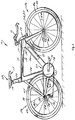
- Fig. 1 shows a bicycle 10 equipped with an internal bicycle battery assembly 27 that is constructed in accordance with the embodiments described herein.
- the internal bicycle battery assembly 27 can be used to provide power to a motor (not shown) or other component(s) to assist with propulsion of the bicycle 10.
- the bicycle 10 also includes a frame 13 to which a seat assembly 12 and handlebars 16 are attached.
- a seat clamp 14 is engaged with an underside 15 of seat assembly 12 and cooperates with a seat post 20 that slidably engages a seat tube 22 of frame 13.
- a top tube 24 and a down tube 26 extend forwardly from seat tube 22 to a head tube 28 of frame 13.
- the internal bicycle battery assembly 27 is incorporated into the down tube 26.
- the internal bicycle battery assembly could be incorporated into the top tube 24 or the seat tube 22.
- the internal bicycle battery assembly 27 is shown on a side of the down tube 26 in Fig. 1 for illustrative purposes. It is to be understood that the internal bicycle battery assembly 27 can alternatively be mounted to a top surface or a bottom surface of the down tube 26.
- Handlebars 16 are connected to a steerer tube 30 that passes through head tube 28 and engages a fork crown 32.
- a pair of forks 34, 35 extend from generally opposite ends of fork crown 32 and are constructed to support a front wheel assembly 36 at an end thereof or fork tip 38.
- Fork tips 38 engage generally opposite sides of an axle 40 that is constructed to engage a hub 42 of front wheel assembly 36.
- a number of spokes 44 extend from hub 42 to a rim 46 of front wheel assembly 36.
- a tire 48 is engaged with rim 46 such that rotation of tire 48, relative to forks 34, rotates rim 46 and hub 42.
- a rear wheel assembly 56 is positioned generally concentrically about a rear axle 64.
- Crankset 68 includes pedals 70 that are operationally connected to a flexible drive such as a chain 72 via a chain ring or sprocket 74.
- Rotation of chain 72 communicates a drive force to a rear section 76 of bicycle 10 having a gear cluster 78 positioned thereat.
- Gear cluster 78 is generally concentrically orientated with respect to rear axle 64 and includes a number of variable diameter gears.
- Gear cluster 78 is operationally connected to a hub 80 associated with a rear tire 69 of rear wheel assembly 56.
- a number of spokes 82 extend radially between hub 80 and a rim 81 that supports tire 69 of rear wheel assembly 56.
- rider operation of pedals 70 drives chain 72 thereby driving rear tire 69 which in turn propels bicycle 10.
- the internal bicycle battery assembly 27 supports a battery which provides pedal-assist and/or on-demand power functionalities.
- bicycle 10 could be provided in either of a road bicycle, mountain bicycle, off-road bicycle, trail bicycle, etc. configuration. It is appreciated that each configuration includes features generally directed to the intended operating environment of the bicycle.
- trail bicycles generally include more robust suspension and tire systems than road bicycles.
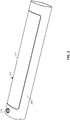
- Fig. 2 depicts a portion of a down tube 200 that includes an internal bicycle battery assembly (or battery assembly) 205 in accordance with an illustrative embodiment.
- the internal bicycle battery assembly 205 is mounted on a top surface of the down tube 200.
- the battery assembly 205 may be mounted on a side or bottom of the down tube 200.
- the battery assembly 205 may be mounted to a different portion of the bicycle frame.
- a key receptacle 210 is also incorporated into the down tube 200.
- the key receptacle 210 is configured to receive a key that disengages a battery lock and allows a user to remove the battery assembly 205 for convenient battery charging and/or replacement.
- the battery lock is described in more detail below.
- the key receptacle 210 can also be configured to receive a charging cord such that a battery of the battery assembly 205 can be charged while the battery assembly 205 is mounted to the down tube 200.
- a separate charging port may be included on the down tube 200 or the battery assembly 205.
- a cover plate 215 forms an external surface of the battery assembly 205.
- the cover plate 215 can be made from the same material as the down tube 205 and can have the same appearance (i.e., color, shape, gloss, graphics, etc.) as the down tube 205.
- Example materials can include carbon fiber, aluminum, plastic, and stainless steel.
- the cover plate 215 may be made from a different material and/or have a different appearance relative to the down tube 200.
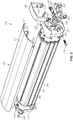
- Fig. 3 is an exploded view of a battery assembly 300 in accordance with an illustrative embodiment.
- the battery assembly 300 includes a battery 305, a cover plate assembly 310, a battery outlet cover 315, a front battery cover 320, a handle mount 325, and a handle 330.
- the battery assembly 300 may include fewer, additional, and/or different components.
- the battery 305 can be a lithium-ion battery or any other type of battery known in the art.
- the battery 305 is used to provide power to one or more components that enable pedal assist and/or on-demand power for the bicycle.
- the one or more components that receive power from the battery 305 can include one or more hub motors or any other type of electric motor(s) known in the art.
- the battery 305 can be connected to the one or more hub motors, etc. using wiring as known in the art.
- the cover plate assembly 310 is used to help secure and protect the battery 305 within a cavity of the down tube or other portion of the bicycle frame in which the battery assembly 300 is positioned.
- the cover plate assembly 310 includes a cover plate 311 and a side cover 312 for the battery 305.
- the cover plate 311 and the side cover 312 are integrally formed into a single component.
- the cover plate 311 and the side cover 312 can be distinct components which may be connected to one another via adhesive, fasteners, etc.
- the cover plate 311 and the side cover 312 can be distinct components which are independently mounted.
- the cover plate 311 can be made from the same material as the bicycle frame and can have the same appearance as the frame.
- the side cover 312 includes tracks 313 that are designed to fit within respective grooves on each side of a housing of the battery 305. As depicted in Fig. 3 , each side of the battery housing includes a first groove 306 and a second groove 307 such that the battery 305 includes two pairs of grooves. In alternative embodiments, a single pair of grooves may be used.
- the tracks 313 of the side cover 312 are designed to fit within the first groove 306 (or the second groove 307) on each side of the battery 305 such that the cover plate assembly 310 is secured to the battery 305, which in turn is secured to the bicycle frame as discussed below.
- the cover plate assembly 310 can also be attached to the battery 305 using fasteners, an adhesive, etc.
- Fig. 4 is a perspective view of the cover plate assembly 310 in accordance with an illustrative embodiment.
- the battery outlet cover 315 is used to secure a rear portion of the battery 305 (i.e., the portion of the battery 305 closest to a rear tire of the bicycle) to the bicycle frame.
- the battery outlet cover 315 is mounted to the battery 305 using fasteners 316, which can be screws, bolts, etc. Any number of the fasteners 316 may be used.
- the battery outlet cover 315 may be secured to the battery 305 by an adhesive or other method.
- the battery outlet cover 315 is secured to the bicycle frame by way of an outlet cover mounting bracket.
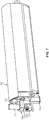
- Fig. 5 depicts the battery outlet cover 315 attached to an outlet cover mounting bracket 500 in accordance with an illustrative embodiment.
- the outlet cover mounting bracket 500 can be secured within the cavity of the down tube or other frame component in which the battery assembly is mounted.
- the outlet cover mounting bracket 500 can be secured to the frame using one or more fasteners, an adhesive, solder/weld, etc. depending on the frame material.
- Electrical wires (not shown) that connect the battery 305 to one or more motors can run through the battery outlet cover 315 and can be connected to the battery terminals as known in the art.
- the battery outlet cover 315 detaches from the outlet cover mounting bracket 500 upon removal of the battery assembly 300 from the bicycle. Removal of the battery assembly is depicted and described with reference to Figs. 9-14 .
- the front battery cover 320 is mounted to a front portion of the battery 305 (i.e., a portion of the battery 305 positioned closest to the front wheel of the bicycle) to help protect the battery 305 and to provide a mount for the handle 330.
- the front battery cover 320 is mounted to the battery 305 using fasteners 321.
- the front battery cover 320 may be mounted to the battery 305 using an adhesive, solder, weld, or other method.
- the front battery cover 320 includes mounting pedestals 322 that are used to secure the handle mount 325 to which the handle 330 is mounted.
- the mounting pedestals 322 on the front battery cover 320 include openings that are configured to receive bushings 323 and fasteners 324 such that the handle mount 325 is pivotally mounted to the front battery cover 320.
- the handle 330 for the battery assembly 300 is mounted to the handle mount 325 via the same fasteners 324 used to secure the handle mount 325 to the front battery cover 320. Additionally, the handle 330 includes protrusions 331 which are configured to mate with indentations 332 on the handle mount 325. As a result, the handle 330 is secured to the handle mount 325 and is unable to pivot independent of the handle mount 325.
- the front battery cover 320 also includes an opening 326 that is configured to receive a spring-loaded handle plunger 327, which is described in more detail below.
- the battery 305 can include an opening that aligns with the opening 326 such that the handle plunger 327 is at least partially recessed within the battery 305.
- Fig. 6 is a partial exploded view of the front portion of a battery assembly 600 in accordance with an illustrative embodiment.
- the battery assembly 600 includes a battery 605, a cover plate assembly 610, a front battery cover 615, a handle mount 620, and a handle 625.
- the front battery cover 615 includes an opening 616 that is aligned with an opening 617 in the battery 605.
- the openings 616 and 617 are configured to receive a handle plunger 630 and a spring 635 such that the handle plunger 630 is spring-loaded.
- the handle mount 620 when a battery lock for the battery assembly 600 is in a locked position, the handle mount 620 is pressed against the front battery cover 615, causing the spring 635 to compress such that the handle plunger 630 is in a spring-loaded position.
- the spring 635 Upon release of the battery lock, the spring 635 at least partially decompresses, causing the handle plunger 630 to push the handle mount 620 and the handle 625 mounted thereto away from the front face of the battery 605.
- Fig. 7 depicts a battery lock 700 engaged with a battery assembly 705 in accordance with an illustrative embodiment.
- Fig. 8 is a perspective view of the battery lock 700 in accordance with an illustrative embodiment.
- the battery lock 700 includes a base 710, a body 712, a key receptacle 715, a movable latch 720, and a stationary latch 725.
- the base 710 is mounted within the cavity of the bicycle frame that houses the battery assembly 705, and is used to mount the battery lock 700 to the frame.
- the base 710 can be mounted to the frame using solder, a weld, an adhesive, and/or one or more fasteners.
- the base 710 also includes an opening that houses a spring-loaded lock plunger 730.
- the battery lock 700 is in a locked position and a spring of the lock plunger 730 is compressed.
- the lock plunger 730 presses against a bottom side of a handle mount 735 such that the handle mount 735 is positioned between the lock plunger 730 and the movable latch 720.
- the handle mount 735 can be the same as or similar to the handle mounts 325 and 620 depicted in Figs. 3 and 6 , respectively.
- the key receptacle 715 is configured to receive a physical key which can be used to disengage the movable latch 720.
- the key receptacle 715 can be configured to receive an electronic signal from a user device that causes the movable latch 720 to disengage.
- the movable latch 720 is disengaged via a key, signal, etc.
- the movable latch 720 is drawn into the body 712 of the battery lock 700.
- the lock plunger 730 causes the battery assembly 705 to move outward from the cavity in which it is housed.
- the handle plunger 327 depicted in Fig. 3 (or the handle plunger 630 depicted in Fig.
- This two-stage locking mechanism prevents the battery assembly 705 from completely disengaging upon activation of the key, which helps prevent the battery assembly from ejecting off of the bicycle frame and falling to the ground upon key activation.
- Fig. 9 is a partial exterior view of the battery assembly 705 in a locked position in accordance with an illustrative embodiment. Visible in Fig. 9 is a cover plate assembly 900 of the battery assembly 705 that is flush with an exterior surface of a component 905 of a bicycle frame.
- the component 905 of the bicycle frame can be a down tube or any other frame component.
- the battery assembly 705 is secured within a cavity of the component 905 of the bicycle frame as depicted and described herein.
- the key receptacle 715 for the battery lock 700 is also depicted in Fig. 9 .
- Fig. 10 is a partial interior side view of the battery lock 700 in a locked position in accordance with an illustrative embodiment.
- the lock plunger 730 presses against the handle mount 735 and secures the handle mount 735 between the lock plunger 730 and the movable latch 720.
- a key 1000 is shown inserted into the key receptacle 715 in Fig. 10 .
- the key 1000 has not been activated (e.g., turned) and the movable latch 720 is depicted in the engaged (or locked) position.
- the key receptacle can be positioned and/or oriented in a different position on the frame.
- the key receptacle can also be positioned in a different location relative to the battery assembly.
- Fig. 11 is a partial interior side view of the battery lock 700 in an unlocked position in accordance with an illustrative embodiment.
- the key 1000 has been activated by a user, thereby causing the movable latch 720 to be withdrawn into the body 712 of the battery lock 700.
- the lock plunger 730 causes the battery assembly to move partially out of the cavity in which it is mounted.
- the handle plunger 327 depicted in Fig. 3 (or the handle plunger 630 depicted in Fig. 6 ) pushes on the handle mount 735 and causes the handle mount 735 to pivot away from the front face of the battery such that the handle mount 735 engages the stationary latch 725.
- the battery assembly is therefore partially disengaged from the bicycle frame, but is unable to be ejected and fall to the ground because of the stationary latch 725. More specifically, forces from the lock plunger 730 and the handle plunger 327 (or the handle plunger 630) cause the handle mount 735 to engage the stationary latch 725 once the user activates the key to the battery lock 700.
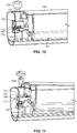
- Fig. 12 is a partial interior side view of the battery assembly 705 being disengaged from the battery lock 700 in accordance with an illustrative embodiment.
- a user presses a handle 1200 of the battery assembly 705 toward the front face of the battery, which causes the handle plunger 327 depicted in Fig. 3 (or the handle plunger 630 depicted in Fig. 6 ) to be compressed.
- the handle mount 735 which is mounted to the handle 1200, disengages from the stationary latch 725 such that the battery assembly 705 can be removed from the cavity in the bicycle frame.
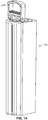
- Fig. 13 depicts removal of the battery assembly 705 from the cavity in the bicycle frame in accordance with an illustrative embodiment.
- Fig. 14 depicts the handle 1200 in a carry position in accordance with an illustrative embodiment.
- the handle 1200 allows a user to easily carry the battery assembly to a secure location for storage and/or charging.
- Fig. 15A depicts a battery assembly 1500 that includes a storage compartment 1505 in accordance with an illustrative embodiment.
- Fig. 15B depicts the storage compartment 1505 removed from the battery assembly 1500 in accordance with an illustrative embodiment.
- the storage compartment 1505 can be used to store a charging cable for the battery assembly 1500, a spare inner tube, one or more bicycle tools, personal items, etc.
- the storage compartment 1505 is fitted within a chamber 1510 formed into the battery assembly.
- the chamber 1510 is depicted as being adjacent to an end of the battery assembly 1500 that includes the handle such that the storage compartment 1505 does not interfere with the wiring or electrical connections of the battery.
- the chamber 1510 may be positioned elsewhere within the battery assembly.
- the chamber 1510 includes a slot 1515 that is configured to receive a protrusion 1520 on the storage compartment 1505 such that the storage compartment 1505 is securely mounted to the battery assembly 1500.
- a user can depress a tab 1525 to disengage the protrusion 1520 from the slot 1515.
- any other mounting techniques may be used to removably mount the storage compartment 1505 to the battery assembly 1500.
- the storage compartment 1505 may be permanently mounted within the battery assembly 1500 such that it is not removable from the battery assembly 1500.
Landscapes
- Engineering & Computer Science (AREA)
- Chemical & Material Sciences (AREA)
- Mechanical Engineering (AREA)
- Chemical Kinetics & Catalysis (AREA)
- Electrochemistry (AREA)
- General Chemical & Material Sciences (AREA)
- Combustion & Propulsion (AREA)
- Transportation (AREA)
- Battery Mounting, Suspending (AREA)
Applications Claiming Priority (1)
| Application Number | Priority Date | Filing Date | Title |
|---|---|---|---|
| US201862667840P | 2018-05-07 | 2018-05-07 |
Publications (2)
| Publication Number | Publication Date |
|---|---|
| EP3566940A1 true EP3566940A1 (de) | 2019-11-13 |
| EP3566940B1 EP3566940B1 (de) | 2023-08-16 |
Family
ID=66379835
Family Applications (1)
| Application Number | Title | Priority Date | Filing Date |
|---|---|---|---|
| EP19172366.7A Active EP3566940B1 (de) | 2018-05-07 | 2019-05-02 | Fahrradbatterieanordnung |
Country Status (4)
| Country | Link |
|---|---|
| US (1) | US11572132B2 (de) |
| EP (1) | EP3566940B1 (de) |
| ES (1) | ES2957311T3 (de) |
| PL (1) | PL3566940T3 (de) |
Cited By (2)
| Publication number | Priority date | Publication date | Assignee | Title |
|---|---|---|---|---|
| EP3771627A1 (de) * | 2019-08-01 | 2021-02-03 | Amprio GmbH | Elektrofahrrad- akkuhalterungsensemble |
| WO2024009167A1 (de) * | 2022-07-08 | 2024-01-11 | Mystromer Ag | Vorrichtung und verfahren zur ver- und entriegelung |
Families Citing this family (14)
| Publication number | Priority date | Publication date | Assignee | Title |
|---|---|---|---|---|
| WO2018185062A1 (en) * | 2017-04-04 | 2018-10-11 | Matsuura Frontini Matteo Giuseppe | Modular electric bicycle |
| DE102019204572B3 (de) * | 2019-04-01 | 2020-08-06 | Brose Antriebstechnik GmbH & Co. Kommanditgesellschaft, Berlin | Verriegelungseinrichtung zur Verriegelung einer Energieversorgungseinheit für ein Fahrrad |
| CN111816807B (zh) * | 2020-06-29 | 2023-11-28 | 长兴德威波尔能源科技有限公司 | 一种电动自行车电池组的结构及其组装方法 |
| US11945316B2 (en) * | 2020-06-30 | 2024-04-02 | Lyft, Inc. | Micromobility transit vehicle battery connection and lock systems and methods |
| JP7554596B2 (ja) * | 2020-07-31 | 2024-09-20 | 株式会社シマノ | 人力駆動車用のバッテリ保持装置、人力駆動車用のドライブユニット、および、人力駆動車用のバッテリユニット |
| DE202020104966U1 (de) * | 2020-08-27 | 2021-11-30 | Canyon Bicycles Gmbh | Batterieeinheit sowie Fahrradrahmen |
| KR20220042693A (ko) * | 2020-09-28 | 2022-04-05 | 현대자동차주식회사 | 퍼스널 모빌리티의 견인모듈 및 이를 포함하는 퍼스널 모빌리티, 퍼스널 모빌리티의 제어방법 |
| DE112021006208T5 (de) * | 2020-11-30 | 2023-09-14 | Panasonic Intellectual Property Management Co., Ltd. | Haltevorrichtung, Batterie, Batteriehaltemechanismus und Elektrofahrrad |
| US11565769B2 (en) | 2020-12-11 | 2023-01-31 | Specialized Bicycle Components, Inc. | 3-position battery latching system |
| DE102021107271A1 (de) | 2021-03-23 | 2022-09-29 | Iko Sportartikel-Handels-Gmbh | Befestigungsvorrichtung, Fahrzeugrohr, Akkubaugruppe sowie Fahrzeug |
| CN113335427B (zh) * | 2021-07-22 | 2022-07-08 | 深圳市海川伟业科技有限公司 | 一种便于收纳的电动自行车 |
| DE202021104617U1 (de) * | 2021-08-27 | 2022-11-29 | Canyon Bicycles Gmbh | Fahrradrahmenelement |
| US11884315B1 (en) * | 2021-09-30 | 2024-01-30 | Amazon Technologies, Inc. | Item identifying mobile apparatus |
| CN114348158B (zh) * | 2021-12-31 | 2023-05-30 | 浙江联宜电机有限公司 | 一种代步车 |
Citations (6)
| Publication number | Priority date | Publication date | Assignee | Title |
|---|---|---|---|---|
| JPH10181651A (ja) * | 1996-12-26 | 1998-07-07 | Yamaha Motor Co Ltd | 電動自転車のバッテリボックス固定構造 |
| JPH11105759A (ja) * | 1997-10-02 | 1999-04-20 | Mitsubishi Heavy Ind Ltd | 電動アシスト自転車 |
| JP3683307B2 (ja) * | 1995-06-30 | 2005-08-17 | ヤマハ発動機株式会社 | 車両用バッテリ収納装置 |
| DE202016104142U1 (de) * | 2016-07-28 | 2016-09-09 | Robert Bosch Gmbh | Halteelement zur Verwendung an einem Akkumulator sowie zugehörige Haltevorrichtung |
| DE202016104156U1 (de) * | 2016-07-28 | 2016-09-09 | Robert Bosch Gmbh | Vorrichtung zur Sicherung der Entnahme eines Akkumulators |
| US20180006278A1 (en) * | 2016-06-30 | 2018-01-04 | Shimano Inc. | Battery holder, battery unit, and battery component including battery holder and battery unit |
Family Cites Families (84)
| Publication number | Priority date | Publication date | Assignee | Title |
|---|---|---|---|---|
| DE69231799T2 (de) | 1991-06-04 | 2001-08-09 | Yamaha Hatsudoki K.K., Iwata | Muskelgetriebenes Fahrzeug |
| US5370200A (en) | 1992-05-11 | 1994-12-06 | Yamaha Hatsudoki Kabushiki Kaisha | Bicycle with electric motor |
| JP2623419B2 (ja) | 1992-09-30 | 1997-06-25 | ヤマハ発動機株式会社 | 電動モータ付き自転車 |
| JP3377258B2 (ja) | 1993-07-23 | 2003-02-17 | ヤマハ発動機株式会社 | 電動モータ付き乗り物 |
| JP2506047B2 (ja) | 1993-07-26 | 1996-06-12 | ヤマハ発動機株式会社 | 電動自転車 |
| US5368122A (en) | 1993-12-21 | 1994-11-29 | Chou; Wen-Cheng | Electrical bicycle |
| JP3231549B2 (ja) | 1994-06-11 | 2001-11-26 | 本田技研工業株式会社 | 電動補助自転車の充電コネクター配置構造 |
| JP3231551B2 (ja) | 1994-06-11 | 2001-11-26 | 本田技研工業株式会社 | 電動補助自転車のバッテリ着脱構造 |
| JP3056640B2 (ja) | 1994-06-11 | 2000-06-26 | 本田技研工業株式会社 | 電動補助自転車の電源用バッテリ収納構造 |
| JP3231550B2 (ja) | 1994-06-11 | 2001-11-26 | 本田技研工業株式会社 | 電動補助自転車のボデイカバー構造 |
| JPH07329858A (ja) | 1994-06-11 | 1995-12-19 | Honda Motor Co Ltd | 電動補助自転車のバッテリ着脱構造 |
| ES2134988T3 (es) | 1994-12-07 | 1999-10-16 | Honda Motor Co Ltd | Estructura de montaje para caja de bateria para una motocicleta. |
| JP3491708B2 (ja) | 1995-02-23 | 2004-01-26 | ヤマハ発動機株式会社 | 電動自転車用バッテリ収納装置 |
| US5749429A (en) | 1995-04-03 | 1998-05-12 | Suzuki Kabushiki Kaisha | Power assist apparatus of power assisted bicycle |
| JP3231991B2 (ja) | 1996-03-08 | 2001-11-26 | 本田技研工業株式会社 | 電動補助自転車用バッテリ |
| US5798702A (en) | 1996-04-18 | 1998-08-25 | Suzuki Motor Corporation | Residual battery capacity display device for electric vehicle |
| EP0820925A1 (de) | 1996-07-22 | 1998-01-28 | Merida Industry Co., Ltd. | Elektrischer Antrieb für ein Fahrrad |
| EP0832816A1 (de) | 1996-09-26 | 1998-04-01 | Mitsubishi Heavy Industries, Ltd. | Antriebseinheit für Fahrräder mit elektrischem Antrieb |
| JP2000238675A (ja) | 1999-02-23 | 2000-09-05 | Yamaha Motor Co Ltd | 電動自転車 |
| TW558537B (en) | 2000-09-15 | 2003-10-21 | Campagnolo Srl | Integrated control and power unit for use aboard a bicycle |
| US6920953B2 (en) | 2002-05-24 | 2005-07-26 | Mcgovern James Robert | Electrically assisted pedaled vehicle |
| CN2605187Y (zh) | 2003-02-13 | 2004-03-03 | 苏州工业园区诺亚科技有限公司 | 便携式电动车 |
| JP2005219728A (ja) | 2004-01-06 | 2005-08-18 | Land Walker Ltd | 自転車および自転車用の差動装置 |
| JP4456415B2 (ja) | 2004-06-07 | 2010-04-28 | ヤマハ発動機株式会社 | 荷重検出装置およびそれを用いた輸送機器 |
| JP3950875B2 (ja) | 2004-07-28 | 2007-08-01 | 株式会社シマノ | 自転車用電気配線支持構造 |
| US7243937B2 (en) | 2005-02-18 | 2007-07-17 | Shimano, Inc. | Bicycle control apparatus |
| JP4141453B2 (ja) | 2005-03-16 | 2008-08-27 | 株式会社シマノ | 自転車用電源装置 |
| JP2007015422A (ja) | 2005-07-05 | 2007-01-25 | Yamaha Motor Co Ltd | 電動自転車 |
| JP2007015641A (ja) | 2005-07-11 | 2007-01-25 | Yamaha Motor Co Ltd | 電動自転車 |
| US7547021B2 (en) | 2006-09-22 | 2009-06-16 | Nirve Sports, Ltd. | Propelled bicycle with automatic transmission |
| US7503547B2 (en) | 2006-10-04 | 2009-03-17 | Shimano Inc. | Bicycle electric cable tensioning assembly |
| DK176497B3 (da) | 2007-03-08 | 2018-06-18 | Protanium B V | Cykelstel med indbygget og aftageligt batteri |
| TWM316210U (en) | 2007-03-16 | 2007-08-01 | Ideal Bike Corp | Power apparatus for electric bicycle |
| CN100522733C (zh) | 2007-04-27 | 2009-08-05 | 崔晓宏 | 电动车架 |
| US8131413B2 (en) | 2007-09-25 | 2012-03-06 | Max Power Motors, Llc | Electric motor and conversion system for manually powered vehicles |
| US7604079B2 (en) | 2008-02-12 | 2009-10-20 | Jack Ray Pittman | Power drive for a bicycle |
| TW200951021A (en) | 2008-06-11 | 2009-12-16 | Chuan-Sheng Chen | Electric bicycle |
| US20100019676A1 (en) | 2008-07-28 | 2010-01-28 | Jen-Yen Yen | Electric generator for bicycle |
| DK2230164T3 (da) | 2009-03-20 | 2012-07-23 | Thoemus Veloshop Ag | Cykelstel til optagelse af en batterienhed og tilhørende batterienhed |
| WO2012066598A1 (ja) | 2010-11-18 | 2012-05-24 | 川崎重工業株式会社 | 電動二輪車 |
| US8789640B2 (en) | 2010-11-18 | 2014-07-29 | Kawasaki Jukogyo Kabushiki Kaisha | Electric motorcycle |
| DE102011079094A1 (de) | 2011-01-13 | 2012-07-19 | Johannes Biechele | Fahrradrahmen, Batteriepack und Fahrrad |
| CN202115671U (zh) | 2011-06-02 | 2012-01-18 | 宁波天邦实达工具有限公司 | 电动山地自行车 |
| EP2532571B1 (de) | 2011-06-10 | 2014-03-26 | Campagnolo S.r.l. | Am Fahrrad befestigte Vorrichtung und zugehöriges Montageverfahren |
| CN102420296B (zh) | 2011-10-21 | 2013-11-20 | 黄利明 | 电动自行车的电池盒 |
| CN202268414U (zh) | 2011-10-21 | 2012-06-06 | 黄利明 | 一种电动自行车的电池盒 |
| JP2013159194A (ja) | 2012-02-03 | 2013-08-19 | Shimano Inc | 電源部材、電源部材が挿入される筒状部材、および電源部材と筒状部材とを備える電源組立体 |
| CN202464076U (zh) | 2012-02-23 | 2012-10-03 | 佛山市三鹰进出口有限公司 | 一种隐藏式电池的电动自行车 |
| US8979110B2 (en) | 2012-03-16 | 2015-03-17 | Specialized Bicycle Components, Inc. | Bicycle with battery mount |
| US8727367B2 (en) * | 2012-03-16 | 2014-05-20 | Specialized Bicycle Components, Inc. | Bicycle with integrated cable routing |
| CN202624562U (zh) | 2012-04-25 | 2012-12-26 | 捷奥比电动车有限公司 | 电动自行车隐形电池安装结构 |
| CN102642593A (zh) | 2012-05-16 | 2012-08-22 | 苏州小蜻蜓电动车有限公司 | 一种电动自行车的电池盒结构 |
| CN202608942U (zh) | 2012-06-07 | 2012-12-19 | 太仓市哲泰天产品设计有限公司 | 一种电池防盗系统及采用该系统的电动自行车 |
| CN102700653A (zh) | 2012-06-07 | 2012-10-03 | 太仓市哲泰天产品设计有限公司 | 一种电池防盗系统及采用该系统的电动自行车 |
| KR101207885B1 (ko) | 2012-07-10 | 2012-12-20 | 주식회사 이알프스 | 전기자전거용 배터리의 장착장치 |
| CN102897261A (zh) | 2012-10-22 | 2013-01-30 | 浙江超级电气科技有限公司 | 一种用于电动自行车的车架结构 |
| CN202923825U (zh) | 2012-11-23 | 2013-05-08 | 深圳市喜德盛自行车有限公司 | 电动自行车用电源安装装置 |
| CN202923824U (zh) | 2012-11-23 | 2013-05-08 | 深圳市喜德盛自行车有限公司 | 电动自行车电源安装装置 |
| CN203064153U (zh) | 2012-12-19 | 2013-07-17 | 深圳市喜德盛自行车有限公司 | 电动自行车电池盒安装装置 |
| CN203071149U (zh) | 2012-12-19 | 2013-07-17 | 深圳市喜德盛自行车有限公司 | 电动自行车电池盒提手装置及安装装置 |
| CN103121486B (zh) | 2013-01-11 | 2015-10-21 | 苏州达方电子有限公司 | 电动自行车 |
| CN203020504U (zh) | 2013-01-15 | 2013-06-26 | 神州电动车有限公司 | 半隐藏于管内的电动自行车电池盒 |
| CN104118522B (zh) | 2013-04-27 | 2016-08-24 | 耀马车业(中国)有限公司 | 电动自行车用电池固定装置的改良结构 |
| CN203358801U (zh) | 2013-06-20 | 2013-12-25 | 谢晓斌 | 电动自行车及其电池装置 |
| KR101488841B1 (ko) | 2013-07-09 | 2015-02-04 | 주식회사 알톤스포츠 | 전기자전거용 배터리팩의 장착구조 |
| CN203553235U (zh) | 2013-10-22 | 2014-04-16 | 深圳市松吉电动自行车有限公司 | 电动自行车及其电池 |
| CN203652055U (zh) | 2013-11-14 | 2014-06-18 | 张克勇 | 电动自行车的蓄电池及电动自行车 |
| CN203681825U (zh) | 2014-01-08 | 2014-07-02 | 中山市电赢科技有限公司 | 一种电动自行车上电池组的侧滑安装结构 |
| JP6080779B2 (ja) | 2014-01-28 | 2017-02-15 | 株式会社シマノ | 自転車用電源ホルダ |
| CN203832691U (zh) | 2014-03-10 | 2014-09-17 | 久鼎金属实业股份有限公司 | 电动自行车的电池安装结构 |
| CN203921105U (zh) | 2014-05-30 | 2014-11-05 | 佛山市三鹰进出口有限公司 | 一种自行车电池盒的安装结构 |
| JP6167074B2 (ja) | 2014-07-31 | 2017-07-19 | ブリヂストンサイクル株式会社 | 自転車および自転車へのバッテリーの取り付け方法 |
| KR20160034711A (ko) | 2014-09-22 | 2016-03-30 | 한도에스티(주) | 전기자전거의 배터리 장착구조 |
| US10179626B2 (en) | 2014-12-15 | 2019-01-15 | Technologies Bewegan Inc. | Electric bicycle having integrated battery compartment |
| JP6367739B2 (ja) | 2015-02-27 | 2018-08-01 | 株式会社シマノ | 自転車用バッテリホルダ、自転車用バッテリ、および、自転車用バッテリの保持部材 |
| DE202015103750U1 (de) | 2015-07-16 | 2016-10-18 | Zeg Zweirad-Einkaufs-Genossenschaft Eg | Fahrradrahmen, Energieversorgungseinheit hierfür und Elektrofahrrad hiermit |
| CN205365968U (zh) | 2016-02-01 | 2016-07-06 | 刘怀禹 | 一种新型外露插接式电池盒 |
| DK178785B1 (da) * | 2016-02-29 | 2017-01-30 | Positive Energies Aps | Cykelstel med indbygget og aftageligt batteri |
| JP6599824B2 (ja) | 2016-06-29 | 2019-10-30 | 株式会社シマノ | 自転車用バッテリユニット |
| CN205737952U (zh) | 2016-06-30 | 2016-11-30 | 慈溪市惠业车辆配件工贸有限公司 | 一种电动自行车电源装置 |
| DE102016213903B3 (de) * | 2016-07-28 | 2018-01-11 | Robert Bosch Gmbh | Halteelement zur Verwendung an einem Akkumulator sowie zugehörige Haltevorrichtung |
| CN206327505U (zh) | 2016-10-13 | 2017-07-14 | 慈溪市惠业车辆配件工贸有限公司 | 一种电动自行车的隐藏式电池装置 |
| DE102018206821A1 (de) * | 2018-05-03 | 2019-11-07 | YT Industries GmbH | Set mit einer Akkueinheit und einer Aufnahmeeinrichtung zur Aufnahme der Akkueinheit |
| CN208882030U (zh) | 2018-08-15 | 2019-05-21 | 慈溪市普力为电动科技有限公司 | 一种带隐藏式手柄的电池盒的电动自行车电池装置 |
-
2019
- 2019-05-02 ES ES19172366T patent/ES2957311T3/es active Active
- 2019-05-02 EP EP19172366.7A patent/EP3566940B1/de active Active
- 2019-05-02 US US16/401,340 patent/US11572132B2/en active Active
- 2019-05-02 PL PL19172366.7T patent/PL3566940T3/pl unknown
Patent Citations (6)
| Publication number | Priority date | Publication date | Assignee | Title |
|---|---|---|---|---|
| JP3683307B2 (ja) * | 1995-06-30 | 2005-08-17 | ヤマハ発動機株式会社 | 車両用バッテリ収納装置 |
| JPH10181651A (ja) * | 1996-12-26 | 1998-07-07 | Yamaha Motor Co Ltd | 電動自転車のバッテリボックス固定構造 |
| JPH11105759A (ja) * | 1997-10-02 | 1999-04-20 | Mitsubishi Heavy Ind Ltd | 電動アシスト自転車 |
| US20180006278A1 (en) * | 2016-06-30 | 2018-01-04 | Shimano Inc. | Battery holder, battery unit, and battery component including battery holder and battery unit |
| DE202016104142U1 (de) * | 2016-07-28 | 2016-09-09 | Robert Bosch Gmbh | Halteelement zur Verwendung an einem Akkumulator sowie zugehörige Haltevorrichtung |
| DE202016104156U1 (de) * | 2016-07-28 | 2016-09-09 | Robert Bosch Gmbh | Vorrichtung zur Sicherung der Entnahme eines Akkumulators |
Cited By (3)
| Publication number | Priority date | Publication date | Assignee | Title |
|---|---|---|---|---|
| EP3771627A1 (de) * | 2019-08-01 | 2021-02-03 | Amprio GmbH | Elektrofahrrad- akkuhalterungsensemble |
| WO2024009167A1 (de) * | 2022-07-08 | 2024-01-11 | Mystromer Ag | Vorrichtung und verfahren zur ver- und entriegelung |
| CH719877A1 (de) * | 2022-07-08 | 2024-01-15 | Mystromer Ag | Vorrichtung und Verfahren zur Ver- und Entriegelung für ein elektrisch angetriebenes Fahrzeug. |
Also Published As
| Publication number | Publication date |
|---|---|
| EP3566940B1 (de) | 2023-08-16 |
| ES2957311T3 (es) | 2024-01-17 |
| US11572132B2 (en) | 2023-02-07 |
| US20190337587A1 (en) | 2019-11-07 |
| PL3566940T3 (pl) | 2024-01-03 |
Similar Documents
| Publication | Publication Date | Title |
|---|---|---|
| EP3566940B1 (de) | Fahrradbatterieanordnung | |
| US11581606B2 (en) | Bicycle battery storage system | |
| US7185726B2 (en) | Bicycle with optional power assist | |
| EP2423096A2 (de) | Fahrrad | |
| EP2855250B1 (de) | Elektromotorunterstütztes fahrrad sowie systeme und komponenten davon | |
| EP0822134B1 (de) | Verriegelungsmechanismus zum Verriegeln eines Aufnahmeraumes für eine Batterie | |
| US9381973B2 (en) | Modular bicycle | |
| US20110240391A1 (en) | Electric Two-Wheeler | |
| EP1363830B1 (de) | Scooter | |
| EP2759465A1 (de) | Batterieanordnung und menschenbetriebenes Fahrzeug damit | |
| JP6908557B2 (ja) | ロック装置、バッテリユニット、および、バッテリホルダ | |
| WO2017009637A1 (en) | Electric cycle | |
| JP2021193028A (ja) | ロック装置、および、バッテリホルダ | |
| CN117396357A (zh) | 包括可取出的可充电电池以及电池锁定装置的电动或混合动力可骑乘鞍式车辆 | |
| JP7092933B2 (ja) | 人力駆動車用のロックシステム | |
| US20160251052A1 (en) | Bicycle with detachable head-tube subassembly | |
| CN1282582C (zh) | 电动辅助自行车 | |
| US20240217611A1 (en) | An electric or hybrid rideable saddle vehicle comprising a rechargeable battery and a storage container | |
| JP3490900B2 (ja) | 電動自転車 | |
| JP2003182668A (ja) | 電動補助自転車 | |
| US7938421B2 (en) | Collapsible axle for velocipede | |
| WO2019155482A1 (en) | A locking system for battery pack in electric vehicles | |
| WO2011121122A1 (fr) | Vehicule a assistance electrique avec garde boue | |
| CN2258358Y (zh) | 可骑旅行箱 | |
| JP2002127967A (ja) | 電動自転車 |
Legal Events
| Date | Code | Title | Description |
|---|---|---|---|
| PUAI | Public reference made under article 153(3) epc to a published international application that has entered the european phase |
Free format text: ORIGINAL CODE: 0009012 |
|
| STAA | Information on the status of an ep patent application or granted ep patent |
Free format text: STATUS: THE APPLICATION HAS BEEN PUBLISHED |
|
| AK | Designated contracting states |
Kind code of ref document: A1 Designated state(s): AL AT BE BG CH CY CZ DE DK EE ES FI FR GB GR HR HU IE IS IT LI LT LU LV MC MK MT NL NO PL PT RO RS SE SI SK SM TR |
|
| AX | Request for extension of the european patent |
Extension state: BA ME |
|
| STAA | Information on the status of an ep patent application or granted ep patent |
Free format text: STATUS: REQUEST FOR EXAMINATION WAS MADE |
|
| 17P | Request for examination filed |
Effective date: 20200513 |
|
| RBV | Designated contracting states (corrected) |
Designated state(s): AL AT BE BG CH CY CZ DE DK EE ES FI FR GB GR HR HU IE IS IT LI LT LU LV MC MK MT NL NO PL PT RO RS SE SI SK SM TR |
|
| RIC1 | Information provided on ipc code assigned before grant |
Ipc: B62K 19/30 20060101ALI20200923BHEP Ipc: B62M 6/90 20100101ALI20200923BHEP Ipc: B62J 43/13 20200101AFI20200923BHEP Ipc: B62J 43/23 20200101ALN20200923BHEP Ipc: B62J 43/28 20200101ALI20200923BHEP Ipc: B62H 5/00 20060101ALI20200923BHEP |
|
| GRAP | Despatch of communication of intention to grant a patent |
Free format text: ORIGINAL CODE: EPIDOSNIGR1 |
|
| STAA | Information on the status of an ep patent application or granted ep patent |
Free format text: STATUS: GRANT OF PATENT IS INTENDED |
|
| INTG | Intention to grant announced |
Effective date: 20201111 |
|
| RIC1 | Information provided on ipc code assigned before grant |
Ipc: B62J 43/13 20200101AFI20201103BHEP Ipc: B62M 6/90 20100101ALI20201103BHEP Ipc: B62J 43/23 20200101ALN20201103BHEP Ipc: B62K 19/30 20060101ALI20201103BHEP Ipc: B62J 43/28 20200101ALI20201103BHEP Ipc: B62H 5/00 20060101ALI20201103BHEP |
|
| GRAJ | Information related to disapproval of communication of intention to grant by the applicant or resumption of examination proceedings by the epo deleted |
Free format text: ORIGINAL CODE: EPIDOSDIGR1 |
|
| STAA | Information on the status of an ep patent application or granted ep patent |
Free format text: STATUS: REQUEST FOR EXAMINATION WAS MADE |
|
| STAA | Information on the status of an ep patent application or granted ep patent |
Free format text: STATUS: EXAMINATION IS IN PROGRESS |
|
| INTC | Intention to grant announced (deleted) | ||
| 17Q | First examination report despatched |
Effective date: 20210329 |
|
| REG | Reference to a national code |
Ref country code: DE Ref legal event code: R079 Ref document number: 602019034947 Country of ref document: DE Free format text: PREVIOUS MAIN CLASS: B62M0006900000 Ipc: B62J0043130000 Ref country code: DE Ref legal event code: R079 Free format text: PREVIOUS MAIN CLASS: B62M0006900000 Ipc: B62J0043130000 |
|
| RIC1 | Information provided on ipc code assigned before grant |
Ipc: B62J 43/23 20200101ALN20230124BHEP Ipc: H01M 50/271 20210101ALI20230124BHEP Ipc: H01M 50/262 20210101ALI20230124BHEP Ipc: B62H 5/00 20060101ALI20230124BHEP Ipc: B62K 19/30 20060101ALI20230124BHEP Ipc: B62M 6/90 20100101ALI20230124BHEP Ipc: B62J 43/28 20200101ALI20230124BHEP Ipc: B62J 43/13 20200101AFI20230124BHEP |
|
| GRAP | Despatch of communication of intention to grant a patent |
Free format text: ORIGINAL CODE: EPIDOSNIGR1 |
|
| STAA | Information on the status of an ep patent application or granted ep patent |
Free format text: STATUS: GRANT OF PATENT IS INTENDED |
|
| RIC1 | Information provided on ipc code assigned before grant |
Ipc: B62J 43/23 20200101ALN20230213BHEP Ipc: H01M 50/271 20210101ALI20230213BHEP Ipc: H01M 50/262 20210101ALI20230213BHEP Ipc: B62H 5/00 20060101ALI20230213BHEP Ipc: B62K 19/30 20060101ALI20230213BHEP Ipc: B62M 6/90 20100101ALI20230213BHEP Ipc: B62J 43/28 20200101ALI20230213BHEP Ipc: B62J 43/13 20200101AFI20230213BHEP |
|
| INTG | Intention to grant announced |
Effective date: 20230313 |
|
| GRAS | Grant fee paid |
Free format text: ORIGINAL CODE: EPIDOSNIGR3 |
|
| GRAA | (expected) grant |
Free format text: ORIGINAL CODE: 0009210 |
|
| STAA | Information on the status of an ep patent application or granted ep patent |
Free format text: STATUS: THE PATENT HAS BEEN GRANTED |
|
| P01 | Opt-out of the competence of the unified patent court (upc) registered |
Effective date: 20230613 |
|
| AK | Designated contracting states |
Kind code of ref document: B1 Designated state(s): AL AT BE BG CH CY CZ DE DK EE ES FI FR GB GR HR HU IE IS IT LI LT LU LV MC MK MT NL NO PL PT RO RS SE SI SK SM TR |
|
| REG | Reference to a national code |
Ref country code: CH Ref legal event code: EP Ref country code: DE Ref legal event code: R096 Ref document number: 602019034947 Country of ref document: DE |
|
| REG | Reference to a national code |
Ref country code: IE Ref legal event code: FG4D |
|
| REG | Reference to a national code |
Ref country code: NL Ref legal event code: FP |
|
| REG | Reference to a national code |
Ref country code: LT Ref legal event code: MG9D |
|
| REG | Reference to a national code |
Ref country code: AT Ref legal event code: MK05 Ref document number: 1599812 Country of ref document: AT Kind code of ref document: T Effective date: 20230816 |
|
| REG | Reference to a national code |
Ref country code: ES Ref legal event code: FG2A Ref document number: 2957311 Country of ref document: ES Kind code of ref document: T3 Effective date: 20240117 |
|
| PG25 | Lapsed in a contracting state [announced via postgrant information from national office to epo] |
Ref country code: GR Free format text: LAPSE BECAUSE OF FAILURE TO SUBMIT A TRANSLATION OF THE DESCRIPTION OR TO PAY THE FEE WITHIN THE PRESCRIBED TIME-LIMIT Effective date: 20231117 |
|
| PG25 | Lapsed in a contracting state [announced via postgrant information from national office to epo] |
Ref country code: IS Free format text: LAPSE BECAUSE OF FAILURE TO SUBMIT A TRANSLATION OF THE DESCRIPTION OR TO PAY THE FEE WITHIN THE PRESCRIBED TIME-LIMIT Effective date: 20231216 |
|
| PG25 | Lapsed in a contracting state [announced via postgrant information from national office to epo] |
Ref country code: SE Free format text: LAPSE BECAUSE OF FAILURE TO SUBMIT A TRANSLATION OF THE DESCRIPTION OR TO PAY THE FEE WITHIN THE PRESCRIBED TIME-LIMIT Effective date: 20230816 Ref country code: RS Free format text: LAPSE BECAUSE OF FAILURE TO SUBMIT A TRANSLATION OF THE DESCRIPTION OR TO PAY THE FEE WITHIN THE PRESCRIBED TIME-LIMIT Effective date: 20230816 Ref country code: PT Free format text: LAPSE BECAUSE OF FAILURE TO SUBMIT A TRANSLATION OF THE DESCRIPTION OR TO PAY THE FEE WITHIN THE PRESCRIBED TIME-LIMIT Effective date: 20231218 Ref country code: NO Free format text: LAPSE BECAUSE OF FAILURE TO SUBMIT A TRANSLATION OF THE DESCRIPTION OR TO PAY THE FEE WITHIN THE PRESCRIBED TIME-LIMIT Effective date: 20231116 Ref country code: LV Free format text: LAPSE BECAUSE OF FAILURE TO SUBMIT A TRANSLATION OF THE DESCRIPTION OR TO PAY THE FEE WITHIN THE PRESCRIBED TIME-LIMIT Effective date: 20230816 Ref country code: LT Free format text: LAPSE BECAUSE OF FAILURE TO SUBMIT A TRANSLATION OF THE DESCRIPTION OR TO PAY THE FEE WITHIN THE PRESCRIBED TIME-LIMIT Effective date: 20230816 Ref country code: IS Free format text: LAPSE BECAUSE OF FAILURE TO SUBMIT A TRANSLATION OF THE DESCRIPTION OR TO PAY THE FEE WITHIN THE PRESCRIBED TIME-LIMIT Effective date: 20231216 Ref country code: HR Free format text: LAPSE BECAUSE OF FAILURE TO SUBMIT A TRANSLATION OF THE DESCRIPTION OR TO PAY THE FEE WITHIN THE PRESCRIBED TIME-LIMIT Effective date: 20230816 Ref country code: GR Free format text: LAPSE BECAUSE OF FAILURE TO SUBMIT A TRANSLATION OF THE DESCRIPTION OR TO PAY THE FEE WITHIN THE PRESCRIBED TIME-LIMIT Effective date: 20231117 Ref country code: FI Free format text: LAPSE BECAUSE OF FAILURE TO SUBMIT A TRANSLATION OF THE DESCRIPTION OR TO PAY THE FEE WITHIN THE PRESCRIBED TIME-LIMIT Effective date: 20230816 Ref country code: AT Free format text: LAPSE BECAUSE OF FAILURE TO SUBMIT A TRANSLATION OF THE DESCRIPTION OR TO PAY THE FEE WITHIN THE PRESCRIBED TIME-LIMIT Effective date: 20230816 |
|
| PGFP | Annual fee paid to national office [announced via postgrant information from national office to epo] |
Ref country code: NL Payment date: 20240315 Year of fee payment: 6 |
|
| PG25 | Lapsed in a contracting state [announced via postgrant information from national office to epo] |
Ref country code: SM Free format text: LAPSE BECAUSE OF FAILURE TO SUBMIT A TRANSLATION OF THE DESCRIPTION OR TO PAY THE FEE WITHIN THE PRESCRIBED TIME-LIMIT Effective date: 20230816 Ref country code: RO Free format text: LAPSE BECAUSE OF FAILURE TO SUBMIT A TRANSLATION OF THE DESCRIPTION OR TO PAY THE FEE WITHIN THE PRESCRIBED TIME-LIMIT Effective date: 20230816 Ref country code: EE Free format text: LAPSE BECAUSE OF FAILURE TO SUBMIT A TRANSLATION OF THE DESCRIPTION OR TO PAY THE FEE WITHIN THE PRESCRIBED TIME-LIMIT Effective date: 20230816 Ref country code: DK Free format text: LAPSE BECAUSE OF FAILURE TO SUBMIT A TRANSLATION OF THE DESCRIPTION OR TO PAY THE FEE WITHIN THE PRESCRIBED TIME-LIMIT Effective date: 20230816 Ref country code: CZ Free format text: LAPSE BECAUSE OF FAILURE TO SUBMIT A TRANSLATION OF THE DESCRIPTION OR TO PAY THE FEE WITHIN THE PRESCRIBED TIME-LIMIT Effective date: 20230816 Ref country code: SK Free format text: LAPSE BECAUSE OF FAILURE TO SUBMIT A TRANSLATION OF THE DESCRIPTION OR TO PAY THE FEE WITHIN THE PRESCRIBED TIME-LIMIT Effective date: 20230816 |
|
| PGFP | Annual fee paid to national office [announced via postgrant information from national office to epo] |
Ref country code: GB Payment date: 20240314 Year of fee payment: 6 |
|
| REG | Reference to a national code |
Ref country code: DE Ref legal event code: R097 Ref document number: 602019034947 Country of ref document: DE |
|
| PLBE | No opposition filed within time limit |
Free format text: ORIGINAL CODE: 0009261 |
|
| STAA | Information on the status of an ep patent application or granted ep patent |
Free format text: STATUS: NO OPPOSITION FILED WITHIN TIME LIMIT |
|
| PGFP | Annual fee paid to national office [announced via postgrant information from national office to epo] |
Ref country code: DE Payment date: 20240306 Year of fee payment: 6 |
|
| PGFP | Annual fee paid to national office [announced via postgrant information from national office to epo] |
Ref country code: CH Payment date: 20240602 Year of fee payment: 6 |
|
| PGFP | Annual fee paid to national office [announced via postgrant information from national office to epo] |
Ref country code: ES Payment date: 20240613 Year of fee payment: 6 |
|
| 26N | No opposition filed |
Effective date: 20240517 |
|
| PG25 | Lapsed in a contracting state [announced via postgrant information from national office to epo] |
Ref country code: SI Free format text: LAPSE BECAUSE OF FAILURE TO SUBMIT A TRANSLATION OF THE DESCRIPTION OR TO PAY THE FEE WITHIN THE PRESCRIBED TIME-LIMIT Effective date: 20230816 |