EP3553299B1 - Motorsteuergerät und motorsteuerungsverfahren - Google Patents
Motorsteuergerät und motorsteuerungsverfahren Download PDFInfo
- Publication number
- EP3553299B1 EP3553299B1 EP19162470.9A EP19162470A EP3553299B1 EP 3553299 B1 EP3553299 B1 EP 3553299B1 EP 19162470 A EP19162470 A EP 19162470A EP 3553299 B1 EP3553299 B1 EP 3553299B1
- Authority
- EP
- European Patent Office
- Prior art keywords
- cylinder
- air
- fuel ratio
- correction
- fuel
- Prior art date
- Legal status (The legal status is an assumption and is not a legal conclusion. Google has not performed a legal analysis and makes no representation as to the accuracy of the status listed.)
- Active
Links
Images


Classifications
-
- F—MECHANICAL ENGINEERING; LIGHTING; HEATING; WEAPONS; BLASTING
- F02—COMBUSTION ENGINES; HOT-GAS OR COMBUSTION-PRODUCT ENGINE PLANTS
- F02D—CONTROLLING COMBUSTION ENGINES
- F02D41/00—Electrical control of supply of combustible mixture or its constituents
- F02D41/02—Circuit arrangements for generating control signals
- F02D41/04—Introducing corrections for particular operating conditions
- F02D41/06—Introducing corrections for particular operating conditions for engine starting or warming up
- F02D41/061—Introducing corrections for particular operating conditions for engine starting or warming up the corrections being time dependent
-
- F—MECHANICAL ENGINEERING; LIGHTING; HEATING; WEAPONS; BLASTING
- F02—COMBUSTION ENGINES; HOT-GAS OR COMBUSTION-PRODUCT ENGINE PLANTS
- F02D—CONTROLLING COMBUSTION ENGINES
- F02D37/00—Non-electrical conjoint control of two or more functions of engines, not otherwise provided for
- F02D37/02—Non-electrical conjoint control of two or more functions of engines, not otherwise provided for one of the functions being ignition
-
- F—MECHANICAL ENGINEERING; LIGHTING; HEATING; WEAPONS; BLASTING
- F02—COMBUSTION ENGINES; HOT-GAS OR COMBUSTION-PRODUCT ENGINE PLANTS
- F02D—CONTROLLING COMBUSTION ENGINES
- F02D41/00—Electrical control of supply of combustible mixture or its constituents
- F02D41/0025—Controlling engines characterised by use of non-liquid fuels, pluralities of fuels, or non-fuel substances added to the combustible mixtures
- F02D41/0047—Controlling exhaust gas recirculation [EGR]
- F02D41/005—Controlling exhaust gas recirculation [EGR] according to engine operating conditions
- F02D41/0052—Feedback control of engine parameters, e.g. for control of air/fuel ratio or intake air amount
-
- F—MECHANICAL ENGINEERING; LIGHTING; HEATING; WEAPONS; BLASTING
- F02—COMBUSTION ENGINES; HOT-GAS OR COMBUSTION-PRODUCT ENGINE PLANTS
- F02D—CONTROLLING COMBUSTION ENGINES
- F02D41/00—Electrical control of supply of combustible mixture or its constituents
- F02D41/008—Controlling each cylinder individually
-
- F—MECHANICAL ENGINEERING; LIGHTING; HEATING; WEAPONS; BLASTING
- F02—COMBUSTION ENGINES; HOT-GAS OR COMBUSTION-PRODUCT ENGINE PLANTS
- F02D—CONTROLLING COMBUSTION ENGINES
- F02D41/00—Electrical control of supply of combustible mixture or its constituents
- F02D41/008—Controlling each cylinder individually
- F02D41/0085—Balancing of cylinder outputs, e.g. speed, torque or air-fuel ratio
-
- F—MECHANICAL ENGINEERING; LIGHTING; HEATING; WEAPONS; BLASTING
- F02—COMBUSTION ENGINES; HOT-GAS OR COMBUSTION-PRODUCT ENGINE PLANTS
- F02D—CONTROLLING COMBUSTION ENGINES
- F02D41/00—Electrical control of supply of combustible mixture or its constituents
- F02D41/02—Circuit arrangements for generating control signals
- F02D41/021—Introducing corrections for particular conditions exterior to the engine
- F02D41/0235—Introducing corrections for particular conditions exterior to the engine in relation with the state of the exhaust gas treating apparatus
-
- F—MECHANICAL ENGINEERING; LIGHTING; HEATING; WEAPONS; BLASTING
- F02—COMBUSTION ENGINES; HOT-GAS OR COMBUSTION-PRODUCT ENGINE PLANTS
- F02D—CONTROLLING COMBUSTION ENGINES
- F02D41/00—Electrical control of supply of combustible mixture or its constituents
- F02D41/02—Circuit arrangements for generating control signals
- F02D41/021—Introducing corrections for particular conditions exterior to the engine
- F02D41/0235—Introducing corrections for particular conditions exterior to the engine in relation with the state of the exhaust gas treating apparatus
- F02D41/024—Introducing corrections for particular conditions exterior to the engine in relation with the state of the exhaust gas treating apparatus to increase temperature of the exhaust gas treating apparatus
- F02D41/0255—Introducing corrections for particular conditions exterior to the engine in relation with the state of the exhaust gas treating apparatus to increase temperature of the exhaust gas treating apparatus to accelerate the warming-up of the exhaust gas treating apparatus at engine start
-
- F—MECHANICAL ENGINEERING; LIGHTING; HEATING; WEAPONS; BLASTING
- F02—COMBUSTION ENGINES; HOT-GAS OR COMBUSTION-PRODUCT ENGINE PLANTS
- F02D—CONTROLLING COMBUSTION ENGINES
- F02D41/00—Electrical control of supply of combustible mixture or its constituents
- F02D41/02—Circuit arrangements for generating control signals
- F02D41/14—Introducing closed-loop corrections
- F02D41/1438—Introducing closed-loop corrections using means for determining characteristics of the combustion gases; Sensors therefor
- F02D41/1439—Introducing closed-loop corrections using means for determining characteristics of the combustion gases; Sensors therefor characterised by the position of the sensor
- F02D41/144—Sensor in intake manifold
-
- F—MECHANICAL ENGINEERING; LIGHTING; HEATING; WEAPONS; BLASTING
- F02—COMBUSTION ENGINES; HOT-GAS OR COMBUSTION-PRODUCT ENGINE PLANTS
- F02D—CONTROLLING COMBUSTION ENGINES
- F02D41/00—Electrical control of supply of combustible mixture or its constituents
- F02D41/02—Circuit arrangements for generating control signals
- F02D41/14—Introducing closed-loop corrections
- F02D41/1438—Introducing closed-loop corrections using means for determining characteristics of the combustion gases; Sensors therefor
- F02D41/1439—Introducing closed-loop corrections using means for determining characteristics of the combustion gases; Sensors therefor characterised by the position of the sensor
- F02D41/1441—Plural sensors
-
- F—MECHANICAL ENGINEERING; LIGHTING; HEATING; WEAPONS; BLASTING
- F02—COMBUSTION ENGINES; HOT-GAS OR COMBUSTION-PRODUCT ENGINE PLANTS
- F02D—CONTROLLING COMBUSTION ENGINES
- F02D41/00—Electrical control of supply of combustible mixture or its constituents
- F02D41/02—Circuit arrangements for generating control signals
- F02D41/14—Introducing closed-loop corrections
- F02D41/1438—Introducing closed-loop corrections using means for determining characteristics of the combustion gases; Sensors therefor
- F02D41/1444—Introducing closed-loop corrections using means for determining characteristics of the combustion gases; Sensors therefor characterised by the characteristics of the combustion gases
- F02D41/1454—Introducing closed-loop corrections using means for determining characteristics of the combustion gases; Sensors therefor characterised by the characteristics of the combustion gases the characteristics being an oxygen content or concentration or the air-fuel ratio
-
- F—MECHANICAL ENGINEERING; LIGHTING; HEATING; WEAPONS; BLASTING
- F02—COMBUSTION ENGINES; HOT-GAS OR COMBUSTION-PRODUCT ENGINE PLANTS
- F02D—CONTROLLING COMBUSTION ENGINES
- F02D41/00—Electrical control of supply of combustible mixture or its constituents
- F02D41/02—Circuit arrangements for generating control signals
- F02D41/14—Introducing closed-loop corrections
- F02D41/1438—Introducing closed-loop corrections using means for determining characteristics of the combustion gases; Sensors therefor
- F02D41/1473—Introducing closed-loop corrections using means for determining characteristics of the combustion gases; Sensors therefor characterised by the regulation method
- F02D41/1475—Regulating the air fuel ratio at a value other than stoichiometry
-
- F—MECHANICAL ENGINEERING; LIGHTING; HEATING; WEAPONS; BLASTING
- F02—COMBUSTION ENGINES; HOT-GAS OR COMBUSTION-PRODUCT ENGINE PLANTS
- F02D—CONTROLLING COMBUSTION ENGINES
- F02D41/00—Electrical control of supply of combustible mixture or its constituents
- F02D41/30—Controlling fuel injection
-
- F—MECHANICAL ENGINEERING; LIGHTING; HEATING; WEAPONS; BLASTING
- F02—COMBUSTION ENGINES; HOT-GAS OR COMBUSTION-PRODUCT ENGINE PLANTS
- F02D—CONTROLLING COMBUSTION ENGINES
- F02D41/00—Electrical control of supply of combustible mixture or its constituents
- F02D41/30—Controlling fuel injection
- F02D41/38—Controlling fuel injection of the high pressure type
- F02D41/40—Controlling fuel injection of the high pressure type with means for controlling injection timing or duration
-
- F—MECHANICAL ENGINEERING; LIGHTING; HEATING; WEAPONS; BLASTING
- F02—COMBUSTION ENGINES; HOT-GAS OR COMBUSTION-PRODUCT ENGINE PLANTS
- F02D—CONTROLLING COMBUSTION ENGINES
- F02D43/00—Conjoint electrical control of two or more functions, e.g. ignition, fuel-air mixture, recirculation, supercharging or exhaust-gas treatment
- F02D43/04—Conjoint electrical control of two or more functions, e.g. ignition, fuel-air mixture, recirculation, supercharging or exhaust-gas treatment using only digital means
-
- F—MECHANICAL ENGINEERING; LIGHTING; HEATING; WEAPONS; BLASTING
- F02—COMBUSTION ENGINES; HOT-GAS OR COMBUSTION-PRODUCT ENGINE PLANTS
- F02P—IGNITION, OTHER THAN COMPRESSION IGNITION, FOR INTERNAL-COMBUSTION ENGINES; TESTING OF IGNITION TIMING IN COMPRESSION-IGNITION ENGINES
- F02P5/00—Advancing or retarding ignition; Control therefor
- F02P5/04—Advancing or retarding ignition; Control therefor automatically, as a function of the working conditions of the engine or vehicle or of the atmospheric conditions
- F02P5/045—Advancing or retarding ignition; Control therefor automatically, as a function of the working conditions of the engine or vehicle or of the atmospheric conditions combined with electronic control of other engine functions, e.g. fuel injection
-
- F—MECHANICAL ENGINEERING; LIGHTING; HEATING; WEAPONS; BLASTING
- F02—COMBUSTION ENGINES; HOT-GAS OR COMBUSTION-PRODUCT ENGINE PLANTS
- F02P—IGNITION, OTHER THAN COMPRESSION IGNITION, FOR INTERNAL-COMBUSTION ENGINES; TESTING OF IGNITION TIMING IN COMPRESSION-IGNITION ENGINES
- F02P5/00—Advancing or retarding ignition; Control therefor
- F02P5/04—Advancing or retarding ignition; Control therefor automatically, as a function of the working conditions of the engine or vehicle or of the atmospheric conditions
- F02P5/145—Advancing or retarding ignition; Control therefor automatically, as a function of the working conditions of the engine or vehicle or of the atmospheric conditions using electrical means
- F02P5/15—Digital data processing
- F02P5/1502—Digital data processing using one central computing unit
- F02P5/1512—Digital data processing using one central computing unit with particular means concerning an individual cylinder
-
- F—MECHANICAL ENGINEERING; LIGHTING; HEATING; WEAPONS; BLASTING
- F02—COMBUSTION ENGINES; HOT-GAS OR COMBUSTION-PRODUCT ENGINE PLANTS
- F02P—IGNITION, OTHER THAN COMPRESSION IGNITION, FOR INTERNAL-COMBUSTION ENGINES; TESTING OF IGNITION TIMING IN COMPRESSION-IGNITION ENGINES
- F02P5/00—Advancing or retarding ignition; Control therefor
- F02P5/04—Advancing or retarding ignition; Control therefor automatically, as a function of the working conditions of the engine or vehicle or of the atmospheric conditions
- F02P5/145—Advancing or retarding ignition; Control therefor automatically, as a function of the working conditions of the engine or vehicle or of the atmospheric conditions using electrical means
- F02P5/15—Digital data processing
- F02P5/152—Digital data processing dependent on pinking
- F02P5/1522—Digital data processing dependent on pinking with particular means concerning an individual cylinder
-
- F—MECHANICAL ENGINEERING; LIGHTING; HEATING; WEAPONS; BLASTING
- F02—COMBUSTION ENGINES; HOT-GAS OR COMBUSTION-PRODUCT ENGINE PLANTS
- F02P—IGNITION, OTHER THAN COMPRESSION IGNITION, FOR INTERNAL-COMBUSTION ENGINES; TESTING OF IGNITION TIMING IN COMPRESSION-IGNITION ENGINES
- F02P9/00—Electric spark ignition control, not otherwise provided for
- F02P9/002—Control of spark intensity, intensifying, lengthening, suppression
-
- F—MECHANICAL ENGINEERING; LIGHTING; HEATING; WEAPONS; BLASTING
- F02—COMBUSTION ENGINES; HOT-GAS OR COMBUSTION-PRODUCT ENGINE PLANTS
- F02D—CONTROLLING COMBUSTION ENGINES
- F02D41/00—Electrical control of supply of combustible mixture or its constituents
- F02D41/02—Circuit arrangements for generating control signals
- F02D41/021—Introducing corrections for particular conditions exterior to the engine
- F02D41/0235—Introducing corrections for particular conditions exterior to the engine in relation with the state of the exhaust gas treating apparatus
- F02D2041/0265—Introducing corrections for particular conditions exterior to the engine in relation with the state of the exhaust gas treating apparatus to decrease temperature of the exhaust gas treating apparatus
-
- F—MECHANICAL ENGINEERING; LIGHTING; HEATING; WEAPONS; BLASTING
- F02—COMBUSTION ENGINES; HOT-GAS OR COMBUSTION-PRODUCT ENGINE PLANTS
- F02D—CONTROLLING COMBUSTION ENGINES
- F02D41/00—Electrical control of supply of combustible mixture or its constituents
- F02D41/02—Circuit arrangements for generating control signals
- F02D41/021—Introducing corrections for particular conditions exterior to the engine
- F02D41/0235—Introducing corrections for particular conditions exterior to the engine in relation with the state of the exhaust gas treating apparatus
- F02D41/024—Introducing corrections for particular conditions exterior to the engine in relation with the state of the exhaust gas treating apparatus to increase temperature of the exhaust gas treating apparatus
-
- F—MECHANICAL ENGINEERING; LIGHTING; HEATING; WEAPONS; BLASTING
- F02—COMBUSTION ENGINES; HOT-GAS OR COMBUSTION-PRODUCT ENGINE PLANTS
- F02P—IGNITION, OTHER THAN COMPRESSION IGNITION, FOR INTERNAL-COMBUSTION ENGINES; TESTING OF IGNITION TIMING IN COMPRESSION-IGNITION ENGINES
- F02P5/00—Advancing or retarding ignition; Control therefor
- F02P5/04—Advancing or retarding ignition; Control therefor automatically, as a function of the working conditions of the engine or vehicle or of the atmospheric conditions
- F02P5/145—Advancing or retarding ignition; Control therefor automatically, as a function of the working conditions of the engine or vehicle or of the atmospheric conditions using electrical means
- F02P5/15—Digital data processing
- F02P5/1502—Digital data processing using one central computing unit
- F02P5/151—Digital data processing using one central computing unit with means for compensating the variation of the characteristics of the engine or of a sensor, e.g. by ageing
-
- Y—GENERAL TAGGING OF NEW TECHNOLOGICAL DEVELOPMENTS; GENERAL TAGGING OF CROSS-SECTIONAL TECHNOLOGIES SPANNING OVER SEVERAL SECTIONS OF THE IPC; TECHNICAL SUBJECTS COVERED BY FORMER USPC CROSS-REFERENCE ART COLLECTIONS [XRACs] AND DIGESTS
- Y02—TECHNOLOGIES OR APPLICATIONS FOR MITIGATION OR ADAPTATION AGAINST CLIMATE CHANGE
- Y02T—CLIMATE CHANGE MITIGATION TECHNOLOGIES RELATED TO TRANSPORTATION
- Y02T10/00—Road transport of goods or passengers
- Y02T10/10—Internal combustion engine [ICE] based vehicles
- Y02T10/12—Improving ICE efficiencies
Definitions
- the following description relates to an engine controller and an engine controlling method configured to perform a cylinder-by-cylinder correction of a fuel injection amount so as to cause differences among air-fuel ratios of air-fuel mixture burned in multiple cylinders.
- a typical engine controller operates an engine while causing differences among the air-fuel ratios of air-fuel mixture burned in the cylinders through a cylinder-by-cylinder correction of the fuel injection amount.
- a typical engine controller is configured to compensate for steady air-fuel ratio deviations caused by fluctuations of the intensity of exhaust gas blow on the air-fuel sensor from the respective cylinders through a cylinder-by-cylinder correction of the fuel injection amount.
- the cylinder-by-cylinder correction of the fuel injection amount may be performed in order to suppress an excessive temperature rise of a catalyst device installed in the exhaust passage or to promote a temperature rise of the catalyst device.
- Patent document US 5 755 205 A discloses an engine control system in which an air fuel ratio is controlled to a lean value closer to a stable combustion limit than a theoretical air fuel ratio under a predetermined operating range, comprising base air fuel ratio control element for setting a target air fuel ratio close to the stable combustion limit and for setting a base air fuel ratio control gain so as to accomplish the target air fuel, a combustion condition judging element for judging a combustion condition of each of cylinders of the engine, air fuel ratio compensating element for compensating the air fuel control gain based on the combustion condition judging element and ignition timing control means for setting an ignition timing in accordance with the target air fuel ratio in the predetermined operating range and for compensating the ignition timing taking account of the compensation of the air fuel ratio by the air fuel ratio compensating element.
- an engine controller that includes a fuel injection corrector.
- the fuel injection corrector is configured to perform a cylinder-by-cylinder correction of a fuel injection amount so as to cause differences among air-fuel ratios of air-fuel mixture burned in a plurality of cylinders.
- the fuel injection corrector is configured to perform a cylinder-by-cylinder correction of ignition timing such that the ignition timing of the cylinder in which combustion is performed at the air-fuel ratio richer than the output air-fuel ratio becomes more advanced than the ignition timing of other cylinders.
- an engine controlling method includes: performing a cylinder-by-cylinder correction of a fuel injection amount so as to cause differences among air-fuel ratios of air-fuel mixture burned in a plurality of cylinders; and in a case in which the cylinder-by-cylinder correction of the fuel injection amount results in a cylinder in which combustion is performed at an air-fuel ratio richer than an output air-fuel ratio, which is an air-fuel ratio at which combustion torque is maximized, performing a cylinder-by-cylinder correction of ignition timing such that the ignition timing of the cylinder in which combustion is performed at the air-fuel ratio richer than the output air-fuel ratio becomes more advanced than the ignition timing of other cylinders.
- the above aspects provide an engine controller and an engine controlling method capable of limiting a decrease in engine output efficiency due to a cylinder-by-cylinder correction of fuel injection amount.
- the engine controller serves as a fuel injection controller (or, fuel injection corrector).
- an engine 10 is an inline four-cylinder engine, which includes inline four cylinders #1 to #4.
- the engine 10 includes an intake passage 11 provided with an air flow meter 12 and a throttle valve 13.
- the air flow meter 12 detects the flow rate of intake air (intake air amount) flowing through the intake passage 11.
- the throttle valve 13 adjusts an intake air amount GA of the intake passage 11.
- the intake passage 11 is connected to an intake manifold 14 on the downstream side of the throttle valve 13.
- the intake manifold 14 is a branched tube for diverting the intake air for the respective cylinders.
- the engine 10 includes fuel injection valves 15 for injecting fuel into intake air diverted for the respective cylinder by the intake manifold 14.
- Each of the cylinders #1 to #4 is provided with a fuel injection valve 15 and an ignition plug 16.
- the ignition plug 16 ignites, with spark discharge, air-fuel mixture of the intake air drawn in through the intake passage 11 and the fuel injected by the fuel injection valve 15.
- the engine 10 is provided with an exhaust passage 17 having an exhaust manifold 18.
- the exhaust manifold 18 is a collecting pipe that collects the exhaust gas of the cylinders #1 to #4.
- An air-fuel ratio sensor 19 for detecting the air-fuel ratio of the air-fuel mixture burned in the cylinders #1 to #4 is provided on the downstream side of the exhaust manifold 18 in the exhaust passage 17.
- a catalyst device 20 for purifying exhaust gas is installed on the downstream side of the air-fuel ratio sensor 19 in the exhaust passage 17.
- a three-way catalyst device is employed that is capable of most effectively purifying exhaust gas when air-fuel mixture is burned in each of the cylinders #1 to #4 at the stoichiometric air fuel ratio.
- An electronic control unit 21, which serves as an engine controller for controlling the engine 10, is a microcomputer including an arithmetic processing circuit 22 and a memory 23.
- the electronic control unit 21 receives detection signals from the air flow meter 12 and the air-fuel ratio sensor 19.
- the electronic control unit 21 also receives detection signals from a crank angle sensor 24, which outputs a pulse signal each time the crankshaft, or the output shaft of the engine 10, rotates by a predetermined angle, and an accelerator pedal sensor 25, which detects the depression amount of the accelerator pedal by the driver.
- the electronic control unit 21 causes the arithmetic processing circuit 22 to read various programs for engine control stored in the memory 23 in advance and execute the programs, thereby controlling the operation state of the engine 10. As one of such processes, the electronic control unit 21 calculates the engine speed from the pulse signals of the crank angle sensor 24.
- the electronic control unit 21 controls the amount of fuel injected by the fuel injection valves 15 of the cylinders #1 to #4 (fuel injection amount) as part of the engine control. At that time, the electronic control unit 21 calculates the fuel injection amount of each of the cylinders #1 to #4 based on the following expression (1).
- the number of the corresponding cylinder is placed in square brackets added to the end of a symbol. For example, a fuel injection amount Q[1] represents the fuel injection amount of the cylinder #1, and a fuel injection amount Q[2] represents the fuel injection amount of cylinder #2.
- the parameter is represented as a parameter of an arbitrary cylinder out of the cylinders #1 to #4.
- the letter "i” represents any of 1, 2, 3, and 4.
- Q i QBSE ⁇ FAF ⁇ KG ⁇ 1 + A i + B i + C i + D i
- QBSE represents a base injection amount, which is a calculated value of the fuel injection amount necessary for burning the air-fuel mixture in each cylinder at the stoichiometric air-fuel ratio.
- the base injection amount QBSE is calculated by dividing the mass of the air flowing into each of the cylinders #1 to #4 (cylinder intake air amount) by the stoichiometric air-fuel ratio.
- FAF represents an air-fuel ratio feedback correction value
- KG represents an air-fuel ratio learning value.
- A[i], B[i], C[i], and D[i] represent cylinder-by-cylinder correction values, which are set for the respective cylinders.
- An intake air distribution correction value A[i] is a cylinder-by-cylinder correction value for the fuel injection amount for compensating for deviations of the air-fuel ratio among the cylinders due to variation in intake air distribution of the intake manifold 14.
- the variation in intake air distribution among the cylinders for each operation region of the engine 10 is measured when engine 10 is engineered (designed). That is, the cylinder-by-cylinder correction value for compensating for deviations of the air-fuel ratio due to the variation in intake air distribution is obtained in advance from the measurement testing results during the engineering of the engine.
- the memory 23 stores, in a map, the intake air distribution correction value A[i] of each of the cylinders #1 to #4 for each operation region of the engine 10.
- the electronic control unit 21 calculates the intake air distribution correction value A[i] of each of the cylinders #1 to #4 with reference to the map.
- the detection result of the exhaust air-fuel ratio of the air-fuel ratio sensor 19 tends to show a richer value than the average value of the air-fuel ratios of the cylinders #1 to #4. If feedback control of the air-fuel ratio is performed in accordance with this detection result, the air-fuel ratio of the engine 10 regularly deviates to the leaner side. Thus, as described, the differences in the intensity of exhaust gas blowing against the air-fuel ratio sensor 19 among the cylinders cause a regular deviation of the air-fuel ratio with respect to the target air-fuel ratio.
- the gas-blow correction value B[i] is a cylinder-by-cylinder correction value for the fuel injection amount for preventing a regular deviation of the air-fuel ratio that occurs due to differences in gas blow intensity among the cylinders.
- the memory 23 stores in a map the gas-blow correction value B[i] of each of the cylinders #1 to #4 for each operation region of the engine 10.
- the electronic control unit 21 calculates the gas-blow correcting value B[i] of each of the cylinders #1 to #4 with reference to the map.
- the gas-blow correction values B[i] of the cylinders #1 to #4 are set such that the actual air-fuel ratio of the cylinder with the most intense gas blow is the stoichiometric air-fuel ratio and that the total of the gas-blow correction values B[i] of the cylinders #1 to #4 is zero. For example, when there is a tendency that the air-fuel ratio of the cylinder with the most intense gas blow deviates to the lean side, a gas-blow correction value B[i] for increasing the fuel injection amount is set for that cylinder, and a gas-blow correction value B[i] for decreasing the fuel injection amount is set for each of the remaining cylinders.
- a gas-blow correction value B[i] for decreasing the fuel injection amount is set for that cylinder
- a gas-blow correction value B[i] for increasing the fuel injection amount is set for each of the remaining cylinders.
- the cylinder-by-cylinder correction of the fuel injection amount is made using the gas-blow correction value B[i], so that the regular deviation of the air-fuel ratio is prevented by causing differences among the air-fuel ratios of the cylinders #1 to #4 in accordance with the gas blow intensities.
- Erosion of the catalyst device 20 due to overheating is prevented by discharging exhaust gas containing a large amount of unburned fuel due to rich combustion, in which the air-fuel ratio is made richer than the stoichiometric air-fuel ratio, to the exhaust passage 17 and decreasing the temperature of the exhaust gas by the heat of evaporation of the unburned fuel.
- the overheat prevention control that is performed when the temperature of the catalyst device 20 exceeds a preset value, the rich combustion is performed only in some of the cylinders. This limits the temperature rise of the catalyst device 20 while preventing deterioration of the exhaust gas purification efficiency.
- the cylinder #4 is the cylinder with the longest exhaust flow channel to the catalyst device 20. Therefore, in the overheat prevention control for the catalyst device 20, the rich combustion is performed in the cylinder #4 in the present embodiment.
- the overheat prevention correction value C[i] is a cylinder-by-cylinder correction value for the fuel injection amount for limiting temperature rise of the catalyst device 20 in the overheat prevention control.
- the overheat prevention correction value C[i] is set to zero in any of the cylinders #1 to #4.
- the higher the temperature of the catalyst device 20 beyond the preset value the larger the overheat prevention correction value C[4] of the cylinder #4 becomes.
- a dither control for promoting warm-up of the catalyst device 20 is performed immediately after cold start of the engine 10.
- rich combustion is performed in some of the cylinders #1 to #4, and the lean combustion is performed in the remaining cylinders.
- the catalyst device 20 is brought into an excess oxygen state by exhaust gas containing a large amount of excess oxygen in the cylinders in which lean combustion has been performed, and temperature rise of the catalyst device 20 is promoted by delivering and burning exhaust gas containing a large amount of unburned fuel that has been subjected to rich combustion.
- the dither control is carried out through the correction of the fuel injection amount for the respective cylinders by using the dither control correction value D[i].
- rich combustion is performed in the cylinder #1, and the lean combustion is performed in the remaining cylinders #2 to #4.
- the dither control correction values D[i] of the respective cylinders #1 to #4 are all set to 0.
- the dither control correction value D[1] of the cylinder #1, in which rich combustion is performed is set to a dither width ⁇ , which is a preset positive value.
- dither control correction values D[2], D[3], D[4] of the remaining cylinders #2 to #4, in which lean combustion is performed are set to a value (- ⁇ /3) obtained by dividing the dither width ⁇ by 3 and inverting the positive/negative of the obtained value.
- the total of the dither control correction values D[i], which are set in the above described manner, is 0.
- the gas-blow correction value B[i], the overheat prevention correction value C[i], and the dither control correction value D[i] are cylinder-by-cylinder correction values for the fuel injection amount for causing differences among the air-fuel ratios of the cylinders #1 to #4.
- the intake air distribution correction value A[i] is a cylinder-by-cylinder correction value for compensating for the variation in air-fuel ratio among the cylinders due to the variation in the intake air distribution. That is, the intake air distribution correction value A[i] is different from the other three cylinder-by-cylinder correction values in that it does not cause differences among the air-fuel ratios of the cylinders #1 to #4.
- the electronic control unit 21 calculates the air-fuel ratio of the air-fuel mixture burned in each of the cylinders #1 to #4 based on the results of the cylinder-by-cylinder corrections of the fuel injection amount.
- the calculated values of the air-fuel ratios of the cylinder #1 to #4 are obtained in the following manner.
- the correction values used to calculate the fuel injection amounts Q[i] of the cylinders #1 to #4, the air-fuel ratio feedback correction value FAF, the air-fuel ratio learning value KG, and the intake air distribution correction value A[i] are correction values for compensating for deviations of the air-fuel ratio with respect to the stoichiometric air-fuel ratio.
- the gas-blow correction value B[i], the overheat prevention correction value C[i], and the dither control correction value D[i] are correction values for deviating the air-fuel ratio from the stoichiometric air-fuel ratio.
- the value obtained by applying only the former correction value to the base injection amount QBSE is the fuel injection amount for setting the air-fuel ratio to the stoichiometric air-fuel ratio.
- the electronic control unit 21 obtains the air-fuel ratio calculated value ABYF[i] of the cylinders #1 to #4 as a value satisfying the relationship of the following expression (2).
- ABYF i Q i QBSE ⁇ FAF ⁇ KG ⁇ 1 + A i ⁇ Stoichiometric Air Fuel Ratio
- the electronic control unit 21 also controls the ignition timing of the ignition plugs 16 of the cylinders #1 to #4.
- the electronic control unit 21 first calculates a final ignition timing IG, which is a target value of the common ignition timing for the cylinders when the cylinder-by-cylinder correction of the fuel injection amount is not being performed.
- the value of the final ignition timing IG represents the advanced amount of the crank angle from the compression top dead center of each of the cylinders #1 to #4.
- the final ignition timing IG is determined based on the optimum ignition timing and the trace knock ignition timing.
- the optimum ignition timing is the ignition timing at which the torque generated by the combustion of the air-fuel mixture in the cylinder (hereinafter, referred to as combustion torque) is maximized.
- the trace knock ignition timing is the advance limit of the ignition timing that can suppress the occurrence of knocking.
- the electronic control unit 21 calculates the optimum ignition timing and the trace knock ignition timing based on the operating state (the engine speed, the engine load, and the like) of the engine 10.
- the electronic control unit 21 calculates, as the trace knock ignition timing, the timing at which the advance limit is reached when the air-fuel ratio is the stoichiometric air-fuel ratio.
- Fig. 2 shows the relationship of the engine load KL with the optimum ignition timing and the trace knock ignition timing.
- the optimum ignition timing and the trace knock ignition timing are gradually retarded as the engine load KL increases.
- the optimum ignition timing is more retarded than the trace knock ignition timing, and the ignition timing can be advanced to the optimum ignition timing.
- the trace knock ignition timing is more retarded than the optimum ignition timing, and the trace knock ignition timing is the advance limit of the ignition timing.
- the electronic control unit 21 when determining the final ignition timing IG, the electronic control unit 21 first sets the limit ignition timing to the more retarded one of the optimum ignition timing and the trace knock ignition timing. The electronic control unit 21 calculates the value of the final ignition timing IG as a value obtained by retarding the set limit ignition timing through various corrections in accordance with the operating state of the engine 10.
- the electronic control unit 21 also corrects the final ignition timings IG for the respective cylinders and obtains cylinder-by-cylinder final ignition timings IG[i], which are target values of the ignition timings of the respective cylinders. Then, the electronic control unit 21 controls the ignition timings of the ignition plugs 16 of the cylinders #1 to #4 in accordance with the cylinder-by-cylinder final ignition timings IG[i].
- Fig. 3 shows the processing procedure of the cylinder-by-cylinder ignition timing correction routine of the cylinder-by-cylinder correction of the ignition timing.
- the processing of this routine is carried out individually for each cylinder in determining the ignition timing of each of the cylinders #1 to #4.
- the cylinder to be subjected to this routine is referred to as a subject cylinder.
- step S100 When the processing of this routine is started, the final ignition timing IG, the engine load KL, the engine speed NE, and the air-fuel ratio calculated value ABYF[i] of the subject cylinder are acquired in step S100.
- step S110 it is determined whether the engine 10 is operating within a cylinder-by-cylinder correction execution region of the ignition timing based on the engine speed NE and the engine load KL.
- a cylinder-by-cylinder correction execution region an engine operation region is set in which the trace knock ignition timing is more retarded than optimum ignition timing.
- a region where the engine load KL is greater than ⁇ shown in Fig. 2 is defined as the cylinder-by-cylinder correction execution region.
- ⁇ is a value slightly greater than the value ⁇ of the engine load KL at which the trace knock ignition timing coincides with the optimum ignition timing.
- Step S140 If the engine 10 is not operating within the cylinder-by-cylinder correction execution region (S110: NO), a cylinder-by-cylinder advancement correction amount ⁇ [i] of the subject cylinder is set to 0, and the process proceeds to Step S140. In contrast, if the engine 10 is operating within the cylinder-by-cylinder correction execution region (S110: YES), the cylinder-by-cylinder advancement correction amount ⁇ [i] is calculated based on the air-fuel ratio calculated value ABYF[i] of the subject cylinder in step S130. The process then proceeds to step S140.
- step S140 the cylinder-by-cylinder final ignition timing IG[i] of the subject cylinder is set to a timing obtained by advancing the final ignition timing IG by the cylinder-by-cylinder advancement correction amount ⁇ [i]. Thereafter, the process of the current routine is ended.
- Fig. 4 shows the relationship between the calculated value of the cylinder-by-cylinder advancement correction amount ⁇ [i] and the air-fuel ratio calculated value ABYF[i] in step S130.
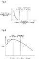
- Fig. 4 shows an output air-fuel ratio that is an air-fuel ratio at which the combustion torque is the maximum and is richer than the stoichiometric air-fuel ratio.
- the cylinder-by-cylinder advancement correction amount ⁇ [i] of the subject cylinder is set to 0 if the air-fuel ratio calculated value ABYF[i] of the subject cylinder is leaner than the output air-fuel ratio, that is, if the combustion in the subject cylinder is performed at an air-fuel ratio leaner than the output air-fuel ratio.
- the cylinder-by-cylinder advancement correction amount ⁇ [i] of the subject cylinder is set to a value that changes in accordance with the air-fuel ratio calculated value ABYF[i] in the following manner. That is, when the air-fuel ratio calculated value ABYF[i] changes from the output air-fuel ratio to a richer value, the air-fuel ratio calculated value ABYF[i] is set to be gradually increased from the value at the time of the output air-fuel ratio (0).
- the engine controller of the present embodiment performs the cylinder-by-cylinder correction of the fuel injection amount to cause differences among the air-fuel ratios of air-fuel mixture burned in multiple cylinders. Accordingly, combustion may be performed at an air-fuel ratio different from the stoichiometric air-fuel ratio.
- the engine controller of the present embodiment separately calculates the gas-blow correction value B[i], the overheat prevention correction value C[i], and the dither control correction value D[i], and may perform combustion at an air-fuel ratio richer than the output air-fuel ratio depending on the situation.
- the cylinder-by-cylinder correction is performed such that the ignition timing of the cylinder in which combustion is performed at an air-fuel ratio richer than the output air-fuel ratio is more advanced than the ignition timings of the other cylinders.
- This increases the torque generated in the cylinder in which combustion is performed at an air-fuel ratio richer than the output air-fuel ratio as indicated by the broken line in Fig. 5 .
- the output efficiency of the engine 10 is prevented from being lowered when the cylinder-by-cylinder correction of the fuel injection amount results in a cylinder in which combustion is performed at an air-fuel ratio richer than the output air-fuel ratio.
- three correction values, or the gas-blow correction value B[i], the overheat prevention correction value C[i], and the dither control correction value D[i] are used as cylinder-by-cylinder correction values for the fuel injection amount for causing differences among the air-fuel ratios in the cylinders.
- the gas-blow correction value B[i] and the dither control correction value D[i] are determined such that the sum of the correction values for the cylinders #1 to #4 is zero.
- the cylinder-by-cylinder correction of the fuel injection amount is performed such that the air-fuel ratio of the entire engine 10, that is, the air-fuel ratio of the total of the air-fuel mixture burned in all the cylinders #1 to #4 is the stoichiometric air-fuel ratio.
- the exhaust gas of all the cylinders #1 to #4 flows into the catalyst device 20 in a mixed state.
- the components of the exhaust gas flowing into the catalyst device 20 are substantially the same as those in a case in which combustion in the cylinders #1 to #4 is performed at the stoichiometric air-fuel ratio. Therefore, in this case, it is possible to perform the cylinder-by-cylinder correction of the fuel injection amount while suppressing deterioration of the exhaust purification performance.
- the cylinder in which the air-fuel ratio has become richer than the stoichiometric air-fuel ratio and the cylinder in which the air-fuel ratio has become leaner than the stoichiometric air-fuel ratio as a result of the cylinder-by-cylinder correction of the fuel injection amount will be referred to as a rich combustion cylinder and a lean combustion cylinder, respectively.
- a rich combustion cylinder and a lean combustion cylinder respectively.
- the present embodiment performs the cylinder-by-cylinder correction of the ignition timing to increase the torque generated in the cylinder in which combustion is performed at an air-fuel ratio richer than the output air-fuel ratio. This limits a decrease in the engine torque when the air-fuel ratio of the rich combustion cylinder becomes richer than the output air-fuel ratio.
- the present embodiment may be modified as follows.
- the present embodiment and the following modifications can be combined as long as the combined modifications remain technically consistent with each other.
- the overheat prevention correction value C[i] may be set such that the sum of the values of the cylinders #1 to #4 becomes zero. In this case, it is possible to limit deterioration of the exhaust purification performance even during execution of the overheat prevention correction.
- the cylinder-by-cylinder correction of the ignition timing is performed by correcting the final ignition timing IG with the cylinder-by-cylinder advancement correction amount ⁇ [i].
- the cylinder-by-cylinder correction of the ignition timing may be performed by correcting the trace knock ignition timing with the cylinder-by-cylinder advancement correction amount ⁇ [i].
- the cylinder-by-cylinder correction of the ignition timing is performed only in the operation region in which the trace knock ignition timing in the state where the fuel injection amount is not subjected to the cylinder-by-cylinder correction is more retarded than the optimum ignition timing.
- the trace knock ignition timing is corrected with the cylinder-by-cylinder advancement correction amount ⁇ [i] it is unnecessary to limit the operating range as described above.
- three correction values, or the gas-blow correction value B[i], the overheat prevention correction value C[i], and the dither control correction value D[i] are employed as the cylinder-by-cylinder correction values in order to cause differences among the air-fuel ratios of the cylinders.
- one or two of the correction values may be omitted.
- correction values other than these may be employed as the cylinder-by-cylinder correction value for which a value is set for each cylinder.
- the electronic control unit 21 is not limited to one that performs software processing on all processes executed by itself.
- the electronic control unit 21 may include at least part of the processes executed by the software in the present embodiment as one that is executed by hardware circuits dedicated to execution of these processes (such as ASIC). That is, the electronic control unit 21 may be modified as long as it has any one of the following configurations (a) to (c).
- a plurality of software processing circuits each including a processor and a program storage device and a plurality of dedicated hardware circuits may be provided. That is, the above processes may be executed in any manner as long as the processes are executed by processing circuitry that includes at least one of a set of one or more software processing circuits and a set of one or more dedicated hardware circuits.
Landscapes
- Engineering & Computer Science (AREA)
- Chemical & Material Sciences (AREA)
- Combustion & Propulsion (AREA)
- Mechanical Engineering (AREA)
- General Engineering & Computer Science (AREA)
- Signal Processing (AREA)
- Theoretical Computer Science (AREA)
- Electrical Control Of Air Or Fuel Supplied To Internal-Combustion Engine (AREA)
- Combined Controls Of Internal Combustion Engines (AREA)
- Electrical Control Of Ignition Timing (AREA)
Claims (7)
- Maschinencontroller (21), aufweisend:einen Kraftstoffeinspritzkorrektor, der so konfiguriert ist, dass er eine Zylinder-für-Zylinder-Korrektur einer Kraftstoffeinspritzmenge durchführt, so dass Differenzen zwischen Luft-/Kraftstoff-Verhältnissen einer Luft-/Kraftstoff-Mischung, die in einer Mehrzahl an Zylindern (#1 bis #4) verbrannt wird, verursacht wird,wobei in einem Fall, bei dem die Zylinder-für-Zylinder-Korrektur der Kraftstoffeinspritzmenge in einem Zylinder resultiert, in dem die Verbrennung bei, einem Luft-/Kraftstoff-Verhältnis durchgeführt wird, das fetter ist als ein ausgegebenes Luft-/Kraftstoff-Verhältnis, wobei das ausgegebene Luft-/KraftstoffVerhältnis ein Luft-/Kraftstoff-Verhältnis ist, bei dem das Drehmoment durch die Verbrennung maximiert ist, der Kraftstoffeinspritzkorrektor so konfiguriert ist, dass er eine Zylinder-für-Zylinder-Korrektur des Zündzeitpunkts durchführt, so dass der Zündzeitpunkt des Zylinders, in dem die Verbrennung bei dem Luft-/KraftstoffVerhältnis durchgeführt wird, das fetter ist als das ausgegebene Luft-/KraftstoffVerhältnis, weiter vorverstellt wird als der Zündzeitpunkt der anderen Zylinder.
- Maschinencontroller (21) nach Anspruch 1, wobei der Kraftstoffeinspritzkorrektor so konfiguriert ist, dass er die Zylinder-für-Zylinder-Korrektur des Zündzeitpunkts unter der Bedingung durchführt, dass eine Maschine (10) in einem Betriebsbereich betrieben wird, in dem ein Klopfverfolgungszündzeitpunkt in einem Zustand, in dem die Zylinder-für-Zylinder-Korrektur der Kraftstoffeinspritzmenge nicht durchgeführt wird, weiter spätverstellt ist als ein optimaler Zündzeitpunkt.
- Maschinencontroller (21) nach Anspruch 1 oder 2, wobei der Kraftstoffeinspritzkorrektor so konfiguriert ist, dass er die Zylinder-für-Zylinder-Korrektur der Kraftstoffeinspritzmenge so durchführt, dass ein Luft-/KraftstoffVerhältnis einer gesamten Maschine (10) ein stöchiometrisches Luft-/KraftstoffVerhältnis wird.
- Maschinencontroller (21) nach einem der Ansprüche 1 bis 3, wobei die Zylinder-für-Zylinder-Korrektur der Kraftstoffeinspritzmenge eine Gasblaskorrektur beinhaltet, die eine Zylinder-für-Zylinder-Korrektur der Kraftstoffeinspritzmenge zum Kompensieren einer stabilen Luft-/Kraftstoff-Verhältnisabweichung ist, die durch Fluktuationen einer Intensität eines Blasens von Abgas von den entsprechenden Zylindern (#1 bis #4) auf einen Luft-/Kraftstoff-Sensor (19) ist, der in einer Abgasleitung (17) einer Maschine (10) angeordnet ist.
- Maschinencontroller (21) nach einem der Ansprüche 1 bis 4, wobei die Zylinder-für-Zylinder-Korrektur der Kraftstoffeinspritzmenge eine Katalysatorüberhitzungsverhinderungskorrektur beinhaltet, die eine Zylinder-für-Zylinder-Korrektur der Kraftstoffeinspritzmenge zum Begrenzen eines Temperaturanstiegs einer Katalysatorvorrichtung (20) ist, die in einer Abgasleitung (17) einer Maschine (10) angeordnet ist.
- Maschinencontroller (21) nach einem der Ansprüche 1 bis 5, wobei die Zylinder-für-Zylinder-Korrektur der Kraftstoffeinspritzmenge eine Schwingsteuerkorrektur beinhaltet, die eine Zylinder-für-Zylinder-Korrektur der Kraftstoffeinspritzmenge zum Herbeiführen eines Temperaturanstiegs einer Katalysatorvorrichtung (20) ist, die in einer Abgasleitung (17) einer Maschine (10) angeordnet ist.
- Maschinensteuerverfahren, aufweisend:Durchführen einer Zylinder-für-Zylinder-Korrektur einer Kraftstoffeinspritzmenge, so dass Differenzen zwischen Luft-/Kraftstoff-Verhältnissen einer Luft-/Kraftstoff-Mischung, die in einer Mehrzahl an Zylindern (#1 bis #4) verbrannt wird, verursacht wird; undin einem Fall, bei dem die Zylinder-für-Zylinder-Korrektur der Kraftstoffeinspritzmenge in einem Zylinder resultiert, in dem die Verbrennung bei einem Luft-/Kraftstoff-Verhältnis durchgeführt wird, das fetter ist als ein ausgegebenes Luft-/Kraftstoff-Verhältnis, das ein Luft-/Kraftstoff-Verhältnis ist, bei dem das Drehmoment durch die Verbrennung maximiert ist, Durchführen einer Zylinder-für-Zylinder-Korrektur des Zündzeitpunkts, so dass der Zündzeitpunkt des Zylinders, in dem die Verbrennung bei dem Luft-/Kraftstoff-Verhältnis durchgeführt wird, das fetter ist als das ausgegebene Luft-/Kraftstoff-Verhältnis, weiter vorverstellt wird als der Zündzeitpunkt der anderen Zylinder.
Applications Claiming Priority (1)
| Application Number | Priority Date | Filing Date | Title |
|---|---|---|---|
| JP2018076114A JP7087609B2 (ja) | 2018-04-11 | 2018-04-11 | エンジン制御装置 |
Publications (2)
| Publication Number | Publication Date |
|---|---|
| EP3553299A1 EP3553299A1 (de) | 2019-10-16 |
| EP3553299B1 true EP3553299B1 (de) | 2022-07-13 |
Family
ID=65801967
Family Applications (1)
| Application Number | Title | Priority Date | Filing Date |
|---|---|---|---|
| EP19162470.9A Active EP3553299B1 (de) | 2018-04-11 | 2019-03-13 | Motorsteuergerät und motorsteuerungsverfahren |
Country Status (4)
| Country | Link |
|---|---|
| US (1) | US10920696B2 (de) |
| EP (1) | EP3553299B1 (de) |
| JP (1) | JP7087609B2 (de) |
| CN (1) | CN110360045B (de) |
Families Citing this family (7)
| Publication number | Priority date | Publication date | Assignee | Title |
|---|---|---|---|---|
| JP6911678B2 (ja) * | 2017-09-27 | 2021-07-28 | トヨタ自動車株式会社 | 内燃機関の制御装置 |
| JP7087609B2 (ja) * | 2018-04-11 | 2022-06-21 | トヨタ自動車株式会社 | エンジン制御装置 |
| WO2020026721A1 (ja) * | 2018-08-02 | 2020-02-06 | マツダ株式会社 | エンジンの制御装置 |
| CN110925110B (zh) * | 2019-12-13 | 2022-08-23 | 潍柴动力股份有限公司 | 发动机怠速控制方法、装置及存储介质 |
| US11365685B2 (en) * | 2020-02-20 | 2022-06-21 | Ford Global Technologies, Llc | Methods and systems for a series gap igniter with a passive prechamber |
| CN114198235B (zh) * | 2021-10-25 | 2023-07-25 | 东风汽车集团股份有限公司 | 点火提前角的计算方法、装置、终端设备及介质 |
| JP2023161331A (ja) * | 2022-04-25 | 2023-11-07 | トヨタ自動車株式会社 | 内燃機関の排気浄化装置 |
Family Cites Families (36)
| Publication number | Priority date | Publication date | Assignee | Title |
|---|---|---|---|---|
| GB8700759D0 (en) * | 1987-01-14 | 1987-02-18 | Lucas Ind Plc | Adaptive control system |
| US5157613A (en) * | 1987-01-14 | 1992-10-20 | Lucas Industries Public Limited Company | Adaptive control system for an engine |
| JPH0689731B2 (ja) * | 1989-03-10 | 1994-11-14 | 株式会社日立製作所 | 内燃機関の点火時期制御方法および装置 |
| US5315823A (en) * | 1991-02-12 | 1994-05-31 | Nippondenso Co., Ltd. | Control apparatus for speedily warming up catalyst in internal combustion engine |
| PH30377A (en) * | 1992-02-11 | 1997-04-15 | Orbital Eng Pty | Air fuel ratio control |
| JPH07269453A (ja) * | 1994-03-28 | 1995-10-17 | Toyota Motor Corp | 内燃機関の点火時期制御方法 |
| JPH09126040A (ja) * | 1995-11-02 | 1997-05-13 | Hitachi Ltd | 内燃機関の制御装置 |
| JPH09209742A (ja) * | 1996-02-05 | 1997-08-12 | Toyota Motor Corp | 過給機付き内燃機関の排気制御装置 |
| JPH09264170A (ja) * | 1996-03-29 | 1997-10-07 | Mazda Motor Corp | エンジンの制御装置 |
| US5758493A (en) * | 1996-12-13 | 1998-06-02 | Ford Global Technologies, Inc. | Method and apparatus for desulfating a NOx trap |
| JPH11287145A (ja) | 1998-04-02 | 1999-10-19 | Toyota Motor Corp | 多気筒内燃機関の空燃比制御装置 |
| WO2002103181A1 (fr) * | 2001-06-18 | 2002-12-27 | Toyota Jidosha Kabushiki Kaisha | Dispositif de commande du rapport air-combustible dans un moteur a combustion interne |
| JP4023115B2 (ja) * | 2001-07-17 | 2007-12-19 | 日産自動車株式会社 | 直噴火花点火式エンジンの制御装置 |
| JP2004108204A (ja) | 2002-09-17 | 2004-04-08 | Denso Corp | 内燃機関用制御装置 |
| US7021287B2 (en) * | 2002-11-01 | 2006-04-04 | Visteon Global Technologies, Inc. | Closed-loop individual cylinder A/F ratio balancing |
| JP2004353552A (ja) | 2003-05-29 | 2004-12-16 | Denso Corp | 内燃機関の触媒早期暖機制御装置 |
| JP2005023806A (ja) * | 2003-06-30 | 2005-01-27 | Toyota Motor Corp | 内燃機関の点火時期制御装置 |
| DE102004051651A1 (de) * | 2004-10-22 | 2006-05-04 | Robert Bosch Gmbh | Verfahren zum Betreiben einer Brennkraftmaschine |
| US7707822B2 (en) | 2006-08-08 | 2010-05-04 | Denso Corporation | Cylinder air-fuel ratio controller for internal combustion engine |
| JP4788647B2 (ja) | 2007-04-26 | 2011-10-05 | トヨタ自動車株式会社 | 内燃機関の制御装置 |
| JP4507016B2 (ja) * | 2008-02-15 | 2010-07-21 | 三菱自動車工業株式会社 | 内燃機関の制御装置 |
| JP4609541B2 (ja) | 2008-07-18 | 2011-01-12 | トヨタ自動車株式会社 | 過給機付き内燃機関の制御装置 |
| JP2010168949A (ja) | 2009-01-21 | 2010-08-05 | Toyota Motor Corp | 内燃機関の制御装置、FFV(FlexibleFuelVehicle) |
| US8600647B2 (en) | 2009-01-30 | 2013-12-03 | Toyota Jidosha Kabushiki Kaisha | Air-fuel ratio control apparatus of a multi-cylinder internal combustion engine |
| JP5103459B2 (ja) | 2009-10-30 | 2012-12-19 | 日立オートモティブシステムズ株式会社 | エンジンの制御装置 |
| JP5540729B2 (ja) * | 2010-01-27 | 2014-07-02 | マツダ株式会社 | 過給機付エンジンの制御方法および制御装置 |
| DE112010005904B4 (de) | 2010-09-24 | 2016-05-12 | Toyota Jidosha Kabushiki Kaisha | Luft-Kraftstoff-Verhältnis-Steuervorrichtung für eine Verbrennungsmaschine |
| JP5505447B2 (ja) | 2012-03-28 | 2014-05-28 | トヨタ自動車株式会社 | 内燃機関の制御装置 |
| JP6001920B2 (ja) | 2012-05-22 | 2016-10-05 | 富士重工業株式会社 | エンジンの燃焼制御装置 |
| JP2014070511A (ja) | 2012-09-27 | 2014-04-21 | Daihatsu Motor Co Ltd | 内燃機関の制御装置 |
| WO2014167649A1 (ja) * | 2013-04-09 | 2014-10-16 | トヨタ自動車株式会社 | 内燃機関の制御装置 |
| JP2016031050A (ja) | 2014-07-29 | 2016-03-07 | 三菱自動車工業株式会社 | 内燃機関の排気浄化装置 |
| JP6462311B2 (ja) * | 2014-10-24 | 2019-01-30 | 日立オートモティブシステムズ株式会社 | エンジンの制御装置 |
| US9932922B2 (en) * | 2014-10-30 | 2018-04-03 | Ford Global Technologies, Llc | Post-catalyst cylinder imbalance monitor |
| JP2017141693A (ja) | 2016-02-08 | 2017-08-17 | トヨタ自動車株式会社 | 内燃機関の制御装置 |
| JP7087609B2 (ja) * | 2018-04-11 | 2022-06-21 | トヨタ自動車株式会社 | エンジン制御装置 |
-
2018
- 2018-04-11 JP JP2018076114A patent/JP7087609B2/ja active Active
-
2019
- 2019-03-13 EP EP19162470.9A patent/EP3553299B1/de active Active
- 2019-03-20 US US16/358,830 patent/US10920696B2/en not_active Expired - Fee Related
- 2019-04-09 CN CN201910280473.4A patent/CN110360045B/zh not_active Expired - Fee Related
Also Published As
| Publication number | Publication date |
|---|---|
| CN110360045B (zh) | 2021-09-17 |
| CN110360045A (zh) | 2019-10-22 |
| EP3553299A1 (de) | 2019-10-16 |
| JP2019183752A (ja) | 2019-10-24 |
| JP7087609B2 (ja) | 2022-06-21 |
| US10920696B2 (en) | 2021-02-16 |
| US20190316535A1 (en) | 2019-10-17 |
Similar Documents
| Publication | Publication Date | Title |
|---|---|---|
| EP3553299B1 (de) | Motorsteuergerät und motorsteuerungsverfahren | |
| EP3068998B1 (de) | Regler für einen verbrennungsmotor | |
| JP5278466B2 (ja) | 気筒間空燃比ばらつき異常検出装置 | |
| US10677180B2 (en) | Controller and control method for internal combustion engine | |
| JP3680432B2 (ja) | 内燃機関の制御装置 | |
| JP7754125B2 (ja) | 水素エンジンの制御装置 | |
| JP4943873B2 (ja) | 筒内噴射式火花点火内燃機関の制御装置 | |
| US10563602B2 (en) | Controller and control method for internal combustion engine | |
| US9261066B2 (en) | Ignition timing control device and ignition timing control method for internal combustion engine | |
| US11149705B2 (en) | Engine controller and engine control method | |
| JP2008095539A (ja) | 予混合圧縮着火内燃機関 | |
| JP2010168931A (ja) | 火花点火式内燃機関の点火時期制御装置 | |
| JP2009250164A (ja) | 内燃機関の制御装置 | |
| JPH04136482A (ja) | オクタン価検出方法 | |
| JP3968902B2 (ja) | 点火時期制御装置 | |
| JP2008261226A (ja) | 内燃機関の燃料セタン価判別システム | |
| EP3492725B1 (de) | Kraftstoffeinspritzsteuergerät und steuerungsverfahren für motor | |
| JP6828646B2 (ja) | 内燃機関の制御装置 | |
| JPH03194153A (ja) | ノッキング制御機能付内燃機関の燃料供給制御装置 | |
| JPS62203942A (ja) | 内燃機関の制御装置 | |
| JP2007182904A (ja) | 点火時期制御装置 | |
| JP2000213391A (ja) | 内燃機関の制御装置 | |
| JP2008202413A (ja) | 内燃機関の燃料制御装置 | |
| JPH05113147A (ja) | 内燃機関の制御装置 | |
| JPH08326576A (ja) | エンジンの燃焼制御装置 |
Legal Events
| Date | Code | Title | Description |
|---|---|---|---|
| PUAI | Public reference made under article 153(3) epc to a published international application that has entered the european phase |
Free format text: ORIGINAL CODE: 0009012 |
|
| STAA | Information on the status of an ep patent application or granted ep patent |
Free format text: STATUS: REQUEST FOR EXAMINATION WAS MADE |
|
| 17P | Request for examination filed |
Effective date: 20190313 |
|
| AK | Designated contracting states |
Kind code of ref document: A1 Designated state(s): AL AT BE BG CH CY CZ DE DK EE ES FI FR GB GR HR HU IE IS IT LI LT LU LV MC MK MT NL NO PL PT RO RS SE SI SK SM TR |
|
| AX | Request for extension of the european patent |
Extension state: BA ME |
|
| GRAP | Despatch of communication of intention to grant a patent |
Free format text: ORIGINAL CODE: EPIDOSNIGR1 |
|
| STAA | Information on the status of an ep patent application or granted ep patent |
Free format text: STATUS: GRANT OF PATENT IS INTENDED |
|
| INTG | Intention to grant announced |
Effective date: 20220225 |
|
| GRAS | Grant fee paid |
Free format text: ORIGINAL CODE: EPIDOSNIGR3 |
|
| GRAA | (expected) grant |
Free format text: ORIGINAL CODE: 0009210 |
|
| STAA | Information on the status of an ep patent application or granted ep patent |
Free format text: STATUS: THE PATENT HAS BEEN GRANTED |
|
| RIN1 | Information on inventor provided before grant (corrected) |
Inventor name: IDOGAWA, MASANAO Inventor name: IMAI, SOHICHI |
|
| AK | Designated contracting states |
Kind code of ref document: B1 Designated state(s): AL AT BE BG CH CY CZ DE DK EE ES FI FR GB GR HR HU IE IS IT LI LT LU LV MC MK MT NL NO PL PT RO RS SE SI SK SM TR |
|
| REG | Reference to a national code |
Ref country code: CH Ref legal event code: EP |
|
| REG | Reference to a national code |
Ref country code: DE Ref legal event code: R096 Ref document number: 602019016875 Country of ref document: DE |
|
| REG | Reference to a national code |
Ref country code: AT Ref legal event code: REF Ref document number: 1504411 Country of ref document: AT Kind code of ref document: T Effective date: 20220815 |
|
| REG | Reference to a national code |
Ref country code: IE Ref legal event code: FG4D |
|
| REG | Reference to a national code |
Ref country code: LT Ref legal event code: MG9D |
|
| REG | Reference to a national code |
Ref country code: NL Ref legal event code: MP Effective date: 20220713 |
|
| PG25 | Lapsed in a contracting state [announced via postgrant information from national office to epo] |
Ref country code: SE Free format text: LAPSE BECAUSE OF FAILURE TO SUBMIT A TRANSLATION OF THE DESCRIPTION OR TO PAY THE FEE WITHIN THE PRESCRIBED TIME-LIMIT Effective date: 20220713 Ref country code: RS Free format text: LAPSE BECAUSE OF FAILURE TO SUBMIT A TRANSLATION OF THE DESCRIPTION OR TO PAY THE FEE WITHIN THE PRESCRIBED TIME-LIMIT Effective date: 20220713 Ref country code: PT Free format text: LAPSE BECAUSE OF FAILURE TO SUBMIT A TRANSLATION OF THE DESCRIPTION OR TO PAY THE FEE WITHIN THE PRESCRIBED TIME-LIMIT Effective date: 20221114 Ref country code: NO Free format text: LAPSE BECAUSE OF FAILURE TO SUBMIT A TRANSLATION OF THE DESCRIPTION OR TO PAY THE FEE WITHIN THE PRESCRIBED TIME-LIMIT Effective date: 20221013 Ref country code: NL Free format text: LAPSE BECAUSE OF FAILURE TO SUBMIT A TRANSLATION OF THE DESCRIPTION OR TO PAY THE FEE WITHIN THE PRESCRIBED TIME-LIMIT Effective date: 20220713 Ref country code: LV Free format text: LAPSE BECAUSE OF FAILURE TO SUBMIT A TRANSLATION OF THE DESCRIPTION OR TO PAY THE FEE WITHIN THE PRESCRIBED TIME-LIMIT Effective date: 20220713 Ref country code: LT Free format text: LAPSE BECAUSE OF FAILURE TO SUBMIT A TRANSLATION OF THE DESCRIPTION OR TO PAY THE FEE WITHIN THE PRESCRIBED TIME-LIMIT Effective date: 20220713 Ref country code: FI Free format text: LAPSE BECAUSE OF FAILURE TO SUBMIT A TRANSLATION OF THE DESCRIPTION OR TO PAY THE FEE WITHIN THE PRESCRIBED TIME-LIMIT Effective date: 20220713 Ref country code: ES Free format text: LAPSE BECAUSE OF FAILURE TO SUBMIT A TRANSLATION OF THE DESCRIPTION OR TO PAY THE FEE WITHIN THE PRESCRIBED TIME-LIMIT Effective date: 20220713 |
|
| REG | Reference to a national code |
Ref country code: AT Ref legal event code: MK05 Ref document number: 1504411 Country of ref document: AT Kind code of ref document: T Effective date: 20220713 |
|
| PG25 | Lapsed in a contracting state [announced via postgrant information from national office to epo] |
Ref country code: PL Free format text: LAPSE BECAUSE OF FAILURE TO SUBMIT A TRANSLATION OF THE DESCRIPTION OR TO PAY THE FEE WITHIN THE PRESCRIBED TIME-LIMIT Effective date: 20220713 Ref country code: IS Free format text: LAPSE BECAUSE OF FAILURE TO SUBMIT A TRANSLATION OF THE DESCRIPTION OR TO PAY THE FEE WITHIN THE PRESCRIBED TIME-LIMIT Effective date: 20221113 Ref country code: HR Free format text: LAPSE BECAUSE OF FAILURE TO SUBMIT A TRANSLATION OF THE DESCRIPTION OR TO PAY THE FEE WITHIN THE PRESCRIBED TIME-LIMIT Effective date: 20220713 Ref country code: GR Free format text: LAPSE BECAUSE OF FAILURE TO SUBMIT A TRANSLATION OF THE DESCRIPTION OR TO PAY THE FEE WITHIN THE PRESCRIBED TIME-LIMIT Effective date: 20221014 |
|
| REG | Reference to a national code |
Ref country code: DE Ref legal event code: R097 Ref document number: 602019016875 Country of ref document: DE |
|
| PG25 | Lapsed in a contracting state [announced via postgrant information from national office to epo] |
Ref country code: SM Free format text: LAPSE BECAUSE OF FAILURE TO SUBMIT A TRANSLATION OF THE DESCRIPTION OR TO PAY THE FEE WITHIN THE PRESCRIBED TIME-LIMIT Effective date: 20220713 Ref country code: RO Free format text: LAPSE BECAUSE OF FAILURE TO SUBMIT A TRANSLATION OF THE DESCRIPTION OR TO PAY THE FEE WITHIN THE PRESCRIBED TIME-LIMIT Effective date: 20220713 Ref country code: DK Free format text: LAPSE BECAUSE OF FAILURE TO SUBMIT A TRANSLATION OF THE DESCRIPTION OR TO PAY THE FEE WITHIN THE PRESCRIBED TIME-LIMIT Effective date: 20220713 Ref country code: CZ Free format text: LAPSE BECAUSE OF FAILURE TO SUBMIT A TRANSLATION OF THE DESCRIPTION OR TO PAY THE FEE WITHIN THE PRESCRIBED TIME-LIMIT Effective date: 20220713 Ref country code: AT Free format text: LAPSE BECAUSE OF FAILURE TO SUBMIT A TRANSLATION OF THE DESCRIPTION OR TO PAY THE FEE WITHIN THE PRESCRIBED TIME-LIMIT Effective date: 20220713 |
|
| PLBE | No opposition filed within time limit |
Free format text: ORIGINAL CODE: 0009261 |
|
| STAA | Information on the status of an ep patent application or granted ep patent |
Free format text: STATUS: NO OPPOSITION FILED WITHIN TIME LIMIT |
|
| PG25 | Lapsed in a contracting state [announced via postgrant information from national office to epo] |
Ref country code: SK Free format text: LAPSE BECAUSE OF FAILURE TO SUBMIT A TRANSLATION OF THE DESCRIPTION OR TO PAY THE FEE WITHIN THE PRESCRIBED TIME-LIMIT Effective date: 20220713 Ref country code: EE Free format text: LAPSE BECAUSE OF FAILURE TO SUBMIT A TRANSLATION OF THE DESCRIPTION OR TO PAY THE FEE WITHIN THE PRESCRIBED TIME-LIMIT Effective date: 20220713 |
|
| PGFP | Annual fee paid to national office [announced via postgrant information from national office to epo] |
Ref country code: DE Payment date: 20230131 Year of fee payment: 5 |
|
| P01 | Opt-out of the competence of the unified patent court (upc) registered |
Effective date: 20230427 |
|
| 26N | No opposition filed |
Effective date: 20230414 |
|
| REG | Reference to a national code |
Ref country code: DE Ref legal event code: R084 Ref document number: 602019016875 Country of ref document: DE |
|
| PG25 | Lapsed in a contracting state [announced via postgrant information from national office to epo] |
Ref country code: AL Free format text: LAPSE BECAUSE OF FAILURE TO SUBMIT A TRANSLATION OF THE DESCRIPTION OR TO PAY THE FEE WITHIN THE PRESCRIBED TIME-LIMIT Effective date: 20220713 |
|
| PG25 | Lapsed in a contracting state [announced via postgrant information from national office to epo] |
Ref country code: SI Free format text: LAPSE BECAUSE OF FAILURE TO SUBMIT A TRANSLATION OF THE DESCRIPTION OR TO PAY THE FEE WITHIN THE PRESCRIBED TIME-LIMIT Effective date: 20220713 |
|
| PG25 | Lapsed in a contracting state [announced via postgrant information from national office to epo] |
Ref country code: MC Free format text: LAPSE BECAUSE OF FAILURE TO SUBMIT A TRANSLATION OF THE DESCRIPTION OR TO PAY THE FEE WITHIN THE PRESCRIBED TIME-LIMIT Effective date: 20220713 |
|
| REG | Reference to a national code |
Ref country code: CH Ref legal event code: PL |
|
| GBPC | Gb: european patent ceased through non-payment of renewal fee |
Effective date: 20230313 |
|
| REG | Reference to a national code |
Ref country code: BE Ref legal event code: MM Effective date: 20230331 |
|
| PG25 | Lapsed in a contracting state [announced via postgrant information from national office to epo] |
Ref country code: LU Free format text: LAPSE BECAUSE OF NON-PAYMENT OF DUE FEES Effective date: 20230313 |
|
| REG | Reference to a national code |
Ref country code: IE Ref legal event code: MM4A |
|
| PG25 | Lapsed in a contracting state [announced via postgrant information from national office to epo] |
Ref country code: GB Free format text: LAPSE BECAUSE OF NON-PAYMENT OF DUE FEES Effective date: 20230313 |
|
| PG25 | Lapsed in a contracting state [announced via postgrant information from national office to epo] |
Ref country code: LI Free format text: LAPSE BECAUSE OF NON-PAYMENT OF DUE FEES Effective date: 20230331 Ref country code: IT Free format text: LAPSE BECAUSE OF FAILURE TO SUBMIT A TRANSLATION OF THE DESCRIPTION OR TO PAY THE FEE WITHIN THE PRESCRIBED TIME-LIMIT Effective date: 20220713 Ref country code: IE Free format text: LAPSE BECAUSE OF NON-PAYMENT OF DUE FEES Effective date: 20230313 Ref country code: GB Free format text: LAPSE BECAUSE OF NON-PAYMENT OF DUE FEES Effective date: 20230313 Ref country code: FR Free format text: LAPSE BECAUSE OF NON-PAYMENT OF DUE FEES Effective date: 20230331 Ref country code: CH Free format text: LAPSE BECAUSE OF NON-PAYMENT OF DUE FEES Effective date: 20230331 |
|
| PG25 | Lapsed in a contracting state [announced via postgrant information from national office to epo] |
Ref country code: BE Free format text: LAPSE BECAUSE OF NON-PAYMENT OF DUE FEES Effective date: 20230331 |
|
| REG | Reference to a national code |
Ref country code: DE Ref legal event code: R119 Ref document number: 602019016875 Country of ref document: DE |
|
| PG25 | Lapsed in a contracting state [announced via postgrant information from national office to epo] |
Ref country code: BG Free format text: LAPSE BECAUSE OF FAILURE TO SUBMIT A TRANSLATION OF THE DESCRIPTION OR TO PAY THE FEE WITHIN THE PRESCRIBED TIME-LIMIT Effective date: 20220713 |
|
| PG25 | Lapsed in a contracting state [announced via postgrant information from national office to epo] |
Ref country code: BG Free format text: LAPSE BECAUSE OF FAILURE TO SUBMIT A TRANSLATION OF THE DESCRIPTION OR TO PAY THE FEE WITHIN THE PRESCRIBED TIME-LIMIT Effective date: 20220713 |
|
| PG25 | Lapsed in a contracting state [announced via postgrant information from national office to epo] |
Ref country code: DE Free format text: LAPSE BECAUSE OF NON-PAYMENT OF DUE FEES Effective date: 20241001 |
|
| PG25 | Lapsed in a contracting state [announced via postgrant information from national office to epo] |
Ref country code: DE Free format text: LAPSE BECAUSE OF NON-PAYMENT OF DUE FEES Effective date: 20241001 |
|
| PG25 | Lapsed in a contracting state [announced via postgrant information from national office to epo] |
Ref country code: CY Free format text: LAPSE BECAUSE OF FAILURE TO SUBMIT A TRANSLATION OF THE DESCRIPTION OR TO PAY THE FEE WITHIN THE PRESCRIBED TIME-LIMIT; INVALID AB INITIO Effective date: 20190313 |
|
| PG25 | Lapsed in a contracting state [announced via postgrant information from national office to epo] |
Ref country code: HU Free format text: LAPSE BECAUSE OF FAILURE TO SUBMIT A TRANSLATION OF THE DESCRIPTION OR TO PAY THE FEE WITHIN THE PRESCRIBED TIME-LIMIT; INVALID AB INITIO Effective date: 20190313 |
|
| PG25 | Lapsed in a contracting state [announced via postgrant information from national office to epo] |
Ref country code: TR Free format text: LAPSE BECAUSE OF FAILURE TO SUBMIT A TRANSLATION OF THE DESCRIPTION OR TO PAY THE FEE WITHIN THE PRESCRIBED TIME-LIMIT Effective date: 20220713 |