EP3551528B1 - Suspension group for motor vehicle, wheel group for motor vehicle, front end of a motor vehicle and motor vehicle thereof - Google Patents
Suspension group for motor vehicle, wheel group for motor vehicle, front end of a motor vehicle and motor vehicle thereof Download PDFInfo
- Publication number
- EP3551528B1 EP3551528B1 EP17826287.9A EP17826287A EP3551528B1 EP 3551528 B1 EP3551528 B1 EP 3551528B1 EP 17826287 A EP17826287 A EP 17826287A EP 3551528 B1 EP3551528 B1 EP 3551528B1
- Authority
- EP
- European Patent Office
- Prior art keywords
- wheel
- group
- crank
- suspension
- shock absorber
- Prior art date
- Legal status (The legal status is an assumption and is not a legal conclusion. Google has not performed a legal analysis and makes no representation as to the accuracy of the status listed.)
- Active
Links
- 239000000725 suspension Substances 0.000 title claims description 69
- 239000006096 absorbing agent Substances 0.000 claims description 55
- 230000035939 shock Effects 0.000 claims description 55
- 238000005096 rolling process Methods 0.000 claims description 9
- 230000008878 coupling Effects 0.000 description 3
- 238000010168 coupling process Methods 0.000 description 3
- 238000005859 coupling reaction Methods 0.000 description 3
- 238000004519 manufacturing process Methods 0.000 description 2
- 239000000463 material Substances 0.000 description 2
- 238000009825 accumulation Methods 0.000 description 1
- 230000006978 adaptation Effects 0.000 description 1
- 230000008901 benefit Effects 0.000 description 1
- 238000006243 chemical reaction Methods 0.000 description 1
- 230000006835 compression Effects 0.000 description 1
- 238000007906 compression Methods 0.000 description 1
- 238000010276 construction Methods 0.000 description 1
- 238000013016 damping Methods 0.000 description 1
- 230000006866 deterioration Effects 0.000 description 1
- 230000014509 gene expression Effects 0.000 description 1
- 238000012986 modification Methods 0.000 description 1
- 230000004048 modification Effects 0.000 description 1
- 230000004044 response Effects 0.000 description 1
Images


Classifications
-
- B—PERFORMING OPERATIONS; TRANSPORTING
- B62—LAND VEHICLES FOR TRAVELLING OTHERWISE THAN ON RAILS
- B62K—CYCLES; CYCLE FRAMES; CYCLE STEERING DEVICES; RIDER-OPERATED TERMINAL CONTROLS SPECIALLY ADAPTED FOR CYCLES; CYCLE AXLE SUSPENSIONS; CYCLE SIDE-CARS, FORECARS, OR THE LIKE
- B62K5/00—Cycles with handlebars, equipped with three or more main road wheels
- B62K5/02—Tricycles
- B62K5/027—Motorcycles with three wheels
-
- B—PERFORMING OPERATIONS; TRANSPORTING
- B60—VEHICLES IN GENERAL
- B60G—VEHICLE SUSPENSION ARRANGEMENTS
- B60G3/00—Resilient suspensions for a single wheel
- B60G3/02—Resilient suspensions for a single wheel with a single pivoted arm
- B60G3/04—Resilient suspensions for a single wheel with a single pivoted arm the arm being essentially transverse to the longitudinal axis of the vehicle
-
- B—PERFORMING OPERATIONS; TRANSPORTING
- B60—VEHICLES IN GENERAL
- B60G—VEHICLE SUSPENSION ARRANGEMENTS
- B60G13/00—Resilient suspensions characterised by arrangement, location or type of vibration dampers
- B60G13/001—Arrangements for attachment of dampers
- B60G13/005—Arrangements for attachment of dampers characterised by the mounting on the axle or suspension arm of the damper unit
-
- B—PERFORMING OPERATIONS; TRANSPORTING
- B60—VEHICLES IN GENERAL
- B60G—VEHICLE SUSPENSION ARRANGEMENTS
- B60G3/00—Resilient suspensions for a single wheel
- B60G3/01—Resilient suspensions for a single wheel the wheel being mounted for sliding movement, e.g. in or on a vertical guide
-
- B—PERFORMING OPERATIONS; TRANSPORTING
- B60—VEHICLES IN GENERAL
- B60G—VEHICLE SUSPENSION ARRANGEMENTS
- B60G3/00—Resilient suspensions for a single wheel
- B60G3/18—Resilient suspensions for a single wheel with two or more pivoted arms, e.g. parallelogram
- B60G3/20—Resilient suspensions for a single wheel with two or more pivoted arms, e.g. parallelogram all arms being rigid
-
- B—PERFORMING OPERATIONS; TRANSPORTING
- B60—VEHICLES IN GENERAL
- B60G—VEHICLE SUSPENSION ARRANGEMENTS
- B60G7/00—Pivoted suspension arms; Accessories thereof
- B60G7/001—Suspension arms, e.g. constructional features
-
- B—PERFORMING OPERATIONS; TRANSPORTING
- B62—LAND VEHICLES FOR TRAVELLING OTHERWISE THAN ON RAILS
- B62K—CYCLES; CYCLE FRAMES; CYCLE STEERING DEVICES; RIDER-OPERATED TERMINAL CONTROLS SPECIALLY ADAPTED FOR CYCLES; CYCLE AXLE SUSPENSIONS; CYCLE SIDE-CARS, FORECARS, OR THE LIKE
- B62K25/00—Axle suspensions
-
- B—PERFORMING OPERATIONS; TRANSPORTING
- B62—LAND VEHICLES FOR TRAVELLING OTHERWISE THAN ON RAILS
- B62K—CYCLES; CYCLE FRAMES; CYCLE STEERING DEVICES; RIDER-OPERATED TERMINAL CONTROLS SPECIALLY ADAPTED FOR CYCLES; CYCLE AXLE SUSPENSIONS; CYCLE SIDE-CARS, FORECARS, OR THE LIKE
- B62K5/00—Cycles with handlebars, equipped with three or more main road wheels
- B62K5/08—Cycles with handlebars, equipped with three or more main road wheels with steering devices acting on two or more wheels
-
- B—PERFORMING OPERATIONS; TRANSPORTING
- B62—LAND VEHICLES FOR TRAVELLING OTHERWISE THAN ON RAILS
- B62K—CYCLES; CYCLE FRAMES; CYCLE STEERING DEVICES; RIDER-OPERATED TERMINAL CONTROLS SPECIALLY ADAPTED FOR CYCLES; CYCLE AXLE SUSPENSIONS; CYCLE SIDE-CARS, FORECARS, OR THE LIKE
- B62K5/00—Cycles with handlebars, equipped with three or more main road wheels
- B62K5/10—Cycles with handlebars, equipped with three or more main road wheels with means for inwardly inclining the vehicle body on bends
-
- B—PERFORMING OPERATIONS; TRANSPORTING
- B60—VEHICLES IN GENERAL
- B60G—VEHICLE SUSPENSION ARRANGEMENTS
- B60G2204/00—Indexing codes related to suspensions per se or to auxiliary parts
- B60G2204/10—Mounting of suspension elements
- B60G2204/30—In-wheel mountings
-
- B—PERFORMING OPERATIONS; TRANSPORTING
- B60—VEHICLES IN GENERAL
- B60G—VEHICLE SUSPENSION ARRANGEMENTS
- B60G2300/00—Indexing codes relating to the type of vehicle
- B60G2300/12—Cycles; Motorcycles
- B60G2300/122—Trikes
-
- B—PERFORMING OPERATIONS; TRANSPORTING
- B60—VEHICLES IN GENERAL
- B60G—VEHICLE SUSPENSION ARRANGEMENTS
- B60G2300/00—Indexing codes relating to the type of vehicle
- B60G2300/45—Rolling frame vehicles
-
- B—PERFORMING OPERATIONS; TRANSPORTING
- B62—LAND VEHICLES FOR TRAVELLING OTHERWISE THAN ON RAILS
- B62K—CYCLES; CYCLE FRAMES; CYCLE STEERING DEVICES; RIDER-OPERATED TERMINAL CONTROLS SPECIALLY ADAPTED FOR CYCLES; CYCLE AXLE SUSPENSIONS; CYCLE SIDE-CARS, FORECARS, OR THE LIKE
- B62K5/00—Cycles with handlebars, equipped with three or more main road wheels
- B62K2005/001—Suspension details for cycles with three or more main road wheels
Definitions
- the present invention relates to a suspension group of a wheel of a three wheel motorcycle.
- the present invention relates to a wheel group of a three wheel motorcycle which integrates said suspension group, both in a three wheel motorcycle front end and in a three wheel motorcycle thereof.
- the suspensions must guarantee a predetermined stiffness to the wheel support and, at the same time, provide reduced dimensions and weight to improve the dynamic behavior of the vehicle, particularly in three-wheeled motor vehicles.
- the latter comprise a drive wheel at the rear and two wheels at the front of the steering and tilting type.
- the rear wheel has the purpose of providing the drive torque, while the front wheels - substantially parallel to each other - provide the directionality of the vehicle.
- the front wheels are kinematically connected to each other by means of kinematic systems which ensure that the same will roll and/or steer synchronously and symmetrically, for example, via the interposition of articulated quadrilaterals.
- a suspension group with a quadrilateral structure is known in the name of the same applicant which comprises a wheel guide equipped with a shock absorber group integrated inside a jacket.
- the wheel guide is in turn connected to a support arm by means of: a crank, hinged at respective ends of the wheel guide and of the support arm, and a guide rod, keyed to a head of the shock absorber group slidably coupled inside the jacket.
- the travel of the guide rod is defined by a slot made on the jacket.
- the head of the shock absorber group forms a cylinder-piston coupling and acts as an axial guide for the sliding of the shock absorber group.
- the aforementioned solution while being functionally valid, has some drawbacks.
- the head portion is open towards the outside through the slot and, therefore, the cylinder-piston coupling is subject to the accumulation of dirt; this aspect may cause deterioration of the seal and of the functionality in general.
- WO 2017/021905 A1 discloses all of the features of claim 1, with the exception of the suspension quadrilateral and its associated features.
- a total schematic view of a three wheel motorcycle according to the present invention is collectively indicated at 100.
- three wheel motorcycle is to be considered in the broad sense, comprising any motorcycle having at least three wheels, i.e., two front wheels 102,102a, as better described below, and at least one rear wheel 103.
- quadricycles are also included in the definition of a motor vehicle, having two wheels on the front end and two wheels on the rear axle.
- the three wheel motorcycle 100 comprises a chassis 101 extending from a front end 108, supporting at least two front wheels 102, 102a, to a rear axle 109, supporting one or more rear wheels 103.
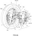
- a right front wheel 102 shown schematically in figure 2a
- a left front wheel 102a with respect to a driver on board the vehicle according to the direction of travel are identified.
- the wheels 102,102a are disposed to the left and to the right of a centerline plane M-M of the motor vehicle, relative to the observation point of a driver thereof.
- the chassis 101 of the three wheel motorcycle may be of any shape and size and may, for example, be of the lattice-type, box-type, single- or double-cradle, and so on.
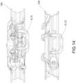
- the front end 108 of the three wheel motorcycle 100 comprises a front end frame 116 and a pair of front wheels 102, 102a, kinematically connected to the front end chassis 116 by a rolling articulated quadrilateral 120.
- Said rolling articulated quadrilateral 120 allows the front wheels 102, 102a to roll, that is to say, incline with respect to the perpendicular to the ground.
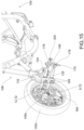
- the front end 108 comprises, at each front wheel 102,102a, a suspension group 10.
- the suspension group 10 comprises a wheel guide 1, which extends along a longitudinal axis T-T.
- the wheel guide 1 provides a wheel attachment 2 for connection to a rotation pin 3 of a wheel 102,102a with a rotation axis R-R orthogonal to the longitudinal axis T-T.
- the wheel guide 1 extends between a first end 1a and a second end 1b, opposite to each other.
- the suspension group 10 further comprises a shock absorber group 7 which extends from a base portion 7a to a head portion 7b, opposite to the base portion 7a, said base and head portion being mutually movable and connected to at least two elements between the wheel guide 1, a support arm 8, a first crank 9 and a crank 12, better described hereinafter.
- a shock absorber group 7 which extends from a base portion 7a to a head portion 7b, opposite to the base portion 7a, said base and head portion being mutually movable and connected to at least two elements between the wheel guide 1, a support arm 8, a first crank 9 and a crank 12, better described hereinafter.
- said shock absorber group 7 comprises resilient means 72 and a damper 71.
- the suspension group 10 comprises a support arm 8 functionally connected to the wheel guide 1 respectively by means of a first crank 9 and a second crank 12.
- the first crank 9 is pivotally connected at said second end 1b to the wheel guide 1, for example by means of a first hinge 9a, and to the support arm 8, for example by means of a second hinge 9b.
- the second crank 12 is pivotally connected at said first end 1a to the wheel guide 1 and to the support arm 8.
- the second crank 12 is pivotally connected at said first end 1a, by means of a third hinge 12a disposed on the support arm 8, and by means of a fourth hinge 12b disposed on the wheel guide 1,
- the first crank 9 is pivotally connected at said second end 1b, by means of a first hinge 9a disposed on the wheel guide 1, and a second hinge 9b disposed on the support arm 8.
- the wheel guide 1, the support arm 8 and the first 9 and second 12 crank define collectively an articulated suspension quadrilateral.
- Each wheel is pivotally connected to its own articulated suspension quadrilateral.
- the suspension quadrilaterals are connected to each other by means of the rolling articulated quadrilateral 120.
- the rolling articulated quadrilateral 120 then connects the suspension quadrilaterals to the chassis of the three wheel motorcycle.
- a shock absorber group 7 is interconnected in such a way that the shock absorber group 7 varies its extension when the movement of the suspension quadrilateral varies.
- such shock absorber group comprises resilient means 72, typically but not exclusively a coil spring or a torsion bar, and a damper 71.
- the resilient means 72 and the damper 71 are not necessarily disposed between the same two elements chosen between the wheel guide 1, the support arm 8, the first crank 9 and the second crank 12. Therefore, the resilient means 72 and the damper 71, if integrated together, connect the same elements of the suspension quadrilateral, while if disengaged, may connect the same elements of the quadrilateral or distinct pairs of elements of the suspension quadrilateral.
- the shock absorber group is provided between said first crank 9 and said second crank 12.
- the shock absorber group 7 is provided between said first crank 9 and said support arm 8.
- the shock absorber group 7 is provided between said first crank 9 and said wheel guide 1.
- the shock absorber group 7 is provided between said second crank 12 and said support arm 8.
- the shock absorber group 7 is provided between said second crank 12 and said wheel guide 1.
- the shock absorber group 7 is provided between said support arm 8 and said wheel guide 1.
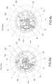
- the resilient means 72 are disposed so as to compress with the increasing load on the wheel 102,102a: this condition is illustrated schematically in figure 1a , wherein various possible inclinations/arrangements of resilient means 72 are illustrated which are compressed as described.
- the resilient means 72 are disposed so as to extend with the increasing load on the wheel 102,102a: this condition is illustrated schematically in figure 1b , wherein various possible inclinations/arrangements of resilient means 72 are illustrated which are extended as described.
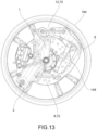
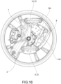
- the suspension quadrilateral 10 is contained within a volume 180 defined by a rim 184 of said wheel 102,102a, i.e. the empty space which, according to a radial direction, is found inside the rim 184.
- the shock absorber 7 may be arranged at least partially outside said volume 184, according to an axial direction.
- the shock absorber 7, in this configuration is at least partially cantilevered or disposed outwardly with respect to the volume 180.
- the shock absorber is preferably doubly hinged to said first and second crank 9,12, so as to rotate with the latter.
- the shock absorber has a floating anchor.
- the shock absorber 7 is disposed completely outwardly or cantilevered with respect to the volume 180, from an inner side of the wheel, facing towards said centerline plane M-M.
- the shock absorber 7 has simplified couplings at the ends 7a,7b and its external positioning allows a greater margin of maneuverability for its size, since its hydraulic body and the spring do not constrain the dimensions of the passage inside the stub axle. Moreover, due to the positioning outside of the volume 180, it is possible to obtain a behavior with a high geometric progressivity which allows springs with a single elastic coefficient to be used.
- the resilient means 72 typically comprise coil springs with coils wound according to a constant or even variable pitch.
- the resilient means are springs disposed coaxially with the shock absorber 7, in a known manner.
- the resilient means 72 may be mounted either in series or in parallel with respect to the shock absorber 7.
- the resilient means 72 are disposed parallel to the shock absorber 7.
- the first and second hinges 9a,9b of the first crank 9 are rigid or interlocking so that the first crank 9 behaves as a torsion bar carrying out the function of said resilient means 72.
- the shock absorber 7 comprises only a damper 71.
- the shock absorber 7 comprises only a damper 71.
- first and second cranks 9,12 acting as torsion bars may be either reciprocating or concurrent; in other words it is possible to provide a single torsion bar (as a first or second crank) or both cranks may act as torsion bars.
- the overall dimensions are drastically improved because the size of the jacket itself may be reduced and/or the body of the shock absorber may be increased to improve the behavior of the hydraulic part (i.e. damping) of the suspension.
- the torsion bar is screwed between the support arm 8 and the jacket 4 or in any case the head portion 7b of the shock absorber 7, the play of the ball bearings normally used to guide the rotation is not perceived.
- the wheel guide 1 further comprises a tubular jacket 4, i.e. a portion of hollow tube, which defines a housing space 5, hereinafter space 5.
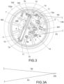
- the tubular jacket 4 again as shown in the section of figure 3 or in figure 5 , comprises, at the first end 1a, a slot 6, which extends for at least one section along the longitudinal axis T-T.
- the jacket 4 is shaped to contain the shock absorber group 7 in the space 5 ( Fig. 3 ).
- the shock absorber group 7 comprises a damper 71, functionally coupled to a spring 72, both contained in the space 5.
- the space 5 houses only the damper 71 while the spring 72, functionally coupled to the latter, is disposed on the outside.
- the damper 71 and the spring 72 coupled together, define a fixed base portion 7a, fitted by means of a threaded connection to the jacket 4, and a movable head portion 7b opposite to the fixed portion 7a.
- the moving head portion 7b is adapted to slide within the space 5 of the jacket 4, according to the longitudinal axis T-T.
- the support arm 8 comprises a guide rod 11 which extends from the support arm 8 and is keyed with the moving head portion 7b of the shock absorber group 7.
- the guide rod 11 moves in the slot 6, which defines the travel thereof, following the sussultatory movements of the shock absorber group 7, transmitted by the wheel 102,102a.
- the guide rod 11 is found at the first end 1a.
- the guide rod 11 moves towards the second end 1b, as described in detail below.
- the second crank 12 guides the translation of the movable head portion 7b along said tubular jacket 4 along a sliding direction substantially coaxial to said longitudinal axis T-T.
- the second crank 12 has the driving function; in other words, it allows the shock absorber group 7 to move coaxially to the tubular jacket, i.e. coaxially to the longitudinal axis T-T which represents the suspension axis.
- the configuration of the quadrilateral suspension ensures a better control of the wheel trajectory fixed to the wheel guide of the shock absorber, as well as greater strength and therefore reliability.
- the first crank 9 - positioned below - acts as a support especially in the transverse direction
- the second crank 12 - positioned above - acts as a guide for the trajectory and reaction to the braking force which is discharged on the wheel guide 1.
- the second crank 12 has a dimensional ratio with respect to the first crank 9 which defines a configuration of the suspension quadrilateral such that the instantaneous center of rotation converges substantially to infinity, or in another configuration - as shown schematically in figure 3 and 3A - an instantaneous center of rotation CR converging in a finite point from the side external to the support arm 8.
- the instantaneous center of rotation CR is defined by a first straight line R1 passing through the first 9a and the second hinge 9b of the first crank 9, and by a second line R2 passing through the third hinge 12a and the fourth hinge 12b of the second crank 12.
- Figure 3A shows the intersection point of the lines R1 and R2 shown in figure 3 , i.e. the instantaneous center of rotation CR of the suspension.
- the second crank 12 is a flatly shaped element provided with respective holes passing through the ends corresponding to the attachment hinges 12a, 12b with the support arm 8 and the wheel guide 1. At least one bearing or bushing is inserted in the through holes, on which a respective pin 12c ( Fig.5 ), 12d ( Fig.3 ) is keyed.
- the third hinge 12a comprises an attachment portion formed on the support arm 8 which extends as a branch 8a thereof.
- the attachment portion 8a has a "U" shape with opposing side attachment walls 8b opposite each other, so that the end of the second crank 12 is contained between the attachment walls 8b and the associated pin 12c is functionally supported by the side walls 8b.
- the first crank 9 consists of two distinct elements 9,9' parallel to each other which couple with the support arm 8 and the wheel guide 1 at the first 9a and second 9b hinge on opposite sides, the one from the other.
- braking means 154,155 for example a caliper 154 for a disk brake 155, of the corresponding wheel are fixed to each wheel guide 1.
- the braking means 154, 155 may be of any type; preferably, said braking means 154, 155 are positioned and sized so as to enter within the volume 180 delimited by the rim 184 of each wheel 102,102a ( Fig. 3 ).
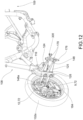
- the wheel guide 1 comprises special eyelets 157 ( Fig.4 ) formed on the jacket 4, to allow the fixing of the brake caliper 154 to the wheel guide 1.
- the suspension group 10 described above is applied to each wheel group 102, 102a of the front end 108 of the three-wheeled motorcycle 100 of figure 2a , as described below.
- the suspension group 10 is entirely contained within a volume 180 delimited by a rim 184 of each wheel 102,102a ( Fig.3 ).
- the suspension groups 10 of the front wheels 102 and 102a face each other from the inside of the respective wheel ( Fig.2 ). In other words, the suspension groups 10 are turned toward the centerline plane M-M of the three wheel motorcycle, and the related components associated with the stub axle are not directly visible to an external observer.
- the support arm 8 comprises a support upright 148,148a.
- the support upright 148,148a is integrated inside the support arm 8 and extends between the first end 1a and the second end 1b.
- the support upright 148,148a defines a branch of an articulated quadrilateral 120 and is bound to the latter by means of respective steering hinges 176.
- the steering hinges 176 define respective steering axes S-S of the wheels 102,102a, parallel to one another.
- the articulated quadrilateral 120 further comprises an upper cross member 124 and a lower cross member 125.
- the pair of cross members 124 and 125 are hinged to the front end chassis 116 at middle hinges 128. ( Fig.2 ) Furthermore, the cross members 124 and 125 are connected to the corresponding ends by means of corresponding rolling hinges 178.
- the articulated suspension quadrilateral of the suspension group 10 may rotate about axes of the respective support uprights 148, 148a to allow the steering of the three wheel motorcycle.
- Said articulated suspension quadrilaterals are placed in rotation through a rod (single or articulated) 300, which is hinged at a preferably spherical hinge 301 with the support arm 8.
- Said rod 300 is then functionally connected to the steering of the three wheel motorcycle to actuate the steering.
- the rolling of the three wheel motorcycle is therefore determined by the rolling quadrilateral 120, while the steering is permitted by the rotation of the suspension quadrilateral with respect to the rolling quadrilateral 120, about said axes of the support uprights 148, 148a, also called steering hinges 176.
- the present invention overcomes the disadvantages of the prior art.
- the present invention improves the dynamic behavior of the vehicle and improves the reliability of the suspension making it simpler constructively, with respect to the solutions of the prior art.
- a suspension group 10 for a three wheel motorcycle 100 according to present invention wherein the wheel guide 1 comprises a tubular jacket 4 which defines a housing space 5, wherein the shock absorber group 7 is housed at least partially in said housing space 5.
Landscapes
- Engineering & Computer Science (AREA)
- Mechanical Engineering (AREA)
- Vehicle Body Suspensions (AREA)
- Arrangement Or Mounting Of Propulsion Units For Vehicles (AREA)
- Axle Suspensions And Sidecars For Cycles (AREA)
- Automatic Cycles, And Cycles In General (AREA)
Applications Claiming Priority (2)
| Application Number | Priority Date | Filing Date | Title |
|---|---|---|---|
| IT102016000124367A IT201600124367A1 (it) | 2016-12-07 | 2016-12-07 | Gruppo sospensione per motoveicolo, gruppo ruota per motoveicolo, avantreno di motoveicolo e relativo motoveicolo |
| PCT/IB2017/057729 WO2018104906A1 (en) | 2016-12-07 | 2017-12-07 | Suspension group for motor vehicle, wheel group for motor vehicle, front end of a motor vehicle and motor vehicle thereof |
Publications (3)
| Publication Number | Publication Date |
|---|---|
| EP3551528A1 EP3551528A1 (en) | 2019-10-16 |
| EP3551528B1 true EP3551528B1 (en) | 2023-09-13 |
| EP3551528C0 EP3551528C0 (en) | 2023-09-13 |
Family
ID=58455472
Family Applications (1)
| Application Number | Title | Priority Date | Filing Date |
|---|---|---|---|
| EP17826287.9A Active EP3551528B1 (en) | 2016-12-07 | 2017-12-07 | Suspension group for motor vehicle, wheel group for motor vehicle, front end of a motor vehicle and motor vehicle thereof |
Country Status (9)
| Country | Link |
|---|---|
| US (1) | US11046134B2 (es) |
| EP (1) | EP3551528B1 (es) |
| JP (1) | JP6971317B2 (es) |
| CN (1) | CN110177737B (es) |
| ES (1) | ES2962153T3 (es) |
| IL (1) | IL266852B2 (es) |
| IT (1) | IT201600124367A1 (es) |
| MX (1) | MX2019006407A (es) |
| WO (1) | WO2018104906A1 (es) |
Families Citing this family (7)
| Publication number | Priority date | Publication date | Assignee | Title |
|---|---|---|---|---|
| IT201800010942A1 (it) | 2018-12-10 | 2020-06-10 | Piaggio & C Spa | Avantreno per veicolo a due ruote anteriori sterzanti e motoveicolo comprendente detto avantreno |
| CN114025972B (zh) * | 2019-06-28 | 2023-04-21 | 瑞翼汽车有限公司 | 用于双臂悬架和轮内转向的装置和方法 |
| IT201900015911A1 (it) * | 2019-09-09 | 2021-03-09 | Piaggio & C Spa | Un motoveicolo con una sospensione impiegante un quadrilatero articolato di roberts |
| IT201900015908A1 (it) * | 2019-09-09 | 2021-03-09 | Piaggio & C Spa | Un motoveicolo con una sospensione impiegante un quadrilatero articolato di tchebicheff |
| IT202100015341A1 (it) | 2021-06-11 | 2022-12-11 | Piaggio & C Spa | Veicolo rollante a sella cavalcabile con carenatura all’avantreno non rollante. |
| IT202100015359A1 (it) | 2021-06-11 | 2022-12-11 | Piaggio & C Spa | Veicolo rollante a sella cavalcabile con capacita’ di carico nella parte di avantreno. |
| IT202100022853A1 (it) | 2021-09-03 | 2023-03-03 | Floris Alessandra | Un veicolo a tre o quattro ruote tiltante con parallelogramma orizzontale |
Citations (1)
| Publication number | Priority date | Publication date | Assignee | Title |
|---|---|---|---|---|
| JP2007062605A (ja) * | 2005-08-31 | 2007-03-15 | Toyota Motor Corp | インホイールサスペンション |
Family Cites Families (43)
| Publication number | Priority date | Publication date | Assignee | Title |
|---|---|---|---|---|
| US1093131A (en) * | 1912-02-16 | 1914-04-14 | Charles Lepley Hays | Load-supporting means for carrying-wheels. |
| GB163504A (en) * | 1920-02-25 | 1921-05-25 | Harry Topham Short | Improvements in or relating to spring forks for cycles and motor cycles |
| US2044232A (en) * | 1933-12-01 | 1936-06-16 | Briggs Mfg Co | Wheel suspension and steering mechanism |
| US2689747A (en) * | 1951-02-09 | 1954-09-21 | Kolbe Joachim | Vehicle with variable length banking links |
| US4088199A (en) * | 1976-02-23 | 1978-05-09 | Wolfgang Trautwein | Stabilized three-wheeled vehicle |
| IT1124375B (it) | 1979-12-07 | 1986-05-07 | Valentino Ribi | Sospensione a quadrilatero articolato con almeno un ammortizzatore per ruote di autoveicoli in particolare di motocilette |
| JPS57107979A (en) | 1980-12-25 | 1982-07-05 | Honda Motor Co Ltd | Suspension system for front wheel of autobicycle |
| US4515390A (en) * | 1983-04-11 | 1985-05-07 | Greenberg William H | Chassis and suspension system for vehicles |
| JPS6192983A (ja) * | 1985-09-13 | 1986-05-10 | 本田技研工業株式会社 | 自動二輪車の前輪懸架装置 |
| US5580089A (en) * | 1994-10-11 | 1996-12-03 | Kolka; David B. | Vehicle stabilization system and method |
| DE29519108U1 (de) * | 1995-12-05 | 1997-04-03 | Kramer Klaus | Radaufhängungsvorrichtung zur Führung eines gefederten Laufrades |
| AR001418A1 (es) | 1996-03-25 | 1997-10-22 | Osvaldo Amilcar Maestripieri | Cuadro elástico para bicicletas (ciclomotor o motos). |
| DE19717418C1 (de) * | 1997-04-25 | 1998-10-22 | Daimler Benz Ag | Mehrspuriges Kurvenneigerfahrzeug |
| US6260869B1 (en) * | 1997-07-31 | 2001-07-17 | Excelsior-Henderson Motorcyle Co. | Motorcycle front suspension system |
| FR2796594A1 (fr) * | 1999-07-23 | 2001-01-26 | Michelin & Cie | Vehicule automobile equipe d'un systeme de controle de l'angle de carrossage des roues du vehicule en virage |
| US6311795B1 (en) * | 2000-05-02 | 2001-11-06 | Case Corporation | Work vehicle steering and suspension system |
| ITPN20000034A1 (it) * | 2000-06-02 | 2001-12-02 | Aprilia Spa | Perfezionamenti ai veicoli aventi due ruote anteriori rollanti e sterzanti e almeno una ruota motrice posteriore |
| ATE380689T1 (de) * | 2001-01-23 | 2007-12-15 | Michelin Soc Tech | Aufhängungsvorrichtung für ein kraftfahrzeugrad |
| US6722994B2 (en) * | 2001-03-09 | 2004-04-20 | Deer & Co. | Suspended drive axle and agricultural tractor with same |
| JP2004352121A (ja) * | 2003-05-29 | 2004-12-16 | Aruze Corp | 前輪支持機構 |
| JP4305429B2 (ja) * | 2005-08-18 | 2009-07-29 | トヨタ自動車株式会社 | インホイールサスペンション |
| JP4258514B2 (ja) * | 2005-10-27 | 2009-04-30 | トヨタ自動車株式会社 | インホイールサスペンション |
| JP4694451B2 (ja) * | 2006-09-26 | 2011-06-08 | 本田技研工業株式会社 | 前輪懸架装置 |
| WO2009126787A2 (en) * | 2008-04-10 | 2009-10-15 | Sacli Suspension, Llc | Suspension system providing two degrees of freedom |
| CN101670757B (zh) * | 2009-10-22 | 2011-09-28 | 浙江吉利汽车研究院有限公司 | 一种用于双体车的前悬架 |
| KR101165895B1 (ko) * | 2010-04-15 | 2012-07-13 | 진성현 | 삼륜차의 현가장치 |
| CN202557707U (zh) * | 2012-04-28 | 2012-11-28 | 厦门坤骑复材科技有限公司 | 一种自行车避震车架 |
| JP2014015063A (ja) * | 2012-07-05 | 2014-01-30 | Nhk Spring Co Ltd | 車両懸架装置 |
| JP6112934B2 (ja) * | 2013-03-28 | 2017-04-12 | 本田技研工業株式会社 | 前二輪式鞍乗り型揺動車両 |
| ITPD20130136A1 (it) * | 2013-05-16 | 2014-11-17 | Piaggio & C Spa | Sospensione motociclistica |
| WO2015151064A1 (en) * | 2014-04-02 | 2015-10-08 | Iveco S.P.A. | Double wishbone or mcpherson suspension with transverse leaf spring and dimensioning method thereof |
| CN105313628A (zh) * | 2014-08-04 | 2016-02-10 | 朱玉根 | 带液压减震装置的汽车车轮悬架结构 |
| ITUB20152758A1 (it) * | 2015-08-03 | 2017-02-03 | Piaggio & C Spa | Sospensione per ruota di motoveicolo, gruppo ruota di motoveicolo, avantreno di motoveicolo e relativo motoveicolo |
| ITUB20152766A1 (it) | 2015-08-03 | 2017-02-03 | Piaggio & C Spa | Avantreno di motoveicolo tiltante e relativo motoveicolo |
| JP6148305B2 (ja) | 2015-09-30 | 2017-06-14 | 本田技研工業株式会社 | 鞍乗り型車両 |
| CN205439856U (zh) | 2016-04-02 | 2016-08-10 | 上海海洋大学 | 一种动蹼明轮式两栖车行走机构 |
| CN205439858U (zh) * | 2016-04-14 | 2016-08-10 | 韦伟 | 一种老年车高效减震机构 |
| CN106114103A (zh) * | 2016-07-20 | 2016-11-16 | 浙江大学昆山创新中心 | 一种用于轮式移动机器人的多连杆悬挂系统 |
| IT201600116483A1 (it) * | 2016-11-17 | 2018-05-17 | Piaggio & C Spa | Sospensione anteriore di tipo telescopico con effetto anti-affondamento |
| IT201600129497A1 (it) * | 2016-12-21 | 2018-06-21 | Piaggio & C Spa | Avantreno di motoveicolo rollante con blocco di rollio |
| IT201600129510A1 (it) * | 2016-12-21 | 2018-06-21 | Piaggio & C Spa | Avantreno di motoveicolo rollante con controllo di rollio |
| IT201800004941A1 (it) * | 2018-04-27 | 2019-10-27 | Sospensione motociclistica anteriore | |
| US10723191B1 (en) * | 2018-07-01 | 2020-07-28 | Softwheel Ltd. | In-wheel three-arm suspension for vehicles |
-
2016
- 2016-12-07 IT IT102016000124367A patent/IT201600124367A1/it unknown
-
2017
- 2017-12-07 US US16/465,163 patent/US11046134B2/en active Active
- 2017-12-07 EP EP17826287.9A patent/EP3551528B1/en active Active
- 2017-12-07 MX MX2019006407A patent/MX2019006407A/es unknown
- 2017-12-07 ES ES17826287T patent/ES2962153T3/es active Active
- 2017-12-07 WO PCT/IB2017/057729 patent/WO2018104906A1/en unknown
- 2017-12-07 CN CN201780075567.7A patent/CN110177737B/zh active Active
- 2017-12-07 JP JP2019528917A patent/JP6971317B2/ja active Active
-
2019
- 2019-05-23 IL IL266852A patent/IL266852B2/en unknown
Patent Citations (1)
| Publication number | Priority date | Publication date | Assignee | Title |
|---|---|---|---|---|
| JP2007062605A (ja) * | 2005-08-31 | 2007-03-15 | Toyota Motor Corp | インホイールサスペンション |
Also Published As
| Publication number | Publication date |
|---|---|
| IL266852A (en) | 2019-07-31 |
| US20190329616A1 (en) | 2019-10-31 |
| JP2020513369A (ja) | 2020-05-14 |
| IT201600124367A1 (it) | 2018-06-07 |
| US11046134B2 (en) | 2021-06-29 |
| WO2018104906A1 (en) | 2018-06-14 |
| CN110177737A (zh) | 2019-08-27 |
| IL266852B2 (en) | 2023-02-01 |
| MX2019006407A (es) | 2019-09-04 |
| JP6971317B2 (ja) | 2021-11-24 |
| IL266852B (en) | 2022-10-01 |
| ES2962153T3 (es) | 2024-03-15 |
| EP3551528A1 (en) | 2019-10-16 |
| EP3551528C0 (en) | 2023-09-13 |
| CN110177737B (zh) | 2021-04-06 |
Similar Documents
| Publication | Publication Date | Title |
|---|---|---|
| EP3551528B1 (en) | Suspension group for motor vehicle, wheel group for motor vehicle, front end of a motor vehicle and motor vehicle thereof | |
| CN109476355B (zh) | 带反应式约束悬架的具有三个或更多个倾斜的车轮的车辆 | |
| CA2901402C (en) | Suspension assembly for a utility vehicle | |
| CN108136865B (zh) | 机动车辆轮悬挂装置、轮组件、前轮架及机动车辆 | |
| CN108473176B (zh) | 机动车辆的前叉 | |
| JP6091790B2 (ja) | 能動制御懸架装置 | |
| CA3104456A1 (en) | In-wheel three-arm suspension for vehicles | |
| EP3870504B1 (en) | A motor vehicle with two front steered wheels and a four-bar linkage containing two suspensions | |
| US8596647B2 (en) | Active roll control system | |
| EP3894311B1 (en) | Forecarriage for two front steered wheel vehicle and motor vehicle including said forecarriage | |
| CN114364550A (zh) | 具有使用瓦特四连杆机构的悬架的机动车辆 | |
| JPH01190511A (ja) | 車両のサスペンション装置 | |
| EP4028315B1 (en) | A motor vehicle with a suspension using a tchebicheff four-bar linkage | |
| TWI732095B (zh) | 機動車輛及其懸吊組、車輪組、前端總成 | |
| JP4857658B2 (ja) | サスペンション装置 | |
| RU2225796C2 (ru) | Независимая подвеска управляемых колес автомобиля | |
| KR101836530B1 (ko) | 차량용 푸셔액슬의 조향장치 | |
| RU2509657C2 (ru) | Подвеска транспортного средства |
Legal Events
| Date | Code | Title | Description |
|---|---|---|---|
| STAA | Information on the status of an ep patent application or granted ep patent |
Free format text: STATUS: UNKNOWN |
|
| STAA | Information on the status of an ep patent application or granted ep patent |
Free format text: STATUS: THE INTERNATIONAL PUBLICATION HAS BEEN MADE |
|
| PUAI | Public reference made under article 153(3) epc to a published international application that has entered the european phase |
Free format text: ORIGINAL CODE: 0009012 |
|
| STAA | Information on the status of an ep patent application or granted ep patent |
Free format text: STATUS: REQUEST FOR EXAMINATION WAS MADE |
|
| 17P | Request for examination filed |
Effective date: 20190523 |
|
| AK | Designated contracting states |
Kind code of ref document: A1 Designated state(s): AL AT BE BG CH CY CZ DE DK EE ES FI FR GB GR HR HU IE IS IT LI LT LU LV MC MK MT NL NO PL PT RO RS SE SI SK SM TR |
|
| AX | Request for extension of the european patent |
Extension state: BA ME |
|
| DAV | Request for validation of the european patent (deleted) | ||
| DAX | Request for extension of the european patent (deleted) | ||
| STAA | Information on the status of an ep patent application or granted ep patent |
Free format text: STATUS: EXAMINATION IS IN PROGRESS |
|
| 17Q | First examination report despatched |
Effective date: 20200827 |
|
| STAA | Information on the status of an ep patent application or granted ep patent |
Free format text: STATUS: EXAMINATION IS IN PROGRESS |
|
| STAA | Information on the status of an ep patent application or granted ep patent |
Free format text: STATUS: EXAMINATION IS IN PROGRESS |
|
| GRAP | Despatch of communication of intention to grant a patent |
Free format text: ORIGINAL CODE: EPIDOSNIGR1 |
|
| STAA | Information on the status of an ep patent application or granted ep patent |
Free format text: STATUS: GRANT OF PATENT IS INTENDED |
|
| RIC1 | Information provided on ipc code assigned before grant |
Ipc: B60G 3/20 20060101ALI20230308BHEP Ipc: B60G 3/18 20060101ALI20230308BHEP Ipc: B60G 3/01 20060101ALI20230308BHEP Ipc: B62K 25/00 20060101ALI20230308BHEP Ipc: B62K 5/10 20130101ALI20230308BHEP Ipc: B62K 5/08 20060101ALI20230308BHEP Ipc: B62K 5/027 20130101AFI20230308BHEP |
|
| INTG | Intention to grant announced |
Effective date: 20230412 |
|
| GRAS | Grant fee paid |
Free format text: ORIGINAL CODE: EPIDOSNIGR3 |
|
| GRAA | (expected) grant |
Free format text: ORIGINAL CODE: 0009210 |
|
| STAA | Information on the status of an ep patent application or granted ep patent |
Free format text: STATUS: THE PATENT HAS BEEN GRANTED |
|
| AK | Designated contracting states |
Kind code of ref document: B1 Designated state(s): AL AT BE BG CH CY CZ DE DK EE ES FI FR GB GR HR HU IE IS IT LI LT LU LV MC MK MT NL NO PL PT RO RS SE SI SK SM TR |
|
| REG | Reference to a national code |
Ref country code: GB Ref legal event code: FG4D |
|
| REG | Reference to a national code |
Ref country code: CH Ref legal event code: EP |
|
| REG | Reference to a national code |
Ref country code: DE Ref legal event code: R096 Ref document number: 602017074242 Country of ref document: DE |
|
| REG | Reference to a national code |
Ref country code: IE Ref legal event code: FG4D |
|
| U01 | Request for unitary effect filed |
Effective date: 20230929 |
|
| U07 | Unitary effect registered |
Designated state(s): AT BE BG DE DK EE FI FR IT LT LU LV MT NL PT SE SI Effective date: 20231011 |
|
| U20 | Renewal fee paid [unitary effect] |
Year of fee payment: 7 Effective date: 20231123 |
|
| PG25 | Lapsed in a contracting state [announced via postgrant information from national office to epo] |
Ref country code: GR Free format text: LAPSE BECAUSE OF FAILURE TO SUBMIT A TRANSLATION OF THE DESCRIPTION OR TO PAY THE FEE WITHIN THE PRESCRIBED TIME-LIMIT Effective date: 20231214 |
|
| PGFP | Annual fee paid to national office [announced via postgrant information from national office to epo] |
Ref country code: GB Payment date: 20231220 Year of fee payment: 7 |
|
| PG25 | Lapsed in a contracting state [announced via postgrant information from national office to epo] |
Ref country code: RS Free format text: LAPSE BECAUSE OF FAILURE TO SUBMIT A TRANSLATION OF THE DESCRIPTION OR TO PAY THE FEE WITHIN THE PRESCRIBED TIME-LIMIT Effective date: 20230913 Ref country code: NO Free format text: LAPSE BECAUSE OF FAILURE TO SUBMIT A TRANSLATION OF THE DESCRIPTION OR TO PAY THE FEE WITHIN THE PRESCRIBED TIME-LIMIT Effective date: 20231213 Ref country code: HR Free format text: LAPSE BECAUSE OF FAILURE TO SUBMIT A TRANSLATION OF THE DESCRIPTION OR TO PAY THE FEE WITHIN THE PRESCRIBED TIME-LIMIT Effective date: 20230913 Ref country code: GR Free format text: LAPSE BECAUSE OF FAILURE TO SUBMIT A TRANSLATION OF THE DESCRIPTION OR TO PAY THE FEE WITHIN THE PRESCRIBED TIME-LIMIT Effective date: 20231214 |
|
| REG | Reference to a national code |
Ref country code: ES Ref legal event code: FG2A Ref document number: 2962153 Country of ref document: ES Kind code of ref document: T3 Effective date: 20240315 |
|
| PG25 | Lapsed in a contracting state [announced via postgrant information from national office to epo] |
Ref country code: IS Free format text: LAPSE BECAUSE OF FAILURE TO SUBMIT A TRANSLATION OF THE DESCRIPTION OR TO PAY THE FEE WITHIN THE PRESCRIBED TIME-LIMIT Effective date: 20240113 |
|
| PGFP | Annual fee paid to national office [announced via postgrant information from national office to epo] |
Ref country code: ES Payment date: 20240102 Year of fee payment: 7 |
|
| PG25 | Lapsed in a contracting state [announced via postgrant information from national office to epo] |
Ref country code: SM Free format text: LAPSE BECAUSE OF FAILURE TO SUBMIT A TRANSLATION OF THE DESCRIPTION OR TO PAY THE FEE WITHIN THE PRESCRIBED TIME-LIMIT Effective date: 20230913 Ref country code: RO Free format text: LAPSE BECAUSE OF FAILURE TO SUBMIT A TRANSLATION OF THE DESCRIPTION OR TO PAY THE FEE WITHIN THE PRESCRIBED TIME-LIMIT Effective date: 20230913 Ref country code: IS Free format text: LAPSE BECAUSE OF FAILURE TO SUBMIT A TRANSLATION OF THE DESCRIPTION OR TO PAY THE FEE WITHIN THE PRESCRIBED TIME-LIMIT Effective date: 20240113 Ref country code: CZ Free format text: LAPSE BECAUSE OF FAILURE TO SUBMIT A TRANSLATION OF THE DESCRIPTION OR TO PAY THE FEE WITHIN THE PRESCRIBED TIME-LIMIT Effective date: 20230913 Ref country code: SK Free format text: LAPSE BECAUSE OF FAILURE TO SUBMIT A TRANSLATION OF THE DESCRIPTION OR TO PAY THE FEE WITHIN THE PRESCRIBED TIME-LIMIT Effective date: 20230913 |