EP3527743B1 - Mechanisches arretierungssystem für bodenplatten - Google Patents
Mechanisches arretierungssystem für bodenplatten Download PDFInfo
- Publication number
- EP3527743B1 EP3527743B1 EP19167121.3A EP19167121A EP3527743B1 EP 3527743 B1 EP3527743 B1 EP 3527743B1 EP 19167121 A EP19167121 A EP 19167121A EP 3527743 B1 EP3527743 B1 EP 3527743B1
- Authority
- EP
- European Patent Office
- Prior art keywords
- locking
- edge
- panel
- tongue
- clip
- Prior art date
- Legal status (The legal status is an assumption and is not a legal conclusion. Google has not performed a legal analysis and makes no representation as to the accuracy of the status listed.)
- Active
Links
- 239000000463 material Substances 0.000 claims description 18
- 239000004033 plastic Substances 0.000 claims description 8
- 229920003023 plastic Polymers 0.000 claims description 8
- 239000012815 thermoplastic material Substances 0.000 claims description 3
- 239000011162 core material Substances 0.000 description 27
- 239000010410 layer Substances 0.000 description 11
- 239000012792 core layer Substances 0.000 description 7
- 238000009408 flooring Methods 0.000 description 7
- 229910052751 metal Inorganic materials 0.000 description 5
- 239000002184 metal Substances 0.000 description 5
- 238000000926 separation method Methods 0.000 description 5
- 239000004411 aluminium Substances 0.000 description 4
- 229910052782 aluminium Inorganic materials 0.000 description 4
- XAGFODPZIPBFFR-UHFFFAOYSA-N aluminium Chemical compound [Al] XAGFODPZIPBFFR-UHFFFAOYSA-N 0.000 description 4
- 238000009434 installation Methods 0.000 description 4
- 238000000034 method Methods 0.000 description 4
- 238000005452 bending Methods 0.000 description 3
- 238000007667 floating Methods 0.000 description 3
- 239000003292 glue Substances 0.000 description 3
- 238000004519 manufacturing process Methods 0.000 description 3
- 238000003825 pressing Methods 0.000 description 3
- 239000002344 surface layer Substances 0.000 description 3
- 238000004026 adhesive bonding Methods 0.000 description 2
- 238000010420 art technique Methods 0.000 description 2
- 238000006073 displacement reaction Methods 0.000 description 2
- 239000000945 filler Substances 0.000 description 2
- 239000011888 foil Substances 0.000 description 2
- 239000003365 glass fiber Substances 0.000 description 2
- 238000005304 joining Methods 0.000 description 2
- 239000004922 lacquer Substances 0.000 description 2
- 238000004080 punching Methods 0.000 description 2
- 229920001169 thermoplastic Polymers 0.000 description 2
- 229920001187 thermosetting polymer Polymers 0.000 description 2
- 239000004416 thermosoftening plastic Substances 0.000 description 2
- 239000002023 wood Substances 0.000 description 2
- 229910000831 Steel Inorganic materials 0.000 description 1
- 229920002522 Wood fibre Polymers 0.000 description 1
- 239000000919 ceramic Substances 0.000 description 1
- 230000000694 effects Effects 0.000 description 1
- 238000005516 engineering process Methods 0.000 description 1
- 239000000835 fiber Substances 0.000 description 1
- 238000003754 machining Methods 0.000 description 1
- 239000000203 mixture Substances 0.000 description 1
- 230000000149 penetrating effect Effects 0.000 description 1
- 230000035515 penetration Effects 0.000 description 1
- 239000000843 powder Substances 0.000 description 1
- 238000007789 sealing Methods 0.000 description 1
- 239000010959 steel Substances 0.000 description 1
- 125000000391 vinyl group Chemical group [H]C([*])=C([H])[H] 0.000 description 1
- 229920002554 vinyl polymer Polymers 0.000 description 1
Images


Classifications
-
- E—FIXED CONSTRUCTIONS
- E04—BUILDING
- E04F—FINISHING WORK ON BUILDINGS, e.g. STAIRS, FLOORS
- E04F15/00—Flooring
- E04F15/02—Flooring or floor layers composed of a number of similar elements
- E04F15/02038—Flooring or floor layers composed of a number of similar elements characterised by tongue and groove connections between neighbouring flooring elements
-
- E—FIXED CONSTRUCTIONS
- E04—BUILDING
- E04F—FINISHING WORK ON BUILDINGS, e.g. STAIRS, FLOORS
- E04F15/00—Flooring
- E04F15/02—Flooring or floor layers composed of a number of similar elements
- E04F15/10—Flooring or floor layers composed of a number of similar elements of other materials, e.g. fibrous or chipped materials, organic plastics, magnesite tiles, hardboard, or with a top layer of other materials
- E04F15/105—Flooring or floor layers composed of a number of similar elements of other materials, e.g. fibrous or chipped materials, organic plastics, magnesite tiles, hardboard, or with a top layer of other materials of organic plastics with or without reinforcements or filling materials
-
- E—FIXED CONSTRUCTIONS
- E04—BUILDING
- E04F—FINISHING WORK ON BUILDINGS, e.g. STAIRS, FLOORS
- E04F15/00—Flooring
- E04F15/02—Flooring or floor layers composed of a number of similar elements
- E04F15/10—Flooring or floor layers composed of a number of similar elements of other materials, e.g. fibrous or chipped materials, organic plastics, magnesite tiles, hardboard, or with a top layer of other materials
- E04F15/107—Flooring or floor layers composed of a number of similar elements of other materials, e.g. fibrous or chipped materials, organic plastics, magnesite tiles, hardboard, or with a top layer of other materials composed of several layers, e.g. sandwich panels
-
- E—FIXED CONSTRUCTIONS
- E04—BUILDING
- E04F—FINISHING WORK ON BUILDINGS, e.g. STAIRS, FLOORS
- E04F2201/00—Joining sheets or plates or panels
- E04F2201/01—Joining sheets, plates or panels with edges in abutting relationship
- E04F2201/0153—Joining sheets, plates or panels with edges in abutting relationship by rotating the sheets, plates or panels around an axis which is parallel to the abutting edges, possibly combined with a sliding movement
- E04F2201/0161—Joining sheets, plates or panels with edges in abutting relationship by rotating the sheets, plates or panels around an axis which is parallel to the abutting edges, possibly combined with a sliding movement with snap action of the edge connectors
-
- E—FIXED CONSTRUCTIONS
- E04—BUILDING
- E04F—FINISHING WORK ON BUILDINGS, e.g. STAIRS, FLOORS
- E04F2201/00—Joining sheets or plates or panels
- E04F2201/04—Other details of tongues or grooves
- E04F2201/041—Tongues or grooves with slits or cuts for expansion or flexibility
-
- E—FIXED CONSTRUCTIONS
- E04—BUILDING
- E04F—FINISHING WORK ON BUILDINGS, e.g. STAIRS, FLOORS
- E04F2201/00—Joining sheets or plates or panels
- E04F2201/05—Separate connectors or inserts, e.g. pegs, pins, keys or strips
- E04F2201/0517—U- or C-shaped brackets and clamps
Definitions
- the disclosure generally relates to the field of mechanical locking systems for floor panels and building panels.
- the disclosure shows floorboards, locking systems and production methods.
- the present invention is particularly suitable for use in thin floating floors, which are formed of floor panels which are joined mechanically with a locking system preferably integrated with the floor panel, i.e. mounted at the factory, are made up of one or more upper layers of thermoplastic or thermosetting material or wood veneer, an intermediate core of wood-fibre-based material or plastic material and preferably a lower balancing layer on the rear side of the core.
- the invention can also be used for joining building panels which preferably contain a board material for instance wall panels, ceilings, furniture components and similar. Parts of the locking system may also be supplied as separate components, which may be connected to a panel during installation.
- the long and short edges are mainly used to simplify the description of the invention.
- the panels may be square. It should be emphasised that the invention can be used in any floor panel on long and/or short edges and it may be combined with all types of known locking system that lock the panels in the horizontal and/or vertical direction.
- LVT flooring usually comprises a transparent wear layer which may be coated by a UV cured PU lacquer, a decorative plastic foil and one or several core layers which generally are of different density and hardness. Relevant parts of this prior art description are also a part of the invention.
- LVT floors with a thickness of 2-3 mm have traditionally been installed by gluing to the sub floor.
- LVT floors have been introduced on the market that comprises a mechanical locking system, which allows a floating installation without glue. This facilitates installation and eliminates a lot of work to prepare the sub floor for gluing.
- Such LVT floors have generally a thickness of about 5 mm. This thickness is mainly required in order to form the locking system.
- the panel itself is strong and flexible and a thickness of about 3 mm would in many application be sufficient but can not be used since it is not possible to form a strong and cost efficient locking system in such thin floors.
- Such problems related to minimum thickness requirements due to the forming of locking systems are also applicable in other thin floor panels such as laminate floors and wood powder based floors where material and weight savings may be accomplished with lower thicknesses, preferably below 6 mm.
- Laminate flooring usually comprise a core of a 6-12 mm fibre board, a 0.2-0.8 mm thick upper decorative surface layer of laminate and a 0.1-0.6 mm thick lower balancing layer of laminate, plastic, paper or like material.
- a laminate surface comprises melamine-impregnated paper.
- the most common core material is fibreboard with high density and good stability usually called HDF - High Density Fibreboard. Sometimes also MDF - Medium Density Fibreboard - is used as core.
- Laminate floor panels of this type have been joined mechanically by means of so-called mechanical locking systems. These systems comprise locking means, which lock the panels horizontally and vertically.
- the mechanical locking systems are usually formed by machining of the core of the panel.
- parts of the locking system can be formed of a separate material, for instance aluminium or HDF, which are integrated with the floor panel, i.e. joined with the floor panel in connection with the manufacture thereof.
- front side the visible surface of the installed floor panel
- rear side the opposite side of the floor panel, facing the sub floor
- the edge between the front and rear side is called “joint edge”.
- horizontal plane is meant a plane, which extends parallel to the front side.
- Immediately juxtaposed upper parts of two adjacent joint edges of two joined floor panels together define a “vertical plane” perpendicular to the horizontal plane.
- vertical locking is meant locking parallel to the vertical plane.
- horizontal locking is meant locking parallel to the horizontal plane.
- up is meant towards the front side, by “down” towards the rear side, by “inwardly” mainly horizontally towards an inner and centre part of the panel and by “outwardly” mainly horizontally away from the centre part of the panel.
- the long edges are installed by angling.
- the short edges are locked by horizontal snapping.
- the vertical connection is generally a tongue and a groove and the horizontal connection is a strip with a locking element that cooperates with a locking groove in the adjacent edge.
- Similar locking systems may also be produced with a rigid strip and they are connected with an angling-angling method where both short and long edges are angled into a locked position.
- a locking strip may be formed of a separate material such as aluminium and that such strip may be clamped in undercut grooves. Such systems are described in WO94/26999 .
- the separate metal strip may be used to lock very thin panes with a thickness of about 3 mm provided that the core is made of a strong material for example compact laminate or a high quality HDF and that the strip extends along essentially the whole edge.
- the strip is used to accomplish vertical and horizontal locking.
- WO 99/66152 describes a locking system with a tongue and a tongue groove and a separate metal strip that is attached to the lower lip of the tongue groove and that in locked position is located vertically under the tongue.
- Such locking system is not suitable for thin flooring since the thickness must be sufficient to form the tongue groove and a connecting part for the strip under the groove.
- 1/3 of the panel thickens is used to form the upper lip, 1/3 is used to form the tongue and 1/3 remains to form the lower lip,
- the available material thickness that may be used to form the strip under the tongue is generally less than 1/3 of the panel thickness.
- a connection to the outer part of the lower lip is also disadvantage in panels with a soft and flexible core such as LVT.
- a lower lip formed in soft and flexible material bends downwards when the strip is exposed to rather low separation forces and a strong strip will not improve the locking strength due to inferior connection to the panel edge.
- clips may be used to accomplish horizontal and vertical locking. Such clips may provide cost advantages over a locking strip that extends along the whole edge. A disadvantage is that a considerable part of the edge between the clips is not locked vertically and the edges will move vertically when exposed to high load especially if the floor panels are thin and flexible.
- US 2001/0010139 A1 shows a locking system similar to embodiments shown in WO 94/26999 .
- a separate clip is connected to an outer part of a lower lip that is positioned beyond an upper lip.
- the geometry of the lower lip, the tongue and the tongue groove is not suitable to form a strong locking in soft and flexible core materials.
- a tongue and a groove formed in one piece with the core may be used for vertical locking and several strip parts spaced form each other may be attached to an edge in order to obtain horizontal locking.
- a disadvantage is that such locking system are not suitable for thin floors since the strip part is connected in a separate groove that extend along the whole edge and that is located under the lower part of the tongue. The connection of the strip part is not sufficient to prevent backwards bending of the strip body and edge separation when the edges are exposed to pulling forces. This is a disadvantage in thin laminate floors and floors with a rather soft core such as LVT floors.
- US 2001/0010139 A1 discloses a combined set comprising at least one locking member and at least a first and a second building panel.
- the locking member is provided for interconnecting the first and second building panel, wherein each of the building panels has a first groove provided for receiving a first lip of the locking member and a second groove provided for receiving a second lip of the locking member.
- Each building panel is provided with a continuous rebated groove penetrating into a first edge and with a protrusion extending lengthwise along a second edge opposite to the first edge, in such a manner that the protrusion of one of the building panels fits into the rebated groove of the other building panel.
- the locking member is provided to be removably clamped into the first and second groove.
- An overall objective of the present invention is to provide an improved and more cost efficient locking system for primarily adjacent long edges of thin and flexible floor panels that may be locked to each with angling.
- a first specific objective is to provide a locking system for thin flooring comprising a tongue and groove for vertical connection and a separate clip that may be attached to the panel edge and provide a strong locking in panels with a thin and flexible core.
- a second specific objective is to provide a flooring system comprising two types of panels that may be locked in a more flexible way in order to allow installation of advanced floor patterns.
- building panels are provided with a locking system comprising a tongue at a second edge of a second panel.
- the tongue is configured to cooperate with a tongue groove at a first edge of a first panel for locking in a vertical direction.
- the tongue groove comprises an upper lip and a lower lip.
- the locking system further comprises one or more clips attached to the first edge and a downwardly open locking groove formed at the second edge.
- Each clip comprises an upwardly extending locking element, which is configured to cooperate with the locking groove for locking the first edge and the second edge in a horizontal direction.
- the clip comprises a clip body at a rear side of the first panel.
- Said clip body is provided with an inner part, which extends inwardly from the first edge and an outer part, which extends outwardly from said first edge.
- the inner part comprises a fixing element that cooperates with a downwardly open fixing groove, formed on the rear side of the first panel, for locking the clip to the first edge in a horizontal direction.
- the clip comprises a locking protrusion that protrudes upwardly from the clip body.
- the locking protrusion is configured to lock the clip to the first edge in a vertical direction.
- the lower lip or the tongue comprises a recess and the locking protrusion is in a locked position positioned in the recess.
- the clip comprises guiding parts having an upwardly extending sliding surface, wherein the sliding surface is configured to guide the tongue into the tongue groove during angling and/or horizontal snapping.
- the locking protrusion may have a part that is located in the tongue groove.
- a part of the locking protrusion may be located below the tongue.
- the locking protrusion may comprise a first part that extends upwardly from the clip body and a second part that extends inwardly into the tongue groove.
- the locking protrusion may be located inwardly and spaced horizontally from the vertical plane.
- the panel may comprise a core of plastic material.
- the panel may comprise a surface of thermoplastic material.
- the panel may comprise a core with an upper core layer and a lower core layer and the locking protrusion may protrude vertically beyond the lower core layer.
- a flooring system comprising a first panel and a second panel provided with a locking system comprising clips. Said clips being arranged at a first edge and at an opposite second edge of the first and the second panel.
- the locking system is configured to lock the first edge of the first panel to the second edge of the second panel in a horizontal and a vertical direction.
- the first edge and the second edge may each comprises a horizontal groove comprising a lower lip.
- Each clip may comprise a vertically extending locking protrusion with an upper part that is located essentially above the lower lip of the first and the second panel, respectively.
- Each lower lip may be spaced horizontally and inwardly from an upper part of the edge.
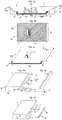
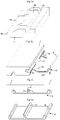
- Figures 1a-1f show known locking systems.
- Figure 1a shows a conventional locking system formed in one piece with the core 5 and configured to lock with angling.
- the floor panel 1, 1' comprises a locking system that has a tongue 10 and a tongue groove 9 that lock vertically and a strip 5 with a locking element 8 that cooperates with a locking groove 14 and locks the edges horizontally.
- Figure 1b and 1c shows a locking system with a separate strip 5 that comprises a locking protrusion 17 connected to a lower lip 12 of the tongue groove 9 that protrudes beyond a vertical plane VP.
- the locking protrusion 17 is located under a horizontal plane HP that intersects the lower part of the tongue 10.
- Such locking system may not provide sufficient locking strength in thin and flexible core material since the lower lip 12 and the outer part of the strip 5 will bend downwards when the edges are exposed to pulling forces and the locking element 8 will slide out from the locking groove 14.
- Figures 1d - 1f show similar locking systems comprising a plastic or metal clip 6 with a locking protrusion 17 connected to an upper part of the lower lip 12 which is located under the tongue 10 and under the cooperating locking surfaces between the tongue and the lower lip 12.
- the clip is connected to an outer part of a lower lip 12 that is positioned beyond the upper lip and beyond the vertical plane VP.
- Figures 2a - 2f show a first embodiment.
- Figure 2a show a cross section of a first and second panel 1, 1' each provided with a surface layer 2 comprising a transparent wear layer 20 which may be coated by a UV cured PU lacquer.
- the first and the second panels 1, 1' are preferably LVT panels.
- a decorative plastic foil 21 is attached to a core 3 and under the transparent layer 20.
- the core 3 that preferably comprises a thermosetting plastic material with a filler may have several core layers, which may have different density and hardness.
- the locking system comprises a tongue 10 at the second edge of the second panel 1', a tongue groove 9 at a first edge of the first panel and a clip 6, that preferably is formed by punching a metal sheet, for example a 0,3 - 0,6 mm aluminium or steel sheet.
- the clip 6 comprises a clip body 7 at a rear side of a first panel 1.
- the clip body comprises an inner part IP that extends inwardly from a first edge of the first panel and an outer part OP that extends outwardly from the first edge of the first panel 1.
- the clip 6 comprises a fixing element 16 located in a fixing groove 15 in the first panel 1 and a locking element 8 located in a locking groove 14 formed in an adjacent second panel 1' that lock the panel edges horizontally and prevents horizontal separation.
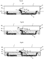
- the clip 6 comprises a locking protrusion 17 formed on the strip body 7 between the locking element 8 and the fixing element 16.
- the locking protrusion 17 projects vertically upwardly from the strip body and is located in a recess 18 formed in the lower lip 12 of the tongue groove 9.
- the recess 18 extends vertically from an upper to a lower part of the lower lip 12.
- the locking protrusion 17 is in this embodiment located such that it is displaced inwardly from the vertical plane VP.
- a part of the locking protrusion 17 extends inwardly into the tongue groove 9 and beyond the outer part of the tongue 10.
- An upper part of the locking protrusion 17 is preferably located above a horizontal plane HP that intersects the lower part of the tongue 10 and the upper part of the lower lip 12.
- the locking protrusion 17 connects the clip 6 vertically to the first panel 1 edge and prevents downward bending of the clip 6 when the edges of the first 1 and the second 1' panels are exposed to separation forces.
- the locking protrusion 17 prevents a displacement of the clip 6 inwardly such that the clip 6 is accurately fixed and positioned in a pre-determined position by the locking protrusion 17 and the fixing element 16.
- the clip 6 may be connected to the core 3 in a horizontal plane HP that is located above the lower lip 12 and to an edge part that is more rigid than an outer part of the lower lip.
- the whole vertical extension of the lower lip 12 and tongue groove 9 may be used to accomplish a strong connection without any essential negative effect on the vertical tongue 10 and tongue groove 9 connection since only a small part of the lower lip 12 will be partially removed when the recess 18 is formed.
- the upper contact surfaces between the tongue 10 and the upper lip 11 are unchanged and may provide an unchanged sealing against moisture penetration into the joint.
- the locking protrusion may be connected to an edge part that comprises sufficient material to allow a strong connection even when the panels are thin for example 3-4 mm and comprise a core 3 of flexible material, such as thermoplastic material mixed with a filler, which is a material composition generally used in LVT floors.
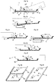
- Figure 2b is a top view of the clip 6.
- Figure 2c shows a clip 6 that has a length direction L along the edge and a width direction W perpendicular to the length.
- a clip with a length of about 3 cm and a width of about 2 cm may provide a locking strength that corresponds to a pulling force of about 200 N. 10 clips/m are sufficient to provide a locking strength on a long edge of about 2000 N.
- Figure 2d shows an edge section of the first panel 1 that comprises a recess 18 formed in the lower lip 12.
- Figure 2e shows the same edge section of the first panel 1 with the surface layer 2 pointing downwards and the recess 18 formed in the lower lip 12.
- Figure 2f shows a clip 6 connected to an edge section of the first panel 1.
- the locking protrusion is located in a recess 18 formed in the lower lip 12.
- FIG. 3a shows that the locking system may be locked with angling.
- the lower lip 12 comprises preferably a sliding surface 24 that guides the tongue 10 into the tongue groove 9 during angling but also during horizontal snapping.
- the sliding surface 24 and a part of the lower lip 12 are located above the outer part OP of the clip body 7.
- Figure 3b shows that the clip 6 may be connected with angling and pressing of the fixing element 16 with a pressing tool P into the fixing groove 15.
- the recess 18 is preferably formed by a vertically rotating tool T that cuts the edge as a saw blade.
- Figures 3c, 3d and 3e show that the clip 6 may be connected by a horizontal displacement and pressing against the fixing element 16 such that a bending of the fixing element 16 takes place.
- Figure 3f shows that the fixing element 16 may be pressed into the core 3 and the fixing groove 15 is formed by the fixing element 16.
- the fixing groove may be pre cut with a knife.
- Glue may also be used to connect the clip 6 to a panel edge. Glue may in some applications replace the fixing grove 15 and the fixing element 16.
- Figure 3g shows that several clips 6a, 6b may be formed by punching a metal sheet and may be inserted after separation from a clip blank comprising several clips.
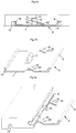
- Figure 3h shows that the clip 6 may have several locking protrusions 17a, 17b.
- Figures 4a - 4c show that the clip 6 may comprise guiding parts 22 having an upwardly extending sliding surface 19 that may facilitate the guiding of the tongue 10 into the tongue groove 9 during angling and/or horizontal snapping.
- the guiding part 22 may also be used to position the clip 6 horizontally against the lower lip 12.
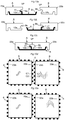
- Figures 5a - 5d show that the recess 18 may be formed in an upper surface of the lower lip 12 and extend along a part of the lower lip.
- Figures 6a - 6c show that the recess 18 may be formed in a lower part of the tongue 10 as shown in figure 6c where the panel 1' is shown with the rear side pointing upwards.
- the locking protrusion 17 is in locked position connected into the tongue groove 9 and located in the recess 18 formed in the lower part of the tongue 10.
- Figures 7a and 7b show that the recess 18,18' may extend from the tongue 10 and to the locking groove 14 in order to accommodate the outer part OP of the clip 6 that extends beyond the upper edge of the panel 1.
- Figures 7c and 7d show that the clip 6 may be an extruded section, for example a plastic or aluminium section.
- Figures 8a and 8b show panels 1, 1' comprising a core 3 with an upper core layer 4a and a lower core layer 4b layer and wherein the locking protrusion 17 protrudes vertically beyond the lower layer 4b.
- Figure 8c shows that the core 3 may comprise a glass fibre layer 4c and the upper part of the locking protrusion may be located above such glass fibre layer 4c.
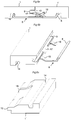
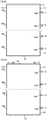
- Figure 9a shows a floor panel 1 comprising several clips 6 and recesses 18a on one of the long edges and several recesses 18b on the opposite long edge.
- the panel comprises a locking system on the short edges that is formed in one piece with the core.
- Figure 9b shows a locking system comprising clips 6 on long and short edges.
- Figures 10a - 10e show that all embodiments of this disclosure may be adapted such that a flooring system may comprise a first A panel and a second B panel comprising clips 6 on at least two opposite edges, a first edge 23a and a second edge 23b.
- the locking system is configured such that a first edge 23a of a first A panel may be locked to a second edge 23b and a first edge 23a of a second panel B.
- Figure 10a shows a cross section C1 - C1 of two adjacent edges 23a and 23b according to figure 10d . Both edges comprise a horizontal groove 9a and 9b and a lower lip 12a, 12b.
- the locking protrusion 17 is preferably located essentially above the lower lip 12a and the lower lip is preferably spaced horizontally from the vertical plane VP.
- Figure 10b show the cross section C2 - C2 in figure 10d and figure 10c shows the cross section C1 - C1 in locked position.
- the clips are offset along the adjacent edges such that they may be inserted between each other.
- Figure 10d shows that a first edge 23a of a first panel A may be locked to a second edge 23b of a second panel B.
- Figure 10e shows that a first edge 23a of the first panel A may also be connected to a first edge 23a of the second panel B.
- the above-described locking system may be used to lock all types of floor panels. Ceramic tiles may be installed with a space between the upper edges. This allows that the outer part of the lower lip 12 may be located at the vertical plane VP or may even protrude horizontally beyond the vertical plane VP and the upper part of the edge.
Claims (11)
- Bauplatten, die mit einem Verriegelungssystem versehen sind, das eine Feder (10) an einer zweiten Kante einer zweiten Platte (1') umfasst, wobei die Feder so ausgeführt ist, dass sie mit einer Federnut (9) an einer ersten Kante einer ersten Platte (1) zum Verriegeln in einer vertikalen Richtung zusammenwirkt, wobei die Federnut (9) eine obere Lippe (11) sowie eine untere Lippe (12) umfasst und das Verriegelungssystem des Weiteren eine oder mehrere Klemmen (6), die an der ersten Kante angebracht ist/sind, sowie eine nach unten offene Verriegelungsnut (14) umfasst, die an der zweiten Kante ausgebildet ist, wobei jede Klemme (6) ein sich nach oben erstreckendes Verriegelungselement (8) umfasst, das so ausgeführt ist, dass es mit der Verriegelungsnut (14) zum Verriegeln der ersten Kante und der zweiten Kante in einer horizontalen Richtung zusammenwirkt, wobei:die Klemme (6) einen Klemmenkörper (7) an einer Rückseite der ersten Platte (1) umfasst, und der Klemmenkörper (7) mit einem inneren Teil (IP), der sich von der ersten Kante nach innen erstreckt, sowie einem äußeren Teil (OP) versehen ist, der sich von der ersten Kante nach außen erstreckt,der innere Teil (IP) ein Fixierelement (16) umfasst, das mit einer nach unten offenen Fixiernut (15) zusammenwirkt, die an der Rückseite der ersten Platte (1) ausgebildet ist, um die Klemme (6) an der ersten Kante in einer horizontalen Richtung zu verriegeln,die Klemme (6) einen Verriegelungsvorsprung (17) umfasst, der von dem Klemmenkörper (7) nach oben vorsteht, wobei der Verriegelungsvorsprung (17) so ausgeführt ist, dass er die Klemme (6) in einer vertikalen Richtung an der ersten Kante verriegelt,die untere Lippe (12) oder die Feder (10) eine Aussparung (18) umfasst, undder Verriegelungsvorsprung (17) in einer verriegelten Position in der Aussparung (18) positioniert ist, dadurch gekennzeichnet, dassdie Klemme (6) Führungsteile (22) mit einer sich nach oben erstreckenden Gleitfläche (19) umfasst, wobei die Gleitfläche (19) so ausgeführt ist, dass sie die Feder (10) beim Abwinkeln und/oder horizontalen Einrasten in die Federnut (9) hinein führt.
- Bauplatten nach Anspruch 1, wobei sich ein Teil des Verriegelungsvorsprungs (17) in der Federnut (9) befindet.
- Bauplatten nach Anspruch 1 oder 2, wobei sich ein Teil des Verriegelungsvorsprungs (17) unterhalb der Feder (10) befindet.
- Bauplatten nach einem der vorangehenden Ansprüche 1 - 3, wobei der Verriegelungsvorsprung (17) einen ersten Teil (17a), der sich von dem Klemmenkörper (7) nach oben erstreckt, und einen zweiten Teil (17b) umfasst, der sich nach innen in die Federnut (9) hinein erstreckt.
- Bauplatten nach einem der vorangehenden Ansprüche 1 - 4, wobei der Verriegelungsvorsprung (17) von einer durch unmittelbar nebeneinander liegende obere Teile der ersten Kante und der zweiten Kante gebildete vertikalen Ebene aus innenliegend positioniert und von ihr beabstandet ist, wobei die vertikale Ebene senkrecht zu einer horizontalen Ebene liegt, die sich parallel zu einer Vorderseite der ersten Platte und der zweiten Platte erstreckt.
- Bauplatten nach einem der Ansprüche 1 - 5, wobei die erste Platte und die zweite Platte einen Kern aus Kunststoffmaterial umfassen.
- Bauplatten nach einem der vorangehenden Ansprüche 1 - 6, wobei die erste Platte und die zweite Platte eine Oberfläche aus thermoplastischem Material umfassen.
- Bauplatten nach einem der vorangehenden Ansprüche 1 - 7, wobei die untere Lippe (12) die Aussparung (18) umfasst und sich die Aussparung (18) vertikal von einem oberen zu einem unteren Teil der unteren Lippe (12) erstreckt und der Verriegelungsvorsprung (17) von der vertikalen Ebene VP aus innenliegend positioniert ist.
- Bauplatten nach einem der vorangehenden Ansprüche 1 - 8, wobei die untere Lippe (12) die Aussparung (18) umfasst und sich die Aussparung (18) entlang eines Teils der unteren Lippe (12) erstreckt.
- Bauplatten nach einem der vorangehenden Ansprüche 1 - 9, wobei der Verriegelungsvorsprung (17) an dem Streifenkörper (7) zwischen dem Verriegelungselement (8) und dem Fixierelement (16) ausgebildet ist.
- Bauplatten nach einem der vorangehenden Ansprüche 1-7 oder 10, wobei die Feder (10) die Aussparung umfasst, und die Aussparung (18, 18') zum Aufnehmen des äußeren Teils (OP) der Klemme (6) sich von der Feder (10) zu der Verriegelungsnut (14) erstreckt.
Applications Claiming Priority (3)
| Application Number | Priority Date | Filing Date | Title |
|---|---|---|---|
| SE1351273 | 2013-10-25 | ||
| EP14856454.5A EP3060728B1 (de) | 2013-10-25 | 2014-10-24 | Mechanisches verschlusssystem für bodenplatten |
| PCT/SE2014/051251 WO2015060780A1 (en) | 2013-10-25 | 2014-10-24 | Mechanical locking system for floor panels |
Related Parent Applications (1)
| Application Number | Title | Priority Date | Filing Date |
|---|---|---|---|
| EP14856454.5A Division EP3060728B1 (de) | 2013-10-25 | 2014-10-24 | Mechanisches verschlusssystem für bodenplatten |
Publications (2)
| Publication Number | Publication Date |
|---|---|
| EP3527743A1 EP3527743A1 (de) | 2019-08-21 |
| EP3527743B1 true EP3527743B1 (de) | 2021-07-07 |
Family
ID=52993249
Family Applications (2)
| Application Number | Title | Priority Date | Filing Date |
|---|---|---|---|
| EP14856454.5A Active EP3060728B1 (de) | 2013-10-25 | 2014-10-24 | Mechanisches verschlusssystem für bodenplatten |
| EP19167121.3A Active EP3527743B1 (de) | 2013-10-25 | 2014-10-24 | Mechanisches arretierungssystem für bodenplatten |
Family Applications Before (1)
| Application Number | Title | Priority Date | Filing Date |
|---|---|---|---|
| EP14856454.5A Active EP3060728B1 (de) | 2013-10-25 | 2014-10-24 | Mechanisches verschlusssystem für bodenplatten |
Country Status (9)
| Country | Link |
|---|---|
| US (3) | US10041258B2 (de) |
| EP (2) | EP3060728B1 (de) |
| KR (1) | KR102314032B1 (de) |
| CN (1) | CN105658883B (de) |
| CA (1) | CA2926336C (de) |
| ES (1) | ES2728351T3 (de) |
| PT (1) | PT3060728T (de) |
| RU (1) | RU2662745C2 (de) |
| WO (1) | WO2015060780A1 (de) |
Families Citing this family (21)
| Publication number | Priority date | Publication date | Assignee | Title |
|---|---|---|---|---|
| US9725912B2 (en) * | 2011-07-11 | 2017-08-08 | Ceraloc Innovation Ab | Mechanical locking system for floor panels |
| US8763340B2 (en) | 2011-08-15 | 2014-07-01 | Valinge Flooring Technology Ab | Mechanical locking system for floor panels |
| JP6397009B2 (ja) | 2013-06-27 | 2018-10-10 | ベーリンゲ、イノベイション、アクチボラグVaelinge Innovation Ab | 機械式係止システムを持つ建材パネル |
| BR112015032687B1 (pt) | 2013-07-09 | 2022-03-15 | Ceraloc Innovation Ab | Conjunto de painéis de piso |
| CA2926336C (en) | 2013-10-25 | 2022-07-05 | Floor Iptech Ab | Mechanical locking system for floor panels |
| EP3189194B1 (de) * | 2014-09-04 | 2019-03-13 | QLX Pty Ltd. | Fussbodenmodul |
| US10138636B2 (en) | 2014-11-27 | 2018-11-27 | Valinge Innovation Ab | Mechanical locking system for floor panels |
| WO2017121851A1 (en) * | 2016-01-15 | 2017-07-20 | Beaulieu International Group Nv | Set of panels, method for manufacturing such set of panels, assembly of the panels and locking profile used in said panels |
| US10557265B2 (en) * | 2016-04-26 | 2020-02-11 | Embassy Ceiling Inc. | Clip for suspended ceiling members |
| BR112020025052A2 (pt) | 2018-06-13 | 2021-03-23 | Ceraloc Innovation Ab | sistema de piso fornecido com um sistema de conexão e um dispositivo de conexão associado |
| NL2021884B1 (en) * | 2018-10-26 | 2020-05-13 | I4F Licensing Nv | Panel, in particular a floor panel or wall panel |
| BE1026806B1 (nl) * | 2018-11-27 | 2020-06-30 | Flooring Ind Ltd Sarl | Paneel en werkwijze voor het vervaardigen van dergelijk paneel |
| PT3670783T (pt) * | 2018-12-21 | 2021-06-30 | SWISS KRONO Tec AG | Grampo de montagem para montagem flutuante de painéis de parede e de teto |
| KR20210110687A (ko) | 2019-01-10 | 2021-09-08 | 뵈린게 이노베이션 에이비이 | 수직으로 잠금해제될 수 있는 패널들의 세트, 이의 방법 및 디바이스 |
| IT201900003627A1 (it) * | 2019-03-13 | 2020-09-13 | Parchettificio Garbelotto S R L | Giunto per pavimenti di listelli |
| DE102019120549A1 (de) * | 2019-07-30 | 2021-02-04 | CliXBond GmbH | Verfahren zum Herstellen eines Verbundprofils, Profilsystem und Verbundbauteil |
| EP3798384A1 (de) * | 2019-09-24 | 2021-03-31 | Välinge Innovation AB | Gebäudeplatte |
| CA3154929A1 (en) * | 2019-09-24 | 2021-04-01 | Valinge Innovation Ab | Building panel |
| EP3798385A1 (de) | 2019-09-24 | 2021-03-31 | Välinge Innovation AB | Gebäudeplatte |
| WO2021087255A1 (en) | 2019-10-31 | 2021-05-06 | Certainteed Llc | Attachment clips for building surface panels and building surface panel system |
| US11773600B2 (en) * | 2021-07-23 | 2023-10-03 | Bath Systems, LLC | Wall paneling system |
Family Cites Families (169)
| Publication number | Priority date | Publication date | Assignee | Title |
|---|---|---|---|---|
| US87853A (en) | 1869-03-16 | Improved mosaic floor | ||
| US274354A (en) | 1883-03-20 | Carthy | ||
| US108068A (en) | 1870-10-04 | Improvement in tiles for roofing | ||
| US213740A (en) | 1879-04-01 | Improvement in wooden roofs | ||
| DE138992C (de) | 1901-07-20 | 1903-02-26 | Gebhard Dietrich | Maschine zur herstellung von holzmosaikplatten aus durch federn miteinander verbundenen holzklötzchen |
| DE142293C (de) | 1902-07-11 | 1903-07-04 | A. Wächter-Leuzinger | Verfahren zur herstellung von bodenplatten aus prismenstücken, die von sich kreuzenden verbindungsstäben zusammengehalten werden |
| US876693A (en) | 1907-01-08 | 1908-01-14 | George H Coldwell | Floor-jack. |
| US1898364A (en) * | 1930-02-24 | 1933-02-21 | George S Gynn | Flooring construction |
| US2110728A (en) | 1933-01-03 | 1938-03-08 | Certain Teed Prod Corp | Construction material and method of making same |
| US2430200A (en) | 1944-11-18 | 1947-11-04 | Nina Mae Wilson | Lock joint |
| US2889016A (en) | 1955-04-13 | 1959-06-02 | Warren Jack | Chassis construction strip and a chassis |
| US3099110A (en) | 1957-09-17 | 1963-07-30 | Dur O Wal National Inc | Control joint |
| US3147522A (en) | 1960-06-01 | 1964-09-08 | Schumm Erich | Flexible tie |
| US3187612A (en) | 1962-12-18 | 1965-06-08 | Robert W Hervey | Method for simultaneously cutting overlapping boards from a single sheet |
| SE515324C2 (sv) | 2000-06-22 | 2001-07-16 | Tarkett Sommer Ab | Golvbräda med kopplingsorgan |
| DE2021503A1 (de) | 1970-05-02 | 1971-11-25 | Freudenberg Carl Fa | Fussbodenplatten und Verfahren zu deren Verbinden |
| DE2159042C3 (de) | 1971-11-29 | 1974-04-18 | Heinrich 6700 Ludwigshafen Hebgen | Dämmplatte, insbesondere aus Kunststoffhartschaum |
| US3939546A (en) | 1974-08-07 | 1976-02-24 | Hernandez Ralph G | Tool for setting jointed flooring panels |
| US4169688A (en) | 1976-03-15 | 1979-10-02 | Sato Toshio | Artificial skating-rink floor |
| US4426820A (en) | 1979-04-24 | 1984-01-24 | Heinz Terbrack | Panel for a composite surface and a method of assembling same |
| US4447172A (en) | 1982-03-18 | 1984-05-08 | Structural Accessories, Inc. | Roadway expansion joint and seal |
| DE3310281A1 (de) | 1983-03-22 | 1984-10-04 | Günter 5902 Netphen Werthebach | Platte fuer wand- und bodenaufbau |
| DK149498C (da) | 1983-04-07 | 1986-12-01 | Inter Ikea As | Beklaedning af braedder til f.eks. gulve eller paneler |
| US4512131A (en) | 1983-10-03 | 1985-04-23 | Laramore Larry W | Plank-type building system |
| DE3343601A1 (de) | 1983-12-02 | 1985-06-13 | Bütec Gesellschaft für bühnentechnische Einrichtungen mbH, 4010 Hilden | Verbindungsanordnung fuer rechteckige platten |
| US4819932A (en) | 1986-02-28 | 1989-04-11 | Trotter Jr Phil | Aerobic exercise floor system |
| US5135597A (en) | 1988-06-23 | 1992-08-04 | Weyerhaeuser Company | Process for remanufacturing wood boards |
| US5272850A (en) | 1991-05-06 | 1993-12-28 | Icon, Incorporated | Panel connector |
| DE4215273C2 (de) | 1992-05-09 | 1996-01-25 | Dietmar Groeger | Belag zur Verkleidung von Boden-, Wand- und/oder Deckenflächen, insbesondere in der Art eines Riemenfußbodens |
| US5295341A (en) | 1992-07-10 | 1994-03-22 | Nikken Seattle, Inc. | Snap-together flooring system |
| JP2550466B2 (ja) | 1992-11-02 | 1996-11-06 | 大建工業株式会社 | 床 材 |
| DE4242530C2 (de) | 1992-12-16 | 1996-09-12 | Walter Friedl | Bauelement für Wände, Decken oder Dächer von Bauwerken |
| SE9301595L (sv) | 1993-05-10 | 1994-10-17 | Tony Pervan | Fog för tunna flytande hårda golv |
| SE509060C2 (sv) | 1996-12-05 | 1998-11-30 | Valinge Aluminium Ab | Metod för tillverkning av byggnadsskiva såsom en golvskiva |
| US5435610A (en) | 1994-03-18 | 1995-07-25 | Charles Taylor | Subfloor panel driving device and method |
| US5485702A (en) | 1994-03-25 | 1996-01-23 | Glenn Sholton | Mortarless glass block assembly |
| SE9500810D0 (sv) | 1995-03-07 | 1995-03-07 | Perstorp Flooring Ab | Golvplatta |
| US5577357A (en) | 1995-07-10 | 1996-11-26 | Civelli; Ken | Half log siding mounting system |
| BR7502683U (pt) | 1995-11-24 | 1996-04-09 | Jacob Abrahams | Disposiçoes construtivas em junçoes de réguas para pisos lambrís ou forros |
| BE1010487A6 (nl) | 1996-06-11 | 1998-10-06 | Unilin Beheer Bv | Vloerbekleding bestaande uit harde vloerpanelen en werkwijze voor het vervaardigen van dergelijke vloerpanelen. |
| US5950389A (en) | 1996-07-02 | 1999-09-14 | Porter; William H. | Splines for joining panels |
| US6203653B1 (en) | 1996-09-18 | 2001-03-20 | Marc A. Seidner | Method of making engineered mouldings |
| US6808777B2 (en) | 1996-11-08 | 2004-10-26 | Ab Golvabia | Flooring |
| SE507737C2 (sv) | 1996-11-08 | 1998-07-06 | Golvabia Ab | Anordning för sammanfogning av golvbeläggningsmaterial |
| SE509059C2 (sv) | 1996-12-05 | 1998-11-30 | Valinge Aluminium Ab | Metod och utrustning för framställning av en byggnadsskiva, såsom en golvskiva |
| US5845548A (en) | 1996-12-06 | 1998-12-08 | Nelson; Jerome S. C. | Flooring tools |
| US6295779B1 (en) | 1997-11-26 | 2001-10-02 | Fred C. Canfield | Composite frame member and method of making the same |
| US5970675A (en) | 1997-12-05 | 1999-10-26 | James D. Wright | Modular panel assembly |
| US7386963B2 (en) | 1998-06-03 | 2008-06-17 | Valinge Innovation Ab | Locking system and flooring board |
| SE512290C2 (sv) | 1998-06-03 | 2000-02-28 | Valinge Aluminium Ab | Låssystem för mekanisk hopfogning av golvskivor samt golvskiva försedd med låssystemet |
| SE512313E (sv) | 1998-06-03 | 2000-02-28 | Valinge Aluminium Ab | Låssystem samt golvskiva |
| SE515789C2 (sv) | 1999-02-10 | 2001-10-08 | Perstorp Flooring Ab | Golvbeläggningsmaterial innefattande golvelement vilka är avsedda att sammanfogas vertikalt |
| SE514645C2 (sv) | 1998-10-06 | 2001-03-26 | Perstorp Flooring Ab | Golvbeläggningsmaterial innefattande skivformiga golvelement avsedda att sammanfogas av separata sammanfogningsprofiler |
| SE513189C2 (sv) | 1998-10-06 | 2000-07-24 | Perstorp Flooring Ab | Vertikalmonterbart golvbeläggningsmaterial innefattande skivformiga golvelement vilka sammanfogas med hjälp av separata sammanfogningsprofiler |
| US6254301B1 (en) | 1999-01-29 | 2001-07-03 | J. Melvon Hatch | Thermoset resin-fiber composites, woodworking dowels and other articles of manufacture made therefrom, and methods |
| IL129834A (en) | 1999-05-06 | 2001-09-13 | Ackerstein Ind Ltd | Ground surface cover system with flexible interlocking joint for erosion control |
| US6358352B1 (en) | 1999-06-25 | 2002-03-19 | Wyoming Sawmills, Inc. | Method for creating higher grade wood products from lower grade lumber |
| SE517009C2 (sv) | 1999-07-05 | 2002-04-02 | Perstorp Flooring Ab | Golvelement med styrdon |
| AT413227B (de) | 1999-07-23 | 2005-12-15 | Kaindl M | Platten- oder leistenförmige bauteile oder anordnung mit derartigen bauteilen und klammer hiefür |
| US6449918B1 (en) | 1999-11-08 | 2002-09-17 | Premark Rwp Holdings, Inc. | Multipanel floor system panel connector with seal |
| US7614197B2 (en) | 1999-11-08 | 2009-11-10 | Premark Rwp Holdings, Inc. | Laminate flooring |
| US6332733B1 (en) | 1999-12-23 | 2001-12-25 | Hamberger Industriewerke Gmbh | Joint |
| AU4743800A (en) | 1999-12-23 | 2001-07-09 | Hamberger Industriewerke Gmbh | Joint |
| DE19963203A1 (de) | 1999-12-27 | 2001-09-20 | Kunnemeyer Hornitex | Verfahren zum Herstellen von plattenförmigen Holzwerkstoffen und Platte aus Holzwerkstoff |
| DE10001076C1 (de) | 2000-01-13 | 2001-10-04 | Huelsta Werke Huels Kg | Paneelelement |
| US20010010139A1 (en) * | 2000-01-27 | 2001-08-02 | Johan De Kerpel | Combined set comprising a locking member and at least two building panels |
| EP1120515A1 (de) | 2000-01-27 | 2001-08-01 | Triax N.V. | Zusammenstellung mit einem Verriegelungselement und mindestens zwei Bauplatten |
| SE518184C2 (sv) | 2000-03-31 | 2002-09-03 | Perstorp Flooring Ab | Golvbeläggningsmaterial innefattande skivformiga golvelement vilka sammanfogas med hjälp av sammankopplingsorgan |
| US6363677B1 (en) | 2000-04-10 | 2002-04-02 | Mannington Mills, Inc. | Surface covering system and methods of installing same |
| FR2810060A1 (fr) | 2000-06-08 | 2001-12-14 | Ykk France | Dispositif d'assemblage de panneaux pour revetement de sol |
| DE10031639C2 (de) | 2000-06-29 | 2002-08-14 | Hw Ind Gmbh & Co Kg | Fussbodenplatte |
| SE0003091D0 (sv) | 2000-07-07 | 2000-09-01 | Ericsson Telefon Ab L M | Communication system |
| US6339908B1 (en) | 2000-07-21 | 2002-01-22 | Fu-Ming Chuang | Wood floor board assembly |
| US6576079B1 (en) | 2000-09-28 | 2003-06-10 | Richard H. Kai | Wooden tiles and method for making the same |
| US6851241B2 (en) | 2001-01-12 | 2005-02-08 | Valinge Aluminium Ab | Floorboards and methods for production and installation thereof |
| IL156528A0 (en) | 2001-01-12 | 2004-01-04 | Valinge Aluminium Ab | Floorboard and locking system |
| SE520084C2 (sv) | 2001-01-31 | 2003-05-20 | Pergo Europ Ab | Förfarande för framställning av sammanfogningsprofiler |
| US6450235B1 (en) | 2001-02-09 | 2002-09-17 | Han-Sen Lee | Efficient, natural slat system |
| DE10201905B4 (de) | 2001-03-26 | 2004-07-08 | Peter Kellner | Fußboden aus einzelnen Elementen |
| AT410815B (de) | 2001-04-05 | 2003-08-25 | Kaindl M | Verbindung von plattenförmigen bauteilen |
| US6550206B2 (en) | 2001-07-12 | 2003-04-22 | Chiu-Ying Lee | Wood floor assembly |
| DE20122553U1 (de) | 2001-08-10 | 2006-03-23 | Akzenta Paneele + Profile Gmbh | Paneel sowie Befestigungssystem für Paneele |
| SE525558C2 (sv) | 2001-09-20 | 2005-03-08 | Vaelinge Innovation Ab | System för bildande av en golvbeläggning, sats av golvskivor samt förfarande för tillverkning av två olika typer av golvskivor |
| FR2831908B1 (fr) | 2001-11-02 | 2004-10-22 | Europ De Laquage Et De Faconna | Dispositif d'assemblage des bords de panneaux, lattes ou lambris |
| US7108031B1 (en) | 2002-01-31 | 2006-09-19 | David Secrest | Method of making patterns in wood and decorative articles of wood made from said method |
| BRPI0308966B8 (pt) | 2002-04-03 | 2016-05-17 | Vaelinge Innovation Ab | tábua de assoalho |
| US7051486B2 (en) | 2002-04-15 | 2006-05-30 | Valinge Aluminium Ab | Mechanical locking system for floating floor |
| CN2546556Y (zh) * | 2002-04-24 | 2003-04-23 | 李文其 | 无缝快速组合地板 |
| KR100465549B1 (ko) | 2002-05-30 | 2005-01-13 | 채완식 | 건축 판재 부착방법 및 부착용 레일식 고정구 |
| EP1441086A1 (de) | 2003-01-14 | 2004-07-28 | Josef Schulte-Führes | Fussbodendiele |
| US20040206036A1 (en) | 2003-02-24 | 2004-10-21 | Valinge Aluminium Ab | Floorboard and method for manufacturing thereof |
| US7677001B2 (en) | 2003-03-06 | 2010-03-16 | Valinge Innovation Ab | Flooring systems and methods for installation |
| SE526691C2 (sv) | 2003-03-18 | 2005-10-25 | Pergo Europ Ab | Panelfog med friktionshöjande medel vid långsidans vridfog |
| DE20304761U1 (de) | 2003-03-24 | 2004-04-08 | Kronotec Ag | Einrichtung zum Verbinden von Bauplatten, insbesondere Bodenpaneele |
| US6862855B1 (en) | 2003-04-16 | 2005-03-08 | Dave G. Milum | Structural assembly for decks, walkways, patios, and docks |
| US7600354B2 (en) | 2003-07-02 | 2009-10-13 | Kaindl Flooring Gmbh | Panels comprising interlocking snap-in profiles |
| KR100566083B1 (ko) | 2003-08-07 | 2006-03-30 | 주식회사 한솔홈데코 | 조립식 바닥재 |
| DE20313661U1 (de) | 2003-09-05 | 2003-11-13 | Kaindl Wals M | Paneel mit geschützter V-Fuge |
| DE10349790A1 (de) | 2003-10-24 | 2005-05-25 | Petec S.A. | Bauelement zur Herstellung von Boden- oder Wandverkleidungen |
| US7171790B2 (en) | 2004-03-22 | 2007-02-06 | Tzu-Chiang Mei | Clamp unit for Do-It-Yourself (DIY) solid wood flooring |
| BE1016216A5 (nl) | 2004-09-24 | 2006-05-02 | Flooring Ind Ltd | Vloerpaneel en vloerbekleding samengesteld uit dergeljke vloerpanelen. |
| SE527570C2 (sv) | 2004-10-05 | 2006-04-11 | Vaelinge Innovation Ab | Anordning och metod för ytbehandling av skivformat ämne samt golvskiva |
| SI1650375T2 (sl) | 2004-10-22 | 2011-04-29 | Vaelinge Innovation Ab | Set talnih panelov |
| US7841144B2 (en) | 2005-03-30 | 2010-11-30 | Valinge Innovation Ab | Mechanical locking system for panels and method of installing same |
| US7454875B2 (en) | 2004-10-22 | 2008-11-25 | Valinge Aluminium Ab | Mechanical locking system for floor panels |
| CN2761740Y (zh) * | 2005-01-11 | 2006-03-01 | 圣象实业(深圳)有限公司 | 一种具曲面的卡扣型地板 |
| EP1715248A1 (de) | 2005-04-19 | 2006-10-25 | Siemens Aktiengesellschaft | Halteelement und Hitzeschildelement für einen Hitzeschild sowie mit einem Hitzeschild versehene Brennkammer |
| US8061104B2 (en) | 2005-05-20 | 2011-11-22 | Valinge Innovation Ab | Mechanical locking system for floor panels |
| SE529076C2 (sv) | 2005-07-11 | 2007-04-24 | Pergo Europ Ab | En fog till paneler |
| DE102005038975B3 (de) | 2005-08-16 | 2006-12-14 | Johannes Schulte | Verfahren zur Herstellung von Paneelen |
| CA2618496C (en) | 2005-08-16 | 2010-02-09 | Johannes Schulte | Method for production of panels |
| US20070151189A1 (en) | 2006-01-03 | 2007-07-05 | Feng-Ling Yang | Securing device for combining floor plates |
| DE102006020135A1 (de) | 2006-05-02 | 2007-11-15 | Deutsche Amphibolin-Werke Von Robert Murjahn Stiftung & Co Kg | Fußbodenbelag aus Fußbodenpaneelen mit einem mineralischen Kern mit mechanischen Verriegelungsmitteln und Natur- oder künstlichem Steinmaterial oder Glas als Deckschicht |
| KR100762943B1 (ko) | 2006-05-19 | 2007-10-02 | 주식회사 한솔홈데코 | 결합구를 이용한 조립식 바닥재 및 이의 조립 방법 |
| BE1017157A3 (nl) | 2006-06-02 | 2008-03-04 | Flooring Ind Ltd | Vloerbekleding, vloerelement en werkwijze voor het vervaardigen van vloerelementen. |
| SE530048C2 (sv) | 2006-06-09 | 2008-02-19 | Burseryd Innovation Ab | Fästelement samt metod att sammanfoga dynamiska kroppar medelst fästelementet |
| SE533410C2 (sv) | 2006-07-11 | 2010-09-14 | Vaelinge Innovation Ab | Golvpaneler med mekaniska låssystem med en flexibel och förskjutbar tunga samt tunga därför |
| US7654055B2 (en) | 2006-08-08 | 2010-02-02 | Ricker Michael B | Glueless panel locking system |
| DE102006037614B3 (de) | 2006-08-10 | 2007-12-20 | Guido Schulte | Fußbodenbelag und Verlegeverfahren |
| US7257926B1 (en) | 2006-08-24 | 2007-08-21 | Kirby Mark E | Tile spacer and leveler |
| US8689512B2 (en) | 2006-11-15 | 2014-04-08 | Valinge Innovation Ab | Mechanical locking of floor panels with vertical folding |
| SE531111C2 (sv) | 2006-12-08 | 2008-12-23 | Vaelinge Innovation Ab | Mekanisk låsning av golvpaneler |
| US7984600B2 (en) | 2007-02-02 | 2011-07-26 | Mohawk Carpet Corporation | Groutless tile system and method for making the same |
| DE102007015048B4 (de) | 2007-03-26 | 2009-03-05 | Kronotec Ag | Paneel, insbesondere Bodenpaneel |
| US7726088B2 (en) | 2007-07-20 | 2010-06-01 | Moritz Andre Muehlebach | Flooring system |
| DE102007042250B4 (de) | 2007-09-06 | 2010-04-22 | Flooring Technologies Ltd. | Einrichtung zur Verbindung und Verriegelung zweier Bauplatten, insbesondere Fussbodenpaneele |
| US8353140B2 (en) | 2007-11-07 | 2013-01-15 | Valinge Innovation Ab | Mechanical locking of floor panels with vertical snap folding |
| US7805903B2 (en) | 2007-12-13 | 2010-10-05 | Liu David C | Locking mechanism for flooring boards |
| DE102008003550B4 (de) | 2008-01-09 | 2009-10-22 | Flooring Technologies Ltd. | Einrichtung und Verfahren zum Verriegeln zweier Bodenpaneele |
| US8505257B2 (en) | 2008-01-31 | 2013-08-13 | Valinge Innovation Ab | Mechanical locking of floor panels |
| MY152779A (en) | 2008-01-31 | 2014-11-28 | Valinge Innovation Ab | Mechanical locking of floor panels, methods to install and uninstall panels, a method and an equipment to produce the locking system, a method to connect a displaceable tongue to a panel and a tongue blank |
| CN102066674B (zh) | 2008-05-15 | 2015-06-03 | 瓦林格创新股份有限公司 | 具有通过磁场启动的机械锁定系统的地板镶板及安装镶板的方法 |
| US20100132295A1 (en) * | 2008-11-26 | 2010-06-03 | Harold Bootier | Siding containing composite building material and siding clip |
| US7998549B2 (en) | 2009-01-08 | 2011-08-16 | Thermwood Corporation | Structure and method of assembly thereof |
| BE1018627A5 (nl) | 2009-01-16 | 2011-05-03 | Flooring Ind Ltd Sarl | Vloerpaneel. |
| WO2010087752A1 (en) | 2009-01-30 | 2010-08-05 | Välinge Innovation Belgium BVBA | Mechanical lockings of floor panels and a tongue blank |
| DE102009035275A1 (de) | 2009-06-08 | 2010-12-09 | Fritz Egger Gmbh & Co. | Paneel eines Fußbodensystems |
| BE1018802A3 (nl) | 2009-06-29 | 2011-09-06 | Flooring Ind Ltd Sarl | Paneel, meer speciaal vloerpaneel. |
| TWM373948U (en) | 2009-07-22 | 2010-02-11 | Feng-Ling Yang | Assembly floor |
| ES1070838Y (es) | 2009-08-10 | 2010-02-01 | Azteca Sergrup S L | Pavimento modular |
| CN201588375U (zh) | 2009-09-29 | 2010-09-22 | 钟玉东 | 镶嵌式组合实木地板 |
| DE102009048050B3 (de) | 2009-10-02 | 2011-01-20 | Guido Schulte | Belag aus mechanischen miteinander verbindbaren Elementen |
| US8539727B2 (en) | 2009-11-19 | 2013-09-24 | Sun Wah Lui | Mechanically-held tile |
| US8429870B2 (en) | 2009-12-04 | 2013-04-30 | Mannington Mills, Inc. | Connecting system for surface coverings |
| BR112012018285B1 (pt) | 2010-02-04 | 2020-02-18 | Välinge Innovation AB | Conjunto de painéis de piso |
| US8234830B2 (en) | 2010-02-04 | 2012-08-07 | Välinge Innovations AB | Mechanical locking system for floor panels |
| US20110197535A1 (en) | 2010-02-13 | 2011-08-18 | Geoffrey Alan Baker | Laying and mechanically joining building panels or construction elements |
| DE102010012572B3 (de) | 2010-03-23 | 2011-07-14 | Fritz Egger Gmbh & Co. Og | System von wenigstens zwei Paneelen |
| DE212010000195U1 (de) | 2010-04-15 | 2012-08-06 | Spanolux N.V. Div. Balterio | Bodenplattenanordnung |
| EP2397623B1 (de) | 2010-06-17 | 2018-01-31 | Unilin, BVBA | Paneelverbindungsanordnung |
| WO2012045343A1 (de) | 2010-10-06 | 2012-04-12 | Knauf Gips Kg | FUßBODENBELAG SOWIE FUßBODENPANEEL |
| CN102518283A (zh) * | 2010-12-24 | 2012-06-27 | 张家铭 | 一种锁扣拼接地板的地板块及锁扣夹条 |
| GB2483525B (en) | 2011-02-03 | 2013-05-01 | Oliver James Furniture Ltd | A panel connection system |
| EP2492416A1 (de) | 2011-02-28 | 2012-08-29 | Silicalia S.L. | System zur Fußbodenabdeckung |
| UA114715C2 (uk) | 2011-07-05 | 2017-07-25 | Сералок Інновейшн Аб | Механічна фіксація панелей настилу підлоги до язичка з нанесеним шаром клею |
| US9725912B2 (en) | 2011-07-11 | 2017-08-08 | Ceraloc Innovation Ab | Mechanical locking system for floor panels |
| US8650826B2 (en) | 2011-07-19 | 2014-02-18 | Valinge Flooring Technology Ab | Mechanical locking system for floor panels |
| US8763340B2 (en) | 2011-08-15 | 2014-07-01 | Valinge Flooring Technology Ab | Mechanical locking system for floor panels |
| US8857126B2 (en) | 2011-08-15 | 2014-10-14 | Valinge Flooring Technology Ab | Mechanical locking system for floor panels |
| US8769905B2 (en) | 2011-08-15 | 2014-07-08 | Valinge Flooring Technology Ab | Mechanical locking system for floor panels |
| WO2013025165A1 (en) * | 2011-08-15 | 2013-02-21 | Välinge Flooring Technology AB | Mechanical locking system for floor panels |
| RU2672903C2 (ru) * | 2011-08-29 | 2018-11-20 | Сералок Инновейшн Аб | Механическая блокировочная система для панелей пола |
| ITRN20110067A1 (it) | 2011-09-19 | 2011-12-19 | Ceramica Faetano S P A | Pavimento ceramico a piastrelle. |
| CN102383575A (zh) * | 2011-11-23 | 2012-03-21 | 李渊 | 饰面板铺装结构 |
| DE102011120702A1 (de) * | 2011-12-09 | 2013-06-13 | SÜDDEKOR GmbH | Transferverfahren zur Herstellung thermoplastischer Beschichtungen von Fußbodenfliesen |
| BR112015032687B1 (pt) | 2013-07-09 | 2022-03-15 | Ceraloc Innovation Ab | Conjunto de painéis de piso |
| CA2926336C (en) | 2013-10-25 | 2022-07-05 | Floor Iptech Ab | Mechanical locking system for floor panels |
| US9441379B2 (en) | 2014-08-27 | 2016-09-13 | Evan J. Stover | Flooring system having assembly clip and related method |
| BR112020025052A2 (pt) | 2018-06-13 | 2021-03-23 | Ceraloc Innovation Ab | sistema de piso fornecido com um sistema de conexão e um dispositivo de conexão associado |
-
2014
- 2014-10-24 CA CA2926336A patent/CA2926336C/en active Active
- 2014-10-24 PT PT14856454T patent/PT3060728T/pt unknown
- 2014-10-24 RU RU2016119208A patent/RU2662745C2/ru active
- 2014-10-24 CN CN201480057320.9A patent/CN105658883B/zh active Active
- 2014-10-24 EP EP14856454.5A patent/EP3060728B1/de active Active
- 2014-10-24 US US15/028,831 patent/US10041258B2/en active Active
- 2014-10-24 KR KR1020167013176A patent/KR102314032B1/ko active IP Right Grant
- 2014-10-24 WO PCT/SE2014/051251 patent/WO2015060780A1/en active Application Filing
- 2014-10-24 ES ES14856454T patent/ES2728351T3/es active Active
- 2014-10-24 EP EP19167121.3A patent/EP3527743B1/de active Active
-
2018
- 2018-02-21 US US15/901,614 patent/US10626620B2/en active Active
-
2020
- 2020-03-18 US US16/822,130 patent/US11391050B2/en active Active
Non-Patent Citations (1)
| Title |
|---|
| None * |
Also Published As
| Publication number | Publication date |
|---|---|
| US20180179764A1 (en) | 2018-06-28 |
| EP3060728A1 (de) | 2016-08-31 |
| EP3527743A1 (de) | 2019-08-21 |
| US20200217083A1 (en) | 2020-07-09 |
| CN105658883A (zh) | 2016-06-08 |
| KR20160075602A (ko) | 2016-06-29 |
| PT3060728T (pt) | 2019-06-14 |
| CN105658883B (zh) | 2019-07-26 |
| KR102314032B1 (ko) | 2021-10-15 |
| CA2926336A1 (en) | 2015-04-30 |
| RU2662745C2 (ru) | 2018-07-30 |
| US10041258B2 (en) | 2018-08-07 |
| US10626620B2 (en) | 2020-04-21 |
| RU2016119208A (ru) | 2017-11-28 |
| WO2015060780A1 (en) | 2015-04-30 |
| US20160237695A1 (en) | 2016-08-18 |
| US11391050B2 (en) | 2022-07-19 |
| EP3060728A4 (de) | 2017-06-21 |
| RU2016119208A3 (de) | 2018-05-30 |
| ES2728351T3 (es) | 2019-10-23 |
| BR112016008281A2 (de) | 2017-08-01 |
| BR112016008281A8 (pt) | 2018-04-03 |
| EP3060728B1 (de) | 2019-04-10 |
| CA2926336C (en) | 2022-07-05 |
Similar Documents
| Publication | Publication Date | Title |
|---|---|---|
| EP3527743B1 (de) | Mechanisches arretierungssystem für bodenplatten | |
| US10697187B2 (en) | Mechanical locking system for floor panels | |
| EP2402527B1 (de) | Fussbodensystem umfassend mehrere Bodenplatten | |
| JP4472355B2 (ja) | フロアボード用機械式係止システム | |
| EP3460142B1 (de) | Mechanisches arretierungssystem für bodenplatten | |
| BR112016008281B1 (pt) | Sistema de travamento mecânico para painéis de piso |
Legal Events
| Date | Code | Title | Description |
|---|---|---|---|
| PUAI | Public reference made under article 153(3) epc to a published international application that has entered the european phase |
Free format text: ORIGINAL CODE: 0009012 |
|
| STAA | Information on the status of an ep patent application or granted ep patent |
Free format text: STATUS: REQUEST FOR EXAMINATION WAS MADE |
|
| 17P | Request for examination filed |
Effective date: 20190403 |
|
| AC | Divisional application: reference to earlier application |
Ref document number: 3060728 Country of ref document: EP Kind code of ref document: P |
|
| AK | Designated contracting states |
Kind code of ref document: A1 Designated state(s): AL AT BE BG CH CY CZ DE DK EE ES FI FR GB GR HR HU IE IS IT LI LT LU LV MC MK MT NL NO PL PT RO RS SE SI SK SM TR |
|
| RIC1 | Information provided on ipc code assigned before grant |
Ipc: E04F 15/02 20060101AFI20200520BHEP Ipc: E04F 15/10 20060101ALI20200520BHEP |
|
| STAA | Information on the status of an ep patent application or granted ep patent |
Free format text: STATUS: EXAMINATION IS IN PROGRESS |
|
| RIN1 | Information on inventor provided before grant (corrected) |
Inventor name: PERVAN, DARKO |
|
| 17Q | First examination report despatched |
Effective date: 20200706 |
|
| STAA | Information on the status of an ep patent application or granted ep patent |
Free format text: STATUS: EXAMINATION IS IN PROGRESS |
|
| GRAP | Despatch of communication of intention to grant a patent |
Free format text: ORIGINAL CODE: EPIDOSNIGR1 |
|
| STAA | Information on the status of an ep patent application or granted ep patent |
Free format text: STATUS: GRANT OF PATENT IS INTENDED |
|
| INTG | Intention to grant announced |
Effective date: 20210203 |
|
| GRAS | Grant fee paid |
Free format text: ORIGINAL CODE: EPIDOSNIGR3 |
|
| GRAA | (expected) grant |
Free format text: ORIGINAL CODE: 0009210 |
|
| STAA | Information on the status of an ep patent application or granted ep patent |
Free format text: STATUS: THE PATENT HAS BEEN GRANTED |
|
| AC | Divisional application: reference to earlier application |
Ref document number: 3060728 Country of ref document: EP Kind code of ref document: P |
|
| AK | Designated contracting states |
Kind code of ref document: B1 Designated state(s): AL AT BE BG CH CY CZ DE DK EE ES FI FR GB GR HR HU IE IS IT LI LT LU LV MC MK MT NL NO PL PT RO RS SE SI SK SM TR |
|
| RAP3 | Party data changed (applicant data changed or rights of an application transferred) |
Owner name: CERALOC INNOVATION AB |
|
| REG | Reference to a national code |
Ref country code: GB Ref legal event code: FG4D |
|
| REG | Reference to a national code |
Ref country code: AT Ref legal event code: REF Ref document number: 1408737 Country of ref document: AT Kind code of ref document: T Effective date: 20210715 |
|
| REG | Reference to a national code |
Ref country code: DE Ref legal event code: R096 Ref document number: 602014078703 Country of ref document: DE |
|
| REG | Reference to a national code |
Ref country code: IE Ref legal event code: FG4D |
|
| REG | Reference to a national code |
Ref country code: LT Ref legal event code: MG9D |
|
| REG | Reference to a national code |
Ref country code: NL Ref legal event code: MP Effective date: 20210707 |
|
| REG | Reference to a national code |
Ref country code: AT Ref legal event code: MK05 Ref document number: 1408737 Country of ref document: AT Kind code of ref document: T Effective date: 20210707 |
|
| PG25 | Lapsed in a contracting state [announced via postgrant information from national office to epo] |
Ref country code: SE Free format text: LAPSE BECAUSE OF FAILURE TO SUBMIT A TRANSLATION OF THE DESCRIPTION OR TO PAY THE FEE WITHIN THE PRESCRIBED TIME-LIMIT Effective date: 20210707 Ref country code: RS Free format text: LAPSE BECAUSE OF FAILURE TO SUBMIT A TRANSLATION OF THE DESCRIPTION OR TO PAY THE FEE WITHIN THE PRESCRIBED TIME-LIMIT Effective date: 20210707 Ref country code: ES Free format text: LAPSE BECAUSE OF FAILURE TO SUBMIT A TRANSLATION OF THE DESCRIPTION OR TO PAY THE FEE WITHIN THE PRESCRIBED TIME-LIMIT Effective date: 20210707 Ref country code: FI Free format text: LAPSE BECAUSE OF FAILURE TO SUBMIT A TRANSLATION OF THE DESCRIPTION OR TO PAY THE FEE WITHIN THE PRESCRIBED TIME-LIMIT Effective date: 20210707 Ref country code: LT Free format text: LAPSE BECAUSE OF FAILURE TO SUBMIT A TRANSLATION OF THE DESCRIPTION OR TO PAY THE FEE WITHIN THE PRESCRIBED TIME-LIMIT Effective date: 20210707 Ref country code: AT Free format text: LAPSE BECAUSE OF FAILURE TO SUBMIT A TRANSLATION OF THE DESCRIPTION OR TO PAY THE FEE WITHIN THE PRESCRIBED TIME-LIMIT Effective date: 20210707 Ref country code: BG Free format text: LAPSE BECAUSE OF FAILURE TO SUBMIT A TRANSLATION OF THE DESCRIPTION OR TO PAY THE FEE WITHIN THE PRESCRIBED TIME-LIMIT Effective date: 20211007 Ref country code: NL Free format text: LAPSE BECAUSE OF FAILURE TO SUBMIT A TRANSLATION OF THE DESCRIPTION OR TO PAY THE FEE WITHIN THE PRESCRIBED TIME-LIMIT Effective date: 20210707 Ref country code: PT Free format text: LAPSE BECAUSE OF FAILURE TO SUBMIT A TRANSLATION OF THE DESCRIPTION OR TO PAY THE FEE WITHIN THE PRESCRIBED TIME-LIMIT Effective date: 20211108 Ref country code: NO Free format text: LAPSE BECAUSE OF FAILURE TO SUBMIT A TRANSLATION OF THE DESCRIPTION OR TO PAY THE FEE WITHIN THE PRESCRIBED TIME-LIMIT Effective date: 20211007 Ref country code: HR Free format text: LAPSE BECAUSE OF FAILURE TO SUBMIT A TRANSLATION OF THE DESCRIPTION OR TO PAY THE FEE WITHIN THE PRESCRIBED TIME-LIMIT Effective date: 20210707 |
|
| PG25 | Lapsed in a contracting state [announced via postgrant information from national office to epo] |
Ref country code: PL Free format text: LAPSE BECAUSE OF FAILURE TO SUBMIT A TRANSLATION OF THE DESCRIPTION OR TO PAY THE FEE WITHIN THE PRESCRIBED TIME-LIMIT Effective date: 20210707 Ref country code: LV Free format text: LAPSE BECAUSE OF FAILURE TO SUBMIT A TRANSLATION OF THE DESCRIPTION OR TO PAY THE FEE WITHIN THE PRESCRIBED TIME-LIMIT Effective date: 20210707 Ref country code: GR Free format text: LAPSE BECAUSE OF FAILURE TO SUBMIT A TRANSLATION OF THE DESCRIPTION OR TO PAY THE FEE WITHIN THE PRESCRIBED TIME-LIMIT Effective date: 20211008 |
|
| REG | Reference to a national code |
Ref country code: DE Ref legal event code: R097 Ref document number: 602014078703 Country of ref document: DE |
|
| PG25 | Lapsed in a contracting state [announced via postgrant information from national office to epo] |
Ref country code: DK Free format text: LAPSE BECAUSE OF FAILURE TO SUBMIT A TRANSLATION OF THE DESCRIPTION OR TO PAY THE FEE WITHIN THE PRESCRIBED TIME-LIMIT Effective date: 20210707 |
|
| PLBE | No opposition filed within time limit |
Free format text: ORIGINAL CODE: 0009261 |
|
| STAA | Information on the status of an ep patent application or granted ep patent |
Free format text: STATUS: NO OPPOSITION FILED WITHIN TIME LIMIT |
|
| REG | Reference to a national code |
Ref country code: CH Ref legal event code: PL |
|
| PG25 | Lapsed in a contracting state [announced via postgrant information from national office to epo] |
Ref country code: SM Free format text: LAPSE BECAUSE OF FAILURE TO SUBMIT A TRANSLATION OF THE DESCRIPTION OR TO PAY THE FEE WITHIN THE PRESCRIBED TIME-LIMIT Effective date: 20210707 Ref country code: SK Free format text: LAPSE BECAUSE OF FAILURE TO SUBMIT A TRANSLATION OF THE DESCRIPTION OR TO PAY THE FEE WITHIN THE PRESCRIBED TIME-LIMIT Effective date: 20210707 Ref country code: RO Free format text: LAPSE BECAUSE OF FAILURE TO SUBMIT A TRANSLATION OF THE DESCRIPTION OR TO PAY THE FEE WITHIN THE PRESCRIBED TIME-LIMIT Effective date: 20210707 Ref country code: EE Free format text: LAPSE BECAUSE OF FAILURE TO SUBMIT A TRANSLATION OF THE DESCRIPTION OR TO PAY THE FEE WITHIN THE PRESCRIBED TIME-LIMIT Effective date: 20210707 Ref country code: CZ Free format text: LAPSE BECAUSE OF FAILURE TO SUBMIT A TRANSLATION OF THE DESCRIPTION OR TO PAY THE FEE WITHIN THE PRESCRIBED TIME-LIMIT Effective date: 20210707 Ref country code: AL Free format text: LAPSE BECAUSE OF FAILURE TO SUBMIT A TRANSLATION OF THE DESCRIPTION OR TO PAY THE FEE WITHIN THE PRESCRIBED TIME-LIMIT Effective date: 20210707 |
|
| 26N | No opposition filed |
Effective date: 20220408 |
|
| REG | Reference to a national code |
Ref country code: BE Ref legal event code: MM Effective date: 20211031 |
|
| GBPC | Gb: european patent ceased through non-payment of renewal fee |
Effective date: 20211024 |
|
| PG25 | Lapsed in a contracting state [announced via postgrant information from national office to epo] |
Ref country code: MC Free format text: LAPSE BECAUSE OF FAILURE TO SUBMIT A TRANSLATION OF THE DESCRIPTION OR TO PAY THE FEE WITHIN THE PRESCRIBED TIME-LIMIT Effective date: 20210707 |
|
| PG25 | Lapsed in a contracting state [announced via postgrant information from national office to epo] |
Ref country code: LU Free format text: LAPSE BECAUSE OF NON-PAYMENT OF DUE FEES Effective date: 20211024 Ref country code: IT Free format text: LAPSE BECAUSE OF FAILURE TO SUBMIT A TRANSLATION OF THE DESCRIPTION OR TO PAY THE FEE WITHIN THE PRESCRIBED TIME-LIMIT Effective date: 20210707 Ref country code: GB Free format text: LAPSE BECAUSE OF NON-PAYMENT OF DUE FEES Effective date: 20211024 Ref country code: BE Free format text: LAPSE BECAUSE OF NON-PAYMENT OF DUE FEES Effective date: 20211031 |
|
| PG25 | Lapsed in a contracting state [announced via postgrant information from national office to epo] |
Ref country code: LI Free format text: LAPSE BECAUSE OF NON-PAYMENT OF DUE FEES Effective date: 20211031 Ref country code: CH Free format text: LAPSE BECAUSE OF NON-PAYMENT OF DUE FEES Effective date: 20211031 |
|
| PG25 | Lapsed in a contracting state [announced via postgrant information from national office to epo] |
Ref country code: IE Free format text: LAPSE BECAUSE OF NON-PAYMENT OF DUE FEES Effective date: 20211024 |
|
| P01 | Opt-out of the competence of the unified patent court (upc) registered |
Effective date: 20230522 |
|
| PG25 | Lapsed in a contracting state [announced via postgrant information from national office to epo] |
Ref country code: CY Free format text: LAPSE BECAUSE OF FAILURE TO SUBMIT A TRANSLATION OF THE DESCRIPTION OR TO PAY THE FEE WITHIN THE PRESCRIBED TIME-LIMIT Effective date: 20210707 |
|
| PG25 | Lapsed in a contracting state [announced via postgrant information from national office to epo] |
Ref country code: HU Free format text: LAPSE BECAUSE OF FAILURE TO SUBMIT A TRANSLATION OF THE DESCRIPTION OR TO PAY THE FEE WITHIN THE PRESCRIBED TIME-LIMIT; INVALID AB INITIO Effective date: 20141024 |
|
| PGFP | Annual fee paid to national office [announced via postgrant information from national office to epo] |
Ref country code: FR Payment date: 20230920 Year of fee payment: 10 |
|
| PGFP | Annual fee paid to national office [announced via postgrant information from national office to epo] |
Ref country code: DE Payment date: 20230920 Year of fee payment: 10 |