US5272850A - Panel connector - Google Patents
Panel connector Download PDFInfo
- Publication number
- US5272850A US5272850A US07/695,972 US69597291A US5272850A US 5272850 A US5272850 A US 5272850A US 69597291 A US69597291 A US 69597291A US 5272850 A US5272850 A US 5272850A
- Authority
- US
- United States
- Prior art keywords
- members
- connector
- panel
- panels
- assembled
- Prior art date
- Legal status (The legal status is an assumption and is not a legal conclusion. Google has not performed a legal analysis and makes no representation as to the accuracy of the status listed.)
- Expired - Lifetime
Links
- 239000002131 composite material Substances 0.000 claims description 26
- 230000000295 complement effect Effects 0.000 claims description 17
- 230000013011 mating Effects 0.000 claims description 12
- 230000006835 compression Effects 0.000 claims description 2
- 238000007906 compression Methods 0.000 claims description 2
- 238000005192 partition Methods 0.000 description 8
- 210000002105 tongue Anatomy 0.000 description 4
- 239000000463 material Substances 0.000 description 2
- 238000000926 separation method Methods 0.000 description 2
- 239000004677 Nylon Substances 0.000 description 1
- 239000004952 Polyamide Substances 0.000 description 1
- 239000000853 adhesive Substances 0.000 description 1
- 230000001070 adhesive effect Effects 0.000 description 1
- XAGFODPZIPBFFR-UHFFFAOYSA-N aluminium Chemical compound [Al] XAGFODPZIPBFFR-UHFFFAOYSA-N 0.000 description 1
- 229910052782 aluminium Inorganic materials 0.000 description 1
- 238000005304 joining Methods 0.000 description 1
- 238000004519 manufacturing process Methods 0.000 description 1
- 238000000034 method Methods 0.000 description 1
- 229920001778 nylon Polymers 0.000 description 1
- 239000004033 plastic Substances 0.000 description 1
- 229920002647 polyamide Polymers 0.000 description 1
- 238000009877 rendering Methods 0.000 description 1
- 238000004513 sizing Methods 0.000 description 1
- 239000007787 solid Substances 0.000 description 1
Images


Classifications
-
- E—FIXED CONSTRUCTIONS
- E04—BUILDING
- E04B—GENERAL BUILDING CONSTRUCTIONS; WALLS, e.g. PARTITIONS; ROOFS; FLOORS; CEILINGS; INSULATION OR OTHER PROTECTION OF BUILDINGS
- E04B2/00—Walls, e.g. partitions, for buildings; Wall construction with regard to insulation; Connections specially adapted to walls
- E04B2/74—Removable non-load-bearing partitions; Partitions with a free upper edge
- E04B2/7407—Removable non-load-bearing partitions; Partitions with a free upper edge assembled using frames with infill panels or coverings only; made-up of panels and a support structure incorporating posts
- E04B2/7409—Removable non-load-bearing partitions; Partitions with a free upper edge assembled using frames with infill panels or coverings only; made-up of panels and a support structure incorporating posts special measures for sound or thermal insulation, including fire protection
-
- E—FIXED CONSTRUCTIONS
- E04—BUILDING
- E04B—GENERAL BUILDING CONSTRUCTIONS; WALLS, e.g. PARTITIONS; ROOFS; FLOORS; CEILINGS; INSULATION OR OTHER PROTECTION OF BUILDINGS
- E04B1/00—Constructions in general; Structures which are not restricted either to walls, e.g. partitions, or floors or ceilings or roofs
- E04B1/38—Connections for building structures in general
- E04B1/61—Connections for building structures in general of slab-shaped building elements with each other
- E04B1/6108—Connections for building structures in general of slab-shaped building elements with each other the frontal surfaces of the slabs connected together
- E04B1/612—Connections for building structures in general of slab-shaped building elements with each other the frontal surfaces of the slabs connected together by means between frontal surfaces
- E04B1/6145—Connections for building structures in general of slab-shaped building elements with each other the frontal surfaces of the slabs connected together by means between frontal surfaces with recesses in both frontal surfaces co-operating with an additional connecting element
- E04B1/6158—Connections for building structures in general of slab-shaped building elements with each other the frontal surfaces of the slabs connected together by means between frontal surfaces with recesses in both frontal surfaces co-operating with an additional connecting element the connection made by formlocking
-
- F—MECHANICAL ENGINEERING; LIGHTING; HEATING; WEAPONS; BLASTING
- F16—ENGINEERING ELEMENTS AND UNITS; GENERAL MEASURES FOR PRODUCING AND MAINTAINING EFFECTIVE FUNCTIONING OF MACHINES OR INSTALLATIONS; THERMAL INSULATION IN GENERAL
- F16B—DEVICES FOR FASTENING OR SECURING CONSTRUCTIONAL ELEMENTS OR MACHINE PARTS TOGETHER, e.g. NAILS, BOLTS, CIRCLIPS, CLAMPS, CLIPS OR WEDGES; JOINTS OR JOINTING
- F16B5/00—Joining sheets or plates, e.g. panels, to one another or to strips or bars parallel to them
- F16B5/0004—Joining sheets, plates or panels in abutting relationship
- F16B5/0032—Joining sheets, plates or panels in abutting relationship by moving the sheets, plates, or panels or the interlocking key parallel to the abutting edge
- F16B5/0044—Joining sheets, plates or panels in abutting relationship by moving the sheets, plates, or panels or the interlocking key parallel to the abutting edge and using interlocking keys of circular, square, rectangular or like shape
Definitions
- the present invention pertains to display hardware, partitions, movable walls, and structural panels, subject to repeated assembly and disassembly, and more particularly pertains to a panel or partition connector.
- a panel connector comprising first and second members and a lock.
- the first and second members define an axis.
- the first and second members are slideable in relation to each other along the axis.
- the members also are slideable in relation to each other transverse to the axis.
- the lock has engaged parts connected to the first and second members, respectively.
- the lock limits movement of the members transverse to the axis.
- the lock is disengaged by movement of the members axially relative to the lock.
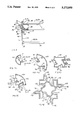
- FIG. 1 is a perspective view of an embodiment of the panel connector of the invention and a pair of panel members in joined condition. The location of lock parts is indicated by dashed lines.
- FIG. 2 is a partial cross-sectional view of the panels and panel connector of FIG. 1, taken substantially along section line 2--2.
- FIG. 3 is a partial side plan view of the panels and panel connector of FIG. 1.
- a first member is shown in a disassembled configuration in solid lines and in partially assembled and assembled configurations in dashed lines.
- a second member, in all configurations, is shown in solid lines.
- FIG. 4 is a partial cross-sectional view of an alternative embodiment of the panel connector of the invention similar to FIG. 2.
- FIG. 5 is a partial cross-sectional view of another alternative embodiment of the panel connector of the invention similar to FIG. 2.
- FIG. 6 is a partial cross-sectional view of yet another alternative embodiment of the panel connector of the invention similar to FIG. 2.
- FIG. 7 is a partial cross-sectional view of yet another alternative embodiment of the panel connector of the invention similar to FIG. 2.
- FIG. 8 is a partial cross-sectional view of yet another alternative embodiment of the panel connector of the invention similar to FIG. 7.
- FIGS. 9A through E are cross-sectional views of end caps and connectors of the embodiments shown in FIGS. 7 and 8.
- FIG. 10 is a partial perspective view of a lock mechanism for use with the panel connector of the invention alternative to that shown in FIG. 3.
- the panel connector 10 of the invention provides an improved partition movable wall or structural panel, and more particularly, improved hardware for such structures.
- the improved panel connector of the invention provides a connector which allows large and heavy structural panels, movable walls and/or structural partitions to be assembled and disassembled relatively easily and yet result in a strong and stable structure.
- the several embodiments shown each include a panel connector 10 of the invention which has a cross-sectional shape that is unchanged by inverting.
- the panels, partitions or movable walls embodying the invention are connected by placing two members of the panel connector 10, one of the members being an inverted version of the other member, together and locking the same together in an assembled condition.
- each of the members of the panel connector 10 have a cross-section that is unchanged by inversion. These are shown in FIGS. 2, 4, 5, 6 and 7. And, each are locked together by the locking means shown in either FIGS. 1 and 3 or FIG. 10, as desired.
- the cross-sections of the panel connector 10 have in common complementary portions which fit together when the structural panels, movable walls and partitions of the invention are assembled.
- Each of the panel connectors also have a complementary portion or peak.
- the peak of one member of the panel connector 10 of the invention extends from the member and fits within the valley of the other member of the panel connector 10 of the invention when assembled.
- each panel connector of the invention has what may be termed generically a peak and valley configuration of a variety of shapes. These peaks and valleys each have guiding surfaces thereon which guide the panels together during use while minimizing the lifting of one panel relative to the other, thus, rendering more easily the assemblage of the walls, panels and partitions of the invention. In assembled condition, they are locked together with both strength and rigidity.
- the panel connector 10 of the invention includes a pair of members 12, 14 and a pair of lock parts 16, 18.
- First and second members 12, 14 are identical in shape, however, their orientations, upright 20 and inverted 22, are opposite.
- Joined to each member 12, 14 are first and second panels 24, 26.
- FIG. 1 shows panel connector 10 in assembled configuration 28, in which first and second members 12, 14 are fully interposed and first and second panels 24, 26 are connected in edge to edge relationship to form a single composite panel 30, with panel connector 10 providing support as a vertically extending stud.
- Panels 24, 26 may have a plurality of layers 32 or may be solid.
- Members 12, 14 each have an attachment portion 34, which is joined to a respective panel 24, 26.
- Members 12, 14 and panels 24, 26 may be joined together by a variety of means.
- Members 12, 14 are, at least roughly, complementary in shape to respective panels 24, 26 and fit within recesses 36 in the edges of panels 24, 26.
- outer layers 32 of panels 24, 26 extend out beyond recesses 36.
- outer layers 32 of panels 24, 26 fit within receivers 38 on opposite sides of attachment portions 34.
- attachment portions 34 lack receivers 38 and instead grip respective panels 24, 26 with a sequence of ridges or barbs 40.
- attachment portions 34 lack receivers 38 or ridges or barbs 40, but instead are compressed between outer layers 32. Compression slots 42 are used where needed to increase resilience and prevent excessive deformation.
- layers 32 are held in place by friction, but alternatively, fasteners or adhesive may also be used as shown in FIG. 6.
- one of the outer layers 32 of each panel 24, 26 extends out beyond a recess 36 and is fastened to a respective member 12, 14 by screws 84 or other fasteners not shown and the other outer layer 32 is set back.
- FIGS. 7 and 8 still other particular embodiments of the invention are shown.
- the panels 24 and 26 positioned on opposite sides of the attachment portion 34 and distal ends thereof are positioned within receivers 38 as shown in FIG. 4.
- FIG. 7 the embodiment of FIG. 7 is shown with extensions 100 by which extremely wide composite panels 30 can be provided when desired.
- the panel connector 10 of the invention is connected to an extension 100 which includes its own receivers 38 which cooperate with the opposite receiver 38 of the connector 10 to provide a widened composite panel 30.
- a pair of extensions 100 also can be positioned on both sides of the connector 10 and with the panels 24, 26 positioned within the receivers 38 of the extensions 100 thereby providing composite panels 30 of extremely wide widths, as desired.
- Each member 12, 14 is elongate and has a generally uniform horizontal cross-section.
- Each member 12, 14 has a body 44 and a channel 46.
- each body 44 is unitary with a respective channel 46.
- Channel 46 has an inner surface 48, which defines a geometric shape, that is unchanged by inverting.
- inverting and “inverted” refer herein to rotation through 180 degrees in a plane defined by the two longest dimensions of a surface, such that top and bottom and right and left are interchanged.
- Inner surfaces 48 of first and second members 12, 14 are sufficiently smooth to have low frictional resistance when sliding against each other and are generally contiguous with each other, over their entire lengths, when panel connector 10 is in assembled configuration 28.
- inner surfaces 48 of members 12, 14 are generally planar or have generally planar portions.
- inner surfaces 48 of members 12, 14 are complementary in shape to each other.
- Inner surfaces 48 are each divided by a trench 50, which extends the entire length of member 12, 14.
- trenches 50 of first and second members 12, 14, each define half of a longitudinal bore 52, of constant cross-section.
- Bore 52 has a longitudinal axis 54 parallel to the longest dimension of members 12, 14.
- panel connector 10 and bore 52 are coaxial.
- trenches 50 of first and second members 12, 14 are identical.
- Inner surface 48 includes a guide surface 56 on both sides of trenches 50.
- Body guide surface 56 is divided into side surfaces 58 and an end surface 60 disposed between side surfaces 58 and define peaks 108 and valleys 110.
- adjoining channel and body guide surfaces 56 are contiguous along their entire lengths with and complementary in shape to adjoining body guide surfaces 56 and define complementary outwardly extended tongues or peaks 108 and inwardly extended grooves or valleys 110.
- channel flanges 72 extend out from body 44 and overlay panels 24, 26 at 74. This increases the strength of panel connector 10 and provides oversize double flange joints 76 in composite panel 30.
- channel flanges 74 are recessed from body flanges 72 and with appropriately shaped panels 24, 26 provide simple double flange joints 80 in composite panel 30.
- body flanges 72 do not adjoin but instead only body flange 72 of the opposite member 12 or 14 extend outwardly of body 44 and provide a simple single flange joint 78 in composite panel 30.
- a single flange 72 overlays the exterior of composite panel 30 providing a wide single flange joint 82.
- flanges 74 extend out from body 44, and together with body 44 receive panels 24, 26. Flanges 74 adjoin each other and provide an oversized, double flange joint 102 in composite panel 30.
- first and second lock parts 16, 18 are joined to respective bodies 44 in trenches 50, by means of suitable fasteners. Each lock part 16, 18 occupies the trench 50 of the member to which it is attached and loosely occupies the other trench 50 and thus loosely plugs bore 52.
- first and second lock parts 16, 18 are complementary and are disposed in complementary positions in trenches 50 and thus each member 12, 14 and respective lock parts 16, 18 form the mirror image of the other member 14, 12 and respective lock parts 16, 18.
- panel connector 10 and a composite panel 30 having lock parts 16, 18 may be changed between fully assembled configuration 28, a plurality of partially assembled configurations 86, one of which is shown, and a disassembled configuration 88, by movement of members 12, 14 relative to each other.
- fully assembled configuration 28 as indicated above, members 12, 14 are contiguous along their entire lengths.
- partially assembled configurations 86 members 12, 14 are contiguous only for a part of their respective lengths.
- disassembled configuration 88 members 12, 14 are non-contiguous.
- Members 12, 14 are free to slide relative to each other, in opposed forward and aft directions 90, 92, along linear axis 54, and in a plurality of opposed inward and outward directions 94, 96, transverse to linear axis 54, two pair of which are shown in FIG. 3.
- Motion in forward direction 90 is limited by abutment of lock parts 16, 18.
- Motion in inward direction 94 is limited by full engagement of members 12, 14.
- motion in aft direction 92 is unlimited and motion in outward direction 96 is limited by engagement of lock parts 16, 18 with trenches 50.
- Panel connector 10 may thus be disassembled by relative movement solely in aft direction 92 and also by a combination of relative movement in aft direction 92 and in outward direction 96.
- lock parts 16, 18 are completely eliminated, and thus, trenches 50 and bore 52 are not occupied the entire length thereof. See FIG. 10.
- members 12 and 14 are free to slide relative to each other in all directions 90, 92, 94, 96, and composite panel 30 is formed by placing members 12, 14 into a fully assembled configuration 28 and placing a locking rod 104 and locking rod and foot 106 within bore 52 formed by the trenches 50 in assembled configuration 28 from the top and bottom, respectively.
- Locking rods 104 and/or 106 will hold members 12, 14 together in assembled configuration 28 thereby forming composite panel 30.
- panel connector 10 is formed of aluminum, plastic, wood or the like, and locking rod 104 is formed of a self-lubricating material such that the positioning or the removal of locking rods 104 and 106 within bore 52 is made easy.
- locking rods 104 and 106 is made of NYLON polyamide material.
- members 12, 14 each have an attachment portion 34 which is joined to a respective panel 24, 26.
- Panels 24, 26 fit into receivers 38 of attachment portions 34.
- Panels 24, 26 are held within receivers 38 by friction or, in a particular embodiment, may be secured therein by screws extending through panels 24, 26 and into attachment portion 34 as suggested by FIG. 6.
- inner surface 48 has a peak 108 and a valley 110 positioned adjacent to receivers 38 interconnected by a planar surface 112.
- peak 108 and valley 110 and surface 112 define an inner surface 48 and guide surface 56 with a geometric shape that is unchanged by inverting members 12 and 14.
- Surfaces 48 are also complementary such that they fit together with all surfaces contiguous as shown in FIGS. 7 and 8 in assembled configuration 28. Similar to surfaces 48, 56 of other embodiments, the surfaces 48, 56 of peak 108 and valley 110 and planar surface 112 are sufficiently smoothed to have low frictional resistance when sliding against each other. Planar surface 112 is divided by trench 50.
- trench 50 extends the entire length of each member 12, 14.
- trenches 50 of first and second members 12, 14 both define a longitudinal bore 52 of constant cross-section. Bore 52 has a linear axis 54 which is parallel to the longest dimension of members 12, 14.
- FIGS. 7 and 8 like the embodiments of FIGS. 2, 4, 5 and 6 can be connected together by placing the members 12, 14 with their attached panels 24, 26 together in an end to end relationship in both directions 90, 92 and 94, 96.
- the embodiments are unlike the embodiment of FIGS. 2 and 3 having lock parts 16, 18 which must be placed together by placing the panels 24, 26 with the members 12 and 14 connected one over the other and slid together in the direction 90, 92 as suggested in FIG. 3.
- the guide surfaces 56 function to align complementary parts as do the surfaces 56 in the embodiments shown in FIGS. 4 and 5, but there is no necessity to relatively accurately position the complementary parts in the embodiments of FIGS. 7 and 8 so that they may receive each other as there is with the embodiments of FIGS. 2 and 6.
- peaks 108, valleys 110, and surface 112 of interior surfaces 48 of respective panels are placed in a completely assembled configuration 28, as shown in FIG. 7, they can be connected together by lock parts 16, 18 as aforedescribed, within trench 50 or by positioning locking rod 104 within a partial length or the entire length of bore 52 from either the top or the bottom of the assembled configuration 28.
- locking rods 104 and 106 alternately may be inserted in bore 52 from the top and bottom, respectively. The use of either locking rod 104 or locking rod 106 will lock members 12, 14 together in assembled configuration 28.
- FIG. 8 there is shown an extension 100 which can be placed on either side of the panel connector of the invention if the panels 24 and 26 are desirably spaced apart more than attachment portion allows.
- the extension 100 has a surface 114 which when the extension 100 is secured to the panel connector 10 of the invention is generally flush with the flange joints 76, 78, 80, 102 of the various embodiments.
- Notch 116 basically covers the receiver 38 of the connector 10 which is not being used and the tongue 118 is used to secure by a suitable fastener 84 tongue 118 to the attachment portion 34.
- FIG. 8 shows only the use of a single extension 100, two extensions 100 can be used on opposite sides of each member 12, 14, and extensions 100 can be provided in different sizes in which the surface 114 is provided in different widths so as to provide panels 24, 26 of different widths, as desired.
- FIG. 9A illustrates an end cap 120 used for capping an exposed end of a composite panel 30.
- FIG. 9B illustrates a 60° connector 122 utilized to connect two panels disposed with respect to each other at an angle of 60°.
- FIG. 9C illustrates a T-connector 124 utilized to connect three composite panels 30 together in a T configuration with one of the panels at right angles to the remaining two panels which are aligned coplanarly.
- FIG. 9D illustrates a 90° connector 126 which is utilized to connect two composite panels 30 together at right angles thereby defining a rounded, exposed corner 128.
- FIG. 9E discloses a four-way connector 130 in which four composite panels are connected wherein each pair of panels are aligned coplanarly with another and with one pair aligned at 90° with respect to the other pair. While FIG. 9 illustrates connectors 122, 124, 126, and 130 and end caps 120 each having the configuration of the embodiments shown in FIGS. 7 and 8, it is to be understood and it is the intent that such end caps 120 and connectors 122, 124, 126, and 130 be provided for each of the embodiments shown in FIGS. 2, 4, 5 and 6, similarly.
- members 12 and 14 have a complementary mating surface which is from about 35% to about 70% of the total width of the members 12 and 14. While the drawings are not to scale, the ratios of part sizes (not the exact sizing) can be determined by scaling the drawings.
- FIG. 5 shows a panel connector in which the mating surfaces are about 40.6% of the width of members 12, 14.
- FIG. 4 shows a panel connector in which the mating surfaces are about 50% of members 12 and 14.
- FIG. 7 shows a panel connector in which the mating surface are about 68.8% of the members 12, 14. Because the mating surfaces are from about 35% to about 70% the width of members 12, 14, the members 12, 14 illustrated in FIGS.
- the panel connectors of the invention can be placed apart from about 10% to about 60% of the width of the members 12, 14 and still be moved together into a connected relation. As soon as the mating surfaces contact each other, the sliding surfaces guide the panels together by sliding one on the other into a connected relationship.
- the panel connector of FIG. 4 can be spaced apart about 50% of the width of the members 12, 14 and still be slid together.
- the panel connectors of FIG. 5 can be spaced apart approximately 43.8% of the width of the members 12, 14 and still be slid together.
- the panel connector of FIG. 7 can be spaced apart approximately 56.3% of members 12, 14 and still be slid together.
- the panel connectors of FIGS. 2 and 6 must be generally aligned on the same axis before they can be slid together.
- panel connector 10 of the invention allows composite panels 30 to be easily assembled and disassembled by very limited movements of a first panel 24 and member 12 relative to a second panel 26 and member 14.
- Composite panels 30 may be used inverted, if desired, without changing assembly and disassembly procedures.
- production of composite panels 30 is also very easy, since members 12, 14 are identical and a composite panel 30 may be assembled from a pair of panels 24, 26, a pair of lock parts 16, 18, 104 and 106 and a single channel 46 of the invention (not separately illustrated) of sufficient length to be cut into first and second members 12, 14.
- first and second channels 46 are unitary with respective panels 24, 26.
- members 12, 14 are not identical, but rather mirror images of each other.
- first and second lock parts 16, 18 are unitary with respective bodies 44.
- All panel connectors of the invention are easy to assemble, can be used to join large and heavy panels together with strength and rigidity, and yet provide for the assembly and disassembly of panels.
Abstract
Description
Claims (28)
Priority Applications (1)
| Application Number | Priority Date | Filing Date | Title |
|---|---|---|---|
| US07/695,972 US5272850A (en) | 1991-05-06 | 1991-05-06 | Panel connector |
Applications Claiming Priority (1)
| Application Number | Priority Date | Filing Date | Title |
|---|---|---|---|
| US07/695,972 US5272850A (en) | 1991-05-06 | 1991-05-06 | Panel connector |
Publications (1)
| Publication Number | Publication Date |
|---|---|
| US5272850A true US5272850A (en) | 1993-12-28 |
Family
ID=24795197
Family Applications (1)
| Application Number | Title | Priority Date | Filing Date |
|---|---|---|---|
| US07/695,972 Expired - Lifetime US5272850A (en) | 1991-05-06 | 1991-05-06 | Panel connector |
Country Status (1)
| Country | Link |
|---|---|
| US (1) | US5272850A (en) |
Cited By (65)
| Publication number | Priority date | Publication date | Assignee | Title |
|---|---|---|---|---|
| FR2722812A1 (en) * | 1994-07-19 | 1996-01-26 | Sodem | Partition sectional assembly system |
| GB2306603A (en) * | 1995-10-05 | 1997-05-07 | Raphael Aruv | Self assembly cabinet construction system |
| US5694729A (en) * | 1994-09-16 | 1997-12-09 | Panel Concepts, Inc. | Wall partition connector |
| US6314704B1 (en) * | 1998-10-09 | 2001-11-13 | American Structural Composites, Inc. | Composite structural building panels and connections systems |
| US20030150186A1 (en) * | 2002-02-14 | 2003-08-14 | Spransy Peter J. | Wall panel assembly and method of assembly |
| US20040208689A1 (en) * | 2001-06-21 | 2004-10-21 | Hielke Dijkstra | Set of plates, a plate, a coupling structure and locking means therefor |
| US20070215851A1 (en) * | 2003-04-04 | 2007-09-20 | Wall Michael D | Solid barrier system |
| ES2285880A1 (en) * | 2004-09-28 | 2007-11-16 | Ceramica Acustica, S.L. | Brick assembly for construction and piece of mechanical bonding, comprises hollow bricks and brick base is given insertion pressure to produce mechanical bonding between bricks |
| US20090223138A1 (en) * | 2006-05-30 | 2009-09-10 | Unifor S.P.A. | Post assembly for partitioning walls |
| US20100263317A1 (en) * | 2009-04-15 | 2010-10-21 | Genova Michael C | Modular decking system |
| US20100287858A1 (en) * | 2009-05-13 | 2010-11-18 | Sabic Innovative Plastics Ip B.V. | Connector assemblies for connecting panels |
| US20110167750A1 (en) * | 2010-01-12 | 2011-07-14 | Valinge Innovation Ab | Mechanical locking system for floor panels |
| US20110209429A1 (en) * | 2007-05-03 | 2011-09-01 | Systems Norbec inc. | Customized modular panel |
| US8196365B2 (en) | 2010-06-10 | 2012-06-12 | Inscape Corporation | Modular wall system and connection |
| GB2486220A (en) * | 2010-12-06 | 2012-06-13 | Screen Solutions Ltd | Panel connection system |
| US20130008117A1 (en) * | 2011-07-05 | 2013-01-10 | Valinge Flooring Technology Ab | Mechanical locking of floor panels with a glued tongue |
| US8544234B2 (en) | 2007-11-07 | 2013-10-01 | Valinge Innovation Ab | Mechanical locking of floor panels with vertical snap folding |
| US20130305648A1 (en) * | 2012-05-18 | 2013-11-21 | Douglas B. Spear | Wall panel system |
| US8596013B2 (en) | 2012-04-04 | 2013-12-03 | Valinge Innovation Ab | Building panel with a mechanical locking system |
| US8627862B2 (en) | 2008-01-31 | 2014-01-14 | Valinge Innovation Ab | Mechanical locking of floor panels, methods to install and uninstall panels, a method and an equipment to produce the locking system, a method to connect a displaceable tongue to a panel and a tongue blank |
| US8640424B2 (en) | 2004-10-22 | 2014-02-04 | Valinge Innovation Ab | Mechanical locking system for floor panels |
| US8650826B2 (en) | 2011-07-19 | 2014-02-18 | Valinge Flooring Technology Ab | Mechanical locking system for floor panels |
| US8677714B2 (en) | 2005-03-30 | 2014-03-25 | Valinge Innovation Ab | Mechanical locking system for panels and method of installing same |
| US8689512B2 (en) | 2006-11-15 | 2014-04-08 | Valinge Innovation Ab | Mechanical locking of floor panels with vertical folding |
| US8713886B2 (en) | 2009-01-30 | 2014-05-06 | Valinge Innovation Ab | Mechanical lockings of floor panels and a tongue blank |
| US8733065B2 (en) | 2005-05-20 | 2014-05-27 | Valinge Innovation Ab | Mechanical locking system for floor panels |
| US8763340B2 (en) | 2011-08-15 | 2014-07-01 | Valinge Flooring Technology Ab | Mechanical locking system for floor panels |
| US8769905B2 (en) | 2011-08-15 | 2014-07-08 | Valinge Flooring Technology Ab | Mechanical locking system for floor panels |
| US8776473B2 (en) | 2010-02-04 | 2014-07-15 | Valinge Innovation Ab | Mechanical locking system for floor panels |
| US8844236B2 (en) | 2006-07-11 | 2014-09-30 | Valinge Innovation Ab | Mechanical locking of floor panels with a flexible bristle tongue |
| US20140290173A1 (en) * | 2011-07-29 | 2014-10-02 | Hamberger Industriewerke Gmbh | Connection for elastic or panel-type components, profiled slide, and floor covering |
| US8857126B2 (en) | 2011-08-15 | 2014-10-14 | Valinge Flooring Technology Ab | Mechanical locking system for floor panels |
| US8869485B2 (en) | 2006-12-08 | 2014-10-28 | Valinge Innovation Ab | Mechanical locking of floor panels |
| US8887468B2 (en) | 2011-05-06 | 2014-11-18 | Valinge Flooring Technology Ab | Mechanical locking system for building panels |
| US8925274B2 (en) | 2008-05-15 | 2015-01-06 | Valinge Innovation Ab | Mechanical locking of building panels |
| US8997430B1 (en) | 2010-04-15 | 2015-04-07 | Spanolux N.V.-Div. Balterio | Floor panel assembly |
| US20150167303A1 (en) * | 2013-12-13 | 2015-06-18 | Joel Foderberg | Tie system for insulated concrete panels |
| US9074372B2 (en) | 2012-04-26 | 2015-07-07 | Sabic Global Technologies B.V. | Connector assemblies for connecting panels |
| US9216541B2 (en) | 2012-04-04 | 2015-12-22 | Valinge Innovation Ab | Method for producing a mechanical locking system for building panels |
| US9260870B2 (en) | 2014-03-24 | 2016-02-16 | Ivc N.V. | Set of mutually lockable panels |
| US9312411B2 (en) | 2012-04-26 | 2016-04-12 | Sabic Global Technologies B.V. | Connector assemblies for connecting panels, panels with connector assemblies |
| US9366036B2 (en) | 2012-11-22 | 2016-06-14 | Ceraloc Innovation Ab | Mechanical locking system for floor panels |
| US20160168867A1 (en) * | 2013-05-09 | 2016-06-16 | David Chester | A deck fastening system |
| US9458634B2 (en) | 2014-05-14 | 2016-10-04 | Valinge Innovation Ab | Building panel with a mechanical locking system |
| US9476221B2 (en) * | 2015-03-03 | 2016-10-25 | Dale R. Marshall | Modular concrete fence system |
| US9493946B2 (en) | 2013-12-13 | 2016-11-15 | Iconx, Llc | Tie system for insulated concrete panels |
| US9725912B2 (en) | 2011-07-11 | 2017-08-08 | Ceraloc Innovation Ab | Mechanical locking system for floor panels |
| US9885180B2 (en) | 2011-05-11 | 2018-02-06 | Composite Technologies Llc | Load transfer device |
| US10011988B2 (en) | 2016-05-11 | 2018-07-03 | Joel Foderberg | System for insulated concrete composite wall panels |
| US10017948B2 (en) | 2013-06-27 | 2018-07-10 | Valinge Innovation Ab | Building panel with a mechanical locking system |
| US10041258B2 (en) | 2013-10-25 | 2018-08-07 | Ceraloc Innovation Ab | Mechanical locking system for floor panels |
| US10060462B2 (en) * | 2012-06-19 | 2018-08-28 | Elfa International Ab | Assembling facilitating device |
| US10060139B2 (en) | 2013-07-09 | 2018-08-28 | Ceraloc Innovation Ab | Mechanical locking system for floor panels |
| US10138636B2 (en) | 2014-11-27 | 2018-11-27 | Valinge Innovation Ab | Mechanical locking system for floor panels |
| US10240348B2 (en) | 2004-10-22 | 2019-03-26 | Valinge Innovation Ab | Mechanical locking of floor panels with a flexible tongue |
| US10246883B2 (en) | 2014-05-14 | 2019-04-02 | Valinge Innovation Ab | Building panel with a mechanical locking system |
| US10280627B2 (en) | 2014-03-24 | 2019-05-07 | Flooring Industries Limited, Sarl | Set of mutually lockable panels |
| US10378217B2 (en) | 2002-04-03 | 2019-08-13 | Valinge Innovation Ab | Method of separating a floorboard material |
| WO2019153055A1 (en) * | 2018-02-12 | 2019-08-15 | Megawall Pty Ltd | Improvements relating to connection of structural components to panels |
| WO2020069685A1 (en) * | 2018-10-04 | 2020-04-09 | PPZS s.r.o. | Precast concrete panel, method of making a panel joint, panel joint obtained by the method |
| US11060302B2 (en) | 2019-01-10 | 2021-07-13 | Valinge Innovation Ab | Unlocking system for panels |
| US11208812B2 (en) | 2018-06-13 | 2021-12-28 | Ceraloc Innovation Ab | Flooring system provided with a connecting system and an associated connecting device |
| US20220154419A1 (en) * | 2020-11-13 | 2022-05-19 | Guangzhou Metro Design & Research Institute Co., Ltd. | Assembled subway station and construction method thereof |
| US11459751B2 (en) * | 2017-07-12 | 2022-10-04 | Dirtt Environmental Solutions Ltd | Wall seal |
| US11725394B2 (en) | 2006-11-15 | 2023-08-15 | Välinge Innovation AB | Mechanical locking of floor panels with vertical folding |
Citations (6)
| Publication number | Priority date | Publication date | Assignee | Title |
|---|---|---|---|---|
| US2414628A (en) * | 1943-12-11 | 1947-01-21 | Harold T Battin | Building structure |
| US3663386A (en) * | 1971-02-08 | 1972-05-16 | Basf Wyandotte Corp | Electrocleaner composition and process |
| US3771277A (en) * | 1972-06-06 | 1973-11-13 | R J Ind Inc | Building and method of constructing same from interconnected panels |
| US3780481A (en) * | 1971-04-15 | 1973-12-25 | Myers Double Tee Structures In | Composite panel fastening device having interlock feature |
| US4599841A (en) * | 1983-04-07 | 1986-07-15 | Inter-Ikea Ag | Panel structure comprising boards and for instance serving as a floor or a panel |
| US4701066A (en) * | 1986-05-20 | 1987-10-20 | Wright Line, Incorporated | Decorative sound absorbing panel for furniture |
-
1991
- 1991-05-06 US US07/695,972 patent/US5272850A/en not_active Expired - Lifetime
Patent Citations (6)
| Publication number | Priority date | Publication date | Assignee | Title |
|---|---|---|---|---|
| US2414628A (en) * | 1943-12-11 | 1947-01-21 | Harold T Battin | Building structure |
| US3663386A (en) * | 1971-02-08 | 1972-05-16 | Basf Wyandotte Corp | Electrocleaner composition and process |
| US3780481A (en) * | 1971-04-15 | 1973-12-25 | Myers Double Tee Structures In | Composite panel fastening device having interlock feature |
| US3771277A (en) * | 1972-06-06 | 1973-11-13 | R J Ind Inc | Building and method of constructing same from interconnected panels |
| US4599841A (en) * | 1983-04-07 | 1986-07-15 | Inter-Ikea Ag | Panel structure comprising boards and for instance serving as a floor or a panel |
| US4701066A (en) * | 1986-05-20 | 1987-10-20 | Wright Line, Incorporated | Decorative sound absorbing panel for furniture |
Cited By (151)
| Publication number | Priority date | Publication date | Assignee | Title |
|---|---|---|---|---|
| FR2722812A1 (en) * | 1994-07-19 | 1996-01-26 | Sodem | Partition sectional assembly system |
| US5694729A (en) * | 1994-09-16 | 1997-12-09 | Panel Concepts, Inc. | Wall partition connector |
| GB2306603A (en) * | 1995-10-05 | 1997-05-07 | Raphael Aruv | Self assembly cabinet construction system |
| GB2306603B (en) * | 1995-10-05 | 1999-01-13 | Raphael Aruv | Self-assembly cabinet construction system |
| US6314704B1 (en) * | 1998-10-09 | 2001-11-13 | American Structural Composites, Inc. | Composite structural building panels and connections systems |
| US20040208689A1 (en) * | 2001-06-21 | 2004-10-21 | Hielke Dijkstra | Set of plates, a plate, a coupling structure and locking means therefor |
| US20030150186A1 (en) * | 2002-02-14 | 2003-08-14 | Spransy Peter J. | Wall panel assembly and method of assembly |
| US6799404B2 (en) * | 2002-02-14 | 2004-10-05 | Daw Technologies, Inc. | Wall panel assembly and method of assembly |
| US10378217B2 (en) | 2002-04-03 | 2019-08-13 | Valinge Innovation Ab | Method of separating a floorboard material |
| US7419141B2 (en) * | 2003-04-04 | 2008-09-02 | Wall Michael D | Solid barrier system |
| US20070215851A1 (en) * | 2003-04-04 | 2007-09-20 | Wall Michael D | Solid barrier system |
| ES2285880A1 (en) * | 2004-09-28 | 2007-11-16 | Ceramica Acustica, S.L. | Brick assembly for construction and piece of mechanical bonding, comprises hollow bricks and brick base is given insertion pressure to produce mechanical bonding between bricks |
| US11674319B2 (en) | 2004-10-22 | 2023-06-13 | Valinge Innovation Ab | Mechanical locking of floor panels with a flexible tongue |
| US10240348B2 (en) | 2004-10-22 | 2019-03-26 | Valinge Innovation Ab | Mechanical locking of floor panels with a flexible tongue |
| US9238917B2 (en) | 2004-10-22 | 2016-01-19 | Valinge Innovation Ab | Mechanical locking system for floor panels |
| US9347469B2 (en) | 2004-10-22 | 2016-05-24 | Valinge Innovation Ab | Mechanical locking system for floor panels |
| US10975577B2 (en) | 2004-10-22 | 2021-04-13 | Valinge Innovation Ab | Mechanical locking of floor panels with a flexible tongue |
| US9376821B2 (en) | 2004-10-22 | 2016-06-28 | Valinge Innovation Ab | Mechanical locking system for panels and method of installing same |
| US8707650B2 (en) | 2004-10-22 | 2014-04-29 | Valinge Innovation Ab | Mechanical locking system for panels and method of installing same |
| US8640424B2 (en) | 2004-10-22 | 2014-02-04 | Valinge Innovation Ab | Mechanical locking system for floor panels |
| US11408181B2 (en) | 2005-03-30 | 2022-08-09 | Valinge Innovation Ab | Mechanical locking system for panels and method of installing same |
| US9068360B2 (en) | 2005-03-30 | 2015-06-30 | Valinge Innovation Ab | Mechanical locking system for panels and method of installing same |
| US10113319B2 (en) | 2005-03-30 | 2018-10-30 | Valinge Innovation Ab | Mechanical locking system for panels and method of installing same |
| US9359774B2 (en) | 2005-03-30 | 2016-06-07 | Valinge Innovation Ab | Mechanical locking system for panels and method of installing same |
| US9803375B2 (en) | 2005-03-30 | 2017-10-31 | Valinge Innovation Ab | Mechanical locking system for panels and method of installing same |
| US10655339B2 (en) | 2005-03-30 | 2020-05-19 | Valinge Innovation Ab | Mechanical locking system for panels and method of installing same |
| US8677714B2 (en) | 2005-03-30 | 2014-03-25 | Valinge Innovation Ab | Mechanical locking system for panels and method of installing same |
| US9027306B2 (en) | 2005-05-20 | 2015-05-12 | Valinge Innovation Ab | Mechanical locking system for floor panels |
| US10458125B2 (en) | 2005-05-20 | 2019-10-29 | Valinge Innovation Ab | Mechanical locking system for floor panels |
| US11053692B2 (en) | 2005-05-20 | 2021-07-06 | Valinge Innovation Ab | Mechanical locking system for floor panels |
| US8733065B2 (en) | 2005-05-20 | 2014-05-27 | Valinge Innovation Ab | Mechanical locking system for floor panels |
| US20090223138A1 (en) * | 2006-05-30 | 2009-09-10 | Unifor S.P.A. | Post assembly for partitioning walls |
| US8230658B2 (en) * | 2006-05-30 | 2012-07-31 | Unifor S.P.A. | Post assembly for partitioning walls |
| US11680415B2 (en) | 2006-07-11 | 2023-06-20 | Valinge Innovation Ab | Mechanical locking of floor panels with a flexible bristle tongue |
| US11193283B2 (en) | 2006-07-11 | 2021-12-07 | Valinge Innovation Ab | Mechanical locking of floor panels with a flexible bristle tongue |
| US9382716B2 (en) | 2006-07-11 | 2016-07-05 | Valinge Innovation Ab | Mechanical locking of floor panels with a flexible bristle tongue |
| US8844236B2 (en) | 2006-07-11 | 2014-09-30 | Valinge Innovation Ab | Mechanical locking of floor panels with a flexible bristle tongue |
| US10669723B2 (en) | 2006-07-11 | 2020-06-02 | Valinge Innovation Ab | Mechanical locking of floor panels with a flexible bristle tongue |
| US8763341B2 (en) | 2006-11-15 | 2014-07-01 | Valinge Innovation Ab | Mechanical locking of floor panels with vertical folding |
| US11053691B2 (en) | 2006-11-15 | 2021-07-06 | Valinge Innovation Ab | Mechanical locking of floor panels with vertical folding |
| US11725394B2 (en) | 2006-11-15 | 2023-08-15 | Välinge Innovation AB | Mechanical locking of floor panels with vertical folding |
| US10358830B2 (en) | 2006-11-15 | 2019-07-23 | Valinge Innovation Ab | Mechanical locking of floor panels with vertical folding |
| US8689512B2 (en) | 2006-11-15 | 2014-04-08 | Valinge Innovation Ab | Mechanical locking of floor panels with vertical folding |
| US10640989B2 (en) | 2006-12-08 | 2020-05-05 | Valinge Innovation Ab | Mechanical locking of floor panels |
| US8869485B2 (en) | 2006-12-08 | 2014-10-28 | Valinge Innovation Ab | Mechanical locking of floor panels |
| US11131099B2 (en) | 2006-12-08 | 2021-09-28 | Valinge Innovation Ab | Mechanical locking of floor panels |
| US20110209429A1 (en) * | 2007-05-03 | 2011-09-01 | Systems Norbec inc. | Customized modular panel |
| US8544234B2 (en) | 2007-11-07 | 2013-10-01 | Valinge Innovation Ab | Mechanical locking of floor panels with vertical snap folding |
| US8627862B2 (en) | 2008-01-31 | 2014-01-14 | Valinge Innovation Ab | Mechanical locking of floor panels, methods to install and uninstall panels, a method and an equipment to produce the locking system, a method to connect a displaceable tongue to a panel and a tongue blank |
| US9340974B2 (en) | 2008-01-31 | 2016-05-17 | Valinge Innovation Ab | Mechanical locking of floor panels |
| US8925274B2 (en) | 2008-05-15 | 2015-01-06 | Valinge Innovation Ab | Mechanical locking of building panels |
| US8713886B2 (en) | 2009-01-30 | 2014-05-06 | Valinge Innovation Ab | Mechanical lockings of floor panels and a tongue blank |
| US8205407B2 (en) * | 2009-04-15 | 2012-06-26 | Genova Michael C | Modular decking system |
| US20100263317A1 (en) * | 2009-04-15 | 2010-10-21 | Genova Michael C | Modular decking system |
| US9562356B2 (en) | 2009-05-13 | 2017-02-07 | Sabic Global Technologies B.V. | Connector assemblies for connecting panels |
| US20120051833A1 (en) * | 2009-05-13 | 2012-03-01 | Sabic Innovative Plastics Ip B.V. | Connector assemblies for connecting panels |
| US20100287858A1 (en) * | 2009-05-13 | 2010-11-18 | Sabic Innovative Plastics Ip B.V. | Connector assemblies for connecting panels |
| US8898988B2 (en) | 2010-01-12 | 2014-12-02 | Valinge Innovation Ab | Mechanical locking system for floor panels |
| US9453347B2 (en) | 2010-01-12 | 2016-09-27 | Valinge Innovation Ab | Mechanical locking system for floor panels |
| US8544230B2 (en) | 2010-01-12 | 2013-10-01 | Valinge Innovation Ab | Mechanical locking system for floor panels |
| US20110167750A1 (en) * | 2010-01-12 | 2011-07-14 | Valinge Innovation Ab | Mechanical locking system for floor panels |
| US9428919B2 (en) | 2010-02-04 | 2016-08-30 | Valinge Innovation Ab | Mechanical locking system for floor panels |
| US8776473B2 (en) | 2010-02-04 | 2014-07-15 | Valinge Innovation Ab | Mechanical locking system for floor panels |
| US8997430B1 (en) | 2010-04-15 | 2015-04-07 | Spanolux N.V.-Div. Balterio | Floor panel assembly |
| US9003735B2 (en) | 2010-04-15 | 2015-04-14 | Spanolux N.V.—Div. Balterio | Floor panel assembly |
| US9476208B2 (en) | 2010-04-15 | 2016-10-25 | Spanolux N.V.—Div. Balterio | Floor panel assembly |
| US8196365B2 (en) | 2010-06-10 | 2012-06-12 | Inscape Corporation | Modular wall system and connection |
| GB2486220A (en) * | 2010-12-06 | 2012-06-13 | Screen Solutions Ltd | Panel connection system |
| US11781577B2 (en) | 2011-05-06 | 2023-10-10 | Valinge Innovation Ab | Mechanical locking system for building panels |
| US8887468B2 (en) | 2011-05-06 | 2014-11-18 | Valinge Flooring Technology Ab | Mechanical locking system for building panels |
| US9885180B2 (en) | 2011-05-11 | 2018-02-06 | Composite Technologies Llc | Load transfer device |
| US9856656B2 (en) | 2011-07-05 | 2018-01-02 | Ceraloc Innovation Ab | Mechanical locking of floor panels with a glued tongue |
| US20130008117A1 (en) * | 2011-07-05 | 2013-01-10 | Valinge Flooring Technology Ab | Mechanical locking of floor panels with a glued tongue |
| US8959866B2 (en) | 2011-07-05 | 2015-02-24 | Valinge Flooring Technology Ab | Mechanical locking of floor panels with a glued tongue |
| US8572922B2 (en) * | 2011-07-05 | 2013-11-05 | Valinge Flooring Technology Ab | Mechanical locking of floor panels with a glued tongue |
| US10519676B2 (en) | 2011-07-11 | 2019-12-31 | Ceraloc Innovation Ab | Mechanical locking system for floor panels |
| US10995501B2 (en) | 2011-07-11 | 2021-05-04 | Ceraloc Innovation Ab | Mechanical locking system for floor panels |
| US9725912B2 (en) | 2011-07-11 | 2017-08-08 | Ceraloc Innovation Ab | Mechanical locking system for floor panels |
| US9874027B2 (en) | 2011-07-19 | 2018-01-23 | Ceraloc Innovation Ab | Mechanical locking system for floor panels |
| US8650826B2 (en) | 2011-07-19 | 2014-02-18 | Valinge Flooring Technology Ab | Mechanical locking system for floor panels |
| US10240349B2 (en) | 2011-07-19 | 2019-03-26 | Ceraloc Innovation Ab | Mechanical locking system for floor panels |
| US9284737B2 (en) | 2011-07-19 | 2016-03-15 | Valinge Flooring Technology Ab | Mechanical locking system for floor panels |
| US9121181B2 (en) * | 2011-07-29 | 2015-09-01 | Hamberger Industriewerke Gmbh | Connection for elastic or panel-type components, profiled slide, and floor covering |
| US20140290173A1 (en) * | 2011-07-29 | 2014-10-02 | Hamberger Industriewerke Gmbh | Connection for elastic or panel-type components, profiled slide, and floor covering |
| US8763340B2 (en) | 2011-08-15 | 2014-07-01 | Valinge Flooring Technology Ab | Mechanical locking system for floor panels |
| US9657483B2 (en) * | 2011-08-15 | 2017-05-23 | Ceraloc Innovation Ab | Mechanical locking system for floor panels |
| US10697187B2 (en) | 2011-08-15 | 2020-06-30 | Ceraloc Innovation Ab | Mechanical locking system for floor panels |
| US8769905B2 (en) | 2011-08-15 | 2014-07-08 | Valinge Flooring Technology Ab | Mechanical locking system for floor panels |
| US8857126B2 (en) | 2011-08-15 | 2014-10-14 | Valinge Flooring Technology Ab | Mechanical locking system for floor panels |
| US10968639B2 (en) | 2011-08-15 | 2021-04-06 | Ceraloc Innovation Ab | Mechanical locking system for floor panels |
| US9388584B2 (en) | 2011-08-15 | 2016-07-12 | Ceraloc Innovation Ab | Mechanical locking system for floor panels |
| US9051738B2 (en) | 2011-08-15 | 2015-06-09 | Valinge Flooring Technology Ab | Mechanical locking system for floor panels |
| US10221576B2 (en) * | 2011-08-15 | 2019-03-05 | Ceraloc Innovation Ab | Mechanical locking system for floor panels |
| US10180005B2 (en) | 2011-08-15 | 2019-01-15 | Ceraloc Innovation Ab | Mechanical locking system for floor panels |
| US20150152644A1 (en) * | 2012-04-04 | 2015-06-04 | Välinge Innovation AB | Building panel with a mechanical locking system |
| US10480196B2 (en) | 2012-04-04 | 2019-11-19 | Valinge Innovation Ab | Building panel with a mechanical locking system |
| US10125488B2 (en) * | 2012-04-04 | 2018-11-13 | Valinge Innovation Ab | Building panel with a mechanical locking system |
| US9091077B2 (en) * | 2012-04-04 | 2015-07-28 | Valinge Innovation Ab | Building panel with a mechanical locking system |
| US10794065B2 (en) | 2012-04-04 | 2020-10-06 | Valinge Innovation Ab | Method for producing a mechanical locking system for building panels |
| US9216541B2 (en) | 2012-04-04 | 2015-12-22 | Valinge Innovation Ab | Method for producing a mechanical locking system for building panels |
| US9663940B2 (en) | 2012-04-04 | 2017-05-30 | Valinge Innovation Ab | Building panel with a mechanical locking system |
| US9951526B2 (en) | 2012-04-04 | 2018-04-24 | Valinge Innovation Ab | Mechanical locking system for building panels |
| US9316002B2 (en) * | 2012-04-04 | 2016-04-19 | Valinge Innovation Ab | Building panel with a mechanical locking system |
| US8596013B2 (en) | 2012-04-04 | 2013-12-03 | Valinge Innovation Ab | Building panel with a mechanical locking system |
| US9312411B2 (en) | 2012-04-26 | 2016-04-12 | Sabic Global Technologies B.V. | Connector assemblies for connecting panels, panels with connector assemblies |
| US9074372B2 (en) | 2012-04-26 | 2015-07-07 | Sabic Global Technologies B.V. | Connector assemblies for connecting panels |
| US8997436B2 (en) * | 2012-05-18 | 2015-04-07 | Douglas B. Spear | Wall panel system |
| US9366030B2 (en) | 2012-05-18 | 2016-06-14 | Douglas B. Spear | Wall panel system |
| US20130305648A1 (en) * | 2012-05-18 | 2013-11-21 | Douglas B. Spear | Wall panel system |
| US10060462B2 (en) * | 2012-06-19 | 2018-08-28 | Elfa International Ab | Assembling facilitating device |
| US9771723B2 (en) | 2012-11-22 | 2017-09-26 | Ceraloc Innovation Ab | Mechanical locking system for floor panels |
| US9366036B2 (en) | 2012-11-22 | 2016-06-14 | Ceraloc Innovation Ab | Mechanical locking system for floor panels |
| US20160168867A1 (en) * | 2013-05-09 | 2016-06-16 | David Chester | A deck fastening system |
| US10017948B2 (en) | 2013-06-27 | 2018-07-10 | Valinge Innovation Ab | Building panel with a mechanical locking system |
| US11066835B2 (en) | 2013-06-27 | 2021-07-20 | Valinge Innovation Ab | Building panel with a mechanical locking system |
| US10352049B2 (en) | 2013-06-27 | 2019-07-16 | Valinge Innovation Ab | Building panel with a mechanical locking system |
| US11746536B2 (en) | 2013-06-27 | 2023-09-05 | Valinge Innovation Ab | Building panel with a mechanical locking system |
| US10633870B2 (en) | 2013-07-09 | 2020-04-28 | Ceraloc Innovation Ab | Mechanical locking system for floor panels |
| US11434646B2 (en) | 2013-07-09 | 2022-09-06 | Ceraloc Innovation Ab | Mechanical locking system for floor panels |
| US10060139B2 (en) | 2013-07-09 | 2018-08-28 | Ceraloc Innovation Ab | Mechanical locking system for floor panels |
| US11428014B2 (en) | 2013-07-09 | 2022-08-30 | Ceraloc Innovation Ab | Mechanical locking system for floor panels |
| US10626620B2 (en) | 2013-10-25 | 2020-04-21 | Ceraloc Innovation Ab | Mechanical locking system for floor panels |
| US11391050B2 (en) | 2013-10-25 | 2022-07-19 | Ceraloc Innovation Ab | Mechanical locking system for floor panels |
| US10041258B2 (en) | 2013-10-25 | 2018-08-07 | Ceraloc Innovation Ab | Mechanical locking system for floor panels |
| US9493946B2 (en) | 2013-12-13 | 2016-11-15 | Iconx, Llc | Tie system for insulated concrete panels |
| US20150167303A1 (en) * | 2013-12-13 | 2015-06-18 | Joel Foderberg | Tie system for insulated concrete panels |
| US10704260B2 (en) | 2013-12-13 | 2020-07-07 | Iconx, Llc | Tie system for insulated concrete panels |
| US10167633B2 (en) | 2013-12-13 | 2019-01-01 | Iconx, Llc | Tie system for insulated concrete panels |
| US9103119B2 (en) * | 2013-12-13 | 2015-08-11 | Joel Foderberg | Tie system for insulated concrete panels |
| US10280627B2 (en) | 2014-03-24 | 2019-05-07 | Flooring Industries Limited, Sarl | Set of mutually lockable panels |
| US10612250B2 (en) | 2014-03-24 | 2020-04-07 | Flooring Industries Limited, Sarl | Set of mutually lockable panels |
| US9260870B2 (en) | 2014-03-24 | 2016-02-16 | Ivc N.V. | Set of mutually lockable panels |
| US9458634B2 (en) | 2014-05-14 | 2016-10-04 | Valinge Innovation Ab | Building panel with a mechanical locking system |
| US10246883B2 (en) | 2014-05-14 | 2019-04-02 | Valinge Innovation Ab | Building panel with a mechanical locking system |
| US10731358B2 (en) | 2014-11-27 | 2020-08-04 | Valinge Innovation Ab | Mechanical locking system for floor panels |
| US11261608B2 (en) | 2014-11-27 | 2022-03-01 | Valinge Innovation Ab | Mechanical locking system for floor panels |
| US10138636B2 (en) | 2014-11-27 | 2018-11-27 | Valinge Innovation Ab | Mechanical locking system for floor panels |
| US9476221B2 (en) * | 2015-03-03 | 2016-10-25 | Dale R. Marshall | Modular concrete fence system |
| US10309105B2 (en) | 2016-05-11 | 2019-06-04 | Joel Foderberg | System for insulated concrete composite wall panels |
| US10011988B2 (en) | 2016-05-11 | 2018-07-03 | Joel Foderberg | System for insulated concrete composite wall panels |
| US10844600B2 (en) | 2016-05-11 | 2020-11-24 | Joel Foderberg | System for insulated concrete composite wall panels |
| US11459751B2 (en) * | 2017-07-12 | 2022-10-04 | Dirtt Environmental Solutions Ltd | Wall seal |
| CN112189073A (en) * | 2018-02-12 | 2021-01-05 | 超墙有限公司 | Improvements relating to the joining of structural members to sheet materials |
| WO2019153055A1 (en) * | 2018-02-12 | 2019-08-15 | Megawall Pty Ltd | Improvements relating to connection of structural components to panels |
| US11808029B2 (en) | 2018-02-12 | 2023-11-07 | Megawall Australia Pty Ltd | Relating to connection of structural components to panels |
| US11208812B2 (en) | 2018-06-13 | 2021-12-28 | Ceraloc Innovation Ab | Flooring system provided with a connecting system and an associated connecting device |
| WO2020069685A1 (en) * | 2018-10-04 | 2020-04-09 | PPZS s.r.o. | Precast concrete panel, method of making a panel joint, panel joint obtained by the method |
| US11060302B2 (en) | 2019-01-10 | 2021-07-13 | Valinge Innovation Ab | Unlocking system for panels |
| US11781324B2 (en) | 2019-01-10 | 2023-10-10 | Välinge Innovation AB | Unlocking system for panels |
| US20220154419A1 (en) * | 2020-11-13 | 2022-05-19 | Guangzhou Metro Design & Research Institute Co., Ltd. | Assembled subway station and construction method thereof |
| US11926982B2 (en) * | 2020-11-13 | 2024-03-12 | Guangzhou Metro Design & Research Institute Co., Ltd. | Assembled subway station and construction method thereof |
Similar Documents
| Publication | Publication Date | Title |
|---|---|---|
| US5272850A (en) | Panel connector | |
| US3452501A (en) | Snap locking structural device | |
| US3836218A (en) | Connecting device for modular constructions | |
| US4712942A (en) | Joint maker | |
| US3977800A (en) | Connector | |
| US3848388A (en) | Multi-directional connecting element for panels | |
| US8147012B2 (en) | Interlocking connector strip for assembling drawers | |
| WO1987007339A1 (en) | Joint between members and an article constructed by employing the joint | |
| US4653652A (en) | Construction system | |
| GB2117813A (en) | Pivotal assembly of insulated wall panels | |
| JPH0574722B2 (en) | ||
| US7322770B2 (en) | Joint arrangement for demountable structure | |
| US3999356A (en) | Panel edge fastener clip | |
| US9803669B2 (en) | Bidirectional modular assembly clip | |
| AU2001290389A1 (en) | A joint arrangement for demountable structure | |
| CA1059289A (en) | Frame jointing assembly and the like | |
| US6880297B2 (en) | Method and apparatus for providing a modular storage system | |
| US5502938A (en) | Modular wall assembly system and elastic hinge therefor | |
| EP0383427A2 (en) | Display panel assembly | |
| US7080492B1 (en) | Channel joint structural system | |
| EP0169697B1 (en) | Jointing system | |
| US5480253A (en) | Device for joining board-shaped elements into one unit | |
| US4236846A (en) | Tube joint | |
| GB2291687A (en) | Rigid joint between components | |
| GB2558219B (en) | A construction device for modular furniture |
Legal Events
| Date | Code | Title | Description |
|---|---|---|---|
| AS | Assignment |
Owner name: ICON INCORPORATED A CORPORATION OF IN, INDIANA Free format text: ASSIGNMENT OF ASSIGNORS INTEREST.;ASSIGNORS:MYSLIWIEC, LEONARD J.;SEARLE, TIMOTHY L.;REEL/FRAME:005860/0233;SIGNING DATES FROM 19910418 TO 19910422 |
|
| AS | Assignment |
Owner name: ICON INCORPORATED, INDIANA Free format text: ASSIGNMENT OF ASSIGNORS INTEREST;ASSIGNOR:MACALEESE, GEORGE K.;REEL/FRAME:006622/0981 Effective date: 19930714 |
|
| STCF | Information on status: patent grant |
Free format text: PATENTED CASE |
|
| FPAY | Fee payment |
Year of fee payment: 4 |
|
| REFU | Refund |
Free format text: REFUND - PAYMENT OF MAINTENANCE FEE, 8TH YR, SMALL ENTITY (ORIGINAL EVENT CODE: R284); ENTITY STATUS OF PATENT OWNER: SMALL ENTITY |
|
| FPAY | Fee payment |
Year of fee payment: 8 |
|
| FPAY | Fee payment |
Year of fee payment: 12 |