EP3507405B1 - Verfahren und vorrichtung zur veränderung des dynamischen verhaltens eines streichbalkens einer webmaschine - Google Patents
Verfahren und vorrichtung zur veränderung des dynamischen verhaltens eines streichbalkens einer webmaschine Download PDFInfo
- Publication number
- EP3507405B1 EP3507405B1 EP17755454.0A EP17755454A EP3507405B1 EP 3507405 B1 EP3507405 B1 EP 3507405B1 EP 17755454 A EP17755454 A EP 17755454A EP 3507405 B1 EP3507405 B1 EP 3507405B1
- Authority
- EP
- European Patent Office
- Prior art keywords
- deflecting element
- weaving machine
- deflecting
- forces
- warp threads
- Prior art date
- Legal status (The legal status is an assumption and is not a legal conclusion. Google has not performed a legal analysis and makes no representation as to the accuracy of the status listed.)
- Active
Links
- 238000009941 weaving Methods 0.000 title claims description 62
- 238000000034 method Methods 0.000 title claims description 17
- 230000033001 locomotion Effects 0.000 claims description 18
- 230000001965 increasing effect Effects 0.000 claims description 8
- 229910052751 metal Inorganic materials 0.000 claims description 5
- 239000002184 metal Substances 0.000 claims description 4
- 239000002759 woven fabric Substances 0.000 claims 4
- 230000009469 supplementation Effects 0.000 claims 1
- 239000004744 fabric Substances 0.000 description 20
- 239000011248 coating agent Substances 0.000 description 14
- 238000000576 coating method Methods 0.000 description 14
- 230000001133 acceleration Effects 0.000 description 13
- 235000014676 Phragmites communis Nutrition 0.000 description 2
- 230000015572 biosynthetic process Effects 0.000 description 2
- 230000003247 decreasing effect Effects 0.000 description 2
- 238000010586 diagram Methods 0.000 description 2
- 230000002349 favourable effect Effects 0.000 description 2
- 238000012544 monitoring process Methods 0.000 description 2
- 238000013016 damping Methods 0.000 description 1
- 238000006073 displacement reaction Methods 0.000 description 1
- 230000001939 inductive effect Effects 0.000 description 1
- 238000004519 manufacturing process Methods 0.000 description 1
- 239000000463 material Substances 0.000 description 1
- 238000005457 optimization Methods 0.000 description 1
- 238000003825 pressing Methods 0.000 description 1
- 230000009467 reduction Effects 0.000 description 1
- 230000001105 regulatory effect Effects 0.000 description 1
- 239000011343 solid material Substances 0.000 description 1
- 230000001502 supplementing effect Effects 0.000 description 1
- 230000036962 time dependent Effects 0.000 description 1
Images

Classifications
-
- D—TEXTILES; PAPER
- D03—WEAVING
- D03D—WOVEN FABRICS; METHODS OF WEAVING; LOOMS
- D03D49/00—Details or constructional features not specially adapted for looms of a particular type
- D03D49/04—Control of the tension in warp or cloth
- D03D49/12—Controlling warp tension by means other than let-off mechanisms
Definitions
- the present invention relates to a method for changing the dynamic behavior of a coating bar of a weaving machine and a weaving machine with a coating bar, which is adapted to the execution of such a method.
- match bars In the case of weaving machines, devices for deflecting warp threads are known in the prior art, which are referred to as match bars or match bars.
- Such a device shows, for example DE 10 2006 061 376 A1 .
- This relates to a match tree for a weaving machine, in which warp thread movements in the warp direction are compensated for by a thread deflecting element arranged to oscillate on a mass-optimized leaf spring.
- the mass optimization mentioned aims in the prior art to design the dynamic behavior of the match tree at high weaving speeds in such a way that the lowest possible warp thread tensile forces occur. This is achieved by a low inertial mass of the thread deflecting element and a low inertial mass of the leaf spring.
- the WO 2012031802 A2 describes a match tree for guiding warp threads with a deflection element which is supported on the weaving machine via an elastic element.
- the task is described of providing the smallest possible inert masses on the thread deflecting element in order to keep the warp thread load low.
- the DE 1 138 715 A discloses a coating bar which is rotatably mounted in clamping levers which can be pivoted about a fixed axis on the machine frame and under the action of an energy store for pressing the clamping bar against the Warp threads stand.
- at least one of the coating bar bearings located in the tensioning levers has a braking device for simultaneously damping the vibrations in the self-rotation and in the pivoting movement of the coating bar. In this way, the dynamic behavior of the crossbar is regulated by changing lever ratios.
- the warp thread tension should not be unnecessarily high in the other phases of the weaving process, as already explained in detail in the prior art. This applies especially to the phase of the change of subject, which takes place between two blade stops.
- all or more warp threads change from the upper compartment to the lower compartment and vice versa.
- the warp threads are geometrically deflected from their straight course by the weaving machine. This deflection occurs because the warp threads of healds are shifted vertically up or down.
- the warp threads in the strands are subjected to friction. It is advantageous to avoid thread breaks if the warp thread tensions are as low as possible during this change of subject.
- the task thus arises of being able to work with different warp thread tensions adapted to the type of weave, at least when the weaving machine of a weaving machine has different weave types.
- the method for changing the dynamic behavior of a coating beam of a weaving machine relates to a coating beam with at least one deflection element for deflecting warp threads.
- the deflection element can consist, for example, of a continuous, bent sheet whose longitudinal axis runs transversely to the direction of the warp threads.
- the warp threads are usually guided from the warp beam via the deflecting element of the coating beam to the elements of the shedding of the weaving machine.
- the effective inert mass is increased or decreased by a factor that is between 1.5 and 8, preferably by factors between 2 and 5 - for example 2.5 or 3 or 4.
- the dynamic behavior is to the most diverse requirements, for example Shot densities or speeds adjustable.
- deflecting element instead of a single deflecting element, it is of course also possible to use several deflecting elements distributed over the width of the weaving machine - for example several sheet metal elements adapted to the fabric width.
- the deflecting element is connected via one or more spring elements to a machine frame of the weaving machine in such a way that inertial forces and spring forces on the deflecting element become effective when forces are applied which cause acceleration or movement of the deflecting element relative to the machine frame. Accelerating forces are exerted on the deflection element by the warp threads during operation of the weaving machine.
- the inertial forces are primarily the forces that occur as a result of the acceleration of the inertial mass of the deflecting element.
- This inert mass may also include other components which are fastened to the deflection element or connected to it in such a way that they are also moved when the deflection element is moved or deflected.
- the spring forces arise from a deflection of the deflecting element with the associated spring element from a rest position into a deflected position.
- a deflection from the rest position into a deflected position usually takes place already through the warp threads, which are guided under tension over the deflection element.
- leaf springs are used as spring elements, which are supported at one end on the machine frame of the weaving machine and which carry the deflection element at their other end.
- the deflecting element is movably supported on the machine frame, for example in a joint, a spring element being additionally arranged between the deflecting element and the machine frame in such a way that one end of the spring is deflected when the deflecting element is deflected.
- Leaf springs, torsion springs, coil springs or even air springs are suitable as springs.
- the invention is characterized in that the inert mass effective when the deflection element is accelerated is changed in order to adapt the dynamic behavior of the coating bar to changing weaving conditions. This is done in such a way that parts of the deflecting element or other components which are connected to the deflecting element are exchanged, removed or supplemented.
- a change in the inertial mass of the deflecting element influences the dynamic behavior of the coating beam during short, jerky acceleration processes - for example when turning the blade - more than with slow, more sinusoidal acceleration processes - for example when changing subjects.
- the warp thread load can be kept low over the entire area of the weaving cycle (blade stop and shed change) by reducing the effective inertial mass, because the lighter deflection element offers less resistance to the acceleration processes.
- the inert mass acting on the deflecting element is increased by replacing or supplementing parts when the weaving machine is converted from a fabric with a lower weft density to a fabric with a higher weft density.
- the increased inertial mass causes a greater resistance of the deflecting element against jerky movements.
- the - jerky - leaf stop of the weaving machine now temporarily has higher warp thread tensions in the warp threads. These temporarily higher warp tensions at the blade stop are a prerequisite for the production of a fabric with a higher weft density.
- the inert mass acting on the deflecting element is reduced when the weaving machine is converted from a fabric with a higher weft density to a fabric with a lower weft density.
- the reduced inertial mass results in a lower resistance of the deflecting element against jerky movements. The result of this is that when the weaving machine stops the leaf in the warp threads compared to previously lower warp thread tensions and thus less stress on the warp threads.
- Another aspect of the invention relates to a weaving machine with a coating bar with at least one deflecting element for deflecting warp threads in accordance with the independent device claim.
- the deflection element is connected to the weaving machine via one or more spring elements in such a way that inertial forces and spring forces become effective on the deflection element when forces and movements are applied via the warp threads. Such acceleration forces are exerted on the deflection element by the warp threads during operation of the weaving machine.
- the inertial forces are primarily the forces that occur as a result of the acceleration of the inertial mass of the deflecting element.
- This inert mass can also include other components that are attached to the deflecting element.
- the spring forces arise from a deflection of the deflecting element with the associated spring element from a rest position into a deflected position.
- a deflection from the rest position into a deflected position usually takes place already through the warp threads, which are guided under tension over the deflection element.
- leaf springs are used as spring elements, which are supported at one end on the machine frame of the weaving machine and which carry the deflection element at their other end.
- the deflection element is movably supported on the machine frame, for example in a joint, a spring element being additionally arranged between the deflection element and the machine frame in such a way that one end of the spring is also deflected when the deflection element is deflected.
- Leaf springs, torsion springs, coil springs or even air springs are suitable as springs.
- the weaving machine is characterized in that the inertial mass acting on the deflection element can be changed in order to adapt the dynamic behavior of the coating bar to changing weaving conditions.
- This changeability is given by the fact that parts of the deflecting element or parts that are connected to the deflecting element are designed to be exchangeable, removable or expandable.
- the invention is characterized by an assortment of different deflecting elements or additional masses with which the inertial mass acting on the deflecting element can be enlarged or reduced by a factor of 1.5 - 8, preferably by factors between 2 and 5 - for example 2.5 or 3 or 4.
- the deflection element is designed as a bent sheet metal.
- a sheet of this type can be used to implement a very low-mass deflection element that can quickly follow changes in the warp thread tension without causing major increases in the warp thread tension.
- a particularly advantageous embodiment of the weaving machine according to the invention results from the use of at least one additional mass which is connected to the deflection element only in a force-locking manner via a clamp connection.
- This variant enables easier assembly. No screws have to be removed, only a clamp has to be loosened.
- additional masses for example rods or elements made of flat material, which are attached to the deflecting element and distributed over the width of the weaving machine.
- pipes with different diameters and / or different wall thicknesses can be provided.
- Pipes - rotatable or fixed - can be used as a deflection element or connected via a detachable connection - for example a clamp - to a deflection element, which is designed, for example, as a bent sheet metal.
- Multiple tubes can also be nested plugged in and thus combined to save space in the manner of a modular system.
- Figure 1 shows an embodiment of the loom according to the invention in a sectional view looking in the weft direction of the rear part of the machine.
- warp threads 1 are guided around a deflection element 2 and from there - via a device for monitoring the warp threads 3 - the front part of the weaving machine and the elements for shed formation and the sheet stop are fed.
- the deflection element 2 is designed in the present example as a bent sheet. In the present case, it is screwed to a support element 4 in the form of a bent sheet metal, which is connected at one end to an air bellows 5, while the other end is supported at an articulation point in the machine frame of the weaving machine 6.
- the air bellows 5 here forms a spring element, via which the deflecting element 2 is connected to the weaving machine in such a way that when forces are applied via the warp threads 1 to the deflecting element 2, spring forces act on the deflecting element 2.
- the magnitude of these spring forces depends on the level of the air pressure in the air bellows 5.
- the air bellows 5 could also be used be provided.
- the support element 4 could be designed as a leaf spring, the lower end of which is not articulated in the frame of the weaving machine 6, but is firmly clamped in place.
- a sensor on the deflection element 2 itself or on the support element 4 or between the spring 5 and the machine frame 6, for example an inductive displacement sensor.
- the support element 4 and the deflection element 2 are connected to one another via a screw connection 7 such that a tubular additional mass 8 can be clamped between the deflection element 2 and the support element 4.
- additional mass 8 can be clamped between the deflection element 2 and the support element 4.
- additional mass 8 can be removed or replaced by another.
- This additional mass 8 is moved when the deflecting element 2 moves and therefore causes more or less large inertial forces when the deflecting element 2 is acted upon by acceleration forces.
- the inertial forces counteract the acceleration of the deflection element 2.
- Such accelerations are generated during operation of the weaving machine by forces which act on the deflection element 2 via the warp threads 1. These forces and the consequent movements of the deflecting element 2 are caused in the warp threads 1 by the shed changing processes and the leaf stop of the weaving machine.
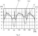
- Figure 2 shows various time-dependent courses of measured values when operating a weaving machine.
- the solid line shows the course of the warp thread tensile force 10 or the warp thread tension 10 (cN per thread) over a period of several weaving cycles.
- the sharp tips 10.1, 10.2 each mark a blade stop. Between two sheet stops in each case one can also see increases in the warp thread tension 10, which, however, are less jerky.
- the jerky acceleration which the warp threads 1 experience when the sheet is stopped, results in a jerky increase in the warp thread tension 10 if the deflecting element 2 does not react with a similar rapid compensating movement.
- the movement of the deflecting element 12 when pivoting about the articulation point in the machine frame 6 is shown as a dashed line in the same diagram.
- the recorded course 12 corresponds to the path of the deflecting element 2 in the area of the thread support of the warp threads 1; in Figure 1 this movement is shown with a double arrow 12.
- the deflecting element 2 is also moved approximately synchronously with the increase in the warp thread tension 10 in the area of the shed changing operations. A further increase in the warp thread tension 10 is thus prevented. This is done by moving the deflecting element 2 as a result of the increasing warp thread tension 10 starting from a rest position by approximately + 2 mm in the direction of the air bellows 5.
- the course of the warp thread tension 10 has minimum values which result from the fact that the warp threads 1 pass through the weaving machine at this point in time without any significant upward and downward deflection; the warp threads 1 form a closed compartment. At this moment, therefore, significantly lower warp thread tensile forces 10 act on the deflecting element 2. As a result, the deflecting element 2 is deflected to the rear, counter to the running direction of the warp threads 1, due to the spring forces of the air bellows 5 - it makes a movement of approx. - 2 mm.
- the inertial forces which oppose a rapid movement of the deflecting element 2, can be increased or decreased according to the invention by exchanging, removing or adding additional masses 8.
- the speed of the weaving machine i.e. to consider the time for a weaving cycle.
- the subject formation and the blade stop result in higher accelerations of the elements involved from the outset.
- These higher accelerations lead to correspondingly higher inertial forces in the case of mass-bearing elements - also in the case of deflection element 2.
- These higher inertial forces must be applied via the warp threads 1.
- a change in speed therefore leads to a change in inertial forces even with unchanged mass ratios.
- Warp threads 2nd Deflecting element 3rd Device for monitoring the warp threads 4th Support element 5 Air bellows 6 Machine frame of the weaving machine 7 Screw connection 8th Additional mass 10th Warp tension or warp tension 10.1, 10.2 Extreme values in the course of the warp thread tension 11 Movement of the warp threads when changing the tray 12 Movement of the deflecting element
Landscapes
- Engineering & Computer Science (AREA)
- Textile Engineering (AREA)
- Looms (AREA)
Description
- Die vorliegende Erfindung betrifft ein Verfahren zur Veränderung des dynamischen Verhaltens eines Streichbalkens einer Webmaschine sowie eine Webmaschine mit einem Streichbalken, der an die Ausführung eines solchen Verfahrens angepasst ist.
- Bei Webmaschinen sind im Stand der Technik Einrichtungen zum Umlenken von Kettfäden bekannt, die als Streichbalken oder Streichbaum bezeichnet werden.
- Eine derartige Vorrichtung zeigt zum Beispiel die
DE 10 2006 061 376 A1 . Diese betrifft einen Streichbaum für eine Webmaschine, bei dem Kettfadenbewegungen in Kettrichtung durch ein schwingfähig auf einer masseoptimierten Blattfeder angeordnetes Fadenumlenkelement ausgeglichen werden. - Die erwähnte Masseoptimierung zielt dabei im Stand der Technik darauf, das dynamische Verhalten des Streichbaums bei hohen Webgeschwindigkeiten so zu gestalten, dass möglichst geringe Kettfadenzugkräfte auftreten. Dies wird durch eine geringe träge Masse des Fadenumlenkelements und eine geringe träge Masse der Blattfeder erreicht.
- Die
WO 2012031802 A2 beschreibt einen Streichbaum zum Führen von Kettfäden mit einem Umlenkelement, das über ein elastisches Element an der Webmaschine abgestützt ist. Auch hier wird die Aufgabe beschrieben, möglichst geringe träge Massen am Fadenumlenkelement vorzusehen, um die Kettfadenbelastung gering zu halten. - Die
DE 1 138 715 A offenbart einen Streichbalken, der in Spannhebeln drehbar gelagert ist, die um eine feste Achse am Maschinengestell verschwenkbar sind und unter der Wirkung eines Kraftspeichers zum Andrücken des Spannbalkens an die Kettfäden stehen. Hierbei weist wenigstens eines der in den Spannhebeln befindlichen Streichbalkenlager eine Bremsvorrichtung zum gleichzeitigen Dämpfen der Schwingungen in der Eigendrehung und in der Verschwenkbewegung des Streichbalkens auf. Auf diese Weise wird das dynamische Verhalten des Streichbalkens durch Änderung von Hebelverhältnissen geregelt. - Bei der Verwendung derartiger Streichbaumeinrichtungen hat sich nun herausgestellt, dass eine möglichst geringe Kettfadenbelastung nicht für alle Webbedingungen und nicht für alle Gewebe sinnvoll ist. Speziell bei technischen Geweben mit hoher Schussdichte, also bei hoher Anzahl von Schussfäden in einer vorgegebenen Gewebelänge, zeigt sich, dass zumindest in einer bestimmten Phase des Webprozesses höhere Kettfadenzugkräfte bzw. Kettfadenspannungen günstig sind. Das ist die Phase, in der ein Schussfaden nach seinem Eintrag in das Webfach von einem Webblatt an die Kante bzw. den Bindepunkt des schon vorhandenen Gewebes angeschlagen wird. Wenn eine hohe Schussdichte, also eine hohe Anzahl von Schussfäden in einer vorgegebenen Gewebelänge, erzielt werden soll, ist zumindest beim Blattanschlag eine höhere Kettfadenzugkraft oder Kettfadenspannung günstiger, weil dann der Bindepunkt weniger ausweicht, wenn ein neuer Schussfaden durch das Webblatt an den Bindepunkt angeschlagen wird. Dadurch wird erreicht, dass aufeinanderfolgende Schussfäden im Gewebe sehr dicht aneinander liegen.
- Auf der anderen Seite soll die Kettfadenspannung in den anderen Phasen des Webprozesses nicht unnötig hoch sein, wie bereits im Stand der Technik eingehend erläutert. Dies gilt vor allem für die Phase des Fachwechsels, der zwischen zwei Blattanschlägen erfolgt. Je nach Muster des Gewebes erfolgt dabei ein Wechsel von allen oder mehreren Kettfäden aus dem Oberfach in das Unterfach und umgekehrt. Bei diesem Fachwechsel werden die Kettfäden geometrisch aus ihrem geraden Verlauf durch die Webmaschine ausgelenkt. Diese Auslenkung erfolgt dadurch, dass die Kettfäden von Weblitzen vertikal nach oben oder unten verschoben werden. Dabei werden die Kettfäden in den Litzen auf Reibung beansprucht. Es ist vorteilhaft zur Vermeidung von Fadenbrüchen, wenn bei diesem Fachwechsel möglichst geringe Kettfadenspannungen vorliegen.
- Es zeigt sich also, dass es vorteilhaft wäre, für bestimmte Gewebe zumindest während des Blattanschlags kurzzeitig höhere Kettfadenspannungen zu erzeugen, während es für andere Gewebe sinnvoll ist, auch beim Blattanschlag mit geringen Kettfadenspannungen zu arbeiten.
- Es ergibt sich also die Aufgabe, zumindest beim Blattanschlag einer Webmaschine bei unterschiedlichen Gewebearten mit unterschiedlichen, an die Gewebeart angepassten Kettfadenspannungen arbeiten zu können.
- Die Aufgabe wird durch ein Verfahren und eine Webmaschine gemäß den unabhängigen Ansprüchen gelöst.
- Das Verfahren zur Veränderung des dynamischen Verhaltens eines Streichbalkens einer Webmaschine betrifft einen Streichbalken mit mindestens einem Umlenkelement zum Umlenken von Kettfäden. Das Umlenkelement kann zum Beispiel aus einem durchgehenden gebogenen Blech bestehen, dessen Längsachse quer zur Richtung der Kettfäden verläuft. Die Kettfäden werden in der Regel ausgehend vom Kettbaum über das Umlenkelement des Streichbalkens zu den Elementen der Fachbildung der Webmaschine geführt.
- Zwar ergeben sich Unterschiede im dynamischen Verhalten des Streichbalkens auch schon bei geringen Unterschieden der am Umlenkelement wirksamen trägen Masse. Gemäß der Erfindung ist jedoch vorgesehen, dass die wirksame träge Masse um einen Faktor vergrößert oder verkleinert wird, der zwischen 1,5 und 8 liegt, vorzugsweise um Faktoren zwischen 2 und 5 - zum Beispiel 2,5 oder 3 oder 4. Mit einem Sortiment verschiedener Zusatzmassen in entsprechender Abstufung ist das dynamische Verhalten an die verschiedensten Anforderungen z.B. Schussdichten oder Drehzahlen anpassbar.
- Anstelle eines einzigen Umlenkelements sind natürlich auch mehrere über die Breite der Webmaschine verteilte Umlenkelemente möglich - zum Beispiel mehrere an die Gewebebreite angepasste Blechelemente.
- Das Umlenkelement ist über ein oder mehrere Federelemente mit einem Maschinengestell der Webmaschine derartig verbunden, dass beim Aufbringen von Kräften, die eine Beschleunigung bzw. eine Bewegung des Umlenkelements gegenüber dem Maschinengestell verursachen, Trägheitskräfte und Federkräfte an dem Umlenkelement wirksam werden. Beschleunigungskräfte werden im Betrieb der Webmaschine durch die Kettfäden auf das Umlenkelement ausgeübt.
- Bei den Trägheitskräften handelt es sich in erster Linie um die Kräfte, die infolge der Beschleunigung der trägen Masse des Umlenkelements auftreten. Zu dieser trägen Masse können auch weitere Bauteile gehören, die an dem Umlenkelement befestigt oder mit diesem derartig verbunden sind, dass sie bei einer Bewegung bzw. Auslenkung des Umlenkelements mitbewegt werden.
- Die Federkräfte entstehen durch eine Auslenkung des Umlenkelements mit dem zugehörigen Federelement aus einer Ruhelage in eine ausgelenkte Lage. Eine derartige Auslenkung aus der Ruhelage in eine ausgelenkte Lage erfolgt in der Regel bereits durch die Kettfäden, die unter Spannung über das Umlenkelement geführt werden. Als Federelemente kommen zum Beispiel Blattfedern zum Einsatz, die sich an ihrem einen Ende am Maschinenrahmen der Webmaschine abstützen und die an ihrem anderen Ende das Umlenkelement tragen. Denkbar ist jedoch auch eine Anordnung, bei der sich das Umlenkelement beweglich am Maschinenrahmen abstützt, zum Beispiel in einem Gelenk, wobei zusätzlich ein Federelement zwischen Umlenkelement und Maschinenrahmen derartig angeordnet ist, dass bei einer Auslenkung des Umlenkelements ein Ende der Feder ausgelenkt wird. Als Federn kommen Blattfedern, Torsionsfeder, Schraubenfedern oder auch Luftfedern in Frage.
- Die Erfindung ist dadurch gekennzeichnet, dass die bei einer Beschleunigung des Umlenkelements wirksame träge Masse verändert wird, um das dynamische Verhalten des Streichbalkens an veränderte Webbedingungen anzupassen. Dies geschieht in der Weise, dass Teile des Umlenkelements oder andere Bauteile, die mit dem Umlenkelement verbunden sind, ausgetauscht, entfernt oder ergänzt werden.
- Durch eine Veränderung der trägen Masse des Umlenkelements wird das dynamische Verhalten des Streichbalkens bei kurzen ruckartigen Beschleunigungsvorgängen - zum Beispiel beim Blattanschlag - stärker beeinflusst als bei langsamen, eher sinusförmig verlaufenden Beschleunigungsvorgängen - zum Beispiel beim Fachwechsel.
- Dies ist besonders wichtig, um zur Erzielung höherer Kettfadenspannungen beim Blattanschlag einen höheren Widerstand des Umlenkelements zu erreichen, ohne die Kettfadenspannung im Bereich des Fachwechsels unnötig zu erhöhen; das heißt ohne höhere Beanspruchung der Kettfäden beim Fachwechsel.
- Bei Geweben mit weniger hoher Schussdichte kann dann umgekehrt durch Reduzieren der wirksamen trägen Masse die Kettfadenbelastung über den gesamten Bereich des Webzyklus (Blattanschlag und Fachwechsel) gering gehalten werden, weil das leichtere Umlenkelement den Beschleunigungsvorgängen weniger Widerstand entgegensetzt.
- In einer ersten Verfahrensausführung ist daher vorgesehen, dass durch einen Austausch oder eine Ergänzung von Teilen die an dem Umlenkelement wirksame träge Masse vergrößert wird, wenn die Webmaschine von einem Gewebe mit niedrigerer Schussdichte auf ein Gewebe mit höherer Schussdichte umgestellt wird.
- Die vergrößerte träge Masse bewirkt einen größeren Widerstand des Umlenkelements gegen ruckartige Bewegungen. Das führt dazu, dass beim - ruckartigen - Blattanschlag der Webmaschine nun in den Kettfäden temporär höhere Kettfadenspannungen auftreten. Diese temporär höheren Kettspannungen beim Blattanschlag sind Voraussetzung für die Erzeugung eines Gewebes mit höherer Schussdichte.
- In einer zweiten Verfahrensausführung ist vorgesehen, dass durch einen Austausch oder ein Entfernen von Teilen die an dem Umlenkelement wirksame träge Masse verkleinert wird, wenn die Webmaschine von einem Gewebe mit höherer Schussdichte auf ein Gewebe mit niedrigerer Schussdichte umgestellt wird.
- Die verringerte träge Masse bewirkt einen geringeren Widerstand des Umlenkelements gegen ruckartige Bewegungen. Das führt dazu, dass beim Blattanschlag der Webmaschine nun in den Kettfäden im Vergleich zu vorher geringere Kettfadenspannungen und damit geringere Beanspruchungen der Kettfäden auftreten.
- Ein weiterer Aspekt der Erfindung betrifft eine Webmaschine mit einem Streichbalken mit mindestens einem Umlenkelement zum Umlenken von Kettfäden entsprechend dem unabhängigen Vorrichtungsanspruch. Das Umlenkelement ist über ein oder mehrere Federelemente mit der Webmaschine derartig verbunden ist, dass beim Aufbringen von Kräften und Bewegungen über die Kettfäden Trägheitskräfte und Federkräfte an dem Umlenkelement wirksam werden. Derartige Beschleunigungskräfte werden im Betrieb der Webmaschine durch die Kettfäden auf das Umlenkelement ausgeübt.
- Bei den Trägheitskräften handelt es sich in erster Linie um die Kräfte, die infolge der Beschleunigung der trägen Masse des Umlenkelements auftreten. Zu dieser trägen Masse können auch weitere Bauteile gehören, die an dem Umlenkelement befestigt sind.
- Die Federkräfte entstehen durch eine Auslenkung des Umlenkelements mit dem zugehörigen Federelement aus einer Ruhelage in eine ausgelenkte Lage. Eine derartige Auslenkung aus der Ruhelage in eine ausgelenkte Lage erfolgt in der Regel bereits durch die Kettfäden, die unter Spannung über das Umlenkelement geführt werden. Als Federelemente kommen zum Beispiel Blattfedern zum Einsatz, die sich an ihrem einen Ende am Maschinenrahmen der Webmaschine abstützen und die an ihrem anderen Ende das Umlenkelement tragen. Denkbar ist jedoch auch eine Anordnung, bei der sich das Umlenkelement beweglich am Maschinenrahmen abstützt, zum Beispiel in einem Gelenk, wobei zusätzlich ein Federelement zwischen Umlenkelement und Maschinenrahmen derartig angeordnet ist, dass bei einer Auslenkung des Umlenkelements auch das eine Ende der Feder ausgelenkt wird. Als Federn kommen Blattfedern, Torsionsfedern, Schraubenfedern oder auch Luftfedern in Frage.
- Die Webmaschine ist erfindungsgemäß dadurch gekennzeichnet, dass die an dem Umlenkelement wirksame träge Masse veränderbar ist, um das dynamische Verhalten des Streichbalkens an veränderte Webbedingungen anzupassen. Diese Veränderbarkeit ist dadurch gegeben, dass Teile des Umlenkelements oder Teile, die mit dem Umlenkelement verbunden sind, austauschbar, entfernbar oder ergänzbar ausgeführt sind. Hierbei ist die Erfindung gekennzeichnet durch ein Sortiment von verschiedenen Umlenkelementen oder Zusatzmassen, mit denen die an dem Umlenkelement wirksame träge Masse um einen Faktor 1,5 - 8 vergrößerbar oder verkleinerbar ist, vorzugsweise um Faktoren zwischen 2 und 5 - zum Beispiel 2,5 oder 3 oder 4.
- Als Ausgangsbasis für eine Webmaschine gemäß der vorliegenden Erfindung hat sich eine Ausführung bewährt, bei der das Umlenkelement als gebogenes Blech ausgeführt ist. Wie bereits im Stand der Technik gezeigt wurde, kann mit einem derartigen Blech ein sehr massearmes Umlenkelement realisiert werden, das Änderungen der Kettfadenspannung rasch folgen kann, ohne dass größere Erhöhungen der Kettfadenspannung verursacht werden.
- Eine besonders vorteilhafte Ausführung der erfindungsgemäßen Webmaschine ergibt sich durch die Verwendung von mindestens einer Zusatzmasse, die mit dem Umlenkelement lediglich kraftschlüssig über eine Klemmverbindung verbunden ist. Diese Variante ermöglicht eine einfachere Montage. Es müssen keine Schrauben entfernt, sondern lediglich eine Klemmung gelöst werden.
- Prinzipiell sind verschiedene Formen von Zusatzmassen denkbar, zum Beispiel Stäbe oder Elemente aus Flachmaterial, die über die Breite der Webmaschine verteilt am Umlenkelement angebracht werden. Am günstigsten ist jedoch die Verwendung von Rohren als Zusatzmassen oder auch Rohre als Umlenkelement. Es können Rohre mit verschiedenen Durchmessern und/oder verschiedenen Wandstärken vorgesehen werden. Rohre lassen sich - drehbar oder feststehend gelagert - als Umlenkelement verwenden oder über eine lösbare Verbindung - zum Beispiel eine Klemmung - mit einem Umlenkelement, das zum Beispiel als gebogenes Blech ausgeführt ist, verbinden. Mehrere Rohre können auch ineinander gesteckt und damit platzsparend in Art eines Baukastens miteinander kombiniert werden.
- Es zeigen:
- Figur 1
- eine Schnittansicht einer Ausführungsform der erfindungsgemäßen Webmaschine mit Blick in Schussrichtung, und
- Figur 2
- ein Diagramm der Kettspannung und der Bewegung des Umlenkelements beim Betrieb einer Webmaschine.
-
Figur 1 zeigt eine Ausführungsform der erfindungsgemäßen Webmaschine in einer Schnittansicht mit Blickrichtung in Schussrichtung auf den hinteren Teil der Maschine. Ausgehend von einem nicht dargestellten Kettbaum werden Kettfäden 1 um ein Umlenkelement 2 herum geführt und von da aus - über eine Vorrichtung zur Überwachung der Kettfäden 3 - dem vorderen Teil der Webmaschine und den Elementen für die Fachbildung und den Blattanschlag zugeführt. - Das Umlenkelement 2 ist im vorliegenden Beispiel als gebogenes Blech ausgeführt. Es ist vorliegend mit einem Stützelement 4 in Form eines gebogenen Blechs verschraubt, das an seinem einen Ende mit einem Luftbalg 5 in Verbindung steht, während das andere Ende an einem Gelenkpunkt im Maschinengestell der Webmaschine 6 abgestützt ist.
- Der Luftbalg 5 bildet hier ein Federelement, über welches das Umlenkelement 2 mit der Webmaschine derartig verbunden ist, dass beim Aufbringen von Kräften über die Kettfäden 1 auf das Umlenkelement 2 Federkräfte am Umlenkelement 2 wirksam werden.
- Die Größe dieser Federkräfte hängt dabei von der Höhe des Luftdrucks in dem Luftbalg 5 ab. Statt des Luftbalgs 5 könnten natürlich auch rein mechanische Federelemente mit entsprechend angepasster Elastizität bzw. Federsteifigkeit vorgesehen werden. So könnte zum Beispiel das Stützelement 4 als Blattfeder ausgebildet sein, deren unteres Ende im Gestell der Webmaschine 6 nicht gelenkig, sondern fest eingespannt ist.
- Um die Vorgänge am Streichbalken im Betrieb der Webmaschine überwachen zu können, ist es sinnvoll, am Umlenkelement 2 selber oder am Stützelement 4 oder zwischen der Feder 5 und dem Maschinengestell 6 einen Sensor - zum Beispiel einen induktiven Wegsensor - anzubringen.
- Das Stützelement 4 und das Umlenkelement 2 sind über eine Schraubverbindung 7 so miteinander verbunden, dass zwischen Umlenkelement 2 und Stützelement 4 eine rohrförmige Zusatzmasse 8 einklemmbar ist. Natürlich sind auch andere Formen der Zusatzmasse 8 möglich - z.B. Stäbe aus Vollmaterial oder auch Elemente mit rechteckigem Querschnitt. Durch Lösen der Klemmung 2, 4, 7 kann die Zusatzmasse 8 entfernt oder durch eine andere ersetzt werden.
- Diese Zusatzmasse 8 wird bei Bewegungen des Umlenkelements 2 mitbewegt und verursacht daher beim Einwirken von Beschleunigungskräften auf das Umlenkelement 2 mehr oder weniger große zusätzliche Trägheitskräfte. Die Trägheitskräfte wirken der Beschleunigung des Umlenkelements 2 entgegen. Derartige Beschleunigungen werden beim Betrieb der Webmaschine durch Kräfte erzeugt, die über die Kettfäden 1 auf das Umlenkelement 2 wirken. Diese Kräfte und die daraus folgenden Bewegungen des Umlenkelements 2 werden in den Kettfäden 1 durch die Fachwechselvorgänge und den Blattanschlag der Webmaschine verursacht.
-
Figur 2 zeigt verschiedene zeitabhängige Verläufe von Messwerten beim Betrieb einer Webmaschine. - Die durchgezogene Linie zeigt den Verlauf der Kettfadenzugkraft 10 bzw. der Kettfadenspannung 10 (cN pro Faden) über einen Zeitraum von mehreren Webzyklen. Die scharfen Spitzen 10.1, 10.2 markieren dabei jeweils einen Blattanschlag. Zwischen jeweils zwei Blattanschlägen erkennt man ebenfalls Anstiege der Kettfadenspannung 10, die jedoch weniger ruckartig ausgebildet sind.
- In diesen Bereichen findet jeweils ein Fachwechsel statt, in dem ein Teil der Kettfäden 1 von oben nach unten wechselt, während ein andere Teil der Kettfäden 1 gegenläufig bewegt wird - Doppelpfeil 11 in
Figur 1 . - Die ruckartige Beschleunigung, die die Kettfäden 1 beim Blattanschlag erfahren, wirkt sich in einem ruckartigen Anstieg der Kettfadenspannung 10 aus, wenn das Umlenkelement 2 nicht mit einer ähnlich raschen Ausgleichsbewegung reagiert. Zum Vergleich ist als gestrichelte Linie im gleichen Diagramm die Bewegung des Umlenkelements 12 bei einem Verschwenken um den Gelenkpunkt im Maschinengestell 6 dargestellt. Der aufgezeichnete Verlauf 12 entspricht dem Weg des Umlenkelements 2 im Bereich der Fadenauflage der Kettfäden 1; in
Figur 1 ist diese Bewegung mit einem Doppelpfeil 12 dargestellt. - Im vorliegenden Fall sieht man, dass das Umlenkelement 2 im Bereich der Fachwechselvorgänge in etwa synchron mit dem Anstieg der Kettfadenspannung 10 mitbewegt wird. Eine weitere Erhöhung der Kettfadenspannung 10 wird damit verhindert. Dies geschieht, indem das Umlenkelement 2 infolge der ansteigenden Kettfadenspannung 10 ausgehend von einer Ruhelage um ca. + 2 mm in Richtung auf den Luftbalg 5 bewegt wird.
- Kurz vor den Spannungsspitzen 10.1, 10.2 hat der Verlauf der Kettfadenspannung 10 Minimalwerte, die dadurch entstehen, dass die Kettfäden 1 zu diesem Zeitpunkt die Webmaschine ohne nennenswerte Auslenkung nach oben und nach unten durchlaufen; die Kettfäden 1 bilden dabei ein geschlossenes Fach. Es wirken daher in diesem Moment deutlich geringere Kettfadenzugkräfte 10 auf das Umlenkelement 2. Das führt dazu, dass infolge der Federkräfte des Luftbalgs 5 das Umlenkelement 2 nach hinten, entgegen gesetzt zur Laufrichtung der Kettfäden 1 ausgelenkt wird - es macht dabei eine Bewegung von ca. - 2 mm.
- Man sieht in
Figur 2 weiterhin, dass beim nun folgenden Blattanschlag die Bewegung des Umlenkelements 12 qualitativ einen anderen Verlauf hat als der Verlauf der Kettfadenspannung 10. Infolge der trägen Masse wird das Umlenkelement 2 nicht so rasch in Bewegung gesetzt, wie es zum Ausgleich des sehr raschen Anstiegs der Kettfadenspannung 10 beim Blattanschlag erforderlich wäre. Die Folge ist die inFigur 2 dargestellte Spannungsspitze der Kettfadenspannung 10.2, die in vielen Fällen unerwünscht ist, bei manchen Geweben mit hoher Schussdichte jedoch zwingend erforderlich ist, um die gewünschte Schussdichte überhaupt zu erreichen. - Die Trägheitskräfte, die einer raschen Bewegung des Umlenkelements 2 entgegen stehen, können erfindungsgemäß durch Austausch, Entfernung oder Ergänzung von Zusatzmassen 8 vergrößert oder verkleinert werden. Neben der gewünschten Schussdichte ist dabei auch die Drehzahl der Webmaschine, d.h. die Zeit für einen Webzyklus zu berücksichtigen. Bei höheren Drehzahlen - also sehr kurzen Webzyklen - ergeben sich durch die Fachbildung und den Blattanschlag von vorne herein höhere Beschleunigungen der beteiligten Elemente. Diese höheren Beschleunigungen führen bei massebehafteten Elementen - also auch beim Umlenkelement 2 - zu entsprechend höheren Trägheitskräften. Diese höheren Trägheitskräfte müssen über die Kettfäden 1 aufgebracht werden. Eine Veränderung der Drehzahl führt also schon bei unveränderten Masseverhältnissen zu einer Veränderung der Trägheitskräfte. Bei niedriger Drehzahl und hoher Schussdichte kann es jedoch erforderlich werden, die Trägheitskräfte durch Anbau zusätzlicher Massen am Umlenkelement 2 zu erhöhen.
- In der Praxis ist zum Beispiel bei einem Gewebe mit einer Schussdichte von 24 S/cm bei einer Drehzahl der Webmaschine von 600 S/min eine Zusatzmasse in der Größenordnung von 10 kg pro Meter Gewebebreite mit gutem Erfolg eingesetzt worden.
- Soll mit einer derartig ausgestatteten Maschine anschließend ein Gewebe produziert werden, bei dem hohe Kettfadenspannungsspitzen 10.1, 10.2 nicht erwünscht sind, können erfindungsgemäß Zusatzmassen 8 entfernt oder gegen solche mit geringerer Masse ausgetauscht werden.
- Es hat sich gezeigt, dass ein Sortiment von Zusatzmassen 8 für die meisten Fälle ausreichend ist, wenn damit stufenweise Massenvergrößerungen oder -verringerungen um Faktoren von 2 bis 5 erzielbar sind. In wenigen Sonderfällen Fällen können auch kleinere oder sogar größere Abstufungen der Massen notwendig werden - also z.B. solche um den Faktor 1,5 oder sogar um Faktoren zwischen 5 und 8. Damit sind dann anwendungsabhängig Anpassungen in weiten Bereichen möglich.
Bezugszeichen 1 Kettfäden 2 Umlenkelement 3 Vorrichtung zum Überwachen der Kettfäden 4 Stützelement 5 Luftbalg 6 Maschinengestell der Webmaschine 7 Schraubverbindung 8 Zusatzmasse 10 Kettfadenzugkraft bzw. Kettfadenspannung 10.1, 10.2 Extremwerte im Verlauf der Kettfadenzugkraft 11 Bewegung der Kettfäden beim Fachwechsel 12 Bewegung des Umlenkelements
Claims (7)
- Verfahren zur Veränderung des dynamischen Verhaltens eines Streichbalkens einer Webmaschine, wobei der Streichbalken mindestens ein Umlenkelement (2) zum Umlenken von Kettfäden (1) enthält, wobei das Umlenkelement (2) über ein oder mehrere Federelemente mit der Webmaschine derartig verbunden ist, dass beim Aufbringen von Kräften über die Kettfäden (1) auf das Umlenkelement (2) Trägheitskräfte und Federkräfte an dem Umlenkelement (2) wirksam werden, wobei die dabei an dem Umlenkelement (2) wirksame träge Masse verändert wird, um das dynamische Verhalten des Streichbalkens an veränderte Webbedingungen anzupassen, indem Teile des Umlenkelements (2) oder Teile, die mit dem Umlenkelement (2) verbunden sind,
ausgetauscht, entfernt oder ergänzt werden, dadurch gekennzeichnet, dass die an dem Umlenkelement (2) wirksame träge Masse um einen Faktor vergrößert oder verkleinert wird, der zwischen 1,5 und 8 liegt, vorzugsweise um einen Faktor zwischen 2 und 5. - Verfahren nach Anspruch 1, dadurch gekennzeichnet, dass durch einen Austausch oder eine Ergänzung von Teilen die an dem Umlenkelement (2) wirksame träge Masse vergrößert wird, wenn die Webmaschine von einem Gewebe mit niedrigerer Schussdichte auf eine Gewebe mit höherer Schussdichte umgestellt wird.
- Verfahren nach Anspruch 1, dadurch gekennzeichnet, dass durch einen Austausch oder ein Entfernen von Teilen die an dem Umlenkelement (2) wirksame träge Masse verkleinert wird, wenn die Webmaschine von einem Gewebe mit höherer Schussdichte auf eine Gewebe mit niedrigerer Schussdichte umgestellt wird.
- Webmaschine mit einem Streichbalken, der mindestens ein Umlenkelement (2) zum Umlenken von Kettfäden (1) enthält, wobei das Umlenkelement (2) über ein oder mehrere Federelemente mit der Webmaschine derartig verbunden ist, dass beim Aufbringen von Kräften und Bewegungen über die Kettfäden (1) Trägheitskräfte und Federkräfte an dem Umlenkelement (2) wirksam werden, gekennzeichnet durch ein Sortiment von verschiedenen Umlenkelementen (2) oder Zusatzmassen (8), um Teile des Umlenkelements (2) oder Teile, die mit dem Umlenkelement (2) verbunden sind, auszutauschen, zu entfernen oder zu ergänzen und somit die an dem Umlenkelement (2) wirksame träge Masse um einen Faktor 1,5 - 8 zu vergrößern oder zu verkleinern, vorzugsweise um einen Faktor 2 - 5, um das dynamische Verhalten des Streichbalkens an veränderte Webbedingungen anzupassen.
- Webmaschine nach Anspruch 4, dadurch gekennzeichnet, dass das Umlenkelement (2) als gebogenes Blech oder als Rohr ausgeführt ist.
- Webmaschine nach Anspruch 4 oder 5, dadurch gekennzeichnet, dass zum Verändern der an dem Umlenkelement (2) wirksamen trägen Masse mindestens eine Zusatzmasse (8) mit dem Umlenkelement (2) über eine lösbare Klemmverbindung (4, 7) verbunden ist.
- Webmaschine nach Anspruch 6, dadurch gekennzeichnet, dass mindestens eine Zusatzmasse (8) als Rohr ausgeführt ist.
Applications Claiming Priority (2)
| Application Number | Priority Date | Filing Date | Title |
|---|---|---|---|
| DE102016216610.7A DE102016216610B3 (de) | 2016-09-02 | 2016-09-02 | Verfahren und Vorrichtung zur Veränderung des dynamischen Verhaltens eines Streichbalkens einer Webmaschine |
| PCT/EP2017/070337 WO2018041592A1 (de) | 2016-09-02 | 2017-08-10 | Verfahren und vorrichtung zur veränderung des dynamischen verhaltens eines streichbalkens einer webmaschine |
Publications (2)
| Publication Number | Publication Date |
|---|---|
| EP3507405A1 EP3507405A1 (de) | 2019-07-10 |
| EP3507405B1 true EP3507405B1 (de) | 2020-06-17 |
Family
ID=59686925
Family Applications (1)
| Application Number | Title | Priority Date | Filing Date |
|---|---|---|---|
| EP17755454.0A Active EP3507405B1 (de) | 2016-09-02 | 2017-08-10 | Verfahren und vorrichtung zur veränderung des dynamischen verhaltens eines streichbalkens einer webmaschine |
Country Status (6)
| Country | Link |
|---|---|
| EP (1) | EP3507405B1 (de) |
| JP (1) | JP2019529730A (de) |
| CN (1) | CN109642363B (de) |
| DE (1) | DE102016216610B3 (de) |
| TW (1) | TW201812129A (de) |
| WO (1) | WO2018041592A1 (de) |
Cited By (1)
| Publication number | Priority date | Publication date | Assignee | Title |
|---|---|---|---|---|
| CN111793881A (zh) * | 2020-06-29 | 2020-10-20 | 苏州优百纺织有限公司 | 一种纺织机用进线夹持装置 |
Families Citing this family (4)
| Publication number | Priority date | Publication date | Assignee | Title |
|---|---|---|---|---|
| DE102018212847B3 (de) | 2018-08-01 | 2019-10-10 | Lindauer Dornier Gesellschaft Mit Beschränkter Haftung | Vorrichtung zum Einstellen der Kettspannung von Kettfäden |
| DE102018212932B3 (de) | 2018-08-02 | 2019-06-13 | Lindauer Dornier Gesellschaft Mit Beschränkter Haftung | Vorrichtung zum Führen von Kettfäden in einer Webmaschine |
| DE102018218294B3 (de) * | 2018-10-25 | 2020-03-05 | Lindauer Dornier Gesellschaft Mit Beschränkter Haftung | Vorrichtung zur Messung der Kettspannung in einer Webmaschine sowie Webmaschine |
| CN119421974A (zh) * | 2022-06-02 | 2025-02-11 | 桑贾伊·阿南·库尔库特 | 用于在织机的张力传感机构中赋予瞬时刚度的系统及其方法 |
Family Cites Families (10)
| Publication number | Priority date | Publication date | Assignee | Title |
|---|---|---|---|---|
| DE1138715B (de) * | 1956-04-13 | 1962-10-25 | Sulzer Ag | Webmaschine |
| BE792485A (fr) * | 1971-12-10 | 1973-06-08 | Sulzer Ag | Barre de deviation des fils de chaine d'un metier a tisser |
| DD100753A5 (de) * | 1972-11-30 | 1973-10-05 | ||
| DE3346030A1 (de) * | 1983-12-20 | 1985-06-20 | Institute für Textil- und Faserforschung Stuttgart, 7306 Denkendorf | Webmaschine |
| DE4427129C2 (de) * | 1994-07-30 | 1998-07-30 | Dornier Gmbh Lindauer | Spanneinheit für die Webkette einer Webmaschine |
| DE102006061376A1 (de) * | 2006-12-23 | 2008-06-26 | Lindauer Dornier Gmbh | Streichbaum für eine Webmaschine |
| DE202010004517U1 (de) * | 2010-04-01 | 2011-10-05 | Lindauer Dornier Gmbh | Vorrichtung zum Ausgleich von Zugkraftänderungen in Kettfäden an einer Webmaschine |
| BE1019474A3 (nl) * | 2010-09-06 | 2012-07-03 | Picanol Nv | Sleep voor weefmachine. |
| DE102013219942A1 (de) * | 2013-10-01 | 2015-04-02 | Lindauer Dornier Gesellschaft Mit Beschränkter Haftung | Verfahren und Vorrichtung zum Aufbringen von Kräften und Bewegungen auf Kettfäden einer Webmaschine |
| CN204039634U (zh) * | 2014-06-30 | 2014-12-24 | 山东日发纺织机械有限公司 | 一种毛巾织机毛经张力控制装置 |
-
2016
- 2016-09-02 DE DE102016216610.7A patent/DE102016216610B3/de not_active Expired - Fee Related
-
2017
- 2017-08-10 EP EP17755454.0A patent/EP3507405B1/de active Active
- 2017-08-10 CN CN201780053863.7A patent/CN109642363B/zh not_active Expired - Fee Related
- 2017-08-10 WO PCT/EP2017/070337 patent/WO2018041592A1/de not_active Ceased
- 2017-08-10 JP JP2019512305A patent/JP2019529730A/ja active Pending
- 2017-08-14 TW TW106127420A patent/TW201812129A/zh unknown
Non-Patent Citations (1)
| Title |
|---|
| None * |
Cited By (2)
| Publication number | Priority date | Publication date | Assignee | Title |
|---|---|---|---|---|
| CN111793881A (zh) * | 2020-06-29 | 2020-10-20 | 苏州优百纺织有限公司 | 一种纺织机用进线夹持装置 |
| CN111793881B (zh) * | 2020-06-29 | 2021-12-21 | 苏州优众纳米科技有限公司 | 一种纺织机用进线夹持装置 |
Also Published As
| Publication number | Publication date |
|---|---|
| JP2019529730A (ja) | 2019-10-17 |
| EP3507405A1 (de) | 2019-07-10 |
| TW201812129A (zh) | 2018-04-01 |
| WO2018041592A1 (de) | 2018-03-08 |
| CN109642363A (zh) | 2019-04-16 |
| DE102016216610B3 (de) | 2017-11-02 |
| CN109642363B (zh) | 2021-06-25 |
Similar Documents
| Publication | Publication Date | Title |
|---|---|---|
| DE102016216610B3 (de) | Verfahren und Vorrichtung zur Veränderung des dynamischen Verhaltens eines Streichbalkens einer Webmaschine | |
| EP3052686A1 (de) | Verfahren und vorrichtung zum aufbringen von kräften und bewegungen auf kettfäden einer webmaschine | |
| DE2162396C3 (de) | Umlenkbaum für Kettfadenscharen in Webmaschinen | |
| DE10004376A1 (de) | Verfahren zum Herstellen eines Dreher-Grundgewebes auf Webmaschinen | |
| WO2017102407A1 (de) | Linearreibschweissmaschine | |
| DE4102585A1 (de) | Verfahren und drehereinrichtung zur herstellung riffelfester kanten eines doppelgewebes auf einer doppelgreifer-webmaschine | |
| EP1299586B1 (de) | Vorrichtung zum bilden eines drehergewebes | |
| DE3933503A1 (de) | Kettfaden-spannvorrichtung fuer einen webstuhl | |
| EP1440193B1 (de) | Fadenverarbeitendes system | |
| DE2541990B2 (de) | Übernahmegreifer fur Webmaschinen | |
| DE69029219T2 (de) | Verschiebbare Vorrichtung zum Realisieren von mit Schlitzdreherlitze gewebten Kanten auf schützenlosen Webmaschinen | |
| DD283167A5 (de) | Vorrichtung zum fuehren der greiferstangen an einer greiferwebmaschine | |
| DE3216624C2 (de) | Antriebsvorrichtung für Schaftrahmen an Webmaschinen | |
| DE202019101093U1 (de) | Vorrichtung zum Schneiden der Schussfäden in einer Greiferwebmaschine ohne Bildung einer falschen Webkante | |
| WO1999004075A1 (de) | Antriebssystem für wenigstens einen webschaft einer webmaschine | |
| EP4151790B1 (de) | Legebarrenantrieb einer kettenwirkmaschine | |
| EP0273350A2 (de) | Verfahren und Einrichtung zum Führen der Schussfäden bei Webmaschinen | |
| DE3518987A1 (de) | Schusseintragungsvorrichtung fuer webmaschinen mit schwenkbaren blasduesen und verfahren zum pneumatischen eintragen aufeinanderfolgender schusslaengen | |
| DE102007047694B4 (de) | Verfahren zur Ansteuerung der Richträder einer Nadelrichtanordnung und zugehörige Nadelrichtanordnung | |
| EP3980593A1 (de) | VORRICHTUNG ZUM VERGLEICHMÄßIGEN DER BINDEPUNKTLINIE BEIM WEBEN VON FROTTIERGEWEBE | |
| WO2020025411A1 (de) | Vorrichtung zum einstellen der kettspannung von kettfäden | |
| DE498495C (de) | Fadentrennvorrichtung | |
| EP0888470A1 (de) | Stabbreithalter für eine webmaschine | |
| EP1786963A1 (de) | Verfahren zum klemmen von schussf[den, klemmvorrichtung und webmaschine mit wenigstens einer klemmvorrichtung f]r schussf[den | |
| WO2002101132A1 (de) | Verfahren und vorrichtung zum spannen eines kettfadens |
Legal Events
| Date | Code | Title | Description |
|---|---|---|---|
| STAA | Information on the status of an ep patent application or granted ep patent |
Free format text: STATUS: UNKNOWN |
|
| STAA | Information on the status of an ep patent application or granted ep patent |
Free format text: STATUS: THE INTERNATIONAL PUBLICATION HAS BEEN MADE |
|
| PUAI | Public reference made under article 153(3) epc to a published international application that has entered the european phase |
Free format text: ORIGINAL CODE: 0009012 |
|
| STAA | Information on the status of an ep patent application or granted ep patent |
Free format text: STATUS: REQUEST FOR EXAMINATION WAS MADE |
|
| 17P | Request for examination filed |
Effective date: 20190208 |
|
| AK | Designated contracting states |
Kind code of ref document: A1 Designated state(s): AL AT BE BG CH CY CZ DE DK EE ES FI FR GB GR HR HU IE IS IT LI LT LU LV MC MK MT NL NO PL PT RO RS SE SI SK SM TR |
|
| AX | Request for extension of the european patent |
Extension state: BA ME |
|
| DAV | Request for validation of the european patent (deleted) | ||
| DAX | Request for extension of the european patent (deleted) | ||
| GRAP | Despatch of communication of intention to grant a patent |
Free format text: ORIGINAL CODE: EPIDOSNIGR1 |
|
| STAA | Information on the status of an ep patent application or granted ep patent |
Free format text: STATUS: GRANT OF PATENT IS INTENDED |
|
| INTG | Intention to grant announced |
Effective date: 20200204 |
|
| GRAS | Grant fee paid |
Free format text: ORIGINAL CODE: EPIDOSNIGR3 |
|
| GRAA | (expected) grant |
Free format text: ORIGINAL CODE: 0009210 |
|
| STAA | Information on the status of an ep patent application or granted ep patent |
Free format text: STATUS: THE PATENT HAS BEEN GRANTED |
|
| AK | Designated contracting states |
Kind code of ref document: B1 Designated state(s): AL AT BE BG CH CY CZ DE DK EE ES FI FR GB GR HR HU IE IS IT LI LT LU LV MC MK MT NL NO PL PT RO RS SE SI SK SM TR |
|
| REG | Reference to a national code |
Ref country code: GB Ref legal event code: FG4D Free format text: NOT ENGLISH |
|
| REG | Reference to a national code |
Ref country code: CH Ref legal event code: EP |
|
| REG | Reference to a national code |
Ref country code: IE Ref legal event code: FG4D Free format text: LANGUAGE OF EP DOCUMENT: GERMAN |
|
| REG | Reference to a national code |
Ref country code: DE Ref legal event code: R096 Ref document number: 502017005781 Country of ref document: DE |
|
| REG | Reference to a national code |
Ref country code: AT Ref legal event code: REF Ref document number: 1281413 Country of ref document: AT Kind code of ref document: T Effective date: 20200715 |
|
| PG25 | Lapsed in a contracting state [announced via postgrant information from national office to epo] |
Ref country code: SE Free format text: LAPSE BECAUSE OF FAILURE TO SUBMIT A TRANSLATION OF THE DESCRIPTION OR TO PAY THE FEE WITHIN THE PRESCRIBED TIME-LIMIT Effective date: 20200617 Ref country code: GR Free format text: LAPSE BECAUSE OF FAILURE TO SUBMIT A TRANSLATION OF THE DESCRIPTION OR TO PAY THE FEE WITHIN THE PRESCRIBED TIME-LIMIT Effective date: 20200918 Ref country code: NO Free format text: LAPSE BECAUSE OF FAILURE TO SUBMIT A TRANSLATION OF THE DESCRIPTION OR TO PAY THE FEE WITHIN THE PRESCRIBED TIME-LIMIT Effective date: 20200917 Ref country code: LT Free format text: LAPSE BECAUSE OF FAILURE TO SUBMIT A TRANSLATION OF THE DESCRIPTION OR TO PAY THE FEE WITHIN THE PRESCRIBED TIME-LIMIT Effective date: 20200617 Ref country code: FI Free format text: LAPSE BECAUSE OF FAILURE TO SUBMIT A TRANSLATION OF THE DESCRIPTION OR TO PAY THE FEE WITHIN THE PRESCRIBED TIME-LIMIT Effective date: 20200617 |
|
| REG | Reference to a national code |
Ref country code: LT Ref legal event code: MG4D |
|
| REG | Reference to a national code |
Ref country code: NL Ref legal event code: MP Effective date: 20200617 |
|
| PG25 | Lapsed in a contracting state [announced via postgrant information from national office to epo] |
Ref country code: LV Free format text: LAPSE BECAUSE OF FAILURE TO SUBMIT A TRANSLATION OF THE DESCRIPTION OR TO PAY THE FEE WITHIN THE PRESCRIBED TIME-LIMIT Effective date: 20200617 Ref country code: HR Free format text: LAPSE BECAUSE OF FAILURE TO SUBMIT A TRANSLATION OF THE DESCRIPTION OR TO PAY THE FEE WITHIN THE PRESCRIBED TIME-LIMIT Effective date: 20200617 Ref country code: BG Free format text: LAPSE BECAUSE OF FAILURE TO SUBMIT A TRANSLATION OF THE DESCRIPTION OR TO PAY THE FEE WITHIN THE PRESCRIBED TIME-LIMIT Effective date: 20200917 Ref country code: RS Free format text: LAPSE BECAUSE OF FAILURE TO SUBMIT A TRANSLATION OF THE DESCRIPTION OR TO PAY THE FEE WITHIN THE PRESCRIBED TIME-LIMIT Effective date: 20200617 |
|
| PG25 | Lapsed in a contracting state [announced via postgrant information from national office to epo] |
Ref country code: NL Free format text: LAPSE BECAUSE OF FAILURE TO SUBMIT A TRANSLATION OF THE DESCRIPTION OR TO PAY THE FEE WITHIN THE PRESCRIBED TIME-LIMIT Effective date: 20200617 Ref country code: AL Free format text: LAPSE BECAUSE OF FAILURE TO SUBMIT A TRANSLATION OF THE DESCRIPTION OR TO PAY THE FEE WITHIN THE PRESCRIBED TIME-LIMIT Effective date: 20200617 |
|
| PG25 | Lapsed in a contracting state [announced via postgrant information from national office to epo] |
Ref country code: ES Free format text: LAPSE BECAUSE OF FAILURE TO SUBMIT A TRANSLATION OF THE DESCRIPTION OR TO PAY THE FEE WITHIN THE PRESCRIBED TIME-LIMIT Effective date: 20200617 Ref country code: PT Free format text: LAPSE BECAUSE OF FAILURE TO SUBMIT A TRANSLATION OF THE DESCRIPTION OR TO PAY THE FEE WITHIN THE PRESCRIBED TIME-LIMIT Effective date: 20201019 Ref country code: EE Free format text: LAPSE BECAUSE OF FAILURE TO SUBMIT A TRANSLATION OF THE DESCRIPTION OR TO PAY THE FEE WITHIN THE PRESCRIBED TIME-LIMIT Effective date: 20200617 Ref country code: SM Free format text: LAPSE BECAUSE OF FAILURE TO SUBMIT A TRANSLATION OF THE DESCRIPTION OR TO PAY THE FEE WITHIN THE PRESCRIBED TIME-LIMIT Effective date: 20200617 Ref country code: RO Free format text: LAPSE BECAUSE OF FAILURE TO SUBMIT A TRANSLATION OF THE DESCRIPTION OR TO PAY THE FEE WITHIN THE PRESCRIBED TIME-LIMIT Effective date: 20200617 |
|
| PG25 | Lapsed in a contracting state [announced via postgrant information from national office to epo] |
Ref country code: PL Free format text: LAPSE BECAUSE OF FAILURE TO SUBMIT A TRANSLATION OF THE DESCRIPTION OR TO PAY THE FEE WITHIN THE PRESCRIBED TIME-LIMIT Effective date: 20200617 Ref country code: SK Free format text: LAPSE BECAUSE OF FAILURE TO SUBMIT A TRANSLATION OF THE DESCRIPTION OR TO PAY THE FEE WITHIN THE PRESCRIBED TIME-LIMIT Effective date: 20200617 Ref country code: IS Free format text: LAPSE BECAUSE OF FAILURE TO SUBMIT A TRANSLATION OF THE DESCRIPTION OR TO PAY THE FEE WITHIN THE PRESCRIBED TIME-LIMIT Effective date: 20201017 |
|
| REG | Reference to a national code |
Ref country code: DE Ref legal event code: R097 Ref document number: 502017005781 Country of ref document: DE |
|
| PG25 | Lapsed in a contracting state [announced via postgrant information from national office to epo] |
Ref country code: MC Free format text: LAPSE BECAUSE OF FAILURE TO SUBMIT A TRANSLATION OF THE DESCRIPTION OR TO PAY THE FEE WITHIN THE PRESCRIBED TIME-LIMIT Effective date: 20200617 |
|
| PLBE | No opposition filed within time limit |
Free format text: ORIGINAL CODE: 0009261 |
|
| STAA | Information on the status of an ep patent application or granted ep patent |
Free format text: STATUS: NO OPPOSITION FILED WITHIN TIME LIMIT |
|
| PG25 | Lapsed in a contracting state [announced via postgrant information from national office to epo] |
Ref country code: LU Free format text: LAPSE BECAUSE OF NON-PAYMENT OF DUE FEES Effective date: 20200810 Ref country code: DK Free format text: LAPSE BECAUSE OF FAILURE TO SUBMIT A TRANSLATION OF THE DESCRIPTION OR TO PAY THE FEE WITHIN THE PRESCRIBED TIME-LIMIT Effective date: 20200617 |
|
| 26N | No opposition filed |
Effective date: 20210318 |
|
| PG25 | Lapsed in a contracting state [announced via postgrant information from national office to epo] |
Ref country code: SI Free format text: LAPSE BECAUSE OF FAILURE TO SUBMIT A TRANSLATION OF THE DESCRIPTION OR TO PAY THE FEE WITHIN THE PRESCRIBED TIME-LIMIT Effective date: 20200617 |
|
| PG25 | Lapsed in a contracting state [announced via postgrant information from national office to epo] |
Ref country code: FR Free format text: LAPSE BECAUSE OF NON-PAYMENT OF DUE FEES Effective date: 20200817 |
|
| PG25 | Lapsed in a contracting state [announced via postgrant information from national office to epo] |
Ref country code: IE Free format text: LAPSE BECAUSE OF NON-PAYMENT OF DUE FEES Effective date: 20200810 |
|
| PGFP | Annual fee paid to national office [announced via postgrant information from national office to epo] |
Ref country code: CZ Payment date: 20210728 Year of fee payment: 5 Ref country code: IT Payment date: 20210831 Year of fee payment: 5 |
|
| PGFP | Annual fee paid to national office [announced via postgrant information from national office to epo] |
Ref country code: DE Payment date: 20210819 Year of fee payment: 5 Ref country code: BE Payment date: 20210823 Year of fee payment: 5 Ref country code: CH Payment date: 20210824 Year of fee payment: 5 |
|
| GBPC | Gb: european patent ceased through non-payment of renewal fee |
Effective date: 20210810 |
|
| PG25 | Lapsed in a contracting state [announced via postgrant information from national office to epo] |
Ref country code: TR Free format text: LAPSE BECAUSE OF FAILURE TO SUBMIT A TRANSLATION OF THE DESCRIPTION OR TO PAY THE FEE WITHIN THE PRESCRIBED TIME-LIMIT Effective date: 20200617 Ref country code: MT Free format text: LAPSE BECAUSE OF FAILURE TO SUBMIT A TRANSLATION OF THE DESCRIPTION OR TO PAY THE FEE WITHIN THE PRESCRIBED TIME-LIMIT Effective date: 20200617 Ref country code: CY Free format text: LAPSE BECAUSE OF FAILURE TO SUBMIT A TRANSLATION OF THE DESCRIPTION OR TO PAY THE FEE WITHIN THE PRESCRIBED TIME-LIMIT Effective date: 20200617 |
|
| PG25 | Lapsed in a contracting state [announced via postgrant information from national office to epo] |
Ref country code: MK Free format text: LAPSE BECAUSE OF FAILURE TO SUBMIT A TRANSLATION OF THE DESCRIPTION OR TO PAY THE FEE WITHIN THE PRESCRIBED TIME-LIMIT Effective date: 20200617 |
|
| PG25 | Lapsed in a contracting state [announced via postgrant information from national office to epo] |
Ref country code: GB Free format text: LAPSE BECAUSE OF NON-PAYMENT OF DUE FEES Effective date: 20210810 |
|
| REG | Reference to a national code |
Ref country code: DE Ref legal event code: R119 Ref document number: 502017005781 Country of ref document: DE |
|
| REG | Reference to a national code |
Ref country code: CH Ref legal event code: PL |
|
| PG25 | Lapsed in a contracting state [announced via postgrant information from national office to epo] |
Ref country code: LI Free format text: LAPSE BECAUSE OF NON-PAYMENT OF DUE FEES Effective date: 20220831 Ref country code: CZ Free format text: LAPSE BECAUSE OF NON-PAYMENT OF DUE FEES Effective date: 20220810 Ref country code: CH Free format text: LAPSE BECAUSE OF NON-PAYMENT OF DUE FEES Effective date: 20220831 |
|
| REG | Reference to a national code |
Ref country code: BE Ref legal event code: MM Effective date: 20220831 |
|
| PG25 | Lapsed in a contracting state [announced via postgrant information from national office to epo] |
Ref country code: IT Free format text: LAPSE BECAUSE OF NON-PAYMENT OF DUE FEES Effective date: 20220810 Ref country code: DE Free format text: LAPSE BECAUSE OF NON-PAYMENT OF DUE FEES Effective date: 20230301 |
|
| PG25 | Lapsed in a contracting state [announced via postgrant information from national office to epo] |
Ref country code: BE Free format text: LAPSE BECAUSE OF NON-PAYMENT OF DUE FEES Effective date: 20220831 |
|
| REG | Reference to a national code |
Ref country code: AT Ref legal event code: MM01 Ref document number: 1281413 Country of ref document: AT Kind code of ref document: T Effective date: 20220810 |
|
| PG25 | Lapsed in a contracting state [announced via postgrant information from national office to epo] |
Ref country code: AT Free format text: LAPSE BECAUSE OF NON-PAYMENT OF DUE FEES Effective date: 20220810 |