EP3507177B1 - Trottinette pliante anti-cliquetis - Google Patents
Trottinette pliante anti-cliquetis Download PDFInfo
- Publication number
- EP3507177B1 EP3507177B1 EP17847577.8A EP17847577A EP3507177B1 EP 3507177 B1 EP3507177 B1 EP 3507177B1 EP 17847577 A EP17847577 A EP 17847577A EP 3507177 B1 EP3507177 B1 EP 3507177B1
- Authority
- EP
- European Patent Office
- Prior art keywords
- scooter
- knob
- assembly
- deck
- pin
- Prior art date
- Legal status (The legal status is an assumption and is not a legal conclusion. Google has not performed a legal analysis and makes no representation as to the accuracy of the status listed.)
- Active
Links
- 238000000034 method Methods 0.000 claims description 11
- 230000002401 inhibitory effect Effects 0.000 claims description 4
- 230000036961 partial effect Effects 0.000 description 8
- 238000005516 engineering process Methods 0.000 description 5
- 230000000712 assembly Effects 0.000 description 4
- 238000000429 assembly Methods 0.000 description 4
- 239000006260 foam Substances 0.000 description 4
- 238000007373 indentation Methods 0.000 description 3
- 230000000670 limiting effect Effects 0.000 description 3
- 239000000463 material Substances 0.000 description 3
- 230000007935 neutral effect Effects 0.000 description 3
- 230000007246 mechanism Effects 0.000 description 2
- 238000012986 modification Methods 0.000 description 2
- 230000004048 modification Effects 0.000 description 2
- 239000011435 rock Substances 0.000 description 2
- 238000005096 rolling process Methods 0.000 description 2
- 238000000926 separation method Methods 0.000 description 2
- 230000006835 compression Effects 0.000 description 1
- 238000007906 compression Methods 0.000 description 1
- 238000012790 confirmation Methods 0.000 description 1
- 230000000694 effects Effects 0.000 description 1
- 230000006870 function Effects 0.000 description 1
- 230000008676 import Effects 0.000 description 1
- 239000002184 metal Substances 0.000 description 1
- 230000008569 process Effects 0.000 description 1
- 230000002035 prolonged effect Effects 0.000 description 1
- 230000002829 reductive effect Effects 0.000 description 1
- 230000000284 resting effect Effects 0.000 description 1
- 239000007787 solid Substances 0.000 description 1
Images


Classifications
-
- B—PERFORMING OPERATIONS; TRANSPORTING
- B62—LAND VEHICLES FOR TRAVELLING OTHERWISE THAN ON RAILS
- B62K—CYCLES; CYCLE FRAMES; CYCLE STEERING DEVICES; RIDER-OPERATED TERMINAL CONTROLS SPECIALLY ADAPTED FOR CYCLES; CYCLE AXLE SUSPENSIONS; CYCLE SIDE-CARS, FORECARS, OR THE LIKE
- B62K15/00—Collapsible or foldable cycles
- B62K15/006—Collapsible or foldable cycles the frame being foldable
-
- B—PERFORMING OPERATIONS; TRANSPORTING
- B62—LAND VEHICLES FOR TRAVELLING OTHERWISE THAN ON RAILS
- B62H—CYCLE STANDS; SUPPORTS OR HOLDERS FOR PARKING OR STORING CYCLES; APPLIANCES PREVENTING OR INDICATING UNAUTHORIZED USE OR THEFT OF CYCLES; LOCKS INTEGRAL WITH CYCLES; DEVICES FOR LEARNING TO RIDE CYCLES
- B62H1/00—Supports or stands forming part of or attached to cycles
- B62H1/02—Articulated stands, e.g. in the shape of hinged arms
- B62H1/04—Substantially U-shaped stands for embracing the rear wheel
-
- B—PERFORMING OPERATIONS; TRANSPORTING
- B62—LAND VEHICLES FOR TRAVELLING OTHERWISE THAN ON RAILS
- B62K—CYCLES; CYCLE FRAMES; CYCLE STEERING DEVICES; RIDER-OPERATED TERMINAL CONTROLS SPECIALLY ADAPTED FOR CYCLES; CYCLE AXLE SUSPENSIONS; CYCLE SIDE-CARS, FORECARS, OR THE LIKE
- B62K21/00—Steering devices
- B62K21/26—Handlebar grips
-
- B—PERFORMING OPERATIONS; TRANSPORTING
- B62—LAND VEHICLES FOR TRAVELLING OTHERWISE THAN ON RAILS
- B62K—CYCLES; CYCLE FRAMES; CYCLE STEERING DEVICES; RIDER-OPERATED TERMINAL CONTROLS SPECIALLY ADAPTED FOR CYCLES; CYCLE AXLE SUSPENSIONS; CYCLE SIDE-CARS, FORECARS, OR THE LIKE
- B62K3/00—Bicycles
- B62K3/002—Bicycles without a seat, i.e. the rider operating the vehicle in a standing position, e.g. non-motorized scooters; non-motorized scooters with skis or runners
Definitions
- This disclosure generally relates to personal mobility vehicles, such as scooters.
- scooters have become a popular recreational activity as well as useful means of personal transportation.
- Scooters have become popular among many age groups and there are many different scooter variations and scooter designs.
- Scooters can have at least two wheels and a steering mechanism.
- To ride the scooter a user typically stands on a deck of the scooter and holds onto the steering mechanism.
- To propel the scooter a user may keep one foot on the scooter deck and, with the other foot, push off from the ground to force the scooter forward.
- US 2004/0129472 A1 discloses an electric vehicle handle collapsing device for an electric vehicle including a fundamental base, a fitting fork tube, a combining member, an operating member, a subordinate rod, a pull spring and a locking device. After the locking device is released and the pull plate of the operating member is pulled upward, the subordinate rod is forced to move upward and disengaged from the front engage notches and then moved in the rear engage notches of the fundamental base by a pulling force of the pull spring. Thus, the handle of an electric vehicle can be collapsed to diminish the dimensions of the electric vehicle, letting the electric vehicle carried about conveniently. Said document forms the basis for the two-part form of claim 1.
- CN 2457013 Y discloses a kickboard scooter folding structure.
- a scooter according to claim 1.
- Certain scooters have a pivot assembly that allows a fore portion of the scooter to be folded over an aft portion of the scooter. This can allow the scooter to have a reduced overall size. Certain configurations can ease storing and/or carrying the scooter. Some pivot assemblies can be somewhat loose when the scooter is in the unfolded and/or riding configuration, making the scooter rattle and/or wobble during use. These rattling noises and wobbling movements can detract from the appeal of the scooter.
- Some scooters have a kickstand that allows the scooter to remain upright when not in use.
- Some kickstands for scooters are mounted on one side of the scooter deck.
- a user often dismounts the scooter, holds onto a portion (e.g., handgrips) of the scooter, and pushes by foot the kickstand to swing the kickstand away from the side of the deck.
- the scooter can then be tilted onto the kickstand so that the kickstand holds the scooter in an upright position.
- a user can hold onto the scooter, kick the kickstand to swing the kickstand up to the side of the deck, and then step onto the scooter deck.
- Use of such kickstands may require the user to operate the kickstand according to the side of the deck on which the kickstand is mounted.
- Some users may feel more comfortable employing or disengaging the kickstand from the other side (e.g., left or right) of the scooter and/or prefer to be able to choose and/or alternate sides.
- Some kickstands may require the user to dismount the scooter to engage or disengage the kickstand.
- Certain scooters have handgrips that enhance the gripping ability or comfort of the user.
- Some handgrips are substantially cylindrical and are positioned on either side of the handlebar assembly.
- the handgrip may include on its outer surface multiple indentations that are spaced apart from one another. The indentations can allow a user to lay each finger in a separate indentation when gripping the handgrip.
- the substantially cylindrical shape of some handgrips can be unpleasant after prolonged gripping. Some users may find cylindrical handgrips to have a dated and/or unfashionable appearance.
- Various embodiments of personal mobility vehicles such as scooters, are disclosed that address one or more of the aforementioned problems, or other problems.
- Some embodiments of the present disclosure relate to a pivot assembly that can help to reduce the rattling noises and/or reduce the wobbling movements of the scooter.
- Some embodiments of the present disclosure relate to a support assembly for a scooter that can allow the kickstand to be accessed from either side of the scooter.
- Some embodiments of the present disclosure relate to a handgrip for a scooter that enhances the aesthetics and/or ergonomics of the handgrip.
- a scooter can include a handlebar assembly, a deck, and a pivot assembly.
- the pivot assembly can couple the handlebar assembly to the deck.
- the pivot assembly can include a support assembly, a knob, a brace portion, and a shaft.
- the support assembly can be pivotably coupled to a bracket by a rod.
- the bracket can include a rail surface.
- the rail surface can include a first receiving region spaced apart from a second receiving region.
- the rail surface can include an intermediate portion disposed between the first and second receiving regions.
- the intermediate portion can be disposed a first distance away from the rod.
- the first distance can be greater than a distance between the rod and the first or second receiving regions.
- the knob can be coupled to a pin by a collar.
- the knob can slide the pin radially away from the rod.
- the brace portion can extend across a face of the support assembly.
- the shaft can pass through the collar.
- a first end of the shaft can be attached to the knob.
- a second end of the shaft can be opposite the first end.
- the knob can be configured so that rotation of the knob in a first rotational direction moves the second end into engagement with the brace portion, thereby inhibiting movement of the handlebar assembly relative to the deck.
- the knob can advance longitudinally toward the support assembly as the knob is rotated in the first rotational direction. In some embodiments, the knob can remain longitudinally fixed relative to the support assembly as the knob is rotated in the first rotational direction.
- the scooter can include a foot disposed between the second end of the shaft and the brace portion. In some embodiments, one of the foot and the brace portion can include a protrusion. The other of the foot and the brace portion can include a recess. The protrusion can fit inside of the recess and inhibit rotation of the foot relative to a longitudinal axis of the shaft.
- the bracket can include a first lateral portion and a second lateral portion.
- the support assembly can be disposed between the first and second lateral portions.
- the first receiving region can include an anterior first receiving region and a posterior first receiving region.
- the anterior first receiving region can be disposed on the first lateral portion.
- the posterior first receiving region can be disposed on the second lateral portion.
- the second receiving region can include an anterior second receiving region and a posterior second receiving region.
- the anterior second receiving region can be disposed on the first lateral portion.
- the posterior second receiving region can be disposed on the second lateral portion.
- the pin can include an anterior portion and a posterior portion.
- the anterior portion of the pin can contact at least a portion of the first lateral portion.
- a posterior portion of the pin can contact at least a portion of the second lateral portion.
- a retractable support for a scooter can include a mounting assembly, a base portion, a first ear portion, and a second ear portion.
- the mounting assembly can be attached to a deck of the scooter.
- the base portion can be pivotably attached to the mounting assembly.
- the base portion can be substantially perpendicular to a longitudinal axis of the scooter.
- the first ear portion can be coupled to the base portion and extend laterally beyond a first side of the deck.
- the second ear portion can be coupled to the base portion and extend laterally beyond a second side of the deck. The second side can be opposite the first side.
- the mounting assembly can move the base portion between a retracted position and a deployed position. In some embodiments, in the retracted position, the ear portion is further from the ground than is at least a portion of the base portion. In some embodiments, in the retracted position, the mount assembly is further from the ground than is at least a portion of the base portion. In some embodiments, the support can include a cushioning feature disposed on at least a portion of the ear portion. In some embodiments, the support can include a cushioning feature disposed on at least a portion of the base portion. In some embodiments, a front wheel of the scooter on which the retractable support is mounted can be lifted from the ground when the retractable support is in the deployed position.
- an ergonomical handgrip can include a front surface and a rear surface.
- the front surface can be coupled to a top surface by a first intervening surface.
- the rear surface can be coupled to the top surface by a second intervening surface.
- the top surface can be convex.
- the second intervening surface can be substantially parallel to the front surface.
- the handgrip can have a substantially triangular shape when viewed along a longitudinal axis of the handgrip.
- an apex of the substantially triangular shape is closer to the ground than is any other portion of the substantially triangular shape.
- a side of the substantially triangular shape is farther from the ground than is any other portion of the substantially triangular shape.
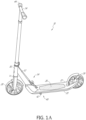
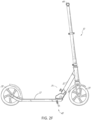
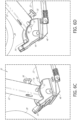
- FIGS 1A and 1B show a scooter 10 having certain features, aspects and advantages of the present disclosure.
- the scooter 10 can include a scooter body 20.
- the scooter body 20 can include a deck 22 and a handlebar assembly 24.
- the deck 22 can include an upper surface 22.
- the upper surface of the deck 22 can include a foot rest surface 26.
- the foot rest surface 26 can support at least one foot or two feet of a user.
- the foot rest surface 26 can support the user when the user is standing.
- the footrest surface 26 can include a gripping region. In some embodiments, the gripping region can help to inhibit or prevent slipping of the user's foot or feet.
- the scooter 10 can include at least one front wheel 28 and/or at least one rear wheel 29.
- the at least one front wheel 28 and/or the at least one rear wheel 29 can be supported by the scooter body 20.
- the front wheel 28 and/or the rear wheel 29 can be spaced apart from one another with the deck 22 extending therebetween.
- the rear wheel 29 can be connected to the deck 22. As shown, at least a portion of the rear wheel 29 can extend within at least a portion of the deck 22.
- a rear end of the deck 22 is connected with an axle of the rear wheel 29.
- the rear end of the deck 22 is tapered.
- the rear end of the deck 22 is narrower than a front end of the deck 22. In some embodiments, the rear end of the deck 22 extends upwardly towards a center of the rear wheel 29. In such configurations, the foot rest surface 26 can be positioned below the rear wheel axle. In some embodiments, the rear wheel 29 can include a rear wheel guard. The rear wheel guard can protect the rear wheel 29 from bumps, rocks, and/or dirt, among other materials.
- the wheels 28, 29 can be generally aligned in the same plane when the wheels 28, 29 are in a neutral position (e.g., Figures 1 and 2B ). In some embodiments, the wheels 28, 29 are in the neutral position when the wheels 28, 29 face in generally the same direction. In some embodiments, the wheels 28, 29 are biased to the neutral position. In some embodiments, the rear wheel 29 is fixed and/or can rotate about an axis other than the rolling axis. In some embodiments, the front wheel 28 is fixed and/or can rotate about an axis other than the rolling axis. In some embodiments, the wheels 28, 29 can be located at opposite ends of the deck 22 (e.g., near fore and/or aft regions of the scooter 10). In some embodiments, the wheels 28, 29 can include plastic, metal, and/or rubber, among other materials.
- the scooter 10 can include a head tube 30.
- the head tube 30 can rotatably support the handlebar assembly 24.
- the handlebar assembly 24 can rotate within the head tube 30 and/or the head tube 30 can rotate about the steering assembly 24. Further details related to the rotatable connection between the head tube 30 and the handlebar assembly 24, among other aspects of the head tube 30 are described in U.S. Application No. 15/409,488 filed on January 18, 2017 and U.S. Patent No. 8,870,200 .
- the front wheel 28 can be operatively coupled to the handlebar assembly 24 so that a user can steer the front wheel 28 by moving the handlebar assembly 24.
- the handlebar assembly 24 can be connected to the front wheel 28 by a steering assembly having a front fork 25.
- the front fork 25 can extend over at least a portion of the front wheel 28.
- the front fork 25 connects to an axle of the front wheel 28.
- the front fork 25 can surround a front wheel guard.
- the front wheel guard can surround at least a portion of the front wheel 28.
- the front wheel guard can protect the front wheel 28 from bumps, rocks, and/or dirt, among other materials.
- a height of the handlebar assembly 24 can be adjusted by sliding one or more telescoping portions of the handlebar assembly 24 relative to one another in a direction toward or away from the deck 22.
- the scooter body 20 can include a support assembly 32.
- the support assembly 32 can connect the head tube 30 to the deck 20.
- the support assembly 32 can extend between the head tube 30 and the deck 22.
- the support assembly 32 can be positioned between the head tube 30 and the deck 22.
- the scooter 10 can include a pivot assembly 34.
- the pivot assembly 34 can allow the support assembly 32 and/or the head tube 30 to rotate with respect to the scooter body 20. As shown, the pivot assembly 34 can be located at the support assembly 32. In certain variants, the pivot assembly 34 can be positioned at the head tube 30 and/or the handlebar assembly 24.
- the scooter 10 can include a support element 40, also referred to herein as a center stand 40.
- the center stand 40 can be mounted to the scooter body 20.
- the center stand 40 can be mounted to a lower side of the foot rest surface 26 (e.g., underneath the foot rest surface 26).
- the center stand 40 can include an ear portion 42. The ear portion 42 can extend laterally beyond the deck 22.
- the scooter 10 can include a hand grip 44, as described in more detail below.
- the hand grip 44 can be disposed on either end of the handlebar assembly 24.
- the hand grip 44 can be ergonomically shaped, such as being generally triangular in shape, among other shapes.
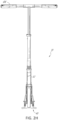
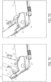
- FIGS 2A-2J illustrate another embodiment of the scooter 10.
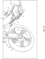
- Figures 2B and 2C illustrate a non-limiting, illustrative embodiment of the pivot assembly 34.
- the pivot assembly 34 can be used with any of the embodiments of the scooters 10 described and/or shown herein.
- the pivot assembly can allow any of the scooters 10 described and/or shown herein to fold and/or unfold.
- the pivot assembly 34 can include a bracket 44.
- the bracket 44 can be mounted onto the deck 22 of the scooter body 20.
- a rod 46 can pass through at least a portion of the bracket 44 and/or through at least a portion of the support assembly 32.
- the support assembly 32 can rotate about the rod 46.
- the rod 46 and the bracket 44 can create a pivot about which the support assembly 32 can rotate relative to the deck 22.
- the support assembly 32 can have a front face 48 that faces in a generally forward direction (e.g., towards the front wheel 28 of the scooter 10).
- the bracket 44 can have a brace portion 50 that extends across the front face 48 of the support assembly 32 and/or supports the front face 48, such as when the support assembly 32 can be in the unfolded configuration.
- the direction of rotation which brings the support assembly 32 toward the brace 50 will be referred to as the "fore" rotational direction.
- the direction of rotation which brings the support assembly 32 away from the brace 50 will be referred to as the "aft" rotational direction.
- the brace portion 50 can limit the amount of fore rotation of the support assembly 32.
- the brace portion 50 can support the support assembly 32 when the scooter 10 is in the unfolded (e.g., riding) configuration.
- the brace 50 can include an upper portion and a lower portion.
- the upper portion can extend outwardly in the fore direction a greater distance than the lower portion of the brace 50.
- the upper portion can extend outwardly in the fore direction the same distance as the lower portion.
- upper and/or the lower portions can sit flush against one another and/or form a generally flat surface.
- a ledge of the brace 50 is approximately aligned with an axis of rotation of the front wheel.
- a ledge of the brace 50 is positioned approximately below a top of the front wheel.
- a ledge of the brace 50 is positioned approximately above the axis of rotation of the front wheel.
- the pivot assembly 34 can include a pin 52.
- the pin 52 can extend from the support assembly 32 and into a fore slot 54 of the bracket 44. In some embodiments, the pin 52 can extend between the support assembly 32 and the fore slot 54. In some embodiments, the pin 52 can generally prevent the support assembly 32 from rotating toward and/or away from the deck 22 when the pin 52 is seated in the fore slot 54. In some embodiments, the pin 52 can generally prevent the support assembly 32 from rotating toward and/or away from the deck 22 by more than 1 to 2 degrees, 2 to 3 degrees, 3 to 4 degrees, 4 to 5 degrees, 5 to 6 degrees, 6 to 7 degrees, 7 to 8 degrees, 8 to 9 degrees, 9 to 10 degrees, degrees between the aforementioned rotation degrees, or other degrees.
- the pivot assembly 34 can include a knob 56.
- the knob 56 can be adapted to move the pin 52.
- the knob 56 can slide the pin 52 along the support assembly 32 radially away from the rod 46.
- Such configurations can free the pin 52 from the fore slot 54 of the bracket 44.
- the support assembly 32 can rotate about the rod 46.
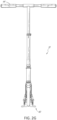
- Figure 3 depicts an embodiment of the scooter 10 in a folded configuration.
- the bracket 44 can include a side face 58.
- the side face 58 can be solid (e.g., Figure 1 ).
- the side face 58 can be generally transparent (e.g., Figure 3 ).
- the pin 52 can be positioned in at least a portion of or all of an aft slot 60 of the bracket 44 when the scooter 10 is in the folded configuration.
- the pin 52 can generally prevent the support assembly 32 from rotating toward and/or away from the deck 22 when the pin 52 is seated in the aft slot 60.
- the pin 52 can generally prevent the support assembly 32 from rotating toward and/or away from the deck 22 by more than 1 to 2 degrees, 2 to 3 degrees, 3 to 4 degrees, 4 to 5 degrees, 5 to 6 degrees, 6 to 7 degrees, 7 to 8 degrees, 8 to 9 degrees, 9 to 10 degrees, degrees between the aforementioned rotation degrees, or other degrees.
- the fore slot 54 and the aft slot 60 can be spaced apart along a length of the side face 58. In some embodiments, the fore slot 54 and the aft slot 60 can be spaced apart by a circumference of an upper edge of the side face 58.
- the pivot assembly 34 can include a spring or other biasing member that biases the pin 52 toward the rod 46 and/or a lower or central portion of the pivot assembly 34.
- the pin 52 can move between the fore and aft slots 54, 60 by sliding along a rail 74.
- the biasing member can apply a force to the pin 52 to hold the pin 52 against the rail 74 so that when the pin 52 is positioned within at least a portion of the fore or aft slot 54, 60 the pin 52 automatically is positioned within the slot 54, 60.
- the pin 52 can remain seated within the slot 54, 60 until a force (such as a force away from the rod 46) is applied to draw the pin 52 radially away from the rod 46.
- Figure 4 shows an embodiment of the pivot assembly 34 with the surrounding portions of the scooter 10 removed for the sake of clarity.
- the pin 52 is coupled to a collar 66.
- the collar 66 can be disposed between two lateral portions 68a,b of the bracket 44.
- the lateral portions 68a,b are generally identically shaped or sized and/or have different shapes or sizes.
- the pin 52 can extend from either side of the collar 66.
- the pin is seated in a fore slot 54 of at least one or both of the lateral portions 68a,b.
- the bracket 44 can have only one lateral portion 68. In such configurations, the pin 52 can extend from only one side of the collar 66 and/or the pin 52 can be seated in the corresponding fore slot 54..
- the knob 56 can be attached to a threaded core 62.
- the threaded core 62 can pass through the collar 66.
- the threaded core 62 can include a foot 64 that can rest on the brace portion 50 of the bracket 44.
- a first rotational direction e.g., clockwise
- the foot 64 moves away from the collar 66 and/or toward the brace portion 50.
- turning the knob 56 in a second rotational direction e.g., counter-clockwise
- the extension and/or retraction of the foot 64 relative to the collar 66 and/or the brace portion 50 can be achieved by various configurations of the pivot assembly 34.
- the threaded core 62 can be coupled with the knob 56 and/or with the foot 64. In some configurations, rotation of the knob 56 can result in rotation of the threaded core 62 and/or the foot 64.
- the knob 56, the threaded core 62, and/or the foot 64 can be coupled together and/or can rotate together as a unit.
- the collar 66 can have an internal thread. The internal thread can mate with an external thread of the threaded core 62. In some configurations, rotation of the knob 56 in the first rotational direction advances the knob 56 along the internal thread of the collar 66. Such configurations can move the knob 56 toward the collar 66 and/or push the foot 64 against the brace portion 50.
- Figure 5 is a side cross-sectional view of an embodiment of the pivot assembly 34.
- the foot 64 can include an external thread 76.
- the external thread 76 can mate with an internal thread 78 of a base portion 80 of the threaded core 62.
- a surface of the foot 64 that faces the brace portion 50 can have a recess 82 (e.g., Figure 7C ).
- the recess 82 can receive an anti-rotation protrusion 84.
- the anti-rotation protrusion 84 can extend from the brace portion 50.
- the recess 82 can have a hexagonal shape.
- the recess 82 can be shaped to receive a protrusion, such as a hexagonal-shaped protrusion (not shown) that extends from the base portion 50.
- the protrusion 84 can be fixed so that the protrusion 84 can be inhibited from rotating with respect to the longitudinal axis of the protrusion 84. Once the protrusion 84 is seated in the recess 82, the protrusion 84 can inhibit or prevent the foot 64 from rotating about the longitudinal axis of the foot 64.
- the core 62 can include a plurality of ridges and/or grooves.
- the collar 66 can include a plurality of ridges and/or grooves.
- the plurality of ridges and/or grooves of the core 62 and the ridges and/or grooves of the collar 66 can intermesh.
- the intermeshing ridges and grooves can allow the core 62 to rotate within the collar 66 and/or prevent the core 62 from moving longitudinally relative to the collar 66.
- the intermeshing ridges and grooves can circumferentially surround the longitudinal axis of the core 62 while maintaining a set longitudinal position.
- the ridges can include a plurality of protrusions that are isolated from one another by a groove positioned between adjacent ridges. In some embodiments, the ridges do not form a continuous protrusion that forms a helical thread.
- the knob 56 can be fixed to and/or be integrally formed with the core 62.
- the core 62 can rotate with the knob 56.
- the pin 52 can be seated in the fore slot 54, and/or the protrusion 84 can be seated in the recess 82.
- the knob 56 can cause the core 62 to rotate in the first rotational direction, such as when the knob 56 is fixed to the core 62.
- the core 62 can rotate around the foot 64.
- the foot 64 can be generally prevented from rotating with the core 62, for example, since the protrusion 84 can be seated in the recess 82.
- the internal thread 78 of the core 62 rotates relative to the external thread 76 of the foot 64. Some configurations can push the foot 64 away from the collar 66.
- the support assembly 32 can be hollow.
- the support assembly 32 can receive the collar 66.
- the collar 66 can include a top surface 70.
- the top surface 70 of the collar 66 can slide along an inner surface 72 of the support assembly 32.
- the surface 70 can include a slot in which the core 62 slides. The slot can extend in a direction that is generally parallel with the longitudinal axis of the support assembly 32.
- the foot 64 when the knob 56 is turned in the first rotational direction to push the foot 64 away from the collar 66, the foot 64 can press against the brace portion 50 and/or push the top surface 70 of the collar 66 against the inner surface 72 of the support assembly 32. In some embodiments, pressing at least a portion of the collar 66 against at least a portion of the support assembly 32 can create a frictional force. In various embodiments, turning the knob 56 in the first rotational direction can secure the pivot assembly 34. In certain confirmations, the pivot assembly 34 does not appreciably rattle or wobble when the scooter 10 is in use. The frictional forces between the collar 66 and the support assembly 32 can reduce the rattle and wobble of the pivot assembly 34.
- the collar 66 can ride inside a track that can be mounted to the support assembly 32. In some embodiments, turning the knob 56 in the first rotational direction can push the collar 66 against a flange of the track. Some configurations can secure the pivot assembly 34 and/or reduce rattling and wobbling of the pivot assembly 34.
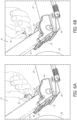
- Figures 6A-6D show a method of folding the scooter 10.
- Figure 6A illustrates a portion of the scooter 10 in an unfolded configuration.
- the pin 52 can be seated in (e.g., fully within) the fore slot 54 of the bracket 44.
- the user can turn the knob 56 in the second rotational direction. Turning the knob 56 can relieve the compression force between the foot 64 and the brace portion 50.
- the user can slide the knob 56 along the support assembly 32 to draw the pin 52 radially away from the rod 46 until at least a portion of the pin 52 exits the fore slot 54 of the bracket 44.
- Figure 6C shows the pin 52 drawn entirely out of the slot 54 and the support assembly 32 rotated at least partially toward the deck 22 of the scooter 10.
- the pin 52 can be positioned between the slots 54, 60. In some embodiments, the pin 52 can be positioned between the slots 54, 60 when the support assembly 32 is rotated toward the deck 22. As the scooter 10 is folded and/or the support assembly 32 is rotated toward the deck 22, the pin 52 can slide along the rail 74 as the pin 52 moves away from the fore slot 52 and toward the aft slot 54.
- Figure 6D shows the scooter in a folded configuration.
- the pin 52 can be seated (e.g., fully within) within the aft slot 60. In this position, the biasing member (not shown) can push the pin 52 radially toward the rod 46 to seat the pin 52 in the aft slot 60 and/or retain the pin 52 within the slot 60.
- the support assembly 32 can be generally fully secured relative to the deck 22 when the pin 52 is fully seated in the aft slot 60.
- Figures 7A-7F show a method of unfolding the scooter 10.
- Figure 7A shows the support assembly 32 and the deck 22 of the scooter 10 in the folded configuration.
- the pin 52 is seated in (e.g., fully within) the aft slot 60 of the bracket 44.
- Figure 7B depicts a user sliding the knob 56 along the support assembly 32 to bring the pin 52 out of the aft slot 60.
- Figure 7C shows the pin 52 slides along the rail 74 from the aft slot 60 toward the fore slot 54 as the support assembly 32 is rotated toward the brace portion 50 of the bracket 44.
- Figure 7D shows the pin 52 fully seated within the fore slot 54.
- the biasing member (not shown) can push the pin 52 radially toward the rod 46 to seat the pin 52 in the fore slot 54.
- Figure 7E shows a user turning the knob 56 in the second rotational direction to push the foot 64 against the brace portion 50 of the bracket 44.
- Such configurations can create a compressive force that reduces and/or eliminates rattling and/or wobbling of the pivot assembly 34 when the scooter 10 is used.
- Figure 7F depicts the scooter 10 in the unfolded configuration. As shown, the knob 56 has been advanced sufficiently in the second rotational direction to reduce or eliminate rattling and/or wobbling of the pivot assembly 34 when the scooter 10 is used, as described herein.
- the pin 52 can be seated in the fore slot 54 of the bracket 44 so that the support assembly 32 can be generally fully secured relative to the deck 22 when the pin 52 is fully seated in the fore slot 54.
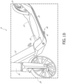
- FIG. 1A and 1B illustrate an embodiment of the scooter 10.
- the scooter 10 can include the center stand 40.
- Figure 1B shows an embodiment of the center stand 40 when the center stand 40 is in the retracted position.
- the center stand 40 can be mounted underneath the deck 22.
- the center stand 40 can move between a retracted and/or a deployed position. In the retracted position, the center stand 40 can be positioned substantially parallel to a top surface of the deck 22. In the deployed position, the center stand 40 can form an angle with the deck 22 and/or may not be generally parallel to the deck 22.
- the scooter 10 can roll without the center stand 40 contacting a riding surface upon which the scooter rolls.
- a portion of the center stand 40 may contact the riding surface.
- Such configurations can allow the center stand 40 to hold the scooter 10 in an upright position while the scooter 10 is stationary.
- the center stand 40 can have an ear portion 42.
- the ear portion 42 can extend laterally away from one or both lateral sides of the scooter body 20. In some embodiments, a portion of the ear portion 42 that extends from the near side of the scooter body 20 is visible, while the ear portion 42 that extends from the far side of the scooter body 20 cannot be seen from this view.
- the ear portion 42 can be sized and positioned so that a user can push by foot the ear portion 42 from the retracted position to the deployed position. In some embodiments, the ear portion 42 can be positioned below the deck 22. In some embodiments, the ear portion 42 can be positioned immediately adjacent to the scooter body 20.
- the ear portion 42 can form a tubular structure with a generally U-shape, among other shapes.
- the ear portion 42 can form a ledge that can be disposed lower than (e.g., closer to the ground than) the scooter body 20.
- the top of the ear portion 42 can be generally parallel to the deck 22 of the scooter 10.
- the ear portion 42 can be positioned slightly closer to the front wheel 28 than to the rear wheel 29.
- the ear portion 42 can be a single bar, can be spaced apart from the scooter body 20, and/or can be positioned closer to the rear wheel 29 than to the front wheel 28.
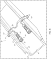
- Figure 8 is a bottom view of a portion of the scooter body 20 showing an embodiment of the center stand 40 in the retracted position.
- the embodiments of the center stand 40 described and/or shown herein can be used with any of the scooters 10 described and/or shown herein.
- the scooter body 20 can include a recessed central portion 86.
- the central portion 86 can be disposed between a pair of sidewalls 88.
- the center stand 40 can be attached to the central portion 86 of the scooter body 20 by at least one or two mount assemblies 90.
- the mount assemblies 90 can be spring-loaded. The mount assemblies can draw the center stand 40 toward the central portion 86 once a collar 92 of the spring 94 passes over an inflection point on a cam surface 96 of a mounting bracket 98.
- the inflection point is positioned at a general center of the cam surface 96, and/or closer to one or more of the ends of the cam surface 96.
- the center stand 40 can be attached to the scooter body 20 by a single mount assembly 90.
- the mount assembly 90 can be attached to the sidewall 88 of the scooter body 20 and/or not attached to the central portion 86 of the scooter body 20. In some embodiments, in the retracted position, the mount assembly 90 and at least a portion of the center stand 40 can be recessed in (e.g., received in and/or not protruding from) the recessed central portion 86.
- the center stand 40 can have a base portion 100.
- the base portion 100 can extend across the central portion 86 of the scooter body 20.
- the base portion 100 can be positioned substantially perpendicular to sidewalls 88 of the scooter body 20.
- the ear portions 42 can be disposed at the lateral extent of the base portion 100. (e.g., Figure 8 ).
- the base portion 100 can have an arm portion 102 that wraps around at least a portion of the sidewall 88 of the scooter body 88.
- the arm portion 102 can position the ear portion 42 toward the deck 22 of the scooter body 88.
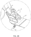
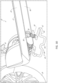
- Figure 9 is a perspective view of the center stand 40 in the deployed position.
- the base portion 100 of the center stand 40 can be in contact with the riding surface.
- the front wheel 28 can be elevated off of the riding surface.
- the center stand 40 can be positioned so that the arm portions 102 angle toward the rear of the scooter as the arm portions 102 extend in the lateral direction.
- the base portion 100 can have a bent footprint that provides stability to the center stand 40 when the center stand 40 can be in the deployed position.
- the bent footprint of the center stand 40 can include a central portion 104.
- the central portion 104 can be substantially perpendicular to the side wall 88 of the scooter body 20.
- the central portion 104 can be disposed between at least two arm portions 102 that are angled away from the front of the scooter 10.
- the center stand 40 can be automatically drawn into the retracted position as a user propels the scooter forward.
- a user can place one foot on the deck 22 of the scooter 10 and propel the scooter 10 forward by pushing off from the ground with the other foot. Movement of the scooter 10 can cause the center stand 40 to rotate from the deployed position to the retraced position.
- the collar 92 of the spring 94 of the mounting assembly 90 can slide along the cam surface 96 of the mounting bracket 98. Once the collar 92 of the spring passes the inflection point 106 of the mounting bracket 98, the spring 94 can pull the center stand 40 against the side wall 88 of the scooter body 20. Such configurations can bring the center stand 40 into the fully retracted position.
- the center stand 40 can be retracted by propelling the scooter 10 forward and may not require that the center stand 40 be retracted before the scooter 10 moves.
- Figures 10-12 illustrate other embodiments of the center stand 40 that can include many of the same or identical features as described above.
- Figure 10 depicts another embodiment of the center stand 40.
- the base portion 100 of the center stand 40 can produce a different footprint for the center stand 40.
- the base portion 100 can adjust the placement of the ear portions 42 when the center stand 40 is in retracted and/or deployed position.
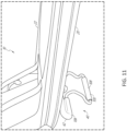
- Figure 11 illustrates an embodiment of the center stand 40.
- the ear portions 42 can contact the scooter body 20 when the center stand 40 is in the deployed position.
- Some configurations can add stability to the scooter 10 when the scooter 10 is stationary by allowing the scooter to lean on at least the ear portion 42.
- the center stand 40 can include cushioning features, such as foam portions 108.
- the foam portions 108 can be positioned on the ear portion 42 and/or on the base portion 100.
- the foam portions 108 can enhance the stability of the scooter 10 when the scooter 10 is resting on the center stand 40.
- the foam portions 108 can enhance friction between the center stand 40 and the riding surface. The enhanced friction can increase the stability of the scooter 10.
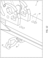
- Figure 12 illustrates that the center stand 40 can be mounted to the scooter body 20 using through holes 110 that are disposed on the deck 22 of the scooter body 20.
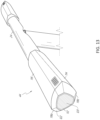
- FIG 13 illustrates an embodiment of the handgrip 44.
- the embodiments of the handgrip 44 described and/or shown herein can be used with any of the scooters 10 described and/or shown herein.
- the scooter 10 can include a handgrip 44 mounted on one or both ends of the handlebar assembly 24.
- the handgrip 44 can include a substantially triangular shape, among others.
- the handgrip 44 can include a front surface 112, a rear surface 114, and/or a top surface 116, among others.
- a front surface 112 of the handgrip 44 can face toward the front wheel 28 of the scooter 10.
- the front surface 112 can be angled toward the ground at an angle of approximately 45°, as shown in Figure 13 .
- the handgrip 44 can include a rear surface 114 that faces toward the rear wheel 29 of the scooter 10.
- the rear surface 114 can be angled toward the ground at an angle of approximately 45°.
- the top surface 116 can be substantially parallel with the ground.
- the front, rear, and top surfaces 112, 114, 116 can be slightly convex. Some configurations can improve comfort of the handgrip 44.
- the handgrip 44 can include intervening surfaces 118a,b,c.
- the intervening surfaces 118a, b, c can be disposed between the front, rear, and top surfaces 112, 114, 116.
- the handgrip 44 can include a cap surface 120.
- the cap surface 120 can be substantially transverse to the front, rear, and top surfaces 112, 114, 116.
- the handgrip 44 can have facet surfaces 122.
- the facet surfaces 122 can connect the cap surface 120 to the other surfaces of the handgrip 44, as shown in at least Figure 13 .
- the handgrip 44 can be adapted and/or oriented to enhance user comfort and/or control of the scooter 10.
- the top surface 116 and/or the intervening surface 118b can provide a slightly convex planar surface that supports the palm of the user.
- the front surface 112 and/or the intervening surface 118a can provide a comfortable radius of curvature for the fingers of the user to wrap around the handgrip 44.
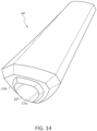
- Figure 14 illustrates another embodiment of the handgrip 44 that can include a tiered cap surface 120.
- the tiered cap surface 120 can include a first surface 120a, and/or a second surface 120b.
- the second surface 120b can be positioned inwardly from a central region of the handgrip 44.
- the first surface 120a can be positioned inwardly from the second surface 120b.
- the terms “approximately,” “about,” and “substantially” as used herein represent an amount close to the stated amount that still performs a desired function or achieves a desired result.
- the terms “approximately”, “about”, and “substantially” may refer to an amount that is within less than or equal to 10% of the stated amount.
- the term “generally” as used herein represents a value, amount, or characteristic that predominantly can include or tends toward a particular value, amount, or characteristic.
- the term “generally parallel” can refer to something that departs from exactly parallel by less than or equal to 15°.
- the term "generally perpendicular” can mean something that departs from exactly, perpendicular by less than or equal to 15°.
- the term “generally aligned” can mean something that departs from exactly, aligned by less than or equal to 15°.
- a device configured to are intended to include one or more recited devices. Such one or more recited devices can also be collectively configured to carry out the stated recitations. For example, "a device configured to carry out recitations A, B, and C" can include a first device configured to carry out recitation A working in conjunction with a second device configured to carry out recitations B and C.
Landscapes
- Engineering & Computer Science (AREA)
- Mechanical Engineering (AREA)
- Motorcycle And Bicycle Frame (AREA)
- Steering Devices For Bicycles And Motorcycles (AREA)
Claims (15)
- Trottinette (10) comprenant :un ensemble (24) formant guidon ;une plate-forme (22) ; etun ensemble de pivotement (34) qui relie l'ensemble (24) formant guidon à la plate-forme (22), l'ensemble de pivotement comprenant :un ensemble de support (32) relié de manière pivotante à une fixation (44) par une tige (46), la fixation comprenant une surface de rail présentant une première région de réception espacée d'une seconde région de réception, une portion intermédiaire de la surface de rail étant disposée entre les première et seconde régions de réception, la portion intermédiaire étant disposée à une première distance par rapport à la tige, la première distance étant supérieure à une distance entre la tige et la première ou seconde région de réception ;un bouton (56) relié à une goupille (52) par un collier (66), le bouton étant configuré pour faire coulisser la goupille radialement en éloignement de la tige ;une portion de renfort (50) s'étendant à travers une face de l'ensemble de support (32) ; etun arbre (62) passant à travers le collier (66), une première extrémité de l'arbre étant fixée au bouton (56), une seconde extrémité de l'arbre étant opposée à la première extrémité,caractérisée en ce quele bouton est configuré de telle sorte que la rotation du bouton dans une première direction de rotation déplace la seconde extrémité en engagement avec la portion de renfort (50), empêchant ainsi tout déplacement de l'ensemble (24) formant guidon par rapport à la plate-forme (22).
- Trottinette selon la revendication 1, dans laquelle le bouton (56) avance longitudinalement vers l'ensemble de support (32) lorsque le bouton est tourné dans la première direction de rotation.
- Trottinette selon la revendication 1, dans laquelle le bouton (56) reste fixe longitudinalement par rapport à l'ensemble de support (32) lorsque le bouton est tourné dans la première direction de rotation.
- Trottinette selon la revendication 1, comprenant en outre un pied (64) disposé entre la seconde extrémité de l'arbre et la portion de renfort (50).
- Trottinette selon la revendication 4, dans laquelle l'un parmi le pied (64) et la portion de renfort (50) comprend une saillie, dans laquelle l'autre parmi le pied et la portion de renfort comprend un évidement, la saillie étant configurée pour s'ajuster à l'intérieur de l'évidement et empêcher toute rotation du pied par rapport à un axe longitudinal de l'arbre.
- Trottinette selon la revendication 1, dans laquelle la fixation (44) comprend une première portion latérale (68a) et une seconde portion latérale (68a), l'ensemble de support (32) étant disposé entre les première et seconde portions latérales.
- Trottinette selon la revendication 6, dans laquelle la première région de réception comprend une première région de réception antérieure et une première région de réception postérieure, la première région de réception antérieure étant disposée sur la première portion latérale (68a), la première région de réception postérieure étant disposée sur la seconde portion latérale (68b).
- Trottinette selon la revendication 7, dans laquelle la seconde région de réception comprend une seconde région de réception antérieure et une seconde région de réception antérieure postérieure, la seconde région de réception antérieure étant disposée sur la première portion latérale (68a), la seconde région de réception antérieure postérieure étant disposée sur la seconde portion latérale (68b).
- Trottinette selon la revendication 8, dans laquelle la goupille (52) comprend une portion antérieure et une portion postérieure, la portion antérieure de la goupille étant configurée pour venir en contact avec au moins une portion de la première portion latérale, la portion postérieure de la goupille étant configurée pour venir en contact avec au moins une portion de la seconde portion latérale.
- Trottinette selon la revendication 1, comprenant en outre un support rétractable, le support comprenant :un ensemble de montage (90) fixé à la plate-forme de la trottinette ;une portion de base (100) fixée de manière pivotante à l'ensemble de montage, la portion de base étant sensiblement perpendiculaire à un axe longitudinal de la trottinette ;une première portion d'oreille (42) couplée à la portion de base et s'étendant latéralement au-delà d'un premier côté de la plate-forme ; etune seconde portion d'oreille (42) couplée à la portion de base et s'étendant latéralement au-delà d'un second côté de la plate-forme, le second côté étant opposé au premier côté,dans laquelle l'ensemble de montage est de préférence configuré pour déplacer la portion de base entre une position rétractée et une position déployée, la position rétractée étant de préférence une position dans laquelle la portion d'oreille est plus éloignée du sol que ne l'est au moins une portion de la portion de base, oudans laquelle l'ensemble de montage est plus éloigné du sol que ne l'est au moins une portion de la portion de base,dans laquelle, de préférence, une roue avant de la trottinette sur laquelle le support rétractable est monté est soulevée du sol lorsque le support rétractable est dans la position déployée.
- Trottinette selon la revendication 10, comprenant en outre une propriété d'amortissement (108) disposée soit sur au moins une portion de la portion d'oreille, soit sur au moins une portion de la portion de base.
- Trottinette selon la revendication 1, dans laquelle l'ensemble de guidon comprend une poignée ergonomique (44), la poignée ergonomique comprenant :une surface avant (112) couplée à une surface supérieure (116) par une première surface intermédiaire ; etune surface arrière (114) couplée à la surface supérieure par une seconde surface intermédiaire, dans laquelle la surface supérieure est convexe, et dans laquelle la seconde surface intermédiaire est sensiblement parallèle à la surface avant,dans laquelle la poignée présente de préférence une forme sensiblement triangulaire lorsqu'on regarde le long d'un axe longitudinal de la poignée,dans laquelle, en utilisation, un sommet de la forme sensiblement triangulaire est de préférence plus proche du sol que ne l'est toute autre portion de la forme sensiblement triangulaire, etdans laquelle, en utilisation, un côté de la forme sensiblement triangulaire est de préférence plus éloigné du sol que ne l'est toute autre portion de la forme sensiblement triangulaire.
- Procédé destiné à empêcher un cliquetis d'un ensemble (24) formant guidon de la trottinette selon l'une des revendications précédentes par rapport à la plate-forme (22) de la trottinette, le procédé comprenant :placer la goupille (52) à l'intérieur d'une fente avant de la fixation (44) ;tourner le bouton (56) dans une première direction de rotation,dans lequel le bouton est relié à la goupille par le collier (92) et relié à la première extrémité de l'arbre (62) ; etdéplacer la seconde extrémité de l'arbre opposée à la première extrémité en engagement avec la portion de renfort (50) en réponse à la rotation du bouton dans la première direction de rotation, créant ainsi une force de compression qui empêche tout cliquetis de l'ensemble de guidon de la trottinette par rapport à la plate-forme de la trottinette lorsque la trottinette est utilisée.
- Procédé selon la revendication 13, comprenant en outre soit :faire coulisser la goupille le long d'une surface de rail de la fixation depuis une fente arrière vers la fente avant ; soitfaire avancer le bouton longitudinalement.
- Procédé selon la revendication 13, comprenant en outre le fait d'insérer une saillie dans un évidement, empêchant ainsi toute rotation d'un pied (64) par rapport à un axe longitudinal de l'arbre, dans laquelle l'un parmi le pied et la portion de renfort comprend la saillie et l'autre parmi le pied et la portion de renfort comprend l'évidement, le pied étant disposé entre la seconde extrémité de l'arbre et la portion de renfort.
Applications Claiming Priority (2)
| Application Number | Priority Date | Filing Date | Title |
|---|---|---|---|
| US201662383273P | 2016-09-02 | 2016-09-02 | |
| PCT/US2017/049706 WO2018045218A1 (fr) | 2016-09-02 | 2017-08-31 | Trottinette pliante anti-cliquetis |
Publications (3)
| Publication Number | Publication Date |
|---|---|
| EP3507177A1 EP3507177A1 (fr) | 2019-07-10 |
| EP3507177A4 EP3507177A4 (fr) | 2020-08-26 |
| EP3507177B1 true EP3507177B1 (fr) | 2023-11-29 |
Family
ID=61282293
Family Applications (1)
| Application Number | Title | Priority Date | Filing Date |
|---|---|---|---|
| EP17847577.8A Active EP3507177B1 (fr) | 2016-09-02 | 2017-08-31 | Trottinette pliante anti-cliquetis |
Country Status (5)
| Country | Link |
|---|---|
| US (3) | US10526034B2 (fr) |
| EP (1) | EP3507177B1 (fr) |
| JP (1) | JP7039567B2 (fr) |
| CN (5) | CN207875890U (fr) |
| WO (1) | WO2018045218A1 (fr) |
Families Citing this family (8)
| Publication number | Priority date | Publication date | Assignee | Title |
|---|---|---|---|---|
| CN208085899U (zh) * | 2016-06-15 | 2018-11-13 | 快乐活运动有限公司 | 车辆和用于车辆的枢转接头 |
| CN207875890U (zh) * | 2016-09-02 | 2018-09-18 | 美国锐哲有限公司 | 一种符合人体工程学的把手 |
| USD815215S1 (en) | 2016-09-08 | 2018-04-10 | Razor Usa Llc | Scooter |
| CN107651081B (zh) * | 2017-11-08 | 2024-01-19 | 兰溪普泰工贸有限公司 | 滑板车及折叠机构和其折叠、锁紧方法 |
| JP7534289B2 (ja) * | 2018-09-28 | 2024-08-14 | レイザー・ユーエスエー・エルエルシー | ステアリングロックを伴うスクータ |
| USD883395S1 (en) * | 2018-11-29 | 2020-05-05 | Shenzhen Leqi Intelligent Technology Co., Ltd. | Scooter |
| USD919011S1 (en) * | 2019-10-08 | 2021-05-11 | Hongji Intelligent Bike Co., Ltd | Scooter wheel |
| TWI775564B (zh) * | 2021-08-12 | 2022-08-21 | 張旺連 | 滑板車之前叉摺疊機構 |
Family Cites Families (191)
| Publication number | Priority date | Publication date | Assignee | Title |
|---|---|---|---|---|
| US606525A (en) | 1898-06-28 | And kenneth | ||
| US640906A (en) * | 1899-03-06 | 1900-01-09 | William H Hart Jr | Bicycle-support. |
| US644074A (en) * | 1899-03-06 | 1900-02-27 | William H Hart Jr | Bicycle-support. |
| US634298A (en) * | 1899-03-06 | 1899-10-03 | William H Hart Jr | Bicycle-support. |
| US628433A (en) | 1899-03-23 | 1899-07-04 | Stanley W Finch | Skate. |
| US640614A (en) * | 1899-06-01 | 1900-01-02 | John Booth | Bicycle-support. |
| US730622A (en) | 1903-02-02 | 1903-06-09 | Milton Le Roy Edmunds | Bicycle-balance. |
| FR396141A (fr) | 1908-01-17 | 1909-04-02 | Gaston Burghardt | Appareil de locomotion auxiliaire |
| US1279966A (en) * | 1917-01-15 | 1918-09-24 | William J Baker | Skatemobile. |
| US1297282A (en) | 1918-04-13 | 1919-03-11 | Joseph F White | Child's vehicle. |
| US1345038A (en) | 1918-12-11 | 1920-06-29 | Joseph D Uppling | Roller-skate |
| US1391312A (en) | 1920-08-25 | 1921-09-20 | Edward J Gebhardt | Sled |
| US1534601A (en) | 1924-06-16 | 1925-04-21 | Matveyeff Michael Nickefor | Roller skate |
| US1658068A (en) | 1924-09-15 | 1928-02-07 | White Arthur | Wheeled toy |
| US1570189A (en) | 1924-12-17 | 1926-01-19 | Sturm John Simon | Adjustable shovel |
| US1614822A (en) | 1925-07-20 | 1927-01-18 | Roman B Bukolt | Scooter |
| US1701410A (en) | 1926-08-23 | 1929-02-05 | Hornquist Frank | Child's vehicle |
| US1714000A (en) | 1926-11-09 | 1929-05-21 | Keystone Lantern Company | Scooter brake |
| US1687953A (en) | 1926-12-16 | 1928-10-16 | Obie W Starks | Handle mounting for brushes |
| US1653558A (en) | 1927-01-21 | 1927-12-20 | Frank B Fisher | Bicycle skate |
| US1687739A (en) | 1927-03-19 | 1928-10-16 | Walter A Slusher | Roller skate |
| US1968975A (en) | 1931-04-14 | 1934-08-07 | Upsacker Andrew | Snow scooter |
| US2198667A (en) | 1938-11-23 | 1940-04-30 | Hagenes Magnus | Sport vehicle |
| US2460395A (en) | 1946-04-27 | 1949-02-01 | Northwest Metal Products Inc | Child's scooter |
| US2439556A (en) | 1946-07-17 | 1948-04-13 | Joseph C Bancroft | Scooter |
| US2546711A (en) | 1948-10-19 | 1951-03-27 | Charles G Amendt | Scooter |
| GB699673A (en) * | 1952-01-17 | 1953-11-11 | David Sebel | Improvements in or relating to velocipedes |
| US3006659A (en) | 1960-10-27 | 1961-10-31 | Krasnoff Gilbert | Treadle scooter |
| US3288251A (en) | 1965-05-18 | 1966-11-29 | Sakwa Paul | Skateboard brake |
| US3396928A (en) | 1966-07-15 | 1968-08-13 | Hamilton Cosco Inc | Leg mounting |
| US3484116A (en) | 1968-12-19 | 1969-12-16 | William R Allen | Shuffle skate |
| US6234501B1 (en) | 1970-02-23 | 2001-05-22 | Chih-Liang Chen | Foldable scooter with head tube assembly, brake and suspension |
| US3684305A (en) | 1970-08-17 | 1972-08-15 | Benjamin J Mcdonald | Roller ski apparatus |
| JPS4944845Y2 (fr) * | 1971-10-20 | 1974-12-07 | ||
| JPS4851660A (fr) | 1971-10-29 | 1973-07-20 | ||
| FR2201108B1 (fr) | 1972-09-25 | 1977-12-23 | Copier Henri | |
| US3891225A (en) | 1974-04-22 | 1975-06-24 | Raymond V Sessa | Wheeled ski skate |
| US4033596A (en) | 1975-08-25 | 1977-07-05 | John Peter Andorsen | Roller ski having leg operated braking means |
| US4003582A (en) | 1975-11-13 | 1977-01-18 | Maurer Jeffrey A | Skate board wheel brake assembly |
| CH595859A5 (fr) | 1976-02-17 | 1978-02-28 | Altorfer Metall & App | |
| US4103917A (en) | 1976-10-26 | 1978-08-01 | Woody-Widolf, Inc. | Skateboard truck |
| US4144822A (en) | 1977-01-24 | 1979-03-20 | Roberts Mfg., Inc. | Folding leg mechanism |
| US4088334A (en) | 1977-03-25 | 1978-05-09 | Johnson Elmer E | Skateboard brake |
| US4166629A (en) | 1977-11-21 | 1979-09-04 | List Richard A | Skateboard truck |
| US4179134A (en) | 1978-07-26 | 1979-12-18 | Atkinson Wallace E | Removable trainer handle and brake for skateboard |
| US4202559A (en) | 1978-08-10 | 1980-05-13 | Piazza John Jr | Skateboard |
| US4169687A (en) | 1978-08-11 | 1979-10-02 | Schull George R | Lock for extendable leg assembly |
| SU912584A1 (ru) * | 1980-07-22 | 1982-03-15 | Специализированное Конструкторское Бюро Эскалаторостроения Министерства Тяжелого И Транспортного Машиностроения | Руко тка рул велосипеда |
| US4394029A (en) | 1981-04-03 | 1983-07-19 | Holmgren Frank E | Foot operated vehicle |
| US4377295A (en) * | 1981-06-01 | 1983-03-22 | Lemman Cecil L | Apparatus for uprighting a motorized two-wheeled vehicle |
| US4584735A (en) | 1984-10-09 | 1986-04-29 | Lambro Industries, Inc. | Dustpan with a control handle |
| US4707884A (en) | 1986-06-06 | 1987-11-24 | Chang San T | Foldable handle for a skateboard |
| US4735392A (en) | 1987-01-30 | 1988-04-05 | Lisle Corporation | Collapsible support platform |
| US4790550A (en) | 1987-02-12 | 1988-12-13 | Simpson Paul A | Scooter |
| US4799701A (en) | 1987-07-06 | 1989-01-24 | Lindau Mark S | Scooter |
| US4795181A (en) | 1988-04-04 | 1989-01-03 | Armstrong Robert B | Skateboard |
| JPH0224264A (ja) * | 1988-07-11 | 1990-01-26 | An Kurafuto:Kk | グリップ装置およびそれを用いたハンドル |
| US4905946A (en) | 1989-02-08 | 1990-03-06 | Wang Lai S | Adjustable leg assembly |
| US4969231A (en) * | 1989-05-17 | 1990-11-13 | Easco Hand Tools, Inc. | Hand tool handle having end cap with indicia |
| US5042622A (en) | 1990-05-22 | 1991-08-27 | Leonard Smith | Shopping cart foot brake assembly |
| US5234225A (en) * | 1990-08-13 | 1993-08-10 | Yaple Winfred E | Powered motorcycle lift/stand |
| JPH04112186A (ja) | 1990-08-29 | 1992-04-14 | Kawasaki Steel Corp | 円筒物の端面除塵方法及び端面除塵装置 |
| US5102079A (en) | 1990-11-23 | 1992-04-07 | Lee Jin Ten | Connecting assembly for a tripod |
| JPH04112186U (ja) * | 1991-03-15 | 1992-09-29 | 修 長岡 | 自転車用スタンド |
| US5150762A (en) | 1991-04-26 | 1992-09-29 | Ranger All Season Corp. | Personal mobility vehicle |
| US5183129A (en) | 1991-06-17 | 1993-02-02 | Powell Robert M | Collapsible scooter |
| US5192099A (en) | 1991-08-27 | 1993-03-09 | Riutta Raine R | Roller skate starting and stopping aids |
| US5383536A (en) | 1991-10-29 | 1995-01-24 | Saf-T-Loc, Inc. | Foot actuated wheel brake |
| US5320367A (en) | 1992-04-13 | 1994-06-14 | Landis Robert M | Braking method and apparatus for an in-line roller skate |
| DE4215283A1 (de) * | 1992-05-09 | 1993-11-11 | Karl Adolf Weidt | Zweiradfahrzeug |
| JPH06329069A (ja) * | 1993-05-26 | 1994-11-29 | Sanyo Electric Co Ltd | 電動二輪スケート |
| US5437425A (en) | 1994-02-14 | 1995-08-01 | Hou; Chun H. | Folding stand for an office chair |
| US5501479A (en) * | 1994-11-08 | 1996-03-26 | Fehrenbach; Donald E. | Kickstand bumper |
| WO1997015485A1 (fr) | 1995-10-26 | 1997-05-01 | Fruechtenicht Robert D | Trottinette acrobatique |
| US5630633A (en) | 1996-04-22 | 1997-05-20 | Dupre; Herman K. | Shovel with driven tiltable blade |
| US5692761A (en) | 1996-07-15 | 1997-12-02 | Republic Tool & Mfg. Corp. | Utility cart |
| US5938223A (en) | 1997-01-10 | 1999-08-17 | Brunswick Corporation | Folding trailer gooseneck |
| DE19711042A1 (de) | 1997-03-04 | 1998-09-10 | Clemens Bucher | Kombinierter Personen- und Transportroller |
| US5816614A (en) * | 1997-03-21 | 1998-10-06 | Burke, Inc. | Tiller assembly for personal mobility vehicles |
| US5848660A (en) | 1997-04-16 | 1998-12-15 | Zap Power Systems | Portable collapsible scooter |
| US6120044A (en) | 1997-05-27 | 2000-09-19 | Tsai; Suei Der | Foldable rollerboard |
| US5927733A (en) | 1997-11-21 | 1999-07-27 | Banda; Juan Antonio Heyer | Folding, portable, non motorized two wheel scooter |
| FR2771368B1 (fr) * | 1997-11-26 | 1999-12-24 | Jean Pierre Leroy | Bequille hydraulique pour moto |
| DE29801045U1 (de) | 1998-01-22 | 1998-03-05 | Dofair Company Ltd., Keelung | Zugvorrichtung in einer Gelenkverbindung für eine Klappleiter |
| US6206387B1 (en) | 1998-12-30 | 2001-03-27 | Shui-Te Tsai | Collapsible skateboard |
| JP3072486B2 (ja) | 1999-01-18 | 2000-07-31 | 株式会社シギヤ精機製作所 | 眼鏡用レンズ測定装置と、その測定子 |
| TW399589U (en) | 1999-02-02 | 2000-07-21 | J D Components Co Ltd | Rear wheel brake device of sliding scooter |
| NL1013919C2 (nl) | 1999-12-22 | 2001-06-25 | Robertus Anthonius Maria Van A | Step. |
| TW427279U (en) | 2000-02-03 | 2001-03-21 | Wu Yau Ming | Improved folding structure for scooter |
| US6409190B1 (en) | 2000-02-21 | 2002-06-25 | Shui-Te Tsai | Front suspension device for a skate cart |
| USD435873S1 (en) | 2000-03-27 | 2001-01-02 | Yan-Yee Lee | Slide cart |
| JP3072486U (ja) * | 2000-04-13 | 2000-10-20 | 豐益 田 | 片足用スクータの折り畳み構造 |
| US6270095B1 (en) | 2000-04-25 | 2001-08-07 | Joe Lee | Foldable skate board scooter |
| CN2425680Y (zh) * | 2000-05-15 | 2001-04-04 | 陈定兴 | 一种滑板车的立脚 |
| GB2362362A (en) * | 2000-05-18 | 2001-11-21 | He Cheng Fa Entpr Co Ltd | Foldable scooter |
| GB2362624A (en) * | 2000-05-24 | 2001-11-28 | Far Great Plastics Ind Co Ltd | Side support for a scooter |
| USD435874S1 (en) | 2000-06-09 | 2001-01-02 | He Cheng Fa Enterprise Co., Ltd. | Skatemobile |
| US6179307B1 (en) | 2000-06-13 | 2001-01-30 | Chen Shou Mao | Skateboarding vehicle |
| JP2002000790A (ja) * | 2000-06-19 | 2002-01-08 | Jd Japan:Kk | スケートボード |
| US6182988B1 (en) | 2000-06-19 | 2001-02-06 | Modas Shing Company Ltd. | Folding device for a scooter |
| US6276701B1 (en) * | 2000-06-19 | 2001-08-21 | Ching Chiuan Chen | Scooter having a safety folding mechanism |
| CN2425683Y (zh) * | 2000-06-21 | 2001-04-04 | 久鼎金属实业股份有限公司 | 滑板车的脚架 |
| US6332621B1 (en) | 2000-06-21 | 2001-12-25 | Meng-Liang Wu | Folding structure for a skate board scooter |
| CN2430193Y (zh) * | 2000-06-21 | 2001-05-16 | 久鼎金属实业股份有限公司 | 滑板车的脚架结构 |
| CN2436196Y (zh) * | 2000-07-13 | 2001-06-27 | 信隆车料(深圳)有限公司 | 滑板车停放支架 |
| US6390483B1 (en) * | 2000-07-19 | 2002-05-21 | Hao Yih Trading Co., Ltd. | Folding device for scooter |
| US6378880B1 (en) | 2000-07-31 | 2002-04-30 | Chao Ming Lin | Folding device for a skate board scooter |
| USD446259S1 (en) | 2000-08-18 | 2001-08-07 | Enor Corporation | Scooter with rear wheel brake |
| USD438911S1 (en) | 2000-08-29 | 2001-03-13 | Vic. Chen | Scooter |
| USD439623S1 (en) | 2000-08-30 | 2001-03-27 | Chiaphua Industries Limited | Scooter |
| USD438912S1 (en) | 2000-08-30 | 2001-03-13 | Chiaphua Industries, Limited | Scooter |
| US6273205B1 (en) | 2000-09-13 | 2001-08-14 | Shui-Te Tsai | Power clutch mechanism of scooter |
| US6652941B1 (en) * | 2000-09-27 | 2003-11-25 | Bic Corporation | Grip element and method of manufacture thereof |
| US6298952B1 (en) | 2000-09-29 | 2001-10-09 | Shui-Te Tsai | Brake of rear wheel of scooter |
| USD447187S1 (en) | 2000-10-09 | 2001-08-28 | Ronald H. Powers | Scooter |
| CN2449767Y (zh) * | 2000-10-11 | 2001-09-26 | 久鼎金属实业股份有限公司 | 滑板车的脚架 |
| US20020050696A1 (en) | 2000-10-30 | 2002-05-02 | Mey-Chu Lan | Handlebar unit and footplate mounting arrangement for kick scooter |
| JP3647388B2 (ja) * | 2000-11-08 | 2005-05-11 | 株式会社アトラスオート | 補助電動機付きスケータ |
| USD452284S1 (en) | 2000-11-20 | 2001-12-18 | Mcginnis Kevin J. | Scooter |
| CN2457013Y (zh) * | 2000-12-04 | 2001-10-31 | 陈定兴 | 滑板车折收结构 |
| USD456460S1 (en) | 2000-12-21 | 2002-04-30 | Shih Fan Tseng | Electric scooter |
| US20020084621A1 (en) * | 2001-01-03 | 2002-07-04 | Shui-Te Tsai | Support leg of scooter |
| US6491312B2 (en) * | 2001-01-05 | 2002-12-10 | Timothy C. Reynolds | Scooter steering control |
| US20020093161A1 (en) | 2001-01-12 | 2002-07-18 | Enor Corporation | Scooter |
| US20020093164A1 (en) * | 2001-01-16 | 2002-07-18 | Dean Tai | Skate cart kickstand |
| USD453198S1 (en) | 2001-01-18 | 2002-01-29 | Kash 'n Gold, Ltd. | Non-motorized scooter |
| USD454377S1 (en) | 2001-02-22 | 2002-03-12 | Hao Yih Trading Co., Ltd. | Scooter |
| US6428021B1 (en) * | 2001-03-16 | 2002-08-06 | Ko Chen Tung | Folding and positioning device of scooter |
| US20020140193A1 (en) | 2001-03-27 | 2002-10-03 | Chai Kao Teh | Folding and locking arrangement for collapsible scooter |
| US20020145264A1 (en) | 2001-04-09 | 2002-10-10 | Chin-Lien Hung | Folding structure of a scooter |
| US20030067132A1 (en) | 2001-10-09 | 2003-04-10 | Samuel Lin | Folding device for a scooter |
| JP2003154979A (ja) * | 2001-11-20 | 2003-05-27 | Takaharu Nakano | 自転車のスタンド |
| US6848697B2 (en) | 2002-05-20 | 2005-02-01 | May-Chu Lan | Foldable and positioning device of scooter controlled by driver's leg |
| US20040129472A1 (en) * | 2003-01-03 | 2004-07-08 | Dar-Hsiang Cheng | Electric vehicle handle collapsing device |
| US6889405B2 (en) * | 2003-02-07 | 2005-05-10 | Ames True Temper, Inc. | Dual material tool handle |
| USD486532S1 (en) | 2003-06-09 | 2004-02-10 | Sharper Image Corporation | Scooter |
| US20050006866A1 (en) | 2003-07-08 | 2005-01-13 | Ting-Hsing Chen | Scooter folding structure |
| US20050073121A1 (en) * | 2003-10-02 | 2005-04-07 | Ting-Hsing Chen | Scooter folding structure |
| KR200355178Y1 (ko) * | 2004-01-13 | 2004-07-03 | 삼천리자전거 주식회사 | 자전거용 더블 스탠드 |
| US7011319B2 (en) * | 2004-05-06 | 2006-03-14 | Fa-Hsing Lu | Folding device of a scooter |
| US20060074434A1 (en) * | 2004-09-27 | 2006-04-06 | Wenstrom Richard F Jr | Triangular handle surgical drill guide |
| US20060103096A1 (en) * | 2004-11-16 | 2006-05-18 | Ting-Hsing Chen | Scooter folding structure |
| CN2794988Y (zh) * | 2005-03-28 | 2006-07-12 | 傅理平 | 摩托车、电动自行车双脚车撑架的改良结构 |
| USD556838S1 (en) | 2005-10-13 | 2007-12-04 | James Wong Ka Ming | Scooter foot board |
| US7156405B1 (en) | 2005-10-13 | 2007-01-02 | James Wong Ka Ming | Folding scooter |
| US7407172B2 (en) | 2005-10-13 | 2008-08-05 | James Wong Ka Ming | Flooding scooter with wide lever |
| US7419171B1 (en) | 2005-10-13 | 2008-09-02 | James Wong Ka Ming | Folding scooter with foot board connector |
| US7584974B2 (en) | 2007-06-21 | 2009-09-08 | Flexibility Concepts Ltd | Folding means and folding apparatus using the same |
| US20090230648A1 (en) * | 2008-03-12 | 2009-09-17 | Choi Wan Chan | Foldable scooter |
| US7976035B2 (en) | 2008-05-08 | 2011-07-12 | Nicer Holdings Limited | Foldable scooter |
| JP5331540B2 (ja) * | 2009-03-31 | 2013-10-30 | 本田技研工業株式会社 | 自動2輪車の発進抑制装置 |
| DE202009007138U1 (de) * | 2009-05-18 | 2010-11-04 | Hudora Gmbh | Klappmechanismus für Rollfahrzeug |
| CN201538397U (zh) * | 2009-09-25 | 2010-08-04 | 深圳信隆实业股份有限公司 | 滑板车折叠机构 |
| DE202009013737U1 (de) * | 2009-11-16 | 2011-04-07 | Puky Gmbh & Co. Kg | Roller |
| DE202010002431U1 (de) * | 2010-02-11 | 2010-05-12 | Yeh, Ching-Ho | Klappvorrichtung von Tretroller |
| CN201721578U (zh) * | 2010-05-21 | 2011-01-26 | 元大金属实业(深圳)有限公司 | 一种新型自行车副把手 |
| US8025305B1 (en) * | 2010-05-25 | 2011-09-27 | Henkel Lin | Stand for scooters |
| USD645522S1 (en) | 2010-08-23 | 2011-09-20 | Radio Flyer, Inc. | Scooter |
| US8500144B2 (en) | 2010-08-31 | 2013-08-06 | Vertx Industries Llc | Interlocking fastened scooter head tube |
| TWM397919U (en) * | 2010-09-01 | 2011-02-11 | Dijiya Energy Saving Technology Inc | Integrated wheel |
| ES2447969T3 (es) * | 2010-12-01 | 2014-03-13 | Yamaha Motor Research & Development Europe S.R.L. (Ymre) | Motocicleta equipada con un dispositivo de soporte |
| US8684378B2 (en) * | 2011-01-28 | 2014-04-01 | Dongguan Prestige Sporting Products Co. Ltd | Frame folding and adjustment mechanism and foldable motorized vehicle having same |
| USD654963S1 (en) | 2011-05-31 | 2012-02-28 | Radio Flyer Inc | Scooter |
| US8925935B2 (en) | 2011-06-01 | 2015-01-06 | Radio Flyer Inc. | Scooter |
| US8998224B2 (en) | 2011-10-05 | 2015-04-07 | Rexco Industrial Ltd. | Scooter |
| AU340677S (en) | 2011-11-04 | 2012-01-30 | Madd Gear Pty Ltd | A scooter |
| USD684217S1 (en) | 2012-01-26 | 2013-06-11 | Razor Usa Llc | Scooter |
| US8870200B2 (en) | 2012-03-27 | 2014-10-28 | Razor Usa, Llc | Scooter with rear swivel wheel |
| USD691671S1 (en) | 2012-04-06 | 2013-10-15 | Razor Usa, Llc | Caster scooter |
| US20130320648A1 (en) | 2012-06-05 | 2013-12-05 | Cameron Eckert | Scooter |
| USD692963S1 (en) | 2012-08-30 | 2013-11-05 | Razor Usa Llc | Scooter |
| US10189533B2 (en) | 2013-12-18 | 2019-01-29 | Bravo Sports | Electric scooter |
| US10093380B2 (en) | 2014-10-05 | 2018-10-09 | Skyer Motors Technologies LTD | Method and system for folding a personal vehicle |
| CN204432871U (zh) | 2014-10-11 | 2015-07-01 | 浙江金棒运动器材有限公司 | 滑板车折叠限位装置 |
| US9878758B2 (en) * | 2014-11-13 | 2018-01-30 | Ftr Systems, Inc | Power assisted foldable bicycle |
| US9376158B1 (en) * | 2015-03-05 | 2016-06-28 | Probity Cell LLC | Portable conveyance with towing guide assembly |
| USD756465S1 (en) | 2015-03-06 | 2016-05-17 | Radio Flyer Inc. | Scooter |
| CN205524716U (zh) * | 2016-01-04 | 2016-08-31 | 元大金属实业(深圳)有限公司 | 一种折叠滑板车 |
| USD818541S1 (en) | 2016-09-08 | 2018-05-22 | Razor Usa Llc | Electric scooter |
| US20170240239A1 (en) | 2016-01-22 | 2017-08-24 | Razor Usa Llc | Freewheeling electric scooter |
| USD835206S1 (en) | 2016-05-25 | 2018-12-04 | Ninebot (Beijing) Tech. Co., Ltd | Scooters |
| USD869563S1 (en) | 2016-08-22 | 2019-12-10 | Boardy On Board Kft | Scooter |
| CN207875890U (zh) * | 2016-09-02 | 2018-09-18 | 美国锐哲有限公司 | 一种符合人体工程学的把手 |
| USD815215S1 (en) | 2016-09-08 | 2018-04-10 | Razor Usa Llc | Scooter |
| US20180186424A1 (en) * | 2017-01-05 | 2018-07-05 | EcoReco Global Corporation | Folding lock mechanism |
| CN206644930U (zh) * | 2017-03-03 | 2017-11-17 | 国星智能(深圳)科技有限公司 | 一种儿童车的快拆转换装置 |
| USD849153S1 (en) | 2017-10-09 | 2019-05-21 | Shenzhen Chitado Technology Co. Ltd | Scooter |
| US10494044B2 (en) * | 2017-11-10 | 2019-12-03 | Greg Privitelli | Center kickstand with shared, pivot axle for two-wheeled vehicle |
| USD836727S1 (en) | 2017-12-06 | 2018-12-25 | Sbyke Usa Llc | Propelled scooter |
| USD872191S1 (en) | 2018-10-22 | 2020-01-07 | Neuron Corporation | Scooter |
| US11364967B1 (en) * | 2021-01-07 | 2022-06-21 | Anita Wu | Foldable scooter |
-
2017
- 2017-08-31 CN CN201820494024.0U patent/CN207875890U/zh active Active
- 2017-08-31 JP JP2019512209A patent/JP7039567B2/ja active Active
- 2017-08-31 WO PCT/US2017/049706 patent/WO2018045218A1/fr unknown
- 2017-08-31 EP EP17847577.8A patent/EP3507177B1/fr active Active
- 2017-08-31 CN CN202210808128.5A patent/CN114954761B/zh active Active
- 2017-08-31 CN CN201721103656.1U patent/CN207523864U/zh active Active
- 2017-08-31 CN CN201820494816.8U patent/CN207875891U/zh active Active
- 2017-08-31 CN CN201780059620.4A patent/CN109789908B/zh active Active
- 2017-08-31 US US15/692,276 patent/US10526034B2/en active Active
-
2019
- 2019-12-27 US US16/728,307 patent/US11530012B2/en active Active
-
2022
- 2022-12-16 US US18/067,445 patent/US20230331335A1/en active Pending
Also Published As
| Publication number | Publication date |
|---|---|
| CN109789908B (zh) | 2022-08-02 |
| EP3507177A1 (fr) | 2019-07-10 |
| CN114954761A (zh) | 2022-08-30 |
| EP3507177A4 (fr) | 2020-08-26 |
| US20180065702A1 (en) | 2018-03-08 |
| US10526034B2 (en) | 2020-01-07 |
| US20230331335A1 (en) | 2023-10-19 |
| WO2018045218A1 (fr) | 2018-03-08 |
| CN109789908A (zh) | 2019-05-21 |
| CN114954761B (zh) | 2024-09-13 |
| JP2019531116A (ja) | 2019-10-31 |
| CN207875891U (zh) | 2018-09-18 |
| US20200339212A1 (en) | 2020-10-29 |
| CN207523864U (zh) | 2018-06-22 |
| CN207875890U (zh) | 2018-09-18 |
| JP7039567B2 (ja) | 2022-03-22 |
| US11530012B2 (en) | 2022-12-20 |
Similar Documents
| Publication | Publication Date | Title |
|---|---|---|
| EP3507177B1 (fr) | Trottinette pliante anti-cliquetis | |
| EP3024715B1 (fr) | Trottinette pliable | |
| US8517406B2 (en) | Position-adjustable vehicle | |
| US9254883B2 (en) | Scooter | |
| US8459679B2 (en) | Pivot mechanism for scooters, tricycles and the like | |
| US7232143B1 (en) | Folding bicycle assembly | |
| EP2783966B1 (fr) | Véhicule pliable | |
| US9580131B1 (en) | Foldable child's tricycle and folding method thereof | |
| WO2017216756A1 (fr) | Articulation pivotante et véhicules utilisant une articulation pivotante | |
| US20080185812A1 (en) | Collapsible bicycle | |
| US9010780B1 (en) | Scooter | |
| TWI576272B (zh) | 使用者推進式騎乘車 | |
| KR20140053201A (ko) | 신속 접이식 자전거 | |
| US10730578B2 (en) | Collapsible cycle | |
| US20060049597A1 (en) | Vehicle which steering is controllable by its seat | |
| KR20120030859A (ko) | 리컴번트 자전거의 조향 장치 | |
| JP2001178788A (ja) | 歩行補助車 | |
| KR100894418B1 (ko) | 킥보드 | |
| WO2016139660A1 (fr) | Cadre de bicyclette multifonctionnel | |
| US20020130482A1 (en) | Vehicle movable by rotating handle in a reciprocating action | |
| US9745016B1 (en) | Scooter system and method of use | |
| CN216091332U (zh) | 后拉乘坐式助行器 | |
| JP3084627U (ja) | 改良型自転車 | |
| WO2018006289A1 (fr) | Véhicule d'équilibrage |
Legal Events
| Date | Code | Title | Description |
|---|---|---|---|
| STAA | Information on the status of an ep patent application or granted ep patent |
Free format text: STATUS: THE INTERNATIONAL PUBLICATION HAS BEEN MADE |
|
| PUAI | Public reference made under article 153(3) epc to a published international application that has entered the european phase |
Free format text: ORIGINAL CODE: 0009012 |
|
| STAA | Information on the status of an ep patent application or granted ep patent |
Free format text: STATUS: REQUEST FOR EXAMINATION WAS MADE |
|
| 17P | Request for examination filed |
Effective date: 20190326 |
|
| AK | Designated contracting states |
Kind code of ref document: A1 Designated state(s): AL AT BE BG CH CY CZ DE DK EE ES FI FR GB GR HR HU IE IS IT LI LT LU LV MC MK MT NL NO PL PT RO RS SE SI SK SM TR |
|
| AX | Request for extension of the european patent |
Extension state: BA ME |
|
| DAV | Request for validation of the european patent (deleted) | ||
| DAX | Request for extension of the european patent (deleted) | ||
| RIC1 | Information provided on ipc code assigned before grant |
Ipc: B62K 3/00 20060101AFI20200312BHEP Ipc: B62H 1/04 20060101ALI20200312BHEP Ipc: B62K 15/00 20060101ALI20200312BHEP Ipc: B62K 21/26 20060101ALI20200312BHEP |
|
| A4 | Supplementary search report drawn up and despatched |
Effective date: 20200723 |
|
| RIC1 | Information provided on ipc code assigned before grant |
Ipc: B62H 1/04 20060101ALI20200718BHEP Ipc: B62K 15/00 20060101ALI20200718BHEP Ipc: B62K 21/26 20060101ALI20200718BHEP Ipc: B62K 3/00 20060101AFI20200718BHEP |
|
| GRAP | Despatch of communication of intention to grant a patent |
Free format text: ORIGINAL CODE: EPIDOSNIGR1 |
|
| STAA | Information on the status of an ep patent application or granted ep patent |
Free format text: STATUS: GRANT OF PATENT IS INTENDED |
|
| INTG | Intention to grant announced |
Effective date: 20230104 |
|
| GRAJ | Information related to disapproval of communication of intention to grant by the applicant or resumption of examination proceedings by the epo deleted |
Free format text: ORIGINAL CODE: EPIDOSDIGR1 |
|
| STAA | Information on the status of an ep patent application or granted ep patent |
Free format text: STATUS: REQUEST FOR EXAMINATION WAS MADE |
|
| INTC | Intention to grant announced (deleted) | ||
| GRAP | Despatch of communication of intention to grant a patent |
Free format text: ORIGINAL CODE: EPIDOSNIGR1 |
|
| STAA | Information on the status of an ep patent application or granted ep patent |
Free format text: STATUS: GRANT OF PATENT IS INTENDED |
|
| INTG | Intention to grant announced |
Effective date: 20230626 |
|
| GRAS | Grant fee paid |
Free format text: ORIGINAL CODE: EPIDOSNIGR3 |
|
| GRAA | (expected) grant |
Free format text: ORIGINAL CODE: 0009210 |
|
| STAA | Information on the status of an ep patent application or granted ep patent |
Free format text: STATUS: THE PATENT HAS BEEN GRANTED |
|
| AK | Designated contracting states |
Kind code of ref document: B1 Designated state(s): AL AT BE BG CH CY CZ DE DK EE ES FI FR GB GR HR HU IE IS IT LI LT LU LV MC MK MT NL NO PL PT RO RS SE SI SK SM TR |
|
| REG | Reference to a national code |
Ref country code: GB Ref legal event code: FG4D |
|
| REG | Reference to a national code |
Ref country code: CH Ref legal event code: EP |
|
| REG | Reference to a national code |
Ref country code: DE Ref legal event code: R096 Ref document number: 602017077058 Country of ref document: DE |
|
| REG | Reference to a national code |
Ref country code: IE Ref legal event code: FG4D |
|
| REG | Reference to a national code |
Ref country code: LT Ref legal event code: MG9D |
|
| REG | Reference to a national code |
Ref country code: NL Ref legal event code: MP Effective date: 20231129 |
|
| PG25 | Lapsed in a contracting state [announced via postgrant information from national office to epo] |
Ref country code: GR Free format text: LAPSE BECAUSE OF FAILURE TO SUBMIT A TRANSLATION OF THE DESCRIPTION OR TO PAY THE FEE WITHIN THE PRESCRIBED TIME-LIMIT Effective date: 20240301 |
|
| PG25 | Lapsed in a contracting state [announced via postgrant information from national office to epo] |
Ref country code: IS Free format text: LAPSE BECAUSE OF FAILURE TO SUBMIT A TRANSLATION OF THE DESCRIPTION OR TO PAY THE FEE WITHIN THE PRESCRIBED TIME-LIMIT Effective date: 20240329 |
|
| PG25 | Lapsed in a contracting state [announced via postgrant information from national office to epo] |
Ref country code: LT Free format text: LAPSE BECAUSE OF FAILURE TO SUBMIT A TRANSLATION OF THE DESCRIPTION OR TO PAY THE FEE WITHIN THE PRESCRIBED TIME-LIMIT Effective date: 20231129 |
|
| PG25 | Lapsed in a contracting state [announced via postgrant information from national office to epo] |
Ref country code: ES Free format text: LAPSE BECAUSE OF FAILURE TO SUBMIT A TRANSLATION OF THE DESCRIPTION OR TO PAY THE FEE WITHIN THE PRESCRIBED TIME-LIMIT Effective date: 20231129 |
|
| PG25 | Lapsed in a contracting state [announced via postgrant information from national office to epo] |
Ref country code: LT Free format text: LAPSE BECAUSE OF FAILURE TO SUBMIT A TRANSLATION OF THE DESCRIPTION OR TO PAY THE FEE WITHIN THE PRESCRIBED TIME-LIMIT Effective date: 20231129 Ref country code: IS Free format text: LAPSE BECAUSE OF FAILURE TO SUBMIT A TRANSLATION OF THE DESCRIPTION OR TO PAY THE FEE WITHIN THE PRESCRIBED TIME-LIMIT Effective date: 20240329 Ref country code: GR Free format text: LAPSE BECAUSE OF FAILURE TO SUBMIT A TRANSLATION OF THE DESCRIPTION OR TO PAY THE FEE WITHIN THE PRESCRIBED TIME-LIMIT Effective date: 20240301 Ref country code: ES Free format text: LAPSE BECAUSE OF FAILURE TO SUBMIT A TRANSLATION OF THE DESCRIPTION OR TO PAY THE FEE WITHIN THE PRESCRIBED TIME-LIMIT Effective date: 20231129 Ref country code: BG Free format text: LAPSE BECAUSE OF FAILURE TO SUBMIT A TRANSLATION OF THE DESCRIPTION OR TO PAY THE FEE WITHIN THE PRESCRIBED TIME-LIMIT Effective date: 20240229 |
|
| REG | Reference to a national code |
Ref country code: AT Ref legal event code: MK05 Ref document number: 1635863 Country of ref document: AT Kind code of ref document: T Effective date: 20231129 |
|
| PG25 | Lapsed in a contracting state [announced via postgrant information from national office to epo] |
Ref country code: NL Free format text: LAPSE BECAUSE OF FAILURE TO SUBMIT A TRANSLATION OF THE DESCRIPTION OR TO PAY THE FEE WITHIN THE PRESCRIBED TIME-LIMIT Effective date: 20231129 |
|
| PG25 | Lapsed in a contracting state [announced via postgrant information from national office to epo] |
Ref country code: SE Free format text: LAPSE BECAUSE OF FAILURE TO SUBMIT A TRANSLATION OF THE DESCRIPTION OR TO PAY THE FEE WITHIN THE PRESCRIBED TIME-LIMIT Effective date: 20231129 Ref country code: RS Free format text: LAPSE BECAUSE OF FAILURE TO SUBMIT A TRANSLATION OF THE DESCRIPTION OR TO PAY THE FEE WITHIN THE PRESCRIBED TIME-LIMIT Effective date: 20231129 Ref country code: PL Free format text: LAPSE BECAUSE OF FAILURE TO SUBMIT A TRANSLATION OF THE DESCRIPTION OR TO PAY THE FEE WITHIN THE PRESCRIBED TIME-LIMIT Effective date: 20231129 Ref country code: NO Free format text: LAPSE BECAUSE OF FAILURE TO SUBMIT A TRANSLATION OF THE DESCRIPTION OR TO PAY THE FEE WITHIN THE PRESCRIBED TIME-LIMIT Effective date: 20240229 Ref country code: NL Free format text: LAPSE BECAUSE OF FAILURE TO SUBMIT A TRANSLATION OF THE DESCRIPTION OR TO PAY THE FEE WITHIN THE PRESCRIBED TIME-LIMIT Effective date: 20231129 Ref country code: LV Free format text: LAPSE BECAUSE OF FAILURE TO SUBMIT A TRANSLATION OF THE DESCRIPTION OR TO PAY THE FEE WITHIN THE PRESCRIBED TIME-LIMIT Effective date: 20231129 Ref country code: HR Free format text: LAPSE BECAUSE OF FAILURE TO SUBMIT A TRANSLATION OF THE DESCRIPTION OR TO PAY THE FEE WITHIN THE PRESCRIBED TIME-LIMIT Effective date: 20231129 |
|
| PG25 | Lapsed in a contracting state [announced via postgrant information from national office to epo] |
Ref country code: DK Free format text: LAPSE BECAUSE OF FAILURE TO SUBMIT A TRANSLATION OF THE DESCRIPTION OR TO PAY THE FEE WITHIN THE PRESCRIBED TIME-LIMIT Effective date: 20231129 |
|
| PG25 | Lapsed in a contracting state [announced via postgrant information from national office to epo] |
Ref country code: AT Free format text: LAPSE BECAUSE OF FAILURE TO SUBMIT A TRANSLATION OF THE DESCRIPTION OR TO PAY THE FEE WITHIN THE PRESCRIBED TIME-LIMIT Effective date: 20231129 Ref country code: CZ Free format text: LAPSE BECAUSE OF FAILURE TO SUBMIT A TRANSLATION OF THE DESCRIPTION OR TO PAY THE FEE WITHIN THE PRESCRIBED TIME-LIMIT Effective date: 20231129 |
|
| PG25 | Lapsed in a contracting state [announced via postgrant information from national office to epo] |
Ref country code: SK Free format text: LAPSE BECAUSE OF FAILURE TO SUBMIT A TRANSLATION OF THE DESCRIPTION OR TO PAY THE FEE WITHIN THE PRESCRIBED TIME-LIMIT Effective date: 20231129 |
|
| PG25 | Lapsed in a contracting state [announced via postgrant information from national office to epo] |
Ref country code: SM Free format text: LAPSE BECAUSE OF FAILURE TO SUBMIT A TRANSLATION OF THE DESCRIPTION OR TO PAY THE FEE WITHIN THE PRESCRIBED TIME-LIMIT Effective date: 20231129 Ref country code: SK Free format text: LAPSE BECAUSE OF FAILURE TO SUBMIT A TRANSLATION OF THE DESCRIPTION OR TO PAY THE FEE WITHIN THE PRESCRIBED TIME-LIMIT Effective date: 20231129 Ref country code: RO Free format text: LAPSE BECAUSE OF FAILURE TO SUBMIT A TRANSLATION OF THE DESCRIPTION OR TO PAY THE FEE WITHIN THE PRESCRIBED TIME-LIMIT Effective date: 20231129 Ref country code: IT Free format text: LAPSE BECAUSE OF FAILURE TO SUBMIT A TRANSLATION OF THE DESCRIPTION OR TO PAY THE FEE WITHIN THE PRESCRIBED TIME-LIMIT Effective date: 20231129 Ref country code: EE Free format text: LAPSE BECAUSE OF FAILURE TO SUBMIT A TRANSLATION OF THE DESCRIPTION OR TO PAY THE FEE WITHIN THE PRESCRIBED TIME-LIMIT Effective date: 20231129 Ref country code: DK Free format text: LAPSE BECAUSE OF FAILURE TO SUBMIT A TRANSLATION OF THE DESCRIPTION OR TO PAY THE FEE WITHIN THE PRESCRIBED TIME-LIMIT Effective date: 20231129 Ref country code: CZ Free format text: LAPSE BECAUSE OF FAILURE TO SUBMIT A TRANSLATION OF THE DESCRIPTION OR TO PAY THE FEE WITHIN THE PRESCRIBED TIME-LIMIT Effective date: 20231129 Ref country code: AT Free format text: LAPSE BECAUSE OF FAILURE TO SUBMIT A TRANSLATION OF THE DESCRIPTION OR TO PAY THE FEE WITHIN THE PRESCRIBED TIME-LIMIT Effective date: 20231129 |
|
| PG25 | Lapsed in a contracting state [announced via postgrant information from national office to epo] |
Ref country code: PT Free format text: LAPSE BECAUSE OF FAILURE TO SUBMIT A TRANSLATION OF THE DESCRIPTION OR TO PAY THE FEE WITHIN THE PRESCRIBED TIME-LIMIT Effective date: 20240401 |
|
| PG25 | Lapsed in a contracting state [announced via postgrant information from national office to epo] |
Ref country code: PT Free format text: LAPSE BECAUSE OF FAILURE TO SUBMIT A TRANSLATION OF THE DESCRIPTION OR TO PAY THE FEE WITHIN THE PRESCRIBED TIME-LIMIT Effective date: 20240401 |