EP3486397B2 - Markise - Google Patents
Markise Download PDFInfo
- Publication number
- EP3486397B2 EP3486397B2 EP18020594.0A EP18020594A EP3486397B2 EP 3486397 B2 EP3486397 B2 EP 3486397B2 EP 18020594 A EP18020594 A EP 18020594A EP 3486397 B2 EP3486397 B2 EP 3486397B2
- Authority
- EP
- European Patent Office
- Prior art keywords
- awning
- housing
- swivel
- groove
- pieces
- Prior art date
- Legal status (The legal status is an assumption and is not a legal conclusion. Google has not performed a legal analysis and makes no representation as to the accuracy of the status listed.)
- Active
Links
Images


Classifications
-
- E—FIXED CONSTRUCTIONS
- E04—BUILDING
- E04F—FINISHING WORK ON BUILDINGS, e.g. STAIRS, FLOORS
- E04F10/00—Sunshades, e.g. Florentine blinds or jalousies; Outside screens; Awnings or baldachins
- E04F10/02—Sunshades, e.g. Florentine blinds or jalousies; Outside screens; Awnings or baldachins of flexible canopy materials, e.g. canvas ; Baldachins
- E04F10/06—Sunshades, e.g. Florentine blinds or jalousies; Outside screens; Awnings or baldachins of flexible canopy materials, e.g. canvas ; Baldachins comprising a roller-blind with means for holding the end away from a building
- E04F10/0607—Sunshades, e.g. Florentine blinds or jalousies; Outside screens; Awnings or baldachins of flexible canopy materials, e.g. canvas ; Baldachins comprising a roller-blind with means for holding the end away from a building with guiding-sections for supporting the movable end of the blind
-
- E—FIXED CONSTRUCTIONS
- E04—BUILDING
- E04F—FINISHING WORK ON BUILDINGS, e.g. STAIRS, FLOORS
- E04F10/00—Sunshades, e.g. Florentine blinds or jalousies; Outside screens; Awnings or baldachins
- E04F10/02—Sunshades, e.g. Florentine blinds or jalousies; Outside screens; Awnings or baldachins of flexible canopy materials, e.g. canvas ; Baldachins
- E04F10/06—Sunshades, e.g. Florentine blinds or jalousies; Outside screens; Awnings or baldachins of flexible canopy materials, e.g. canvas ; Baldachins comprising a roller-blind with means for holding the end away from a building
- E04F10/0637—Sunshades, e.g. Florentine blinds or jalousies; Outside screens; Awnings or baldachins of flexible canopy materials, e.g. canvas ; Baldachins comprising a roller-blind with means for holding the end away from a building with mechanisms for adjusting the inclination of the blind
-
- E—FIXED CONSTRUCTIONS
- E04—BUILDING
- E04F—FINISHING WORK ON BUILDINGS, e.g. STAIRS, FLOORS
- E04F10/00—Sunshades, e.g. Florentine blinds or jalousies; Outside screens; Awnings or baldachins
- E04F10/02—Sunshades, e.g. Florentine blinds or jalousies; Outside screens; Awnings or baldachins of flexible canopy materials, e.g. canvas ; Baldachins
- E04F10/06—Sunshades, e.g. Florentine blinds or jalousies; Outside screens; Awnings or baldachins of flexible canopy materials, e.g. canvas ; Baldachins comprising a roller-blind with means for holding the end away from a building
- E04F10/0662—Sunshades, e.g. Florentine blinds or jalousies; Outside screens; Awnings or baldachins of flexible canopy materials, e.g. canvas ; Baldachins comprising a roller-blind with means for holding the end away from a building with arrangements for fastening the blind to the building
-
- E—FIXED CONSTRUCTIONS
- E04—BUILDING
- E04F—FINISHING WORK ON BUILDINGS, e.g. STAIRS, FLOORS
- E04F10/00—Sunshades, e.g. Florentine blinds or jalousies; Outside screens; Awnings or baldachins
- E04F10/02—Sunshades, e.g. Florentine blinds or jalousies; Outside screens; Awnings or baldachins of flexible canopy materials, e.g. canvas ; Baldachins
- E04F10/06—Sunshades, e.g. Florentine blinds or jalousies; Outside screens; Awnings or baldachins of flexible canopy materials, e.g. canvas ; Baldachins comprising a roller-blind with means for holding the end away from a building
- E04F10/0666—Accessories
- E04F10/0681—Support posts for the movable end of the blind
-
- E—FIXED CONSTRUCTIONS
- E04—BUILDING
- E04F—FINISHING WORK ON BUILDINGS, e.g. STAIRS, FLOORS
- E04F10/00—Sunshades, e.g. Florentine blinds or jalousies; Outside screens; Awnings or baldachins
- E04F10/02—Sunshades, e.g. Florentine blinds or jalousies; Outside screens; Awnings or baldachins of flexible canopy materials, e.g. canvas ; Baldachins
- E04F10/06—Sunshades, e.g. Florentine blinds or jalousies; Outside screens; Awnings or baldachins of flexible canopy materials, e.g. canvas ; Baldachins comprising a roller-blind with means for holding the end away from a building
- E04F10/0685—Covers or housings for the rolled-up blind
Definitions
- the invention relates to an awning with an awning fabric which is accommodated on a winding shaft arranged in a housing and which is attached with its front end to a tension profile which is guided with its lateral end regions in guide rails which run in the projection direction of the awning fabric and protrude from the housing attached to it and which are accommodated on a terrace roof via detachably attachable supports to form a terrace roof awning.
- a terrace roof awning of this type is, for example, from the DE 101 50 709 C2 known.
- the known arrangements of this type only allow use as a patio roof awning, where the housing containing the winding shaft protrudes cantilevered from the upper end of the guide rails mounted on the patio roof. No other use is possible here.
- the housing containing the winding shaft can simply be brought into engagement with the pivoting pieces of the pre-assembled wall brackets, which already provides a temporary hold for the entire structural unit consisting of the housing and the guide rails attached to it, thus facilitating its final assembly.
- Each swivel piece can be assigned a stop device that limits its swivel angle relative to the associated wall bracket. This ensures that the awning, with its housing hung on the swivel pieces, is held in place so that it cannot fall down and the housing can be easily screwed onto the swivel pieces, which simplifies the overall assembly process.
- the swivel pieces each have a bearing lug formed by a rear thickening, assigned to a bearing block provided on the console side and connected to it by a bearing pin parallel to the winding shaft, which is provided with a tangential projection in its lower peripheral area, which interacts with a counter surface on the console side to form a stop device.
- the front ends of the guide rails can each be connected to the upper end of an associated Post or similar.
- the tilting joints, together with the pivoting bearing of the pivoting pieces, result in a high degree of variability in terms of the inclination of the pergola awning created in this way and thus ensure easy adaptation to the structural conditions found on site.
- the lower arms of the pivoting pieces can be tapered in thickness towards their end, so that a slim design of the partial shells comprising the facing housing area and forming the pivoting pieces is achieved.
- the number of wall brackets used can be freely selected depending on the length of the housing. At least two wall brackets are provided in each case. However, with a longer housing length, several wall brackets evenly distributed over the length can also be provided.
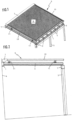
- a terrace roof construction which has horizontal purlins 1 and rafters 2 running transversely to these.
- the front purlin 1 is supported on vertical columns 3.
- the rear purlin 1 is attached to a building wall 4.
- the purlins 1 are offset in height from one another so that the rafters 2 slope from the back to the front.
- the spaces between the rafters 2 are filled with panel-shaped glass roof elements 5 supported by them.
- a so-called terrace roof awning 6 is assigned to the glass roof thus formed to enable shading.
- FIG. 1 This contains a Figures 1 and 2
- An awning fabric 8 which can be accommodated in a housing 7 (not shown in more detail) which is located in the area of the rear edge of the glass roof and which is rotatably mounted on a winding shaft, the front end of which is fastened to a tension profile 9 which is parallel to the winding shaft and which is guided with its lateral ends or runners attached to it in guide rails 10 which run in the direction of projection of the awning fabric 8 and protrude from the housing 7 fastened to it.
- the guide rails 10 are accommodated and spaced apart from a part of the patio roof construction located underneath, here in the form of a rafter 2, by means of support feet 11 which protrude from their underside and are distributed over their length.
- the support feet 11 are removable elements which can be detachably screwed onto the associated guide rail 10 from below and can also be screwed onto or removed from the associated rafter 8 etc. from above.
- the guide rails 10 and the housing attached to them are connected to the terrace roof structure with a roof clearance via the support feet 11.
- the guide rails 10 and the housing 7 are firmly connected to one another.
- the housing 7 therefore protrudes cantilevered from the rear without touching the elements of the terrace roof structure. End of the guide rails 10.
- the support feet 11, by means of which the guide rails 10 are attached parallel to the rafters to the terrace roof construction located underneath, have a corresponding length.
- the housing 7 is supported by a Figure 3 indicated, parallel to the winding shaft pivot axis 17 is pivotally mounted on the associated wall brackets 15.
- the front end areas of the guide rails 10 are each connected to the support structure formed here by the supports 16 via a tilting axis 18 containing a tilting joint 19.
- the tilting joint 19 for the terrace roof awning according to Figures 1 and 2 The support feet 11 required are not required here and can therefore be removed.
- the wall brackets 15 and tilting joints 16 are used here as supporting elements.
- the bearing block 20 and the hinge part 21 associated with it are pivotally connected to one another by a bearing pin 17a which passes through these two elements and contains the pivot axis 17 and is parallel to the winding shaft.
- the housing 7 of the awning is accommodated on the pivot pieces 22 of the wall brackets 5, of which several, at least two, can be provided over the length of the housing.
- the pivot piece 22 of each wall bracket 15 is designed as a shell element which surrounds a facing, rear housing area of the housing 7.
- the pivot piece 22 is designed as a half or partial shell that encompasses the rear, lower corner area of the housing 7, against which the housing 7 rests snugly.
- the half or partial shell that forms the pivot piece 22 has two arms 23, 24 that run away from the pivot bearing in opposite directions, namely an upper arm 23 and a lower arm 24.
- the housing 7 can be suspended at the upper end of the upper arm 23 of the pivot pieces 22 of the wall brackets 15.
- a suspension claw 25 formed by a rearward-facing bend is provided at the upper end of the upper arm 23.
- the housing 7 is provided in the rear area associated with the upper end of the pivot piece 22 with a correspondingly undercut hanging groove 26 associated with the hanging claw 25, which extends over the entire length of the housing, so that the pivot pieces 22 of all the wall brackets 15 provided can be brought into engagement in the same way, regardless of their lateral distance and their distribution over the length of the housing.
- a stop device that limits the pivoting angle of the pivoting pieces 22 with respect to the wall brackets 15.
- the hinge part 21 of the Pivoting pieces 22 are provided with a stop element 27 formed by a radial projection, which interacts with a facing counter surface, here in the form of the groove base of the associated bearing block 20, of the associated wall bracket 15.
- the stop element 27 is located in the lower peripheral area of the hinge part 21 and is dimensioned in height such that a maximum pivoting angle of 45° is possible with respect to the housing wall 14, i.e.
- the swivel pieces 22 of the wall brackets 15 are screwed to the housing 7.
- the housing 7 is provided with a T-slot 28, which is spaced from the hanging groove 26 and, like the latter, runs along the entire length of the housing.
- slot nuts 29 assigned to the wall brackets 15 can be accommodated, each of which has a threaded hole and can be firmly screwed to the associated swivel piece 22 by means of a screw 30 which can be screwed into the slot and which engages the associated swivel piece 22 and advantageously passes through it.
- This screw connection is expediently assigned to the lower arm 24 of the swivel pieces 22.
- the T-groove 28 is accordingly located in a lower peripheral region of the housing 7 associated with the lower arms 24 of the pivoting pieces 22.
- the front end of the lower arm 24 of the pivoting pieces 22 is tapered in thickness towards its free end, so that a contour is created which runs approximately tangentially into the curved, lower peripheral contour of the housing 7.
- the awning which is pivotably mounted on the associated wall brackets 15 in the area of its rear end, is pivotably mounted at the front via the tilting joint 19 on the associated support device, which is formed here by the posts 16.
- This rear and front Pivoting allows a self-adjusting adjustment of the inclination of the awning 12 to the existing structural conditions.
- the tilting joints 19 assigned to the front end areas of the guide rails 10 are, as best seen from Figure 5 can be seen, designed as two-leg hinge joints, the upper and lower legs of which are pivotally connected to one another by a bearing pin 18a which is parallel to the winding shaft and contains the tilting axis 18, and the upper leg 31 of which can be detachably screwed to the associated guide rail 10 in a similar way to the support feet 11, while the lower leg 32 can be permanently attached to the associated support device or can also be detachably attached thereto.
Landscapes
- Engineering & Computer Science (AREA)
- Architecture (AREA)
- Civil Engineering (AREA)
- Structural Engineering (AREA)
- Building Awnings And Sunshades (AREA)
Description
- Die Erfindung betrifft eine Markise mit einem auf einer in einem Gehäuse angeordneten Wickelwelle aufgenommenen Markisentuch, das mit seinem vorderen Ende an einem Zugprofil angebracht ist, das mit seinen seitlichen Endbereichen in in Ausfallrichtung des Markisentuchs verlaufenden, vom an diesen angebrachten Gehäuse abstehenden Führungsschienen geführt ist, die zur Bildung einer Terrassendachmarkise über lösbar anbringbare Stützen auf einem Terrassendach aufgenommen sind.
- Eine Terrassendachmarkise dieser Art ist beispielsweise aus der
DE 101 50 709 C2 bekannt. Die bekannten Anordnungen dieser Art ermöglichen nur eine Verwendung als Terrassendachmarkise, bei der das die Wickelwelle enthaltende Gehäuse freitragend vom oberen Ende der auf dem Terrassendach montierten Führungsschienen absteht. Eine andere Verwendung ist hier nicht möglich. - Hiervon ausgehend ist es daher die Aufgabe der vorliegenden Erfindung, mit einfachen und kostengünstigen Mitteln auch eine alternative Verwendung einer Markise gattungsgemäßer Art als eine Freifläche etc. übergreifende Pergolamarkise zu ermöglichen.
- Diese Aufgabe wird mit den Merkmalen des Anspruchs 1 gelöst.
- Diese Maßnahmen erweitern unter Zuhilfenahme lediglich weniger Zusatzbauteile das Einsatzgebiet der erfindungsgemäßen Markise, was eine Herstellung in größeren Chargen ermöglicht und die Lagerhaltung vereinfacht und damit insgesamt eine gute Wirtschaftlichkeit gewährleistet. Bei der Montage der erfindungsgemäßen Markise als Pergolamarkise kann das die Wickelwelle enthaltende Gehäuse einfach zum Eingriff mit den Schwenkstücken der bereits vormontierten Wandkonsolen gebracht werden, was bereits einen vorläufigen Halt der gesamten, aus Gehäuse und hieran angebrachten Führungsschienen bestehenden Baueinheit ergibt und damit deren endgültige Montage erleichtert.
- Vorteilhafte Ausgestaltungen und zweckmäßige Fortbildungen der übergeordneten Maßnahmen sind in den Unteransprüchen angegeben.
- So kann den Schwenkstücken jeweils eine ihren Schwenkwinkel gegenüber der zugeordneten Wandkonsole begrenzende Anschlageinrichtung zugeordnet sein. Hierdurch wird sichergestellt, dass die mit ihrem Gehäuse in die Schwenkstücke eingehängte Markise bereits so gehalten wird, dass sie nicht herunter fallen kann und eine bequeme Verschraubung des Gehäuses mit den Schwenkstücken erfolgen kann, was den Gesamtmontagevorgang erleichtert.
- Vorteilhaft weisen die Schwenkstücke jeweils eine durch eine rückwärtige Verdickung gebildete, einem konsolenseitig vorgesehenen Lagerbock zugeordnete und durch einen wickelwellenparallelen Lagerstift hiermit verbundene Lagerfahne auf, die in ihrem unteren Umfangsbereich mit einem tangentialen Vorsprung versehen ist, der zur Bildung einer Anschlageinrichtung mit einer konsolenseitigen Gegenfläche zusammenwirkt. Diese Maßnahmen ergeben eine einfache Integration der Anschlageinrichtung in die Schwenklagerung der Schwenkstücke und damit insgesamt eine einfache Bauweise. Gleichzeitig ist hierdurch sichergestellt, dass die Anschlageinrichtung automatisch wirksam wird.
- In weiterer Fortbildung der übergeordneten Maßnahmen können die vorderen Enden der Führungsschienen jeweils über ein eine wickelwellenparallele Kippachse endhaltendes Kippgelenk an das obere Ende eines zugeordneten Pfostens oder dergleichen anschließbar sein. Die Kippgelenke ergeben zusammen mit der schwenkbaren Lagerung der Schwenkstücke eine hohe Variabilität hinsichtlich der Neigung der so erstellten Pergolamarkise und gewährleisten damit eine einfache Anpassbarkeit an vor Ort vorgefundene, bauliche Gegebenheiten.
- Vorteilhaft können die unteren Arme der Schwenkstücke zu ihrem Ende hin in der Dicke verjüngt sein, so dass sich eine schlanke Ausbildung der den zugewandten Gehäusebereich umfassenden, die Schwenkstücke bildenden Teilschalen ergibt.
- Da die Einhängnut und T-Nut des Gehäuses als über die Länge durchgehende Nuten ausgebildet sind, kann die Anzahl der zum Einsatz kommenden Wandkonsolen in Abhängigkeit von der Länge des Gehäuses frei gewählt werden. Mindestens zwei Wandkonsolen sind im jedem Fall vorgesehen. Bei einer größeren Gehäuselänge können aber auch mehrere, gleichmäßige über die Länge verteilte Wandkonsolen vorgesehen sein.
- Weitere vorteilhafte Ausgestaltungen und zweckmäßige Fortbildungen der übergeordneten Maßnahmen sind in den restlichen Unteransprüchen angegeben und aus der nachstehenden Beispielsbeschreibung anhand der Zeichnung näher entnehmbar.
- In der nachstehend beschriebenen Zeichnung zeigen:
- Figur 1
- eine perspektivische Ansicht einer erfindungsgemäßen Markise als Terrassendachmarkise,
- Figur 2
- eine Seitenansicht der Anordnung gemäß
Figur 1 , - Figur 3
- eine Seitenansicht einer erfindungsgemäßen Markise als Pergolamarkise,
- Figur 4
- eine vergrößerte Darstellung des rückwärtigen Bereichs der Anordnung gemäß
Figur 3 ohne Gehäusedeckel und - Figur 5
- eine vergrößerte Darstellung des vorderen Bereichs der Anordnung gemäß
Figur 3 . - In den
Figuren 1 und 2 ist eine Terrassendachkonstruktion angedeutet, die waagrechte Pfetten 1 und auf diesen aufgenommene quer hierzu verlaufende Sparren 2 aufweist. Die vordere Pfette 1 ist im dargestellten Beispiel auf vertikalen Säulen 3 aufgenommen. Die hintere Pfette 1 ist an einer Gebäudewand 4 befestigt. Die Pfetten 1 sind in der Höhe so gegeneinander versetzt, dass sich ein Gefälle der Sparren 2 von hinten nach vorne ergibt. Die Zwischenräume zwischen den Sparren 2 sind durch hiervon getragene, tafelförmige Glasdachelemente 5 ausgefacht. Dem so gebildeten Glasdach ist zur Ermöglichung einer Verschattung eine sogenannte Terrassendachmarkise 6 zugeordnet. - Diese enthält ein auf einer in den
Figuren 1 und 2 nicht näher dargestellten, im Bereich des hinteren Rands des Glasdachs platzierten Gehäuse 7 drehbar gelagerten Wickelwelle aufnehmbares Markisentuch 8, das mit seinem vorderen Ende an einem wickelwellenparallelen Zugprofil 9 befestigt ist, das mit seinen seitlichen Enden bzw. hieran angebrachten Läufern in in Ausfallrichtung des Markisentuchs 8 verlaufenden, vom hieran befestigten Gehäuse 7 abstehenden Führungsschienen 10 geführt ist. Die Führungsschienen 10 sind mittels von ihrer Unterseite abstehenden, über ihre Länge verteilten Stützfüßen 11 auf einem jeweils darunter sich befindenden Teil der Terrassendachkonstruktion, hier in Form eines Sparrens 2 aufgenommen und hiervon beabstandet. Bei den Stützfüßen 11 handelt es sich um abnehmbare Elemente, die einerseits lösbar von unten an die jeweils zugeordnete Führungsschiene 10 und andererseits von oben an den jeweils zugeordneten Sparren 8 etc. anschraubbar bzw. hiervon abnehmbar sind. Über die Stützfüße 11 sind die Führungsschienen 10 sowie das hieran angebrachte Gehäuse mit Dachabstand tragend mit der Terrassendachkonstruktion verbunden. Die Führungsschienen 10 und das Gehäuse 7 sind fest miteinander verbunden. Das Gehäuse 7 ragt hier daher ohne Berührung der Elemente der Terrassendachkonstruktion freitragend vom hinteren Ende der Führungsschienen 10 ab. Hierzu besitzen die Stützfüße 11, mittels der die Führungsschienen 10 sparrenparallel an der darunter sich befindenden Terrassendachkonstruktion befestigt sind, eine entsprechende Länge. - Zur Erweiterung des Einsatzgebiets der den
Figuren 1 und 2 zugrunde liegenden Terrassendachmarkise 6 kann diese gemäßFiguren 3 bis 5 in eine Pergolamarkise 12 zur Verschattung einer nicht überdachten Freifläche etc. umgebaut werden. Für gleiche Teile finden daher in denFiguren 3 bis 5 dieselben Bezugszeichen wie in denFiguren 1 und 2 Verwendung. Da die Freifläche 13 nicht überdacht ist, wird hier die aus dem Gehäuse 7 und den tragend hiermit verbundenen Führungsschienen 10 gebildete Baueinheit nach Art einer freitragenden Brücke einerseits am hinteren Ende durch an einer die Freifläche 13 begrenzenden Wand 14 anbringbaren Wandkonsolen 15 und andererseits am vorderen Ende durch eine hier durch vertikale Pfosten 16 gebildete Stützkonstruktion abgestützt. Das Gehäuse 7 ist dabei um eine inFigur 3 angedeutete, wickelwellenparallele Schwenkachse 17 schwenkbar auf den zugeordneten Wandkonsolen 15 gelagert. Die vorderen Endbereiche der Führungsschienen 10 sind jeweils über eine wickelwellenparallele Kippachse 18 enthaltende Kippgelenkte 19 an die hier durch die Stützen 16 gebildete Stützkonstruktion angeschlossen. Die bei der Terrassendachmarkise gemäßFiguren 1 und 2 benötigten Stützfüße 11 werden hier nicht benötigt und können daher abgenommen sein. Andererseits werden hier als Stützorgane die Wandkonsolen 15 und Kippgelenke 16 zum Einsatz gebracht. - Die über nicht näher dargestellte Schrauben an der Wand 14 festlegbaren, platten- oder laschenförmigen Wandkonsolen 15 sind, wie am besten aus
Figur 4 erkennbar ist, im Bereich ihres unter Rands mit einem von ihrer wandfernen Seite abstehenden Lagerbock 20 zur schwenkbaren Aufnahme eines jeweils zugeordneten, eine in den Lagerbock 20 eingreifende, Lagerfahne, d. h. ein fahnenartiges Scharnierteil 21 aufweisenden, zweiarmigen Schwenkstücks 22 versehen. Der Lagerbock 20 und das diesem zugeordnete Scharnierteil 21 sind durch einen diese beiden Organe durchgreifenden, die Schwenkachse 17 enthaltenden, wickelwellenparallelen Lagerstift 17a schwenkbar miteinander verbunden. Das Gehäuse 7 der Markise wird auf den Schwenkstücken 22 der Wandkonsolen 5, von denen über der Gehäuselänge mehrere, mindestens zwei, vorgesehen sein können, aufgenommen. Zur Bildung einer schlanken Anordnung ist das Schwenkstück 22 jeder Wandkonsole 15 dabei als einen zugewandten, hinteren Gehäusebereich des Gehäuses 7 umgreifendes Schalenelement ausgebildet. - Im dargestellten Beispiel ist das Schwenkstück 22 als den hinteren, unteren Eckbereich des Gehäuses 7 umfassende Halb- bzw. Teilschale ausgebildet, an der das Gehäuse 7 satt anliegt. Die das Schwenkstück 22 bildende Halb- bzw. Teilschale besitzt zwei Arme 23, 24, die gegenläufig von der Schwenklagerung weglaufen, nämlich einen oberen Arm 23 und einen unteren Arm 24. Am oberen Ende des oberen Arms 23 der Schwenkstücke 22 der Wandkonsolen 15 ist das Gehäuse 7 einhängbar. Hierzu ist am oberen Ende des oberen Arms 23 eine durch eine nach hinten weisende Abwinklung gebildete Einhängklaue 25 vorgesehen. Das Gehäuse 7 ist im dem oberen Ende des Schwenkstücks 22 zugeordnet, rückwärtigen Bereich mit einer der Einhängklaue 25 zugeordneten, entsprechend hinterschnittenen Einhängnut 26 versehen, die über die ganze Gehäuselänge durchgeht, so dass die Schwenkstücke 22 sämtlicher vorgesehener Wandkonsolen 15 unabhängig von ihrem seitlichen Abstand und ihrer Verteilung über die Gehäuselänge in gleicher Weise zum Eingriff gebracht werden können.
- Durch Einhängung des Gehäuses 7 an den oberen Enden der Schwenkstücke 22 ergibt sich bereits eine lose Aufhängung des Gehäuses 7 und dementsprechend der gesamten Markise. Um dabei einem Absturz vorzubeugen ist eine den Schwenkwinkel der Schwenkstücke 22 gegenüber den Wandkonsolen 15 begrenzende Anschlageinrichtung vorgesehen. Hierzu ist im dargestellten Beispiel das durch eine rückwärtige Verdickung gebildete Scharnierteil 21 der Schwenkstücke 22 mit einem durch einen radialen Vorsprung gebildeten Anschlagelement 27 versehen, das mit einer zugewandten Gegenfläche, hier in Form des Nutgrunds des zugeordneten Lagerbocks 20, der zugeordneten Wandkonsole 15 zusammenwirkt. Das Anschlagelement 27 befindet sich im unteren Umfangsbereich des Scharnierteils 21 und ist in der Höhe so bemessen, dass ein maximaler Schwenkwinkel von 45° gegenüber der Gehäusewand 14, d. h. gegenüber den an der Gehäusewand 14 angebrachten Wandkonsolen 15 möglich ist. Hierdurch ergibt sich einerseits ein ausreichend großer Einstellbereich zur Einstellung der gewünschten Neigung der Markise 12 und andererseits in der unteren Endstellung eine günstige Position der Markise 12 für weitere Montagearbeiten zur sicheren Befestigung des Gehäuses 7 auf den Schwenkstücken 22 der Wandkonsolen 15.
- Hierzu findet eine Verschraubung der Schwenkstücke 22 der Wandkonsolen 15 mit dem Gehäuse 7 statt. Hierzu ist das Gehäuse 7 mit einer von der Einhängnut 26 entfernten, wie diese über die ganze Gehäuselänge durchgehenden T-Nut 28 versehen, in der den Wandkonsolen 15 zugeordnete Nutensteine 29 aufnehmbar sind, die jeweils eine Gewindebohrung aufweisen, und mittels einer in diese eindrehbaren, am zugeordneten Schwenkstück 22 angreifenden, vorteilhaft dieses durchgreifenden Schraube 30 fest hiermit verschraubbar sind. Diese Verschraubung ist zweckmäßig dem unteren Arm 24 der Schwenkstücke 22 zugeordnet. Die T-Nut 28 befindet sich dementsprechend in einem den unteren Armen 24 der Schwenkstücke 22 zugeordneten, unteren Umfangsbereich des Gehäuses 7. Das vordere Ende des unteren Arms 24 der Schwenkstücke 22 ist zu seinem freien Ende hin in der Dicke verjüngt, so dass sich eine etwa tangential in die gewölbte, untere Umfangskontur des Gehäuses 7 einlaufende Kontur ergibt.
- Die im Bereich ihres hinteren Endes schwenkbar auf den zugeordneten Wandkonsolen 15 aufgenommene Markise ist vorne über die Kippgelenkte 19 schwenkbar an der zugeordneten, hier durch die Pfosten 16 gebildeten Stützeinrichtung aufgenommen. Diese hinten und vorne vorgesehene Schwenkbarkeit ermöglicht eine sich selbst einstellende Anpassung der Neigung der Markise 12 an die vorgefundenen, baulichen Gegebenheiten. Die den vorderen Endbereichen der Führungsschienen 10 zugeordneten Kippgelenke 19 sind, wie am besten aus
Figur 5 ersichtlich ist, als zweischenklige Scharniergelenke ausgebildet, deren oberer und untere Schenkel durch einen wickelwellenparallelen, die Kippachse 18 enthaltenden Lagerbolzen 18a schwenkbar miteinander verbunden sind und deren oberer Schenkel 31 ähnlich wie die Stützfüße 11 lösbar an die zugeordnete Führungsschiene 10 anschraubbar sind, während der untere Schenkel 32 bleibend an der zugeordneten Stützeinrichtung angebracht oder ebenfalls lösbar hieran anbringbar sein kann. - Die Zeichnungen lassen in Verbindung mit der obigen Beschreibung erkennen, dass ein und dieselbe Markise sowohl als Terrassendachmarkise 6 als auch als Pergolamarkise 12 verwendbar ist, wobei bei der Verwendung als Terrassendachmarkise lediglich die Stützfüße 11 und bei der Verwendung als Pergolamarkise lediglich die mit jeweils einem Schwenkstück 22 versehenen Wandkonsolen 15 und die Kippgelenke 19 als alternative Hilfselemente zum Einsatz kommen.
Claims (7)
- Markise, die unter Verwendung alternativer Hilfselemente von einer Terrassendachmarkise in eine Pergolamarkise umbaubar ist, mit einem auf einer in einem Gehäuse (7) angeordneten Wickelwelle aufgenommenen Markisentuch, das mit seinem vorderen Ende an einem Zugprofil (9) angebracht ist, das mit seinen seitlichen Endbereichen in in Ausfallrichtung des Markisentuchs verlaufenden, vom an diesen angebrachten Gehäuse (7) abstehenden Führungsschienen (10) geführt ist, die zur Bildung einer Terrassendachmarkise (6) über lösbar angebrachte Stützen (11) auf einem Terrassendach aufgenommen sind und die zur Bildung einer Pergolamarkise (12) ohne die Stützen (11) nur im Bereich ihrer vorderen Enden lösbar an das oberere Ende einer jeweils zugeordneten Abstützung angeschlossen sind, wobei das Gehäuse (7) auf lösbar hieran angebrachten Wandkonsolen (15) aufgenommen ist, die jeweils ein um eine durch einen wickelwellenparallelen Lagerstift (17a) gebildete Achse schwenkbar gelagertes Schwenkstück (22) aufweisen, das als einen zugewandten hinteren Bereich des Gehäuses (7) umgreifende lösbar hieran festgelegte Teilschale ausgebildet ist, die als zweiarmiger Schwenkhebel mit zwei gegenläufig von der Schwenklagerung abgehenden Armen (23, 24) ausgebildet ist, wobei am oberen Ende des oberen Arms (23) eine durch eine rückwärtige, nach hinten weisende Abwinklung gebildete Einhängklaue (25) vorgesehen ist, an welcher das Gehäuse (7) einhängbar ist, das dazu im dem oberen Ende der Schwenkstücke (22) zugeordneten rückwärtigen Bereich mit einer der Einhängklaue (25) zugeordneten, entsprechend hinterschnittenen, durchgehenden Einhängnut (26) versehen ist, wobei das Gehäuse (7) in einem den unteren Armen (24) der Schwenkstücke (22) zugeordneten Umfangsbereich mit einer von der Einhängnut (26) entfernten, durchgehenden T-Nut versehen ist, in welcher den Schwenkstücken (22) zugeordnete Nutensteine (29) aufnehmbar sind, die mit einer Gewindebohrung versehen sind, in welche jeweils eine am zugeordneten Schwenkstück (22) angreifende Halteschraube (30) einschraubbar ist.
- Markise nach Anspruch 1, dadurch gekennzeichnet, dass den Schwenkstücken (22) der Wandkonsolen (15) jeweils eine ihren Schwenkwinkel gegenüber der zugeordneten Wandkonsole (15) begrenzende Anschlageinrichtung zugeordnet ist.
- Markise nach Anspruch 2, dadurch gekennzeichnet, dass die Schwenkstücke (22) jeweils eine durch eine rückwärtige Verdickung gebildete, einem konsolenseitig vorgesehenen Lagerbock (20) zugeordnete und durch einen wickelwellenparallelen Lagerstift (17a) hiermit verbundene Lagerfahne (21) aufweist, die in ihrem unteren Umfangsbereich mit einem tangentialen Vorsprung (27) versehen ist, der zur Bildung einer Anschlageinrichtung mit einer konsolenseitigen Gegenfläche zusammenwirkt.
- Markise nach einem der vorhergehenden Ansprüche, dadurch gekennzeichnet, dass die vorderen Enden der Führungsschienen (10) jeweils über ein eine wickelwellenparallele Kippachse enthaltendes Kippgelenk (19) an das obere Ende eines zugeordneten Pfostens (16) etc. anschließbar sind.
- Markise nach einem der vorhergehenden Ansprüche, dadurch gekennzeichnet, dass die T-Nut (28) dem unteren, am unteren Arm (24) der Schwenkstücke (22) zur Anlage kommenden Umfangsbereich des Gehäuses (7) zugeordnet ist.
- Markise nach einem der vorhergehenden Ansprüche, dadurch gekennzeichnet, dass der untere Arm (24) der Schwenkstücke (22) zu seinem freien Ende hin in der Dicke verjüngt ist.
- Markise nach einem der vorhergehenden Ansprüche, dadurch gekennzeichnet, dass die Einhängnut (26) und T-Nut (28) des Gehäuses (7) über die Gehäuselänge durchgehen und das über der Gehäuselänge mehrere Wandkonsolen (15) vorgesehen sind.
Applications Claiming Priority (1)
| Application Number | Priority Date | Filing Date | Title |
|---|---|---|---|
| DE202017005991.6U DE202017005991U1 (de) | 2017-11-20 | 2017-11-20 | Markise |
Publications (3)
| Publication Number | Publication Date |
|---|---|
| EP3486397A1 EP3486397A1 (de) | 2019-05-22 |
| EP3486397B1 EP3486397B1 (de) | 2020-09-23 |
| EP3486397B2 true EP3486397B2 (de) | 2024-08-21 |
Family
ID=60782760
Family Applications (1)
| Application Number | Title | Priority Date | Filing Date |
|---|---|---|---|
| EP18020594.0A Active EP3486397B2 (de) | 2017-11-20 | 2018-11-13 | Markise |
Country Status (3)
| Country | Link |
|---|---|
| EP (1) | EP3486397B2 (de) |
| DE (1) | DE202017005991U1 (de) |
| ES (1) | ES2830772T5 (de) |
Families Citing this family (2)
| Publication number | Priority date | Publication date | Assignee | Title |
|---|---|---|---|---|
| DE202019002242U1 (de) | 2019-05-22 | 2019-06-07 | Erhardt Markisenbau Gmbh | Vorrichtung zur Verschattung einer Freifläche |
| DE102020134445A1 (de) | 2020-12-21 | 2022-06-23 | Warema Renkhoff Se | Tragkonsole mit schwenkbarer Lagerung zur Anbringung eines Gehäuses einer Sonnenschutzanlage |
Citations (3)
| Publication number | Priority date | Publication date | Assignee | Title |
|---|---|---|---|---|
| DE10233144A1 (de) † | 2002-07-19 | 2004-02-05 | Weinor Dieter Weiermann Gmbh & Co. | Ausfahrbarer Sonnenschutz |
| DE202010011307U1 (de) † | 2009-08-31 | 2010-11-04 | Schmitz-Werke Gmbh + Co Kg | Freisitz-Überdachung nach Art einer Wintergartenmarkise |
| DE202015001293U1 (de) † | 2015-02-20 | 2015-03-16 | Weinor Gmbh & Co. Kg | Markise mit längenveränderbaren senkrechten Stützen |
Family Cites Families (5)
| Publication number | Priority date | Publication date | Assignee | Title |
|---|---|---|---|---|
| DE10150709C2 (de) | 2001-10-13 | 2003-12-11 | Erhardt Markisenbau Gmbh | Markise |
| DE202007006874U1 (de) | 2007-05-12 | 2007-07-19 | Schmitz-Werke Gmbh + Co. Kg | Wintergartenmarkise und Reinigungseinrichtung für eine Wintergartenverglasung |
| PT2253782E (pt) | 2009-05-19 | 2013-11-18 | Pacadar Sa | Estrutura de apoio para uma turbina eólica |
| NL2008366C2 (nl) * | 2012-02-27 | 2013-08-28 | Lewens Sonnenschutz Systeme Gmbh & Co Kg | Aanbouw. |
| ITPD20140018U1 (it) | 2014-03-05 | 2015-09-05 | Gibus Spa | Tenda per esterni |
-
2017
- 2017-11-20 DE DE202017005991.6U patent/DE202017005991U1/de active Active
-
2018
- 2018-11-13 ES ES18020594T patent/ES2830772T5/es active Active
- 2018-11-13 EP EP18020594.0A patent/EP3486397B2/de active Active
Patent Citations (3)
| Publication number | Priority date | Publication date | Assignee | Title |
|---|---|---|---|---|
| DE10233144A1 (de) † | 2002-07-19 | 2004-02-05 | Weinor Dieter Weiermann Gmbh & Co. | Ausfahrbarer Sonnenschutz |
| DE202010011307U1 (de) † | 2009-08-31 | 2010-11-04 | Schmitz-Werke Gmbh + Co Kg | Freisitz-Überdachung nach Art einer Wintergartenmarkise |
| DE202015001293U1 (de) † | 2015-02-20 | 2015-03-16 | Weinor Gmbh & Co. Kg | Markise mit längenveränderbaren senkrechten Stützen |
Non-Patent Citations (2)
| Title |
|---|
| Druckschrift „ Plaza Viva - die textile Pergola-Markise",Preisliste und technische Informationen 2017 [Auszug],Stand 10. April 2017, gültig vom 01.04 2017 bis zum 31.12.2017 (weinor GmbH & Co. KG) † |
| Druckschrift!, Wintergarten-Markisen. WGM 1030/WGM2030 Design. 04/2015 † |
Also Published As
| Publication number | Publication date |
|---|---|
| DE202017005991U1 (de) | 2017-12-07 |
| EP3486397B1 (de) | 2020-09-23 |
| ES2830772T5 (en) | 2025-01-29 |
| EP3486397A1 (de) | 2019-05-22 |
| ES2830772T3 (es) | 2021-06-04 |
Similar Documents
| Publication | Publication Date | Title |
|---|---|---|
| DE3711609C2 (de) | ||
| EP3161390B1 (de) | Schräganordnung von pv-modulen auf flachdächern | |
| EP3341538B1 (de) | Fächerförmige fahrzeugmarkise | |
| EP3486397B2 (de) | Markise | |
| DE3323012C2 (de) | ||
| DE10262175C5 (de) | Antennenhalter | |
| EP2348167A2 (de) | Anordnung von Dacheindeckelementen auf einer Dachunterkonstruktion | |
| DE19816529C2 (de) | Balkonkonstruktion | |
| CH655757A5 (en) | Awning | |
| DE69415478T2 (de) | Immobilisierungsvorrichtung einer vertikalen Geländerversteifung gegenüber eines Bodenständers | |
| DE29606112U1 (de) | Kantenschalung | |
| EP0231485A2 (de) | Dachabdeckungsbaustein | |
| DE3406027C2 (de) | Schwenkbare Fensterbank | |
| DE102011121548B4 (de) | Befestigungselement,Befestigungsanordnung und Überdachung | |
| DE4439788C1 (de) | Gelenkarmmarkise | |
| EP3722529B1 (de) | Überdachungssystem | |
| EP1104829B1 (de) | Kastenmarkise | |
| EP0666951B1 (de) | Dachrinnenhalterung | |
| DE202018000706U1 (de) | Strukturanordnung, Überdachungsvorrichtung | |
| EP1724411B1 (de) | Gelenkarm-markise | |
| DE29811284U1 (de) | Dachkonstruktion mit Traufstück | |
| EP2574257B1 (de) | Fensterdekoration | |
| DE202021105665U1 (de) | Tragstruktur für ein Vordach | |
| DE2750729A1 (de) | Verbesserter dachraumluefter | |
| DD237110A1 (de) | Zusammenklappbarer tisch |
Legal Events
| Date | Code | Title | Description |
|---|---|---|---|
| PUAI | Public reference made under article 153(3) epc to a published international application that has entered the european phase |
Free format text: ORIGINAL CODE: 0009012 |
|
| STAA | Information on the status of an ep patent application or granted ep patent |
Free format text: STATUS: THE APPLICATION HAS BEEN PUBLISHED |
|
| STAA | Information on the status of an ep patent application or granted ep patent |
Free format text: STATUS: REQUEST FOR EXAMINATION WAS MADE |
|
| AK | Designated contracting states |
Kind code of ref document: A1 Designated state(s): AL AT BE BG CH CY CZ DE DK EE ES FI FR GB GR HR HU IE IS IT LI LT LU LV MC MK MT NL NO PL PT RO RS SE SI SK SM TR |
|
| AX | Request for extension of the european patent |
Extension state: BA ME |
|
| 17P | Request for examination filed |
Effective date: 20190508 |
|
| RBV | Designated contracting states (corrected) |
Designated state(s): AL AT BE BG CH CY CZ DE DK EE ES FI FR GB GR HR HU IE IS IT LI LT LU LV MC MK MT NL NO PL PT RO RS SE SI SK SM TR |
|
| STAA | Information on the status of an ep patent application or granted ep patent |
Free format text: STATUS: EXAMINATION IS IN PROGRESS |
|
| 17Q | First examination report despatched |
Effective date: 20191113 |
|
| GRAP | Despatch of communication of intention to grant a patent |
Free format text: ORIGINAL CODE: EPIDOSNIGR1 |
|
| STAA | Information on the status of an ep patent application or granted ep patent |
Free format text: STATUS: GRANT OF PATENT IS INTENDED |
|
| INTG | Intention to grant announced |
Effective date: 20200506 |
|
| GRAS | Grant fee paid |
Free format text: ORIGINAL CODE: EPIDOSNIGR3 |
|
| GRAA | (expected) grant |
Free format text: ORIGINAL CODE: 0009210 |
|
| STAA | Information on the status of an ep patent application or granted ep patent |
Free format text: STATUS: THE PATENT HAS BEEN GRANTED |
|
| AK | Designated contracting states |
Kind code of ref document: B1 Designated state(s): AL AT BE BG CH CY CZ DE DK EE ES FI FR GB GR HR HU IE IS IT LI LT LU LV MC MK MT NL NO PL PT RO RS SE SI SK SM TR |
|
| REG | Reference to a national code |
Ref country code: GB Ref legal event code: FG4D Free format text: NOT ENGLISH |
|
| REG | Reference to a national code |
Ref country code: CH Ref legal event code: EP |
|
| REG | Reference to a national code |
Ref country code: DE Ref legal event code: R096 Ref document number: 502018002497 Country of ref document: DE |
|
| REG | Reference to a national code |
Ref country code: IE Ref legal event code: FG4D Free format text: LANGUAGE OF EP DOCUMENT: GERMAN |
|
| REG | Reference to a national code |
Ref country code: CH Ref legal event code: NV Representative=s name: PATENTANWAELTE MUNK, DE Ref country code: AT Ref legal event code: REF Ref document number: 1316515 Country of ref document: AT Kind code of ref document: T Effective date: 20201015 |
|
| REG | Reference to a national code |
Ref country code: NL Ref legal event code: FP |
|
| REG | Reference to a national code |
Ref country code: GR Ref legal event code: EP Ref document number: 20200402830 Country of ref document: GR Effective date: 20201116 |
|
| PG25 | Lapsed in a contracting state [announced via postgrant information from national office to epo] |
Ref country code: NO Free format text: LAPSE BECAUSE OF FAILURE TO SUBMIT A TRANSLATION OF THE DESCRIPTION OR TO PAY THE FEE WITHIN THE PRESCRIBED TIME-LIMIT Effective date: 20201223 Ref country code: FI Free format text: LAPSE BECAUSE OF FAILURE TO SUBMIT A TRANSLATION OF THE DESCRIPTION OR TO PAY THE FEE WITHIN THE PRESCRIBED TIME-LIMIT Effective date: 20200923 Ref country code: HR Free format text: LAPSE BECAUSE OF FAILURE TO SUBMIT A TRANSLATION OF THE DESCRIPTION OR TO PAY THE FEE WITHIN THE PRESCRIBED TIME-LIMIT Effective date: 20200923 Ref country code: SE Free format text: LAPSE BECAUSE OF FAILURE TO SUBMIT A TRANSLATION OF THE DESCRIPTION OR TO PAY THE FEE WITHIN THE PRESCRIBED TIME-LIMIT Effective date: 20200923 Ref country code: BG Free format text: LAPSE BECAUSE OF FAILURE TO SUBMIT A TRANSLATION OF THE DESCRIPTION OR TO PAY THE FEE WITHIN THE PRESCRIBED TIME-LIMIT Effective date: 20201223 |
|
| PG25 | Lapsed in a contracting state [announced via postgrant information from national office to epo] |
Ref country code: LV Free format text: LAPSE BECAUSE OF FAILURE TO SUBMIT A TRANSLATION OF THE DESCRIPTION OR TO PAY THE FEE WITHIN THE PRESCRIBED TIME-LIMIT Effective date: 20200923 Ref country code: RS Free format text: LAPSE BECAUSE OF FAILURE TO SUBMIT A TRANSLATION OF THE DESCRIPTION OR TO PAY THE FEE WITHIN THE PRESCRIBED TIME-LIMIT Effective date: 20200923 |
|
| REG | Reference to a national code |
Ref country code: LT Ref legal event code: MG4D |
|
| PG25 | Lapsed in a contracting state [announced via postgrant information from national office to epo] |
Ref country code: LT Free format text: LAPSE BECAUSE OF FAILURE TO SUBMIT A TRANSLATION OF THE DESCRIPTION OR TO PAY THE FEE WITHIN THE PRESCRIBED TIME-LIMIT Effective date: 20200923 Ref country code: SM Free format text: LAPSE BECAUSE OF FAILURE TO SUBMIT A TRANSLATION OF THE DESCRIPTION OR TO PAY THE FEE WITHIN THE PRESCRIBED TIME-LIMIT Effective date: 20200923 Ref country code: EE Free format text: LAPSE BECAUSE OF FAILURE TO SUBMIT A TRANSLATION OF THE DESCRIPTION OR TO PAY THE FEE WITHIN THE PRESCRIBED TIME-LIMIT Effective date: 20200923 Ref country code: RO Free format text: LAPSE BECAUSE OF FAILURE TO SUBMIT A TRANSLATION OF THE DESCRIPTION OR TO PAY THE FEE WITHIN THE PRESCRIBED TIME-LIMIT Effective date: 20200923 Ref country code: PT Free format text: LAPSE BECAUSE OF FAILURE TO SUBMIT A TRANSLATION OF THE DESCRIPTION OR TO PAY THE FEE WITHIN THE PRESCRIBED TIME-LIMIT Effective date: 20210125 Ref country code: CZ Free format text: LAPSE BECAUSE OF FAILURE TO SUBMIT A TRANSLATION OF THE DESCRIPTION OR TO PAY THE FEE WITHIN THE PRESCRIBED TIME-LIMIT Effective date: 20200923 |
|
| PG25 | Lapsed in a contracting state [announced via postgrant information from national office to epo] |
Ref country code: IS Free format text: LAPSE BECAUSE OF FAILURE TO SUBMIT A TRANSLATION OF THE DESCRIPTION OR TO PAY THE FEE WITHIN THE PRESCRIBED TIME-LIMIT Effective date: 20210123 Ref country code: PL Free format text: LAPSE BECAUSE OF FAILURE TO SUBMIT A TRANSLATION OF THE DESCRIPTION OR TO PAY THE FEE WITHIN THE PRESCRIBED TIME-LIMIT Effective date: 20200923 Ref country code: AL Free format text: LAPSE BECAUSE OF FAILURE TO SUBMIT A TRANSLATION OF THE DESCRIPTION OR TO PAY THE FEE WITHIN THE PRESCRIBED TIME-LIMIT Effective date: 20200923 |
|
| REG | Reference to a national code |
Ref country code: ES Ref legal event code: FG2A Ref document number: 2830772 Country of ref document: ES Kind code of ref document: T3 Effective date: 20210604 |
|
| REG | Reference to a national code |
Ref country code: DE Ref legal event code: R026 Ref document number: 502018002497 Country of ref document: DE |
|
| PLBI | Opposition filed |
Free format text: ORIGINAL CODE: 0009260 |
|
| PLAB | Opposition data, opponent's data or that of the opponent's representative modified |
Free format text: ORIGINAL CODE: 0009299OPPO |
|
| PG25 | Lapsed in a contracting state [announced via postgrant information from national office to epo] |
Ref country code: MC Free format text: LAPSE BECAUSE OF FAILURE TO SUBMIT A TRANSLATION OF THE DESCRIPTION OR TO PAY THE FEE WITHIN THE PRESCRIBED TIME-LIMIT Effective date: 20200923 Ref country code: SK Free format text: LAPSE BECAUSE OF FAILURE TO SUBMIT A TRANSLATION OF THE DESCRIPTION OR TO PAY THE FEE WITHIN THE PRESCRIBED TIME-LIMIT Effective date: 20200923 |
|
| PLAX | Notice of opposition and request to file observation + time limit sent |
Free format text: ORIGINAL CODE: EPIDOSNOBS2 |
|
| 26 | Opposition filed |
Opponent name: WEINOR GMBH & CO. KG Effective date: 20210617 |
|
| R26 | Opposition filed (corrected) |
Opponent name: WEINOR GMBH & CO. KG Effective date: 20210617 |
|
| PG25 | Lapsed in a contracting state [announced via postgrant information from national office to epo] |
Ref country code: LU Free format text: LAPSE BECAUSE OF NON-PAYMENT OF DUE FEES Effective date: 20201113 |
|
| PLBB | Reply of patent proprietor to notice(s) of opposition received |
Free format text: ORIGINAL CODE: EPIDOSNOBS3 |
|
| PG25 | Lapsed in a contracting state [announced via postgrant information from national office to epo] |
Ref country code: SI Free format text: LAPSE BECAUSE OF FAILURE TO SUBMIT A TRANSLATION OF THE DESCRIPTION OR TO PAY THE FEE WITHIN THE PRESCRIBED TIME-LIMIT Effective date: 20200923 Ref country code: DK Free format text: LAPSE BECAUSE OF FAILURE TO SUBMIT A TRANSLATION OF THE DESCRIPTION OR TO PAY THE FEE WITHIN THE PRESCRIBED TIME-LIMIT Effective date: 20200923 |
|
| PG25 | Lapsed in a contracting state [announced via postgrant information from national office to epo] |
Ref country code: IE Free format text: LAPSE BECAUSE OF NON-PAYMENT OF DUE FEES Effective date: 20201113 |
|
| PG25 | Lapsed in a contracting state [announced via postgrant information from national office to epo] |
Ref country code: TR Free format text: LAPSE BECAUSE OF FAILURE TO SUBMIT A TRANSLATION OF THE DESCRIPTION OR TO PAY THE FEE WITHIN THE PRESCRIBED TIME-LIMIT Effective date: 20200923 Ref country code: MT Free format text: LAPSE BECAUSE OF FAILURE TO SUBMIT A TRANSLATION OF THE DESCRIPTION OR TO PAY THE FEE WITHIN THE PRESCRIBED TIME-LIMIT Effective date: 20200923 Ref country code: CY Free format text: LAPSE BECAUSE OF FAILURE TO SUBMIT A TRANSLATION OF THE DESCRIPTION OR TO PAY THE FEE WITHIN THE PRESCRIBED TIME-LIMIT Effective date: 20200923 |
|
| PG25 | Lapsed in a contracting state [announced via postgrant information from national office to epo] |
Ref country code: MK Free format text: LAPSE BECAUSE OF FAILURE TO SUBMIT A TRANSLATION OF THE DESCRIPTION OR TO PAY THE FEE WITHIN THE PRESCRIBED TIME-LIMIT Effective date: 20200923 |
|
| PLAY | Examination report in opposition despatched + time limit |
Free format text: ORIGINAL CODE: EPIDOSNORE2 |
|
| PLBC | Reply to examination report in opposition received |
Free format text: ORIGINAL CODE: EPIDOSNORE3 |
|
| PUAH | Patent maintained in amended form |
Free format text: ORIGINAL CODE: 0009272 |
|
| STAA | Information on the status of an ep patent application or granted ep patent |
Free format text: STATUS: PATENT MAINTAINED AS AMENDED |
|
| 27A | Patent maintained in amended form |
Effective date: 20240821 |
|
| AK | Designated contracting states |
Kind code of ref document: B2 Designated state(s): AL AT BE BG CH CY CZ DE DK EE ES FI FR GB GR HR HU IE IS IT LI LT LU LV MC MK MT NL NO PL PT RO RS SE SI SK SM TR |
|
| REG | Reference to a national code |
Ref country code: DE Ref legal event code: R102 Ref document number: 502018002497 Country of ref document: DE |
|
| REG | Reference to a national code |
Ref country code: NL Ref legal event code: FP |
|
| REG | Reference to a national code |
Ref country code: ES Ref legal event code: DC2A Ref document number: 2830772 Country of ref document: ES Kind code of ref document: T5 Effective date: 20250129 |
|
| REG | Reference to a national code |
Ref country code: GR Ref legal event code: EP Ref document number: 20240402393 Country of ref document: GR Effective date: 20250314 |
|
| REG | Reference to a national code |
Ref country code: CH Ref legal event code: U11 Free format text: ST27 STATUS EVENT CODE: U-0-0-U10-U11 (AS PROVIDED BY THE NATIONAL OFFICE) Effective date: 20251201 |
|
| PGFP | Annual fee paid to national office [announced via postgrant information from national office to epo] |
Ref country code: NL Payment date: 20251119 Year of fee payment: 8 |
|
| PGFP | Annual fee paid to national office [announced via postgrant information from national office to epo] |
Ref country code: DE Payment date: 20251130 Year of fee payment: 8 |
|
| PGFP | Annual fee paid to national office [announced via postgrant information from national office to epo] |
Ref country code: GB Payment date: 20251120 Year of fee payment: 8 |
|
| PGFP | Annual fee paid to national office [announced via postgrant information from national office to epo] |
Ref country code: AT Payment date: 20251117 Year of fee payment: 8 |
|
| PGFP | Annual fee paid to national office [announced via postgrant information from national office to epo] |
Ref country code: IT Payment date: 20251128 Year of fee payment: 8 |
|
| PGFP | Annual fee paid to national office [announced via postgrant information from national office to epo] |
Ref country code: FR Payment date: 20251120 Year of fee payment: 8 |
|
| PGFP | Annual fee paid to national office [announced via postgrant information from national office to epo] |
Ref country code: BE Payment date: 20251118 Year of fee payment: 8 Ref country code: GR Payment date: 20251117 Year of fee payment: 8 |
|
| PGFP | Annual fee paid to national office [announced via postgrant information from national office to epo] |
Ref country code: CH Payment date: 20251201 Year of fee payment: 8 |
|
| PGFP | Annual fee paid to national office [announced via postgrant information from national office to epo] |
Ref country code: ES Payment date: 20251216 Year of fee payment: 8 |