EP3468418B1 - Adjustable bed - Google Patents
Adjustable bed Download PDFInfo
- Publication number
- EP3468418B1 EP3468418B1 EP17732159.3A EP17732159A EP3468418B1 EP 3468418 B1 EP3468418 B1 EP 3468418B1 EP 17732159 A EP17732159 A EP 17732159A EP 3468418 B1 EP3468418 B1 EP 3468418B1
- Authority
- EP
- European Patent Office
- Prior art keywords
- adjustable
- support section
- mattress
- backrest
- bed
- Prior art date
- Legal status (The legal status is an assumption and is not a legal conclusion. Google has not performed a legal analysis and makes no representation as to the accuracy of the status listed.)
- Active
Links
Images


Classifications
-
- A—HUMAN NECESSITIES
- A47—FURNITURE; DOMESTIC ARTICLES OR APPLIANCES; COFFEE MILLS; SPICE MILLS; SUCTION CLEANERS IN GENERAL
- A47C—CHAIRS; SOFAS; BEDS
- A47C20/00—Head-, foot- or like rests for beds, sofas or the like
- A47C20/04—Head-, foot- or like rests for beds, sofas or the like with adjustable inclination
- A47C20/041—Head-, foot- or like rests for beds, sofas or the like with adjustable inclination by electric motors
-
- A—HUMAN NECESSITIES
- A47—FURNITURE; DOMESTIC ARTICLES OR APPLIANCES; COFFEE MILLS; SPICE MILLS; SUCTION CLEANERS IN GENERAL
- A47C—CHAIRS; SOFAS; BEDS
- A47C20/00—Head-, foot- or like rests for beds, sofas or the like
- A47C20/04—Head-, foot- or like rests for beds, sofas or the like with adjustable inclination
-
- A—HUMAN NECESSITIES
- A47—FURNITURE; DOMESTIC ARTICLES OR APPLIANCES; COFFEE MILLS; SPICE MILLS; SUCTION CLEANERS IN GENERAL
- A47C—CHAIRS; SOFAS; BEDS
- A47C20/00—Head-, foot- or like rests for beds, sofas or the like
- A47C20/08—Head-, foot- or like rests for beds, sofas or the like with means for adjusting two or more rests simultaneously
- A47C20/10—Head-, foot- or like rests for beds, sofas or the like with means for adjusting two or more rests simultaneously using rods
- A47C20/12—Head-, foot- or like rests for beds, sofas or the like with means for adjusting two or more rests simultaneously using rods using telescopic rods
-
- A—HUMAN NECESSITIES
- A61—MEDICAL OR VETERINARY SCIENCE; HYGIENE
- A61G—TRANSPORT, PERSONAL CONVEYANCES, OR ACCOMMODATION SPECIALLY ADAPTED FOR PATIENTS OR DISABLED PERSONS; OPERATING TABLES OR CHAIRS; CHAIRS FOR DENTISTRY; FUNERAL DEVICES
- A61G7/00—Beds specially adapted for nursing; Devices for lifting patients or disabled persons
- A61G7/002—Beds specially adapted for nursing; Devices for lifting patients or disabled persons having adjustable mattress frame
- A61G7/015—Beds specially adapted for nursing; Devices for lifting patients or disabled persons having adjustable mattress frame divided into different adjustable sections, e.g. for Gatch position
-
- A—HUMAN NECESSITIES
- A47—FURNITURE; DOMESTIC ARTICLES OR APPLIANCES; COFFEE MILLS; SPICE MILLS; SUCTION CLEANERS IN GENERAL
- A47C—CHAIRS; SOFAS; BEDS
- A47C20/00—Head-, foot- or like rests for beds, sofas or the like
- A47C20/02—Head-, foot- or like rests for beds, sofas or the like of detachable type
- A47C20/027—Back supports, e.g. for sitting in bed
Definitions
- This invention relates to adjustable beds and in particular concerns adjustable beds having one or more adjustable support sections which can be moved to adjust the configuration of the bed.
- US2002/0174487 discloses a hospital bed having adjustable back and thigh sections for supporting the occupant in various positions, for example in a flat horizontal position, in a recumbent or semi-recumbent position or simply with the backrest raised.
- the hospital bed of US2002/0174487 comprises a frame having a pair of parallel and spaced apart first and second side frame members; a mattress support deck including an adjustable back; a fixed seat section located adjacent to the back section; and, an adjustable thigh section located adjacent to the seat section.
- the thigh section is movable longitudinally relative to the seat section, to increase the length of the thigh section as it is raised relative to the frame.
- First and second curved tubes are coupled to respective first and second sides of the back section.
- a plurality of rollers are coupled to the first and second side frame members, with the rollers being configured to support the first and second curved tubes to permit movement of the curved tubes and the backrest section relative to the frame.
- a linear actuator is disposed beneath the back rest section and coupled to the first and second tubes to move the back rest section from a horizontal position to an elevated position relative to the frame.
- Two concentric arcuate tubes are provided on each side of the bed which have a radius of curvature centred on a location which emulates the natural hip pivot of a person lying on the mattress of the bed. The tubes are secured between three rollers on each side of the bed.
- Two rollers are located on a bottom side of the radially outer tube, that is to say radially outwards thereof, and the third roller is located on a top side of the radially inner tube.
- Cross-members extend between the tubes. The arrangement provides a so called shear-less pivot mechanism in which the adjustable back section pivots about the natural hip point of the person on the bed.
- the angle of elevation (included angle) between the seat and the raised back support section can cause significant operational problems for both the bed and the occupant.
- the angle of adjustment for the backrest will be up to 65 degrees, that is to say the backrest can be raised up to 65 degrees from the notional horizontal plane of the bed, to raise the occupant from a lying position, to a raised position up to 65 degrees maximum.
- the maximum angle of inclination may be slightly less, for example 50 degrees, 55 degrees or 60 degrees, as dependent on the particular application, whether the bed is for domestic, care home or medical use.
- WO2016/058949 and US2009/178201 describe known adjustable beds.
- a further problem associated with known designs is that the angle of elevation between the seat and the raised back support section is not ideal ergonomically, as it does not allow the mattress to naturally crease around the user's hip joint, so the user has to continually adjust their position as the back rest lifts.
- an adjustable bed which is at least as easy to manufacture, store, transport, deliver and assemble as non-adjustable beds of known designs.
- an adjustable bed is provided as set out in the appended claims.
- the above aspect of the invention provides for one or more intermediary short platform sections (mattress bend support section(s)) between seat and back rest platforms to form an approximate curve, of discrete straight lines, as the back rest and mattress bend support sections are raised.
- This more gently bends the mattress and does not force the mattress to conform to a sharp obtuse angle as in hitherto known arrangements.
- the upper surface of the mattress is therefore more ergonomic, gradually curved and more consistent with human anatomy and the natural pivot point of the hip joint (and does not require the user to adjust position as the bed is raised).
- Less force from the actuator is necessary as it is easier to bend the mattress over a larger distance than to crease it at a sharp point. This has the attendant effect of reducing wear and tear on the operating mechanism, including the motor(s)/actuator(s) of a powered adjustable bed.
- the combined range of adjustment of said backrest and mattress bend support sections is 65 degrees or less with respect to the flat lowered configuration of the bed.
- the combined range of adjustment of the backrest and mattress bend support sections may be 60 degrees or less with respect to the flat lowered configuration of the bed.
- the combined range of adjustment of the backrest and mattress bend support section may be 55 degrees or less with respect to the flat lowered configuration of the bed.
- the combined range of adjustment of the backrest and mattress bend support sections may be 50 degrees or less with respect to the flat lowered configuration of the bed.
- the angular range of adjustment of the backrest support section and the angular range of adjustment of the mattress bend support section are substantially equal.
- the angular range of adjustment of the backrest support section is greater than and the angular range of adjustment of said mattress bend support section.
- the adjustable bed of the present invention may comprise a plurality of adjacent adjustable mattress bend support sections.
- the above aspect of the invention therefore contemplates embodiments having a plurality of adjustable mattress bend support sections which combine to provide an approximate curve of discrete sections to define a gentle curvature of mattress support sections on the underside of the mattress as the bed is adjusted and the mattress raised and lowered.
- the adjustable bed of the present invention may comprise a plurality of adjacent adjustable backrest support sections.
- the above aspect of the invention therefore contemplates embodiments having a plurality of adjustable backrest support sections which combine to provide an approximate curve of discrete sections to define a gentle curvature of mattress support sections on the underside of the mattress as the bed is adjusted and the mattress raised and lowered.
- the adjustable bed of the present invention further comprises at least one non-adjustable support section fixed in relation to the frame.
- the mattress bend support section is disposed between the non-adjustable mattress support section and the backrest support section.
- the above aspect of the invention contemplates embodiments without complex and expensive actuating elements.
- This aspect of the invention can achieve significant weight and cost advantages without compromising performance and durability. This is a particular consideration in the domestic furniture industry where manufacturing cost is often of critical importance to product success in the marketplace.
- a significant advantage of this aspect of the present invention is that the profile of the bed, that is to say the depth dimension of the bed, can be minimised, and thereby a low profile adjustable bed can be realised with attendant storage and shipping cost advantages.
- the depth dimension for shipping purposes is the depth of the bed minus legs or other support means which are shipped unassembled.
- the reduced depth dimension readily enables greater number of units to be shipped in a given 35 space, such as an ISO container or the like.
- the upper body section may further comprise a fixed support section adjacent to the backrest support section, the fixed support section being fixed in relation to the frame adjacent the hinged end of the backrest section to provide at least part of a fixed seat section of the bed.
- the lower body section may further comprise a lower body fixed support section adjacent to the upper body section.
- the upper body fixed support section is preferably hingedly connected to the lower body fixed support section.
- the lower body section of the frame may be non-adjustable.
- the upper and lower hinged body sections of the frame may comprise two separate hinged half sections of the frame.
- the adjustable bed may further comprise locking means for locking the respective upper and lower hinged body sections of the frame together when the bed is unfolded for use.
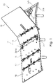
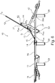
- FIG. 1 to 9 schematically show an adjustable bed 10.
- the bed 10 comprises a mattress support platform or deck 11 having a plurality of adjacent planar mattress support panels, including an adjustable back, neck and head (upper body) support section panel 12, a mattress bend support section panel 13, a non-adjustable intermediate support section panel 14, a non-adjustable lower body support section panel 16, an adjustable thigh section panel 17 and a lower limb and foot support section panel 18.
- the panels 12-18 are shown in ghost outline in order to reveal the detailed construction of the adjustable bed 10.
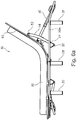
- Figure 6a shows a bed assembly including the adjustable bed 10 in the position of Figure 6 with a mattress 50 supported on the deck 11.
- the mattress 50 is shown slightly elevated above the deck 11 for clarity, although it will be appreciated that the mattress 50 is in direct physical contact with the deck 11 in use.
- the panels 12-18 are mounted on a support frame 20.
- the upper body support panel 12 and mattress bend support panel 13 are adjustably mounted on the support frame 20.
- the intermediate support panel 14 and lower body support section panel 16 are fixed in relation to the frame 20.
- the thigh support panel 17 and lower limb / foot support panel 18 are adjustably mounted on the support frame 20.
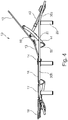
- the mattress bend support section 13 has an upper surface 19, and the backrest support section 14 has an upper surface 21.
- An interior angle B is defined between upper surfaces 19,21, the interior angle B always being less then 180 degrees when the bed moves towards the fully raised configuration such that the backrest section 14 is always tilted towards (anti-clockwise when viewing Figure 4 such that a head of the occupant (not shown) is supported by the backrest support section.
- the frame 20 comprises two half sections 20a, 20b hinged together at their respective adjacent ends.
- the two half sections include a head end sub-assembly 20a and a toe end sub-assembly 20b.
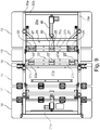
- the two half sections 20a, 20b are hinged together at their respective adjacent ends by hinges 24 fixed to the upward facing surface of the panels 14 and 16 at their respective adjacent edges, as can best be seen in Figures 1 and 10.
- the hinge arrangement is such that the two half sub-assemblies provide a full length structural support frame when hinged apart and locked into position, as shown in the drawings of Figures 1 to 8 .
- the hinged sub-assemblies 20a, 20b allow the upper and lower halves of bed to be folded onto one another, as will be described in greater details below, for transportation, storage, distribution and delivery purposes.
- the upper body support panel 12 and the mattress bend support section panel 13 are adjustably mounted on the head end support frame sub-assembly 20a.
- the intermediate support panel 14 is fixedly mounted on the head end support frame subassembly 20a, adjacent to the mattress bend support panel 13.
- the lower body panel 16 is fixed in relation to the toe end support frame sub-assembly 20b adjacent to the intermediate panel 14.
- the thigh support panel 17 and lower limb / foot support panel 18 are adjustably mounted on the toe end support frame sub-assembly 20b adjacent to the fixed lower body support section panel 16.
- the mattress bend support panel 13 is pivotally connected to the fixed intermediate support by means of a hinged joint 22 extending along the respective adjacent edges of the panels.
- the hinged joint 22 comprises a plurality of hinges 22' spaced along the edges of the adjacent edges of panels 13 and 14 within the region of the frame 20.
- the adjacent edges of the panels 13 and 14 are provided with respective elongate hinge mounting brackets 23a, 23b, preferably of metal construction, which extend on the underside of the panels 13 and 14 between the sides of the frame 20a, as can best be seen in Figure 8 .
- Three hinges 22' are provided, including a centrally located hinge and a pair at the respective ends of the elongate mounting brackets 23a, 23b.
- the hinges 22' are conventional design and construction and are fixedly secured to the respective mounting brackets to pivotally mount the mattress bend support panel to the fixed intermediate support panel about the pivot axis of the hinge 22.
- the upper body support panel 12 is similarly pivotally connected to the mattress bend support panel by means of a hinged joint 25 extending along the respective adjacent edges of the panels.
- the hinged joint 25 comprises a plurality of hinges 25' spaced along the edges of the adjacent edges of panels 12 and 13 within the region of the frame 20.
- the adjacent edges of the panels 12 and 13 are provided with respective elongate hinge mounting brackets 26a, 26b, preferably of metal construction, which extend on the underside of the panels 12 and 13 between the sides of the frame 20a, as can best be seen in Figure 8 .
- Three hinges 25' are provided, including a centrally located hinge and a pair at the respective ends of the elongate mounting brackets 26a, 26b.
- the hinges 25' are conventional design and construction and are fixedly secured to the respective mounting brackets to pivotally mount the upper body support panel 12 to the mattress bend support panel about the pivot axis of the hinge 25.
- Hinges 22' and 25' may be conventional pin bracket type hinges or, in other embodiments, constructed of a fatigue resistant plastics material, for example as a so called "living hinge".
- Other types of hinge are also contemplated including extruded metal tubes, for example extruded aluminium or aluminium alloy, having a d or p shape cross-section, including a longitudinal mounting flange as an integral part of the extrusion, where a hinge pin passes through the extruded tube in a known manner and optionally mounted on bearings (ball bearing type) located at the respective ends of the tube to support the hinge pin in a low friction manner.
- At least hinges 25' are provided with limited angular adjustment so that the adjustable panel 12 has a limited downward angular adjustment with respect to the mattress bend support panel 13.
- the hinge 25 is provided with an abutment stop in the form of a rectangular, preferably metal, plates 27 that are fixedly secured or connected to the hinge mounting bracket 26a in the region of the hinges 25'.
- the plates 27 are positioned on the underside of the hinge 25 and prevent panel 12 being lowered beyond the plane of panel 13 by mutual abutment of the plates 27 and the underside of the mounting brackets 26b. Thus, when the panels 12 and 13 are lowered flat they remain 180 degrees apart.
- Hinges 22' and 25' are also limited upwards so each platform section 12. 13 cannot go beyond this angle relative to the previous panel section it is hinged to (typically 30 degrees, or the total combined angel of angular adjustment divided by the number of intermediary platform sections). Hinges 22' and 25' are also limited downwards so each platform section cannot fall below parallel to the previous section it is hinged to.
- panels 12 and 13 may be raised by a predetermined maximum amount about their respective pivot axis during adjustment of the bed, for example 65 degrees, combined, from the horizontal plane as defined by the flat orientation of fixed intermediate support panels 14 and 16 of the bed.
- Hinges 22 and 25 are provided with stop means to limit the degree of relative angular adjustment of the panels 12 and 13.
- the maximum combined angular adjustment of the panels is 65 degrees with respect to the plane of the fixed non-adjustable panel 14.
- the hinges 22 and 25 may thus be adapted so that they contribute to the maximum angular adjustment of the panels 12 and 13 by equal amounts or substantially equal amounts, for example, 50/50 or 40/60 depending on the particular application and maximum angel of adjustment required.
- the maximum combined angle of adjustment of the backrest and mattress bend support sections is typically 50-65 degrees.
- the angle of adjustment is shared between hinges 22 and 25 connecting each side of the mattress bend support platform.
- the hinge axes are preferably 200 - 300mm apart in the longitudinal direction of the bed, as best seen from the view of Figure 9 .
- a single mattress bend support platform having a length dimension of 250mm is preferred.
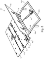
- FIGS 5 and 6 the bed 10 is shown in a fully articulated configuration, adjusted for supporting an occupant in a raised upright seated position.
- the upper body support section panel 12 and the mattress bend support section panel 13 are raised, and inclined with respect to, the fixed intermediate support section panel 14.
- the upper body support section panel 12 is raised about its pivot axis defined by hinge 25 and the mattress bend support panel 13 is raised about its pivot axis defined by hinge 22.
- the combined angle A SB is defined between a plane P s defined by the seat section 16 and a plane P B defined by the backrest support section 12, the combined angle A SB being shared between a first angle A SM defined between the seat section plane P S and a plane P M defined by the mattress bend support section 13, and a second angle A MB defined between the plane P M defined by the mattress support section 13 and the plane P B defined by the backrest support section 12.
- the present invention also contemplates embodiments (not shown) where the lower body support section, or toe end sub-assembly, is non-adjustable, that is to say, non-articulated, or fixed with respect to the frame 20.
- Embodiments of the present invention may therefore provide a bed having an adjustable upper body section only so that the backrest panel 12 and mattress bend panel 13 may be raised to lift the occupant to a seated position, or a bed additionally having an adjustable lower body support section, which may comprise one or more adjustable and non-adjustable mattress support panels as shown in the illustrated embodiment.
- the adjustable support panels 12, 13 combine with the fixed panel 14 and fixed panel or seat section 16 and adjustable panels 17 and 18 to define a substantially flat planar horizontal mattress support platform or deck.
- the various support panels 12-18 may each have a mattress support cushion (not shown) of pre-determined thickness, which combine to provide a mattress foundation for supporting a suitable mattress.
- a mattress may be positioned directly on top of the panels 12-16.
- the panels 12-16 may be upholstered, with or without support cushions.
- the present invention also contemplates arrangements where the frame 20 is configured to be placed within the internal space of a bed surround, for example of the type common in North America, or integrated in a divan type bed foundation structure, more typically found in the United Kingdom.
- the bed frame 20 is provided with floor standing legs 28 and is thus self-supporting.
- the present invention also contemplates arrangements where the frame 20 is arranged to be positioned within a separate surrounding structure, for example a decorative wood or upholstered surround including head and toe boards and lateral side panels between the head and toe boards.
- the dimensions of the bed are such that the bed has the size of a double bed, but the present invention contemplates beds of many different widths including standard single size beds to much larger doubles.
- the half frame sub-assemblies 20a and 20b each comprises a generally rectangular structural support frame, preferably constructed of metal but other materials may be used for various component parts, in addition to or instead of metal, including board type material, for example engineering plastic, MDF, timber or other fibre type board for example.
- board type material for example engineering plastic, MDF, timber or other fibre type board for example.
- the two half sections 20a and 20b each comprise a pair of elongate parallel lateral side frame members in the form of respective side rails 30a, 30b.
- the side frame members extend longitudinally along the length of the bed on both sides thereof and are joined together at their respective ends by metal, preferably steel, cross-members 31a, 31b, 32a, 32b to form rectangular box type structural support frames 20a, 20b.
- the side frame members 30a, 30b are constructed of suitably dimensioned box section metal tube, preferably steel, and the cross-members 31a and 32b of similar rectangular box section metal tube.
- the frame 20 is provided with legs 28 towards each of the corners of the rectangular frame structure and at an intermediate position at the end of the toe end sub-assembly 20b.
- the side members 30a, 30b and respective cross members 31a, 31 b and 32a, 32b are joined together by welding or alternatively by fixing means such as screws, bolts, fasteners or the like.
- the legs are attachably/detachably fixed to the frame by suitable reversible fixing means as are well known in the art, for example screw thread fittings.
- the two half sub-assemblies 20a and 20b are provided with locking means for locking the frame members 30a, 30b together when the frame 20 is unfolded.
- the locking means comprises a metal plate 33 secured on the underside of the respective side frame members 30b in the region of the hinged connection 24.
- the metal plate 33 extends over the underside of the adjacent side frame member 30a and is attachably/detachably fixed thereto by suitable reversible fixing means, as are well known in the art, for example screw thread fittings, such as a butterfly or winged 5 nut/bolt connection 35 as in the illustrated embodiment.
- the unfolded and locked support frame 20 constitutes a floor standing base of the bed 10.
- the frame 20 may stand directly on legs 28 or alternatively be provided with castors, feet or the like at the end of the legs, as is well known in the art.
- the legs may be removed and the frame adapted to be mounted within a bed surround, for example with the side frame members sitting on a suitable mounting on the inside of a suitably adapted bed surround.
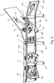
- Movement of the adjustable panels 12 and 13 is effected by means of a powered actuation mechanism comprising a linear actuator 40 and a connecting means in the form of a pivotal "H-frame" 42.
- the H-frame 42 comprises a pair of arms 44 and a cross-member 46 extending between and connecting the arms 44 approximately midway along their length.
- the H-frame is pivotally mounted on the underside of the head end sub-assembly frame 20a at pivot points 48 at the apex of triangular shaped brackets 50 depending from the underside of the frame 20a in the region of hinges 25.
- the arms 44 are generally straight but curve upwards at their distal end where a roller in the form of a bearing 52 is rotatably mounted.
- the bearings 52 contact the underside of the panel 12 along wear resistant strips 54 which may be of metal, nylon or the like, along which the bearings 52 run when the panel 12 is lowered and raised.
- Actuator 40 is a linear actuator of the Delta-drive type as produced by Dewert-Okin GmbH, having a first end (motor and gear box end) pivotally mounted to the cross member 32b and a second end (rod) pivotally connected to a bracket 56 secured to the cross-member 46.
- the bracket 56 is configured such that the connection between the output rod of the actuator and the bracket 56 is in the plane of the panel 12. This is achieved by means of a cut-out slot 58 in the panel 12 through which the bracket 56 and end of the output rod of the actuator extend.
- the gearbox and motor end of the actuator 40 is connected to the cross-member 32b at a position midway along its length.
- the cross-member 32b is located in a plane lower than the general or notional plane of the frame 20 due to the downwardly canted end of the frame 20a.
- the side members 30a are inclined downwards along the final third of their length from a position immediately rearward of the legs 28 attached to the frame 20a.
- the side members are inclined downwards approximately 20 degrees or so, so that the connection point between the actuator 40 and the frame 20a is below and offset from the notional plane of the frame 20. This arrangement ensures the actuator is also inclined with respect to the notional plane of the frame and the plane of the panel 12 when the panel 12 is in its lowered position ( Figures 7 and 8 ).
- the actuator In combination with the other end of the actuator being in the plane of the panel 12, by means of the bracket 56 and cut out 58, the actuator is able to apply a significant initial force to the panel 12 when the panel is to be raised from is lowered position of Figures 7 and 8 . It is to be understood that the force component acting on the panel 12 when movement is initiated from its lowered position is dependent on the angular orientation of the actuator force vector with respect to the panel 12. In arrangements where the actuator 12 is oriented more or less horizontal with respect to the panel significant initial force is required to move the panel and any load supported by the panel from its lowered position due to poor leverage, compared with the arrangement of the illustrated embodiment where the component of the actuator force initially acting on the panel is greater due to its relative inclination to the panel 12.
- Rotational movement of the panel 12 is thus effected by activation of linear electrical actuator 40 positioned on the underside of the bed within the space envelope of the frame.
- panel 12 is raised and lowered by respective extension and retraction of actuator 40.
- the adjustable panels 12 and 13 lie flat on the side rails 30a, with the output rod of actuator 40 fully retracted towards the respective gearbox end of the actuator. This position is shown in Figures 7 and 8 .
- the output rod of the actuator 40 is extended away from the gearbox end of the actuator.
- Rotational movement of mattress bend support panel 13 is thus simultaneously effected by activation of linear electrical actuator 40.
- Panels 12 and 13 are this raised and lowered by extension and retraction of actuator 40.
- the maximum combined angular adjustment of the panels 12 and 13 is 65 degrees, that is to say the maximum raised inclined angle of the backrest panel 12 with respect to the notional flat horizontal plane of the bed is limited to 65 degrees.
- This angle of adjustment includes the combined angle of adjustment of the mattress bend support panel 13 with respect to the fixed panel 14 and the angle of adjustment of the backrest panel 12 with respect to the mattress bend support panel 13.
- the combined angular adjustment may be less, for example, a maximum of 60, 55, 50 degrees or less, and may be contributed by equal amounts of angular adjustment by the panels 13 and 14.
- the maximum angular adjustment is determined by the geometry of the actuation mechanism including the mounting arrangement and the operation stroke of the actuator as well as the relative length dimensions of the respective adjustable panels.
- a mattress of appropriate thickness say in the range of 25-50cm (10-20 inches), is to be positioned on the mattress support platform of the bed 10.
- the frame 20 can be manually folded and unfolded about the traverse hinge axis defined by the hinge elements 24. Either the head end or toe end frame is moved so that the two half sections of the frame are brought together by 10 relative movement about the hinge axis as shown in Figures 9 and 10 where the panels 12 and 14 lie flat on top of the panel 16.
- the adjustable bed 10 has a very small space envelope, with half the length dimension of the unfolded bed in exchange for a modest increase in depth, approximately the additional depth of the toe end half frame.
- the illustrated embodiment thus provides a foldable adjustable bed in which the frame is divided into at least two hinged sections, preferably two sections, more preferably two half sections.
- This assists in storage, transportation, display, delivery and installation.
- An adjustable bed according to the present invention may therefore be more cost effective to ship due to the reduced length dimension of the bed when packaged for shipping, etc.
- up to twice of many beds of the above aspect of the invention could be loaded into an ISO container than conventional non-folding adjustable bed designs, thus reducing transportation and storage costs form the place of manufacture though to delivery to the customer's home.
- An adjustable bed according to the description above may be assembled on site by simply unfolding the sections of the frame and placing a suitable mattress on the unfolded frame.
- a compact package containing the bed may be delivered to a customer's home and readily manoeuvred through standard size doorway and hallway apertures into a room where the bed can be unfolded end to end, to provide a full length frame on which a mattress can be placed.
- This is a significant improvement over hitherto know designs of adjustable beds which typically comprise a kit of parts for assembly at the customer's home. This not only adds to the time of installation, but also requires more skilled labour for delivery and installation.
- references to a mattress include both a separate mattress and a mattress integrated with the support sections or panels.
Landscapes
- Health & Medical Sciences (AREA)
- Nursing (AREA)
- General Health & Medical Sciences (AREA)
- Life Sciences & Earth Sciences (AREA)
- Animal Behavior & Ethology (AREA)
- Public Health (AREA)
- Veterinary Medicine (AREA)
- Invalid Beds And Related Equipment (AREA)
Applications Claiming Priority (2)
| Application Number | Priority Date | Filing Date | Title |
|---|---|---|---|
| GBGB1610212.1A GB201610212D0 (en) | 2016-06-13 | 2016-06-13 | Adjustable bed |
| PCT/GB2017/051722 WO2017216547A1 (en) | 2016-06-13 | 2017-06-13 | Adjustable bed |
Publications (2)
| Publication Number | Publication Date |
|---|---|
| EP3468418A1 EP3468418A1 (en) | 2019-04-17 |
| EP3468418B1 true EP3468418B1 (en) | 2020-09-30 |
Family
ID=56894677
Family Applications (1)
| Application Number | Title | Priority Date | Filing Date |
|---|---|---|---|
| EP17732159.3A Active EP3468418B1 (en) | 2016-06-13 | 2017-06-13 | Adjustable bed |
Country Status (8)
| Country | Link |
|---|---|
| US (1) | US11812857B2 (enExample) |
| EP (1) | EP3468418B1 (enExample) |
| JP (1) | JP7012669B2 (enExample) |
| CN (2) | CN109310214A (enExample) |
| CA (1) | CA3026473C (enExample) |
| ES (1) | ES2833224T3 (enExample) |
| GB (2) | GB201610212D0 (enExample) |
| WO (1) | WO2017216547A1 (enExample) |
Cited By (1)
| Publication number | Priority date | Publication date | Assignee | Title |
|---|---|---|---|---|
| US11812857B2 (en) | 2016-06-13 | 2023-11-14 | Motus Mechanics Limited | Adjustable furniture |
Families Citing this family (18)
| Publication number | Priority date | Publication date | Assignee | Title |
|---|---|---|---|---|
| GB201712186D0 (en) * | 2017-07-28 | 2017-09-13 | Motus Mech Ltd | Adjustable furniture |
| TWM553151U (zh) * | 2017-07-24 | 2017-12-21 | Quan Hang Shi | 電動床 |
| DE102018126696A1 (de) | 2018-08-06 | 2020-02-06 | Logicdata Electronic & Software Entwicklungs Gmbh | Verpackungsanordnung und Verfahren zum Verpacken |
| CN109126057A (zh) * | 2018-09-14 | 2019-01-04 | 济宁市兖州区阅木家具有限公司 | 一种可调节式健身智能床椅 |
| US20200221882A1 (en) * | 2019-01-10 | 2020-07-16 | Nisco Co., Ltd | Adjustable bed system having fans |
| US11766132B2 (en) * | 2019-06-18 | 2023-09-26 | Nisco (Thailand) Co., Ltd | Adjustable bed with tilting mechanisms |
| CN113261809A (zh) * | 2020-02-14 | 2021-08-17 | 嘉兴赛诺机械有限公司 | 一种可折叠的床 |
| CN112273923A (zh) * | 2019-07-24 | 2021-01-29 | 嘉兴赛诺机械有限公司 | 具有多个床部分的床 |
| CN112386047A (zh) * | 2019-08-15 | 2021-02-23 | 麒盛科技股份有限公司 | 一种三折叠电动床 |
| WO2021176476A1 (en) * | 2020-03-04 | 2021-09-10 | M/S. Lifeline Pharma | A bed comprising a foldable board and a foldable mattress |
| CN212139978U (zh) * | 2020-03-11 | 2020-12-15 | 锐迈机械科技(吴江)有限公司 | 一种折叠床用连杆组件及折叠床 |
| WO2022093296A1 (en) * | 2020-10-31 | 2022-05-05 | Guenther Gregg M | Stretching machine |
| US12022954B2 (en) * | 2021-02-11 | 2024-07-02 | Motomotion China Corporation | Ready to assemble structural system for a bed |
| CN214803667U (zh) * | 2021-05-17 | 2021-11-23 | 杭州大乘影视传媒有限公司 | 一种电动床架 |
| CN113975009B (zh) * | 2021-11-15 | 2022-09-23 | 开封市中心医院 | 一种神经内科卧床患者护理用的翻身辅助装置 |
| US20230165381A1 (en) * | 2021-12-01 | 2023-06-01 | Ergomotion, Inc. | Modular pneumatic actuation system for head tilt and lumbar supports in an adjustable bed |
| TWI803397B (zh) * | 2022-07-21 | 2023-05-21 | 施權航 | 電動床 |
| GB202311637D0 (en) | 2023-07-28 | 2023-09-13 | Eevolv Ltd | A bed |
Citations (1)
| Publication number | Priority date | Publication date | Assignee | Title |
|---|---|---|---|---|
| WO2017147094A1 (en) * | 2016-02-24 | 2017-08-31 | Dreamwell, Ltd. | Adjustable foundation |
Family Cites Families (144)
| Publication number | Priority date | Publication date | Assignee | Title |
|---|---|---|---|---|
| US139493A (en) | 1873-06-03 | Improvement in invalid-bedsteads | ||
| US638466A (en) | 1899-09-30 | 1899-12-05 | J A Kelly & Bros Inc | Sofa-bedstead. |
| US912214A (en) | 1908-07-18 | 1909-02-09 | Lloyd W Ward | Invalid-bed. |
| GB191322022A (en) | 1913-09-30 | 1914-08-20 | Albert Tyzack | Improvements in or connected with Reclining Chairs having Adjustable Seats and Backs. |
| GB101239A (en) | 1916-02-15 | 1916-08-31 | Albert Glenister | Improvements in or relating to Chairs, Couches or the like. |
| US1238078A (en) | 1916-06-06 | 1917-08-28 | Harvey N Ault | Adjustable chair. |
| GB173772A (en) | 1921-01-04 | 1922-12-14 | Albert Edwin Gell | Improvements in reclining adjustable chairs and seats |
| GB329834A (en) | 1929-05-17 | 1930-05-29 | Abraham Hart | Improvements in or relating to chairs, seats and the like |
| GB414464A (en) | 1933-03-28 | 1934-08-09 | H J Searle & Son Ltd | Improvements in and relating to adjustable chairs and settees |
| US2497395A (en) | 1946-03-04 | 1950-02-14 | Sr Roy A Cramer | Reclining chair |
| GB775679A (en) | 1954-06-15 | 1957-05-29 | Greaves & Thomas Ltd | Improvements in and relating to reclining chairs |
| US2954072A (en) | 1956-07-17 | 1960-09-27 | Fossati Mario | Hinged rods mechanism for reclinable armchairs |
| US2859797A (en) | 1957-12-31 | 1958-11-11 | James W Mitchelson | Adjustable reclining chair and headrest therefor |
| DE1229403B (de) | 1959-01-31 | 1966-11-24 | Recaro G M B H & Co | Gelenkbeschlag fuer Kraftfahrzeugsitze |
| US3086814A (en) | 1959-06-15 | 1963-04-23 | Anton Lorenz | Reclining chair of the multiple movement type |
| DE1404651C3 (de) | 1959-09-17 | 1975-07-24 | Fridtjof F. 1000 Berlin Schliephacke | Verstellsessel mit ausschwenkbarer Beinstütze |
| US3281141A (en) | 1963-01-15 | 1966-10-25 | American Sterilizer Co | Surgical table |
| US3202453A (en) | 1963-07-09 | 1965-08-24 | Ford Motor Co | Retractable seat |
| US3369767A (en) | 1965-09-27 | 1968-02-20 | Greenfield Company | Seat belt retractor |
| CA851402A (en) | 1968-06-22 | 1970-09-15 | Royalmetal Corporation Limited | Hospital bed |
| US3797050A (en) | 1972-08-10 | 1974-03-19 | Interroyal Corp | Shock and drainage mechanism |
| US3847430A (en) | 1972-10-20 | 1974-11-12 | P Fletcher | Reclining chair with movable headrest |
| US3873152A (en) | 1974-01-09 | 1975-03-25 | John Garas | Adjustable orthopedic lounger |
| CH597799A5 (en) | 1975-10-02 | 1978-04-14 | Maurice Bourda | Articulating sub-frame for reclining bed |
| US4202062A (en) | 1978-07-10 | 1980-05-13 | Marcy Tool Company | Knock-down invalid bed |
| US4212495A (en) | 1979-01-26 | 1980-07-15 | Sears, Roebuck & Co. | Reclining chair |
| US4332417A (en) | 1979-12-06 | 1982-06-01 | Hoover Universal, Inc. | Reclining actuator for a recliner chair |
| GB2085719B (en) | 1980-08-20 | 1984-04-11 | Antocks Lairn Ltd | Adjustable chairs |
| FR2527061B1 (fr) | 1982-05-19 | 1985-11-15 | Ami | Siege articule |
| EP0107882B1 (en) | 1982-10-28 | 1986-07-23 | FLIGHT EQUIPMENT & ENGINEERING LIMITED | Vehicle seats |
| JPH01214308A (ja) | 1988-02-23 | 1989-08-28 | Kunimatsu Kogyo Kk | リクライニング式シート |
| JPH0289947U (enExample) | 1988-12-28 | 1990-07-17 | ||
| DE3903874C2 (de) | 1989-02-10 | 1994-10-06 | Vauth Sagel Gmbh & Co | Verstellbares Kranken- und Pflegebett |
| US4996731A (en) | 1989-04-19 | 1991-03-05 | Kruyt Robert A | Adjustable bed |
| US5246266A (en) | 1990-09-18 | 1993-09-21 | Chairworks Taiwan Limited | Chair |
| CA2045308A1 (en) * | 1991-06-24 | 1992-12-25 | Timothy Carroll | Hospital bed particularly for home care |
| EP0641534B1 (en) * | 1993-09-08 | 1998-12-16 | Paramount Bed Company Limited | A bed base structure |
| US5625913A (en) | 1994-02-14 | 1997-05-06 | Singleton; William H. | Oscillatory bed |
| NO300754B1 (no) | 1994-10-14 | 1997-07-21 | Handicare Ind As | Anordning ved stillbar stol |
| GB9425078D0 (en) | 1994-12-13 | 1995-02-08 | British Airways Plc | A seating unit |
| JP3605161B2 (ja) | 1994-12-21 | 2004-12-22 | シロキ工業株式会社 | リクライニング装置 |
| DE19508907C1 (de) * | 1995-03-11 | 1996-10-02 | Dewert Antriebs Systemtech | Schwenkbeschlag für eine Rücken- und Kopfstütze eines Matratzenrahmens |
| WO1996029970A1 (en) | 1995-03-27 | 1996-10-03 | Scandinavian Mobility Ec-Høng A/S | A bed |
| US5640730A (en) * | 1995-05-11 | 1997-06-24 | Maxwell Products, Inc. | Adjustable articulated bed with tiltable head portion |
| JPH08308680A (ja) | 1995-05-17 | 1996-11-26 | Tenryu Ind Co Ltd | 乗物用座席のレグレスト |
| SE510584C2 (sv) * | 1995-08-17 | 1999-06-07 | Eneryda Vaardprodukter I Enery | Säng |
| JP3352320B2 (ja) * | 1995-11-10 | 2002-12-03 | フランスベッド株式会社 | 起床式ベッド装置 |
| JP3343472B2 (ja) | 1995-11-10 | 2002-11-11 | フランスベッド株式会社 | ベッド装置 |
| FR2740953B1 (fr) | 1995-11-14 | 1998-01-23 | Oniris Sa | Sommier deformable a profil ergonomique |
| US5669090A (en) | 1995-12-22 | 1997-09-23 | Basgall; Dale G. | Rehabilitation bed transformable to multiple positions for accommodating an obese person |
| IT1282278B1 (it) | 1995-12-29 | 1998-03-16 | Bortoluzzi Mobili Srl | Letto con piano d'appoggio a sezioni reclinabili mediante un meccanismo semiautomatico ad azionamento manuale |
| DE19711944C2 (de) | 1997-03-21 | 2000-08-31 | Girsberger Holding Ag Buetzber | Fahrzeugsitz |
| US5897462A (en) | 1997-04-18 | 1999-04-27 | St. Germain; Robert J. | Exercise apparatus |
| DE29715343U1 (de) | 1997-08-27 | 1997-11-27 | Unimet Zentrallager Nord GmbH & Co. KG, 28876 Oyten | Sitzmöbel, insbesondere Gartensessel |
| JPH11244096A (ja) | 1998-03-06 | 1999-09-14 | Tsunayoshi Morikawa | 腰スライド機構を有するリクライニングベッド |
| US6101648A (en) | 1998-04-22 | 2000-08-15 | Sunrise Medical Ccg Inc. | Ramp assembly for an articulating bed |
| FR2780256B1 (fr) * | 1998-06-24 | 2000-08-25 | Epeda Sa | Sommier de lit reglable |
| DE19906547B4 (de) | 1999-02-17 | 2004-03-25 | Innovint Einrichtungs Gmbh | Kindersitz zur mobilen Verwendung in einem Flugzeug |
| DE19908084C1 (de) | 1999-02-25 | 2000-05-11 | Recticel Int Bettsysteme Gmbh | Verstellvorrichtung für einen Sitz oder eine Liege, insbesondere für ein Bett |
| JP2001095858A (ja) * | 1999-03-25 | 2001-04-10 | Matsushita Seiko Co Ltd | 身体を動作させる装置 |
| IT1306152B1 (it) | 1999-06-02 | 2001-05-30 | Aviointeriors Spa | Poltrona con movimento a culla perfezionato, in particolare peraeromobili. |
| DE19962541C3 (de) | 1999-12-23 | 2003-11-27 | Ag Goldingen Cimosys | Motorisch verstellbare Stützeinrichtung für eine Polsterung eines Sitz- und/oder Liegemöbels, beispielsweise einer Matratze oder eines Bettes |
| FR2803500B1 (fr) | 2000-01-06 | 2002-04-26 | Oniris Sa | Plan de couchage d'un sommier deformable |
| GB2362566B (en) | 2000-05-27 | 2002-07-17 | Huntleigh Technology Plc | Adjustable platform |
| JP3518741B2 (ja) * | 2000-06-14 | 2004-04-12 | パラマウントベッド株式会社 | ベッドの湾曲ボトム |
| AU9137401A (en) | 2000-11-18 | 2002-05-23 | Moon Ho Choi | Safety device for car seat |
| GB0101239D0 (en) | 2001-01-17 | 2001-02-28 | 3M Innovative Properties Co | Medicinal aerosols |
| JP2003199641A (ja) | 2001-01-25 | 2003-07-15 | Hirobumi Tada | リクライニング装置 |
| AU2002248713A1 (en) | 2001-03-27 | 2002-10-08 | Hill-Rom Services, Inc. | Hospital bed |
| US20020144350A1 (en) * | 2001-04-09 | 2002-10-10 | Shih Long Time | Electric folding bed having adjustable bed frames |
| EP2289734B2 (en) | 2001-08-09 | 2018-07-04 | Virgin Atlantic Airways Limited | A seating system and a passenger seat unit for an aircraft |
| JP4902070B2 (ja) | 2001-08-22 | 2012-03-21 | コンビ株式会社 | チャイルドシート |
| DE20113953U1 (de) * | 2001-08-23 | 2001-10-18 | Recticel Schlafkomfort GmbH, 59439 Holzwickede | Hubbeschlag für motorisch verstellbaren Bettrahmen |
| DE10152227C2 (de) | 2001-10-20 | 2003-10-09 | Sichelschmidt Stanzwerk | Sitzmöbel |
| ES2212873B1 (es) | 2001-10-24 | 2005-11-16 | Leonor Porrata Bonnin | Armazon para sofas. |
| US20030172455A1 (en) | 2002-03-18 | 2003-09-18 | Roma John K. | Spring-assisted futon frame |
| JP2004016558A (ja) * | 2002-06-18 | 2004-01-22 | France Bed Co Ltd | 起床式ベッド装置 |
| JP2004016635A (ja) * | 2002-06-19 | 2004-01-22 | Paramount Bed Co Ltd | ベッド等における背・膝ボトム連動動作機構 |
| DE20217698U1 (de) | 2002-07-10 | 2004-04-01 | Cimosys Ag | Verstellvorrichtung für Betten, Matratzen, Sessel u.dgl. |
| US6739661B1 (en) | 2002-07-15 | 2004-05-25 | David N. Dukes | Pivotable reclining child safety car seat |
| TWI278296B (en) * | 2002-07-24 | 2007-04-11 | France Bed Co | Bed apparatus and mattress |
| DE10261645A1 (de) | 2002-12-27 | 2004-07-22 | Fried-Jan Unger | Verstellbare Liege oder Bett |
| US7036165B2 (en) * | 2003-04-02 | 2006-05-02 | L&P Property Management Company | Adjustable bed with automatic adjusting head section |
| DE20308723U1 (de) | 2003-06-04 | 2003-08-07 | Arnold, Günter, 24977 Langballig | Stuhl |
| GB0325358D0 (en) | 2003-10-30 | 2003-12-03 | Peter Cook Internat Plc | Powered furniture |
| FR2862850B1 (fr) | 2003-12-01 | 2006-01-27 | Holding B Marly Sa | Ensemble de relaxation pour l'ameublement ou l'automobile, du type canape, fauteuil ou siege transformable, pouvant fonctionner en etant positionne directement contre une paroi |
| GB2409607A (en) | 2003-12-23 | 2005-06-29 | Symbian Ltd | Caller ID using a movie clip |
| US7237289B2 (en) | 2004-03-23 | 2007-07-03 | Invacare Corporation | Platform for adjustable height bed |
| WO2005103929A1 (en) | 2004-04-20 | 2005-11-03 | Pluck Corporation | Method, system, and computer program product for sharing information within a global computer network |
| WO2005107533A1 (en) | 2004-05-07 | 2005-11-17 | Ramachandra Rao Gudipati | Support for baby |
| GB2415759B (en) | 2004-06-29 | 2007-06-13 | Newfrey Llc | A threaded insert |
| EP1621175B1 (en) | 2004-07-30 | 2012-06-13 | Hill-Rom Services, Inc. | Bed having a chair egress position |
| AU2005277594A1 (en) | 2004-08-16 | 2006-03-02 | Hill-Rom Services, Inc. | Chair |
| CN2724673Y (zh) * | 2004-09-06 | 2005-09-14 | 乔军 | 自动感应病床 |
| GB0422205D0 (en) | 2004-10-07 | 2004-11-03 | Arthurs Alfred W | Chair incorporating mechanism to assist rising |
| ES2300731T3 (es) * | 2004-12-28 | 2008-06-16 | Industrias Hidraulicas Pardo, S.A. | Mecanismo de acomodacion posicional para camas. |
| DE102005016943B4 (de) | 2005-04-12 | 2006-11-30 | Stanzwerk Wetter Sichelschmidt Gmbh & Co. Kg | Ottomane |
| DE202005015275U1 (de) | 2005-09-28 | 2005-12-08 | himolla Polstermöbel GmbH | Sitz-/Liegemöbel |
| CA2630111C (en) | 2005-11-21 | 2015-02-10 | Nightgear Llc | Seating accessory |
| US7585018B2 (en) | 2006-01-10 | 2009-09-08 | La-Z-Boy Incorporated | Wall proximity reclining chair with in-line linkage mechanism |
| US7455360B2 (en) | 2006-04-21 | 2008-11-25 | L & P Property Management | Seating furniture with lift mechanism |
| US7703851B2 (en) | 2006-09-21 | 2010-04-27 | Mazda Motor Corporation | Seat device |
| US7445279B2 (en) | 2006-11-13 | 2008-11-04 | L & P Property Management Company | Pivot-over-arm reclining mechanism for a seating unit |
| US7766421B2 (en) | 2006-12-21 | 2010-08-03 | L & P Property Management Company | Recliner lift chair with power lift and reclining units |
| FR2911485B1 (fr) * | 2007-01-19 | 2010-10-15 | Le Bed | Structure de couchage articulee |
| GB0704546D0 (en) | 2007-03-08 | 2007-04-18 | Contour Premium Aircraft Seati | Adjustable seat |
| WO2008129566A1 (en) | 2007-04-18 | 2008-10-30 | Stema S.R.L. | Mechanism for reclining armchairs or sofas |
| US7862110B2 (en) | 2007-04-20 | 2011-01-04 | L & P Property Management Company | Headrest for recliner chair |
| GB0708053D0 (en) | 2007-04-26 | 2007-06-06 | Leuven | Adjustable furniture |
| DE102007024218A1 (de) | 2007-05-11 | 2008-11-13 | Appeltshauser, Georg, Dipl.-Ing. | Sitzmöbel |
| DE202007009068U1 (de) | 2007-06-28 | 2007-11-15 | Biniaminov, Youri | Die Mechanik des Aufstiegs des Sitzes |
| US7913336B2 (en) | 2007-08-14 | 2011-03-29 | Stryker Corporation | Shearless pivot for bed |
| ES2352391B8 (es) | 2007-10-12 | 2012-05-21 | Stanzwerk Wetter Sichelschmidt Gmbh & Co. Kg | Mueble de asiento. |
| US7641277B2 (en) | 2008-01-02 | 2010-01-05 | L & P Property Management Co. | Zero-wall clearance linkage mechanism for a high-leg seating unit |
| US20090178201A1 (en) * | 2008-01-15 | 2009-07-16 | L&P Property Management Company | Adjustable Bed Having Movable Lumbar Support |
| JP5763639B2 (ja) | 2009-08-18 | 2015-08-12 | インテグレイテッド ファーニチャー テクノロジーズ リミテッドIntegrated Furniture Technologies Limited | 調整可能な家具 |
| GB0918685D0 (en) | 2009-10-23 | 2009-12-09 | Integrated Furniture Technolog | Adjustable furniture |
| US8226162B2 (en) | 2009-09-11 | 2012-07-24 | Campbell Corey A | Child safety seat |
| US20120240337A1 (en) | 2009-10-28 | 2012-09-27 | Ruoey Lung Enterprise Corp. | Two-stage actuating device for electric apparatus |
| DE102010014126B4 (de) | 2010-04-07 | 2011-11-10 | Ferdinand Lusch Gmbh & Co. Kg | Sitzmöbel mit einem in eine Aufstehhilfesposition schwenkbaren Sitz |
| CN201668626U (zh) * | 2010-05-05 | 2010-12-15 | 曹树汉 | 电动升降床 |
| US8403415B2 (en) | 2010-08-16 | 2013-03-26 | Be Aerospace, Inc. | Aircraft passenger seat recline mechanism |
| US10004334B2 (en) | 2010-09-09 | 2018-06-26 | Integrated Furniture Technologies Limited | Lift-recliner chair |
| GB201015084D0 (en) | 2010-09-09 | 2010-10-27 | Integrated Furniture Technologies Ltd | Lift-recliner chair |
| US8534758B2 (en) | 2010-09-13 | 2013-09-17 | Tropitone Furniture Co., Inc. | Reclinable seating apparatus and method |
| JP5634891B2 (ja) | 2011-01-17 | 2014-12-03 | カリモク家具株式会社 | 椅子 |
| NO335055B1 (no) | 2011-05-16 | 2014-09-01 | Sapdesign As | Anordning ved stol |
| EP2717742B1 (en) | 2011-06-09 | 2015-12-16 | Haworth, Inc | Forward sliding reclining chair |
| ITRM20110166U1 (it) | 2011-10-26 | 2013-04-27 | Natuzzi Spa | Struttura di dispositivo per la movimentazione di componenti di appoggio di un divano, una poltrona o simili |
| CN202314169U (zh) | 2011-10-31 | 2012-07-11 | 珠海西格医疗设备有限公司 | 背俯仰组件及座椅 |
| ITPN20120022A1 (it) * | 2012-04-27 | 2013-10-28 | C M Sogni S A S Di Collodel A & C | Supporto ergonomico di sostegno di persone di tipo regolabile in altezza, per adattarlo alle diverse forme della schiena delle persone e determinare il sostegno delle persone stesse con un effetto massaggiante |
| US20140041121A1 (en) | 2012-08-07 | 2014-02-13 | Jiaxing Shufude Electric Bed Co., Ltd | Lumbar Folding Bed |
| CN103142059B (zh) * | 2013-03-18 | 2015-09-16 | 常州市锐新医疗器械有限公司 | 超低家用多功能电动床 |
| KR20160002917A (ko) * | 2013-04-18 | 2016-01-08 | 파라마운트 베드 가부시키가이샤 | 침대 장치의 보텀 |
| EP2994019B1 (en) | 2013-05-10 | 2018-04-25 | L&P Property Management Company | Linkage mechanism for high-leg seating unit |
| GB2516437A (en) | 2013-07-20 | 2015-01-28 | Integrated Furniture Technologies Ltd | Adjustable furniture |
| GB2520253A (en) | 2013-11-12 | 2015-05-20 | Integrated Furniture Technologies Ltd | Adjustable bed |
| CN203538846U (zh) | 2013-11-29 | 2014-04-16 | 宁波市鄞州康福特家具有限公司 | 电动睡姿调节床 |
| CN107087394B (zh) * | 2014-10-14 | 2019-08-02 | 马尔韦斯蒂奥股份公司 | 用于住院的床 |
| GB201610212D0 (en) | 2016-06-13 | 2016-07-27 | Motus Mech Ltd | Adjustable bed |
| GB201504140D0 (en) | 2015-03-11 | 2015-04-22 | Motus Mechanics Ltd | Adjustable bed |
| US20200154899A1 (en) | 2015-03-11 | 2020-05-21 | Motus Mechanics Ltd. | Adjustable furniture |
| US20200154888A1 (en) | 2015-03-11 | 2020-05-21 | Motus Mechanics Ltd. | Adjustable furniture |
| CN105326256A (zh) * | 2015-11-26 | 2016-02-17 | 常州裕丰家具有限公司 | 可调节功能床 |
-
2016
- 2016-06-13 GB GBGB1610212.1A patent/GB201610212D0/en not_active Ceased
-
2017
- 2017-06-13 CN CN201780036988.9A patent/CN109310214A/zh active Pending
- 2017-06-13 WO PCT/GB2017/051722 patent/WO2017216547A1/en not_active Ceased
- 2017-06-13 JP JP2018566248A patent/JP7012669B2/ja active Active
- 2017-06-13 US US16/307,530 patent/US11812857B2/en active Active
- 2017-06-13 ES ES17732159T patent/ES2833224T3/es active Active
- 2017-06-13 CA CA3026473A patent/CA3026473C/en active Active
- 2017-06-13 GB GB1709407.9A patent/GB2552886A/en not_active Withdrawn
- 2017-06-13 EP EP17732159.3A patent/EP3468418B1/en active Active
- 2017-06-13 CN CN202411665932.8A patent/CN119498648A/zh active Pending
Patent Citations (1)
| Publication number | Priority date | Publication date | Assignee | Title |
|---|---|---|---|---|
| WO2017147094A1 (en) * | 2016-02-24 | 2017-08-31 | Dreamwell, Ltd. | Adjustable foundation |
Cited By (1)
| Publication number | Priority date | Publication date | Assignee | Title |
|---|---|---|---|---|
| US11812857B2 (en) | 2016-06-13 | 2023-11-14 | Motus Mechanics Limited | Adjustable furniture |
Also Published As
| Publication number | Publication date |
|---|---|
| US11812857B2 (en) | 2023-11-14 |
| CN119498648A (zh) | 2025-02-25 |
| EP3468418A1 (en) | 2019-04-17 |
| CA3026473C (en) | 2023-12-05 |
| JP7012669B2 (ja) | 2022-02-14 |
| JP2019521758A (ja) | 2019-08-08 |
| US20190142177A1 (en) | 2019-05-16 |
| ES2833224T3 (es) | 2021-06-14 |
| GB201610212D0 (en) | 2016-07-27 |
| CA3026473A1 (en) | 2017-12-21 |
| WO2017216547A1 (en) | 2017-12-21 |
| GB2552886A (en) | 2018-02-14 |
| GB201709407D0 (en) | 2017-07-26 |
| CN109310214A (zh) | 2019-02-05 |
Similar Documents
| Publication | Publication Date | Title |
|---|---|---|
| EP3468418B1 (en) | Adjustable bed | |
| US10306994B2 (en) | Adjustable furniture | |
| US20200154899A1 (en) | Adjustable furniture | |
| US20200154888A1 (en) | Adjustable furniture | |
| EP3046444B1 (en) | Adjustable bed | |
| EP3267845B1 (en) | Adjustable bed | |
| CA3071459A1 (en) | Adjustable furniture | |
| WO2016102519A1 (en) | Adjustable furniture |
Legal Events
| Date | Code | Title | Description |
|---|---|---|---|
| STAA | Information on the status of an ep patent application or granted ep patent |
Free format text: STATUS: UNKNOWN |
|
| STAA | Information on the status of an ep patent application or granted ep patent |
Free format text: STATUS: THE INTERNATIONAL PUBLICATION HAS BEEN MADE |
|
| PUAI | Public reference made under article 153(3) epc to a published international application that has entered the european phase |
Free format text: ORIGINAL CODE: 0009012 |
|
| STAA | Information on the status of an ep patent application or granted ep patent |
Free format text: STATUS: REQUEST FOR EXAMINATION WAS MADE |
|
| 17P | Request for examination filed |
Effective date: 20190104 |
|
| AK | Designated contracting states |
Kind code of ref document: A1 Designated state(s): AL AT BE BG CH CY CZ DE DK EE ES FI FR GB GR HR HU IE IS IT LI LT LU LV MC MK MT NL NO PL PT RO RS SE SI SK SM TR |
|
| AX | Request for extension of the european patent |
Extension state: BA ME |
|
| DAV | Request for validation of the european patent (deleted) | ||
| DAX | Request for extension of the european patent (deleted) | ||
| STAA | Information on the status of an ep patent application or granted ep patent |
Free format text: STATUS: EXAMINATION IS IN PROGRESS |
|
| 17Q | First examination report despatched |
Effective date: 20191022 |
|
| GRAP | Despatch of communication of intention to grant a patent |
Free format text: ORIGINAL CODE: EPIDOSNIGR1 |
|
| STAA | Information on the status of an ep patent application or granted ep patent |
Free format text: STATUS: GRANT OF PATENT IS INTENDED |
|
| INTG | Intention to grant announced |
Effective date: 20200428 |
|
| GRAS | Grant fee paid |
Free format text: ORIGINAL CODE: EPIDOSNIGR3 |
|
| GRAA | (expected) grant |
Free format text: ORIGINAL CODE: 0009210 |
|
| STAA | Information on the status of an ep patent application or granted ep patent |
Free format text: STATUS: THE PATENT HAS BEEN GRANTED |
|
| AK | Designated contracting states |
Kind code of ref document: B1 Designated state(s): AL AT BE BG CH CY CZ DE DK EE ES FI FR GB GR HR HU IE IS IT LI LT LU LV MC MK MT NL NO PL PT RO RS SE SI SK SM TR |
|
| REG | Reference to a national code |
Ref country code: CH Ref legal event code: EP Ref country code: GB Ref legal event code: FG4D |
|
| REG | Reference to a national code |
Ref country code: AT Ref legal event code: REF Ref document number: 1317870 Country of ref document: AT Kind code of ref document: T Effective date: 20201015 |
|
| REG | Reference to a national code |
Ref country code: DE Ref legal event code: R096 Ref document number: 602017024593 Country of ref document: DE |
|
| REG | Reference to a national code |
Ref country code: IE Ref legal event code: FG4D |
|
| REG | Reference to a national code |
Ref country code: SE Ref legal event code: TRGR |
|
| REG | Reference to a national code |
Ref country code: NL Ref legal event code: FP |
|
| REG | Reference to a national code |
Ref country code: NO Ref legal event code: T2 Effective date: 20200930 |
|
| PG25 | Lapsed in a contracting state [announced via postgrant information from national office to epo] |
Ref country code: GR Free format text: LAPSE BECAUSE OF FAILURE TO SUBMIT A TRANSLATION OF THE DESCRIPTION OR TO PAY THE FEE WITHIN THE PRESCRIBED TIME-LIMIT Effective date: 20201231 Ref country code: BG Free format text: LAPSE BECAUSE OF FAILURE TO SUBMIT A TRANSLATION OF THE DESCRIPTION OR TO PAY THE FEE WITHIN THE PRESCRIBED TIME-LIMIT Effective date: 20201230 Ref country code: FI Free format text: LAPSE BECAUSE OF FAILURE TO SUBMIT A TRANSLATION OF THE DESCRIPTION OR TO PAY THE FEE WITHIN THE PRESCRIBED TIME-LIMIT Effective date: 20200930 Ref country code: HR Free format text: LAPSE BECAUSE OF FAILURE TO SUBMIT A TRANSLATION OF THE DESCRIPTION OR TO PAY THE FEE WITHIN THE PRESCRIBED TIME-LIMIT Effective date: 20200930 |
|
| REG | Reference to a national code |
Ref country code: AT Ref legal event code: MK05 Ref document number: 1317870 Country of ref document: AT Kind code of ref document: T Effective date: 20200930 |
|
| PG25 | Lapsed in a contracting state [announced via postgrant information from national office to epo] |
Ref country code: LV Free format text: LAPSE BECAUSE OF FAILURE TO SUBMIT A TRANSLATION OF THE DESCRIPTION OR TO PAY THE FEE WITHIN THE PRESCRIBED TIME-LIMIT Effective date: 20200930 Ref country code: RS Free format text: LAPSE BECAUSE OF FAILURE TO SUBMIT A TRANSLATION OF THE DESCRIPTION OR TO PAY THE FEE WITHIN THE PRESCRIBED TIME-LIMIT Effective date: 20200930 |
|
| REG | Reference to a national code |
Ref country code: LT Ref legal event code: MG4D |
|
| PG25 | Lapsed in a contracting state [announced via postgrant information from national office to epo] |
Ref country code: SM Free format text: LAPSE BECAUSE OF FAILURE TO SUBMIT A TRANSLATION OF THE DESCRIPTION OR TO PAY THE FEE WITHIN THE PRESCRIBED TIME-LIMIT Effective date: 20200930 Ref country code: EE Free format text: LAPSE BECAUSE OF FAILURE TO SUBMIT A TRANSLATION OF THE DESCRIPTION OR TO PAY THE FEE WITHIN THE PRESCRIBED TIME-LIMIT Effective date: 20200930 Ref country code: CZ Free format text: LAPSE BECAUSE OF FAILURE TO SUBMIT A TRANSLATION OF THE DESCRIPTION OR TO PAY THE FEE WITHIN THE PRESCRIBED TIME-LIMIT Effective date: 20200930 Ref country code: PT Free format text: LAPSE BECAUSE OF FAILURE TO SUBMIT A TRANSLATION OF THE DESCRIPTION OR TO PAY THE FEE WITHIN THE PRESCRIBED TIME-LIMIT Effective date: 20210201 Ref country code: RO Free format text: LAPSE BECAUSE OF FAILURE TO SUBMIT A TRANSLATION OF THE DESCRIPTION OR TO PAY THE FEE WITHIN THE PRESCRIBED TIME-LIMIT Effective date: 20200930 Ref country code: LT Free format text: LAPSE BECAUSE OF FAILURE TO SUBMIT A TRANSLATION OF THE DESCRIPTION OR TO PAY THE FEE WITHIN THE PRESCRIBED TIME-LIMIT Effective date: 20200930 |
|
| PG25 | Lapsed in a contracting state [announced via postgrant information from national office to epo] |
Ref country code: AT Free format text: LAPSE BECAUSE OF FAILURE TO SUBMIT A TRANSLATION OF THE DESCRIPTION OR TO PAY THE FEE WITHIN THE PRESCRIBED TIME-LIMIT Effective date: 20200930 Ref country code: AL Free format text: LAPSE BECAUSE OF FAILURE TO SUBMIT A TRANSLATION OF THE DESCRIPTION OR TO PAY THE FEE WITHIN THE PRESCRIBED TIME-LIMIT Effective date: 20200930 Ref country code: IS Free format text: LAPSE BECAUSE OF FAILURE TO SUBMIT A TRANSLATION OF THE DESCRIPTION OR TO PAY THE FEE WITHIN THE PRESCRIBED TIME-LIMIT Effective date: 20210130 Ref country code: PL Free format text: LAPSE BECAUSE OF FAILURE TO SUBMIT A TRANSLATION OF THE DESCRIPTION OR TO PAY THE FEE WITHIN THE PRESCRIBED TIME-LIMIT Effective date: 20200930 |
|
| REG | Reference to a national code |
Ref country code: ES Ref legal event code: FG2A Ref document number: 2833224 Country of ref document: ES Kind code of ref document: T3 Effective date: 20210614 |
|
| PG25 | Lapsed in a contracting state [announced via postgrant information from national office to epo] |
Ref country code: SK Free format text: LAPSE BECAUSE OF FAILURE TO SUBMIT A TRANSLATION OF THE DESCRIPTION OR TO PAY THE FEE WITHIN THE PRESCRIBED TIME-LIMIT Effective date: 20200930 |
|
| REG | Reference to a national code |
Ref country code: DE Ref legal event code: R097 Ref document number: 602017024593 Country of ref document: DE |
|
| PLBE | No opposition filed within time limit |
Free format text: ORIGINAL CODE: 0009261 |
|
| STAA | Information on the status of an ep patent application or granted ep patent |
Free format text: STATUS: NO OPPOSITION FILED WITHIN TIME LIMIT |
|
| PG25 | Lapsed in a contracting state [announced via postgrant information from national office to epo] |
Ref country code: DK Free format text: LAPSE BECAUSE OF FAILURE TO SUBMIT A TRANSLATION OF THE DESCRIPTION OR TO PAY THE FEE WITHIN THE PRESCRIBED TIME-LIMIT Effective date: 20200930 |
|
| 26N | No opposition filed |
Effective date: 20210701 |
|
| PG25 | Lapsed in a contracting state [announced via postgrant information from national office to epo] |
Ref country code: SI Free format text: LAPSE BECAUSE OF FAILURE TO SUBMIT A TRANSLATION OF THE DESCRIPTION OR TO PAY THE FEE WITHIN THE PRESCRIBED TIME-LIMIT Effective date: 20200930 |
|
| PG25 | Lapsed in a contracting state [announced via postgrant information from national office to epo] |
Ref country code: MC Free format text: LAPSE BECAUSE OF FAILURE TO SUBMIT A TRANSLATION OF THE DESCRIPTION OR TO PAY THE FEE WITHIN THE PRESCRIBED TIME-LIMIT Effective date: 20200930 |
|
| REG | Reference to a national code |
Ref country code: CH Ref legal event code: PL |
|
| PG25 | Lapsed in a contracting state [announced via postgrant information from national office to epo] |
Ref country code: LU Free format text: LAPSE BECAUSE OF NON-PAYMENT OF DUE FEES Effective date: 20210613 |
|
| PG25 | Lapsed in a contracting state [announced via postgrant information from national office to epo] |
Ref country code: LI Free format text: LAPSE BECAUSE OF NON-PAYMENT OF DUE FEES Effective date: 20210630 Ref country code: IE Free format text: LAPSE BECAUSE OF NON-PAYMENT OF DUE FEES Effective date: 20210613 Ref country code: CH Free format text: LAPSE BECAUSE OF NON-PAYMENT OF DUE FEES Effective date: 20210630 |
|
| PG25 | Lapsed in a contracting state [announced via postgrant information from national office to epo] |
Ref country code: IS Free format text: LAPSE BECAUSE OF FAILURE TO SUBMIT A TRANSLATION OF THE DESCRIPTION OR TO PAY THE FEE WITHIN THE PRESCRIBED TIME-LIMIT Effective date: 20210130 |
|
| PG25 | Lapsed in a contracting state [announced via postgrant information from national office to epo] |
Ref country code: CY Free format text: LAPSE BECAUSE OF FAILURE TO SUBMIT A TRANSLATION OF THE DESCRIPTION OR TO PAY THE FEE WITHIN THE PRESCRIBED TIME-LIMIT Effective date: 20200930 |
|
| PG25 | Lapsed in a contracting state [announced via postgrant information from national office to epo] |
Ref country code: HU Free format text: LAPSE BECAUSE OF FAILURE TO SUBMIT A TRANSLATION OF THE DESCRIPTION OR TO PAY THE FEE WITHIN THE PRESCRIBED TIME-LIMIT; INVALID AB INITIO Effective date: 20170613 |
|
| P01 | Opt-out of the competence of the unified patent court (upc) registered |
Effective date: 20230724 |
|
| PG25 | Lapsed in a contracting state [announced via postgrant information from national office to epo] |
Ref country code: MK Free format text: LAPSE BECAUSE OF FAILURE TO SUBMIT A TRANSLATION OF THE DESCRIPTION OR TO PAY THE FEE WITHIN THE PRESCRIBED TIME-LIMIT Effective date: 20200930 |
|
| PG25 | Lapsed in a contracting state [announced via postgrant information from national office to epo] |
Ref country code: TR Free format text: LAPSE BECAUSE OF FAILURE TO SUBMIT A TRANSLATION OF THE DESCRIPTION OR TO PAY THE FEE WITHIN THE PRESCRIBED TIME-LIMIT Effective date: 20200930 |
|
| PG25 | Lapsed in a contracting state [announced via postgrant information from national office to epo] |
Ref country code: MT Free format text: LAPSE BECAUSE OF FAILURE TO SUBMIT A TRANSLATION OF THE DESCRIPTION OR TO PAY THE FEE WITHIN THE PRESCRIBED TIME-LIMIT Effective date: 20200930 |
|
| PGFP | Annual fee paid to national office [announced via postgrant information from national office to epo] |
Ref country code: DE Payment date: 20250627 Year of fee payment: 9 |
|
| PGFP | Annual fee paid to national office [announced via postgrant information from national office to epo] |
Ref country code: GB Payment date: 20250612 Year of fee payment: 9 |
|
| PGFP | Annual fee paid to national office [announced via postgrant information from national office to epo] |
Ref country code: NO Payment date: 20250613 Year of fee payment: 9 |
|
| PGFP | Annual fee paid to national office [announced via postgrant information from national office to epo] |
Ref country code: FR Payment date: 20250612 Year of fee payment: 9 |
|
| PGFP | Annual fee paid to national office [announced via postgrant information from national office to epo] |
Ref country code: SE Payment date: 20250612 Year of fee payment: 9 |
|
| PGFP | Annual fee paid to national office [announced via postgrant information from national office to epo] |
Ref country code: NL Payment date: 20250627 Year of fee payment: 9 |
|
| REG | Reference to a national code |
Ref country code: DE Ref legal event code: R081 Ref document number: 602017024593 Country of ref document: DE Owner name: MOTOMOTION CHINA CORP., CN Free format text: FORMER OWNER: MOTUS MECHANICS LIMITED, CHELTENHAM, GLOUCESTERSHIRE GL51 7AY, GB Ref country code: DE Ref legal event code: R082 Ref document number: 602017024593 Country of ref document: DE Representative=s name: PATENTANWAELTE ROCHE, VON WESTERNHAGEN & EHRES, DE |
|
| PGFP | Annual fee paid to national office [announced via postgrant information from national office to epo] |
Ref country code: ES Payment date: 20250717 Year of fee payment: 9 |
|
| PGFP | Annual fee paid to national office [announced via postgrant information from national office to epo] |
Ref country code: IT Payment date: 20250627 Year of fee payment: 9 |
|
| PGFP | Annual fee paid to national office [announced via postgrant information from national office to epo] |
Ref country code: BE Payment date: 20250627 Year of fee payment: 9 |