EP3424855B1 - Coating film transfer tool - Google Patents
Coating film transfer tool Download PDFInfo
- Publication number
- EP3424855B1 EP3424855B1 EP18181354.4A EP18181354A EP3424855B1 EP 3424855 B1 EP3424855 B1 EP 3424855B1 EP 18181354 A EP18181354 A EP 18181354A EP 3424855 B1 EP3424855 B1 EP 3424855B1
- Authority
- EP
- European Patent Office
- Prior art keywords
- coating film
- transfer
- tape
- protruding tip
- transfer head
- Prior art date
- Legal status (The legal status is an assumption and is not a legal conclusion. Google has not performed a legal analysis and makes no representation as to the accuracy of the status listed.)
- Active
Links
Images


Classifications
-
- B—PERFORMING OPERATIONS; TRANSPORTING
- B43—WRITING OR DRAWING IMPLEMENTS; BUREAU ACCESSORIES
- B43L—ARTICLES FOR WRITING OR DRAWING UPON; WRITING OR DRAWING AIDS; ACCESSORIES FOR WRITING OR DRAWING
- B43L19/00—Erasers, rubbers, or erasing devices; Holders therefor
-
- B—PERFORMING OPERATIONS; TRANSPORTING
- B65—CONVEYING; PACKING; STORING; HANDLING THIN OR FILAMENTARY MATERIAL
- B65H—HANDLING THIN OR FILAMENTARY MATERIAL, e.g. SHEETS, WEBS, CABLES
- B65H35/00—Delivering articles from cutting or line-perforating machines; Article or web delivery apparatus incorporating cutting or line-perforating devices, e.g. adhesive tape dispensers
- B65H35/0006—Article or web delivery apparatus incorporating cutting or line-perforating devices
- B65H35/002—Hand-held or table apparatus
- B65H35/0026—Hand-held or table apparatus for delivering pressure-sensitive adhesive tape
- B65H35/0033—Hand-held or table apparatus for delivering pressure-sensitive adhesive tape and affixing it to a surface
-
- B—PERFORMING OPERATIONS; TRANSPORTING
- B43—WRITING OR DRAWING IMPLEMENTS; BUREAU ACCESSORIES
- B43L—ARTICLES FOR WRITING OR DRAWING UPON; WRITING OR DRAWING AIDS; ACCESSORIES FOR WRITING OR DRAWING
- B43L19/00—Erasers, rubbers, or erasing devices; Holders therefor
- B43L19/0056—Holders for erasers
- B43L19/0068—Hand-held holders
-
- B—PERFORMING OPERATIONS; TRANSPORTING
- B65—CONVEYING; PACKING; STORING; HANDLING THIN OR FILAMENTARY MATERIAL
- B65H—HANDLING THIN OR FILAMENTARY MATERIAL, e.g. SHEETS, WEBS, CABLES
- B65H16/00—Unwinding, paying-out webs
- B65H16/005—Dispensers, i.e. machines for unwinding only parts of web roll
-
- B—PERFORMING OPERATIONS; TRANSPORTING
- B65—CONVEYING; PACKING; STORING; HANDLING THIN OR FILAMENTARY MATERIAL
- B65H—HANDLING THIN OR FILAMENTARY MATERIAL, e.g. SHEETS, WEBS, CABLES
- B65H23/00—Registering, tensioning, smoothing or guiding webs
-
- B—PERFORMING OPERATIONS; TRANSPORTING
- B65—CONVEYING; PACKING; STORING; HANDLING THIN OR FILAMENTARY MATERIAL
- B65H—HANDLING THIN OR FILAMENTARY MATERIAL, e.g. SHEETS, WEBS, CABLES
- B65H37/00—Article or web delivery apparatus incorporating devices for performing specified auxiliary operations
- B65H37/002—Web delivery apparatus, the web serving as support for articles, material or another web
- B65H37/005—Hand-held apparatus
- B65H37/007—Applicators for applying coatings, e.g. correction, colour or adhesive coatings
-
- B—PERFORMING OPERATIONS; TRANSPORTING
- B65—CONVEYING; PACKING; STORING; HANDLING THIN OR FILAMENTARY MATERIAL
- B65H—HANDLING THIN OR FILAMENTARY MATERIAL, e.g. SHEETS, WEBS, CABLES
- B65H2402/00—Constructional details of the handling apparatus
- B65H2402/20—Force systems, e.g. composition of forces
-
- B—PERFORMING OPERATIONS; TRANSPORTING
- B65—CONVEYING; PACKING; STORING; HANDLING THIN OR FILAMENTARY MATERIAL
- B65H—HANDLING THIN OR FILAMENTARY MATERIAL, e.g. SHEETS, WEBS, CABLES
- B65H2402/00—Constructional details of the handling apparatus
- B65H2402/30—Supports; Subassemblies; Mountings thereof
- B65H2402/31—Pivoting support means
-
- B—PERFORMING OPERATIONS; TRANSPORTING
- B65—CONVEYING; PACKING; STORING; HANDLING THIN OR FILAMENTARY MATERIAL
- B65H—HANDLING THIN OR FILAMENTARY MATERIAL, e.g. SHEETS, WEBS, CABLES
- B65H2402/00—Constructional details of the handling apparatus
- B65H2402/60—Coupling, adapter or locking means
-
- B—PERFORMING OPERATIONS; TRANSPORTING
- B65—CONVEYING; PACKING; STORING; HANDLING THIN OR FILAMENTARY MATERIAL
- B65H—HANDLING THIN OR FILAMENTARY MATERIAL, e.g. SHEETS, WEBS, CABLES
- B65H2515/00—Physical entities not provided for in groups B65H2511/00 or B65H2513/00
- B65H2515/30—Forces; Stresses
- B65H2515/34—Pressure, e.g. fluid pressure
-
- B—PERFORMING OPERATIONS; TRANSPORTING
- B65—CONVEYING; PACKING; STORING; HANDLING THIN OR FILAMENTARY MATERIAL
- B65H—HANDLING THIN OR FILAMENTARY MATERIAL, e.g. SHEETS, WEBS, CABLES
- B65H2701/00—Handled material; Storage means
- B65H2701/30—Handled filamentary material
- B65H2701/37—Tapes
Definitions
- the present invention relates to a coating film transfer tool for transferring a corrective or adhesive transferable tape.
- a casing of a coating film transfer tool houses a feeding reel around which a transferable tape for holding a coating film on one surface is wound and a winding reel that winds the transferable tape after transferring the coating film.
- the transferable tape is extracted from the feeding reel, and the coating film is transferred to a transfer target surface of a transfer head protruding from the casing. Then, the transferable tape is wound around the winding reel.
- a pressing edge portion provided in a front end of the transfer head for pressing the transferable tape has to press the transfer target surface with a uniform force.
- the coating film may not be transferred to the center of the coating film (so called "center dropout").
- the ununiform pressing force may generate an insufficient adhering portion on the transfer target surface of the coating film so that cracking may occur in the transferred coating film, or chipping of the coating film may occur during writing disadvantageously.
- the pressing edge portion strongly abuts onto the transfer target surface by elastically deforming the pressing edge portion while pressing the transfer head to the transfer target with a strong force in order to uniformize the pressing force.
- a transfer head has been developed, in which a pressing edge piece to the transferable tape is provided in a leading end of an elastically deformable main body piece by installing a base portion in the casing, a counterpart guide piece is continuously connected to the rear end of the pressing edge piece by interposing the transferable tape, and a slit of the rear end opening is provided between the guide piece and the main body piece (for example, see Patent Document 1).
- Patent Document 1 in order to provide an elastically deformable main body piece, it is necessary to thin the main body piece, which reduces the strength. In addition, it is necessary to further provide a transfer load for elastic deformation as well as a force for pressing the pressing edge piece to the transfer target object. This generates a problem in convenience.
- a coating film transfer tool in which the transfer head is pivotable about the casing or the like, so that the coating film can be transferred with a weaker force (for example, see Patent Document 2). If the transfer head is pivotable, the transfer head can be pivoted just by pressing the transfer head to the transfer target surface with a slight force, so that the pressing edge portion is arranged in parallel with the transfer target surface.
- a correction tape dispenser which has a tip element defining an edge around which passes the tape including the correction composition carried on a carrier ribbon, the tip edge being used to press the tape against a surface onto which the correction composition is to be transferred as a strip or band, and the tip element being mounted, such as by plastic hinge, to allow pivotal movement of the tip about an axis Y substantially perpendicular to the surface and spaced in front of the tip edge.
- An object of the present invention is to provide a convenient coating film transfer tool by preventing a state in which the coating film is not transferred in the center of the coating film in the pressing edge portion of the transfer head.
- the invention provides the following coating film transfer tool.
- the invention it is possible to provide a convenient coating film transfer tool capable of preventing a state in which the coating film is not transferred in the center of the coating film in the pressing edge portion of the transfer head.
- FIG. 1 is a perspective view illustrating a coating film transfer tool 1 according to a first embodiment of the invention, in which Fig. 1(a) is a top perspective view, and Fig. 1(b) is a bottom perspective view.
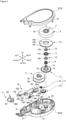
- Fig. 2 is an exploded top perspective view illustrating the coating film transfer tool 1 of Fig. 1 .
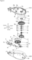
- Fig. 3 is an exploded bottom perspective view illustrating the coating film transfer tool 1 of Fig. 1 . Note that a transferable tape 3 pressed to a transfer target surface in a transfer head 5 is not illustrated intentionally in several drawings.
- a direction of transferring a coating film in a longitudinal direction of a casing 2 of the coating film transfer tool 1 will be referred to as a "front” direction, and its reverse direction will be referred to as a “rear” direction.
- a direction perpendicular to the longitudinal direction (front-rear direction) and a side where the transferable tape 3 before transferring the coating film passes in the transfer head 5 described below will be referred to as a "lower” side
- a side where the transferable tape 3 after transferring the coating film passes will be referred to as an "upper” side.
- a direction perpendicular to the front-rear direction and the up-down direction will be referred to as a left-right direction.
- the coating film transfer tool 1 is a so-called horizontal pulling type.
- the coating film transfer tool 1 has the casing 2 consisting of a pair of casing members including upper and lower casing members 21 and 22.
- the casing 2 houses (between the upper casing member 21 and the lower casing member 22) a feeding reel 4 around which the transferable tape 3 is wound, a base member 19 installed with the transfer head 5 that transfers the transferable tape 3 extracted from the feeding reel 4 to a transfer target surface, a winding reel 6 that winds the transferable tape 3 subjected to the transfer, and a power transmission mechanism 17 operated to synchronize the feeding reel 4 and the winding reel 6.
- a feeding reel support shaft 8 inside of the lower casing member 22, a feeding reel support shaft 8, a winding reel support shaft 13, a first guide pin 24 that guides the transferable tape 3 extracted from the feeding reel 4 to the transfer head 5, and a second guide pin 25 that guides the transferable tape 3 subjected to transfer from the transfer head 5 to the winding reel 6 are erected to extend toward the upper casing member 21.
- a feeding reel support shaft receptacle 8a into which the feeding reel support shaft 8 is inwardly inserted, a winding reel support shaft receptacle 13a into which the winding reel support shaft 13 is outwardly inserted, a first guide pin receptacle 24a into which the first guide pin 24 is inwardly inserted, and a second guide pin receptacle 25a into which the second guide pin 25 is inwardly inserted are provided on the inner surface of the upper casing member 21.
- a plurality of fitting assist pieces 2c are erected to extend toward the lower casing member 22.
- a plurality of fitting assist seat portions 2d where the plurality of fitting assist pieces 2c are fitted are provided.
- the feeding reel support shaft 8 provided in the lower casing member 22 is inwardly inserted into the feeding reel support shaft receptacle 8a while a feeding reel gear 7 and the feeding reel 4 are outwardly inserted rotatably.
- the feeding reel gear 7 has a tubular rotation shaft 7b provided with a locking portion 7a in its end.
- a compression spring 9, an annular first spacer 10, an annular elastic stopper 11, and an annular second spacer 12 are sequentially inserted into the rotation shaft 7b and are retained by the locking portion 7a.
- a locking protrusion 11a is provided on an outer circumferential surface of the elastic stopper 11. Meanwhile, a rib-shaped locking target portion 4a where the locking protrusion 11a is locked is provided on the inner circumferential surface of the feeding reel 4. As the locking protrusion 11a is locked to the rib-shaped locking target portion 4a, the elastic stopper 11 and the feeding reel 4 are rotated in synchronization.
- An outer circumferential surface of the upper half of the rotation shaft 7b of the feeding reel gear 7 is cut out at nearly equal intervals to form four plane portions 7c. Meanwhile, the corner portions of inner holes 10a and 12a of the first and second spacers 10 and 12 are formed in an arc-like quadrilateral shape as seen in a plan view.
- the plane portion 7c of the rotation shaft 7b adjoins with the sides of the quadrangles of the inner holes 10a and 12a of the first and second spacers 10 and 12, so that the first and second spacers 10 and 12 are irrotationally fitted to the rotation shaft 7b of the feeding reel gear 7.
- the feeding reel gear 7, the compression spring 9, the first spacer 10, and the second spacer 12 are rotated in synchronization.
- the winding reel 6 is outwardly inserted into the winding reel support shaft 13 erected on the inner surface of the lower casing member 22. As illustrated in Fig. 3 , a winding reel gear 14 is provided on the lower side surface of the winding reel 6. A first smaller gear 15 and a second smaller gear 16 are provided between the feeding reel gear 7 and the winding reel gear 14.
- the feeding reel gear 7 meshes with the first smaller gear 15.
- the first smaller gear 15 meshes with the second smaller gear 16.
- the second smaller gear 16 meshes with the winding reel gear 14.
- the rotation force of the feeding reel 4 is transmitted to the elastic stopper 11, and is transmitted to the feeding reel gear 7 by virtue of frictional forces generated between the side surface of the elastic stopper 11 and the side surface of the second spacer 12, between the side surface of the elastic stopper 11 and the side surface of the first spacer 10, and between the side surface of a flange 18 rotating in synchronization with the feeding reel 4 as described below and the side surface of the feeding reel gear 7.
- the rotation force is transmitted to the winding reel 6 through the power transmission mechanism 17 including the feeding reel gear 7, the first smaller gear 15, the second smaller gear 16, and the winding reel gear 14.
- the flange 18 for controlling rotation of the feeding reel 4 during a non-use state and a use state of the coating film transfer tool 1 is integrally provided in the feeding reel 4.
- a locking target teeth 18c described below are provided in the peripheral edge of the flange 18 (refer to Fig. 3 ).
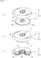
- Fig. 4 is a diagram illustrating a state in which the flange 18 is assembled with the feeding reel 4.
- Fig. 4(a) is a top perspective view illustrating a pre-assembly state
- Fig. 4(b) is a top perspective view illustrating an assembled state
- Fig. 4(c) is a cross-sectional perspective view taken along a line c-c of Fig. 4(b) .
- Installation pieces 18b having notches 18a are provided on the upper surface of the flange 18. As the rib-like locking target portion 4a of the feeding reel 4 is locked to the notches 18a of the installation pieces 18b, the feeding reel 4 and the flange 18 are assembled so as to rotate in synchronization.
- the coating film transfer tool 1 has the base member 19 and the transfer head 5 formed separately from the base member 19.
- Fig. 5 is a diagram illustrating the base member 19 having the transfer head 5 installed in a front end and a rotation restricting member 20 provided in a rear half portion.
- Fig. 5(a) is a perspective view
- Fig. 5(b) is an exploded perspective view
- Fig. 5(c) is an arrow view as seen from an arrow B of Fig. 5(a)
- Fig. 5(d) is a cross-sectional view.
- a protruding tip 191 protruding to the front side is provided in the leading end of the base member 19.
- a pair of protrusions 192 protruding perpendicularly to the extending direction of the protruding tip 191 (in the left-right direction) are formed on each of the side surfaces of the leading end of the base member 19.
- the transfer head 5 has a main body portion 5b having a pressing edge portion 5a formed in an approximately triangular shape on a cross section taken along the longitudinal direction and provided in the front end.
- the pressing edge portion 5a extends in the left-right direction perpendicular to the longitudinal direction in a portion where the coating film is transferred to the transfer target object.
- a hole portion 501 extending to the front side from the rear side of the longitudinal direction is provided in the center of the left-right direction on the rear end surface of the main body portion 5b.
- the protruding tip 191 is inserted into the hole portion 501.
- the transfer head 5 and the base member 19 are connected to each other.
- the front end of the hole portion 501 is placed in the vicinity of the pressing edge portion 5a.
- the front end of the protruding tip 191 is inserted at least to the vicinity of the pressing edge portion 5a.
- a distance d1 between the front end of the pressing edge portion 5a of the transfer head 5 and the front end of the protruding tip 191 when the protruding tip 191 is inserted into the hole portion 501 is preferably set to 0.3 to 8 mm, and more preferably, 0.5 to 4 mm.
- the main body portion 5b is pivotable about the protruding tip 191. Therefore, the pressing edge portion 5a becomes in parallel with the transfer target surface S1. In this state, while nipping the transferable tape 3 therebetween, the pressing edge portion 5a is pressed to the transfer target surface S1 and moves on the contact target surface S1. Then, the coating film held by the transferable tape 3 is transferred to the transfer target surface S1.
- the main body portion 5b including the pressing edge portion 5a in the transfer head 5 is preferably formed of a material having slight elasticity. If the pressing edge portion 5a has slight elasticity, adherence between the pressing edge portion 5a and the transfer target surface S1 is improved so as to provide an excellent transfer feeling.
- the transfer head 5 has a pair of tape guides 50 extending from the left and right side portions of the main body portion 5b to the rear side over the rear end surface of the main body portion 5b.
- Long holes 503 extending in the vertical direction (perpendicularly to the transfer surface of the transfer head 5) are formed in a pair of tape guides 50 backward of the main body portion 5b.
- the pair of tape guides 50 also cover the leading end side of the base member 19 while the protruding tip 191 of the base member 19 is inserted into the hole portion 501.
- the protrusions 192 of the base member 19 are inserted into the long holes 503. As a result, the transfer head 5 is connected to the base member 19.
- the vertical length of the long hole 503 is set to be longer than the diameter of the protrusion 192.
- the transfer head 5 connected to the leading end of the base member 19 becomes pivotable about the protruding tip 191 inserted into the hole portion 501.
- the transfer head 5 becomes pivotable within a range that the protrusion 192 can move inside the long hole 503. That is, the vertical length of the long hole 503 determines a pivotable range of the transfer head 5. In other words, the long hole 503 restricts the pivotable range of the transfer head 5.
- the pressing edge portion 5a of the transfer head 5 can be easily arranged in parallel with the transfer target surface. Therefore, it is not necessary for a user to elastically deform the pressing edge portion 5a by strongly pressing the transfer head 5 in order to arrange the pressing edge portion 5a of the transfer head 5 in parallel with the transfer target surface. Therefore, it is possible to uniformly transfer the coating film with a small transfer load.
- Fig. 6 is an exploded perspective view illustrating the base member 19 installed with the transfer head 5, a helical torsion spring 194, and the lower casing member 22.
- the base member 19 is biased such that the rotation restricting member 20 inhibits rotation of the feeding reel 4 with the helical torsion spring 194.
- the helical torsion spring 194 has a coil portion 194a, a first spring portion 194b extending from one end of the coil portion 194a, and a second spring portion 194c extending from the other end of the coil portion 194a.
- the helical torsion spring 194 biases the base member 19 so as to inhibit rotation of the feeding reel 4 by outwardly fitting the coil portion 194a to a support shaft 19a of the base member 19, fixing the first spring portion 194b to the lower surface side of the base member 19, and fixing the second spring portion 194c to the inner surface of the underlying lower casing member 22.
- a winding reel locking hook 20b is formed integrally with the base member 19 in an arm shape and has elasticity.
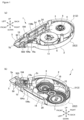
- Fig. 7 is a diagram illustrating a state of a base body in a use state and in a non-use state.
- Fig. 7(a) is a plan view illustrating the coating film transfer tool
- Fig. 7(b) is a cross-sectional view taken along a line D-D of Fig. 7(a) to illustrate a non-use state
- Fig. 7(c) is a cross-sectional view taken along a line D-D of Fig. 7(a) to illustrate a use state.
- the coating film transfer tool 1 has a restricting portion 193 that restricts the base member 19 from further pivoting from a position in which inhibition of rotation of the feeding reel 4 using the rotation restricting member 20 is released while the transfer head 5 is pressed to the transfer target surface S1 during a use state.
- the restricting portion 193 is formed integrally with the base member 19 and is arranged to protrude downward from the lower surface of the base member 19. More specifically, the restricting portion 193 is arranged in the vicinity of the support shaft 19a of the base member 19 backward of the support shaft 19a.
- the base member 19 is biased such that the rear end side is raised upward higher than the support shaft 19a by the helical torsion spring 194 during a non-use state as illustrated in Fig. 7(b) , and a feeding reel locking hook 20a of the rotation restricting member 20 is engaged with the locking target teeth 18c of the flange 18 rotating in synchronization with the feeding reel 4.
- the transfer head 5 is pressed to the transfer target surface S1 as illustrated in Fig. 7(c) . Therefore, the base member 19 is pivoted about the support shaft 19a such that the transfer head 5 moves upward resisting to the biasing force of the helical torsion spring 194. Then, the rotation restricting member 20 arranged oppositely to the transfer head 5 with respect to the support shaft 19a moves downward, so that the feeding reel locking hook 20a engaged with the locking target teeth 18c during a non-use state is disengaged from the locking target teeth 18c, and rotation inhibition of the feeding reel 4 is released.
- the winding reel locking hook 20b is formed in an arm shape and has elasticity as described above. As a result, even when locking between the feeding reel locking hook 20a and the locking target teeth 18c of the flange 18 of the feeding reel 4 is not released in order to prevent loosening during a non-use state, the winding reel locking hook 20b is elastically deformed so that the winding reel 6 can be rotated in a winding direction.
- the transfer head 5 has the pair of tape guides 50 in the left and right sides of the main body portion 5b.
- the pair of tape guides 50 include a right tape guide 51 and a left tape guide 52 arranged in parallel with each other.
- the right and left tape guides 51 and 52 have upper tape guides 51u and 52u, respectively, positioned in an upper part of the main body portion 5b and lower tape guides 51d and 52d, respectively, positioned in a lower part of the main body portion 5b.
- a gap dd between the pair of lower tape guides 51d and 52d provided in the left and right sides is set to, for example, -0.03 to +0.3 mm with respect to the width of the transferable tape 3.
- the front ends of the lower tape guides 51d and 52d are positioned in rear of the front ends of the upper tape guides 51u and 52u (only 52u is illustrated), and are separated from the leading end of the pressing edge portion 5a by a predetermined distance.
- the front sides of the lower tape guides 51d and 52d are obliquely inclined so as to descend backward from the front end.
- the front ends of the lower tape guides 51d and 52d are separated from the pressing edge portion 5a by a predetermined distance, and the front sides of the lower tape guides 51d and 52d are obliquely formed. Therefore, the lower tape guides 51d and 52d do not hinder contact between the pressing edge portion 5a and the transfer target surface S1 and a transfer of the transferable tape.
- a gap du between the front ends of the pair of upper tape guides 51u and 52u provided in the left and right sides is wider than the gap dd between the lower tape guides 51d and 52d.
- the gap du is preferably set to 0.5 mm or larger with respect to the width of the tape, and more preferably, 1 mm or larger and 3 mm or smaller with respect to the width of the tape.
- the front ends of the upper tape guides 51u and 52u are placed in the vicinity of the pressing edge portion 5a in front of the lower tape guides 51d and 52d.
- the front sides of the upper tape guides 51u and 52u have an arc shape curved rearward from the front end to the upper side, so that the upper tape guides 51u and 52u have a fan shape.
- the front ends of the upper tape guides 51u and 52u are placed slightly in rear of the front end of the pressing edge portion 5a (that is, not far from the pressing edge portion 5a).
- the front ends of the upper tape guides 51u and 52u are portions of the upper tape guides 51u and 52u placed frontmost in the tape path.
- the gap du between the front ends of the upper tape guides 51u and 52u is wider than the narrowest gap between the lower tape guides 51d and 52d in the tape path.
- the gap du between the front ends of the upper tape guides 51u and 52u is preferably wider than the widest gap between the lower tape guides 51d and 52d in the tape path.
- the transferable tape 3 is manufactured, for example, by forming a release layer such as silicon resin on one or both surfaces of a long body formed of a plastic film such as polyethylene terephthalate, polypropylene, and polyethylene or paper with a thickness of 3 to 60 ⁇ m as a base material, and coating an adhesive or the like on one surface of the base material using a method known in the art.
- a release layer such as silicon resin
- a plastic film such as polyethylene terephthalate, polypropylene, and polyethylene or paper with a thickness of 3 to 60 ⁇ m as a base material
- the adhesive includes an acrylic resin-based adhesive, a vinyl resin-based adhesive, a rosin-based adhesive, a rubber-based adhesive, or a mixture obtained by mixing an agent such as a crosslinking agent, a tackifier, a plasticizer, an antioxidant, a filler, a thickener, a pH adjuster, and an antifoaming agent with such an adhesive as appropriate.
- a tape having the adhesive layer provided on one surface of the base material is an adhesive tape (tape paste).
- a tape having an opaque layer formed of pigments having opacity and polymer resin as a binder or the like provided on one surface of the base material and an adhesive layer formed thereon is a corrective tape.
- a tape having a fluorescent coloring layer provided on one surface of the base material and an adhesive layer formed thereon is a fluorescent tape.
- the layer formed on one surface of the base material has a thickness of 0.3 to 60 ⁇ m, for example, after drying.
- the transferable tape 3 has a width of approximately 2 to 15 mm.
- the center of the pressing edge portion 5a is pressed, and the force is distributed from the center to the left and right directions. Therefore, a state in which the coating film is not transferred in the center of the coating film is not easily generated regardless of the transfer load. In addition, cracking of the transferred coating film or chipping of the coating film during writing does not easily occur.
- the transfer head 5 is pivotable about the protruding tip 191 inserted into the hole portion 501.
- the main body portion 5b is pivotable about the protruding tip 191. Therefore, the pressing edge portion 5a can abut on the transfer target surface without twisting or deforming the protruding tip 191.
- the protruding tip 191 and the main body portion 5b are separate members, they can be manufactured using different materials. Therefore, it is possible to manufacture the main body portion 5b with a material having small elasticity unlike the protruding tip 191.
- the main body portion 5b is manufactured of a material having elasticity, compared to the protruding tip 191, it is possible to further improve adherence between the main body portion 5b (pressing edge portion 5a) and the transfer target surface S1. Therefore, it is possible to improve a transfer feeling. Furthermore, it is possible to further prevent a state in which the coating film is not transferred in the center of the coating film.
- a shaft of the main body portion may be lengthened to the rear side and may be connected to the casing or the base member.
- a structure for pivotally receiving the shaft is necessary in the casing or the base member. This accordingly increases the thickness of the casing.
- the thinner casing is desirable in terms of storability.
- an axial support structure (the protruding tip 191 and the hole portion 501) is in the transfer head 5 side. Therefore, the casing 2 is not thickened. Note that, since the transfer head 5 side has space, the entire size of the coating film transfer tool 1 does not increase even when the structure for receiving the protruding tip 191 such as the hole portion 501 is provided.
- the transfer head 5 is compact. Therefore, pivoting to follow the transfer target surface becomes easy.
- the gap between the lower tape guides 51d and 52d is nearly equal to the width of the transferable tape 3. Therefore, the lower tape guides 51d and 52d may come into contact with the transferable tape 3, and the edge of the transferable tape 3 may be slightly twisted (flexed, deformed, or distorted).
- the transferable tape 3 is recovered to its original shape by virtue of a restoring force or a tensile force of the transferable tape 3 by further feeding the transferable tape 3 from the position coming into contact with the lower tape guides 51d and 52d to move forward.
- the transferable tape 3 may be transferred while the edge of the transferable tape 3 is bent in the pressing operation.
- This portion is not transferred to the transfer target surface and may reduce the width of the coating film or generate a partial damage to the coating film.
- the gap between the upper tape guides 51u and 52u arranged in the vicinity of the pressing edge portion 5a is wider than the gap between the lower tape guides 51d and 52d. Therefore, even when the transfer head 5 is inclined, a possibility of contact with the upper tape guides 51u and 52u is low.
- the transfer head 5 As the pressing force of the transfer head 5 to the transfer target surface is released after the transfer, the transfer head 5 is returned to a specified position by virtue of a restoring force or a tensile force of the transferable tape 3 (to a position where the transfer head 5 is not rotated or a direction in which the pressing edge portion 5a becomes perpendicular to the feeding direction of the transferable tape 3).
- the coating film transfer tool 1 is the so-called horizontal pulling type coating film transfer tool 1 in which a direction of the pressing edge portion 5a placed in the front end of the transfer head 5 to press the transferable tape 3 to the transfer target surface is substantially perpendicular to the feeding reel support shaft 8 of the feeding reel 4 and the winding reel support shaft 13 of the winding reel 6.
- a direction of the pressing edge portion 5a placed in the front end of the transfer head 5 to press the transferable tape 3 to the transfer target surface is substantially perpendicular to the feeding reel support shaft 8 of the feeding reel 4 and the winding reel support shaft 13 of the winding reel 6.
- Fig. 8 illustrates a second embodiment.
- Fig. 8(a) is a perspective view illustrating the transfer head 5 and a part of the base member 19 including the protruding tip 191
- Fig. 8(b) is an exploded perspective view illustrating the transfer head 5 and a part of the base member 19 including the protruding tip 191.
- Fig. 9 illustrates a second embodiment.
- Fig. 9(a) is a top view illustrating the transfer head 5 and a part of the base member 19 including the protruding tip 191
- Fig. 9(b) is a cross-sectional view taken along a line AA-AA of Fig. 9(a)
- Fig. 9(c) is a cross-sectional view taken along a line AB-AB of Fig. 9(a) .
- the second embodiment is different from the first embodiment in the structure of the connecting portion between the transfer head 5 and the base member 19.
- Like reference numerals denote like elements as in the first embodiment, and they will not be described.
- the base member 19 includes a first portion 195 formed by bulging a predetermined area including the center of the left-right direction of the front end by a predetermined height in the front end portion, a second portion 196 that is bent from the upper end of the first portion 195 and extends forward, a third portion 197 that is bent from the second portion 196 and extends downward, and the protruding tip 191 extending forward from the lower end of the third portion 197.
- the protruding tip 191 is shaped to have an approximately uniform thickness in the vertical direction while a triangular horizontal cross-sectional portion is installed in a leading end of a rectangular horizontal cross-sectional portion.
- a front end surface of the base member 19, a front surface of the first portion 195, a lower surface of the second portion 196, a rear surface of the third portion 197, and an upper surface of a fourth portion 198 that is placed in rear of the protruding tip 191 and protrudes slightly backward of the rear surface of the third portion 197 constitute an engagement portion 199 extending in the left-right direction in an approximately rectangular vertical cross-sectional shape.
- the engagement portion 199 is engaged with a crossbar portion 5c described below.
- the transfer head 5 includes the main body portion 5b and the pressing edge portion 5a that is provided in front of the main body portion 5b and has a rectangular parallelepiped horizontal cross section and an approximately triangular vertical cross section along the longitudinal direction.
- the hole portion 501 extending from the rear surface to the front side is provided on the rear surface of the pressing edge portion 5a serving as a connecting side to the main body portion 5b.
- a horizontal cross section of the hole portion 501 has a triangular shape matching the triangular shape of the leading end of the protruding tip 191.
- the vertical width of the hole portion 501 is approximately uniform to match the vertical width of the protruding tip 191 so as to receive the inserted protruding tip 191.
- the hole portion 501 has a horizontal bottom surface continuous to the upper surface of the main body portion 5b so as to allow the protruding tip 191 to be smoothly inserted.
- the crossbar portion 5c bridged between the right and left tape guides 51 and 52 is provided over the rear end of the main body portion 5b. As the protruding tip 191 is inserted into the hole portion 501, the crossbar portion 5c is engaged with the engagement portion 199 described above, so that the transfer head 5 is installed in the base member 19.
- the front end of the hole portion 501 be placed in the vicinity of the pressing edge portion 5a.
- the distance d1 between the front end of the pressing edge portion 5a of the transfer head 5 and the front end of the protruding tip 191 be set to 0.3 to 8 mm, and more preferably, 0.5 to 4 mm when the protruding tip 191 is inserted into the hole portion 501.
- the transfer head 5 is not pivoted about the base member 19 according to the second embodiment.
- the protruding tip 191 presses the inner surface of the hole portion 501 downward, so that a part of the area including the center of the left-right direction of the main body portion is pressed.
- a state in which the coating film is not transferred in the center of the coating film is not easily generated.
- cracking in the transferred coating film or chipping of the coating film during writing is not easily generated.
- the shapes of the protruding tip and the hole portion are not limited to those of the embodiments.
- they may have another pivotable configuration relationship in which the protruding tip has a circular columnar shape, and the hole portion has a shape matching the circular columnar shape.
- the protruding tip may have a rectangular parallelepiped shape, a triangular prism shape, or the like.
Landscapes
- Adhesive Tape Dispensing Devices (AREA)
- Decoration By Transfer Pictures (AREA)
- Coating Apparatus (AREA)
- Pens And Brushes (AREA)
Applications Claiming Priority (1)
| Application Number | Priority Date | Filing Date | Title |
|---|---|---|---|
| JP2017131409A JP7095856B2 (ja) | 2017-07-04 | 2017-07-04 | 塗膜転写具 |
Publications (2)
| Publication Number | Publication Date |
|---|---|
| EP3424855A1 EP3424855A1 (en) | 2019-01-09 |
| EP3424855B1 true EP3424855B1 (en) | 2024-10-23 |
Family
ID=62874577
Family Applications (1)
| Application Number | Title | Priority Date | Filing Date |
|---|---|---|---|
| EP18181354.4A Active EP3424855B1 (en) | 2017-07-04 | 2018-07-03 | Coating film transfer tool |
Country Status (6)
| Country | Link |
|---|---|
| US (1) | US10981746B2 (enExample) |
| EP (1) | EP3424855B1 (enExample) |
| JP (1) | JP7095856B2 (enExample) |
| KR (1) | KR102462609B1 (enExample) |
| CN (1) | CN109203794B (enExample) |
| TW (1) | TWI774782B (enExample) |
Families Citing this family (7)
| Publication number | Priority date | Publication date | Assignee | Title |
|---|---|---|---|---|
| JP1574143S (enExample) * | 2016-07-01 | 2017-04-17 | ||
| EP3689634B1 (en) * | 2017-09-29 | 2023-10-04 | Fujicopian Co., Ltd. | Coating film transfer tool |
| USD880586S1 (en) * | 2017-12-21 | 2020-04-07 | Tombow Pencil Co., Ltd. | Correction tape dispenser |
| CN112848763A (zh) * | 2021-02-25 | 2021-05-28 | 得力集团有限公司 | 一种修正带静音结构及修正带 |
| WO2022216638A1 (en) * | 2021-04-05 | 2022-10-13 | Sandar Industries, Inc | Improved methods and apparatus for separating and spooling a paper web |
| JP7848038B2 (ja) * | 2022-04-13 | 2026-04-20 | コクヨ株式会社 | 転写具 |
| CN116144914A (zh) * | 2022-11-09 | 2023-05-23 | 中国航发沈阳黎明航空发动机有限责任公司 | 一种叶片激光冲击强化吸收层布置手持装置 |
Citations (3)
| Publication number | Priority date | Publication date | Assignee | Title |
|---|---|---|---|---|
| JP2002274097A (ja) * | 2001-03-16 | 2002-09-25 | Plus Stationery Corp | 塗布膜転写具 |
| EP2070856A1 (en) * | 2007-12-14 | 2009-06-17 | Société BIC | A hand-held device for applying a deposit of for example adhesive, covering or coloured material onto a correction surface |
| WO2013180101A1 (ja) * | 2012-05-31 | 2013-12-05 | フジコピアン株式会社 | 塗膜転写具 |
Family Cites Families (75)
| Publication number | Priority date | Publication date | Assignee | Title |
|---|---|---|---|---|
| JPS577499A (en) | 1980-06-13 | 1982-01-14 | Mitsubishi Chem Ind Ltd | Improved preparation of steroid 17-ester |
| IT1207824B (it) | 1987-01-22 | 1989-06-01 | Conti Giuseppe Off Mec | Dispositivo di alimentazione dei punti di nastro collato per legatrice di moduli continui di tabulatrici |
| JPH0288057A (ja) | 1988-09-26 | 1990-03-28 | Oji Paper Co Ltd | 衛生用品の表面材 |
| WO1990014299A1 (en) | 1989-05-20 | 1990-11-29 | Fujikagakushi Kogyo Kabushiki Kaisha | Transcriber of transfer film |
| JPH085277B2 (ja) | 1990-10-05 | 1996-01-24 | 秀雄 浜田 | 転写シート |
| JPH05178525A (ja) | 1991-12-26 | 1993-07-20 | Fujicopian Co Ltd | 塗膜転写具 |
| DE4137936A1 (de) | 1991-11-18 | 1993-05-19 | Pelikan Ag | Transferklebeband |
| JPH0673025U (ja) | 1993-03-30 | 1994-10-11 | 三菱鉛筆株式会社 | 修正テープの貼付具 |
| GB9422905D0 (en) * | 1994-11-14 | 1995-01-04 | Gillette Co | Tape dispensers |
| JP3027309B2 (ja) | 1994-12-12 | 2000-04-04 | シードゴム工業株式会社 | 塗膜転写具用テープカートリッジおよび塗膜転写具 |
| JP2943134B2 (ja) | 1995-11-01 | 1999-08-30 | シードゴム工業株式会社 | 塗膜転写具用テープカートリッジおよび塗膜転写具 |
| JPH0971097A (ja) | 1995-09-07 | 1997-03-18 | Tombow Pencil Co Ltd | 塗布具の転写テープ送出、巻取り部 |
| JP2876301B2 (ja) | 1995-10-06 | 1999-03-31 | シードゴム工業株式会社 | 塗膜転写具のクラッチ機構および塗膜転写具 |
| JP3516188B2 (ja) | 1995-10-27 | 2004-04-05 | 株式会社トンボ鉛筆 | 塗布具の転写テープ送出、巻取り部 |
| JP2975895B2 (ja) | 1996-08-09 | 1999-11-10 | シードゴム工業株式会社 | 塗膜転写用ヘッド、塗膜転写具および塗膜転写具の組立方法 |
| JPH10181289A (ja) | 1996-12-27 | 1998-07-07 | Fujicopian Co Ltd | 塗膜転写具 |
| JP3813681B2 (ja) * | 1997-02-10 | 2006-08-23 | ゼネラル株式会社 | 感圧転写具 |
| JP3870986B2 (ja) | 1997-04-24 | 2007-01-24 | 株式会社トンボ鉛筆 | 塗布具の供給リール |
| JPH111095A (ja) | 1997-06-12 | 1999-01-06 | Tombow Pencil Co Ltd | 塗布具の転写テープ送出、巻取り機構 |
| JPH11227385A (ja) * | 1998-02-12 | 1999-08-24 | Fujicopian Co Ltd | 塗膜転写具 |
| JP2000025392A (ja) | 1998-07-08 | 2000-01-25 | Seed Rubber Kogyo Kk | 塗膜転写具用テープカートリッジおよび塗膜転写具 |
| US5991568A (en) | 1998-12-23 | 1999-11-23 | Eastman Kodak Company | Blade cleaning apparatus with associated dust seal and method of cleaning |
| DE19936445B4 (de) | 1999-08-03 | 2004-03-04 | SOCIéTé BIC | Handgerät zum Übertragen eines Filmes von einem Trägerband auf ein Substrat |
| JP2001089011A (ja) | 1999-09-21 | 2001-04-03 | Plus Kogyo Kk | 塗布膜転写具における転写ヘッド |
| JP3069561B1 (ja) | 1999-10-15 | 2000-07-24 | ニチハ株式会社 | 建築板の製造方法及び建築板 |
| JP3518469B2 (ja) | 2000-03-01 | 2004-04-12 | 株式会社トンボ鉛筆 | 感圧転写粘着テープ |
| JP2002264587A (ja) * | 2001-03-07 | 2002-09-18 | Tombow Pencil Co Ltd | 塗膜転写具 |
| US6510884B1 (en) | 2001-04-12 | 2003-01-28 | C. C. & L Company Limited | Adhesive tape dispenser |
| JP4677626B2 (ja) * | 2001-06-21 | 2011-04-27 | フジコピアン株式会社 | 塗膜転写具 |
| JP4603738B2 (ja) * | 2001-09-28 | 2010-12-22 | プラス株式会社 | 塗布膜転写具 |
| JP3747285B2 (ja) * | 2003-03-07 | 2006-02-22 | 光浩 柳 | 接着テープ転写具 |
| JP4172308B2 (ja) | 2003-03-31 | 2008-10-29 | コベルコ建機株式会社 | 建設機械のフロア構造組み立て方法およびフロアマット |
| JP4205518B2 (ja) | 2003-07-31 | 2009-01-07 | 株式会社トンボ鉛筆 | 塗膜転写具 |
| US7228882B2 (en) | 2003-09-15 | 2007-06-12 | Sanford, L.P. | Tape dispenser with a cushioned applicator tip |
| US6997229B2 (en) * | 2003-09-16 | 2006-02-14 | Sanford, L.P. | Rotatable applicator tip for a corrective tape dispenser |
| JP4144798B2 (ja) | 2003-11-28 | 2008-09-03 | 日立マクセル株式会社 | 密閉型電池 |
| US7163040B2 (en) | 2004-01-13 | 2007-01-16 | Sanford L.P. | Correction tape applicator tip with cylindrical projection |
| US7070051B2 (en) | 2004-03-26 | 2006-07-04 | Atrion Medical Products, Inc. | Needle counter device including troughs of cohesive material |
| TWM271730U (en) | 2004-10-26 | 2005-08-01 | Sdi Corp | Pushbutton controlled correction tape |
| JP2006281495A (ja) | 2005-03-31 | 2006-10-19 | Tombow Pencil Co Ltd | 塗膜転写具 |
| US20060251888A1 (en) | 2005-05-06 | 2006-11-09 | Richard Lane | Pressure sensitive adhesive (PSA) laminates |
| US20060251889A1 (en) | 2005-05-06 | 2006-11-09 | Richard Lane | Pressure sensitive adhesive (PSA) laminates |
| US20060263596A1 (en) | 2005-05-06 | 2006-11-23 | Bamborough Derek W | Pressure sensitive adhesives (PSA) laminates |
| US20060251890A1 (en) | 2005-05-06 | 2006-11-09 | Richard Lane | Pressure sensitive adhesive (PSA) laminates |
| JP4652955B2 (ja) * | 2005-11-21 | 2011-03-16 | プラス株式会社 | 塗布膜転写具 |
| JP2007154022A (ja) | 2005-12-05 | 2007-06-21 | Nippon Ester Co Ltd | 難燃性ポリエステル及びその製造方法 |
| EP1808395B1 (en) | 2006-01-12 | 2008-07-16 | Société BIC | Correction system with rubber elastic tension element for a gear mechanism correction tape |
| JP4769964B2 (ja) | 2006-02-06 | 2011-09-07 | フジコピアン株式会社 | 塗膜転写具 |
| JP5085145B2 (ja) | 2006-03-15 | 2012-11-28 | 日東電工株式会社 | 両面粘着テープ又はシート、および液晶表示装置 |
| US20070231571A1 (en) | 2006-04-04 | 2007-10-04 | Richard Lane | Pressure sensitive adhesive (PSA) laminates |
| JP4762044B2 (ja) | 2006-04-27 | 2011-08-31 | 矢崎総業株式会社 | 負荷回路の保護装置 |
| JP4824470B2 (ja) * | 2006-05-22 | 2011-11-30 | ゼネラル株式会社 | 転写具 |
| JP2008096389A (ja) | 2006-10-16 | 2008-04-24 | Chugoku Electric Power Co Inc:The | 電子機器、時刻管理装置、時刻設定プログラム、時刻設定方法 |
| JP2008162052A (ja) | 2006-12-27 | 2008-07-17 | Kokuyo Co Ltd | 転写具 |
| JP4737642B2 (ja) | 2007-05-09 | 2011-08-03 | ニチバン株式会社 | 粘着転写具 |
| JP4929477B2 (ja) | 2007-07-27 | 2012-05-09 | コクヨ株式会社 | 転写具 |
| JP4974291B2 (ja) | 2007-10-02 | 2012-07-11 | ユニオンケミカー株式会社 | 塗膜転写具 |
| CN201154628Y (zh) * | 2007-12-24 | 2008-11-26 | 上海橘林文具有限公司 | 按压式修正带 |
| JP5005561B2 (ja) | 2008-01-18 | 2012-08-22 | プラス株式会社 | 塗膜転写具 |
| JP5685697B2 (ja) | 2008-05-29 | 2015-03-18 | 有限会社フジカ | 人工降雨発生方法 |
| JP2010002733A (ja) | 2008-06-20 | 2010-01-07 | Fuji Xerox Co Ltd | 平板状素子付き基板、これを用いた表示媒体および平板状素子付き基板の製造方法 |
| WO2010027507A2 (en) | 2008-09-08 | 2010-03-11 | Eastman Chemical Company | Washable psa laminates |
| JP5747143B2 (ja) | 2009-12-08 | 2015-07-08 | コクヨ株式会社 | 転写具 |
| JP5416862B2 (ja) | 2010-04-02 | 2014-02-12 | アドヴェニラ エンタープライジーズ,インコーポレイテッド | ロールコータ |
| JP5644178B2 (ja) | 2010-05-25 | 2014-12-24 | ぺんてる株式会社 | 塗膜転写具 |
| JP2012195747A (ja) | 2011-03-16 | 2012-10-11 | Nippon Signal Co Ltd:The | 個別情報保護システム |
| US8951381B2 (en) | 2011-04-25 | 2015-02-10 | First Solar, Inc. | Quick release head for tape applicator |
| JP5857892B2 (ja) | 2012-07-03 | 2016-02-10 | 株式会社オートネットワーク技術研究所 | 多極コネクタ |
| JP5989434B2 (ja) | 2012-07-18 | 2016-09-07 | 日東電工株式会社 | 表面保護シート |
| CN103797390B (zh) | 2012-08-09 | 2016-01-20 | 株式会社藤仓 | 光连接器清扫工具以及光连接器清扫方法 |
| US10807757B2 (en) | 2013-04-26 | 2020-10-20 | Avery Dennison Corporation | Method and apparatus for dispensing pressure sensitive adhesive labels onto a substrate |
| JP6247199B2 (ja) | 2014-12-09 | 2017-12-13 | 株式会社トンボ鉛筆 | 塗膜転写具 |
| JP6321537B2 (ja) | 2014-12-26 | 2018-05-09 | 株式会社トンボ鉛筆 | 塗膜転写具 |
| JP2017149034A (ja) | 2016-02-25 | 2017-08-31 | プラス株式会社 | 塗膜転写具 |
| CN109414951B (zh) | 2016-06-24 | 2020-08-07 | 株式会社蜻蜓铅笔 | 横拉型涂膜转印具 |
-
2017
- 2017-07-04 JP JP2017131409A patent/JP7095856B2/ja active Active
-
2018
- 2018-06-07 TW TW107119578A patent/TWI774782B/zh active
- 2018-06-19 KR KR1020180070053A patent/KR102462609B1/ko active Active
- 2018-07-03 EP EP18181354.4A patent/EP3424855B1/en active Active
- 2018-07-03 US US16/026,322 patent/US10981746B2/en active Active
- 2018-07-03 CN CN201810717616.9A patent/CN109203794B/zh active Active
Patent Citations (3)
| Publication number | Priority date | Publication date | Assignee | Title |
|---|---|---|---|---|
| JP2002274097A (ja) * | 2001-03-16 | 2002-09-25 | Plus Stationery Corp | 塗布膜転写具 |
| EP2070856A1 (en) * | 2007-12-14 | 2009-06-17 | Société BIC | A hand-held device for applying a deposit of for example adhesive, covering or coloured material onto a correction surface |
| WO2013180101A1 (ja) * | 2012-05-31 | 2013-12-05 | フジコピアン株式会社 | 塗膜転写具 |
Also Published As
| Publication number | Publication date |
|---|---|
| EP3424855A1 (en) | 2019-01-09 |
| CN109203794B (zh) | 2022-05-24 |
| KR20190004647A (ko) | 2019-01-14 |
| CN109203794A (zh) | 2019-01-15 |
| JP7095856B2 (ja) | 2022-07-05 |
| JP2019014086A (ja) | 2019-01-31 |
| US10981746B2 (en) | 2021-04-20 |
| KR102462609B1 (ko) | 2022-11-03 |
| US20190010009A1 (en) | 2019-01-10 |
| TWI774782B (zh) | 2022-08-21 |
| TW201906745A (zh) | 2019-02-16 |
Similar Documents
| Publication | Publication Date | Title |
|---|---|---|
| EP3424855B1 (en) | Coating film transfer tool | |
| EP3476619A1 (en) | Horizontal pulling type coating film transfer tool | |
| US7093640B2 (en) | Tape dispenser having a retaining and application area | |
| KR102236551B1 (ko) | 도막 전사구 | |
| US10150640B2 (en) | Coating film transfer tool including a roller for removing debris adhered to a transfer roller | |
| KR20090079826A (ko) | 코팅필름 전사도구 | |
| TW522101B (en) | Tape cartridge for coat film transfer tool and coat film transfer tool | |
| JP4769964B2 (ja) | 塗膜転写具 | |
| EP3650241B1 (en) | Coating film transfer tool | |
| US10717316B2 (en) | Coating film transfer tool | |
| US7139011B2 (en) | Ink sheet cartridge and exchangeable ink sheet set | |
| JP5314804B1 (ja) | テープカッタ | |
| JP2008307815A (ja) | 転写具 | |
| JP2002283795A (ja) | 塗膜転写具 | |
| JP5618362B2 (ja) | 塗膜転写具 | |
| US20150321869A1 (en) | Transfer tool | |
| US20200277157A1 (en) | Heavy duty tape dispenser | |
| JP2001089011A (ja) | 塗布膜転写具における転写ヘッド | |
| IT8124911A1 (it) | Procedimento per il montaggio di una spilla di sicurezza dotata di un elemento di bloccaggio e spilla di sicurezza cosi' ottenuta | |
| JPH0586953U (ja) | 転写式修正具 | |
| CN113815339A (zh) | 转印用具 | |
| US11981528B2 (en) | Coating transfer tool | |
| JP2004284179A (ja) | 塗膜転写具 | |
| JP2019119159A (ja) | 転写具 | |
| JP2017202566A (ja) | 塗膜転写具 |
Legal Events
| Date | Code | Title | Description |
|---|---|---|---|
| PUAI | Public reference made under article 153(3) epc to a published international application that has entered the european phase |
Free format text: ORIGINAL CODE: 0009012 |
|
| STAA | Information on the status of an ep patent application or granted ep patent |
Free format text: STATUS: THE APPLICATION HAS BEEN PUBLISHED |
|
| AK | Designated contracting states |
Kind code of ref document: A1 Designated state(s): AL AT BE BG CH CY CZ DE DK EE ES FI FR GB GR HR HU IE IS IT LI LT LU LV MC MK MT NL NO PL PT RO RS SE SI SK SM TR |
|
| AX | Request for extension of the european patent |
Extension state: BA ME |
|
| STAA | Information on the status of an ep patent application or granted ep patent |
Free format text: STATUS: REQUEST FOR EXAMINATION WAS MADE |
|
| 17P | Request for examination filed |
Effective date: 20190704 |
|
| RBV | Designated contracting states (corrected) |
Designated state(s): AL AT BE BG CH CY CZ DE DK EE ES FI FR GB GR HR HU IE IS IT LI LT LU LV MC MK MT NL NO PL PT RO RS SE SI SK SM TR |
|
| STAA | Information on the status of an ep patent application or granted ep patent |
Free format text: STATUS: EXAMINATION IS IN PROGRESS |
|
| 17Q | First examination report despatched |
Effective date: 20220509 |
|
| GRAP | Despatch of communication of intention to grant a patent |
Free format text: ORIGINAL CODE: EPIDOSNIGR1 |
|
| STAA | Information on the status of an ep patent application or granted ep patent |
Free format text: STATUS: GRANT OF PATENT IS INTENDED |
|
| INTG | Intention to grant announced |
Effective date: 20240808 |
|
| GRAS | Grant fee paid |
Free format text: ORIGINAL CODE: EPIDOSNIGR3 |
|
| GRAA | (expected) grant |
Free format text: ORIGINAL CODE: 0009210 |
|
| STAA | Information on the status of an ep patent application or granted ep patent |
Free format text: STATUS: THE PATENT HAS BEEN GRANTED |
|
| AK | Designated contracting states |
Kind code of ref document: B1 Designated state(s): AL AT BE BG CH CY CZ DE DK EE ES FI FR GB GR HR HU IE IS IT LI LT LU LV MC MK MT NL NO PL PT RO RS SE SI SK SM TR |
|
| REG | Reference to a national code |
Ref country code: GB Ref legal event code: FG4D |
|
| REG | Reference to a national code |
Ref country code: CH Ref legal event code: EP |
|
| REG | Reference to a national code |
Ref country code: DE Ref legal event code: R096 Ref document number: 602018075677 Country of ref document: DE |
|
| REG | Reference to a national code |
Ref country code: IE Ref legal event code: FG4D |
|
| P01 | Opt-out of the competence of the unified patent court (upc) registered |
Free format text: CASE NUMBER: APP_60056/2024 Effective date: 20241106 |
|
| REG | Reference to a national code |
Ref country code: LT Ref legal event code: MG9D |
|
| REG | Reference to a national code |
Ref country code: NL Ref legal event code: MP Effective date: 20241023 |
|
| REG | Reference to a national code |
Ref country code: AT Ref legal event code: MK05 Ref document number: 1734692 Country of ref document: AT Kind code of ref document: T Effective date: 20241023 |
|
| PG25 | Lapsed in a contracting state [announced via postgrant information from national office to epo] |
Ref country code: NL Free format text: LAPSE BECAUSE OF FAILURE TO SUBMIT A TRANSLATION OF THE DESCRIPTION OR TO PAY THE FEE WITHIN THE PRESCRIBED TIME-LIMIT Effective date: 20241023 |
|
| PG25 | Lapsed in a contracting state [announced via postgrant information from national office to epo] |
Ref country code: NL Free format text: LAPSE BECAUSE OF FAILURE TO SUBMIT A TRANSLATION OF THE DESCRIPTION OR TO PAY THE FEE WITHIN THE PRESCRIBED TIME-LIMIT Effective date: 20241023 |
|
| PG25 | Lapsed in a contracting state [announced via postgrant information from national office to epo] |
Ref country code: HR Free format text: LAPSE BECAUSE OF FAILURE TO SUBMIT A TRANSLATION OF THE DESCRIPTION OR TO PAY THE FEE WITHIN THE PRESCRIBED TIME-LIMIT Effective date: 20241023 Ref country code: PT Free format text: LAPSE BECAUSE OF FAILURE TO SUBMIT A TRANSLATION OF THE DESCRIPTION OR TO PAY THE FEE WITHIN THE PRESCRIBED TIME-LIMIT Effective date: 20250224 Ref country code: IS Free format text: LAPSE BECAUSE OF FAILURE TO SUBMIT A TRANSLATION OF THE DESCRIPTION OR TO PAY THE FEE WITHIN THE PRESCRIBED TIME-LIMIT Effective date: 20250223 |
|
| PG25 | Lapsed in a contracting state [announced via postgrant information from national office to epo] |
Ref country code: FI Free format text: LAPSE BECAUSE OF FAILURE TO SUBMIT A TRANSLATION OF THE DESCRIPTION OR TO PAY THE FEE WITHIN THE PRESCRIBED TIME-LIMIT Effective date: 20241023 |
|
| PG25 | Lapsed in a contracting state [announced via postgrant information from national office to epo] |
Ref country code: BG Free format text: LAPSE BECAUSE OF FAILURE TO SUBMIT A TRANSLATION OF THE DESCRIPTION OR TO PAY THE FEE WITHIN THE PRESCRIBED TIME-LIMIT Effective date: 20241023 |
|
| PG25 | Lapsed in a contracting state [announced via postgrant information from national office to epo] |
Ref country code: ES Free format text: LAPSE BECAUSE OF FAILURE TO SUBMIT A TRANSLATION OF THE DESCRIPTION OR TO PAY THE FEE WITHIN THE PRESCRIBED TIME-LIMIT Effective date: 20241023 |
|
| PG25 | Lapsed in a contracting state [announced via postgrant information from national office to epo] |
Ref country code: NO Free format text: LAPSE BECAUSE OF FAILURE TO SUBMIT A TRANSLATION OF THE DESCRIPTION OR TO PAY THE FEE WITHIN THE PRESCRIBED TIME-LIMIT Effective date: 20250123 |
|
| PG25 | Lapsed in a contracting state [announced via postgrant information from national office to epo] |
Ref country code: GR Free format text: LAPSE BECAUSE OF FAILURE TO SUBMIT A TRANSLATION OF THE DESCRIPTION OR TO PAY THE FEE WITHIN THE PRESCRIBED TIME-LIMIT Effective date: 20250124 Ref country code: AT Free format text: LAPSE BECAUSE OF FAILURE TO SUBMIT A TRANSLATION OF THE DESCRIPTION OR TO PAY THE FEE WITHIN THE PRESCRIBED TIME-LIMIT Effective date: 20241023 Ref country code: LV Free format text: LAPSE BECAUSE OF FAILURE TO SUBMIT A TRANSLATION OF THE DESCRIPTION OR TO PAY THE FEE WITHIN THE PRESCRIBED TIME-LIMIT Effective date: 20241023 |
|
| PG25 | Lapsed in a contracting state [announced via postgrant information from national office to epo] |
Ref country code: PL Free format text: LAPSE BECAUSE OF FAILURE TO SUBMIT A TRANSLATION OF THE DESCRIPTION OR TO PAY THE FEE WITHIN THE PRESCRIBED TIME-LIMIT Effective date: 20241023 |
|
| PG25 | Lapsed in a contracting state [announced via postgrant information from national office to epo] |
Ref country code: RS Free format text: LAPSE BECAUSE OF FAILURE TO SUBMIT A TRANSLATION OF THE DESCRIPTION OR TO PAY THE FEE WITHIN THE PRESCRIBED TIME-LIMIT Effective date: 20250123 |
|
| PG25 | Lapsed in a contracting state [announced via postgrant information from national office to epo] |
Ref country code: SM Free format text: LAPSE BECAUSE OF FAILURE TO SUBMIT A TRANSLATION OF THE DESCRIPTION OR TO PAY THE FEE WITHIN THE PRESCRIBED TIME-LIMIT Effective date: 20241023 |
|
| PG25 | Lapsed in a contracting state [announced via postgrant information from national office to epo] |
Ref country code: DK Free format text: LAPSE BECAUSE OF FAILURE TO SUBMIT A TRANSLATION OF THE DESCRIPTION OR TO PAY THE FEE WITHIN THE PRESCRIBED TIME-LIMIT Effective date: 20241023 |
|
| PG25 | Lapsed in a contracting state [announced via postgrant information from national office to epo] |
Ref country code: EE Free format text: LAPSE BECAUSE OF FAILURE TO SUBMIT A TRANSLATION OF THE DESCRIPTION OR TO PAY THE FEE WITHIN THE PRESCRIBED TIME-LIMIT Effective date: 20241023 |
|
| PG25 | Lapsed in a contracting state [announced via postgrant information from national office to epo] |
Ref country code: RO Free format text: LAPSE BECAUSE OF FAILURE TO SUBMIT A TRANSLATION OF THE DESCRIPTION OR TO PAY THE FEE WITHIN THE PRESCRIBED TIME-LIMIT Effective date: 20241023 |
|
| REG | Reference to a national code |
Ref country code: DE Ref legal event code: R097 Ref document number: 602018075677 Country of ref document: DE |
|
| PG25 | Lapsed in a contracting state [announced via postgrant information from national office to epo] |
Ref country code: SK Free format text: LAPSE BECAUSE OF FAILURE TO SUBMIT A TRANSLATION OF THE DESCRIPTION OR TO PAY THE FEE WITHIN THE PRESCRIBED TIME-LIMIT Effective date: 20241023 |
|
| PG25 | Lapsed in a contracting state [announced via postgrant information from national office to epo] |
Ref country code: CZ Free format text: LAPSE BECAUSE OF FAILURE TO SUBMIT A TRANSLATION OF THE DESCRIPTION OR TO PAY THE FEE WITHIN THE PRESCRIBED TIME-LIMIT Effective date: 20241023 |
|
| PG25 | Lapsed in a contracting state [announced via postgrant information from national office to epo] |
Ref country code: IT Free format text: LAPSE BECAUSE OF FAILURE TO SUBMIT A TRANSLATION OF THE DESCRIPTION OR TO PAY THE FEE WITHIN THE PRESCRIBED TIME-LIMIT Effective date: 20241023 |
|
| PLBE | No opposition filed within time limit |
Free format text: ORIGINAL CODE: 0009261 |
|
| STAA | Information on the status of an ep patent application or granted ep patent |
Free format text: STATUS: NO OPPOSITION FILED WITHIN TIME LIMIT |
|
| PG25 | Lapsed in a contracting state [announced via postgrant information from national office to epo] |
Ref country code: SE Free format text: LAPSE BECAUSE OF FAILURE TO SUBMIT A TRANSLATION OF THE DESCRIPTION OR TO PAY THE FEE WITHIN THE PRESCRIBED TIME-LIMIT Effective date: 20241023 |
|
| 26N | No opposition filed |
Effective date: 20250724 |
|
| PGFP | Annual fee paid to national office [announced via postgrant information from national office to epo] |
Ref country code: DE Payment date: 20250725 Year of fee payment: 8 |
|
| PGFP | Annual fee paid to national office [announced via postgrant information from national office to epo] |
Ref country code: FR Payment date: 20250723 Year of fee payment: 8 |
|
| REG | Reference to a national code |
Ref country code: CH Ref legal event code: H13 Free format text: ST27 STATUS EVENT CODE: U-0-0-H10-H13 (AS PROVIDED BY THE NATIONAL OFFICE) Effective date: 20260224 |
|
| PG25 | Lapsed in a contracting state [announced via postgrant information from national office to epo] |
Ref country code: LU Free format text: LAPSE BECAUSE OF NON-PAYMENT OF DUE FEES Effective date: 20250703 |
|
| GBPC | Gb: european patent ceased through non-payment of renewal fee |
Effective date: 20250703 |
|
| REG | Reference to a national code |
Ref country code: BE Ref legal event code: MM Effective date: 20250731 |
|
| PG25 | Lapsed in a contracting state [announced via postgrant information from national office to epo] |
Ref country code: GB Free format text: LAPSE BECAUSE OF NON-PAYMENT OF DUE FEES Effective date: 20250703 |
|
| PG25 | Lapsed in a contracting state [announced via postgrant information from national office to epo] |
Ref country code: BE Free format text: LAPSE BECAUSE OF NON-PAYMENT OF DUE FEES Effective date: 20250731 |
|
| PG25 | Lapsed in a contracting state [announced via postgrant information from national office to epo] |
Ref country code: CH Free format text: LAPSE BECAUSE OF NON-PAYMENT OF DUE FEES Effective date: 20250731 |