EP3420853B1 - Stuhl und sitzträgermechanismus - Google Patents
Stuhl und sitzträgermechanismus Download PDFInfo
- Publication number
- EP3420853B1 EP3420853B1 EP16891428.1A EP16891428A EP3420853B1 EP 3420853 B1 EP3420853 B1 EP 3420853B1 EP 16891428 A EP16891428 A EP 16891428A EP 3420853 B1 EP3420853 B1 EP 3420853B1
- Authority
- EP
- European Patent Office
- Prior art keywords
- seat
- support
- chair according
- unit
- return
- Prior art date
- Legal status (The legal status is an assumption and is not a legal conclusion. Google has not performed a legal analysis and makes no representation as to the accuracy of the status listed.)
- Active
Links
Images


Classifications
-
- A—HUMAN NECESSITIES
- A47—FURNITURE; DOMESTIC ARTICLES OR APPLIANCES; COFFEE MILLS; SPICE MILLS; SUCTION CLEANERS IN GENERAL
- A47C—CHAIRS; SOFAS; BEDS
- A47C1/00—Chairs adapted for special purposes
- A47C1/02—Reclining or easy chairs
- A47C1/022—Reclining or easy chairs having independently-adjustable supporting parts
- A47C1/024—Reclining or easy chairs having independently-adjustable supporting parts the parts, being the back-rest, or the back-rest and seat unit, having adjustable and lockable inclination
-
- A—HUMAN NECESSITIES
- A47—FURNITURE; DOMESTIC ARTICLES OR APPLIANCES; COFFEE MILLS; SPICE MILLS; SUCTION CLEANERS IN GENERAL
- A47C—CHAIRS; SOFAS; BEDS
- A47C3/00—Chairs characterised by structural features; Chairs or stools with rotatable or vertically-adjustable seats
- A47C3/02—Rocking chairs
- A47C3/025—Rocking chairs with seat, or seat and back-rest unit elastically or pivotally mounted in a rigid base frame
- A47C3/0255—Rocking chairs with seat, or seat and back-rest unit elastically or pivotally mounted in a rigid base frame pivotally mounted in the base frame, e.g. swings
-
- A—HUMAN NECESSITIES
- A47—FURNITURE; DOMESTIC ARTICLES OR APPLIANCES; COFFEE MILLS; SPICE MILLS; SUCTION CLEANERS IN GENERAL
- A47C—CHAIRS; SOFAS; BEDS
- A47C3/00—Chairs characterised by structural features; Chairs or stools with rotatable or vertically-adjustable seats
- A47C3/02—Rocking chairs
- A47C3/025—Rocking chairs with seat, or seat and back-rest unit elastically or pivotally mounted in a rigid base frame
- A47C3/0257—Rocking chairs with seat, or seat and back-rest unit elastically or pivotally mounted in a rigid base frame slidingly movable in the base frame, e.g. by rollers
-
- A—HUMAN NECESSITIES
- A47—FURNITURE; DOMESTIC ARTICLES OR APPLIANCES; COFFEE MILLS; SPICE MILLS; SUCTION CLEANERS IN GENERAL
- A47C—CHAIRS; SOFAS; BEDS
- A47C3/00—Chairs characterised by structural features; Chairs or stools with rotatable or vertically-adjustable seats
- A47C3/02—Rocking chairs
- A47C3/025—Rocking chairs with seat, or seat and back-rest unit elastically or pivotally mounted in a rigid base frame
- A47C3/026—Rocking chairs with seat, or seat and back-rest unit elastically or pivotally mounted in a rigid base frame with central column, e.g. rocking office chairs; Tilting chairs
-
- A—HUMAN NECESSITIES
- A47—FURNITURE; DOMESTIC ARTICLES OR APPLIANCES; COFFEE MILLS; SPICE MILLS; SUCTION CLEANERS IN GENERAL
- A47C—CHAIRS; SOFAS; BEDS
- A47C3/00—Chairs characterised by structural features; Chairs or stools with rotatable or vertically-adjustable seats
- A47C3/18—Chairs or stools with rotatable seat
-
- A—HUMAN NECESSITIES
- A47—FURNITURE; DOMESTIC ARTICLES OR APPLIANCES; COFFEE MILLS; SPICE MILLS; SUCTION CLEANERS IN GENERAL
- A47C—CHAIRS; SOFAS; BEDS
- A47C3/00—Chairs characterised by structural features; Chairs or stools with rotatable or vertically-adjustable seats
- A47C3/20—Chairs or stools with vertically-adjustable seats
-
- A—HUMAN NECESSITIES
- A47—FURNITURE; DOMESTIC ARTICLES OR APPLIANCES; COFFEE MILLS; SPICE MILLS; SUCTION CLEANERS IN GENERAL
- A47C—CHAIRS; SOFAS; BEDS
- A47C7/00—Parts, details, or accessories of chairs or stools
- A47C7/002—Chair or stool bases
- A47C7/004—Chair or stool bases for chairs or stools with central column, e.g. office chairs
-
- A—HUMAN NECESSITIES
- A47—FURNITURE; DOMESTIC ARTICLES OR APPLIANCES; COFFEE MILLS; SPICE MILLS; SUCTION CLEANERS IN GENERAL
- A47C—CHAIRS; SOFAS; BEDS
- A47C7/00—Parts, details, or accessories of chairs or stools
- A47C7/002—Chair or stool bases
- A47C7/006—Chair or stool bases with castors
Definitions
- the present invention relates to a chair suitably applicable to an office rotating chair and the like.
- These office rotating chairs are configured so that a seat and a backrest can be tilted in accordance mainly with a rearward inclining and forward inclining movement of the seated person and are configured so that the seat and the backrest can be fixed in a position allowing for realization of a required posture of the seated person, so that an operation allowing the seated person to feel comfort while proceeding a work is possible.
- present chairs are required to be equipped with a function that allows for a suitable support for the above-described behavior by the seated persons.
- Patent Document 2 An example of chairs having a concept close to such a concept includes a chair including a seat support mechanism as mentioned in Patent Document 2.
- Patent documents 3 and 4 disclose chairs having the features of the preamble of claim 1.
- the caster may run in an unexpected direction, making a stable use of the chair difficult.
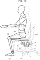
- the seat only performs a pivotal operation via the supporting post around the lower end being a fulcrum, and therefore, a seat pivotal trajectory is not accorded with a movement below the knees of the seated person, resulting in an undesirable support state in which the feet get stuck when the seat inclines forward.
- the inventors of the present application could contemplate the present invention by focusing for the first time on the following advantage that a seated person moves his/her lumbar region, gluteal region, and femoral region to the front, rear, right, and left by a predetermined dimension around a reference position being a center at which the seated person his/herself sits, and when the seat is inclined while the seat is moved horizontally during the movement and further, when the seat is operated so that a backswing force that causes the chair to return to the reference position is naturally obtained, as a result of which it is possible to improve the comfort of the seated person to make the seated person less exhausted while improving work efficiency.
- the seat supported by the above-described support mechanism can be configured not to perform a monotonous pivotal operation around a certain fulcrum close to the floor, and thus, the pivotal trajectory of the seat can be accorded with the movement below the knees of the seated person, as a result of which it is easy to realize a proper support state in which the feet do not get stuck even when inclining forward.
- the chair of the present invention when a seat surface inclines, the seat moves in a direction of the inclination, and thus, it is possible to configure a chair that extraordinarily well fits to the body movement of the seated person, and that, in view of a tendency of movement resulting from a human body structure of the seated person during sitting, can suitably support such a movement.
- a chair in which the seated person can perceive a comfortable sitting feeling even if sitting for a long time, and a high work efficiency can stably be maintained.
- a return force works which attempts to return the seat to the reference position in accordance with the movement of the seat, and thus, the seated person can perceive a pleasant feeling with a gentle motion as if sitting on a rocking chair.
- the leg includes the lifting up and down mechanism
- the seat is arranged above the lifting up and down mechanism
- the support mechanism is interposed between the lifting up and downing mechanism and the seat.
- an operation angle and an operation distance of the seat in the front-rear direction are set so as to be larger than those in the left-right direction or those in a rear direction are set to be larger than those in a front direction.
- the support mechanism includes a front-rear support unit configured to operatively support the seat in the front-rear direction and a left-right support unit configured separately from the front-rear support unit and configured to operatively support the seat in the left-right direction
- the return-force generation mechanism includes a front-rear return unit configured to generate a return force in the front-rear direction and a left-right return unit configured separately from the front-rear return unit and configured to generate a return force in the left-right direction.
- the front-rear support unit and the left-right support unit are arranged to overlap at an overlapping position in planar view.
- the front-rear support unit and the left-right support unit are arranged to overlap in an up-down direction.
- the front-rear support unit is arranged above the left-right support unit and is positioned closer to the seated person.
- the backrest is preferable to attach the backrest to the front-rear support unit so that the tilting mechanism of the backrest can be configured with a simple configuration and the backrest can follow more naturally the movement of the seated person.
- the support mechanism includes a guide surface formed along a predetermined trajectory and a follower configured to perform a relative operation following the guide surface.
- the support mechanism includes a slowing portion configured to slow an operation of the follower in accordance with its closeness to an operation end of the follower.
- the support mechanism includes a link member in which the operation end is operable along a predetermined trajectory.
- the leg includes a caster configured to rollably contact a floor surface. That is, as in Japanese Unexamined Patent Application Publication (Translation of PCT Application) No. 10-513374 , if in the chair, an element that grips the floor surface due to a frictional force during sitting contacts the floor surface, there is a problem that the person cannot move while seated. In contrary thereto, in the present invention, it is less likely that a horizontal force is exerted on the caster even if the seat is in an inclined state during sitting, and thus no other elements are needed which generate the frictional force onto the floor surface, as a result of which the seated person can move while seated when necessary.
- the support mechanism is configured to move the supporting locations to the seat to the front, rear, right, and left by combining a front support structure and a rear support structure configured to directly or indirectly support a bottom surface of the seat at least at two locations in the front-rear direction and a left support structure and a right support structure configured to directly or indirectly support the bottom surface of the seat at two locations in the left-right direction, the supporting locations being configured to draw a trajectory along which a tip side in a movement direction of the seat is downwardly inclined in accordance with the movement; and further comprises a return-force generation mechanism configured to generate, in accordance with the amount of the movement, a return force in a direction of returning the supporting locations to the seat having moved from the reference position in the front-rear or left-right direction, to the reference position.
- Examples of specific modes of an implementation include that which includes a slowing portion configured to slow an operation in accordance with its closeness to the tip side in the movement direction of the seat and that which includes a shockless unit configured to absorb a shock between members at the operation end of the seat.
- the present invention can provide a chair in which the seated person can perceive a comfortable sitting feeling even if sitting for a long time, and a high work efficiency can stably be maintained.
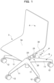
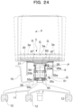
- the leg 1 includes: a leg vane 11 formed radially in plan view; a caster 12 attached to a bottom side of the leg vane 11 and rollably contacting the floor surface; a leg supporting post 13 erected on a center of the leg vane 11; a gas spring 14 being a lifting up and down mechanism mounted within the leg supporting post 13 and configured to support the seat 3 in a lifting up and down manner, a rotation support mechanism 16 configured to support, in the vicinity of an upper end of the leg supporting post 13, the seat 3 to permit horizontal rotation by allowing a rod of the gas spring 14 to relatively rotate with respect to the leg supporting post 13; and an operation lever 15 configured to adjust a vertical position of the seat 3 by pressing a push button 17 arranged at an upper end of the gas spring 14 to extend and shrink the gas spring 14.
- the seat 3 is constructed mainly of a seat main body 30 of a plate shape formed integrally with the backrest 4, where a top surface of the seat main body 30 is a seat surface 3a, and a seat receiver 31 for supporting the seat 3 from below is attached on a bottom surface side of the seat main body 30.
- the support mechanism 2 is configured to move the supporting locations to the seat 3 to the front, rear, right, and left by combining a front support structure and a rear support structure configured to directly or indirectly support the bottom surface of the seat 3 at least at two locations in the front-rear direction and a left support structure and a right support structure configured to directly or indirectly support the bottom surface of the seat 3 at two locations in the left-right direction, the supporting locations being configured to draw a trajectory along which the tip side in a movement direction of the seat 3 is downwardly inclined in accordance with the movement; and further includes a center-of-gravity movement mechanism P described later being a return-force generation mechanism configured to generate, in accordance with the amount of movement, the return force in the direction of returning the supporting locations to the seat 3 having moved from the reference position (S) in the front-rear or left-right direction, to the reference position (S).
- a configuration of the support mechanism 2 will be described specifically below.
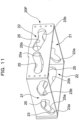
- the support mechanism 2 in the present embodiment includes guide surfaces 23a, 23b, 25a, and 25b interposed between the leg 1 and the seat 3 and formed along a predetermined trajectory for moving the seat 3 in the front-rear direction and the left-right direction and followers 24a, 24b, 26a, and 26b configured to perform a slide operation following the guide surfaces 23a, 23b, 25a, and 25b, and operatively supports the seat 3 by a relative operation of the guide surfaces 23a, 23b, 25a, and 25b and the followers 24a, 24b, 26a, and 26b.
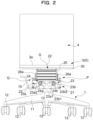
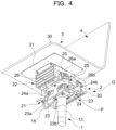
- the support mechanism 2 is configured from an upper end portion of the leg 1 to a lower end portion of the seat receiver 31. Specifically, the support mechanism 2 is configured by the upper end portion of the leg 1, the lower end portion of the seat receiver 31, and a support housing 20 interposed between the upper end portion of the leg 1 and the lower end portion of the seat receiver 31.
- a pair of left-right support units 21 in the front-rear direction configured to operatively support the seat 3 in the left-right direction is configured over the upper end portion of the leg 1 and a lower half region of the support housing 20, and a pair of front-rear support units 22 in the left-right direction configured to operatively support the seat 3 in the front-rear direction is configured over the lower end portion of the seat receiver 31 and an upper half region of the support housing 20. That is, the left-right support units 21 and the front-rear support units 22 overlap at an overlapping position in planar view are configured respectively independently as a separate body.
- the front-rear support units 22 directly supports the seat 3 configured integrally with the backrest 4, and thus, in the present embodiment, a configuration in which the backrest 4 is indirectly attached to the front-rear support unit 22 is adopted, and needless to say, a configuration in which the backrest 4 is directly attached in a region of the upper half portion of the support housing 20 shall not be precluded.
- the shockless unit R is configured which absorbs a shock so that the front follower 26a and the rear follower 26b make no contact with front-rear both end surfaces of the front-rear guide holes 25.
- the front-rear guide holes 25 may be arranged continuously and integrally.
- each of the rear follower 26b and the front follower 26a follows the upwardly inclined first regions 25a1 and 25b1, and upon further swinging, the rear follower 26b and the front follower 26a enter the second regions 25a2 and 25b2 configured with a larger inclination degree.
- the shockless unit R is formed.
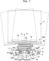
- the chair according to the present embodiment not only suitably maintains the posture of the seated person during sitting, but can also suitably support the movement of the seated person during sitting. That is, even if the seated person moves the center of gravity to the front, rear, right, and left, as long as the seat 3 has its center of gravity G located between the supporting locations arranged in the front and rear followers 26a, 26b at two locations in the front-rear direction, or as long as the seat 3 has its center of gravity G located between the left-right followers 24a and 24b or supporting locations arranged at two locations in the left-right direction, it is designed such that no large falling moment is exerted on the support mechanism 2, and thus, it is possible to reduce a need for the seated person to brace his/her feet to the floor to rest in a proper posture.
- the seat 3 supported by the above-described support mechanism 2 can be set not to perform a monotonous pivotal operation around a certain fulcrum close to the floor, and thus, the pivotal trajectory of the seat 3 can be accorded with or close to the operation below the knee of the seated person, as a result of which a proper support state is realized in which the feet do not get stuck even when inclining forward.
- the support mechanism 2 there is no problem that the seat 3 sinks down every time the seated person sits down, and there is no inconvenience caused as in the case where the lower end of the supporting post comes in contact with the floor for pivoting.
- the seat surface 3a inclines
- the seat of the chair of the present invention moves in the direction of the inclination, and thus, the chair extraordinarily well can fit to the body movement of the seated person.
- the leg 1 includes a lifting up and down mechanism having the gas spring 14, the seat 3 is arranged above the lifting up and down mechanism, and the support mechanism 2 is interposed between the lifting up and down mechanism and the seat 3, and thus, a compact configuration is realized, instead of a complicated structure in which the support mechanism 2 is merged with the lifting up and down mechanism.
- the support mechanism 2 is configured to support the seat 3 independently and operatively in each of at least the front-rear direction and left-right direction along a predetermined trajectory, and thus, each of the forward, backward, rightward, and leftward operations of the seat 3 can be smoothly performed.
- the return-force generation mechanism when the return-force generation mechanism is constructed as the center-of-gravity movement mechanism P configured to elevate the center of gravity G of the seat 3 in accordance with the operation of the seat 3 from the reference position (S), the return-force generation mechanism is realized with a simpler configuration.
- the center-of-gravity movement mechanism P with a combination of the operations by the center-of-gravity movement mechanism P and the above-described seat inclining mechanism Q, even in an operation in which the seat surface 3a is inclined forward, the seated person does not easily take a posture in which the feet of the seated person get stuck, and thus, it is possible to further improve a comfort during sitting.
- a rotation support mechanism 16 configured to support the seat 3 horizontally rotatably is provided, and thus, the movement of the seated person during work may be more suitably followed.
- the support mechanism 2 includes the front-rear support unit 22 configured to operatively support the seat in the front-rear direction and the left-right support unit 21 configured to operatively support the seat in the left-right direction, where the left-right support unit 21 is configured separately from the front-rear support unit 22.
- the return-force generation mechanism includes a front-rear return unit configured to generate a return force in the front-rear direction and a left-right return unit configured to generate a return force in the left-right direction, where the left-right return unit is configured separately from the front-rear return unit.
- the front-rear support unit 22 and the left-right support unit 21 are arranged to be layered at an overlapping position in planar view, and thus, a whole chair is compact in planar view.
- the backrest 4 is directly attached to the front-rear support unit 22, and thus, a back of the seated person is suitably supported and a more comfortable sitting feeling can be obtained.
- the support mechanism 2 includes the guide surfaces 23a, 23b, 25a, and 25b formed along a predetermined trajectory and the followers 24a, 24b, 26a, and 26b configured to perform a relative operation following the guide surfaces 23a, 23b, 25a, and 25b, and thus, a precise and stable operation of the seat 3 is realized.
- the support mechanism 2 has the slowing portion including the first regions 23a1, 23b1, 25a1, 25b1 and the second regions 23a2, 23b2, 25a2, and 25b2 configured to slow the operation of the followers 24a, 24b, 26a, and 26b toward the operation end of the followers 24a, 24b, 26a, and 26b, and thus, it is possible to effectively avoid a situation in which the seated person is given an undesirable "fear" or discomfort due to an unintended abrupt operation of the seat 3.
- the support mechanism includes the shockless unit R configured to avoid a collision between the end of the guide surfaces 23a, 23b, 25a, and 25b and the followers 24a, 24b, 26a, and 26b at the operation end, and thus, an undesirable shock and noise due to the abrupt operation of the seat 3 is not inflicted on the seated person.
- the leg 1 includes the casters 12, and thus, it is possible to prevent the chair from easily moving even if the seat 3 operates forward, rearward, rightward, or leftward while the seated person can move together with the chair while being seated when required. This eliminates an element for gripping the floor surface by frictional force to swing the seat 3 during sitting, unlike in Japanese Unexamined Patent Application Publication (Translation of PCT Application) No. 10-513374.
- the support mechanism 2 in order to realize the above-described behavior of the chair 3 with the support mechanism 2 alone, is configured to move the supporting locations to the seat 3 to the front, rear, right, and left by combining the front support structure including the front guide surface 25a and the front follower 26a and the rear support structure including the rear guide surface 25b and the rear follower 26b, configured to directly or indirectly support the bottom surface of the seat 3 at least at two locations in the front-rear direction, and the left support structure including the left guide surface 23a and the left follower 24a and the right support structure including the right guide surface 23b and the right follower 24b, configured to directly or indirectly support the bottom surface of the seat 3 at two locations in the left-right direction, the supporting locations being configured to draw a trajectory along which the tip side in a movement direction of the seat 3 is downwardly inclined in accordance with the movement, and the support mechanism 2 further includes a return-force generation mechanism configured to generate, in accordance with the amount of movement, the return force in the direction of returning the supporting
- the "supporting locations" are naturally contact points or contact portions between the front, rear, right, and left guide holes 23a, 23b, 25a, and 25b and the front, rear, right, and left followers 24a, 24b, 26a, and 26b.
- the contact points or contact portions may change vertically. Particularly, if the center of gravity of the seated person is not between the supporting locations, the contact points or the contact portions may change vertically.
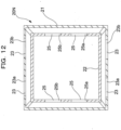
- a support housing 20F is illustrated instead of the support housing 20 disclosed in the above-described embodiment. That is, in the above-described embodiment, in order that the left-right support unit 21 and the front-rear support unit 22 are positioned by the support housing 20 at an overlapping position in planar view, each portion configuring the front-rear support unit 22 and the left-right support unit 21 is configured to be layered in an up-down direction; however, the support housing 20F is configured so that the front-rear support unit 22 and the left-right support unit 21 overlap in the up-down direction. Needless to say, in the modification, a configuration of a portion in the vicinity of the upper end of the leg 1 of the chair and a portion in the vicinity of the seat receiver 31 may be accordingly changed in accordance with a shape of the support housing 20F.
- Fig. 12 illustrates a schematic plane cross-section of a support housing 20N used instead of the support housing 20 disclosed in the above-described embodiment. That is, in the above-described embodiment, in order that the left-right support unit 21 and the front-rear support unit 22 are positioned by the support housing 20 at an overlapping position in planar view, each portion configuring the front-rear support unit 22 and the left-right support unit 21 is configured to be layered in the up-down direction; however, the support housing 20N is configured so that the front-rear support unit 22 and the left-right support unit 21 are nested (the front-rear support unit 22 being inside and the left-right support unit 21 being outside respectively) to overlap in both planar view and front view (not illustrated).
- a configuration of a portion in the vicinity of the upper end of the leg 1 of the chair and a portion in the vicinity of the seat receiver 31 may be accordingly changed in accordance with a shape of the support housing 20N.
- a chair according to a second embodiment of the present invention may be suitably utilized as an office rotating chair, similarly to that in the first embodiment described above.
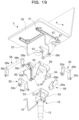
- a support mechanism 5 interposed between the leg 1 and the seat 3 is arranged below the seat 3, is configured to movably support the seat 3, at least at two locations in the front-rear direction and two locations in the left-right direction, along a predetermined trajectory, includes a seat inclining mechanism Q being a seat inclining function configured to downwardly incline the tip side in a movement direction of the seat 3 in accordance with movement of the seat 3, and further includes a return-force generation mechanism configured to generate the return force in the direction of returning the seat 3 having moved from the reference position (S) in the front-rear or left-right direction, to the reference position (S).
- the support mechanism 5 is configured as a suspension support mechanism different from that in the above-described embodiment, and consequently, the return force generating mechanism and the seat inclining mechanism Q are configured in a different mode.
- the chair according to the present invention is provided with the support mechanism 5 as the suspension support mechanism configured to operatively support the seat 3, at least in the front-rear direction and in the right-left direction, along a predetermined trajectory by suspending a part of the seat 3 from a part of the leg 1 from above.
- the support mechanism 5 as the suspension support mechanism configured to operatively support the seat 3, at least in the front-rear direction and in the right-left direction, along a predetermined trajectory by suspending a part of the seat 3 from a part of the leg 1 from above.
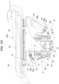
- the support mechanism 5 is interposed between the leg 1 and the seat 3, and applies a link mechanism having link members 55, 58, and 59 extending in the up-down direction so that the seat 3 can be operatively supported along a predetermined trajectory along which the seat 3 is operated in the front-rear direction and in the right-left direction.
- the support mechanism 5 is configured by the upper end portion of the leg 1, the lower end portion of the seat receiver 31, and a swing support body 50 interposed between the upper end portion of the leg 1 and the lower end portion of the seat receiver 31.
- the support mechanism 5 includes a left-right support unit 51 configured to operatively support the seat 3 in the right-left direction over the upper end portion of the leg 1 and the lower region of the swing support body 50, and a front-rear support unit 52 configured to operatively support the seat 3 in the front-rear direction over the lower end portion of the seat receiver 31 and the upper region of the swing support body 50. That is, the left-right support unit 51 and the front-rear support unit 52 overlap in the up-down direction at an overlapping position in planar view and are independently configured as a separate body at a position surrounding the leg supporting post 13 as the center in the plan view of the seat 3.
- the front-rear support unit 52 directly supports the seat 3 integrally configured with the backrest 4, and thus, in the present embodiment, configuration is that the backrest 4 is indirectly attached to the front-rear support unit 52; however, needless to say, configuration that the backrest 4 is attached on the upper half region of the swing support body 50 shall not be precluded.
- the left-right support unit 51 includes a left-right swing unit 54 formed in a lower half region of the swing support body 50, a left-right suspension unit 53 configured to suspend and support the left-right swing unit 54 formed on the upper end of the leg 1, and a pair of left-right links 55 pivotally attached to the left-right swing unit 54 and the left-right suspension unit 53.
- the left-right link 55 includes a link main body 55a extending in the up-down direction, a suspension shaft 55b configured at the upper end of the link main body 55a to be pivotally attached onto the left-right suspension unit 53, and a swing shaft 55c configured at a lower end of the link main body 55a to be pivotally attached onto the left-right swing unit 54.
- the pair of left-right links 55 is set so that a distance between the swing shafts 55c provided at the lower end of the left-right link 55 is shorter than a distance between the suspension shafts 55b provided at the upper end of the left-right link 55.
- the right support structure and the left support structure are configured by the supporting location of the left-right link 55 and the left-right link 55.
- the front-rear support unit 52 includes a front-rear swing unit 57 formed at a lower end of the seat receiver 31, a front-rear suspension unit 56 formed in an upper half region of the swing support body 50, the front-rear suspension unit 56 being for suspending and supporting the front-rear swing unit 57, and a front link 58 and a rear link 59 pivotally attached onto the front-rear swing unit 57 and the front-rear suspension unit 56.
- the front link 58 includes a front link main body 58a extending in the up-down direction, a front suspension shaft 58b configured at an upper end of the front link main body 58a, the front suspension shaft 58b being pivotally attached at a front side position of the front-rear suspension unit 56, and a front swing shaft 58c configured at a lower end of the front link main body 58a, the front swing shaft 58c being pivotally attached at a front side position of the front-rear swing unit 57.
- the rear link 59 includes a rear link main body 59a extending in the up-down direction, a rear suspension shaft 59b configured at an upper end of the rear link main body 59a, the rear suspension shaft 59b being pivotally attached to the front-rear suspension unit 56, and a rear swing shaft 59c configured at a lower end of the rear link main body 59a, the rear swing shaft 59c being pivotally attached to the front-rear swing unit 57.
- the front link 58 and the rear link 59 are set so that a distance between the front swing shaft 58c and the rear swing shaft 59c provided at the lower end of the front link 58 and the rear link 59 is shorter than a distance between the front suspension shaft 58b and the rear suspension shaft 59b provided at the upper end of the front link 58 and the rear link 59.
- the front support structure is configured by the front link 58 and the location at which the front link 58 is supported
- the rear support structure is configured by the rear link 59 and the location at which the rear link 59 is supported.
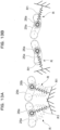
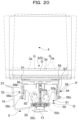
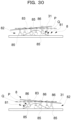
- Fig. 20 illustrates a behavior when the seat 3 operates in the right-left direction from the predetermined reference position (S) at which the seat 3 rests by its own weight.
- the seat surface 3a operates rightward and leftward by the left-right support unit 51, its operation is against the gravity.
- the position of the center of gravity G of the seat surface 3a rises from the reference position (S) indicated by a solid line.
- a return force exerted by the gravity in a direction of returning the seat 3 to the reference position (S) is spontaneously applied to the seat 3.
- the left-right link 55 is the left-right return unit, out of the return-force generation mechanism, configured to generate the return force in the right-left direction, and functions as the center-of-gravity movement mechanism P configured to elevate the center of gravity G of the seat 3 when the seat 3 operates from the reference position (S).
- the seat surface 3a operating rightward and leftward in Fig. 20 is in a posture in which the operation tip side is descended.
- the distance between the swing shafts 55c provided at the lower end of the left-right link 55 is set to be shorter than the distance between the suspension shafts 55b provided at the upper end of the left-right link 55.
- the left-right link 55 also functions as the seat inclining mechanism Q.
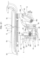
- Fig. 21 illustrates a behavior when the seat 3 operates in the front-rear direction from the predetermined reference position (S) at which the seat 3 rests by its own weight.
- the seat surface 3a operates forward and rearward by the front-rear support unit 52, its operation is against the gravity.
- the position of the center of gravity G of the seat surface 3a elevates from the reference position (S) indicated by the solid line. Further, at this time, a return force exerted by the gravity in a direction of returning the seat 3 to the reference position (S) is spontaneously applied to the seat 3.
- the front link 58 and the rear link 59 correspond to the front-rear return unit, out of the return-force generation mechanism, configured to generate the return force in the front-rear direction, and functions as the center-of-gravity movement mechanism P configured to elevate the center of gravity G of the seat 3 in accordance with the operation of the seat 3 from the reference position (S).
- the seat surface 3a operating forward and rearward takes a posture in which the operation tip side is descended.
- the distance between the front swing shafts 58c and the rear swing shaft 59c provided at the lower end of the front link 58 and the rear link 59 is set to be shorter than the distance between the front suspension shaft 58b and the rear suspension shaft 59b provided at the upper end of the front link 58 and the rear link 59. That is, in the present embodiment, the front link 58 and the rear link 59 also function as the seat inclining mechanism Q.
- the leg 1 is similar in configuration to the above-described embodiments other than the configuration in which the rotation support mechanism 16 as a part of the leg 1 configured to rotatably support the seat 3 is not provided, and thus, the description will be omitted.
- the chair according to the present embodiment is similar to the above-described embodiments in that the support mechanism is configured across the upper end portion of the leg 1 to the seat receiver 31.
- the return force generating mechanism and the seat inclining mechanism Q are also configured in a different mode.
- a guide support mechanism 8 is provided which can serve a role as a rotation support mechanism configured to rotatably support the seat 3 in the horizontal direction, in addition to a role of the support mechanism providing the same effect as in the above-described embodiments.
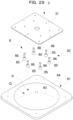
- the guide support mechanism 8 in order to operatively support the seat 3 along a predetermined trajectory, interposed between the leg 1 and the seat 3, along which the seat is operated in the front-rear direction and left-right direction, applies a configuration having a guide board 81 having a guide curved surface 83 of substantially conical shape or truncated cone shape and a sliding contact follower 82 that can slide on the guide curved surface 83 in any direction.
- This guide support mechanism 8 is configured to be interposed between the upper end portion of the leg 1 and the lower end portion of the seat receiver 31.
- the shape of the guide curved surface 83 has a curved surface shape such that the degree of inclination gradually becomes larger as being closer to the center of the guide board 81 from the vicinity of an outer periphery thereof.
- the center of the guide board 81 is configured in a planar form; however, the sliding contact follower 82 is set to not slide over the planar portion.
- the sliding contact follower 82 is arranged with respect to the seat receiver 31 at six locations being at least four or more locations allowing for a stable self-standing, so that each location corresponds to a relative position corresponding to each vertex of an equilateral hexagon in planar view.
- the sliding contact follower 82 is arranged at a relative position which can be arranged in equal intervals on the outline of the exact circle.
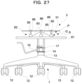
- the sliding contact follower 82 includes a follower main body 85 having a substantially spherical shape slidingly contacting the guide curved surface 83 and a seat supporting post 86 of which the lower end portion is supported by the follower main body 85 and of which the upper end portion is fixed to the seat receiver 31.
- Fig. 27 illustrates the seat receiver 31 only
- Fig. 30 illustrates a behavior of the seat receiver 31 when the seat 3 operates from a predetermined reference position (S) at which the seat 3 rests by its own weight into any direction.
- the guide curved surface 83 being a guide surface is provided so that there are always, of the six sliding contact followers 82, some sliding contact followers 82 ascending and the other sliding contact followers 82 descending, during the operation of the seat.
- the position of the center of gravity of the seat receiver 31 rises from the reference position (S). Further, at this time, a return force exerted by the gravity in a direction of returning the seat 3 to the reference position (S) is spontaneously applied to the seat 3. That is, in the present embodiment, the guide curved surface 83 and the sliding contact follower 82 are the return-force generation mechanism and function as the center-of-gravity movement mechanism P configured to elevate the center of gravity G of the seat 3 in accordance with the operation of the seat 3 from the reference position (S). In addition, the seat receiver 31 that has operated is in a posture in which the operation tip side is descended. As described above, this results from the feature that the guide curved surface 83 is in a substantially truncated cone shape. That is, in the present embodiment, the guide curved surface 83 also functions as the seat inclining mechanism Q.
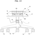
- each of the six sliding contact followers 82 is firmly fixed to the seat receiver 31; however, as illustrated in Fig. 31 , needless to say, a spring 87 may be separately arranged in the sliding contact follower 82.
- the sliding contact follower 82 further includes a spring 87 interposed between the seat supporting post 86 and the seat receiver 31.
- a pressure coil spring of which the upper end portion is fixed to the seat receiver 31 side and the lower end portion is fixed to the upper end portion of the seat supporting post 86, is installed. This results in reducing a shock applied to the seated person during sitting being relieved, and contributes to smoother operation of the seat 3.
- the number of the sliding contact followers 82 is not limited to six, and seven or more sliding contact followers 82 may be arranged concentrically. It is noted that in the modification, 18 sliding contact followers 82 are arranged concentrically.
- the guide surface is the integrally formed guide curved surface 83
- a plurality of followers or the sliding contact followers 82 can freely contact slidingly along the guide curved surface 83 in any direction of the front and rear directions and the left and right directions, that is, at least at two locations in a front-rear direction and two locations in a left-right direction, in any direction
- a smooth operation of the seat 3 can be realized by configuring so that the guide curved surface 83 being a guide surface has a substantially conical shape.
- the sliding contact follower 82 when it is so configured that the sliding contact follower 82 always contacts the guide curved surface 83 at three or more locations, the sliding contact follower 82 stably contacts the guide curved surface 83, as a result of which it is possible to stably support the seat receiver 31 and the seat 3 as well.
- the illustration of the backrest 4 is omitted to clarify the configuration of the seat 3 and the position of the seat surface 3a; however, it is not intended to exclude assembling of the backrest 4.
- the leg 1 has a configuration similar to that in the above-described embodiments, and thus, description will be omitted.
- the chair according to the present embodiment is similar to that in the embodiments described above in that the support mechanism is configured across the upper end portion of the leg 1 to the lower end portion of the seat receiver 31.
- the return-force generation mechanism and the seat inclining mechanism Q are configured in a different mode.
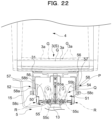
- the chair according to the present embodiment is common to the above-described second embodiment in that the suspension support mechanism configured to operatively support the seat 3 at least in the front-rear direction and the left-right direction along a predetermined trajectory by suspending a part of the seat 3 from a part of the leg 1 from above is the link mechanism including the link member extending in the up-down direction.
- the chair according to the present embodiment is different from the suspension support mechanism according to the above-described embodiment in that the link member is a both-end universal joint 72 being a universal joint of which the both ends are operatively supported both in the front-rear direction and in the left-right direction.
- the seat 3 when a joint support mechanism 7 allowing the seat 3 and the leg 1 to be coupled via the both-end universal joints 72 is provided, the seat 3 is configured to be operable in the front-rear direction and the left-right direction.
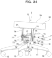
- the joint support mechanism 7 is interposed between the leg 1 and the seat 3, and applies a link mechanism having, for convenience in Fig 32 to Fig. 34 , three both-end universal joints 72 being link members extending in the up-down direction so that the seat 3 is supported at least at two locations in the front-rear direction and two locations in the left-right direction and the seat 3 can be operatively supported along a predetermined trajectory along which the seat 3 is operated.
- the joint support mechanism 7 includes a suspension board 71 provided in an upper end portion of the leg 1, the both-end universal joints 72 of which the upper end portion is connected to the suspension board 71, a swing board 73 connected to a lower end portion of the both-end universal joints 72, and a seat support post 74 erected on the swing board 73 and configured to support the seat 3 at a height position higher than the suspension board 71.
Landscapes
- Health & Medical Sciences (AREA)
- Dentistry (AREA)
- General Health & Medical Sciences (AREA)
- Chairs Characterized By Structure (AREA)
- Chairs For Special Purposes, Such As Reclining Chairs (AREA)
Claims (17)
- Stuhl, der aufweist:ein Bein (1), das an einer Bodenfläche aufgerichtet ist;einen Sitz (3), der über dem Bein (1) angeordnet ist; undeinen Stützmechanismus (2; 5; 6; 7; 8), der zwischen dem Bein (1) und dem Sitz (3) in Zwischenlage ist, wobeider Stützmechanismus (2; 5; 6; 7; 8) unter dem Sitz (3) angeordnet ist und dazu gestaltet ist, den Sitz (3) bewegbar zu stützen, mindestens an zwei Stellen in einer Vorne-Hinten-Richtung und zwei Stellen in einer Links-Rechts-Richtung, entlang einer vorbestimmten Trajektorie,der Stützmechanismus (2; 5; 6; 7; 8) aufweist:einen Rückstellkrafterzeugungsmechanismus (P), der dazu gestaltet ist, in Übereinstimmung mit einem Bewegungsbetrag eine Rückstellkraft in einer Richtung eines Rückstellens des Sitzes (3), der sich in einer Vorne-Hinten- oder Links-Rechts-Richtung von einer Referenzposition (S) bewegt hat, zu der Referenzposition (S) zu erzeugen,dadurch gekennzeichnet, dassder Stützmechanismus (2; 5; 6; 7; 8) ferner eine Sitzneigungsfunktion aufweist, die derart gestaltet ist, dass, wenn sich eine Sitzfläche (3a) neigt, der Sitz (3) sich in einer Richtung der Neigung und zum Abwärtsneigen einer Spitzenseite in einer Bewegungsrichtung des Sitzes (3) in Übereinstimmung mit einer Bewegung des Sitzes (3) von einer vorbestimmten Referenzposition (S) bewegt.
- Stuhl gemäß Anspruch 1, wobei das Bein (1) einen Hebe-/Senkmechanismus aufweist, der Sitz (3) über dem Hebe-/Senkmechanismus angeordnet ist und der Stützmechanismus (2; 5; 6; 7; 8) zwischen dem Hebe-/Senkmechanismus und dem Sitz (3) in Zwischenlage ist.
- Stuhl gemäß Anspruch 1 oder 2, wobei der Stützmechanismus (2; 5; 6; 7; 8) den Sitz (3) unabhängig und betätigbar in jeder von zumindest der Vorne-Hinten-Richtung und der Links-Rechts-Richtung stützt, entlang der vorbestimmten Trajektorie.
- Stuhl gemäß einem der Ansprüche 1 bis 3, wobei ein Betätigungswinkel und eine Betätigungsentfernung des Sitzes (3) in der Vorne-Hinten-Richtung so festgelegt sind, dass sie größer sind als die in der Links-Rechts-Richtung.
- Stuhl gemäß Anspruch 4, wobei der Betätigungswinkel des Sitzes (3) in einer Hinten-Richtung festgelegt ist, dass er größer ist als der in einer Vorne-Richtung.
- Stuhl gemäß einem der Ansprüche 1 bis 5, wobei der Rückstellkrafterzeugungsmechanismus (P) ein Schwerkraftzentrumsbewegungsmechanismus ist, der dazu gestaltet ist, ein Schwerkraftzentrum (G) des Sitzes (3) in Übereinstimmung mit einer Betätigung des Sitzes (3) von der Referenzposition (S) anzuheben.
- Stuhl gemäß einem der Ansprüche 1 bis 6, der einen Drehstützmechanismus (16) aufweist, der dazu gestaltet ist, den Sitz (3) horizontal drehbar bezüglich des Beins (1) zu stützen.
- Stuhl gemäß einem der Ansprüche 1 bis 7, wobei der Stützmechanismus (2; 5; 6; 7; 8) eine Vorne-Hinten-Stützeinheit (22, 52), die dazu gestaltet ist, den Sitz (3) in einer Vorne-Hinten-Richtung betätigbar zu stützen, und eine Links-Rechts-Stützeinheit (21; 51) aufweist, die getrennt von der Vorne-Hinten-Stützeinheit (22; 52) gestaltet ist, wobei die Links-Rechts-Stützeinheit (21; 51) dazu gestaltet ist, den Sitz (3) in einer Links-Rechts-Richtung betätigbar zu stützen; und
der Rückstellkrafterzeugungsmechanismus (P) eine Vorne-Hinten-Rückstelleinheit, die dazu gestaltet ist, eine Rückstellkraft in einer Vorne-Hinten-Richtung zu erzeugen, und eine Links-Rechts-Rückstelleinheit aufweist, die getrennt von der Vorne-Hinten-Rückstelleinheit gestaltet ist, wobei die Links-Rechts-Rückstelleinheit dazu gestaltet ist, eine Rückstellkraft in einer Links-Rechts-Richtung zu erzeugen. - Stuhl gemäß Anspruch 8, wobei die Vorne-Hinten-Stützeinheit (22; 52) und die Links-Rechts-Stützeinheit (21; 51) sich an einer Überlappungsposition in einer Draufsicht überlappen.
- Stuhl gemäß Anspruch 8, wobei die Vorne-Hinten-Stützeinheit (22; 52) und die Links-Rechts-Stützeinheit (21; 51) dazu angeordnet sind, sich in einer Oben-Unten-Richtung zu überlappen.
- Stuhl gemäß einem der Ansprüche 8 bis 10, wobei die Vorne-Hinten-Stützeinheit (22; 52) über der Links-Rechts-Stützeinheit (21; 51) angeordnet ist.
- Stuhl gemäß einem der Ansprüche 8 bis 11, wobei eine Rückenlehne (4) an der Vorne-Hinten-Stützeinheit (22; 52) angebracht ist.
- Stuhl gemäß einem der Ansprüche 1 bis 12, wobei der Stützmechanismus (2; 6) eine Führungsfläche (23a, 23b, 25a, 25b), die entlang der vorbestimmten Trajektorie ausgebildet ist, und eine Nachlaufeinrichtung (24a, 24b, 26a, 26b) aufweist, die dazu gestaltet ist, einen der Führungsfläche folgenden Relativbetrieb durchzuführen.
- Stuhl gemäß Anspruch 13, wobei der Stützmechanismus (2; 6) einen Verlangsamungsabschnitt aufweist, der dazu gestaltet ist, eine Betätigung der Nachlaufeinrichtung in Übereinstimmung mit seiner Nähe zu einem Betätigungsende der Nachlaufeinrichtung (24a, 24b, 26a, 26b) zu verlangsamen.
- Stuhl gemäß Anspruch 13 oder 14, wobei der Stützmechanismus (2; 6) eine Stoßloseinheit (R) aufweist, die dazu gestaltet ist, einen Stoß zu absorbieren, der durch eine Kollision zwischen einem Ende einer Führungsfläche (23a, 23b, 25a, 25b) und einer Nachlaufeinrichtung (24a, 24b, 26a, 26b) an einem Betätigungsende verursacht wird.
- Stuhl gemäß einem der Ansprüche 1 bis 15, wobei der Stützmechanismus (5; 6; 7) ein Verknüpfungselement (55, 58, 59; 72) aufweist, das es einem Betätigungsende ermöglicht, entlang der vorbestimmten Trajektorie zu betätigen.
- Stuhl gemäß einem der Ansprüche 1 bis 16, wobei das Bein (1) eine Rolle (12) aufweist, die dazu gestaltet ist, eine Bodenfläche rollbar zu berühren.
Priority Applications (2)
| Application Number | Priority Date | Filing Date | Title |
|---|---|---|---|
| EP20166183.2A EP3708033A1 (de) | 2016-02-23 | 2016-02-23 | Stuhl und sitzträgermechanismus |
| EP20166180.8A EP3708032A1 (de) | 2016-02-23 | 2016-02-23 | Stuhl und sitzträgermechanismus |
Applications Claiming Priority (1)
| Application Number | Priority Date | Filing Date | Title |
|---|---|---|---|
| PCT/JP2016/055313 WO2017145271A1 (ja) | 2016-02-23 | 2016-02-23 | 椅子及び座の支持機構 |
Related Child Applications (4)
| Application Number | Title | Priority Date | Filing Date |
|---|---|---|---|
| EP20166183.2A Division EP3708033A1 (de) | 2016-02-23 | 2016-02-23 | Stuhl und sitzträgermechanismus |
| EP20166183.2A Division-Into EP3708033A1 (de) | 2016-02-23 | 2016-02-23 | Stuhl und sitzträgermechanismus |
| EP20166180.8A Division EP3708032A1 (de) | 2016-02-23 | 2016-02-23 | Stuhl und sitzträgermechanismus |
| EP20166180.8A Division-Into EP3708032A1 (de) | 2016-02-23 | 2016-02-23 | Stuhl und sitzträgermechanismus |
Publications (3)
| Publication Number | Publication Date |
|---|---|
| EP3420853A1 EP3420853A1 (de) | 2019-01-02 |
| EP3420853A4 EP3420853A4 (de) | 2019-10-16 |
| EP3420853B1 true EP3420853B1 (de) | 2025-07-09 |
Family
ID=59685943
Family Applications (3)
| Application Number | Title | Priority Date | Filing Date |
|---|---|---|---|
| EP20166183.2A Pending EP3708033A1 (de) | 2016-02-23 | 2016-02-23 | Stuhl und sitzträgermechanismus |
| EP16891428.1A Active EP3420853B1 (de) | 2016-02-23 | 2016-02-23 | Stuhl und sitzträgermechanismus |
| EP20166180.8A Pending EP3708032A1 (de) | 2016-02-23 | 2016-02-23 | Stuhl und sitzträgermechanismus |
Family Applications Before (1)
| Application Number | Title | Priority Date | Filing Date |
|---|---|---|---|
| EP20166183.2A Pending EP3708033A1 (de) | 2016-02-23 | 2016-02-23 | Stuhl und sitzträgermechanismus |
Family Applications After (1)
| Application Number | Title | Priority Date | Filing Date |
|---|---|---|---|
| EP20166180.8A Pending EP3708032A1 (de) | 2016-02-23 | 2016-02-23 | Stuhl und sitzträgermechanismus |
Country Status (6)
| Country | Link |
|---|---|
| US (1) | US10881208B2 (de) |
| EP (3) | EP3708033A1 (de) |
| JP (1) | JP6797890B2 (de) |
| CN (3) | CN108430270B (de) |
| CA (1) | CA3009482C (de) |
| WO (1) | WO2017145271A1 (de) |
Families Citing this family (24)
| Publication number | Priority date | Publication date | Assignee | Title |
|---|---|---|---|---|
| EP3708033A1 (de) | 2016-02-23 | 2020-09-16 | Kokuyo Co., Ltd. | Stuhl und sitzträgermechanismus |
| CA3025252C (en) * | 2016-06-20 | 2022-01-04 | Kokuyo Co., Ltd. | Chair and seat support mechanism |
| CA3025250C (en) * | 2016-06-20 | 2022-01-04 | Kokuyo Co., Ltd. | Chair and seat support mechanism |
| JP6785644B2 (ja) * | 2016-12-20 | 2020-11-18 | コクヨ株式会社 | 椅子及び椅子のカバー部材 |
| EP3560384B1 (de) * | 2016-12-20 | 2023-03-29 | Kokuyo Co., Ltd. | Stuhl |
| JP6770585B2 (ja) * | 2016-12-20 | 2020-10-14 | コクヨ株式会社 | 椅子 |
| EP3560385B1 (de) * | 2016-12-20 | 2021-08-25 | Kokuyo Co., Ltd. | Stuhl und stuhlabdeckelement |
| JP6978433B2 (ja) * | 2016-12-21 | 2021-12-08 | コクヨ株式会社 | 椅子 |
| IT201700031748A1 (it) * | 2017-03-22 | 2018-09-22 | Co Fe Mo Ind S R L | Meccanismo di articolazione per sedie |
| JP6900478B2 (ja) * | 2017-06-20 | 2021-07-07 | コクヨ株式会社 | 椅子 |
| US11006754B2 (en) | 2018-04-12 | 2021-05-18 | American Leather Operations, Llc | Motion chair |
| JP7270341B2 (ja) * | 2018-06-06 | 2023-05-10 | コクヨ株式会社 | 椅子の管理システム及び管理プログラム |
| WO2020079840A1 (ja) | 2018-10-19 | 2020-04-23 | コクヨ株式会社 | 椅子 |
| AT522122B1 (de) * | 2019-02-14 | 2020-11-15 | Sebastian Priestersberger | Sitzanordnung |
| KR102013301B1 (ko) * | 2019-03-18 | 2019-10-21 | (주)퍼맥스 | 의자용 시트 지지장치 |
| WO2020188574A1 (en) * | 2019-03-20 | 2020-09-24 | Ararat Technical Business Ltd. | Active sitting mechanism |
| JP7764461B2 (ja) * | 2020-07-22 | 2025-11-05 | フォームウェイ ファーニチャー リミティド | 椅子 |
| US11577839B2 (en) * | 2020-08-05 | 2023-02-14 | Ami Industries, Inc. | Side to side tilting aircraft seat mechanism |
| US11229291B1 (en) * | 2021-05-04 | 2022-01-25 | Michael David Collier | Ergonomic motion chair |
| US11825949B2 (en) | 2021-05-04 | 2023-11-28 | Michael David Collier | Ergonomic motion chair |
| JP7571678B2 (ja) | 2021-06-29 | 2024-10-23 | トヨタ自動車株式会社 | 足漕ぎ運動システム |
| JP7484829B2 (ja) * | 2021-06-29 | 2024-05-16 | トヨタ自動車株式会社 | 椅子 |
| US12427650B2 (en) * | 2021-07-08 | 2025-09-30 | Bear Robotics, Inc. | Support assembly |
| USD1053646S1 (en) | 2022-05-23 | 2024-12-10 | Michael David Collier | Chair with seatback |
Citations (1)
| Publication number | Priority date | Publication date | Assignee | Title |
|---|---|---|---|---|
| WO2009127061A1 (en) * | 2008-04-18 | 2009-10-22 | 2171584 Ontario Inc. | Hydraulic adjustable seat |
Family Cites Families (68)
| Publication number | Priority date | Publication date | Assignee | Title |
|---|---|---|---|---|
| US465719A (en) * | 1891-12-22 | Rocking-chair | ||
| FR958120A (de) * | 1950-03-03 | |||
| GB191029969A (en) * | 1910-12-24 | 1911-10-19 | Frederick John Gay | Chairs or Seats. |
| US3873054A (en) * | 1973-04-23 | 1975-03-25 | Burchfield And Turner Enterpri | Adjustably positionable seat support |
| DE7731339U1 (de) * | 1977-10-11 | 1978-01-26 | Fa. Willibald Grammer, 8450 Amberg | Fahrzeugsitz |
| DE3033781C2 (de) * | 1980-09-09 | 1985-08-01 | Wieners, Rudolf, 4790 Paderborn | Sitzmöbel |
| GB2119639A (en) * | 1982-05-12 | 1983-11-23 | Ring Mekanikk As | Tilting mechanism for a chair |
| US4575151A (en) * | 1983-09-13 | 1986-03-11 | Maridyne, Inc. | Chair tilting mechanism |
| NL8601457A (nl) * | 1986-06-05 | 1988-01-04 | Huka Bv Developments | Rolstoel met kantelbaar zitgedeelte. |
| JPH01297009A (ja) * | 1987-12-28 | 1989-11-30 | Isao Hosoe | 人間工学的椅子の座面 |
| DE9115439U1 (de) * | 1991-12-12 | 1992-05-07 | Pürner, Christoph, 8590 Marktredwitz | Aufhängevorrichtung für ein Sitz- oder Ruhemöbel |
| JPH07139U (ja) | 1992-03-13 | 1995-01-06 | 進 笹津 | 椅子の座部の揺動装置 |
| DE4210097C2 (de) | 1992-03-27 | 2000-05-31 | Josef Gloeckl | Aktivdynamische Sitzvorrichtung |
| DE4235435A1 (de) * | 1992-10-21 | 1994-04-28 | Martin Steifensand Sitzmoebel | Sitzträger für Sitzmöbel |
| US5409295A (en) * | 1993-05-25 | 1995-04-25 | Omniflex Specialties | Omnidirectional tilting mechanism |
| CN2218482Y (zh) * | 1994-09-10 | 1996-01-31 | 刘琪男 | 座椅的椅背倾斜摇摆结构 |
| DE19504121A1 (de) | 1995-02-08 | 1996-08-14 | Josef Gloeckl | Pendelhocker mit zentral unter der Sitzfläche angeordneter Kontakteinrichtung |
| DE29700437U1 (de) * | 1996-07-23 | 1997-11-27 | Fritz Becker KG, 33034 Brakel | Bewegungsstuhl |
| DE19654500C1 (de) * | 1996-12-18 | 1998-03-12 | Ulrich Dipl Ing Huber | Anpaßbarer Rahmenträger mit dreiachsiger Bewegunsfreiheit für Liege- und Sitzmöbel |
| DE19915003A1 (de) * | 1999-04-01 | 2000-10-05 | Michael Stips | Sitzvorrichtung und Verfahren zu ihrer Steuerung |
| DE29910620U1 (de) * | 1999-06-17 | 2000-10-19 | König + Neurath AG, 61184 Karben | Stuhl, insbesondere Bürostuhl |
| DE50111943D1 (de) * | 2000-10-12 | 2007-03-15 | Vitra Patente Ag | Lagerung für einen Sitz |
| JP2003038282A (ja) * | 2001-08-01 | 2003-02-12 | Kokuyo Co Ltd | 傾動椅子 |
| JP3936166B2 (ja) * | 2001-10-29 | 2007-06-27 | 株式会社タチエス | 車両用シート構造 |
| JP2004008440A (ja) * | 2002-06-06 | 2004-01-15 | Fuji Sogyo:Kk | 水平維持装置 |
| US6869142B2 (en) * | 2002-09-12 | 2005-03-22 | Steelcase Development Corporation | Seating unit having motion control |
| JP4580468B2 (ja) * | 2004-02-12 | 2010-11-10 | 株式会社エーエス | 支持構造体 |
| US7380881B2 (en) * | 2004-06-15 | 2008-06-03 | Freed William L | Ergonomically responsive chair |
| JP3920282B2 (ja) * | 2004-07-09 | 2007-05-30 | 信義 金子 | 健康椅子 |
| JP2006204700A (ja) * | 2005-01-31 | 2006-08-10 | Kokuyo Co Ltd | 椅子 |
| KR20050046704A (ko) * | 2005-04-27 | 2005-05-18 | 이종욱 | 흔들 벤치 |
| JP4989804B2 (ja) * | 2005-05-23 | 2012-08-01 | プラス株式会社 | ロッキング機能付高さ調節椅子 |
| DE102006021439A1 (de) * | 2005-07-21 | 2007-02-22 | Neubert, Frank, Dipl.-Designer | Stuhl, insbesondere Bürostuhl und Gelenkvorrichtung für einen Stuhl |
| JP4735966B2 (ja) * | 2005-11-11 | 2011-07-27 | コクヨ株式会社 | 背支持装置、座支持装置及び椅子 |
| US8439442B2 (en) * | 2006-09-29 | 2013-05-14 | Corewerks, Inc. | Method and apparatus to enhance proprioception and core health of the human body |
| JP2008301998A (ja) * | 2007-06-07 | 2008-12-18 | Tokai Kinzoku Kogyo Kk | 棚付き椅子 |
| JP2009072292A (ja) * | 2007-09-19 | 2009-04-09 | Yukie Takahashi | 着座具及び椅子 |
| US10383445B2 (en) * | 2007-10-10 | 2019-08-20 | Hector Serber | Dynamically balanced seat assembly having independently and arcuately movable backrest and method |
| DE202007016488U1 (de) | 2007-11-06 | 2008-02-21 | Prömm, Felix Tobias | Sitzvorrichtung |
| JP3144593U (ja) * | 2008-06-24 | 2008-09-04 | 株式会社サイエンス・ロード | 揺動椅子 |
| CN201263515Y (zh) * | 2008-09-28 | 2009-07-01 | 陈敏 | 椅子 |
| JP5479833B2 (ja) * | 2009-09-30 | 2014-04-23 | 株式会社岡村製作所 | 椅子 |
| JP5085635B2 (ja) * | 2009-12-28 | 2012-11-28 | コクヨ株式会社 | 椅子 |
| FR2955471B1 (fr) * | 2010-01-27 | 2012-10-05 | Hajaro Dev | Fauteuil inclinable |
| US8613482B2 (en) * | 2010-02-08 | 2013-12-24 | Hangzhou Zhongtai Industrial Co., Ltd. | Chair chassis |
| JP5789753B2 (ja) | 2010-06-30 | 2015-10-07 | コクヨ株式会社 | 椅子 |
| JP2013000445A (ja) * | 2011-06-20 | 2013-01-07 | Kokuyo Co Ltd | 椅子 |
| JP2013000446A (ja) * | 2011-06-20 | 2013-01-07 | Kokuyo Co Ltd | 椅子 |
| JP5771481B2 (ja) * | 2011-08-31 | 2015-09-02 | 日立オートモティブシステムズ株式会社 | ガススプリング装置 |
| IN2014CN03186A (de) * | 2011-10-04 | 2015-07-03 | Formway Furniture Ltd | |
| CN102415714B (zh) * | 2011-10-13 | 2013-07-31 | 陈育 | 一种摇摇椅 |
| JP6343118B2 (ja) * | 2012-05-31 | 2018-06-13 | 株式会社イトーキ | ネスティング可能な椅子 |
| JP5598557B2 (ja) * | 2013-01-10 | 2014-10-01 | トヨタ自動車株式会社 | 車両用シート装置 |
| DE102013003083A1 (de) * | 2013-02-23 | 2014-08-28 | Klöber GmbH | Synchronmechanik für Bürostühle mit an den Benutzerschwerpunkt gekoppelter autoadaptiver Rückstellkraft |
| KR101398686B1 (ko) * | 2013-10-10 | 2014-05-27 | 주식회사 시디즈 | 틸팅 타입 의자 |
| SE538676C2 (en) * | 2014-05-29 | 2016-10-18 | Picadeli Ab | A refrigerated food bar arrangement and a cooling system for cooling of a food bar |
| US9968196B2 (en) * | 2014-09-18 | 2018-05-15 | Eb-Invent Gmbh | Kinematic mechanisms for furniture |
| CN204617596U (zh) * | 2015-05-14 | 2015-09-09 | 温州市浙一格科技有限公司 | 电动摇椅 |
| EP3708033A1 (de) * | 2016-02-23 | 2020-09-16 | Kokuyo Co., Ltd. | Stuhl und sitzträgermechanismus |
| US10986924B2 (en) * | 2016-06-20 | 2021-04-27 | Kokuyo Co., Ltd. | Chair and seat support mechanism |
| CA3025250C (en) * | 2016-06-20 | 2022-01-04 | Kokuyo Co., Ltd. | Chair and seat support mechanism |
| CA3025252C (en) * | 2016-06-20 | 2022-01-04 | Kokuyo Co., Ltd. | Chair and seat support mechanism |
| US10272282B2 (en) * | 2016-09-20 | 2019-04-30 | Corecentric LLC | Systems and methods for providing ergonomic chairs |
| JP6770585B2 (ja) * | 2016-12-20 | 2020-10-14 | コクヨ株式会社 | 椅子 |
| JP6785644B2 (ja) * | 2016-12-20 | 2020-11-18 | コクヨ株式会社 | 椅子及び椅子のカバー部材 |
| DE202017102909U1 (de) * | 2017-01-04 | 2018-04-05 | Design Ballendat Gmbh | Stuhl mit einteiliger Sitzschale |
| JP6896854B2 (ja) * | 2017-06-20 | 2021-06-30 | コクヨ株式会社 | 椅子 |
| JP6918639B2 (ja) * | 2017-08-23 | 2021-08-11 | コクヨ株式会社 | 椅子 |
-
2016
- 2016-02-23 EP EP20166183.2A patent/EP3708033A1/de active Pending
- 2016-02-23 CN CN201680077621.7A patent/CN108430270B/zh active Active
- 2016-02-23 CN CN202010227058.5A patent/CN111329274B/zh active Active
- 2016-02-23 JP JP2018501455A patent/JP6797890B2/ja active Active
- 2016-02-23 CA CA3009482A patent/CA3009482C/en active Active
- 2016-02-23 EP EP16891428.1A patent/EP3420853B1/de active Active
- 2016-02-23 US US16/078,788 patent/US10881208B2/en active Active
- 2016-02-23 CN CN202010227057.0A patent/CN111329271B/zh active Active
- 2016-02-23 EP EP20166180.8A patent/EP3708032A1/de active Pending
- 2016-02-23 WO PCT/JP2016/055313 patent/WO2017145271A1/ja not_active Ceased
Patent Citations (1)
| Publication number | Priority date | Publication date | Assignee | Title |
|---|---|---|---|---|
| WO2009127061A1 (en) * | 2008-04-18 | 2009-10-22 | 2171584 Ontario Inc. | Hydraulic adjustable seat |
Also Published As
| Publication number | Publication date |
|---|---|
| EP3708033A1 (de) | 2020-09-16 |
| CN111329274A (zh) | 2020-06-26 |
| EP3420853A4 (de) | 2019-10-16 |
| WO2017145271A1 (ja) | 2017-08-31 |
| CA3009482A1 (en) | 2017-08-31 |
| US20190045928A1 (en) | 2019-02-14 |
| EP3420853A1 (de) | 2019-01-02 |
| JPWO2017145271A1 (ja) | 2018-12-20 |
| US10881208B2 (en) | 2021-01-05 |
| JP6797890B2 (ja) | 2020-12-09 |
| CA3009482C (en) | 2022-03-29 |
| CN111329271B (zh) | 2023-08-08 |
| EP3708032A1 (de) | 2020-09-16 |
| CN108430270A (zh) | 2018-08-21 |
| CN111329274B (zh) | 2023-08-08 |
| CN108430270B (zh) | 2021-10-26 |
| CN111329271A (zh) | 2020-06-26 |
Similar Documents
| Publication | Publication Date | Title |
|---|---|---|
| EP3420853B1 (de) | Stuhl und sitzträgermechanismus | |
| CA3026413C (en) | Chair and seat support mechanism | |
| US10820704B2 (en) | Chair and seat support mechanism | |
| EP3473135B1 (de) | Stuhl und sitzträgermechanismus | |
| JP2019037383A (ja) | 椅子 | |
| JP7210523B2 (ja) | 椅子 | |
| KR102032781B1 (ko) | 리클라이닝 체어 | |
| KR102540993B1 (ko) | 좌판 각도조절이 가능한 의자 | |
| JP6815681B1 (ja) | リンク機構を備えた椅子及びリンク機構 | |
| JP2005198978A (ja) | マッサージ器 | |
| JP2009189614A (ja) | 椅子型マッサージ機 | |
| JP2022180145A (ja) | 椅子 | |
| JP2012176742A (ja) | フットレスト装置 |
Legal Events
| Date | Code | Title | Description |
|---|---|---|---|
| STAA | Information on the status of an ep patent application or granted ep patent |
Free format text: STATUS: THE INTERNATIONAL PUBLICATION HAS BEEN MADE |
|
| PUAI | Public reference made under article 153(3) epc to a published international application that has entered the european phase |
Free format text: ORIGINAL CODE: 0009012 |
|
| STAA | Information on the status of an ep patent application or granted ep patent |
Free format text: STATUS: REQUEST FOR EXAMINATION WAS MADE |
|
| 17P | Request for examination filed |
Effective date: 20180706 |
|
| AK | Designated contracting states |
Kind code of ref document: A1 Designated state(s): AL AT BE BG CH CY CZ DE DK EE ES FI FR GB GR HR HU IE IS IT LI LT LU LV MC MK MT NL NO PL PT RO RS SE SI SK SM TR |
|
| AX | Request for extension of the european patent |
Extension state: BA ME |
|
| DAV | Request for validation of the european patent (deleted) | ||
| DAX | Request for extension of the european patent (deleted) | ||
| REG | Reference to a national code |
Ref country code: DE Ref legal event code: R079 Free format text: PREVIOUS MAIN CLASS: A47C0001024000 Ipc: A47C0003026000 |
|
| A4 | Supplementary search report drawn up and despatched |
Effective date: 20190913 |
|
| RIC1 | Information provided on ipc code assigned before grant |
Ipc: A47C 3/026 20060101AFI20190910BHEP Ipc: A47C 3/025 20060101ALI20190910BHEP |
|
| STAA | Information on the status of an ep patent application or granted ep patent |
Free format text: STATUS: EXAMINATION IS IN PROGRESS |
|
| 17Q | First examination report despatched |
Effective date: 20201223 |
|
| P01 | Opt-out of the competence of the unified patent court (upc) registered |
Effective date: 20230426 |
|
| GRAP | Despatch of communication of intention to grant a patent |
Free format text: ORIGINAL CODE: EPIDOSNIGR1 |
|
| STAA | Information on the status of an ep patent application or granted ep patent |
Free format text: STATUS: GRANT OF PATENT IS INTENDED |
|
| INTG | Intention to grant announced |
Effective date: 20250313 |
|
| GRAS | Grant fee paid |
Free format text: ORIGINAL CODE: EPIDOSNIGR3 |
|
| GRAA | (expected) grant |
Free format text: ORIGINAL CODE: 0009210 |
|
| STAA | Information on the status of an ep patent application or granted ep patent |
Free format text: STATUS: THE PATENT HAS BEEN GRANTED |
|
| AK | Designated contracting states |
Kind code of ref document: B1 Designated state(s): AL AT BE BG CH CY CZ DE DK EE ES FI FR GB GR HR HU IE IS IT LI LT LU LV MC MK MT NL NO PL PT RO RS SE SI SK SM TR |
|
| REG | Reference to a national code |
Ref country code: GB Ref legal event code: FG4D |
|
| REG | Reference to a national code |
Ref country code: CH Ref legal event code: EP |
|
| REG | Reference to a national code |
Ref country code: IE Ref legal event code: FG4D |
|
| REG | Reference to a national code |
Ref country code: DE Ref legal event code: R096 Ref document number: 602016092876 Country of ref document: DE |
|
| REG | Reference to a national code |
Ref country code: NL Ref legal event code: MP Effective date: 20250709 |
|
| PG25 | Lapsed in a contracting state [announced via postgrant information from national office to epo] |
Ref country code: PT Free format text: LAPSE BECAUSE OF FAILURE TO SUBMIT A TRANSLATION OF THE DESCRIPTION OR TO PAY THE FEE WITHIN THE PRESCRIBED TIME-LIMIT Effective date: 20251110 |
|
| PG25 | Lapsed in a contracting state [announced via postgrant information from national office to epo] |
Ref country code: NL Free format text: LAPSE BECAUSE OF FAILURE TO SUBMIT A TRANSLATION OF THE DESCRIPTION OR TO PAY THE FEE WITHIN THE PRESCRIBED TIME-LIMIT Effective date: 20250709 |
|
| REG | Reference to a national code |
Ref country code: AT Ref legal event code: MK05 Ref document number: 1810985 Country of ref document: AT Kind code of ref document: T Effective date: 20250709 |