EP3401658B1 - Temperature sensor - Google Patents
Temperature sensor Download PDFInfo
- Publication number
- EP3401658B1 EP3401658B1 EP17859378.6A EP17859378A EP3401658B1 EP 3401658 B1 EP3401658 B1 EP 3401658B1 EP 17859378 A EP17859378 A EP 17859378A EP 3401658 B1 EP3401658 B1 EP 3401658B1
- Authority
- EP
- European Patent Office
- Prior art keywords
- housing
- temperature sensor
- coil element
- thermosensitive
- coil
- Prior art date
- Legal status (The legal status is an assumption and is not a legal conclusion. Google has not performed a legal analysis and makes no representation as to the accuracy of the status listed.)
- Active
Links
- 229920005989 resin Polymers 0.000 claims description 37
- 239000011347 resin Substances 0.000 claims description 37
- 239000000463 material Substances 0.000 claims description 13
- 238000012790 confirmation Methods 0.000 claims description 11
- 230000000007 visual effect Effects 0.000 claims description 10
- YCKRFDGAMUMZLT-UHFFFAOYSA-N Fluorine atom Chemical compound [F] YCKRFDGAMUMZLT-UHFFFAOYSA-N 0.000 claims description 9
- 229910052731 fluorine Inorganic materials 0.000 claims description 9
- 239000011737 fluorine Substances 0.000 claims description 9
- 238000001514 detection method Methods 0.000 description 21
- 229920001343 polytetrafluoroethylene Polymers 0.000 description 8
- 239000004810 polytetrafluoroethylene Substances 0.000 description 8
- 239000005394 sealing glass Substances 0.000 description 8
- 238000000605 extraction Methods 0.000 description 6
- 238000001746 injection moulding Methods 0.000 description 6
- 238000004519 manufacturing process Methods 0.000 description 6
- 239000011521 glass Substances 0.000 description 5
- 239000004020 conductor Substances 0.000 description 4
- 230000000694 effects Effects 0.000 description 4
- 238000002844 melting Methods 0.000 description 4
- 230000008018 melting Effects 0.000 description 4
- 238000000465 moulding Methods 0.000 description 4
- 238000000034 method Methods 0.000 description 3
- 239000004952 Polyamide Substances 0.000 description 2
- 239000004734 Polyphenylene sulfide Substances 0.000 description 2
- 229920001577 copolymer Polymers 0.000 description 2
- 238000006073 displacement reaction Methods 0.000 description 2
- -1 for example Substances 0.000 description 2
- 239000012212 insulator Substances 0.000 description 2
- WABPQHHGFIMREM-UHFFFAOYSA-N lead(0) Chemical compound [Pb] WABPQHHGFIMREM-UHFFFAOYSA-N 0.000 description 2
- 229920002647 polyamide Polymers 0.000 description 2
- 229920000069 polyphenylene sulfide Polymers 0.000 description 2
- 238000003860 storage Methods 0.000 description 2
- RYGMFSIKBFXOCR-UHFFFAOYSA-N Copper Chemical compound [Cu] RYGMFSIKBFXOCR-UHFFFAOYSA-N 0.000 description 1
- 229910000881 Cu alloy Inorganic materials 0.000 description 1
- 229910001030 Iron–nickel alloy Inorganic materials 0.000 description 1
- 238000009529 body temperature measurement Methods 0.000 description 1
- 229910052802 copper Inorganic materials 0.000 description 1
- 239000010949 copper Substances 0.000 description 1
- 230000007547 defect Effects 0.000 description 1
- 230000002950 deficient Effects 0.000 description 1
- 238000000280 densification Methods 0.000 description 1
- 230000001419 dependent effect Effects 0.000 description 1
- 238000011161 development Methods 0.000 description 1
- 230000018109 developmental process Effects 0.000 description 1
- 230000008030 elimination Effects 0.000 description 1
- 238000003379 elimination reaction Methods 0.000 description 1
- 230000007613 environmental effect Effects 0.000 description 1
- 238000010438 heat treatment Methods 0.000 description 1
- 238000002347 injection Methods 0.000 description 1
- 239000007924 injection Substances 0.000 description 1
- 238000009413 insulation Methods 0.000 description 1
- 239000000203 mixture Substances 0.000 description 1
- 238000003825 pressing Methods 0.000 description 1
- 230000035945 sensitivity Effects 0.000 description 1
- 239000000243 solution Substances 0.000 description 1
- 239000000126 substance Substances 0.000 description 1
Images


Classifications
-
- G—PHYSICS
- G01—MEASURING; TESTING
- G01K—MEASURING TEMPERATURE; MEASURING QUANTITY OF HEAT; THERMALLY-SENSITIVE ELEMENTS NOT OTHERWISE PROVIDED FOR
- G01K1/00—Details of thermometers not specially adapted for particular types of thermometer
- G01K1/14—Supports; Fastening devices; Arrangements for mounting thermometers in particular locations
-
- H—ELECTRICITY
- H02—GENERATION; CONVERSION OR DISTRIBUTION OF ELECTRIC POWER
- H02K—DYNAMO-ELECTRIC MACHINES
- H02K11/00—Structural association of dynamo-electric machines with electric components or with devices for shielding, monitoring or protection
- H02K11/20—Structural association of dynamo-electric machines with electric components or with devices for shielding, monitoring or protection for measuring, monitoring, testing, protecting or switching
- H02K11/25—Devices for sensing temperature, or actuated thereby
-
- G—PHYSICS
- G01—MEASURING; TESTING
- G01K—MEASURING TEMPERATURE; MEASURING QUANTITY OF HEAT; THERMALLY-SENSITIVE ELEMENTS NOT OTHERWISE PROVIDED FOR
- G01K7/00—Measuring temperature based on the use of electric or magnetic elements directly sensitive to heat ; Power supply therefor, e.g. using thermoelectric elements
- G01K7/16—Measuring temperature based on the use of electric or magnetic elements directly sensitive to heat ; Power supply therefor, e.g. using thermoelectric elements using resistive elements
- G01K7/22—Measuring temperature based on the use of electric or magnetic elements directly sensitive to heat ; Power supply therefor, e.g. using thermoelectric elements using resistive elements the element being a non-linear resistance, e.g. thermistor
Definitions
- the present invention relates to a temperature sensor suitable for detecting, for example, temperature of a coil of a stator in a rotating machine.
- Temperature of a stator coil provided in a stator of a rotating machine such as an electric motor is increased when a current flows through the stator coil.
- the temperature of the stator coil is detected with use of a temperature sensor.
- Patent Literature 1 provides a temperature sensor that, under the assumption that a temperature detection element is brought into contact with the coil, makes it possible to prevent positional displacement of the temperature detection element while suppressing stress applied to the temperature detection element.
- the temperature sensor includes a first holder fixed to a coil element and including a housing chamber that houses a thermosensitive body of the temperature detection element, and a second holder fixed to the coil element to prevent positional displacement relative to the first holder and holding a lead wire of the temperature detection element. A part of the thermosensitive body exposed from the housing chamber comes into contact with a surface of the coil element.
- Patent Literature 1 covers and hides the thermosensitive body, the first holder and the second holder, with a resin mold.
- Patent Literature 1 JP 2017-26521 A
- JP 2011 254628 A discloses a temperature sensor holder being U-shaped and comprising two feet; one of the two feet having an opening on inside.
- a temperature sensor is infixed in the temperature sensor holder's foot with the opening.
- the temperature sensor holder is installed so as its two feet straddle on a coil. Since the temperature sensor infixed in the temperature sensor holder contacts the coil via the opening, it may measure the surface temperature of the coil accurately.
- WO 2016/190198 A1 discloses a mounting structure of a temperature sensor adapted to mount a temperature sensor adapted to measure a temperature of a coil to a stator constituted by arranging a plurality of sets of a stator core, the coil wound around the stator core, and an insulator ensuring insulation between the stator core and the coil.
- the mounting structure of a temperature sensor comprises a holder fixing portion fixed to the insulator, and a sensor holding portion formed integrally with the holder fixing portion and holding the temperature sensor on a coil end portion of the coil.
- a storage groove adapted to store the temperature sensor is formed, and at a groove bottom of the storage groove, a sensor pressing portion adapted to press the temperature sensor to the coil end portion is formed.
- thermosensitive body When the resin molding is performed as disclosed in Patent Literature 1, resin pressure is applied to the thermosensitive body. Therefore, it is desirable to confirm soundness of the thermosensitive body for confirmation of breakage of the thermosensitive body after resin molding is performed.
- the soundness of the thermosensitive body is not confirmed visually from outside because the resin mold is colored.
- the soundness of the thermosensitive body is confirmable with use of a radioparency apparatus but it is not realistic in consideration of a manufacturing line of the temperature sensor.
- an object of the present invention is to provide a temperature sensor that allows for visual confirmation of soundness of a thermosensitive body from outside.
- the view window is provided at the position corresponding to the thermosensitive body. This allows for visual confirmation of soundness of the thermosensitive body from the outside even after the element main body is covered with the housing. Accordingly, the temperature sensor allows for detection and elimination of a defect occurred on the thermosensitive body after the housing is formed.
- a temperature sensor 1 includes a coil element 10 and a sensor assembly 20 to be fixed to the coil element 10.
- a thermosensitive body 52 included in the sensor assembly 20 can detect temperature of the coil element 10.
- the coil element 10 is electrically connected to a coil configuring a stator of a rotating machine not illustrated, to configure a part of the coil, and the sensor assembly 20 detects the temperature of the coil element 10 to detect temperature of the coil of the rotating machine.
- the temperature sensor 1 includes a view window 76 at a part of the sensor assembly 20, and allows for visual confirmation of the thermosensitive body 52 from outside through the view window 76.
- the coil element 10 configures, together with the sensor assembly 20, the temperature sensor 1.
- the coil element 10 includes a straight rectangular wire that includes a conductor 11 and an electrically insulating covering 13 covering a surface of the conductor 11.
- the coil element 10 includes a detection surface 12 as a flat surface, and the detection surface 12 comes into surface contact with a detection surface 65 of a covering body 60 inside a housing 25.
- both ends of the conductor 11 are electrically connected to the coil that configures the stator of the rotating machine as an electric apparatus, thereby serving as a part of a stator coil.
- the coil element 10 is housed in and held by the housing 25 except for the both ends.
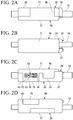
- the sensor assembly 20 includes the housing 25 and a sensor intermediate body 50 that is housed in the housing 25.
- the housing 25 includes a first housing 30 and a second housing 70, and covers and hides the sensor intermediate body 50.
- the second housing 70 includes a resin molded body that is previously formed through injection molding with respect to the first housing 30 housing the coil element 10 and the sensor intermediate body 50.
- thermosensitive body 52 In the sensor assembly 20, when the coil element 10 is fixed to a predetermined position, the thermosensitive body 52 is positioned at a predetermined position of the coil element 10.
- the first housing 30 includes a holding groove 31 holding the coil element 10 and the sensor intermediate body 50.
- the holding groove 31 penetrates through the first housing 30 in a longitudinal direction L.
- the first housing 30 is integrally molded through injection molding of an electrically insulating resin material.
- the resin material for example, polyphenylene sulfide (PPS) resin and polyamide (PA) resin may be used.
- the second housing 70 is made from the same resin material.
- the resin material configuring the first housing 30 and the second housing 70 has rigidity higher than rigidity of a fluorine resin configuring the covering body 60. Accordingly, the sensor assembly 20 is firmly fixed to the coil element 10.
- the holding groove 31 is provided in a space surrounded by a bottom floor 33, a side wall 34, a first end wall 37, an intermediate wall 41, and a second end wall 43.
- the side wall 34 is provided on one edge of the bottom floor 33 in a width direction W.
- the first end wall 37, the intermediate wall 41, and the second end wall 43 are provided on the other edge of the bottom floor 33 in the width direction W.
- the side wall 34, the first end wall 37, the intermediate wall 41, and the second end wall 43 perpendicularly stand on the bottom floor 33, and the side wall 34 is provided with a predetermined gap in the width direction W from the first end wall 37, the intermediate wall 41, and the second end wall 43.
- the side wall 34 is provided over the entire region in the longitudinal direction L at the one edge of the first housing 30 in the width direction W.
- an inner surface 35A facing the holding groove 31 is made flat whereas an outer surface 35B on the rear side of the inner surface 35A includes a broad locking groove 36 into which a part of the second housing 70 is inserted.
- the locking groove 36 is recessed toward the holding groove 31 side from the other outer surface 35B.
- the first end wall 37 is provided on one end of the first housing 30 in the longitudinal direction L.
- the first end wall 37 includes electric wire holding holes 38 and 38 into which lead wires 56 and 56 drawn from the sensor intermediate body 50 are respectively inserted.
- the electric wire holding holes 38 and 38 penetrate through the first end wall 37 in the longitudinal direction L.
- first end wall 37 includes a first coil holding surface 39 facing the side wall 34.
- the first coil holding surface 39 abuts on the coil element 10 housed in the holding groove 31, thereby holding, together with the side wall 34, the coil element 10 in the width direction W.
- the intermediate wall 41 is provided at a substantially center position of the first housing 30 in the longitudinal direction L, with a predetermined gap from the first end wall 37.
- the intermediate wall 41 includes a first sensor holding surface 42 facing the side wall 34.
- the first sensor holding surface 42 abuts on the sensor intermediate body 50 housed in the holding groove 31, thereby holding, together with the side wall 34, the sensor intermediate body 50 and the coil element 10 in the width direction W.
- the second end wall 43 is provided on the other end of the first housing 30 in the longitudinal direction L.
- the second end wall 43 is formed in an L-shape in a planar view, and includes a second sensor holding surface 44 and a second coil holding surface 45 both facing the side wall 34.
- the second sensor holding surface 44 abuts on the sensor intermediate body 50 housed in the holding groove 31, thereby holding, together with the side wall 34, the sensor intermediate body 50 in the width direction W.
- the second coil holding surface 45 abuts on the sensor intermediate body 50 housed in the holding groove 31, thereby holding, together with the side wall 34, the sensor intermediate body 50 in the width direction W.
- a gap 47 is provided between the first end wall 37 and the intermediate wall 41, and is filled with the first locking part 73 that is a part of the second housing 70.
- a gap 48 is also provided between the second end wall 43 and the intermediate wall 41, and is filled with the second locking part 75 that is a part of the second housing 70.
- the view window 76 is provided in the second locking part 75 that fills the gap 48.
- the sensor intermediate body 50 includes an element main body 51, paired extraction wires 55 and 55, and the lead wires 56 and 56.
- the paired extraction wires 55 and 55 are electrically connected to the element main body 51.
- the lead wires 56 and 56 are respectively electrically connected to the extraction wires 55 and 55.
- a side provided with the element main body 51 is defined as a forward side of the temperature sensor 1, and a side from which the lead wires 56 and 56 are drawn is defined as a rearward side.
- the element main body 51 is a cylindrical member that includes the thermosensitive body 52 having temperature characteristics in electric resistance, and a sealing glass 53 covering surroundings of the thermosensitive body 52.
- the thermosensitive body 52 includes, for example, a material having temperature characteristics in electric resistance, like a thermistor.
- the sealing glass 53 is provided to seal and maintain the thermosensitive body 52 in an airtight state, thereby preventing chemical change and physical change based on an environmental condition from occurring on the thermosensitive body 52.
- Amorphous glass and crystalline glass are both usable as the sealing glass 53, or the amorphous glass and the crystalline glass are mixed so as to have a desired linear expansion coefficient and such a mixture may be used as the sealing glass 53.
- the extraction wires 55 and 55 each include, for example, Dumet wire, and are electrically connected to the thermosensitive body 52 through an unillustrated electrode.
- the Dumet wire includes an inner layer and an outer layer provided around the inner layer.
- the inner layer contains an iron-nickel alloy having a linear expansion coefficient close to that of glass, and the outer layer is cladded with copper or a copper alloy having high electroconductivity.
- each of the lead wires 56 and 56 respectively includes a twisted wire in which thin core wires are twisted, and an electrically insulating covering layers 57 and 57 covering the twisted wire.
- the lead wires 56 and 56 are connected to an unillustrated temperature measurement circuit through other electric wires as necessary.
- the covering layers 57 and 57 each contain a fluorine resin such as polytetrafluoroethylene (PTFE) and a tetrafluoroethylene-perfluoroalkylvinylether copolymer (PFA).
- the whole of the element main body 51 and the extraction wires 55 and 55 and a part of the lead wires 56 and 56 are covered with the electrically insulating covering body 60, and the element main body 51 is protected from the surrounding environment.
- the covering body 60 includes a substantially rectangular parallelepiped shape, and includes an inner layer 61 and an outer layer 63.
- the inner layer 61 is disposed inside the outer layer 63, and directly covers the element main body 51.
- the inner layer 61 air-tightly seals a portion from a front end of the element main body 51 to the middle of the lead wires 56 and 56.
- the inner layer 61 is formed of a fluorine resin containing a tetrafluoroethylene-perfluoroalkylvinylether copolymer (PFA).
- PFA tetrafluoroethylene-perfluoroalkylvinylether copolymer
- the PTFE and the PFA are fluorine resins and have excellent resistance in common; however, the PTFE has a melting point higher than that of the PFA.
- the PTFE and the PFA both include transparency, and in particular, the PFA include high transparency.
- the outer layer 63 is provided in close contact with outside of the inner layer 61.
- the outer layer 63 provides, together with the inner layer 61, resistance to the element main body 51, and holds the inner layer 61 that is melted in a manufacturing process. Accordingly, the outer layer 63 contains the PTFE that has a melting point higher than that of the PFA forming the inner layer 61.
- the outer layer 63 includes the flat detection surface 65, and the detection surface 65 comes into contact with the flat detection surface 12 of the coil element 10. As a result, the covering body 60 and the coil element 10 come into surface contact with each other.
- the covering body 60 is fabricated by preparing an inner layer tube corresponding to the inner layer 61 and an outer layer tube corresponding to the outer layer 63, inserting the element main body 51 into the inner layer tube and disposing the outer layer tube on the outside of the inner layer tube, and performing heating and pressurization.
- the melting point of the PFA configuring the inner layer tube is 302°C to 310°C whereas the melting point of the PTFE configuring the outer layer tube is 327°C. Therefore, if both are heated to, for example, 315°C, the inner layer tube is melted but the outer layer tube is not melted and can maintain its shape. The outer layer tube, however, contracts when heated to this temperature.
- the PTFE includes a linear expansion coefficient of about 10 ⁇ 10 -5/ °C, and strongly compresses the inner layer tube in the melted state. This contributes to densification of the inner layer 61, and airtightness between the inner layer 61 and the outer layer 63 is secured by pressure generated therebetween.
- Press working is performed with use of a mold having a rectangular parallelepiped cavity while the inner layer tube is melted, which results in the rectangular parallelepiped covering body 60.
- a transparent fluorine resin is used as the covering body 60. This allows for visual confirmation of soundness of the element main body 51 buried inside the covering body 60 through the view window 76.
- the fluorine resin is rich in elasticity as compared with other resin materials. Accordingly, even if the coil element 10 as a temperature detection object vibrates, the covering body 60 follows the vibration and is tightly pressed against the coil element 10.
- the second housing 70 covers and hides the coil element 10 and the sensor intermediate body 50 that are housed in the first housing 30, from a thickness direction T, and holds, together with the first housing 30, the coil element 10 and the sensor intermediate body 50.
- the second housing 70 includes a base part 71 that covers and hides the holding groove 31.
- the second housing 70 includes the first locking part 73, the second locking part 75, and the third locking part 77.
- the first locking part 73 communicates with the base part 71 and fills the gap 47 between the first end wall 37 and the intermediate wall 41.
- the second locking part 75 communicates with the base part 71 and fills the gap 48 between the second end wall 43 and the intermediate wall 41.
- the third locking part 77 fills the locking groove 36 of the side wall 34.
- the base part 71, the first locking part 73, the second locking part 75, and the third locking part 77 that are integrally formed are provided over four surfaces of the first housing 30. Therefore, the second housing 70 is firmly fixed to the first housing 30 so as not to be displaced in position from each other.
- the second housing 70 includes the view window 76 in the second locking part 75.
- the view window 76 penetrates front and rear surfaces of the second locking part 75, and is provided corresponding to a position at which the thermosensitive body 52 housed in the holding groove 31 is disposed.
- the element main body 51 is covered with the covering body 60.
- the covering body 60 has transparency, and accordingly, the thermosensitive body 52 and the sealing glass 53 are visually confirmable through the view window 76.
- the sensor intermediate body 50 is housed in the holding groove 31 of the first housing 30 disposed such that the holding groove opens upward.
- the sensor intermediate body 50 is housed in the holding groove 31 such that the lead wires 56 and 56 are respectively inserted into the electric wire holding holes 38 and 38 of the first end wall 37.
- a side provided with the first end wall 37, the intermediate wall 41, and the second end wall 43 is referred to as a front side, and a side provided with the side wall 34 is referred to as an inner side.
- the sensor intermediate body 50 is housed at a predetermined position of the first housing 30 when the sensor intermediate body 50 is housed on the front side of the holding groove 31, the lead wires 56 and 56 are respectively inserted into the electric wire holding holes 38 and 38, and the covering body 60 comes into contact with the first sensor holding surface 42 of the intermediate wall 41 and the second sensor holding surface 44 of the second end wall 43.
- the holding groove 31 on the inner side includes, between the sensor intermediate body 50 and the side wall 34, a space to house the coil element 10.
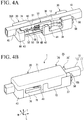
- the coil element 10 is housed in the space of the holding groove 31 as illustrated in FIG. 4A .
- Dimensions of each of the holding groove 31 of the first housing 30, the covering body 60 of the sensor intermediate body 50, and the coil element 10 are set to house the coil element 10 in the space without a gap. Assuming that the temperature sensor 1 is used in an environment in which vibration is applied to the temperature sensor 1, a slight interference is preferably provided between the space and the coil element 10, and fitting the coil element 10 into the space preferably causes the coil element 10 and the sensor intermediate body 50 to press against each other.
- the coil element 10 has the dimension in the longitudinal direction L larger than the dimension of the first housing 30, and is housed in the holding groove 31 such that both ends of the coil element 10 project from the first housing 30.
- the coil element 10 comes into contact with the side wall 34 on the inner side.
- the surface as the temperature detection object of the coil element 10 comes into contact with the covering body 60 of the sensor intermediate body 50 as well as the first coil holding surface 39 of the first end wall 37 and the second coil holding surface 45 of the second end wall 43.
- the coil element 10 is housed at the predetermined position of the first housing 30.
- the second housing 70 is formed through injection molding as illustrated in FIG. 4B .
- the thermosensitive body 52 and the sealing glass 53 receives considerable pressure, which may cause breakage of the thermosensitive body 52.
- the second housing 70 is formed such that the holding groove 31 of the first housing 30 is sealed from the outside, and the coil element 10 and the sensor intermediate body 50 housed in the holding groove 31 are covered with and hidden by the second housing 70. This prevents the thermosensitive body 52 from being thermally influenced by any part other than the coil element 10, and strengthens the fixing of the coil element 10 and the sensor intermediate body 50.
- the second housing 70 is formed to include the view window 76 in the second locking part 75.
- the view window 76 penetrates the front and rear surfaces of the second locking part 75, which allows for visual confirmation of the covering body 60 of the sensor intermediate body 50 from the outside.
- the view window 76 is provided at a position corresponding to the thermosensitive body 52 of the sensor intermediate body 50.
- the view window 76 is provided at the position corresponding to the sensor intermediate body 50 of the thermosensitive body 52. This allows for visual confirmation of soundness of the thermosensitive body 52 and the sealing glass 53 from the outside even after the second housing 70 is formed. Therefore, according to the temperature sensor 1, it is possible to detect a defective thermosensitive body 52 after the second housing 70 is formed and to eliminate the temperature sensor 1.
- the element main body 51 including the thermosensitive body 52 is covered with the transparent covering body 60 in the temperature sensor 1, which allows for visual confirmation of the soundness of the thermosensitive body 52 while protecting the element main body 51.
- the covering body 60 including the fluorine resin is rich in elasticity among resin materials. Therefore, even if the coil element 10 as the temperature detection object vibrates, the covering body 60 follows the vibration and is tightly pressed against the coil element 10. This contributes to accuracy improvement of the detection temperature.
- the covering body 60 is rich in elasticity, it is advantageous to provide the view window 76 in the second housing 70.
- a part of the mold is disposed at the positions respectively corresponding to the view window 76, and the part of the mold comes into contact with the covering body 60 housed in the holding groove 31.
- the melted resin configuring the second housing 70 enters between the mold and the covering body 60 and covers the view window 76, which inhibits visual confirmation of the thermosensitive body 52.
- the covering body 60 according to the present embodiment is not broken because the covering body 60 is rich in elasticity.
- the covering body 60 contains a resin material similar to that of the second housing 70, the covering body 60 may be broken when the contact force of the mold and the covering body 60 is increased. Therefore, it is necessary to strictly adjust the contact force of the mold and the covering body 60.
- such adjustment is unnecessary because the covering body 60 is rich in elasticity. This facilitates manufacturing of the temperature sensor 1.
- the lead wires 56 and 56 of the element main body 51 are respectively inserted into the electric wire holding holes 38 and 38 of the first housing 30 and are held by the first end wall 37.
- the lead wires 56 and 56 are held by the first end wall 37 at a time when the element main body 51 is housed in the first housing 30. Accordingly, the positions of the lead wires 56 and 56 are maintained even when the injection molding to form the second housing 70 is performed thereafter. Therefore, the melted resin does not damage the lead wires 56 and 56 even if touching, and the lead wires 56 and 56 may be drawn from the first housing 30.
- the temperature sensor 1 includes only one view window 76 in the second locking part 75; however, the present invention is not limited thereto.
- a view window similar to the view window 76 may be provided in the third locking part 77 that is a rear surface with respect to the view window 76.
- the view window 76 is provided in the second housing 70 including the resin molded body; however, the present invention is not limited thereto.
- the view window may be provided on the first housing 30 that is previously prepared as an injection molded product, or may be provided in both of the first housing 30 and the second housing 70.
- the view window 76 is formed at a time when the first housing 30 is formed through injection molding.
- the covering body 60 is optional in the present invention, and the covering body 60 may include other transparent resin material, or may not be provided.
Landscapes
- Engineering & Computer Science (AREA)
- Physics & Mathematics (AREA)
- General Physics & Mathematics (AREA)
- Microelectronics & Electronic Packaging (AREA)
- Power Engineering (AREA)
- Measuring Temperature Or Quantity Of Heat (AREA)
Applications Claiming Priority (1)
| Application Number | Priority Date | Filing Date | Title |
|---|---|---|---|
| PCT/JP2017/010609 WO2018167903A1 (ja) | 2017-03-16 | 2017-03-16 | 温度センサ |
Publications (3)
| Publication Number | Publication Date |
|---|---|
| EP3401658A1 EP3401658A1 (en) | 2018-11-14 |
| EP3401658A4 EP3401658A4 (en) | 2019-01-02 |
| EP3401658B1 true EP3401658B1 (en) | 2021-05-05 |
Family
ID=61629115
Family Applications (1)
| Application Number | Title | Priority Date | Filing Date |
|---|---|---|---|
| EP17859378.6A Active EP3401658B1 (en) | 2017-03-16 | 2017-03-16 | Temperature sensor |
Country Status (5)
| Country | Link |
|---|---|
| US (1) | US10935434B2 (ja) |
| EP (1) | EP3401658B1 (ja) |
| JP (1) | JP6297765B1 (ja) |
| CN (1) | CN108885142B (ja) |
| WO (1) | WO2018167903A1 (ja) |
Families Citing this family (17)
| Publication number | Priority date | Publication date | Assignee | Title |
|---|---|---|---|---|
| JP6419756B2 (ja) * | 2016-06-23 | 2018-11-07 | 株式会社芝浦電子 | 温度検出装置 |
| US10935434B2 (en) * | 2017-03-16 | 2021-03-02 | Shibaura Electronics Co., Ltd. | Temperature sensor |
| US11237062B2 (en) * | 2018-03-30 | 2022-02-01 | Shibaura Electronics Co., Ltd. | Temperature detection device and assembly thereof |
| EP3715806B1 (en) * | 2018-08-02 | 2022-04-20 | Shibaura Electronics Co., Ltd. | Temperature sensing device and assembly |
| JP7172732B2 (ja) * | 2019-02-27 | 2022-11-16 | 株式会社デンソー | 回転電機、その温度検出器、その製造方法、および保護方法 |
| DE102019121189A1 (de) * | 2019-04-26 | 2020-10-29 | Schaeffler Technologies AG & Co. KG | Elektrische Maschine |
| CN110307808A (zh) * | 2019-07-11 | 2019-10-08 | 中国航发哈尔滨东安发动机有限公司 | 一种温度传感器位置精度检验方法 |
| CN110296762A (zh) * | 2019-07-29 | 2019-10-01 | 鹤壁天海环球电器有限公司 | 一种温度传感器的密封保护装置 |
| JP6830278B1 (ja) * | 2019-12-24 | 2021-02-17 | 株式会社大泉製作所 | 温度センサ |
| DE102020107863A1 (de) * | 2020-03-23 | 2021-09-23 | Schaeffler Technologies AG & Co. KG | Vorrichtung zur Temperaturerfassung bei elektrischen Maschinen und elektrische Maschine mit Temperaturerfassung |
| DE102020118224A1 (de) | 2020-06-30 | 2021-12-30 | Schaeffler Technologies AG & Co. KG | Stator |
| EP4030156B1 (en) * | 2020-11-06 | 2023-01-04 | Shibaura Electronics Co., Ltd. | Temperature sensor |
| DE102020215884A1 (de) | 2020-12-15 | 2022-06-15 | Volkswagen Aktiengesellschaft | Sensoranordnung für einen Elektromotor, Elektromotor mit einer solchen sowie Verfahren zur Einbindung eines Messelementes in einen Elektromotor |
| CN113675999B (zh) * | 2021-07-09 | 2022-07-01 | 东风电驱动系统有限公司 | 一种新能源电机定子用温度传感器及其装配方法 |
| WO2023062787A1 (ja) * | 2021-10-14 | 2023-04-20 | 株式会社芝浦電子 | 温度センサおよび温度センサの製造方法 |
| CN116249881A (zh) * | 2022-03-03 | 2023-06-09 | 株式会社芝浦电子 | 温度传感器、组装体、旋转电机及温度传感器的制造方法 |
| JP1729419S (ja) * | 2022-03-18 | 2022-11-09 | 温度センサ |
Citations (1)
| Publication number | Priority date | Publication date | Assignee | Title |
|---|---|---|---|---|
| JPH10229663A (ja) * | 1997-02-17 | 1998-08-25 | Kitagawa Ind Co Ltd | サーマルプロテクタ用保護ケース及び該保護ケース付きサーマルプロテクタ |
Family Cites Families (35)
| Publication number | Priority date | Publication date | Assignee | Title |
|---|---|---|---|---|
| US3321635A (en) * | 1964-02-05 | 1967-05-23 | Gen Motors Corp | Coulometric control |
| JPS527535B2 (ja) * | 1972-05-02 | 1977-03-03 | ||
| JPS5786017A (en) * | 1980-11-18 | 1982-05-28 | Matsushita Electric Ind Co Ltd | Temperature sensor element |
| DE3528161C1 (de) * | 1985-08-06 | 1986-10-23 | Degussa Ag, 6000 Frankfurt | Thermoelement zur Messung von Temperaturen in Vakuumoefen |
| US5177832A (en) * | 1991-04-15 | 1993-01-12 | Mccoy Daniel W | Apparatus for suction cleaning traveling textile yarns |
| JPH05208423A (ja) * | 1992-01-30 | 1993-08-20 | Nissei Denki Kk | サーミスタのモールド加工方法 |
| IT1273015B (it) * | 1994-07-27 | 1997-07-01 | Piefrancesco Pavoni | "dispositivo per il rilevamento termometrico invasivo e per l'introduzione di un medicamento per applicazioni di ipertermia superficiale e profonda". |
| JP3344684B2 (ja) * | 1996-05-20 | 2002-11-11 | 株式会社村田製作所 | 電子部品 |
| JP2921752B2 (ja) * | 1996-09-18 | 1999-07-19 | ファナック株式会社 | 電動機の巻線温度検出素子の取付け方法および取付け具 |
| DE19648332C2 (de) * | 1996-11-22 | 2000-11-23 | Messko Albert Hauser Gmbh & Co | Verfahren zur Nachbildung und Anzeige der Wicklungstemperatur eines elektrischen Leistungstransformators und Thermometer zur Durchführung des Verfahrens |
| TW463184B (en) * | 1999-04-09 | 2001-11-11 | Murata Manufacturing Co | Temperature sensor, method of producing same and method of mounting same to a circuit board |
| US7111983B2 (en) * | 2004-04-13 | 2006-09-26 | Reliance Electric Technologies, Llc | Temperature detection method and apparatus for inverter-driven machines |
| US20070171958A1 (en) * | 2006-01-23 | 2007-07-26 | Anh Hoang | Electrical device measurement probes |
| US8454228B2 (en) * | 2009-03-06 | 2013-06-04 | Matthew Skinner | Thermal detector testing device |
| CN102812624A (zh) * | 2010-03-24 | 2012-12-05 | 丰田自动车株式会社 | 使温度检测元件邻接的器具 |
| JP5609275B2 (ja) | 2010-06-02 | 2014-10-22 | 日産自動車株式会社 | 温度センサの取り付け構造および温度センサの取り付け方法 |
| US8316789B2 (en) * | 2010-08-11 | 2012-11-27 | Wolosuk Susan M | Shielded meat temperature sensing device |
| JP5672984B2 (ja) * | 2010-11-04 | 2015-02-18 | アイシン精機株式会社 | 回転電機のステータ |
| JP2014138544A (ja) * | 2013-01-18 | 2014-07-28 | Fanuc Ltd | コイルエンドを保持する保持部材を有する電動機の温度測定装置 |
| JP5827288B2 (ja) * | 2013-09-13 | 2015-12-02 | トヨタ自動車株式会社 | サーミスタモジュール |
| JP5726277B1 (ja) * | 2013-11-29 | 2015-05-27 | 三菱電機株式会社 | 回転電機、回転電機の固定子、及び回転電機の固定子の製造方法 |
| KR102159166B1 (ko) * | 2014-05-09 | 2020-09-23 | 삼성전자주식회사 | 색분리 소자 및 상기 색분리 소자를 포함하는 이미지 센서 |
| JP6243310B2 (ja) * | 2014-09-25 | 2017-12-06 | トヨタ自動車株式会社 | ステータコイルの温度センサ固定構造 |
| WO2016120929A1 (ja) * | 2015-01-29 | 2016-08-04 | 株式会社芝浦電子 | 温度センサ |
| JP5834167B1 (ja) * | 2015-02-26 | 2015-12-16 | 株式会社芝浦電子 | 温度センサ |
| EP3306291B1 (en) * | 2015-05-25 | 2020-07-08 | Nissan Motor Co., Ltd. | Temperature sensor mounting structure |
| FR3037738B1 (fr) | 2015-06-22 | 2019-07-05 | Valeo Equipements Electriques Moteur | Stator a connecteur equipe d'une unite de mesure thermique et machine electrique comportant un tel stator |
| JP6440589B2 (ja) * | 2015-07-24 | 2018-12-19 | 株式会社芝浦電子 | 温度検出装置 |
| US10371739B2 (en) * | 2015-10-30 | 2019-08-06 | Landis+Gyr Llc | Arrangement for detecting a meter maintenance condition using winding resistance |
| JP6419756B2 (ja) * | 2016-06-23 | 2018-11-07 | 株式会社芝浦電子 | 温度検出装置 |
| CN206114130U (zh) * | 2016-11-01 | 2017-04-19 | 湖北文理学院 | 一种电机绕组测温传感器 |
| JP6913170B2 (ja) * | 2016-12-22 | 2021-08-04 | アボット・ラボラトリーズAbbott Laboratories | 生体キャリーオーバーを低減するための誘導加熱システムおよび誘導加熱システムを制御する方法 |
| US10935434B2 (en) * | 2017-03-16 | 2021-03-02 | Shibaura Electronics Co., Ltd. | Temperature sensor |
| EP3556872B1 (en) * | 2017-04-11 | 2021-03-03 | Shibaura Electronics Co., Ltd. | Temperature sensor |
| JP7044686B2 (ja) * | 2018-11-02 | 2022-03-30 | 三菱重工業株式会社 | 回転電機の温度監視システムおよび温度監視方法 |
-
2017
- 2017-03-16 US US15/769,660 patent/US10935434B2/en active Active
- 2017-03-16 JP JP2017562367A patent/JP6297765B1/ja active Active
- 2017-03-16 WO PCT/JP2017/010609 patent/WO2018167903A1/ja unknown
- 2017-03-16 EP EP17859378.6A patent/EP3401658B1/en active Active
- 2017-03-16 CN CN201780003478.1A patent/CN108885142B/zh active Active
Patent Citations (1)
| Publication number | Priority date | Publication date | Assignee | Title |
|---|---|---|---|---|
| JPH10229663A (ja) * | 1997-02-17 | 1998-08-25 | Kitagawa Ind Co Ltd | サーマルプロテクタ用保護ケース及び該保護ケース付きサーマルプロテクタ |
Also Published As
| Publication number | Publication date |
|---|---|
| EP3401658A1 (en) | 2018-11-14 |
| WO2018167903A1 (ja) | 2018-09-20 |
| EP3401658A4 (en) | 2019-01-02 |
| CN108885142A (zh) | 2018-11-23 |
| US10935434B2 (en) | 2021-03-02 |
| CN108885142B (zh) | 2019-11-26 |
| JP6297765B1 (ja) | 2018-03-20 |
| JPWO2018167903A1 (ja) | 2019-03-28 |
| US20190265108A1 (en) | 2019-08-29 |
Similar Documents
| Publication | Publication Date | Title |
|---|---|---|
| EP3401658B1 (en) | Temperature sensor | |
| EP3825668B1 (en) | Temperature sensor | |
| CN109073477B (zh) | 温度检测装置 | |
| EP3264056B1 (en) | Temperature sensor | |
| JP6440589B2 (ja) | 温度検出装置 | |
| US11258209B2 (en) | Sealed electrical plug with temperature sensors | |
| US20110044374A1 (en) | Temperature sensor | |
| JP2019012083A (ja) | 温度検出装置 | |
| US20220320971A1 (en) | Temperature sensor and electric motor | |
| US20190064000A1 (en) | Temperature sensor | |
| JP6785925B2 (ja) | 温度センサおよび温度センサの製造方法 | |
| JP7489747B2 (ja) | 温度センサ付き配線部品 | |
| JP2022109643A (ja) | 温度センサ付き配線部品 | |
| JP2020134475A (ja) | 温度センサ | |
| KR20160129298A (ko) | 하우징이 구비된 온도센서 |
Legal Events
| Date | Code | Title | Description |
|---|---|---|---|
| STAA | Information on the status of an ep patent application or granted ep patent |
Free format text: STATUS: UNKNOWN |
|
| STAA | Information on the status of an ep patent application or granted ep patent |
Free format text: STATUS: THE INTERNATIONAL PUBLICATION HAS BEEN MADE |
|
| PUAI | Public reference made under article 153(3) epc to a published international application that has entered the european phase |
Free format text: ORIGINAL CODE: 0009012 |
|
| STAA | Information on the status of an ep patent application or granted ep patent |
Free format text: STATUS: REQUEST FOR EXAMINATION WAS MADE |
|
| 17P | Request for examination filed |
Effective date: 20180420 |
|
| AK | Designated contracting states |
Kind code of ref document: A1 Designated state(s): AL AT BE BG CH CY CZ DE DK EE ES FI FR GB GR HR HU IE IS IT LI LT LU LV MC MK MT NL NO PL PT RO RS SE SI SK SM TR |
|
| AX | Request for extension of the european patent |
Extension state: BA ME |
|
| REG | Reference to a national code |
Ref country code: DE Ref legal event code: R079 Ref document number: 602017038345 Country of ref document: DE Free format text: PREVIOUS MAIN CLASS: G01K0007000000 Ipc: G01K0001140000 |
|
| A4 | Supplementary search report drawn up and despatched |
Effective date: 20181129 |
|
| RIC1 | Information provided on ipc code assigned before grant |
Ipc: H02K 11/25 20160101ALI20181123BHEP Ipc: G01K 1/14 20060101AFI20181123BHEP |
|
| STAA | Information on the status of an ep patent application or granted ep patent |
Free format text: STATUS: EXAMINATION IS IN PROGRESS |
|
| 17Q | First examination report despatched |
Effective date: 20191118 |
|
| GRAP | Despatch of communication of intention to grant a patent |
Free format text: ORIGINAL CODE: EPIDOSNIGR1 |
|
| STAA | Information on the status of an ep patent application or granted ep patent |
Free format text: STATUS: GRANT OF PATENT IS INTENDED |
|
| DAV | Request for validation of the european patent (deleted) | ||
| DAX | Request for extension of the european patent (deleted) | ||
| INTG | Intention to grant announced |
Effective date: 20200415 |
|
| RIN1 | Information on inventor provided before grant (corrected) |
Inventor name: YOSHIHARA, TAKAMASA Inventor name: KIRIHARA, MASANORI Inventor name: TAKEMURA, MICHIRU |
|
| GRAJ | Information related to disapproval of communication of intention to grant by the applicant or resumption of examination proceedings by the epo deleted |
Free format text: ORIGINAL CODE: EPIDOSDIGR1 |
|
| STAA | Information on the status of an ep patent application or granted ep patent |
Free format text: STATUS: EXAMINATION IS IN PROGRESS |
|
| INTC | Intention to grant announced (deleted) | ||
| GRAS | Grant fee paid |
Free format text: ORIGINAL CODE: EPIDOSNIGR3 |
|
| STAA | Information on the status of an ep patent application or granted ep patent |
Free format text: STATUS: GRANT OF PATENT IS INTENDED |
|
| GRAP | Despatch of communication of intention to grant a patent |
Free format text: ORIGINAL CODE: EPIDOSNIGR1 |
|
| STAA | Information on the status of an ep patent application or granted ep patent |
Free format text: STATUS: GRANT OF PATENT IS INTENDED |
|
| INTG | Intention to grant announced |
Effective date: 20201105 |
|
| GRAA | (expected) grant |
Free format text: ORIGINAL CODE: 0009210 |
|
| STAA | Information on the status of an ep patent application or granted ep patent |
Free format text: STATUS: THE PATENT HAS BEEN GRANTED |
|
| AK | Designated contracting states |
Kind code of ref document: B1 Designated state(s): AL AT BE BG CH CY CZ DE DK EE ES FI FR GB GR HR HU IE IS IT LI LT LU LV MC MK MT NL NO PL PT RO RS SE SI SK SM TR |
|
| REG | Reference to a national code |
Ref country code: GB Ref legal event code: FG4D |
|
| REG | Reference to a national code |
Ref country code: CH Ref legal event code: EP |
|
| REG | Reference to a national code |
Ref country code: AT Ref legal event code: REF Ref document number: 1390390 Country of ref document: AT Kind code of ref document: T Effective date: 20210515 |
|
| REG | Reference to a national code |
Ref country code: IE Ref legal event code: FG4D |
|
| REG | Reference to a national code |
Ref country code: DE Ref legal event code: R096 Ref document number: 602017038345 Country of ref document: DE |
|
| REG | Reference to a national code |
Ref country code: LT Ref legal event code: MG9D |
|
| REG | Reference to a national code |
Ref country code: AT Ref legal event code: MK05 Ref document number: 1390390 Country of ref document: AT Kind code of ref document: T Effective date: 20210505 |
|
| PG25 | Lapsed in a contracting state [announced via postgrant information from national office to epo] |
Ref country code: HR Free format text: LAPSE BECAUSE OF FAILURE TO SUBMIT A TRANSLATION OF THE DESCRIPTION OR TO PAY THE FEE WITHIN THE PRESCRIBED TIME-LIMIT Effective date: 20210505 Ref country code: BG Free format text: LAPSE BECAUSE OF FAILURE TO SUBMIT A TRANSLATION OF THE DESCRIPTION OR TO PAY THE FEE WITHIN THE PRESCRIBED TIME-LIMIT Effective date: 20210805 Ref country code: AT Free format text: LAPSE BECAUSE OF FAILURE TO SUBMIT A TRANSLATION OF THE DESCRIPTION OR TO PAY THE FEE WITHIN THE PRESCRIBED TIME-LIMIT Effective date: 20210505 Ref country code: FI Free format text: LAPSE BECAUSE OF FAILURE TO SUBMIT A TRANSLATION OF THE DESCRIPTION OR TO PAY THE FEE WITHIN THE PRESCRIBED TIME-LIMIT Effective date: 20210505 Ref country code: LT Free format text: LAPSE BECAUSE OF FAILURE TO SUBMIT A TRANSLATION OF THE DESCRIPTION OR TO PAY THE FEE WITHIN THE PRESCRIBED TIME-LIMIT Effective date: 20210505 |
|
| PG25 | Lapsed in a contracting state [announced via postgrant information from national office to epo] |
Ref country code: SE Free format text: LAPSE BECAUSE OF FAILURE TO SUBMIT A TRANSLATION OF THE DESCRIPTION OR TO PAY THE FEE WITHIN THE PRESCRIBED TIME-LIMIT Effective date: 20210505 Ref country code: RS Free format text: LAPSE BECAUSE OF FAILURE TO SUBMIT A TRANSLATION OF THE DESCRIPTION OR TO PAY THE FEE WITHIN THE PRESCRIBED TIME-LIMIT Effective date: 20210505 Ref country code: PL Free format text: LAPSE BECAUSE OF FAILURE TO SUBMIT A TRANSLATION OF THE DESCRIPTION OR TO PAY THE FEE WITHIN THE PRESCRIBED TIME-LIMIT Effective date: 20210505 Ref country code: NO Free format text: LAPSE BECAUSE OF FAILURE TO SUBMIT A TRANSLATION OF THE DESCRIPTION OR TO PAY THE FEE WITHIN THE PRESCRIBED TIME-LIMIT Effective date: 20210805 Ref country code: PT Free format text: LAPSE BECAUSE OF FAILURE TO SUBMIT A TRANSLATION OF THE DESCRIPTION OR TO PAY THE FEE WITHIN THE PRESCRIBED TIME-LIMIT Effective date: 20210906 Ref country code: LV Free format text: LAPSE BECAUSE OF FAILURE TO SUBMIT A TRANSLATION OF THE DESCRIPTION OR TO PAY THE FEE WITHIN THE PRESCRIBED TIME-LIMIT Effective date: 20210505 Ref country code: GR Free format text: LAPSE BECAUSE OF FAILURE TO SUBMIT A TRANSLATION OF THE DESCRIPTION OR TO PAY THE FEE WITHIN THE PRESCRIBED TIME-LIMIT Effective date: 20210806 Ref country code: IS Free format text: LAPSE BECAUSE OF FAILURE TO SUBMIT A TRANSLATION OF THE DESCRIPTION OR TO PAY THE FEE WITHIN THE PRESCRIBED TIME-LIMIT Effective date: 20210905 |
|
| REG | Reference to a national code |
Ref country code: NL Ref legal event code: MP Effective date: 20210505 |
|
| PG25 | Lapsed in a contracting state [announced via postgrant information from national office to epo] |
Ref country code: NL Free format text: LAPSE BECAUSE OF FAILURE TO SUBMIT A TRANSLATION OF THE DESCRIPTION OR TO PAY THE FEE WITHIN THE PRESCRIBED TIME-LIMIT Effective date: 20210505 |
|
| PG25 | Lapsed in a contracting state [announced via postgrant information from national office to epo] |
Ref country code: SK Free format text: LAPSE BECAUSE OF FAILURE TO SUBMIT A TRANSLATION OF THE DESCRIPTION OR TO PAY THE FEE WITHIN THE PRESCRIBED TIME-LIMIT Effective date: 20210505 Ref country code: SM Free format text: LAPSE BECAUSE OF FAILURE TO SUBMIT A TRANSLATION OF THE DESCRIPTION OR TO PAY THE FEE WITHIN THE PRESCRIBED TIME-LIMIT Effective date: 20210505 Ref country code: EE Free format text: LAPSE BECAUSE OF FAILURE TO SUBMIT A TRANSLATION OF THE DESCRIPTION OR TO PAY THE FEE WITHIN THE PRESCRIBED TIME-LIMIT Effective date: 20210505 Ref country code: ES Free format text: LAPSE BECAUSE OF FAILURE TO SUBMIT A TRANSLATION OF THE DESCRIPTION OR TO PAY THE FEE WITHIN THE PRESCRIBED TIME-LIMIT Effective date: 20210505 Ref country code: DK Free format text: LAPSE BECAUSE OF FAILURE TO SUBMIT A TRANSLATION OF THE DESCRIPTION OR TO PAY THE FEE WITHIN THE PRESCRIBED TIME-LIMIT Effective date: 20210505 Ref country code: CZ Free format text: LAPSE BECAUSE OF FAILURE TO SUBMIT A TRANSLATION OF THE DESCRIPTION OR TO PAY THE FEE WITHIN THE PRESCRIBED TIME-LIMIT Effective date: 20210505 Ref country code: RO Free format text: LAPSE BECAUSE OF FAILURE TO SUBMIT A TRANSLATION OF THE DESCRIPTION OR TO PAY THE FEE WITHIN THE PRESCRIBED TIME-LIMIT Effective date: 20210505 |
|
| REG | Reference to a national code |
Ref country code: DE Ref legal event code: R097 Ref document number: 602017038345 Country of ref document: DE |
|
| PLBE | No opposition filed within time limit |
Free format text: ORIGINAL CODE: 0009261 |
|
| STAA | Information on the status of an ep patent application or granted ep patent |
Free format text: STATUS: NO OPPOSITION FILED WITHIN TIME LIMIT |
|
| 26N | No opposition filed |
Effective date: 20220208 |
|
| PG25 | Lapsed in a contracting state [announced via postgrant information from national office to epo] |
Ref country code: IS Free format text: LAPSE BECAUSE OF FAILURE TO SUBMIT A TRANSLATION OF THE DESCRIPTION OR TO PAY THE FEE WITHIN THE PRESCRIBED TIME-LIMIT Effective date: 20210905 Ref country code: AL Free format text: LAPSE BECAUSE OF FAILURE TO SUBMIT A TRANSLATION OF THE DESCRIPTION OR TO PAY THE FEE WITHIN THE PRESCRIBED TIME-LIMIT Effective date: 20210505 |
|
| PG25 | Lapsed in a contracting state [announced via postgrant information from national office to epo] |
Ref country code: IT Free format text: LAPSE BECAUSE OF FAILURE TO SUBMIT A TRANSLATION OF THE DESCRIPTION OR TO PAY THE FEE WITHIN THE PRESCRIBED TIME-LIMIT Effective date: 20210505 |
|
| PG25 | Lapsed in a contracting state [announced via postgrant information from national office to epo] |
Ref country code: MC Free format text: LAPSE BECAUSE OF FAILURE TO SUBMIT A TRANSLATION OF THE DESCRIPTION OR TO PAY THE FEE WITHIN THE PRESCRIBED TIME-LIMIT Effective date: 20210505 |
|
| REG | Reference to a national code |
Ref country code: CH Ref legal event code: PL |
|
| GBPC | Gb: european patent ceased through non-payment of renewal fee |
Effective date: 20220316 |
|
| REG | Reference to a national code |
Ref country code: BE Ref legal event code: MM Effective date: 20220331 |
|
| PG25 | Lapsed in a contracting state [announced via postgrant information from national office to epo] |
Ref country code: LU Free format text: LAPSE BECAUSE OF NON-PAYMENT OF DUE FEES Effective date: 20220316 Ref country code: LI Free format text: LAPSE BECAUSE OF NON-PAYMENT OF DUE FEES Effective date: 20220331 Ref country code: IE Free format text: LAPSE BECAUSE OF NON-PAYMENT OF DUE FEES Effective date: 20220316 Ref country code: GB Free format text: LAPSE BECAUSE OF NON-PAYMENT OF DUE FEES Effective date: 20220316 Ref country code: FR Free format text: LAPSE BECAUSE OF NON-PAYMENT OF DUE FEES Effective date: 20220331 Ref country code: CH Free format text: LAPSE BECAUSE OF NON-PAYMENT OF DUE FEES Effective date: 20220331 |
|
| PG25 | Lapsed in a contracting state [announced via postgrant information from national office to epo] |
Ref country code: BE Free format text: LAPSE BECAUSE OF NON-PAYMENT OF DUE FEES Effective date: 20220331 |
|
| PG25 | Lapsed in a contracting state [announced via postgrant information from national office to epo] |
Ref country code: HU Free format text: LAPSE BECAUSE OF FAILURE TO SUBMIT A TRANSLATION OF THE DESCRIPTION OR TO PAY THE FEE WITHIN THE PRESCRIBED TIME-LIMIT; INVALID AB INITIO Effective date: 20170316 |
|
| PG25 | Lapsed in a contracting state [announced via postgrant information from national office to epo] |
Ref country code: MK Free format text: LAPSE BECAUSE OF FAILURE TO SUBMIT A TRANSLATION OF THE DESCRIPTION OR TO PAY THE FEE WITHIN THE PRESCRIBED TIME-LIMIT Effective date: 20210505 Ref country code: CY Free format text: LAPSE BECAUSE OF FAILURE TO SUBMIT A TRANSLATION OF THE DESCRIPTION OR TO PAY THE FEE WITHIN THE PRESCRIBED TIME-LIMIT Effective date: 20210505 |
|
| PGFP | Annual fee paid to national office [announced via postgrant information from national office to epo] |
Ref country code: DE Payment date: 20240320 Year of fee payment: 8 |