EP3556872B1 - Temperature sensor - Google Patents
Temperature sensor Download PDFInfo
- Publication number
- EP3556872B1 EP3556872B1 EP17859379.4A EP17859379A EP3556872B1 EP 3556872 B1 EP3556872 B1 EP 3556872B1 EP 17859379 A EP17859379 A EP 17859379A EP 3556872 B1 EP3556872 B1 EP 3556872B1
- Authority
- EP
- European Patent Office
- Prior art keywords
- coil element
- housing
- sensor
- thermosensitive
- coil
- Prior art date
- Legal status (The legal status is an assumption and is not a legal conclusion. Google has not performed a legal analysis and makes no representation as to the accuracy of the status listed.)
- Active
Links
Images


Classifications
-
- G—PHYSICS
- G01—MEASURING; TESTING
- G01K—MEASURING TEMPERATURE; MEASURING QUANTITY OF HEAT; THERMALLY-SENSITIVE ELEMENTS NOT OTHERWISE PROVIDED FOR
- G01K1/00—Details of thermometers not specially adapted for particular types of thermometer
- G01K1/14—Supports; Fastening devices; Arrangements for mounting thermometers in particular locations
-
- H—ELECTRICITY
- H02—GENERATION; CONVERSION OR DISTRIBUTION OF ELECTRIC POWER
- H02K—DYNAMO-ELECTRIC MACHINES
- H02K11/00—Structural association of dynamo-electric machines with electric components or with devices for shielding, monitoring or protection
- H02K11/20—Structural association of dynamo-electric machines with electric components or with devices for shielding, monitoring or protection for measuring, monitoring, testing, protecting or switching
- H02K11/25—Devices for sensing temperature, or actuated thereby
-
- G—PHYSICS
- G01—MEASURING; TESTING
- G01K—MEASURING TEMPERATURE; MEASURING QUANTITY OF HEAT; THERMALLY-SENSITIVE ELEMENTS NOT OTHERWISE PROVIDED FOR
- G01K7/00—Measuring temperature based on the use of electric or magnetic elements directly sensitive to heat ; Power supply therefor, e.g. using thermoelectric elements
- G01K7/16—Measuring temperature based on the use of electric or magnetic elements directly sensitive to heat ; Power supply therefor, e.g. using thermoelectric elements using resistive elements
- G01K7/22—Measuring temperature based on the use of electric or magnetic elements directly sensitive to heat ; Power supply therefor, e.g. using thermoelectric elements using resistive elements the element being a non-linear resistance, e.g. thermistor
-
- H—ELECTRICITY
- H02—GENERATION; CONVERSION OR DISTRIBUTION OF ELECTRIC POWER
- H02K—DYNAMO-ELECTRIC MACHINES
- H02K5/00—Casings; Enclosures; Supports
- H02K5/04—Casings or enclosures characterised by the shape, form or construction thereof
- H02K5/08—Insulating casings
-
- Y—GENERAL TAGGING OF NEW TECHNOLOGICAL DEVELOPMENTS; GENERAL TAGGING OF CROSS-SECTIONAL TECHNOLOGIES SPANNING OVER SEVERAL SECTIONS OF THE IPC; TECHNICAL SUBJECTS COVERED BY FORMER USPC CROSS-REFERENCE ART COLLECTIONS [XRACs] AND DIGESTS
- Y02—TECHNOLOGIES OR APPLICATIONS FOR MITIGATION OR ADAPTATION AGAINST CLIMATE CHANGE
- Y02T—CLIMATE CHANGE MITIGATION TECHNOLOGIES RELATED TO TRANSPORTATION
- Y02T10/00—Road transport of goods or passengers
- Y02T10/60—Other road transportation technologies with climate change mitigation effect
- Y02T10/64—Electric machine technologies in electromobility
-
- Y—GENERAL TAGGING OF NEW TECHNOLOGICAL DEVELOPMENTS; GENERAL TAGGING OF CROSS-SECTIONAL TECHNOLOGIES SPANNING OVER SEVERAL SECTIONS OF THE IPC; TECHNICAL SUBJECTS COVERED BY FORMER USPC CROSS-REFERENCE ART COLLECTIONS [XRACs] AND DIGESTS
- Y02—TECHNOLOGIES OR APPLICATIONS FOR MITIGATION OR ADAPTATION AGAINST CLIMATE CHANGE
- Y02T—CLIMATE CHANGE MITIGATION TECHNOLOGIES RELATED TO TRANSPORTATION
- Y02T10/00—Road transport of goods or passengers
- Y02T10/60—Other road transportation technologies with climate change mitigation effect
- Y02T10/70—Energy storage systems for electromobility, e.g. batteries
Definitions
- the present invention relates to a temperature sensor suitable for detecting, for example, temperature of a stator coil of a stator in a rotating machine.
- Temperature of a stator coil provided in a stator of a rotating machine is increased when a current flows through the stator coil.
- the temperature of the stator coil is detected with use of a temperature sensor.
- the stator coil is also simply referred to as a coil.
- Patent Literature 1 provides a temperature sensor that makes it possible to prevent positional displacement of a temperature detection element while suppressing stress applied to the temperature detection element.
- the temperature sensor includes a first holder fixed to a coil element and including a housing chamber that houses a thermosensitive body of the temperature detection element, and a second holder fixed to the coil element to prevent positional displacement relative to the first holder and holding a lead wire of the temperature detection element. A part of the thermosensitive body exposed from the housing chamber comes into contact with a surface of the coil element.
- the coil element is electrically connected to the coil of the rotating machine.
- the temperature sensor disclosed in Patent Literature 1 covers and hides the thermosensitive body including the first holder and the second holder, with a resin mold.
- Patent Literature 1 JP 2017-26521 A
- JP 2017 026521 A and WO 2016 120929 A1 disclose respective temperature sensors for coilelements, where one sensor is provided within one housing.
- the temperature sensor disclosed in Patent Literature 1 has a reasonable dimension in an upright direction because the thermosensitive body stands upright on a thermosensitive surface of the coil element. For example, assuming the rotating machine of an electric vehicle, however, a space for the temperature sensor is not sufficient around the rotating machine. Therefore, it is not possible to provide two temperature sensors disclosed in Patent Literature 1 in some cases.
- an object of the present invention is to provide a temperature sensor that makes it possible to save a space necessary for measurement of temperature of two coils.
- the first coil element and the second coil element are consolidated in one sensor assembly 20. This makes it possible to save an occupied space, as compared with a case where separate sensor assemblies are provided for the first coil element and the second coil element.
- a temperature sensor 1 includes a coil element 10 (first coil element 11 and second coil element 12) and a sensor assembly 20 to be fixed to the coil element 10.
- a thermosensitive body 54 included in the sensor assembly 20 detects temperature of the coil element 10.
- the coil element 10 includes a rectangular cross-section.
- the coil element 10 is electrically connected to a coil configuring a stator of a rotating machine not illustrated, to configure a part of the coil, and the sensor assembly 20 detects the temperature of the coil element 10 to detect temperature of the coil of the rotating machine.
- the two coil elements of the first coil element 11 and the second coil element 12 are fixed to one sensor assembly 20, which achieves effects of space saving and excellent vibration resistance.
- the coil element 10 configures, together with the sensor assembly 20, the temperature sensor 1.
- the coil element 10 includes the two coil elements of the first coil element 11 and the second coil element 12.
- the first coil element 11 and the second coil element 12 are different in installation positions in the sensor assembly 20 but have the same configuration. Accordingly, the configuration of the first coil element 11 is described below as an example.
- the first coil element 11 includes a rectangular wire that includes a conductor 15 and an electrically insulating covering 17 that covers a surface of the conductor 15.
- the first coil element 11 includes a detection surface 16 ( FIGS. 5A and 5B ) comprising a flat surface, and the detection surface 16 comes into surface contact with a detection surface 65 ( FIG. 6A ) of a covering body 60 inside a housing 25.
- both ends of the conductor 15 are electrically connected to the coil that configures the stator of the rotating machine as an electric apparatus, thereby serving as a part of a stator coil.
- the first coil element 11 is housed in and held by the housing 25 except for the both ends.
- the first coil element 11 and the second coil element 12 are collectively referred to as the coil element 10 when it is unnecessary to distinguish the first coil element 11 and the second coil element 12.
- the sensor assembly 20 includes the housing 25 and a sensor intermediate body 50 ( FIGS. 6A and 6B ) that is housed in the housing 25.
- the housing 25 includes a first housing 30 and a second housing 70, and covers and hides the sensor intermediate body 50.
- the second housing 70 includes a resin molded body that is previously formed through injection molding with respect to the first housing 30 housing the coil element 10 and the sensor intermediate body 50.
- the sensor intermediate body 50 includes a first sensor intermediate body 51 and a second sensor intermediate body 52.
- thermosensitive body 54 In the sensor assembly 20, when the coil element 10 is fixed to a predetermined position, the thermosensitive body 54 is positioned at a predetermined position on the detection surface 16 of the coil element 10.
- the first housing 30 includes a first holding groove 31 and a second holding groove 32 that penetrate through the first housing 30 in a longitudinal direction L.
- the first holding groove 31 holds the first coil element 11 and the first sensor intermediate body 51
- the second holding groove 32 holds the second coil element 12 and the second sensor intermediate body 52.
- the first housing 30 is integrally molded through injection molding of an electrically insulating resin material.
- resin material for example, polyphenylene sulfide (PPS) resin and polyamide (PA) resin may be used.
- the second housing 70 is made from the same resin material.
- the resin material configuring the first housing 30 and the second housing 70 has rigidity higher than rigidity of a fluorine resin configuring the covering body 60 that covers a part of the sensor intermediate body 50. Accordingly, the sensor assembly 20 is firmly fixed to the coil element 10.
- the first housing 30 includes a partition 33 between the first holding groove 31 and the second holding groove 32.
- the partition 33 electrically insulates the first coil element 11 and the second coil element 12 from each other.
- the first housing 30 includes a bottom floor 34 and six supporters 35, 36, 37, 38, 39, and 41 that perpendicularly stand on a peripheral edge of the bottom floor 34.
- the supporters 35, 36, and 37 are provided with a predetermined gap from the partition 33 with the first holding groove 31 in between.
- the supporters 38, 39, and 41 are provided with a predetermined gap from the partition 33 with the second holding groove 32 in between.
- the supporters 35, 36, and 37 are arranged in line with predetermined gaps in the longitudinal direction L at one edge of the first housing 30 in a width direction W.
- a view window 78 ( FIG. 3A ) described later is disposed between the supporter 35 and the supporter 36.
- the supporters 38, 39, and 41 are arranged in line with predetermined gaps in the longitudinal direction L on the other edge of the first housing 30 in the width direction W.
- a view window 79 ( FIG. 3B ) described later is disposed between the supporter 39 and the supporter 41.
- the supporter 35 and the supporter 41 are respectively provided at one end and the other end of the first housing 30 in the longitudinal direction L.
- the supporter 35 abuts on the first coil element 11 housed in the first holding groove 31, thereby supporting the first coil element 11 together with the partition 33 in the width direction W.
- the supporter 36 abuts on the first sensor intermediate body 51 housed in the first holding groove 31, thereby supporting the first sensor intermediate body 51 together with the supporter 37.
- the supporter 41 is different in position from the supporter 35 but acts to support the second sensor intermediate body 52 in a similar manner. Therefore, further description of the supporter 41 is omitted.
- the supporter 37 is provided at one end and the other end of the first housing 30 in the longitudinal direction L.
- Each of the supporter 37 and the supporter 38 includes electric wire holding holes 42 and 42 into which lead wires 57 and 57 drawn from the first sensor intermediate body 51 are respectively inserted.
- the electric wire holding holes 42 and 42 penetrate through each of the supporter 37 and the supporter 38 in the longitudinal direction L.
- the supporter 38 is different in position from the supporter 37 but acts to support the second sensor intermediate body 52 in a similar manner. Therefore, further description of the supporter 38 is omitted.
- the supporter 36 is provided between the supporter 35 and the supporter 37.
- the supporter 36 supports, together with the partition 33, the sensor intermediate body 50 and the coil element 10 in the width direction W.
- the supporter 39 is different in position from the supporter 36 but acts to support the second sensor intermediate body 52 in a similar manner. Therefore, further description of the supporter 39 is omitted.
- the first housing 30 includes a gap 45 between the supporter 35 and the supporter 36, and a gap 46 between the supporter 36 and the supporter 37.
- the first housing 30 includes a gap 47 between the supporter 38 and the supporter 39, and a gap 48 between the supporter 39 and the supporter 41.
- a first locking part 74, a second locking part 75, a third locking part 76, and a fourth locking part 77 of the second housing 70 are respectively buried in the gaps 45, 46, 47, and 48.
- the view windows 78 and 79 are respectively provided in the first locking part 74 and the fourth locking part 77.
- the first sensor intermediate body 51 includes an element main body 53, a pair of extraction wires 56 and 56, and lead wires 57 and 57.
- the pair of extraction wires 56 and 56 are electrically connected to the element main body 53.
- the lead wires 57 and 57 are respectively electrically connected to the extraction wires 56 and 56.
- the second sensor intermediate body 52 includes a configuration similar to the configuration of the first sensor intermediate body 51, and therefore description of the second sensor intermediate body 52 is omitted.
- the element main body 53 included in the first sensor intermediate body 51 corresponds to a first element main body of the present invention
- the element main body 53 included in the second sensor intermediate body 52 corresponds to a second element main body of the present invention.
- the element main body 53 is a cylindrical member that includes the thermosensitive body 54 having temperature characteristics in electric resistance, and a sealing glass 55 covering surroundings of the thermosensitive body 54.
- the thermosensitive body 54 includes, for example, a material having temperature characteristics in electric resistance, like a thermistor.
- the sealing glass 55 is provided to seal and maintain the thermosensitive body 54 in an airtight state, thereby preventing chemical change and physical change based on an environmental condition from occurring on the thermosensitive body 54.
- Amorphous glass and crystalline glass are both usable as the sealing glass 55, or the amorphous glass and the crystalline glass are mixed so as to have a desired linear expansion coefficient and such a mixture may be used as the sealing glass 55.
- the extraction wires 56 and 56 each include, for example, Dumet wire, and are electrically connected to the thermosensitive body 54 through an unillustrated electrode.
- the Dumet wire includes an inner layer and an outer layer provided around the inner layer.
- the inner layer contains an iron-nickel alloy having a linear expansion coefficient close to that of glass, and the outer layer is cladded with copper or a copper alloy having high electroconductivity.
- each of the lead wires 57 and 57 respectively includes a twisted wire in which thin core wires are twisted, and an electrically insulating covering layer 58 covering the twisted wire, and is bonded to the corresponding extraction wire 56 through welding.
- the lead wires 57 and 57 are connected to an unillustrated temperature measurement circuit through other electric wires as necessary.
- the covering layers 58 and 58 each contain a fluorine resin such as polytetrafluoroethylene (PTFE) and a tetrafluoroethylene-perfluoroalkylvinylether copolymer (PFA) .
- the whole of the element main body 53 and the extraction wires 56 and 56 and a part of the lead wires 57 and 57 are covered with the electrically insulating covering body 60, and the element main body 53 is protected from the surrounding environment.
- the covering body 60 includes a substantially rectangular parallelepiped shape, and includes an inner layer 61 and an outer layer 63.
- the inner layer 61 is disposed inside the outer layer 63, and directly covers the element main body 53.
- the inner layer 61 air-tightly seals a portion from a front end of the element main body 53 to the middle of the lead wires 57 and 57.
- the inner layer 61 is formed of a fluorine resin containing a tetrafluoroethylene-perfluoroalkylvinylether copolymer (PFA).
- PFA tetrafluoroethylene-perfluoroalkylvinylether copolymer
- the PTFE forming the outer layer 63 and the PFA are fluorine resins and have excellent resistance in common; however, the PTFE has a melting point higher than that of the PFA.
- the PTFE and the PFA both include transparency, and in particular, the PFA include high transparency.
- the outer layer 63 is provided in close contact with outside of the inner layer 61.
- the outer layer 63 provides, together with the inner layer 61, resistance to the element main body 53, and holds the inner layer 61 that is melted in a manufacturing process. Accordingly, the outer layer 63 contains the PTFE that has a melting point higher than that of the PFA forming the inner layer 61.
- the outer layer 63 includes the flat detection surface 65, and the detection surface 65 comes into contact with the flat detection surface 16 of the coil element 10. As a result, the covering body 60 and the coil element 10 come into surface contact with each other.
- the covering body 60 is fabricated by preparing an inner layer tube corresponding to the inner layer 61 and an outer layer tube corresponding to the outer layer 63, inserting the element main body 53 into the inner layer tube and disposing the outer layer tube on the outside of the inner layer tube, and performing heating and pressurization.
- the melting point of the PFA configuring the inner layer tube is 302°C to 310°C whereas the melting point of the PTFE configuring the outer layer tube is 327°C. Therefore, if both are heated to, for example, 315°C, the inner layer tube is melted but the outer layer tube is not melted and can maintain its shape. The outer layer tube, however, contracts when heated to this temperature.
- the PTFE includes a linear expansion coefficient of about 10 ⁇ 10 -5 /°C, and strongly compresses the inner layer tube in the melted state. This contributes to densification of the inner layer 61, and airtightness between the inner layer 61 and the outer layer 63 is secured by pressure generated therebetween.
- Press working is performed with use of a mold having a rectangular parallelepiped cavity while the inner layer tube is melted, which results in the rectangular parallelepiped covering body 60.
- a transparent fluorine resin is used as the covering body 60. This allows for visual confirmation of soundness of the element main body 53 buried inside the covering body 60 through the view window 78 (79).
- the fluorine resin is rich in elasticity as compared with other resin materials. Accordingly, even if the coil element 10 as a temperature detection object vibrates, the covering body 60 follows the vibration and is tightly pressed against the coil element 10.
- the second housing 70 covers and hides the coil element 10 and the sensor intermediate body 50 that are housed in the first housing 30, from a thickness direction T, and holds, together with the first housing 30, the coil element 10 and the sensor intermediate body 50.
- the second housing 70 includes a base part 71 that covers and hides the first holding groove 31 and the second holding groove 32.
- the second housing 70 includes the first locking part 74 and the second locking part 75.
- the first locking part 74 communicates with the base part 71 and fills the gap 45 between the supporter 35 and the supporter 36.
- the second locking part 75 communicates with the base part 71 and fills the gap 46 between the supporter 36 and the supporter 37.
- the second housing 70 includes the third locking part 76 and the fourth locking part 77.
- the third locking part 76 communicates with the base part 71 and fills the gap 47 between the supporter 38 and the supporter 39.
- the fourth locking part 77 communicates with the base part 71 and fills the gap 48 between the supporter 39 and the supporter 41.
- the base part 71, the first locking part 74, the second locking part 75, the third locking part 76, and the fourth locking part 77 that are integrally formed are locked in the first housing 30. Therefore, the second housing 70 is firmly fixed to the first housing 30 so as not to be displaced in position from each other.
- the second housing 70 includes the view window 78 in the first locking part 74, and the view window 79 in the fourth locking part 77.
- the view window 78 penetrates front and rear surfaces of the first locking part 74, and is provided corresponding to a position at which the thermosensitive body 54 to be housed in the first holding groove 31 is disposed.
- the element main body 53 is covered with the covering body 60.
- the covering body 60 has high transparency, and accordingly, the thermosensitive body 54 and the sealing glass 55 are visually confirmed through the view window 78.
- a bonded part of the extraction wire 56 and the lead wire 57 through welding is also visually confirmed through the view window 78.
- the view window 78 is open corresponding to a range allowing for visual confirmation of a portion from the thermosensitive body 54 to the bonded part.
- the view window 79 is provided in a similar manner, and the thermosensitive body 54, the sealing glass 55, and the like are visually confirmable through the view window 79.
- the first housing 30 fabricated through injection molding is prepared.
- the first housing 30 waits for next work in a state where the first holding groove 31 and the second holding groove 32 face upward.
- the first sensor intermediate body 51 is housed in the first holding groove 31 and the second sensor intermediate body 52 is housed in the second holding groove 32 in order in the prepared first housing 30.
- the first sensor intermediate body 51 is housed in the first holding groove 31 such that the lead wires 57 and 57 are respectively inserted into the electric wire holding holes 42 and 42 of the supporter 37.
- the first sensor intermediate body 51 is positioned at a predetermined position of the first holding groove 31.
- the second sensor intermediate body 52 is also positioned at a predetermined position of the second holding groove 32 in a similar manner.
- first housing 30 side provided with the first sensor intermediate body 51 is referred to as front side, and side provided with the second sensor intermediate body 52 is referred to as inner side.
- the first holding groove 31 on the inner side from the first sensor intermediate body 51 in the width direction W includes, between the first sensor intermediate body 51 and the partition 33, a space housing the first coil element 11.
- the second holding groove 32 on the front side of the second sensor intermediate body 52 includes, between the second sensor intermediate body 52 and the partition 33, a space housing the second coil element 12.
- first sensor intermediate body 51 and the second sensor intermediate body 52 are housed at the respective predetermined positions of the first housing 30, the first coil element 11 and the second coil element 12 are then respectively housed in the spaces of the first holding groove 31 and the second holding groove 32 as illustrated in FIG. 5A and FIG. 5B .
- each of the first holding groove 31 of the first housing 30, the partition 33, the covering body 60 of the first sensor intermediate body 51, and the first coil element 11 are set to house the first coil element 11 in the corresponding space without a gap.
- the second coil element 12 is housed in a similar manner.
- the first coil element 11 housed in the first holding groove 31 is in parallel to the first sensor intermediate body 51
- the second coil element 12 housed in the second holding groove 32 is in parallel to the second sensor intermediate body 52.
- first coil element 11 and the second coil element 12 respectively include a first counter surface 13 and a second counter surface 14 that face each other.
- the first sensor intermediate body 51 is disposed on rear side of the first counter surface 13 of the first coil element 11, and the second sensor intermediate body 52 is disposed on rear side of the second counter surface 14 of the second coil element 12. Accordingly, the thermosensitive body 54 of the first sensor intermediate body 51 is hardly influenced by heat generation of the second coil element 12, and the thermosensitive body 54 of the second sensor intermediate body 52 is hardly influenced by heat generation of the first coil element 11. Accordingly, the thermosensitive bodies 54 and 54 can detect the corresponding objective temperature with high accuracy.
- the rear side used in this case corresponds to the outside of each of the first coil element 11 and the second coil element 12, relative to the side (inner side) on which the first coil element 11 and the second coil element 12 face each other.
- the first coil element 11 and the second coil element 12 each have dimensions in the longitudinal direction L larger than the dimensions of the first housing 30, and are respectively housed in the first holding groove 31 and the second holding groove 32 such that both end of each of the first coil element 11 and the second coil element 12 project from the first housing 30.
- the first coil element 11 When a surface as a temperature detection object of the first coil element 11 comes into contact with the covering body 60 of the first sensor intermediate body 51 on the front side in the width direction W, and also abuts on the supporter 35 and the supporter 37, the first coil element 11 is held at the predetermined position in the first housing 30.
- the second coil element 12 is held at the predetermined position in the first housing 30.
- the second housing 70 is molded through injection molding as illustrated in FIG. 5C .
- the thermosensitive body 54 including the sealing glass 55 receives considerable pressure, which may cause breakage of the thermosensitive body 54.
- the second housing 70 is formed such that the first holding groove 31 and the second holding groove 32 of the first housing 30 are sealed from the outside, and the coil element 10 and the sensor intermediate body 50 housed in the first holding groove 31 and the second holding groove 32 are covered with and hidden by the second housing 70. This prevents the thermosensitive body 54 from being thermally influenced by any part other than the coil element 10, and strengthens the fixing of the coil element 10 and the sensor intermediate body 50.
- the second housing 70 is formed to include the view window 78 in the first locking part 74 and the view window 79 in the fourth locking part 77.
- the view window 78 penetrates the front and rear surfaces of the first locking part 74, which allows for visual confirmation of the covering body 60 of the first sensor intermediate body 51 from the outside.
- the view window 78 is provided at a position corresponding to the thermosensitive body 54 of the first sensor intermediate body 51.
- the view window 79 penetrates the front and rear surfaces of the fourth locking part 77, which allows for visual confirmation of the covering body 60 of the second sensor intermediate body 52 from the outside.
- the view window 79 is provided at a position corresponding to the thermosensitive body 54 of the second sensor intermediate body 52.
- the first coil element 11 and the second coil element 12 are fixed by the one sensor assembly 20 that includes the first sensor intermediate body 51 and the second sensor intermediate body 52 respectively detecting temperature of the first coil element 11 and the second coil element 12.
- a first sensor assembly 121 may be provided for a first coil element 111, and a second sensor assembly 122 may be provided for a second coil element 112.
- the mode illustrated in FIG. 9 is referred to as a comparative example.
- two assemblies of the first sensor assembly 121 and the second sensor assembly 122 are individually provided as separated bodies as with the comparative example, however, the space occupied by the sensor assemblies is accordingly increased.
- the temperature sensor 1 includes the first sensor intermediate body 51 and the second sensor intermediate body 52 consolidated in one sensor assembly 20. This makes it possible to reduce the space occupied by the sensor assembly, as compared with the case where two sensor assemblies are provided separately.
- the dimension in the width direction W or the height direction T may be suppressed since the first sensor intermediate body 51 is in parallel to the first coil element 11, and the second sensor intermediate body 52 is in parallel to the second coil element 12 in the temperature sensor 1.
- consolidation to one sensor assembly 20 as with the temperature sensor 1 is advantageous to vibration as compared with the case where two sensor assemblies 121 and 122 are separately provided as with the comparative example.
- the sensor assembly 20 fixes the two coil elements of the first coil element 11 and the second coil element 12 at one position. This makes it possible to suppress vibration as compared with the case where the sensor assemblies 121 and 122 individually vibrate.
- the temperature sensor 1 may be suppressed in the entire weight because the first coil element 11 and the second coil element 12 are consolidated in one sensor assembly 20, as compared with the case where the sensor assembly 121 and the sensor assembly 122 are separately provided. This also makes it possible to suppress vibration.
- consolidation to one sensor assembly 20 as with the present embodiment is advantageous to selection of a position at which the temperature is detected, as compared with the case where the two sensor assemblies are separately provided.
- the temperature of the coil of the rotating machine it is desirable to detect a part where heat is generated most intensely, for the purpose.
- the first sensor assembly 121 and the second sensor assembly 122 are separately provided as with the comparative example illustrated in FIG. 9 , the first coil element 111 and the second coil element 112 are provided while being displaced in position in the longitudinal direction L because of the space around the rotating machine to which the two sensor assemblies are assembled. Accordingly, if one of the sensor assemblies, for example, the first sensor assembly 121 is disposed at the part where heat is generated most intensely, the second sensor assembly 122 is inevitably displaced from the part.
- the temperature sensor 1 includes one sensor assembly 20 consolidated into one place, which makes it possible to bring the thermosensitive body 54 of each of the first sensor intermediate body 51 and the second sensor intermediate body 52 close to the part. Accordingly, it is possible to detect the temperature of the part where the heat is generated most intensely by the corresponding thermosensitive body 54.
- the temperature sensor 1 it is possible to assemble the one sensor assembly 20 to the first coil element 11 and the second coil element 12 by single operation. This allows for reduction of man-hours as compared with the case where the one sensor assembly is assembled to one coil element as with the comparative example.
- thermosensitive body 54 corresponding to the first coil element 11 is disposed outside the first coil element 11, and the thermosensitive body 54 corresponding to the second coil element 12 is disposed outside the second coil element 12.
- the thermosensitive body 54 corresponding to the first coil element 11 is far from the second coil element 12. Therefore, the thermosensitive body 54 corresponding to the first coil element 11 is not influenced by the heat generation of the second coil element 12, and accurately detects the temperature of the first coil element 11.
- the thermosensitive body 54 corresponding to the second coil element 12 also accurately detects the temperature of the second coil element 12.
- the partition 33 is provided between the first coil element 11 and the second coil element 12, it is possible to further suppress influence of the heat generation.
- the view window 78 is provided at the position corresponding to a range that includes the thermosensitive body 54 and the bonded parts of the extraction wires 56 and the lead wires 57 through welding
- the view window 79 is provided at the position corresponding to a range that includes the thermosensitive body 54 and the bonded parts of the extraction wires 56 and the lead wires 57 through welding of the first sensor intermediate body 51 and the second sensor intermediate body 52.
- the element main body 53 including the thermosensitive body 54 is covered with the transparent covering body 60 in the temperature sensor 1, which allows for visual confirmation of the soundness of the thermosensitive body 54 while protecting the element main body 53.
- the covering body 60 including the fluorine resin is rich in elasticity among resin materials. Therefore, even if the coil element 10 as the temperature detection object vibrates, the covering body 60 follows the vibration and is tightly pressed against the coil element 10. This contributes to accuracy improvement of the detection temperature.
- the covering body 60 is rich in elasticity, it is advantageous to provide the view windows 78 and 79 in the second housing 70.
- a part of the mold is disposed at the positions respectively corresponding to the view windows 78 and 79, and the part of the mold comes into contact with the covering body 60 housed in the first holding groove 31.
- the melted resin configuring the second housing 70 enters between the mold and the covering body 60 and covers the view windows 78 and 79, which inhibits visual confirmation of the thermosensitive body 54.
- the covering body 60 according to the present embodiment is not broken because the covering body 60 is rich in elasticity.
- the covering body 60 contains a resin material similar to that of the second housing 70, the covering body 60 may be broken when the contact force of the mold and the covering body 60 is increased. Therefore, it is necessary to strictly adjust the contact force of the mold and the covering body 60.
- such adjustment is unnecessary because the covering body 60 is rich in elasticity. This facilitates manufacturing of the temperature sensor 1.
- the lead wires 57 and 57 of the element main body 53 are respectively inserted into the electric wire holding holes 42 and 42 of the first housing 30 and are held by the supporter 37.
- the lead wires 57 and 57 are held by the supporter 37 at a time when the element main body 53 is housed in the first housing 30. Accordingly, the positions of the extraction wires 56 and 56 and the lead wires 57 and 57 are maintained even when the injection molding to form the second housing 70 is performed thereafter. Therefore, the melted resin does not damage the lead wires 57 and 57 even if touching, and the lead wires 57 and 57 may be drawn from the first housing 30.
- the temperature sensor 1 includes the first sensor intermediate body 51 disposed on the front side and the second sensor intermediate body 52 disposed on the inner side in the width direction W.
- the corresponding thermosensitive body 54 may be provided on an upper side of the first coil element 11 and on upper side of the second coil element 12. Further, as illustrated in FIG. 7B , the corresponding thermosensitive body 54 may be provided on a lower side of the first coil element 11 and on lower side of the second coil element 12. Furthermore, as illustrated in FIG. 7C , the corresponding thermosensitive body 54 may be provided on the upper side of the first coil element 11 and on the lower side of the second coil element 12.
- FIGS. 7A to 7C each illustrate only the positional relationship of the first coil element 11, the second coil element 12, and the thermosensitive bodies 54.
- FIG. 7B illustrates the positional relationship thereof in the above-described temperature sensor 1.
- thermosensitive bodies 54 and 54 may be provided on any of the surfaces of the first coil element 11 and the second coil element 12 except for the first counter surface 13 and the second counter surface 14 that face each other. Moreover, the thermosensitive bodies 54 and 54 may be provided at optional positions in consideration of, for example, the space around the rotating machine to which the temperature sensor 1 is assembled.
- a boundary between the first housing 30 and the second housing 70 extends along a direction (referred to as lateral direction) in which the first coil element 11 and the second coil element 12 face each other.
- the boundary between the first housing 30 and the second housing 70 may extend along a vertical direction orthogonal to the lateral direction.
- the temperature sensor 1 includes the first sensor intermediate body 51 and the second sensor intermediate body 52 that respectively correspond to the first coil element 11 and the second coil element 12, and individually detects the temperature of the first coil element 11 and the temperature of the second coil element 12 as an assumption.
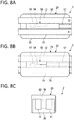
- the modification of Fig. 8 provides a temperature sensor 2 in which only one sensor intermediate body 50 is disposed between the first coil element 11 and the second coil element 12 as illustrated in FIGS. 8A to 8C .
- the temperature sensor 2 is in common with the temperature sensor 1 in that the one sensor assembly 20 holds both of the first coil element 11 and the second coil element 12.
- the temperature sensor 2 is influenced by two temperatures of temperature T1 of the first coil element 11 and temperature T2 of the second coil element 12. Therefore, detection temperature Td appears as an average value ((T1 + T2)/2) of the temperature T1 and the temperature T2.
- the detection temperature Td is also within the temperature range ⁇ Tn.
- the detection temperature Td is also deviated from the temperature range ⁇ Tn.
- the temperature sensor 2 can detect abnormality of the heat generation temperature of one or both of the first coil element 11 and the second coil element 12 even though the temperature sensor 2 includes one sensor intermediate body 50, namely, only one thermosensitive body 54. This makes it possible to suppress its cost.
- the sensor intermediate body 50 is interposed between the first coil element 11 and the second coil element 12, and serves as the partition 33 of the temperature sensor 1. This makes it possible to eliminate installation of the partition 33. Accordingly, it is possible to suppress the dimension of the temperature sensor 2 in the width direction W.
- the view windows 78 and 79 are provided in the P1609-EP second housing 70 including the resin molded body; however, the present invention is not limited thereto.
- the view windows 78 and 79 may be provided in the first housing 30 that is previously prepared as an injection molded product, or may be provided in both of the first housing 30 and the second housing 70.
- the view windows 78 and 79 are formed at a time when the first housing 30 is formed through injection molding.
- the covering body 60 is optional in the present invention, and the covering body 60 may include other transparent resin material, or may not be provided.
- the element main body 53 of the first sensor intermediate body 51 is opposite in direction to the element main body 53 of the second sensor intermediate body 52.
- the present invention is not limited thereto, and the element main body 53 of the first sensor intermediate body 51 and the element main body 53 of the second sensor intermediate body 52 may be provided in the same direction.
Landscapes
- Engineering & Computer Science (AREA)
- Physics & Mathematics (AREA)
- Power Engineering (AREA)
- General Physics & Mathematics (AREA)
- Microelectronics & Electronic Packaging (AREA)
- Nonlinear Science (AREA)
- Measuring Temperature Or Quantity Of Heat (AREA)
Description
- The present invention relates to a temperature sensor suitable for detecting, for example, temperature of a stator coil of a stator in a rotating machine.
- Temperature of a stator coil provided in a stator of a rotating machine is increased when a current flows through the stator coil. To avoid excessive temperature increase of the stator coil to stably operate the rotating machine, the temperature of the stator coil is detected with use of a temperature sensor. In the following, the stator coil is also simply referred to as a coil.
-
Patent Literature 1 provides a temperature sensor that makes it possible to prevent positional displacement of a temperature detection element while suppressing stress applied to the temperature detection element. The temperature sensor includes a first holder fixed to a coil element and including a housing chamber that houses a thermosensitive body of the temperature detection element, and a second holder fixed to the coil element to prevent positional displacement relative to the first holder and holding a lead wire of the temperature detection element. A part of the thermosensitive body exposed from the housing chamber comes into contact with a surface of the coil element. The coil element is electrically connected to the coil of the rotating machine. - The temperature sensor disclosed in
Patent Literature 1 covers and hides the thermosensitive body including the first holder and the second holder, with a resin mold. - Patent Literature 1:
JP 2017-26521 A - Furthermore,
JP 2017 026521 A WO 2016 120929 A1 disclose respective temperature sensors for coilelements, where one sensor is provided within one housing. - In the rotating machine, it is desirable to detect temperature of two different coils in some cases. The temperature sensor disclosed in
Patent Literature 1 has a reasonable dimension in an upright direction because the thermosensitive body stands upright on a thermosensitive surface of the coil element. For example, assuming the rotating machine of an electric vehicle, however, a space for the temperature sensor is not sufficient around the rotating machine. Therefore, it is not possible to provide two temperature sensors disclosed inPatent Literature 1 in some cases. - Accordingly, an object of the present invention is to provide a temperature sensor that makes it possible to save a space necessary for measurement of temperature of two coils.
- The above object is achieved by a temperature sensor according to
claim 1. The dependent claims are directed to different advantageous aspects of the invention. - According to a
temperature sensor 1 of the present invention, the first coil element and the second coil element are consolidated in onesensor assembly 20. This makes it possible to save an occupied space, as compared with a case where separate sensor assemblies are provided for the first coil element and the second coil element. -
- [
FIG. 1] FIG. 1 is a perspective view illustrating a temperature sensor according to an embodiment of the present invention. - [
FIGS. 2A and 2B] FIGS. 2A and 2B each illustrate the temperature sensor according to the present embodiment,FIG. 2A being a plan view, andFIG. 2B being a bottom view. - [
FIGS. 3A and 3B] FIGS. 3A and 3B each illustrate the temperature sensor according to the present embodiment,FIG. 3A being a front view, andFIG. 3B being a rear view. - [
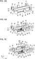
FIGS. 4A to 4C] FIGS. 4A to 4C are perspective views illustrating a procedure of manufacturing the temperature sensor according to the present embodiment,FIG. 4A illustrating a single first housing, andFIGS. 4B and 4C illustrating a state where sensor intermediate bodies are sequentially assembled to the first housing. - [
FIGS. 5A to 5C] FIGS. 5A to 5C are perspective views illustrating the procedure of manufacturing the temperature sensor according to the present embodiment followingFIGS. 4A to 4C ,FIGS. 5A and 5B illustrating a state where coil elements are sequentially assembled to the first housing, andFIG. 5C illustrating a state after a second housing is molded by a resin mold. - [
FIGS. 6A and 6B] FIGS. 6A and 6B are perspective views illustrating the sensor intermediate body included in the temperature sensor ofFIG. 1 ,FIG. 6A illustrating an outer shape thereof, andFIG. 6B illustrating an inside thereof in a transparent manner. - [
FIGS. 7A to 7D] FIGS. 7A to 7D are diagrams each illustrating a first modification in which a position of a thermosensitive body according to the present embodiment is changed. - [
FIGS. 8A to 8C] FIGS. 8A to 8C each illustrate a temperature sensor according to a second modification, not covered by the present claims,FIG. 8A being a plan view illustrating the temperature sensor from which a second housing is removed,FIG. 8B being a plan view, andFIG. 8C being a side view. - [
FIG. 9] FIG. 9 is a perspective view illustrating a temperature sensor in a comparative example in which sensor assemblies are individually provided for each of two coil elements. - An embodiment of the present invention is described below with reference to accompanying drawings.
- As illustrated in
FIG. 1 ,FIGS. 3A and 3B , atemperature sensor 1 according to the present embodiment includes a coil element 10 (first coil element 11 and second coil element 12) and asensor assembly 20 to be fixed to thecoil element 10. A thermosensitive body 54 (FIG. 6B ) included in thesensor assembly 20 detects temperature of thecoil element 10. Thecoil element 10 includes a rectangular cross-section. - In the
temperature sensor 1, thecoil element 10 is electrically connected to a coil configuring a stator of a rotating machine not illustrated, to configure a part of the coil, and thesensor assembly 20 detects the temperature of thecoil element 10 to detect temperature of the coil of the rotating machine. - In the
temperature sensor 1, the two coil elements of thefirst coil element 11 and thesecond coil element 12 are fixed to onesensor assembly 20, which achieves effects of space saving and excellent vibration resistance. - In the following, a configuration of the
temperature sensor 1 is sequentially described, and the effects of thetemperature sensor 1 are thereafter described. - The
coil element 10 configures, together with thesensor assembly 20, thetemperature sensor 1. - In the present embodiment, as illustrated in
FIG. 1 , thecoil element 10 includes the two coil elements of thefirst coil element 11 and thesecond coil element 12. Thefirst coil element 11 and thesecond coil element 12 are different in installation positions in thesensor assembly 20 but have the same configuration. Accordingly, the configuration of thefirst coil element 11 is described below as an example. - As illustrated in
FIG. 1 , thefirst coil element 11 includes a rectangular wire that includes aconductor 15 and an electrically insulatingcovering 17 that covers a surface of theconductor 15. - The
first coil element 11 includes a detection surface 16 (FIGS. 5A and 5B ) comprising a flat surface, and thedetection surface 16 comes into surface contact with a detection surface 65 (FIG. 6A ) of a coveringbody 60 inside ahousing 25. - In the
first coil element 11, both ends of theconductor 15 are electrically connected to the coil that configures the stator of the rotating machine as an electric apparatus, thereby serving as a part of a stator coil. - The
first coil element 11 is housed in and held by thehousing 25 except for the both ends. - Note that, in the following, the
first coil element 11 and thesecond coil element 12 are collectively referred to as thecoil element 10 when it is unnecessary to distinguish thefirst coil element 11 and thesecond coil element 12. - As illustrated in
FIG. 1 , thesensor assembly 20 includes thehousing 25 and a sensor intermediate body 50 (FIGS. 6A and 6B ) that is housed in thehousing 25. Thehousing 25 includes afirst housing 30 and asecond housing 70, and covers and hides the sensorintermediate body 50. Thesecond housing 70 includes a resin molded body that is previously formed through injection molding with respect to thefirst housing 30 housing thecoil element 10 and the sensorintermediate body 50. Note that, as illustrated inFIG. 4C , the sensorintermediate body 50 includes a first sensorintermediate body 51 and a second sensorintermediate body 52. - In the
sensor assembly 20, when thecoil element 10 is fixed to a predetermined position, thethermosensitive body 54 is positioned at a predetermined position on thedetection surface 16 of thecoil element 10. - As illustrated in
FIG. 4A , thefirst housing 30 includes afirst holding groove 31 and asecond holding groove 32 that penetrate through thefirst housing 30 in a longitudinal direction L. Thefirst holding groove 31 holds thefirst coil element 11 and the first sensorintermediate body 51, and thesecond holding groove 32 holds thesecond coil element 12 and the second sensorintermediate body 52. - The
first housing 30 is integrally molded through injection molding of an electrically insulating resin material. As the resin material, for example, polyphenylene sulfide (PPS) resin and polyamide (PA) resin may be used. Thesecond housing 70 is made from the same resin material. The resin material configuring thefirst housing 30 and thesecond housing 70 has rigidity higher than rigidity of a fluorine resin configuring the coveringbody 60 that covers a part of the sensorintermediate body 50. Accordingly, thesensor assembly 20 is firmly fixed to thecoil element 10. - As illustrated in
FIG. 4A , thefirst housing 30 includes apartition 33 between the first holdinggroove 31 and thesecond holding groove 32. Thepartition 33 electrically insulates thefirst coil element 11 and thesecond coil element 12 from each other. - The
first housing 30 includes abottom floor 34 and sixsupporters bottom floor 34. Thesupporters partition 33 with the first holdinggroove 31 in between. In addition, thesupporters partition 33 with thesecond holding groove 32 in between. - The
supporters first housing 30 in a width direction W. A view window 78 (FIG. 3A ) described later is disposed between thesupporter 35 and thesupporter 36. - Further, the
supporters first housing 30 in the width direction W. A view window 79 (FIG. 3B ) described later is disposed between thesupporter 39 and thesupporter 41. - As illustrated in
FIG. 4A , thesupporter 35 and thesupporter 41 are respectively provided at one end and the other end of thefirst housing 30 in the longitudinal direction L. - The
supporter 35 abuts on thefirst coil element 11 housed in the first holdinggroove 31, thereby supporting thefirst coil element 11 together with thepartition 33 in the width direction W. In addition, thesupporter 36 abuts on the first sensorintermediate body 51 housed in the first holdinggroove 31, thereby supporting the first sensorintermediate body 51 together with thesupporter 37. - The
supporter 41 is different in position from thesupporter 35 but acts to support the second sensorintermediate body 52 in a similar manner. Therefore, further description of thesupporter 41 is omitted. - As illustrated in
FIG. 4A , thesupporter 37 is provided at one end and the other end of thefirst housing 30 in the longitudinal direction L. - Each of the
supporter 37 and thesupporter 38 includes electricwire holding holes wires intermediate body 51 are respectively inserted. The electricwire holding holes supporter 37 and thesupporter 38 in the longitudinal direction L. - The
supporter 38 is different in position from thesupporter 37 but acts to support the second sensorintermediate body 52 in a similar manner. Therefore, further description of thesupporter 38 is omitted. - As illustrated in
FIG. 4A , thesupporter 36 is provided between thesupporter 35 and thesupporter 37. Thesupporter 36 supports, together with thepartition 33, the sensorintermediate body 50 and thecoil element 10 in the width direction W. - The
supporter 39 is different in position from thesupporter 36 but acts to support the second sensorintermediate body 52 in a similar manner. Therefore, further description of thesupporter 39 is omitted. - As illustrated in
FIG. 4A , thefirst housing 30 includes agap 45 between thesupporter 35 and thesupporter 36, and agap 46 between thesupporter 36 and thesupporter 37. In addition, thefirst housing 30 includes agap 47 between thesupporter 38 and thesupporter 39, and agap 48 between thesupporter 39 and thesupporter 41. - As illustrated in
FIGS. 3A and 3B , afirst locking part 74, asecond locking part 75, athird locking part 76, and afourth locking part 77 of thesecond housing 70 are respectively buried in thegaps view windows part 74 and the fourth lockingpart 77. - As illustrated in
FIG. 6B , the first sensorintermediate body 51 includes an elementmain body 53, a pair ofextraction wires wires extraction wires main body 53. Thelead wires extraction wires intermediate body 52 includes a configuration similar to the configuration of the first sensorintermediate body 51, and therefore description of the second sensorintermediate body 52 is omitted. Note that the elementmain body 53 included in the first sensorintermediate body 51 corresponds to a first element main body of the present invention, and the elementmain body 53 included in the second sensorintermediate body 52 corresponds to a second element main body of the present invention. - The element
main body 53 is a cylindrical member that includes thethermosensitive body 54 having temperature characteristics in electric resistance, and a sealingglass 55 covering surroundings of thethermosensitive body 54. - The
thermosensitive body 54 includes, for example, a material having temperature characteristics in electric resistance, like a thermistor. - The sealing
glass 55 is provided to seal and maintain thethermosensitive body 54 in an airtight state, thereby preventing chemical change and physical change based on an environmental condition from occurring on thethermosensitive body 54. Amorphous glass and crystalline glass are both usable as the sealingglass 55, or the amorphous glass and the crystalline glass are mixed so as to have a desired linear expansion coefficient and such a mixture may be used as the sealingglass 55. - The
extraction wires thermosensitive body 54 through an unillustrated electrode. The Dumet wire includes an inner layer and an outer layer provided around the inner layer. The inner layer contains an iron-nickel alloy having a linear expansion coefficient close to that of glass, and the outer layer is cladded with copper or a copper alloy having high electroconductivity. - In addition, each of the
lead wires insulating covering layer 58 covering the twisted wire, and is bonded to thecorresponding extraction wire 56 through welding. Thelead wires - In addition, as illustrated in
FIGS. 6A and 6B , in the first sensorintermediate body 51, the whole of the elementmain body 53 and theextraction wires lead wires body 60, and the elementmain body 53 is protected from the surrounding environment. - The covering
body 60 includes a substantially rectangular parallelepiped shape, and includes aninner layer 61 and anouter layer 63. - The
inner layer 61 is disposed inside theouter layer 63, and directly covers the elementmain body 53. Theinner layer 61 air-tightly seals a portion from a front end of the elementmain body 53 to the middle of thelead wires - The
inner layer 61 is formed of a fluorine resin containing a tetrafluoroethylene-perfluoroalkylvinylether copolymer (PFA). The PTFE forming theouter layer 63 and the PFA are fluorine resins and have excellent resistance in common; however, the PTFE has a melting point higher than that of the PFA. In addition, the PTFE and the PFA both include transparency, and in particular, the PFA include high transparency. - Further, the
outer layer 63 is provided in close contact with outside of theinner layer 61. - The
outer layer 63 provides, together with theinner layer 61, resistance to the elementmain body 53, and holds theinner layer 61 that is melted in a manufacturing process. Accordingly, theouter layer 63 contains the PTFE that has a melting point higher than that of the PFA forming theinner layer 61. - The
outer layer 63 includes theflat detection surface 65, and thedetection surface 65 comes into contact with theflat detection surface 16 of thecoil element 10. As a result, the coveringbody 60 and thecoil element 10 come into surface contact with each other. - The covering
body 60 is fabricated by preparing an inner layer tube corresponding to theinner layer 61 and an outer layer tube corresponding to theouter layer 63, inserting the elementmain body 53 into the inner layer tube and disposing the outer layer tube on the outside of the inner layer tube, and performing heating and pressurization. - The melting point of the PFA configuring the inner layer tube is 302°C to 310°C whereas the melting point of the PTFE configuring the outer layer tube is 327°C. Therefore, if both are heated to, for example, 315°C, the inner layer tube is melted but the outer layer tube is not melted and can maintain its shape. The outer layer tube, however, contracts when heated to this temperature. The PTFE includes a linear expansion coefficient of about 10×10-5/°C, and strongly compresses the inner layer tube in the melted state. This contributes to densification of the
inner layer 61, and airtightness between theinner layer 61 and theouter layer 63 is secured by pressure generated therebetween. - Press working is performed with use of a mold having a rectangular parallelepiped cavity while the inner layer tube is melted, which results in the rectangular
parallelepiped covering body 60. - In the present embodiment, a transparent fluorine resin is used as the covering
body 60. This allows for visual confirmation of soundness of the elementmain body 53 buried inside the coveringbody 60 through the view window 78 (79). In addition, the fluorine resin is rich in elasticity as compared with other resin materials. Accordingly, even if thecoil element 10 as a temperature detection object vibrates, the coveringbody 60 follows the vibration and is tightly pressed against thecoil element 10. - As illustrated in
FIG. 1 andFIG. 3A , thesecond housing 70 covers and hides thecoil element 10 and the sensorintermediate body 50 that are housed in thefirst housing 30, from a thickness direction T, and holds, together with thefirst housing 30, thecoil element 10 and the sensorintermediate body 50. - As illustrated in
FIGS. 3A and 3B andFIG. 4A , thesecond housing 70 includes abase part 71 that covers and hides the first holdinggroove 31 and thesecond holding groove 32. In addition, thesecond housing 70 includes the first lockingpart 74 and thesecond locking part 75. Thefirst locking part 74 communicates with thebase part 71 and fills thegap 45 between thesupporter 35 and thesupporter 36. Thesecond locking part 75 communicates with thebase part 71 and fills thegap 46 between thesupporter 36 and thesupporter 37. Further, thesecond housing 70 includes thethird locking part 76 and the fourth lockingpart 77. Thethird locking part 76 communicates with thebase part 71 and fills thegap 47 between thesupporter 38 and thesupporter 39. Thefourth locking part 77 communicates with thebase part 71 and fills thegap 48 between thesupporter 39 and thesupporter 41. - As illustrated in
FIGS. 2A, 2B andFIGS. 3A, 3B , thebase part 71, the first lockingpart 74, thesecond locking part 75, thethird locking part 76, and the fourth lockingpart 77 that are integrally formed are locked in thefirst housing 30. Therefore, thesecond housing 70 is firmly fixed to thefirst housing 30 so as not to be displaced in position from each other. - As illustrated in
FIGS. 3A and 3B , thesecond housing 70 includes theview window 78 in the first lockingpart 74, and theview window 79 in the fourth lockingpart 77. - The
view window 78 penetrates front and rear surfaces of the first lockingpart 74, and is provided corresponding to a position at which thethermosensitive body 54 to be housed in the first holdinggroove 31 is disposed. The elementmain body 53 is covered with the coveringbody 60. The coveringbody 60, however, has high transparency, and accordingly, thethermosensitive body 54 and the sealingglass 55 are visually confirmed through theview window 78. In addition, a bonded part of theextraction wire 56 and thelead wire 57 through welding is also visually confirmed through theview window 78. As described above, theview window 78 is open corresponding to a range allowing for visual confirmation of a portion from thethermosensitive body 54 to the bonded part. Theview window 79 is provided in a similar manner, and thethermosensitive body 54, the sealingglass 55, and the like are visually confirmable through theview window 79. - Next, a procedure of manufacturing the
temperature sensor 1 is described with reference toFIG. 4A andFIG. 5C . - As illustrated in
FIG. 4A , thefirst housing 30 fabricated through injection molding is prepared. Thefirst housing 30 waits for next work in a state where the first holdinggroove 31 and thesecond holding groove 32 face upward. - First, as illustrated in
FIG. 4B and FIG. 4C , the first sensorintermediate body 51 is housed in the first holdinggroove 31 and the second sensorintermediate body 52 is housed in thesecond holding groove 32 in order in the preparedfirst housing 30. - The first sensor
intermediate body 51 is housed in the first holdinggroove 31 such that thelead wires wire holding holes supporter 37. When thelead wires wire holding holes body 60 abuts on the supporting surface of each of thesupporter 36 and thesupporter 37, the first sensorintermediate body 51 is positioned at a predetermined position of the first holdinggroove 31. - The second sensor
intermediate body 52 is also positioned at a predetermined position of thesecond holding groove 32 in a similar manner. - Note that, in the
first housing 30, side provided with the first sensorintermediate body 51 is referred to as front side, and side provided with the second sensorintermediate body 52 is referred to as inner side. - As illustrated in
FIG. 4C , the first holdinggroove 31 on the inner side from the first sensorintermediate body 51 in the width direction W includes, between the first sensorintermediate body 51 and thepartition 33, a space housing thefirst coil element 11. In addition, as illustrated inFIG. 4C , thesecond holding groove 32 on the front side of the second sensorintermediate body 52 includes, between the second sensorintermediate body 52 and thepartition 33, a space housing thesecond coil element 12. - After the first sensor
intermediate body 51 and the second sensorintermediate body 52 are housed at the respective predetermined positions of thefirst housing 30, thefirst coil element 11 and thesecond coil element 12 are then respectively housed in the spaces of the first holdinggroove 31 and thesecond holding groove 32 as illustrated inFIG. 5A and FIG. 5B . - Dimensions of each of the first holding
groove 31 of thefirst housing 30, thepartition 33, the coveringbody 60 of the first sensorintermediate body 51, and thefirst coil element 11 are set to house thefirst coil element 11 in the corresponding space without a gap. Thesecond coil element 12 is housed in a similar manner. - The
first coil element 11 housed in the first holdinggroove 31 is in parallel to the first sensorintermediate body 51, and thesecond coil element 12 housed in thesecond holding groove 32 is in parallel to the second sensorintermediate body 52. - Further, the
first coil element 11 and thesecond coil element 12 respectively include afirst counter surface 13 and asecond counter surface 14 that face each other. The first sensorintermediate body 51 is disposed on rear side of thefirst counter surface 13 of thefirst coil element 11, and the second sensorintermediate body 52 is disposed on rear side of thesecond counter surface 14 of thesecond coil element 12. Accordingly, thethermosensitive body 54 of the first sensorintermediate body 51 is hardly influenced by heat generation of thesecond coil element 12, and thethermosensitive body 54 of the second sensorintermediate body 52 is hardly influenced by heat generation of thefirst coil element 11. Accordingly, thethermosensitive bodies first coil element 11 and thesecond coil element 12, relative to the side (inner side) on which thefirst coil element 11 and thesecond coil element 12 face each other. - Assuming that the
temperature sensor 1 is used in an environment in which vibration is applied to thetemperature sensor 1, a slight interference is provided between the space and thefirst coil element 11. As a result, fitting thefirst coil element 11 into the space causes thefirst coil element 11 and the first sensorintermediate body 51 to press against each other. This generates resistance to the vibration. This is true of thesecond coil element 12. - The
first coil element 11 and thesecond coil element 12 each have dimensions in the longitudinal direction L larger than the dimensions of thefirst housing 30, and are respectively housed in the first holdinggroove 31 and thesecond holding groove 32 such that both end of each of thefirst coil element 11 and thesecond coil element 12 project from thefirst housing 30. - When a surface as a temperature detection object of the
first coil element 11 comes into contact with the coveringbody 60 of the first sensorintermediate body 51 on the front side in the width direction W, and also abuts on thesupporter 35 and thesupporter 37, thefirst coil element 11 is held at the predetermined position in thefirst housing 30. - In addition, when a surface as the temperature detection object of the
second coil element 12 comes into contact with the coveringbody 60 of the second sensorintermediate body 52 on the inner side in the width direction W, and also abuts on thesupporter 38 and thesupporter 41, thesecond coil element 12 is held at the predetermined position in thefirst housing 30. - After the
first coil element 11 and thesecond coil element 12 are held by thefirst housing 30, thesecond housing 70 is molded through injection molding as illustrated inFIG. 5C . In molding of thesecond housing 70 by a resin mold, thethermosensitive body 54 including the sealingglass 55 receives considerable pressure, which may cause breakage of thethermosensitive body 54. - The
second housing 70 is formed such that the first holdinggroove 31 and thesecond holding groove 32 of thefirst housing 30 are sealed from the outside, and thecoil element 10 and the sensorintermediate body 50 housed in the first holdinggroove 31 and thesecond holding groove 32 are covered with and hidden by thesecond housing 70. This prevents thethermosensitive body 54 from being thermally influenced by any part other than thecoil element 10, and strengthens the fixing of thecoil element 10 and the sensorintermediate body 50. - The
second housing 70 is formed to include theview window 78 in the first lockingpart 74 and theview window 79 in the fourth lockingpart 77. - The
view window 78 penetrates the front and rear surfaces of the first lockingpart 74, which allows for visual confirmation of the coveringbody 60 of the first sensorintermediate body 51 from the outside. Theview window 78 is provided at a position corresponding to thethermosensitive body 54 of the first sensorintermediate body 51. - The
view window 79 penetrates the front and rear surfaces of the fourth lockingpart 77, which allows for visual confirmation of the coveringbody 60 of the second sensorintermediate body 52 from the outside. Theview window 79 is provided at a position corresponding to thethermosensitive body 54 of the second sensorintermediate body 52. - Effects achieved by the
temperature sensor 1 are described below. - In the
temperature sensor 1, thefirst coil element 11 and thesecond coil element 12 are fixed by the onesensor assembly 20 that includes the first sensorintermediate body 51 and the second sensorintermediate body 52 respectively detecting temperature of thefirst coil element 11 and thesecond coil element 12. - For example, as illustrated in
FIG. 9 , afirst sensor assembly 121 may be provided for afirst coil element 111, and asecond sensor assembly 122 may be provided for asecond coil element 112. In the following, the mode illustrated inFIG. 9 is referred to as a comparative example. When two assemblies of thefirst sensor assembly 121 and thesecond sensor assembly 122 are individually provided as separated bodies as with the comparative example, however, the space occupied by the sensor assemblies is accordingly increased. - In contrast, the
temperature sensor 1 includes the first sensorintermediate body 51 and the second sensorintermediate body 52 consolidated in onesensor assembly 20. This makes it possible to reduce the space occupied by the sensor assembly, as compared with the case where two sensor assemblies are provided separately. - As for reduction of the occupied space, the dimension in the width direction W or the height direction T may be suppressed since the first sensor
intermediate body 51 is in parallel to thefirst coil element 11, and the second sensorintermediate body 52 is in parallel to thesecond coil element 12 in thetemperature sensor 1. - In addition, consolidation to one
sensor assembly 20 as with thetemperature sensor 1 is advantageous to vibration as compared with the case where twosensor assemblies - In other words, in the
temperature sensor 1, thesensor assembly 20 fixes the two coil elements of thefirst coil element 11 and thesecond coil element 12 at one position. This makes it possible to suppress vibration as compared with the case where thesensor assemblies temperature sensor 1 may be suppressed in the entire weight because thefirst coil element 11 and thesecond coil element 12 are consolidated in onesensor assembly 20, as compared with the case where thesensor assembly 121 and thesensor assembly 122 are separately provided. This also makes it possible to suppress vibration. - Moreover, consolidation to one
sensor assembly 20 as with the present embodiment is advantageous to selection of a position at which the temperature is detected, as compared with the case where the two sensor assemblies are separately provided. In the case where the temperature of the coil of the rotating machine is detected, it is desirable to detect a part where heat is generated most intensely, for the purpose. - In the case where the
first sensor assembly 121 and thesecond sensor assembly 122 are separately provided as with the comparative example illustrated inFIG. 9 , thefirst coil element 111 and thesecond coil element 112 are provided while being displaced in position in the longitudinal direction L because of the space around the rotating machine to which the two sensor assemblies are assembled. Accordingly, if one of the sensor assemblies, for example, thefirst sensor assembly 121 is disposed at the part where heat is generated most intensely, thesecond sensor assembly 122 is inevitably displaced from the part. - In contrast, the
temperature sensor 1 includes onesensor assembly 20 consolidated into one place, which makes it possible to bring thethermosensitive body 54 of each of the first sensorintermediate body 51 and the second sensorintermediate body 52 close to the part. Accordingly, it is possible to detect the temperature of the part where the heat is generated most intensely by the correspondingthermosensitive body 54. - Moreover, in the
temperature sensor 1, it is possible to assemble the onesensor assembly 20 to thefirst coil element 11 and thesecond coil element 12 by single operation. This allows for reduction of man-hours as compared with the case where the one sensor assembly is assembled to one coil element as with the comparative example. - Further, in the
temperature sensor 1, thethermosensitive body 54 corresponding to thefirst coil element 11 is disposed outside thefirst coil element 11, and thethermosensitive body 54 corresponding to thesecond coil element 12 is disposed outside thesecond coil element 12. As described above, thethermosensitive body 54 corresponding to thefirst coil element 11 is far from thesecond coil element 12. Therefore, thethermosensitive body 54 corresponding to thefirst coil element 11 is not influenced by the heat generation of thesecond coil element 12, and accurately detects the temperature of thefirst coil element 11. Likewise, thethermosensitive body 54 corresponding to thesecond coil element 12 also accurately detects the temperature of thesecond coil element 12. In addition, since thepartition 33 is provided between thefirst coil element 11 and thesecond coil element 12, it is possible to further suppress influence of the heat generation. - Moreover, according to the
temperature sensor 1, theview window 78 is provided at the position corresponding to a range that includes thethermosensitive body 54 and the bonded parts of theextraction wires 56 and thelead wires 57 through welding, and theview window 79 is provided at the position corresponding to a range that includes thethermosensitive body 54 and the bonded parts of theextraction wires 56 and thelead wires 57 through welding of the first sensorintermediate body 51 and the second sensorintermediate body 52. This allows for visual confirmation of soundness of thethermosensitive body 54 including the sealingglass 55 from the outside even after thesecond housing 70 is formed. Therefore, according to thetemperature sensor 1, it is possible to detect a defectivethermosensitive body 54 after thesecond housing 70 is formed and to eliminate thetemperature sensor 1. - In addition, the element
main body 53 including thethermosensitive body 54 is covered with thetransparent covering body 60 in thetemperature sensor 1, which allows for visual confirmation of the soundness of thethermosensitive body 54 while protecting the elementmain body 53. - In addition, since the
flat detection surface 65 of the coveringbody 60 and theflat detection surface 16 of each of thefirst coil element 11 and thesecond coil element 12 come into surface contact with each other in thetemperature sensor 1, sensitivity with respect to temperature variation of thecoil element 10 is enhanced, which contributes to accuracy improvement of the detection temperature. - In particular, the covering
body 60 including the fluorine resin is rich in elasticity among resin materials. Therefore, even if thecoil element 10 as the temperature detection object vibrates, the coveringbody 60 follows the vibration and is tightly pressed against thecoil element 10. This contributes to accuracy improvement of the detection temperature. - In addition, since the covering
body 60 is rich in elasticity, it is advantageous to provide theview windows second housing 70. In other words, to form theview windows view windows body 60 housed in the first holdinggroove 31. - If contact force of the mold and the covering
body 60 is weak, the melted resin configuring thesecond housing 70 enters between the mold and the coveringbody 60 and covers theview windows thermosensitive body 54. - Even if the contact force of the mold and the covering
body 60 is strong, the coveringbody 60 according to the present embodiment is not broken because the coveringbody 60 is rich in elasticity. For example, if the coveringbody 60 contains a resin material similar to that of thesecond housing 70, the coveringbody 60 may be broken when the contact force of the mold and the coveringbody 60 is increased. Therefore, it is necessary to strictly adjust the contact force of the mold and the coveringbody 60. - According to the present embodiment, such adjustment is unnecessary because the covering
body 60 is rich in elasticity. This facilitates manufacturing of thetemperature sensor 1. - In addition, in the
temperature sensor 1, thelead wires main body 53 are respectively inserted into the electricwire holding holes first housing 30 and are held by thesupporter 37. Thelead wires supporter 37 at a time when the elementmain body 53 is housed in thefirst housing 30. Accordingly, the positions of theextraction wires lead wires second housing 70 is performed thereafter. Therefore, the melted resin does not damage thelead wires lead wires first housing 30. - The
temperature sensor 1 according to the present embodiment includes the first sensorintermediate body 51 disposed on the front side and the second sensorintermediate body 52 disposed on the inner side in the width direction W. The arrangement of the first sensor intermediate body 51 (thermosensitive body 54) and the second sensor intermediate body 52 (thermosensitive body 54) in the present invention, however, is not limited thereto. - In other words, as illustrated in
FIG. 7A , the correspondingthermosensitive body 54 may be provided on an upper side of thefirst coil element 11 and on upper side of thesecond coil element 12. Further, as illustrated inFIG. 7B , the correspondingthermosensitive body 54 may be provided on a lower side of thefirst coil element 11 and on lower side of thesecond coil element 12. Furthermore, as illustrated inFIG. 7C , the correspondingthermosensitive body 54 may be provided on the upper side of thefirst coil element 11 and on the lower side of thesecond coil element 12. - Note that
FIGS. 7A to 7C each illustrate only the positional relationship of thefirst coil element 11, thesecond coil element 12, and thethermosensitive bodies 54. In addition,FIG. 7B illustrates the positional relationship thereof in the above-describedtemperature sensor 1. - As described above, the two
thermosensitive bodies first coil element 11 and thesecond coil element 12 except for thefirst counter surface 13 and thesecond counter surface 14 that face each other. Moreover, thethermosensitive bodies temperature sensor 1 is assembled. - In this case, in the
housing 25 of thetemperature sensor 1, a boundary between thefirst housing 30 and thesecond housing 70 extends along a direction (referred to as lateral direction) in which thefirst coil element 11 and thesecond coil element 12 face each other. In the present invention, however, the boundary between thefirst housing 30 and thesecond housing 70 may extend along a vertical direction orthogonal to the lateral direction. - The
temperature sensor 1 according to the present embodiment includes the first sensorintermediate body 51 and the second sensorintermediate body 52 that respectively correspond to thefirst coil element 11 and thesecond coil element 12, and individually detects the temperature of thefirst coil element 11 and the temperature of thesecond coil element 12 as an assumption. The modification ofFig. 8 provides atemperature sensor 2 in which only one sensorintermediate body 50 is disposed between thefirst coil element 11 and thesecond coil element 12 as illustrated inFIGS. 8A to 8C . Thetemperature sensor 2 is in common with thetemperature sensor 1 in that the onesensor assembly 20 holds both of thefirst coil element 11 and thesecond coil element 12. - The
temperature sensor 2 is influenced by two temperatures of temperature T1 of thefirst coil element 11 and temperature T2 of thesecond coil element 12. Therefore, detection temperature Td appears as an average value ((T1 + T2)/2) of the temperature T1 and the temperature T2. - When the temperature T1 and the temperature T2 are both within a normal temperature range ΔTn, the detection temperature Td is also within the temperature range ΔTn. For example, if one or both of the temperature T1 and the temperature T2 are deviated from the temperature range ΔTn, the detection temperature Td is also deviated from the temperature range ΔTn.
- Accordingly, the
temperature sensor 2 can detect abnormality of the heat generation temperature of one or both of thefirst coil element 11 and thesecond coil element 12 even though thetemperature sensor 2 includes one sensorintermediate body 50, namely, only onethermosensitive body 54. This makes it possible to suppress its cost. - In addition, in the
temperature sensor 2, the sensorintermediate body 50 is interposed between thefirst coil element 11 and thesecond coil element 12, and serves as thepartition 33 of thetemperature sensor 1. This makes it possible to eliminate installation of thepartition 33. Accordingly, it is possible to suppress the dimension of thetemperature sensor 2 in the width direction W. - The preferred embodiment of the present invention has been described above.
- In addition, in the present embodiment, the example in which the
view windows second housing 70 including the resin molded body has been described; however, the present invention is not limited thereto. Theview windows first housing 30 that is previously prepared as an injection molded product, or may be provided in both of thefirst housing 30 and thesecond housing 70. - In this case, the
view windows first housing 30 is formed through injection molding. - Further, in the present embodiment, the example in which the most part of the element
main body 53 including thethermosensitive body 54 is covered with the coveringbody 60 including the fluorine resin has been described. The coveringbody 60, however, is optional in the present invention, and the coveringbody 60 may include other transparent resin material, or may not be provided. - Further, in the present embodiment, the element
main body 53 of the first sensorintermediate body 51 is opposite in direction to the elementmain body 53 of the second sensorintermediate body 52. The present invention, however, is not limited thereto, and the elementmain body 53 of the first sensorintermediate body 51 and the elementmain body 53 of the second sensorintermediate body 52 may be provided in the same direction. -
- 1, 2
- Temperature sensor
- 10
- Coil element
- 11
- First coil element
- 12
- Second coil element
- 15
- Conductor
- 16
- Detection surface
- 17
- Covering
- 20
- Sensor assembly
- 25
- Housing
- 30
- First housing
- 31
- First holding groove
- 32
- Second holding groove
- 33
- Partition
- 34
- Bottom floor
- 35, 36, 37
- Supporter
- 38, 39, 41
- Supporter
- 42
- Electric wire holding hole
- 45, 46, 47, 48
- Gap
- 50
- Sensor intermediate body
- 51
- First sensor intermediate body
- 52
- Second sensor intermediate body
- 53
- Element main body
- 54
- Thermosensitive body
- 55
- Sealing glass
- 56
- Extraction wire
- 57
- Lead wire
- 58
- Covering layer
- 60
- Covering body
- 61
- Inner layer
- 63
- Outer layer
- 65
- Detection surface
- 70
- Second housing
- 71
- Base part
- 74
- First locking part
- 75
- Second locking part
- 76
- Third locking part
- 77
- Fourth locking part
- 78, 79
- View window
- L
- Longitudinal direction
- W
- Width direction
- T
- Thickness direction
Claims (8)
- A temperature sensor, comprising:a first coil element (11) and a second coil element (12) both serving as a part of a coil (10) of an electric apparatus;a first element main body (53)configured to detect the temperature of the first coil element element (11)and a second element main body (53)configured to detect the temperature of the second coil element (12), each of the first element main body (53) and second element main body (53) respectively including a thermosensitive body (54) and a pair of electric wires (56, 57) connected to the thermosensitive body (54); a first electrically insulating covering body (60) that covers the thermosensitive body (54) and at least a part of the electric wires (56, 57) of the first element main body (53), and a second electrically insulating covering body (60) that covers the thermosensitive body (54)and at least a part of the electric wires (56, 57) of the second element main body (53);anda housing (25) that includes an electric insulating resin material, and is configured to house and hold the first coil element (11), the second coil element (12), the first element main body (53), the second element main body (53), the first covering body (60) and the second covering body (60), wherein the first covering body (60) and the first coil element (11) come into surface contact with each other, and the second covering body (60) and the second coil element (12) come into surface contact with each other, and wherein the first coil element (11) and the second coil element (12) each include a rectangular cross-section, and respectively include a first counter surface and a second counter surface that face each other,the first element main body is provided corresponding to any surface of the first coil element (11) other than the first counter surface, andthe second element main body is provided corresponding to any surface of the second coil element (12) other than the second counter surface.
- The temperature sensor according to claim 1, wherein
the first element main body is provided corresponding to a surface on a rear side of the first counter surface, and
the second element main body is provided corresponding to a surface on a rear side of the second counter surface. - The temperature sensor according to any one of claims 1 or 2, wherein the housing (25) includes a partition (33) that electrically insulates the first coil element (11) and the second coil element (12) from each other.
- The temperature sensor according to any one of claims 1 to 3, wherein the housing (25) includes, at a position corresponding to the thermosensitive body (54), a view window (78, 79) allowing for visual confirmation of the thermosensitive body (54) from outside.
- The temperature sensor according to claim 4, wherein
the housing (25) includes a first housing (30) and a second housing (70) both configuring the housing (25), and
the view window (78, 79) is provided on one or both of the first housing (30) and the second housing (70). - The temperature sensor according to claim 5, wherein
the second housing (70) includes a resin molded body with respect to the first housing (30), and
the view window (78, 79) is provided in the second housing (70). - The temperature sensor according to any one of claims 4 to 6, wherein the covering body (60) includes a transparent resin and closely covers the thermosensitive body (54) and a part of the electric wires (56, 57), wherein
the view window (78, 79) is provided at a position corresponding to the thermosensitive body (54) covered with the covering body (60). - The temperature sensor according to any one of claims 4 to 7, wherein
the view window (78, 79) is provided corresponding to each of the thermosensitive body (54) of the first element main body and the thermosensitive body (54) of the second element main body.
Priority Applications (1)
| Application Number | Priority Date | Filing Date | Title |
|---|---|---|---|
| EP21150486.5A EP3825668B1 (en) | 2017-04-11 | 2017-04-11 | Temperature sensor |
Applications Claiming Priority (1)
| Application Number | Priority Date | Filing Date | Title |
|---|---|---|---|
| PCT/JP2017/014848 WO2018189813A1 (en) | 2017-04-11 | 2017-04-11 | Temperature sensor |
Related Child Applications (2)
| Application Number | Title | Priority Date | Filing Date |
|---|---|---|---|
| EP21150486.5A Division EP3825668B1 (en) | 2017-04-11 | 2017-04-11 | Temperature sensor |
| EP21150486.5A Division-Into EP3825668B1 (en) | 2017-04-11 | 2017-04-11 | Temperature sensor |
Publications (3)
| Publication Number | Publication Date |
|---|---|
| EP3556872A1 EP3556872A1 (en) | 2019-10-23 |
| EP3556872A4 EP3556872A4 (en) | 2020-02-26 |
| EP3556872B1 true EP3556872B1 (en) | 2021-03-03 |
Family
ID=61231436
Family Applications (2)
| Application Number | Title | Priority Date | Filing Date |
|---|---|---|---|
| EP21150486.5A Active EP3825668B1 (en) | 2017-04-11 | 2017-04-11 | Temperature sensor |
| EP17859379.4A Active EP3556872B1 (en) | 2017-04-11 | 2017-04-11 | Temperature sensor |
Family Applications Before (1)
| Application Number | Title | Priority Date | Filing Date |
|---|---|---|---|
| EP21150486.5A Active EP3825668B1 (en) | 2017-04-11 | 2017-04-11 | Temperature sensor |
Country Status (5)
| Country | Link |
|---|---|
| US (1) | US10742093B2 (en) |
| EP (2) | EP3825668B1 (en) |
| JP (1) | JP6282791B1 (en) |
| CN (1) | CN109041578B (en) |
| WO (1) | WO2018189813A1 (en) |
Families Citing this family (22)
| Publication number | Priority date | Publication date | Assignee | Title |
|---|---|---|---|---|
| JP6419756B2 (en) * | 2016-06-23 | 2018-11-07 | 株式会社芝浦電子 | Temperature detection device |
| CN108885142B (en) * | 2017-03-16 | 2019-11-26 | 株式会社芝浦电子 | Temperature sensor |
| JP6652980B2 (en) * | 2018-02-26 | 2020-02-26 | 本田技研工業株式会社 | Stator, thermistor fixing structure and thermistor fixing method |
| JP6535428B1 (en) * | 2018-03-30 | 2019-06-26 | 株式会社芝浦電子 | Temperature sensing device and assembly |
| DE102018207229A1 (en) * | 2018-05-09 | 2019-11-14 | Volkswagen Aktiengesellschaft | Stator for an electric machine and method for manufacturing an electric machine |
| DE102018208384A1 (en) * | 2018-05-28 | 2019-11-28 | Zf Friedrichshafen Ag | Stator of an electric machine with a temperature sensor and electric machine with such a stator |
| CN111316079B (en) * | 2018-08-02 | 2024-01-30 | 株式会社芝浦电子 | Temperature detection device and assembly |
| DE102018221572A1 (en) * | 2018-12-12 | 2020-06-18 | Robert Bosch Gmbh | Temperature detection device of an electric motor |
| DE102019202912A1 (en) * | 2019-03-05 | 2020-09-10 | Zf Friedrichshafen Ag | Interconnection arrangement for a stator, temperature sensor device and system for detecting a temperature |
| DE102019112516A1 (en) * | 2019-05-14 | 2020-11-19 | Schaeffler Technologies AG & Co. KG | Temperature measuring device for a stator of an electrical machine with hairpin or rod wave windings |
| CN113950616B (en) * | 2019-10-10 | 2024-05-10 | 株式会社芝浦电子 | Temperature sensor and motor |
| JP7175251B2 (en) | 2019-10-25 | 2022-11-18 | 日立金属株式会社 | Temperature sensor and power distribution component with the same, motor with power distribution component |
| JP7415836B2 (en) * | 2020-08-04 | 2024-01-17 | 株式会社プロテリアル | Motor wiring member and its manufacturing method |
| US12301068B2 (en) * | 2021-03-01 | 2025-05-13 | Proterial, Ltd. | Physical quantity detection device |
| JP7567633B2 (en) * | 2021-04-06 | 2024-10-16 | 株式会社プロテリアル | Wiring components with physical quantity sensors |
| DE102021108495A1 (en) | 2021-04-06 | 2022-10-06 | Schaeffler Technologies AG & Co. KG | temperature sensor assembly |
| DE102021116111A1 (en) * | 2021-06-22 | 2022-12-22 | Tdk Electronics Ag | Measurement setup and holder |
| JP7212209B1 (en) * | 2022-03-03 | 2023-01-24 | 株式会社芝浦電子 | Temperature sensor, assembly, rotary electric machine, and temperature sensor manufacturing method |
| JP7329653B1 (en) | 2022-04-11 | 2023-08-18 | 三菱電機株式会社 | Stator and rotary electric machine using the same |
| CN118960983A (en) * | 2022-05-25 | 2024-11-15 | 株式会社芝浦电子 | Temperature sensor and heating cooker |
| DE102024101700A1 (en) * | 2024-01-22 | 2025-07-24 | Te Connectivity Solutions Gmbh | Temperature sensor for a high-voltage conductor and manufacturing method of such a temperature sensor |
| WO2025183113A1 (en) * | 2024-02-27 | 2025-09-04 | ニデック株式会社 | Temperature detection device, coil, transformer, and temperature detection method |
Family Cites Families (10)
| Publication number | Priority date | Publication date | Assignee | Title |
|---|---|---|---|---|
| JP2004354239A (en) * | 2003-05-29 | 2004-12-16 | Nitto Island Key Kk | Color display temperature sensor |
| JP4896820B2 (en) * | 2007-05-29 | 2012-03-14 | ソニー・エリクソン・モバイルコミュニケーションズ株式会社 | Coil module device |
| JP5075941B2 (en) * | 2010-05-18 | 2012-11-21 | パナソニックEsパワーツール株式会社 | Temperature sensor mounting structure and electric tool for motor with brush |
| JP5609275B2 (en) | 2010-06-02 | 2014-10-22 | 日産自動車株式会社 | Temperature sensor mounting structure and temperature sensor mounting method |
| JP5614881B2 (en) | 2010-08-19 | 2014-10-29 | 三菱日立パワーシステムズ株式会社 | Electrical equipment |
| JP6221804B2 (en) * | 2014-02-13 | 2017-11-01 | トヨタ自動車株式会社 | Rotating electric machine stator |
| WO2015132832A1 (en) * | 2014-03-07 | 2015-09-11 | 株式会社芝浦電子 | Temperature sensor and temperature sensor manufacturing method |
| JP6005893B1 (en) * | 2015-01-29 | 2016-10-12 | 株式会社芝浦電子 | Temperature sensor |
| DE102015203435B4 (en) * | 2015-02-26 | 2023-07-20 | Schaeffler Technologies AG & Co. KG | Electric machine with temperature sensor and stator and method for manufacturing a stator |
| JP6440589B2 (en) * | 2015-07-24 | 2018-12-19 | 株式会社芝浦電子 | Temperature detection device |
-
2017
- 2017-04-11 EP EP21150486.5A patent/EP3825668B1/en active Active
- 2017-04-11 JP JP2017563632A patent/JP6282791B1/en active Active
- 2017-04-11 EP EP17859379.4A patent/EP3556872B1/en active Active
- 2017-04-11 WO PCT/JP2017/014848 patent/WO2018189813A1/en not_active Ceased
- 2017-04-11 CN CN201780003437.2A patent/CN109041578B/en active Active
- 2017-04-11 US US15/769,642 patent/US10742093B2/en active Active
Non-Patent Citations (1)
| Title |
|---|
| None * |
Also Published As
| Publication number | Publication date |
|---|---|
| JPWO2018189813A1 (en) | 2019-04-25 |
| CN109041578B (en) | 2019-11-26 |
| EP3556872A1 (en) | 2019-10-23 |
| EP3825668B1 (en) | 2022-11-02 |
| US10742093B2 (en) | 2020-08-11 |
| JP6282791B1 (en) | 2018-02-21 |
| CN109041578A (en) | 2018-12-18 |
| WO2018189813A1 (en) | 2018-10-18 |
| EP3556872A4 (en) | 2020-02-26 |
| EP3825668A1 (en) | 2021-05-26 |
| US20190267871A1 (en) | 2019-08-29 |
Similar Documents
| Publication | Publication Date | Title |
|---|---|---|
| EP3556872B1 (en) | Temperature sensor | |
| US10935434B2 (en) | Temperature sensor | |
| US12034343B2 (en) | Temperature sensor and electric motor | |
| EP3264056B1 (en) | Temperature sensor | |
| EP2749855B1 (en) | Method of integrating a temperature sensing element | |
| US9829388B2 (en) | Temperature sensor | |
| US20090078041A1 (en) | Flow sensor unit | |
| JP6440589B2 (en) | Temperature detection device | |
| US20090282925A1 (en) | Asic compensated pressure sensor with soldered sense die attach | |
| JP6232077B2 (en) | Method for manufacturing acceleration sensor | |
| JP2007509320A5 (en) | ||
| JP6916228B2 (en) | Temperature sensor | |
| US20250076126A1 (en) | Temperature sensor | |
| JP2021156730A (en) | Temperature detector and wiring parts |
Legal Events
| Date | Code | Title | Description |
|---|---|---|---|
| STAA | Information on the status of an ep patent application or granted ep patent |
Free format text: STATUS: UNKNOWN |
|
| STAA | Information on the status of an ep patent application or granted ep patent |
Free format text: STATUS: THE INTERNATIONAL PUBLICATION HAS BEEN MADE |
|
| PUAI | Public reference made under article 153(3) epc to a published international application that has entered the european phase |
Free format text: ORIGINAL CODE: 0009012 |
|
| STAA | Information on the status of an ep patent application or granted ep patent |
Free format text: STATUS: REQUEST FOR EXAMINATION WAS MADE |
|
| 17P | Request for examination filed |
Effective date: 20180420 |
|
| AK | Designated contracting states |
Kind code of ref document: A1 Designated state(s): AL AT BE BG CH CY CZ DE DK EE ES FI FR GB GR HR HU IE IS IT LI LT LU LV MC MK MT NL NO PL PT RO RS SE SI SK SM TR |
|
| AX | Request for extension of the european patent |
Extension state: BA ME |
|
| RBV | Designated contracting states (corrected) |
Designated state(s): AL AT BE BG CH CY CZ DE DK EE ES FI FR GB GR HR HU IE IS IT LI LT LU LV MC MK MT NL NO PL PT RO RS SE SI SK SM TR |
|
| REG | Reference to a national code |
Ref country code: DE Ref legal event code: R079 Ref document number: 602017034075 Country of ref document: DE Free format text: PREVIOUS MAIN CLASS: C21D0001000000 Ipc: G01K0001140000 |
|
| A4 | Supplementary search report drawn up and despatched |
Effective date: 20200124 |
|
| RIC1 | Information provided on ipc code assigned before grant |
Ipc: H02K 11/25 20160101ALI20200117BHEP Ipc: G01K 1/14 20060101AFI20200117BHEP Ipc: G01K 1/08 20060101ALI20200117BHEP Ipc: G01K 7/22 20060101ALI20200117BHEP |
|
| STAA | Information on the status of an ep patent application or granted ep patent |
Free format text: STATUS: EXAMINATION IS IN PROGRESS |
|
| 17Q | First examination report despatched |
Effective date: 20200610 |
|
| DAV | Request for validation of the european patent (deleted) | ||
| DAX | Request for extension of the european patent (deleted) | ||
| GRAP | Despatch of communication of intention to grant a patent |
Free format text: ORIGINAL CODE: EPIDOSNIGR1 |
|
| STAA | Information on the status of an ep patent application or granted ep patent |
Free format text: STATUS: GRANT OF PATENT IS INTENDED |
|
| INTG | Intention to grant announced |
Effective date: 20201110 |
|
| GRAS | Grant fee paid |
Free format text: ORIGINAL CODE: EPIDOSNIGR3 |
|
| GRAA | (expected) grant |
Free format text: ORIGINAL CODE: 0009210 |
|
| STAA | Information on the status of an ep patent application or granted ep patent |
Free format text: STATUS: THE PATENT HAS BEEN GRANTED |
|
| AK | Designated contracting states |
Kind code of ref document: B1 Designated state(s): AL AT BE BG CH CY CZ DE DK EE ES FI FR GB GR HR HU IE IS IT LI LT LU LV MC MK MT NL NO PL PT RO RS SE SI SK SM TR |
|
| REG | Reference to a national code |
Ref country code: GB Ref legal event code: FG4D |
|
| REG | Reference to a national code |
Ref country code: AT Ref legal event code: REF Ref document number: 1367708 Country of ref document: AT Kind code of ref document: T Effective date: 20210315 Ref country code: CH Ref legal event code: EP |
|
| REG | Reference to a national code |
Ref country code: DE Ref legal event code: R096 Ref document number: 602017034075 Country of ref document: DE |
|
| REG | Reference to a national code |
Ref country code: IE Ref legal event code: FG4D |
|
| REG | Reference to a national code |
Ref country code: LT Ref legal event code: MG9D |
|
| PG25 | Lapsed in a contracting state [announced via postgrant information from national office to epo] |
Ref country code: BG Free format text: LAPSE BECAUSE OF FAILURE TO SUBMIT A TRANSLATION OF THE DESCRIPTION OR TO PAY THE FEE WITHIN THE PRESCRIBED TIME-LIMIT Effective date: 20210603 Ref country code: LT Free format text: LAPSE BECAUSE OF FAILURE TO SUBMIT A TRANSLATION OF THE DESCRIPTION OR TO PAY THE FEE WITHIN THE PRESCRIBED TIME-LIMIT Effective date: 20210303 Ref country code: HR Free format text: LAPSE BECAUSE OF FAILURE TO SUBMIT A TRANSLATION OF THE DESCRIPTION OR TO PAY THE FEE WITHIN THE PRESCRIBED TIME-LIMIT Effective date: 20210303 Ref country code: GR Free format text: LAPSE BECAUSE OF FAILURE TO SUBMIT A TRANSLATION OF THE DESCRIPTION OR TO PAY THE FEE WITHIN THE PRESCRIBED TIME-LIMIT Effective date: 20210604 Ref country code: FI Free format text: LAPSE BECAUSE OF FAILURE TO SUBMIT A TRANSLATION OF THE DESCRIPTION OR TO PAY THE FEE WITHIN THE PRESCRIBED TIME-LIMIT Effective date: 20210303 Ref country code: NO Free format text: LAPSE BECAUSE OF FAILURE TO SUBMIT A TRANSLATION OF THE DESCRIPTION OR TO PAY THE FEE WITHIN THE PRESCRIBED TIME-LIMIT Effective date: 20210603 |
|
| REG | Reference to a national code |
Ref country code: NL Ref legal event code: MP Effective date: 20210303 |
|
| REG | Reference to a national code |
Ref country code: AT Ref legal event code: MK05 Ref document number: 1367708 Country of ref document: AT Kind code of ref document: T Effective date: 20210303 |
|
| PG25 | Lapsed in a contracting state [announced via postgrant information from national office to epo] |
Ref country code: SE Free format text: LAPSE BECAUSE OF FAILURE TO SUBMIT A TRANSLATION OF THE DESCRIPTION OR TO PAY THE FEE WITHIN THE PRESCRIBED TIME-LIMIT Effective date: 20210303 Ref country code: PL Free format text: LAPSE BECAUSE OF FAILURE TO SUBMIT A TRANSLATION OF THE DESCRIPTION OR TO PAY THE FEE WITHIN THE PRESCRIBED TIME-LIMIT Effective date: 20210303 Ref country code: RS Free format text: LAPSE BECAUSE OF FAILURE TO SUBMIT A TRANSLATION OF THE DESCRIPTION OR TO PAY THE FEE WITHIN THE PRESCRIBED TIME-LIMIT Effective date: 20210303 Ref country code: LV Free format text: LAPSE BECAUSE OF FAILURE TO SUBMIT A TRANSLATION OF THE DESCRIPTION OR TO PAY THE FEE WITHIN THE PRESCRIBED TIME-LIMIT Effective date: 20210303 |
|
| PG25 | Lapsed in a contracting state [announced via postgrant information from national office to epo] |
Ref country code: NL Free format text: LAPSE BECAUSE OF FAILURE TO SUBMIT A TRANSLATION OF THE DESCRIPTION OR TO PAY THE FEE WITHIN THE PRESCRIBED TIME-LIMIT Effective date: 20210303 |
|
| PG25 | Lapsed in a contracting state [announced via postgrant information from national office to epo] |
Ref country code: EE Free format text: LAPSE BECAUSE OF FAILURE TO SUBMIT A TRANSLATION OF THE DESCRIPTION OR TO PAY THE FEE WITHIN THE PRESCRIBED TIME-LIMIT Effective date: 20210303 Ref country code: CZ Free format text: LAPSE BECAUSE OF FAILURE TO SUBMIT A TRANSLATION OF THE DESCRIPTION OR TO PAY THE FEE WITHIN THE PRESCRIBED TIME-LIMIT Effective date: 20210303 Ref country code: SM Free format text: LAPSE BECAUSE OF FAILURE TO SUBMIT A TRANSLATION OF THE DESCRIPTION OR TO PAY THE FEE WITHIN THE PRESCRIBED TIME-LIMIT Effective date: 20210303 Ref country code: AT Free format text: LAPSE BECAUSE OF FAILURE TO SUBMIT A TRANSLATION OF THE DESCRIPTION OR TO PAY THE FEE WITHIN THE PRESCRIBED TIME-LIMIT Effective date: 20210303 |
|
| PG25 | Lapsed in a contracting state [announced via postgrant information from national office to epo] |
Ref country code: IS Free format text: LAPSE BECAUSE OF FAILURE TO SUBMIT A TRANSLATION OF THE DESCRIPTION OR TO PAY THE FEE WITHIN THE PRESCRIBED TIME-LIMIT Effective date: 20210703 Ref country code: PT Free format text: LAPSE BECAUSE OF FAILURE TO SUBMIT A TRANSLATION OF THE DESCRIPTION OR TO PAY THE FEE WITHIN THE PRESCRIBED TIME-LIMIT Effective date: 20210705 Ref country code: SK Free format text: LAPSE BECAUSE OF FAILURE TO SUBMIT A TRANSLATION OF THE DESCRIPTION OR TO PAY THE FEE WITHIN THE PRESCRIBED TIME-LIMIT Effective date: 20210303 Ref country code: RO Free format text: LAPSE BECAUSE OF FAILURE TO SUBMIT A TRANSLATION OF THE DESCRIPTION OR TO PAY THE FEE WITHIN THE PRESCRIBED TIME-LIMIT Effective date: 20210303 |
|
| REG | Reference to a national code |
Ref country code: DE Ref legal event code: R097 Ref document number: 602017034075 Country of ref document: DE |
|
| PG25 | Lapsed in a contracting state [announced via postgrant information from national office to epo] |
Ref country code: LU Free format text: LAPSE BECAUSE OF NON-PAYMENT OF DUE FEES Effective date: 20210411 |
|
| PLBE | No opposition filed within time limit |
Free format text: ORIGINAL CODE: 0009261 |
|
| STAA | Information on the status of an ep patent application or granted ep patent |
Free format text: STATUS: NO OPPOSITION FILED WITHIN TIME LIMIT |
|
| REG | Reference to a national code |
Ref country code: BE Ref legal event code: MM Effective date: 20210430 |
|
| PG25 | Lapsed in a contracting state [announced via postgrant information from national office to epo] |
Ref country code: MC Free format text: LAPSE BECAUSE OF FAILURE TO SUBMIT A TRANSLATION OF THE DESCRIPTION OR TO PAY THE FEE WITHIN THE PRESCRIBED TIME-LIMIT Effective date: 20210303 Ref country code: LI Free format text: LAPSE BECAUSE OF NON-PAYMENT OF DUE FEES Effective date: 20210430 Ref country code: AL Free format text: LAPSE BECAUSE OF FAILURE TO SUBMIT A TRANSLATION OF THE DESCRIPTION OR TO PAY THE FEE WITHIN THE PRESCRIBED TIME-LIMIT Effective date: 20210303 Ref country code: CH Free format text: LAPSE BECAUSE OF NON-PAYMENT OF DUE FEES Effective date: 20210430 Ref country code: DK Free format text: LAPSE BECAUSE OF FAILURE TO SUBMIT A TRANSLATION OF THE DESCRIPTION OR TO PAY THE FEE WITHIN THE PRESCRIBED TIME-LIMIT Effective date: 20210303 Ref country code: FR Free format text: LAPSE BECAUSE OF NON-PAYMENT OF DUE FEES Effective date: 20210503 Ref country code: ES Free format text: LAPSE BECAUSE OF FAILURE TO SUBMIT A TRANSLATION OF THE DESCRIPTION OR TO PAY THE FEE WITHIN THE PRESCRIBED TIME-LIMIT Effective date: 20210303 |
|
| 26N | No opposition filed |
Effective date: 20211206 |
|
| GBPC | Gb: european patent ceased through non-payment of renewal fee |
Effective date: 20210603 |
|
| PG25 | Lapsed in a contracting state [announced via postgrant information from national office to epo] |
Ref country code: SI Free format text: LAPSE BECAUSE OF FAILURE TO SUBMIT A TRANSLATION OF THE DESCRIPTION OR TO PAY THE FEE WITHIN THE PRESCRIBED TIME-LIMIT Effective date: 20210303 |
|
| PG25 | Lapsed in a contracting state [announced via postgrant information from national office to epo] |
Ref country code: IT Free format text: LAPSE BECAUSE OF FAILURE TO SUBMIT A TRANSLATION OF THE DESCRIPTION OR TO PAY THE FEE WITHIN THE PRESCRIBED TIME-LIMIT Effective date: 20210303 Ref country code: IE Free format text: LAPSE BECAUSE OF NON-PAYMENT OF DUE FEES Effective date: 20210411 Ref country code: GB Free format text: LAPSE BECAUSE OF NON-PAYMENT OF DUE FEES Effective date: 20210603 |
|
| PG25 | Lapsed in a contracting state [announced via postgrant information from national office to epo] |
Ref country code: IS Free format text: LAPSE BECAUSE OF FAILURE TO SUBMIT A TRANSLATION OF THE DESCRIPTION OR TO PAY THE FEE WITHIN THE PRESCRIBED TIME-LIMIT Effective date: 20210703 |
|
| PG25 | Lapsed in a contracting state [announced via postgrant information from national office to epo] |
Ref country code: BE Free format text: LAPSE BECAUSE OF NON-PAYMENT OF DUE FEES Effective date: 20210430 |
|
| PG25 | Lapsed in a contracting state [announced via postgrant information from national office to epo] |
Ref country code: CY Free format text: LAPSE BECAUSE OF FAILURE TO SUBMIT A TRANSLATION OF THE DESCRIPTION OR TO PAY THE FEE WITHIN THE PRESCRIBED TIME-LIMIT Effective date: 20210303 |
|
| PG25 | Lapsed in a contracting state [announced via postgrant information from national office to epo] |
Ref country code: HU Free format text: LAPSE BECAUSE OF FAILURE TO SUBMIT A TRANSLATION OF THE DESCRIPTION OR TO PAY THE FEE WITHIN THE PRESCRIBED TIME-LIMIT; INVALID AB INITIO Effective date: 20170411 |
|
| PG25 | Lapsed in a contracting state [announced via postgrant information from national office to epo] |
Ref country code: MK Free format text: LAPSE BECAUSE OF FAILURE TO SUBMIT A TRANSLATION OF THE DESCRIPTION OR TO PAY THE FEE WITHIN THE PRESCRIBED TIME-LIMIT Effective date: 20210303 |
|
| PG25 | Lapsed in a contracting state [announced via postgrant information from national office to epo] |
Ref country code: TR Free format text: LAPSE BECAUSE OF FAILURE TO SUBMIT A TRANSLATION OF THE DESCRIPTION OR TO PAY THE FEE WITHIN THE PRESCRIBED TIME-LIMIT Effective date: 20210303 |
|
| PG25 | Lapsed in a contracting state [announced via postgrant information from national office to epo] |
Ref country code: MT Free format text: LAPSE BECAUSE OF FAILURE TO SUBMIT A TRANSLATION OF THE DESCRIPTION OR TO PAY THE FEE WITHIN THE PRESCRIBED TIME-LIMIT Effective date: 20210303 |
|
| PGFP | Annual fee paid to national office [announced via postgrant information from national office to epo] |
Ref country code: DE Payment date: 20250422 Year of fee payment: 9 |