JP6232077B2 - Method for manufacturing acceleration sensor - Google Patents
Method for manufacturing acceleration sensor Download PDFInfo
- Publication number
- JP6232077B2 JP6232077B2 JP2015556356A JP2015556356A JP6232077B2 JP 6232077 B2 JP6232077 B2 JP 6232077B2 JP 2015556356 A JP2015556356 A JP 2015556356A JP 2015556356 A JP2015556356 A JP 2015556356A JP 6232077 B2 JP6232077 B2 JP 6232077B2
- Authority
- JP
- Japan
- Prior art keywords
- housing
- sensor element
- support
- sensor
- acceleration sensor
- Prior art date
- Legal status (The legal status is an assumption and is not a legal conclusion. Google has not performed a legal analysis and makes no representation as to the accuracy of the status listed.)
- Active
Links
Images
Classifications
-
- G—PHYSICS
- G01—MEASURING; TESTING
- G01P—MEASURING LINEAR OR ANGULAR SPEED, ACCELERATION, DECELERATION, OR SHOCK; INDICATING PRESENCE, ABSENCE, OR DIRECTION, OF MOVEMENT
- G01P15/00—Measuring acceleration; Measuring deceleration; Measuring shock, i.e. sudden change of acceleration
- G01P15/02—Measuring acceleration; Measuring deceleration; Measuring shock, i.e. sudden change of acceleration by making use of inertia forces using solid seismic masses
- G01P15/08—Measuring acceleration; Measuring deceleration; Measuring shock, i.e. sudden change of acceleration by making use of inertia forces using solid seismic masses with conversion into electric or magnetic values
- G01P15/0802—Details
-
- G—PHYSICS
- G01—MEASURING; TESTING
- G01P—MEASURING LINEAR OR ANGULAR SPEED, ACCELERATION, DECELERATION, OR SHOCK; INDICATING PRESENCE, ABSENCE, OR DIRECTION, OF MOVEMENT
- G01P1/00—Details of instruments
- G01P1/02—Housings
- G01P1/023—Housings for acceleration measuring devices
-
- B—PERFORMING OPERATIONS; TRANSPORTING
- B23—MACHINE TOOLS; METAL-WORKING NOT OTHERWISE PROVIDED FOR
- B23K—SOLDERING OR UNSOLDERING; WELDING; CLADDING OR PLATING BY SOLDERING OR WELDING; CUTTING BY APPLYING HEAT LOCALLY, e.g. FLAME CUTTING; WORKING BY LASER BEAM
- B23K11/00—Resistance welding; Severing by resistance heating
- B23K11/08—Seam welding not restricted to one of the preceding subgroups
- B23K11/087—Seam welding not restricted to one of the preceding subgroups for rectilinear seams
-
- B—PERFORMING OPERATIONS; TRANSPORTING
- B23—MACHINE TOOLS; METAL-WORKING NOT OTHERWISE PROVIDED FOR
- B23K—SOLDERING OR UNSOLDERING; WELDING; CLADDING OR PLATING BY SOLDERING OR WELDING; CUTTING BY APPLYING HEAT LOCALLY, e.g. FLAME CUTTING; WORKING BY LASER BEAM
- B23K11/00—Resistance welding; Severing by resistance heating
- B23K11/16—Resistance welding; Severing by resistance heating taking account of the properties of the material to be welded
- B23K11/20—Resistance welding; Severing by resistance heating taking account of the properties of the material to be welded of different metals
-
- B—PERFORMING OPERATIONS; TRANSPORTING
- B23—MACHINE TOOLS; METAL-WORKING NOT OTHERWISE PROVIDED FOR
- B23K—SOLDERING OR UNSOLDERING; WELDING; CLADDING OR PLATING BY SOLDERING OR WELDING; CUTTING BY APPLYING HEAT LOCALLY, e.g. FLAME CUTTING; WORKING BY LASER BEAM
- B23K20/00—Non-electric welding by applying impact or other pressure, with or without the application of heat, e.g. cladding or plating
- B23K20/12—Non-electric welding by applying impact or other pressure, with or without the application of heat, e.g. cladding or plating the heat being generated by friction; Friction welding
-
- B—PERFORMING OPERATIONS; TRANSPORTING
- B23—MACHINE TOOLS; METAL-WORKING NOT OTHERWISE PROVIDED FOR
- B23K—SOLDERING OR UNSOLDERING; WELDING; CLADDING OR PLATING BY SOLDERING OR WELDING; CUTTING BY APPLYING HEAT LOCALLY, e.g. FLAME CUTTING; WORKING BY LASER BEAM
- B23K20/00—Non-electric welding by applying impact or other pressure, with or without the application of heat, e.g. cladding or plating
- B23K20/22—Non-electric welding by applying impact or other pressure, with or without the application of heat, e.g. cladding or plating taking account of the properties of the materials to be welded
- B23K20/227—Non-electric welding by applying impact or other pressure, with or without the application of heat, e.g. cladding or plating taking account of the properties of the materials to be welded with ferrous layer
- B23K20/2275—Non-electric welding by applying impact or other pressure, with or without the application of heat, e.g. cladding or plating taking account of the properties of the materials to be welded with ferrous layer the other layer being aluminium
-
- B—PERFORMING OPERATIONS; TRANSPORTING
- B23—MACHINE TOOLS; METAL-WORKING NOT OTHERWISE PROVIDED FOR
- B23K—SOLDERING OR UNSOLDERING; WELDING; CLADDING OR PLATING BY SOLDERING OR WELDING; CUTTING BY APPLYING HEAT LOCALLY, e.g. FLAME CUTTING; WORKING BY LASER BEAM
- B23K20/00—Non-electric welding by applying impact or other pressure, with or without the application of heat, e.g. cladding or plating
- B23K20/22—Non-electric welding by applying impact or other pressure, with or without the application of heat, e.g. cladding or plating taking account of the properties of the materials to be welded
- B23K20/233—Non-electric welding by applying impact or other pressure, with or without the application of heat, e.g. cladding or plating taking account of the properties of the materials to be welded without ferrous layer
- B23K20/2333—Non-electric welding by applying impact or other pressure, with or without the application of heat, e.g. cladding or plating taking account of the properties of the materials to be welded without ferrous layer one layer being aluminium, magnesium or beryllium
-
- G—PHYSICS
- G01—MEASURING; TESTING
- G01P—MEASURING LINEAR OR ANGULAR SPEED, ACCELERATION, DECELERATION, OR SHOCK; INDICATING PRESENCE, ABSENCE, OR DIRECTION, OF MOVEMENT
- G01P15/00—Measuring acceleration; Measuring deceleration; Measuring shock, i.e. sudden change of acceleration
- G01P15/02—Measuring acceleration; Measuring deceleration; Measuring shock, i.e. sudden change of acceleration by making use of inertia forces using solid seismic masses
- G01P15/08—Measuring acceleration; Measuring deceleration; Measuring shock, i.e. sudden change of acceleration by making use of inertia forces using solid seismic masses with conversion into electric or magnetic values
- G01P15/09—Measuring acceleration; Measuring deceleration; Measuring shock, i.e. sudden change of acceleration by making use of inertia forces using solid seismic masses with conversion into electric or magnetic values by piezoelectric pick-up
Landscapes
- Engineering & Computer Science (AREA)
- Mechanical Engineering (AREA)
- Physics & Mathematics (AREA)
- General Physics & Mathematics (AREA)
- Pressure Sensors (AREA)
- Force Measurement Appropriate To Specific Purposes (AREA)
Description
本発明は、機械、システム、車両、又は飛行機において使用される加速度センサを製造する方法であって、完成した加速度センサは、基本形状が筒状又は立方体であるハウジングを備え、ハウジングは少なくとも1つの内部支持体、及び内部支持体に配置されたセンサ要素を有する方法に関する。 The present invention is a method of manufacturing an acceleration sensor used in a machine, system, vehicle, or airplane, and the completed acceleration sensor includes a housing having a basic shape of a cylinder or a cube, and the housing includes at least one housing. The invention relates to a method comprising an inner support and a sensor element arranged on the inner support.
本発明は、この種の加速度センサにさらに関し、特に、一軸又は三軸において加速度値を測定する加速度センサに関する。 The present invention further relates to this type of acceleration sensor, and more particularly to an acceleration sensor that measures acceleration values in one or three axes.
圧力センサ又は力センサはしばしば、異なる軸方向に同時に様々な力又はモーメントを受け、複数の成分は、使用状況に応じて、計測される必要がある。この場合、各力成分は、他の力又はモーメントから独立して、検出可能である必要がある。このために、センサは、必要に応じて、1つ又は複数の計測要素を有する複数の計測体を含む。 Pressure sensors or force sensors often receive various forces or moments simultaneously in different axial directions, and multiple components need to be measured depending on the usage situation. In this case, each force component needs to be detectable independently of other forces or moments. For this purpose, the sensor includes a plurality of measuring bodies having one or a plurality of measuring elements as required.
加速度センサが知られており、幅広い使用分野で使用されるようになってきた。それらの加速度センサは、ほんの小さいサイズ及び僅かな自重しかなく、このことは、特に、三軸方向に作用するセンサの場合に、高価なアセンブリ、及びそれに対応する納期につながり得る。したがって、小さい空間内で、複数の収容室がセンサハウジングの中にフライス加工され、このセンサハウジングは、基板又はベース上に加速度センサを固定するねじ孔を追加して収容する必要があり、センサ要素は、振動質量体内に埋め込まれて、かなり狭い空間内に組み込まれる必要がある。次第に小さくなっていくセンサに対する要求の結果として、高感度センサ要素は、このベース上に予め組み立て及び設置され得ない。 Accelerometers are known and have been used in a wide range of applications. These acceleration sensors have only a small size and a small weight, which can lead to expensive assemblies and corresponding delivery times, especially in the case of sensors acting in three axes. Thus, within a small space, a plurality of receiving chambers are milled into the sensor housing, which needs to be additionally accommodated with screw holes for fixing the acceleration sensor on the substrate or base, Needs to be embedded in a vibrating mass and incorporated in a rather narrow space. As a result of the demand for progressively smaller sensors, sensitive sensor elements cannot be preassembled and installed on this base.
したがって、本発明は、この種のセンサの簡単な及びフレキシブルな組み立てを可能にする、冒頭で述べた、加速度センサの製造方法を提供する目的に基づく。 The invention is therefore based on the object of providing a method for manufacturing an acceleration sensor as described at the beginning, which allows simple and flexible assembly of this type of sensor.
この目的は、請求項1に記載の特徴により達成される。
This object is achieved by the features of
本発明は、基本形状が筒状又は立方体であるハウジングを有し、ハウジングは、少なくとも1つの内部支持体、及び内部支持体に配置されたセンサ要素を有する加速度センサを製造する方法に関する。本発明により、頭部と、頭部とは反対側にある端面とを有するベース本体部を含むセンサ要素が予め設置され、頭部は、少なくとも1つの圧電測定要素、並びにさらに振動質量体及びクランプ・リングにより包囲され、クランプ・リング及び振動質量体は組み合わされた性質を備えて一体に構成され得る。続いて、端面は、端面と支持体との間の接触ゾーンを形成するために、ハウジングの内側支持体に接して位置付けられる。最終的に、センサ要素は、この接触ゾーンでハウジングと溶接される。 The present invention relates to a method of manufacturing an acceleration sensor having a housing whose basic shape is a cylinder or a cube, the housing having at least one internal support and a sensor element arranged on the internal support. According to the invention, a sensor element comprising a base body part having a head and an end face opposite to the head is pre-installed, the head comprising at least one piezoelectric measuring element, as well as a vibrating mass and a clamp • Surrounded by a ring, the clamp ring and the vibrating mass can be constructed in one piece with combined properties. Subsequently, the end face is positioned against the inner support of the housing to form a contact zone between the end face and the support. Finally, the sensor element is welded to the housing in this contact zone.
本発明はまた、一軸又は三軸において加速度値を計測する加速度センサであって、基本形状が本質的に筒状又は立方体であるハウジングを有し、ハウジングは、外部からアクセス可能な内部支持体と、ベース本体部(20)を含む、内部支持体に配置されたセンサ要素とを含む、加速度センサに関する。本発明により、各センサ要素の各ベース本体部の端面は、溶接により接触ゾーンで内側支持体のうちの1つに物質的に結合する様式で配置される。 The present invention also includes an accelerometer that measures an acceleration value in one or three axes, and has a housing whose basic shape is essentially a cylinder or a cube, and the housing includes an internal support that is accessible from the outside. And an acceleration sensor including a sensor element disposed on an internal support including a base body (20). According to the invention, the end face of each base body part of each sensor element is arranged in a manner that is materially bonded to one of the inner supports at the contact zone by welding.
本発明による方法の第1のステップでは、センサ要素は、ベース本体部の頭部を少なくとも1つの圧電計測要素により包囲することにより、続いて、ベース本体部及び計測要素を振動質量体及びクランプ・リングにより包囲することにより、予め設置される。クランプ・リング及び振動質量体は組み合わされた性質を備えて一体に構成され得る。好適には、加速度センサは、ベース本体部の周りに分散して配置され、振動質量体及びクランプ・リングにより一緒に包囲された、3つの圧電計測要素を有する。しかし、加速度センサは、1つの計測要素のみを含み得る。 In a first step of the method according to the invention, the sensor element encloses the head of the base body part with at least one piezoelectric measuring element, and subsequently the base body part and the measuring element are connected to the vibrating mass and the clamping element. Pre-installed by surrounding with a ring. The clamp ring and the vibrating mass can be constructed in one piece with combined properties. Preferably, the acceleration sensor has three piezoelectric measuring elements distributed around the base body and surrounded together by a vibrating mass and a clamp ring. However, the acceleration sensor may include only one measurement element.
第2のステップでは、頭部とは反対側にあるベース本体部の端面は、端面と支持体との間の接触ゾーンを形成するために、ハウジングの支持体と接触して位置付けられる。 In the second step, the end surface of the base body portion opposite to the head is positioned in contact with the support of the housing to form a contact zone between the end surface and the support.
続いて、予め設置されたセンサ要素の端面は、接触ゾーンにおいて物質的に結合された接続を構成するようハウジングの支持体で最終的に溶接される。 Subsequently, the end faces of the pre-installed sensor elements are finally welded with the support of the housing so as to form a materially coupled connection in the contact zone.
本方法の好適な形態では、溶接電極は、この端部に対して、センサ要素の頭部上に規定の力で適用され、溶接電極は、抵抗溶接のためのシステムに接続される。溶接電極とハウジングの対抗電極との間に規定の溶接電圧を印加することにより、電流が頭部を有するベース本体部及びハウジングを通って発生し、それは、接触ゾーンにおいて端面及び支持体の少なくとも部分溶解をもたらし、ゆえに、環状の物質的に結合された接続が生成される。 In a preferred form of the method, the welding electrode is applied to this end with a defined force on the head of the sensor element, and the welding electrode is connected to a system for resistance welding. By applying a defined welding voltage between the welding electrode and the counter electrode of the housing, an electric current is generated through the base body having the head and the housing, which is at least part of the end face and the support in the contact zone. This results in dissolution, thus creating an annular material bonded connection.
その結果、正確で、及び平面的に配向された接続が達成され、それは、迅速に生成され得、且つさらなる面積の減少も可能にする。低いエネルギーのために、かなり僅かな温度上昇のみがもたらされるために、支持体又はハウジングの周囲領域は損なわれない。 As a result, an accurate and planarly oriented connection is achieved, which can be generated quickly and also allows further area reduction. Due to the low energy, only a very slight temperature rise is brought about, so that the surrounding area of the support or housing is not impaired.
さらなる目的は、加速度センサであって、特に、モジュール式構成を有する、一軸又は三軸における加速度値を計測する加速度センサを提供することにある。 A further object is to provide an acceleration sensor, in particular an acceleration sensor having a modular configuration and measuring acceleration values in one or three axes.
この目的は、請求項9に記載の特徴により達成される。本発明による加速度センサは、基本形状が本質的に筒状又は立方体であるハウジングを備え、ハウジングは、外部からアクセス可能な内部支持体と、ベース本体部を有する、内部支持体に配置されたセンサ要素とを有する。本発明により、各センサ要素の各ベース本体部の端面は、溶接により接触ゾーンで内部支持体の1つに物質的に結合する様式で配置される。この溶接は、好適には、抵抗溶接により行われる。 This object is achieved by the features of claim 9. An acceleration sensor according to the present invention includes a housing whose basic shape is essentially a cylinder or a cube, and the housing includes an internal support that can be accessed from the outside, and a base body, and is disposed on the internal support. Elements. According to the invention, the end face of each base body part of each sensor element is arranged in a manner that is materially bonded to one of the internal supports in the contact zone by welding. This welding is preferably performed by resistance welding.
モジュール式構成は、1つのサイズのみのハウジングにおける種々の計測領域に対する種々のセンサ要素の使用を可能にする。ハウジングは、できるだけ小さい必要があり、ゆえに、適用及び使用分野は、できるだけ柔軟的に維持され得る。 The modular configuration allows the use of different sensor elements for different measurement areas in a single size housing. The housing needs to be as small as possible, so the application and field of use can be kept as flexible as possible.
本発明による製造方法は、センサ要素の簡易的及び大量生産向け事前設置及び収容を可能にし、また、センサハウジング内への迅速な、正確な及びコストパフォーマンスの高い設置を可能にする。したがって、スループット時間は短く維持され、その結果として、加速度センサの短期間提供が可能である。 The manufacturing method according to the invention allows pre-installation and storage of sensor elements for simple and mass production, and also allows for quick, accurate and cost-effective installation in the sensor housing. Therefore, the throughput time is kept short, and as a result, the acceleration sensor can be provided for a short period.
本発明は、以下に、図に基づいて、例示としての実施例に関して詳細に説明されている。 The invention is described in detail below with reference to the exemplary embodiments on the basis of the figures.
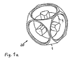
図1aは、従来技術による加速度センサのハウジングを示しており、ハウジングは、1つのパーツからフライス加工される。センサ要素を有しない3つのベース本体部20が、立方体形状のハウジング1内に示されており、それらのベース本体部も同様にフライス加工されたものである。
FIG. 1a shows a housing of an acceleration sensor according to the prior art, which is milled from one part. Three
各センサ要素2は、まず、ハウジング1内に完全に設置されるが、このことは、ハウジング1の内部が視認的に小さい場合には、困難であり且つ多くの時間を必要とする。この場合、ハウジングは、将来、さらに小さくなっていき、このために、フライス加工を行うことも益々困難になることが予測できる。
Each
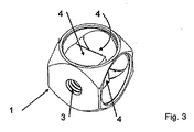
加速度センサを取り付けるための取り付け用ねじ孔3がハウジング1に外向きに配置されていることが、図4から理解され得る。その結果、センサ要素2を収容する支持体4は、取り付け用ねじ孔3の反対側にあり、拡大させることができない。この領域の壁の厚さは、結果的にかなり小さくなり、それは、問題である。したがって、壁の厚さがねじ孔にとって小さ過ぎるので、センサ要素2を、ハウジング1内にねじ込むことができない。
It can be seen from FIG. 4 that the
しかしながら、内部支持体4は、外部構成と比較して、小さいサイズのハウジング1、及びセンサ要素2、計測用電子機器及び配線の保護構成を可能にする。
However, the
本発明により、加速度センサのハウジング1はチタン又はアルミニウム材料から成る。
According to the invention, the
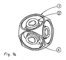
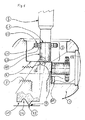
センサ要素2(図2)自体は、好適には、高い剛性を確保するように、チタン又は鋼から成るベース本体部20を含む。ベース本体部20は、好適には円形又は多角形の頭部21を備えており、頭部21は、振動質量体22により包囲されており、振動質量体22は、好適にはシュリンク・リングの形状のクランプ・リング27によりさらに包囲されている。クランプ・リング27及び振動質量体22は、組み合わされた性質を備えて一体に構成され得る。1つ又は複数の圧電要素23は、振動質量体22と頭部21との間の円弧状の窪み内に配置される。ベース本体部20の端面24は、支持体4上に位置付けられることとなり、頭部21から離れる方向を向いており、好適には、環状隆起部25を備え、環状隆起部25は、溝26によって外側を取り囲まれている。外側に配置された溝26は、溶解物を完全に収容するためのより大容量を可能にし、ゆえに、小さい直径のベース本体部20のための品質的に良好な接続を可能にする。
The sensor element 2 (FIG. 2) itself preferably comprises a
センサ要素2は、ピン形状の様式に構成され得る。端面24を横断する軸を有する上述のタイプのセンサ要素2は、端面24と、各圧電要素23、振動質量体22、さらにクランプ・リング27との間に軸方向空間を有しており、本発明の意味において、ピンとして有効である。各々の場合に、この軸は、計測されることとなる複数のセンサ軸の1つに一致する。
The
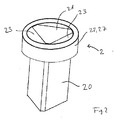
ハウジング1内に予め設置されるセンサ要素2を設置するためには、上述のように、センサ要素2の端面24は、支持体4(図4)の接合面6に対して平行に位置付けられ、隆起部25の先端のみが、接合面6に接触し、プロセスにおいて、導電性接触ゾーン7を構成する。
In order to install the
続いて、溶接電極5が、規定の力で導電的に頭部21に適用され、溶接電極5は、抵抗溶接用システム(図示せず)に接続される。規定の溶接電圧を印加することにより、電流が発生して、溶接電極5と、頭部21を有するベース本体部20と、ハウジング1と、さらに対抗電極とを流れ、このことは、隆起部25、及び接触ゾーン7内の接合面6の対応する領域の少なくとも部分的溶解をもたらし、ゆえに、少なくとも1つの環状の物質的に結合した接続が形成されるようになっている。いずれの過剰な溶解物も、溝26に流れ込み得る。その結果、正確で及び平面的に配向された接続が得られ、それは、迅速に形成され得、さらなる領域削減も可能にする。
Subsequently, the
抵抗溶接に代えて、この接続は、摩擦溶接、誘導加熱ろう付け、又はレーザ溶接によっても形成され得る。 Instead of resistance welding, this connection can also be formed by friction welding, induction heat brazing, or laser welding.
支持部4又はハウジング1の周囲領域は、一般に、溶接によって損なわれない。
The
同様に、三軸において加速度を計測する加速度センサの場合、他の2つのセンサ要素2がハウジング1内に配置され、ハウジング1は、それに応じて、新たに装置内に固定される。
Similarly, in the case of an acceleration sensor that measures acceleration in three axes, the other two
計測電子機器28はまた、支持体4又は頭部21に配置され得る。センサ要素2を導入した後、これらのセンサ要素は、計測電子機器28と、さらにプラグ(図示せず)と電気配線される。プラグは、センサ要素2及び支持体4を覆う蓋29に備えられる。
The
支持体4を有する本発明による加速度センサのハウジング1は、好適には、チタン又はアルミニウム材料から成り、一方、センサ要素2のベース本体部20は、好適には、チタン又は鋼から成る。
The
プラグのための結線はプラグ開口を介して取り出され、蓋29は、好適には、続いてクリック止めされ、結線はプラグに接続され、最終的には、プラグは蓋開口に接合される。 The connection for the plug is taken out through the plug opening and the lid 29 is preferably subsequently clicked, the connection is connected to the plug, and finally the plug is joined to the lid opening.
1 ハウジング
2 センサ要素
3 取り付け用ねじ孔
4 支持体
5 溶接電極
6 接合面
7 接触ゾーン
20 ベース本体部
21 頭部
22 振動質量体
23 圧電計測要素
24 端面
25 隆起部
26 溝
27 クランプ・リング
28 計測電子機器
29 蓋
DESCRIPTION OF
Claims (13)
a)ベース本体部(20)の頭部(21)を少なくとも1つの圧電計測要素(23)により包囲し、振動質量体(22)及びクランプ・リング(27)により包囲することにより、センサ要素(2)を予め設置するステップ、
b)前記予め設置されたセンサ要素(2)の前記ベース本体部(20)の端面(24)を位置決めするステップであって、前記端面は、前記頭部(21)の反対側にあり、前記端面(24)と支持体(4)との間に接触ゾーン(7)を形成するように前記ハウジング(1)の前記支持体(4)と接触する、ステップ、
c)接触ゾーン(7)において物質的に結合された接続を構成するように、前記ハウジング(1)の前記支持体(4)に前記予め設置されたセンサ要素(2)の前記端面(24)を溶接するステップ
を特徴とする、方法。 A method of manufacturing an acceleration sensor used in a machine, system, vehicle, or airplane, wherein the completed acceleration sensor includes a housing (1) whose basic shape is a cylinder or a cube, and the housing (1) In the method, comprising at least one internal support (4), on which a sensor element (2) is arranged, the method steps:
a) The sensor element (21) by surrounding the head (21) of the base body (20) with at least one piezoelectric measuring element (23) and with the vibrating mass (22) and the clamp ring (27). 2) pre-installing step,
b) positioning the end surface (24) of the base body (20) of the pre-installed sensor element (2), the end surface being on the opposite side of the head (21), Contacting the support (4) of the housing (1) to form a contact zone (7) between the end face (24) and the support (4);
c) the end face (24) of the pre-installed sensor element (2) on the support (4) of the housing (1) so as to constitute a materially coupled connection in the contact zone (7) A method characterized by welding.
Applications Claiming Priority (5)
| Application Number | Priority Date | Filing Date | Title |
|---|---|---|---|
| CH411/13 | 2013-02-07 | ||
| CH00411/13A CH707602A2 (en) | 2013-02-07 | 2013-02-07 | Producing sensor used for measuring values of acceleration in e.g. axles, by premounting sensor element by surrounding head part with piezoelectric measuring element, seismic composition and clamping ring, and welding element to housing |
| CH594/13 | 2013-03-13 | ||
| CH00594/13A CH707704A1 (en) | 2013-03-13 | 2013-03-13 | A method of manufacturing an acceleration sensor. |
| PCT/CH2014/000015 WO2014121407A1 (en) | 2013-02-07 | 2014-02-06 | Method for producing an acceleration sensor |
Publications (2)
| Publication Number | Publication Date |
|---|---|
| JP2016509678A JP2016509678A (en) | 2016-03-31 |
| JP6232077B2 true JP6232077B2 (en) | 2017-11-15 |
Family
ID=50150512
Family Applications (1)
| Application Number | Title | Priority Date | Filing Date |
|---|---|---|---|
| JP2015556356A Active JP6232077B2 (en) | 2013-02-07 | 2014-02-06 | Method for manufacturing acceleration sensor |
Country Status (7)
| Country | Link |
|---|---|
| US (1) | US9841434B2 (en) |
| EP (1) | EP2954333B1 (en) |
| JP (1) | JP6232077B2 (en) |
| CN (1) | CN104969078B (en) |
| DK (1) | DK2954333T3 (en) |
| ES (1) | ES2617976T3 (en) |
| WO (1) | WO2014121407A1 (en) |
Families Citing this family (5)
| Publication number | Priority date | Publication date | Assignee | Title |
|---|---|---|---|---|
| US10274627B2 (en) | 2015-10-30 | 2019-04-30 | Ion Geophysical Corporation | Ocean bottom seismic systems |
| CN108291926B (en) | 2015-12-04 | 2020-08-07 | 基斯特勒控股公司 | Accelerometer and method of making the same |
| WO2017093100A1 (en) | 2015-12-04 | 2017-06-08 | Kistler Holding Ag | Acceleration measuring device and method for the production of an acceleration measuring device of said type |
| FR3050668B1 (en) | 2016-04-29 | 2018-05-04 | Continental Automotive France | METHOD FOR WELDING A NICKEL RESISTANCE LEG WITH A BRONZE CONNECTION PIN AND A BRASS CONTACT RING IN AN ACCELEROMETER SENSOR |
| US11204365B2 (en) | 2018-09-13 | 2021-12-21 | Ion Geophysical Corporation | Multi-axis, single mass accelerometer |
Family Cites Families (24)
| Publication number | Priority date | Publication date | Assignee | Title |
|---|---|---|---|---|
| US3093759A (en) * | 1958-10-22 | 1963-06-11 | Gulton Ind Inc | Accelerometer |
| US3307054A (en) * | 1959-09-15 | 1967-02-28 | Endevco Corp | Accelerometer |
| GB1393312A (en) * | 1972-11-27 | 1975-05-07 | Becton Dickinson Co | Transducdr |
| FR2448721A1 (en) * | 1979-02-09 | 1980-09-05 | Cartier Jean | PIEZOELECTRIC ACCELEROMETER |
| US4771637A (en) * | 1987-03-18 | 1988-09-20 | Kistler Instrument Corporation | Accelerometer |
| US4815547A (en) * | 1987-11-30 | 1989-03-28 | Toledo Scale Corporation | Load cell |
| US5224380A (en) | 1990-05-21 | 1993-07-06 | The University Of Maryland | Superconducting six-axis accelerometer |
| US5124938A (en) * | 1990-07-23 | 1992-06-23 | Recon/Optical, Inc. | Gyroless platform stabilization techniques |
| JPH05172842A (en) * | 1991-11-18 | 1993-07-13 | Hitachi Ltd | Multiaxial detection type acceleration sensor |
| US5540808A (en) * | 1993-02-24 | 1996-07-30 | Deka Products Limited Partnership | Energy director for ultrasonic welding and joint produced thereby |
| US5677487A (en) * | 1995-10-13 | 1997-10-14 | A/S Bruel & Kjaer | Method and apparatus for measuring acceleration or mechanical forces |
| JPH1032276A (en) * | 1996-07-16 | 1998-02-03 | Nec Corp | Packaging method for power semiconductor device |
| US6279395B1 (en) * | 1999-02-05 | 2001-08-28 | Kistler Instrument Corporation | Annual shear element with radial preload |
| US7178399B2 (en) * | 2004-03-03 | 2007-02-20 | Innalabs Technologies, Inc. | Housing for magnetofluidic accelerometer |
| IL137572A0 (en) * | 2000-07-28 | 2003-06-24 | Israel Aircraft Ind Ltd | Compact inertial measurement unit |
| JP3730130B2 (en) * | 2001-02-20 | 2005-12-21 | オリジン電気株式会社 | Resistance welding equipment |
| JP2003078057A (en) * | 2001-08-31 | 2003-03-14 | Nippon Telegr & Teleph Corp <Ntt> | Semiconductor element mounting package |
| JP4187066B2 (en) * | 2003-01-27 | 2008-11-26 | 株式会社村田製作所 | Resistance welding method, apparatus, and electronic component manufacturing method |
| EP1443331A3 (en) * | 2003-02-03 | 2005-10-12 | Denso Corporation | Sensor device and ceramic package for mounting electronic components |
| US7482193B2 (en) * | 2004-12-20 | 2009-01-27 | Honeywell International Inc. | Injection-molded package for MEMS inertial sensor |
| JP2007218288A (en) * | 2006-02-14 | 2007-08-30 | Honda Motor Co Ltd | Weld nut |
| JP2007229719A (en) * | 2006-02-27 | 2007-09-13 | Hitachi Ltd | Pipe end sealing method |
| JP2008016867A (en) * | 2007-09-21 | 2008-01-24 | Toyota Motor Corp | Resistance welding method and resistance welding equipment |
| CN102121829B (en) * | 2010-08-09 | 2013-06-12 | 汪滔 | Miniature inertia measurement system |
-
2014
- 2014-02-06 ES ES14705469.6T patent/ES2617976T3/en active Active
- 2014-02-06 EP EP14705469.6A patent/EP2954333B1/en active Active
- 2014-02-06 CN CN201480007853.6A patent/CN104969078B/en active Active
- 2014-02-06 JP JP2015556356A patent/JP6232077B2/en active Active
- 2014-02-06 US US14/766,566 patent/US9841434B2/en active Active
- 2014-02-06 WO PCT/CH2014/000015 patent/WO2014121407A1/en not_active Ceased
- 2014-02-06 DK DK14705469.6T patent/DK2954333T3/en active
Also Published As
| Publication number | Publication date |
|---|---|
| CN104969078A (en) | 2015-10-07 |
| JP2016509678A (en) | 2016-03-31 |
| CN104969078B (en) | 2018-04-10 |
| EP2954333A1 (en) | 2015-12-16 |
| EP2954333B1 (en) | 2017-01-11 |
| ES2617976T3 (en) | 2017-06-20 |
| US20160003864A1 (en) | 2016-01-07 |
| WO2014121407A1 (en) | 2014-08-14 |
| DK2954333T3 (en) | 2017-03-20 |
| US9841434B2 (en) | 2017-12-12 |
Similar Documents
| Publication | Publication Date | Title |
|---|---|---|
| JP6232077B2 (en) | Method for manufacturing acceleration sensor | |
| EP3556872B1 (en) | Temperature sensor | |
| JP6476180B2 (en) | Piezoelectric power sensor having an electrical connection between an electrode and a contact pin | |
| JP2016099338A (en) | Integrated IBS device with clamp and cable connection | |
| JP5833936B2 (en) | Pressure sensor | |
| JP5761113B2 (en) | Pressure detecting device and production method thereof | |
| JP6924106B2 (en) | Fluid property detector | |
| JP6571873B2 (en) | Acceleration measuring apparatus and method for manufacturing the acceleration measuring apparatus | |
| WO2018055865A1 (en) | Force sensor | |
| CN104121934A (en) | Sensor unit | |
| JP6171251B2 (en) | Pressure detection device | |
| US7895897B2 (en) | Sensor assembly and use of a sensor assembly | |
| CN104220881B (en) | The battery sensor of electronics | |
| JP2017007307A (en) | Method for producing resin molding-fitted cable | |
| JP6709486B2 (en) | Pressure sensor | |
| JP2006284151A (en) | Igniter assembly | |
| KR101606151B1 (en) | A sensor assembly | |
| US20180219311A1 (en) | Surface Mount Contact, Electronic Device Assembly, and Test Probe Pin Tool | |
| CN105651414A (en) | Temperature sensor with enhanced tensile strength | |
| JP6539415B2 (en) | Acceleration measuring device and method for manufacturing acceleration measuring device | |
| JP2012181127A (en) | Pressure sensor | |
| JP2017217868A (en) | Synthetic resin molding and method for producing the same | |
| JP2021108333A (en) | Lamination core, current detector, and joint method | |
| JP6817058B2 (en) | Manufacturing method of pressure detector and pressure detector | |
| CN120403955A (en) | Pressure sensing probe and installation method |
Legal Events
| Date | Code | Title | Description |
|---|---|---|---|
| A521 | Request for written amendment filed |
Free format text: JAPANESE INTERMEDIATE CODE: A523 Effective date: 20161121 |
|
| A621 | Written request for application examination |
Free format text: JAPANESE INTERMEDIATE CODE: A621 Effective date: 20170130 |
|
| A977 | Report on retrieval |
Free format text: JAPANESE INTERMEDIATE CODE: A971007 Effective date: 20171003 |
|
| TRDD | Decision of grant or rejection written | ||
| A01 | Written decision to grant a patent or to grant a registration (utility model) |
Free format text: JAPANESE INTERMEDIATE CODE: A01 Effective date: 20171011 |
|
| A61 | First payment of annual fees (during grant procedure) |
Free format text: JAPANESE INTERMEDIATE CODE: A61 Effective date: 20171020 |
|
| R150 | Certificate of patent or registration of utility model |
Ref document number: 6232077 Country of ref document: JP Free format text: JAPANESE INTERMEDIATE CODE: R150 |
|
| R250 | Receipt of annual fees |
Free format text: JAPANESE INTERMEDIATE CODE: R250 |
|
| R250 | Receipt of annual fees |
Free format text: JAPANESE INTERMEDIATE CODE: R250 |
|
| R250 | Receipt of annual fees |
Free format text: JAPANESE INTERMEDIATE CODE: R250 |
|
| R250 | Receipt of annual fees |
Free format text: JAPANESE INTERMEDIATE CODE: R250 |
|
| R250 | Receipt of annual fees |
Free format text: JAPANESE INTERMEDIATE CODE: R250 |
|
| R250 | Receipt of annual fees |
Free format text: JAPANESE INTERMEDIATE CODE: R250 |