EP3385181A1 - Récipient séparable à stratification - Google Patents
Récipient séparable à stratification Download PDFInfo
- Publication number
- EP3385181A1 EP3385181A1 EP16870815.4A EP16870815A EP3385181A1 EP 3385181 A1 EP3385181 A1 EP 3385181A1 EP 16870815 A EP16870815 A EP 16870815A EP 3385181 A1 EP3385181 A1 EP 3385181A1
- Authority
- EP
- European Patent Office
- Prior art keywords
- mouth
- cap
- container
- fresh air
- air inlet
- Prior art date
- Legal status (The legal status is an assumption and is not a legal conclusion. Google has not performed a legal analysis and makes no representation as to the accuracy of the status listed.)
- Granted
Links
- 238000003475 lamination Methods 0.000 title 1
- 238000003860 storage Methods 0.000 claims abstract description 46
- 230000007423 decrease Effects 0.000 claims abstract description 13
- 238000007789 sealing Methods 0.000 claims description 37
- 238000000034 method Methods 0.000 claims description 12
- -1 polypropylene Polymers 0.000 claims description 10
- 239000004743 Polypropylene Substances 0.000 claims description 8
- 229920001155 polypropylene Polymers 0.000 claims description 8
- XAGFODPZIPBFFR-UHFFFAOYSA-N aluminium Chemical compound [Al] XAGFODPZIPBFFR-UHFFFAOYSA-N 0.000 claims description 5
- 229910052782 aluminium Inorganic materials 0.000 claims description 5
- 238000000071 blow moulding Methods 0.000 claims description 4
- 230000000149 penetrating effect Effects 0.000 claims description 4
- 230000002401 inhibitory effect Effects 0.000 abstract description 4
- 239000010410 layer Substances 0.000 description 75
- 229920000219 Ethylene vinyl alcohol Polymers 0.000 description 10
- 239000004715 ethylene vinyl alcohol Substances 0.000 description 9
- 238000003825 pressing Methods 0.000 description 7
- 238000005520 cutting process Methods 0.000 description 6
- 238000004519 manufacturing process Methods 0.000 description 6
- 230000004888 barrier function Effects 0.000 description 5
- 230000032798 delamination Effects 0.000 description 5
- 239000003566 sealing material Substances 0.000 description 5
- 239000002344 surface layer Substances 0.000 description 5
- VGGSQFUCUMXWEO-UHFFFAOYSA-N Ethene Chemical compound C=C VGGSQFUCUMXWEO-UHFFFAOYSA-N 0.000 description 4
- 239000005977 Ethylene Substances 0.000 description 4
- 230000000052 comparative effect Effects 0.000 description 4
- 229920000092 linear low density polyethylene Polymers 0.000 description 4
- 239000004707 linear low-density polyethylene Substances 0.000 description 4
- 229920001684 low density polyethylene Polymers 0.000 description 4
- 239000004702 low-density polyethylene Substances 0.000 description 4
- QVGXLLKOCUKJST-UHFFFAOYSA-N atomic oxygen Chemical compound [O] QVGXLLKOCUKJST-UHFFFAOYSA-N 0.000 description 3
- 230000008901 benefit Effects 0.000 description 3
- 230000015556 catabolic process Effects 0.000 description 3
- 230000006835 compression Effects 0.000 description 3
- 238000007906 compression Methods 0.000 description 3
- 229920001577 copolymer Polymers 0.000 description 3
- 238000006731 degradation reaction Methods 0.000 description 3
- 239000012634 fragment Substances 0.000 description 3
- 239000000203 mixture Substances 0.000 description 3
- 238000000465 moulding Methods 0.000 description 3
- 239000001301 oxygen Substances 0.000 description 3
- 229910052760 oxygen Inorganic materials 0.000 description 3
- 229920000098 polyolefin Polymers 0.000 description 3
- 229920006300 shrink film Polymers 0.000 description 3
- 239000004698 Polyethylene Substances 0.000 description 2
- 239000002253 acid Substances 0.000 description 2
- 230000008878 coupling Effects 0.000 description 2
- 238000010168 coupling process Methods 0.000 description 2
- 238000005859 coupling reaction Methods 0.000 description 2
- 230000007547 defect Effects 0.000 description 2
- 239000005038 ethylene vinyl acetate Substances 0.000 description 2
- 239000007789 gas Substances 0.000 description 2
- 229920001903 high density polyethylene Polymers 0.000 description 2
- 239000004700 high-density polyethylene Substances 0.000 description 2
- 239000000463 material Substances 0.000 description 2
- 229920001200 poly(ethylene-vinyl acetate) Polymers 0.000 description 2
- 229920000573 polyethylene Polymers 0.000 description 2
- 229920005989 resin Polymers 0.000 description 2
- 239000011347 resin Substances 0.000 description 2
- 238000000926 separation method Methods 0.000 description 2
- 238000002834 transmittance Methods 0.000 description 2
- XTXRWKRVRITETP-UHFFFAOYSA-N Vinyl acetate Chemical compound CC(=O)OC=C XTXRWKRVRITETP-UHFFFAOYSA-N 0.000 description 1
- 238000007664 blowing Methods 0.000 description 1
- 125000003178 carboxy group Chemical group [H]OC(*)=O 0.000 description 1
- 238000010586 diagram Methods 0.000 description 1
- 230000007062 hydrolysis Effects 0.000 description 1
- 238000006460 hydrolysis reaction Methods 0.000 description 1
- 230000005764 inhibitory process Effects 0.000 description 1
- FPYJFEHAWHCUMM-UHFFFAOYSA-N maleic anhydride Chemical compound O=C1OC(=O)C=C1 FPYJFEHAWHCUMM-UHFFFAOYSA-N 0.000 description 1
- 238000001094 photothermal spectroscopy Methods 0.000 description 1
- 238000002360 preparation method Methods 0.000 description 1
- 238000004064 recycling Methods 0.000 description 1
- 230000009467 reduction Effects 0.000 description 1
- 230000001629 suppression Effects 0.000 description 1
- XLYOFNOQVPJJNP-UHFFFAOYSA-N water Chemical compound O XLYOFNOQVPJJNP-UHFFFAOYSA-N 0.000 description 1
- 238000003466 welding Methods 0.000 description 1
Images


Classifications
-
- B—PERFORMING OPERATIONS; TRANSPORTING
- B65—CONVEYING; PACKING; STORING; HANDLING THIN OR FILAMENTARY MATERIAL
- B65D—CONTAINERS FOR STORAGE OR TRANSPORT OF ARTICLES OR MATERIALS, e.g. BAGS, BARRELS, BOTTLES, BOXES, CANS, CARTONS, CRATES, DRUMS, JARS, TANKS, HOPPERS, FORWARDING CONTAINERS; ACCESSORIES, CLOSURES, OR FITTINGS THEREFOR; PACKAGING ELEMENTS; PACKAGES
- B65D1/00—Rigid or semi-rigid containers having bodies formed in one piece, e.g. by casting metallic material, by moulding plastics, by blowing vitreous material, by throwing ceramic material, by moulding pulped fibrous material or by deep-drawing operations performed on sheet material
- B65D1/02—Bottles or similar containers with necks or like restricted apertures, designed for pouring contents
- B65D1/0223—Bottles or similar containers with necks or like restricted apertures, designed for pouring contents characterised by shape
- B65D1/023—Neck construction
- B65D1/0238—Integral frangible closures
-
- B—PERFORMING OPERATIONS; TRANSPORTING
- B65—CONVEYING; PACKING; STORING; HANDLING THIN OR FILAMENTARY MATERIAL
- B65D—CONTAINERS FOR STORAGE OR TRANSPORT OF ARTICLES OR MATERIALS, e.g. BAGS, BARRELS, BOTTLES, BOXES, CANS, CARTONS, CRATES, DRUMS, JARS, TANKS, HOPPERS, FORWARDING CONTAINERS; ACCESSORIES, CLOSURES, OR FITTINGS THEREFOR; PACKAGING ELEMENTS; PACKAGES
- B65D1/00—Rigid or semi-rigid containers having bodies formed in one piece, e.g. by casting metallic material, by moulding plastics, by blowing vitreous material, by throwing ceramic material, by moulding pulped fibrous material or by deep-drawing operations performed on sheet material
- B65D1/02—Bottles or similar containers with necks or like restricted apertures, designed for pouring contents
- B65D1/0223—Bottles or similar containers with necks or like restricted apertures, designed for pouring contents characterised by shape
- B65D1/023—Neck construction
- B65D1/0246—Closure retaining means, e.g. beads, screw-threads
-
- B—PERFORMING OPERATIONS; TRANSPORTING
- B65—CONVEYING; PACKING; STORING; HANDLING THIN OR FILAMENTARY MATERIAL
- B65D—CONTAINERS FOR STORAGE OR TRANSPORT OF ARTICLES OR MATERIALS, e.g. BAGS, BARRELS, BOTTLES, BOXES, CANS, CARTONS, CRATES, DRUMS, JARS, TANKS, HOPPERS, FORWARDING CONTAINERS; ACCESSORIES, CLOSURES, OR FITTINGS THEREFOR; PACKAGING ELEMENTS; PACKAGES
- B65D1/00—Rigid or semi-rigid containers having bodies formed in one piece, e.g. by casting metallic material, by moulding plastics, by blowing vitreous material, by throwing ceramic material, by moulding pulped fibrous material or by deep-drawing operations performed on sheet material
- B65D1/32—Containers adapted to be temporarily deformed by external pressure to expel contents
-
- B—PERFORMING OPERATIONS; TRANSPORTING
- B65—CONVEYING; PACKING; STORING; HANDLING THIN OR FILAMENTARY MATERIAL
- B65D—CONTAINERS FOR STORAGE OR TRANSPORT OF ARTICLES OR MATERIALS, e.g. BAGS, BARRELS, BOTTLES, BOXES, CANS, CARTONS, CRATES, DRUMS, JARS, TANKS, HOPPERS, FORWARDING CONTAINERS; ACCESSORIES, CLOSURES, OR FITTINGS THEREFOR; PACKAGING ELEMENTS; PACKAGES
- B65D41/00—Caps, e.g. crown caps or crown seals, i.e. members having parts arranged for engagement with the external periphery of a neck or wall defining a pouring opening or discharge aperture; Protective cap-like covers for closure members, e.g. decorative covers of metal foil or paper
- B65D41/02—Caps or cap-like covers without lines of weakness, tearing strips, tags, or like opening or removal devices
- B65D41/16—Snap-on caps or cap-like covers
- B65D41/18—Snap-on caps or cap-like covers non-metallic, e.g. made of paper or plastics
- B65D41/185—Snap-on caps or cap-like covers non-metallic, e.g. made of paper or plastics with integral internal sealing means
-
- B—PERFORMING OPERATIONS; TRANSPORTING
- B65—CONVEYING; PACKING; STORING; HANDLING THIN OR FILAMENTARY MATERIAL
- B65D—CONTAINERS FOR STORAGE OR TRANSPORT OF ARTICLES OR MATERIALS, e.g. BAGS, BARRELS, BOTTLES, BOXES, CANS, CARTONS, CRATES, DRUMS, JARS, TANKS, HOPPERS, FORWARDING CONTAINERS; ACCESSORIES, CLOSURES, OR FITTINGS THEREFOR; PACKAGING ELEMENTS; PACKAGES
- B65D51/00—Closures not otherwise provided for
- B65D51/18—Arrangements of closures with protective outer cap-like covers or of two or more co-operating closures
- B65D51/20—Caps, lids, or covers co-operating with an inner closure arranged to be opened by piercing, cutting, or tearing
- B65D51/22—Caps, lids, or covers co-operating with an inner closure arranged to be opened by piercing, cutting, or tearing having means for piercing, cutting, or tearing the inner closure
- B65D51/221—Caps, lids, or covers co-operating with an inner closure arranged to be opened by piercing, cutting, or tearing having means for piercing, cutting, or tearing the inner closure a major part of the inner closure being left inside the container after the opening
- B65D51/222—Caps, lids, or covers co-operating with an inner closure arranged to be opened by piercing, cutting, or tearing having means for piercing, cutting, or tearing the inner closure a major part of the inner closure being left inside the container after the opening the piercing or cutting means being integral with, or fixedly attached to, the outer closure
-
- B—PERFORMING OPERATIONS; TRANSPORTING
- B65—CONVEYING; PACKING; STORING; HANDLING THIN OR FILAMENTARY MATERIAL
- B65D—CONTAINERS FOR STORAGE OR TRANSPORT OF ARTICLES OR MATERIALS, e.g. BAGS, BARRELS, BOTTLES, BOXES, CANS, CARTONS, CRATES, DRUMS, JARS, TANKS, HOPPERS, FORWARDING CONTAINERS; ACCESSORIES, CLOSURES, OR FITTINGS THEREFOR; PACKAGING ELEMENTS; PACKAGES
- B65D77/00—Packages formed by enclosing articles or materials in preformed containers, e.g. boxes, cartons, sacks or bags
- B65D77/04—Articles or materials enclosed in two or more containers disposed one within another
- B65D77/06—Liquids or semi-liquids or other materials or articles enclosed in flexible containers disposed within rigid containers
-
- B—PERFORMING OPERATIONS; TRANSPORTING
- B65—CONVEYING; PACKING; STORING; HANDLING THIN OR FILAMENTARY MATERIAL
- B65D—CONTAINERS FOR STORAGE OR TRANSPORT OF ARTICLES OR MATERIALS, e.g. BAGS, BARRELS, BOTTLES, BOXES, CANS, CARTONS, CRATES, DRUMS, JARS, TANKS, HOPPERS, FORWARDING CONTAINERS; ACCESSORIES, CLOSURES, OR FITTINGS THEREFOR; PACKAGING ELEMENTS; PACKAGES
- B65D77/00—Packages formed by enclosing articles or materials in preformed containers, e.g. boxes, cartons, sacks or bags
- B65D77/22—Details
- B65D77/225—Pressure relief-valves incorporated in a container wall, e.g. valves comprising at least one elastic element
-
- B—PERFORMING OPERATIONS; TRANSPORTING
- B65—CONVEYING; PACKING; STORING; HANDLING THIN OR FILAMENTARY MATERIAL
- B65D—CONTAINERS FOR STORAGE OR TRANSPORT OF ARTICLES OR MATERIALS, e.g. BAGS, BARRELS, BOTTLES, BOXES, CANS, CARTONS, CRATES, DRUMS, JARS, TANKS, HOPPERS, FORWARDING CONTAINERS; ACCESSORIES, CLOSURES, OR FITTINGS THEREFOR; PACKAGING ELEMENTS; PACKAGES
- B65D83/00—Containers or packages with special means for dispensing contents
- B65D83/771—Containers or packages with special means for dispensing contents for dispensing fluent contents by means of a flexible bag or a deformable membrane or diaphragm
-
- B—PERFORMING OPERATIONS; TRANSPORTING
- B65—CONVEYING; PACKING; STORING; HANDLING THIN OR FILAMENTARY MATERIAL
- B65D—CONTAINERS FOR STORAGE OR TRANSPORT OF ARTICLES OR MATERIALS, e.g. BAGS, BARRELS, BOTTLES, BOXES, CANS, CARTONS, CRATES, DRUMS, JARS, TANKS, HOPPERS, FORWARDING CONTAINERS; ACCESSORIES, CLOSURES, OR FITTINGS THEREFOR; PACKAGING ELEMENTS; PACKAGES
- B65D1/00—Rigid or semi-rigid containers having bodies formed in one piece, e.g. by casting metallic material, by moulding plastics, by blowing vitreous material, by throwing ceramic material, by moulding pulped fibrous material or by deep-drawing operations performed on sheet material
- B65D1/02—Bottles or similar containers with necks or like restricted apertures, designed for pouring contents
- B65D1/0207—Bottles or similar containers with necks or like restricted apertures, designed for pouring contents characterised by material, e.g. composition, physical features
- B65D1/0215—Bottles or similar containers with necks or like restricted apertures, designed for pouring contents characterised by material, e.g. composition, physical features multilayered
-
- B—PERFORMING OPERATIONS; TRANSPORTING
- B65—CONVEYING; PACKING; STORING; HANDLING THIN OR FILAMENTARY MATERIAL
- B65D—CONTAINERS FOR STORAGE OR TRANSPORT OF ARTICLES OR MATERIALS, e.g. BAGS, BARRELS, BOTTLES, BOXES, CANS, CARTONS, CRATES, DRUMS, JARS, TANKS, HOPPERS, FORWARDING CONTAINERS; ACCESSORIES, CLOSURES, OR FITTINGS THEREFOR; PACKAGING ELEMENTS; PACKAGES
- B65D2251/00—Details relating to container closures
- B65D2251/0003—Two or more closures
- B65D2251/0006—Upper closure
- B65D2251/0025—Upper closure of the 47-type
-
- B—PERFORMING OPERATIONS; TRANSPORTING
- B65—CONVEYING; PACKING; STORING; HANDLING THIN OR FILAMENTARY MATERIAL
- B65D—CONTAINERS FOR STORAGE OR TRANSPORT OF ARTICLES OR MATERIALS, e.g. BAGS, BARRELS, BOTTLES, BOXES, CANS, CARTONS, CRATES, DRUMS, JARS, TANKS, HOPPERS, FORWARDING CONTAINERS; ACCESSORIES, CLOSURES, OR FITTINGS THEREFOR; PACKAGING ELEMENTS; PACKAGES
- B65D2251/00—Details relating to container closures
- B65D2251/0003—Two or more closures
- B65D2251/0068—Lower closure
- B65D2251/0093—Membrane
Definitions
- the present invention relates to a delaminatable container having an inner bag composed of an inner layer to be shrunk with a decrease in contents.
- delaminatable containers that inhibit entrance of air into the container using an inner bag composed of an inner layer to be shrunk with a decrease in contents (e.g., PTSs 1 to 5).
- Such a delaminatable container is generally used by mounting a cap having a check valve to a mouth of a container body.
- the delaminatable container in PTL 2 is configured to open and close a fresh air inlet by mounting a valve member to a fresh air inlet formed in an outer shell of a container body and moving the valve member relatively to the container body.
- the delaminatable container disclosed in PTL 3 has a cap mounted to a mouth of a container body having a built-in valve.
- the delaminatable container disclosed in PTL 4 has a valve provided inside a body of an outer shell.
- Such a delaminatable container has an advantage that the contents in the inner bag are not in contact with air.
- the container is also provided with a check valve in the cap not to flow the air back into the inner bag after pouring the contents.
- the container is further proposed to seal the mouth by an aluminum seal to secure tight closure during storage (e.g., refer to PTL 5).
- PTL 5 discloses a tube container in which a mouth of a tube body having non-transmittance of oxygen and an elastic restoring force is closed by a sealing material having non-transmittance of oxygen, a plug tube having a pouring hole is removably mounted to the mouth, the pouring hole in the plug tube is opened and closed by a valve that is closed by a negative pressure in the tube body, and the cap is fit to the plug tube to remove the sealing material and unseal the mouth.
- the present inventors tested container bodies of a delaminatable container with a press-fit cap mounted to the body and found that fresh air sometimes entered into the container body through a gap between the container body and the cap. Since entrance of fresh air into the container body promotes content degradation, it is desired to inhibit entrance of fresh air into the container body.
- the first aspect of the present invention has been made in view of such circumstances and is to provide a delaminatable container capable of inhibiting entrance of fresh air into the container body.
- the valve member In the configuration in PTL 2, the valve member is pressed against the outer shell by the inner bag, sometimes causing interference with movement of the valve member. In the case of such interference with movement of the valve member, fresh air is not appropriately introduced at a timing to introduce fresh air into a space between the outer shell and the inner bag through the fresh air inlet after discharge of the contents, and as a result, restorability of the outer shell sometimes becomes worse.
- the second aspect of the present invention has been made in view of such circumstances and is to provide a delaminatable container capable of immediate introduction of fresh air into the space between the outer shell and the inner bag after discharge of the contents.
- closure by a sealing material as described in PTL 5 is effective for security of storage life
- unsealing by a cutting blade in a tubular shape as described in PTL 5 may cause a risk of various troubles.
- fragments of the sealing material may remain attached to the cutting blade after cutting to close the flow passage.
- it is difficult to maintain tight closure to maintain tight closure after unsealing, an outer circumferential surface of the cutting blade has to closely contact with an inner circumferential surface of the mouth, requiring high molding precision of the cutting blade and leading to an increase in costs.
- the third aspect of the present invention has been made in view of such circumstances and is to provide a delaminatable container capable of maintaining airtightness during storage, resolving troubles for unsealing, and maintaining tight closure even after unsealing.
- the first aspect of the present invention provides a delaminatable container, including: a container body; and a press-fit cap mounted to the container body, wherein the container body is configured to include a storage portion to store contents and a mouth having an opening to discharge the contents from the storage portion, the storage portion and the mouth having an outer layer and an inner layer, and having an inner bag composed of the inner layer to be shrunk with a decrease in the contents, the mouth includes a mouth-side engagement section provided along an outer circumferential surface of the mouth, the cap includes a cap-side engagement section provided along an inner circumferential surface of the cap, the mouth-side engagement section and the cap-side engagement section are configured to be engageable with each other while the cap is mounted to the mouth, and at least one of the cap and the mouth includes a tilt suppressor to suppress a tilt of the cap relative to the mouth by narrowing a gap between the mouth and the cap in a position more distant from the opening than the cap-side engagement section while the cap is mounted to the mouth.
- the container body is configured
- the present inventors conducted a research on the cause of entrance of fresh air and found the cause that, depending on the shape of a mouth of a container body and the shape of a press-fit cap, the cap is sometimes prone to tilt relative to the mouth and a tilt of the cap causes a gap between the cap and the mouth. Based on the findings, a tilt suppressor to suppress a tilt of the cap relative to the mouth is provided to allow inhibition of entrance of fresh air into the container body, and thus have come to complete the present invention.
- the tilt suppressor is a mouth-side protrusion provided on the outer circumference of the mouth.
- the container further includes a constriction section constricting inside the mouth provided on a storage portion side from the mouth-side engagement section, wherein the mouth-side protrusion is provided between an upper wall of the constriction section and the mouth-side engagement section.
- the tilt suppressor is a cap-side protrusion provided on the inner circumferential surface of the cap.
- the storage portion includes a fresh air inlet communicating an external space with an intermediate space between the outer layer and the inner layer.
- the second aspect of the present invention provides a delaminatable container including a container body having an outer shell and an inner bag, the inner bag to be shrunk with a decrease in contents, wherein the outer shell includes a fresh air inlet communicating with an external space of the of the container body, and the inner bag has a surface area in an area facing the fresh air inlet greater than an open area of the fresh air inlet.
- the inner bag of the delaminatable container of the present invention has a surface area in an area facing the fresh air inlet greater than an open area of the fresh air inlet formed in the outer shell.
- the inner bag includes a recess recessed towards inside the container body in an area facing the fresh air inlet.
- the recess includes a tube section having an approximately constant cross-sectional area towards inside the container body.
- the recess includes a curved surface recessed towards inside the container body.
- the container body includes a storage portion to store the contents and a mouth to discharge the contents from the storage portion, and the fresh air inlet is provided in the storage portion.
- a valve member is mounted to the fresh air inlet, and the valve member is configured to open and close the fresh air inlet by opening and closing a gap between an edge of the fresh air inlet and the valve member by movement of the valve member.
- the valve member includes a stem inserted into the fresh air inlet, a lid provided on an intermediate space side in the stem and having a cross-sectional area greater than that of the stem, and a locking portion provided on a side of the external space in the stem and preventing entrance of the valve member to the intermediate space.
- Another aspect of the present invention provides a method of producing a delaminatable container, including: producing a container body having an outer shell and an inner bag delaminatable from each other by blow molding a laminated parison in a molten state, the outer shell and the inner bag having a recess or a convexity; and forming a fresh air inlet in the outer shell in a region containing the recess or the convexity.
- a delaminatable container in the third aspect of the present invention includes an outer shell and an inner bag, the inner bag to delaminate from the outer shell and be shrunk with a decrease in contents, wherein a mouth is sealed by a sealing member and a cap having a check valve is mounted to the mouth, the cap has an inner plug with a protrusion formed protruding towards the sealing member, the protrusion has an end in a peak shape and is formed with a content flow passage from a midway position thereof penetrating to an outflow side of the inner plug, and, by screwing the cap in, the protrusion of the inner plug breaks through the sealing member for unsealing.
- the mouth is sealed by the sealing member to certainly secure tight closure during storage.
- the sealing member is unsealed by the protrusion having an end in a peak shape and formed with a content flow passage from a midway position thereof penetrating to an outflow side of the inner plug, thereby suppressing failures such as flow passage closure due to attachment of fragments.
- the present invention provides a delaminatable container capable of maintaining airtightness during storage, resolving troubles for unsealing, and maintaining tight closure even after unsealing.
- the sealing member is fixed with its surroundings put between the mouth and an inner cap, the inner cap having a hole formed in a position facing the protrusion, and when the cap is screwed in, a circumferential surface of the protrusion in the peak shape abuts on a periphery of the hole of the inner cap.
- the check valve opens and closes an opening on the outflow side of the content flow passage formed in the protrusion.
- the sealing member is a multilayered film having a polypropylene layer, an aluminum layer, and a polypropylene layer laminated in this order.
- Embodiments of the present invention are described below. Various characteristics in the embodiments described below may be combined with each other. Each characteristic is independently inventive.
- the first and second embodiments mainly relate to the first aspect of the present invention.
- the third to sixth embodiments mainly relate to the second aspect of the present invention.
- the seventh embodiment mainly relates to the third aspect of the present invention.
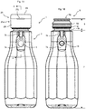
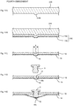
- a delaminatable container 1 in the first embodiment of the present invention includes a container body 2, a valve member 5, and a press-fit cap 23 mounted to the container body 2.
- the container body 2 is provided with a storage portion 7 to store the contents and a mouth 9 having an opening 9g to discharge the contents from the storage portion 7.
- the container body 2 includes an outer layer 17 and an inner layer 13 in the storage portion 7 and the mouth 9, where the outer layer 17 constitutes an outer shell 19 and the inner layer 13 constitutes an inner bag 14. Due to separation of the inner layer 13 from the outer layer 17 with a decrease in the contents, the inner bag 14 separates from the outer shell 19 to be shrunk. Preliminary delamination is sometimes performed to delaminate the inner layer 13 from the outer layer 17 before storage of the contents in the storage portion 7. In this case, the inner layer 13 is contacted with the outer layer 17 by blowing air or storing the contents in the storage portion 7 after preliminary delamination. The inner layer 13 then separates from the outer layer 17 with a decrease in the contents. Meanwhile, when preliminary delamination is not performed, the inner layer 13 is delaminated from the outer layer 17 in discharge of the contents to separate from the outer layer 17.
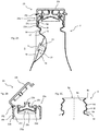
- the mouth 9 is provided with an engagement section 9d along an outer circumferential surface of the mouth 9.
- the mouth 9 is assumed to have a press-fit cap 23 mounted thereto, and the engagement section 9d is an annular projection engageable with an engagement section 23c of the cap 23.
- the mouth 9 also includes a constriction section 9c constricting inside the mouth 9 on the storage portion 7 side from the engagement section 9d.
- the constriction section 9c has an upper wall 9e extending approximately vertically to a central axis C of the mouth 9.
- the cap 23 to be mounted includes a cap body 23a and a cap cover 23i.
- the cap body 23a and the cap cover 23i are coupled in a coupling portion 23j to allow opening and closing of the cap cover 23i.
- the cap body 23a includes an upper portion 23t, an outlet 23b provided in the upper portion 23t, a tube section 23f cylindrically extending from the upper portion 23t, the engagement section 23c provided along an inner circumferential surface of the tube section 23f, an inner ring 23d cylindrically extending from the upper portion 23t inside the tube section 23f, a flow passage 23g provided inside the inner ring 23d and communicating with the outlet 23b, and a check valve 23e provided in the flow passage 23g.
- the engagement section 23c is an annular projection engageable with the engagement section 9d of the mouth 9. While the cap 23 is mounted to the mouth 9, the contents in the storage portion 7 are discharged from the outlet 23b through the flow passage 23g.
- the check valve 23e blocks an incoming flow of fresh air from the outlet 23b, and fresh air does not enter inside the inner bag 14 of the container body 2 to inhibit content degradation.
- the structure of the cap 23 described here is merely an example, and for example, a cap 23 having a check valve of another configuration may be employed.
- a support 10 is brought to abut on a lower surface of the upper wall 9e of the constriction section 9c.
- the engagement section 23c of the cap 23 is brought to abut on the engagement section 9d of the mouth 9.
- the cap 23 is further pressed, and as illustrated in Fig. 2A , the engagement section 23c passes over the engagement section 9d and thus the engagement section 23c is engaged with the engagement section 9d.
- the tube section 23f of the cap 23 transforms to enlarge the diameter and the mouth 9 transforms to reduce the diameter, and thus it is easier to mount the cap 23 when the mouth 9 readily transforms.
- the mouth 9 in the present embodiment is not provided with a support ring as disclosed in JP 11-292112A and the mouth 9 is supported by having the support 10 abutting on the lower surface of the upper wall 9e of the constriction section 9c. The mouth 9 thus readily transforms, and mounting of the cap 23 is facilitated.
- the inner bag 14 readily transform in the area near a container opening and it helps to use the contents up.
- the mouth 9 also includes an abutment section 9a on which an outer surface of the inner ring 23d abuts. Leakage of the contents and introduction of fresh air into the container body 2 are prevented by the outer surface of the inner ring 23d abutting on the abutment section 9a of the mouth 9.
- the mouth 9 is equipped with an enlarged diameter portion 9b at the end.
- the enlarged diameter portion 9b has an inner diameter greater than the inner diameter in an abutment section 9a, and thus the outer surface of the inner ring 23d is not in contact with the enlarged diameter portion 9b.
- the constriction section 9c is provided in a position closer to the storage portion 7 than the abutment section 9a to inhibit slipping off of the inner layer 13 by the constriction section 9c. Dropping of the inner bag 14 into the outer shell 19 is thus inhibited.
- the constriction section 9c thus has a function of inhibiting slipping off of the inner layer 13 and also has a function as a support area for the mouth 9 by the support 10 when the cap 23 is mounted.
- a protrusion 9f is provided in a position more distant from the opening 9g (position closer to the storage portion 7) than the engagement section 9d.
- the protrusion 9f is provided between the engagement section 9d and the upper wall 9e of the constriction section 9c.
- the protrusion 9f is formed by enlarging the diameter in the area between the engagement section 9d and the upper wall 9e of the constriction section 9c.
- the protrusion 9f functions as "the tilt suppressor" in the appended claims.
- the protrusion 9f may be, or does not have to be, in contact with the end 23h.
- the protrusion 9f and the end 23h in contact have an advantage of more effective suppression of the tilt of the cap 23.
- the protrusion 9f and the end 23h not in contact have an advantage of reduction in interference between the end 23h and the protrusion 9f when the cap 23 is mounted to the mouth 9.
- the storage portion 7 includes a valve member mounting recess 7a composed of an inclined plane, and the recess 7a includes a fresh air inlet 15.
- the fresh air inlet 15 is a through hole provided only in the outer shell 19 and communicates an intermediate space 21 between the outer shell 19 and the inner bag 14 with an external space S of the container body 2.
- the fresh air inlet 15 has the valve member 5 mounted thereto to regulate entrance and exit of air between the intermediate space 21 and the external space S.
- the recess 7a is provided to avoid interference between the valve member 5 and a shrink film when the storage portion 7 is covered with the shrink film.
- an air circulation groove 7b is provided that extends in the direction from the recess 7a to the mouth 9.
- the valve member 5 includes a stem 5a arranged in the fresh air inlet 15, a lid 5c provided on the intermediate space 21 side of the stem 5a and having a greater cross-sectional area than that of the stem 5a, and a locking portion 5b provided on the external space S side of the stem 5a and preventing entrance of the valve member 5 into the intermediate space 21.
- the lid 5c is inserted into the intermediate space 21 while pressing and expanding the fresh air inlet 15, thereby mounting the valve member 5 to the container body 2.
- the lid 5c preferably has an end in a tapered shape.
- Such a valve member 5 is mountable only by pressing the lid 5c into the intermediate space 21 from outside the container body 2 and is thus excellent in productivity.
- the lid 5c is configured to substantially close the fresh air inlet 15 when the outer shell 19 is compressed and has a shape of a smaller cross-sectional area as getting closer to the stem 5a.
- the locking portion 5b is configured to allow introduction of air into the intermediate space 21 when the outer shell 19 restores its shape after compression.
- the pressure in the intermediate space 21 becomes higher than the external pressure, leading to leakage of air in the intermediate space 21 from the fresh air inlet 15 to the outside.
- This pressure difference and the air flow cause movement of the lid 5c toward the fresh air inlet 15 to, as illustrated in Fig. 4B , close the fresh air inlet 15 with the lid 5c. Since the lid 5c has the shape with a smaller cross-sectional area as getting closer to the stem 5a, the lid 5c readily fits in the fresh air inlet 15 to close the fresh air inlet 15.
- the locking portion 5b includes a flow passage 5e to allow introduction of fresh air into the intermediate space 21 through the flow passage 5e and the fresh air inlet 15 even when the locking portion 5b abuts on the outer shell 19.
- the present embodiment is configured that the gap between an edge of the fresh air inlet 15 and the valve member 5 is opened and closed by the movement of the valve member 5 to allow the valve member 5 to open and close the fresh air inlet 15.
- the valve member itself may be configured to have a through hole and an on-off valve, which acts to open and close the through hole, thereby opening and closing the fresh air inlet 15.
- the container body 2 includes the outer layer 17 and the inner layer 13.
- the outer layer 17 is formed of, for example, low-density polyethylene, linear low-density polyethylene, high-density polyethylene, polypropylene, an ethylene-propylene copolymer, or a mixture thereof, or the like.
- the outer layer 17 may have a multilayer structure.
- the structure may be, for example, a configuration in which both sides of a repro layer are sandwiched by layers formed of a virgin material.
- the term "repro layer” refers to a layer formed by recycling burrs generated during container molding.
- the outer layer 17 is formed thicker than the inner layer 13 so as to increase the restorability thereof.
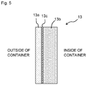
- the inner layer 13 includes an EVOH layer 13a provided on a container outer surface side, an inner surface layer 13b provided on a container inner surface side of the EVOH layer 13a, and an adhesion layer 13c provided between the EVOH layer 13a and the inner surface layer 13b.
- the adhesion layer 13c may be omitted.
- the EVOH layer 13a is a layer containing an ethylene-vinyl alcohol copolymer (EVOH) resin and is obtained by hydrolysis of a copolymer of ethylene and vinyl acetate.
- the EVOH resin has an ethylene content, for example, from 25 to 50 mol%, and from the perspective of oxygen barrier properties, it is preferably 32 mol% or less.
- the lower limit of the ethylene content is preferably 25 mol% or more because the flexibility of the EVOH layer 13a is prone to decrease when the ethylene content is less.
- the inner surface layer 13b is a layer in contact with the contents of the delaminatable container 1. It contains, for example, polyolefin, such as low-density polyethylene, linear low-density polyethylene, high-density polyethylene, polypropylene, an ethylene-propylene copolymer, and a mixture thereof, and preferably low-density polyethylene or linear low-density polyethylene.
- polyolefin such as low-density polyethylene, linear low-density polyethylene, high-density polyethylene, polypropylene, an ethylene-propylene copolymer, and a mixture thereof, and preferably low-density polyethylene or linear low-density polyethylene.
- the adhesion layer 13c is a layer having a function of adhering the outside layer 13a to the inner surface layer 13b, and it is, for example, a product of adding acid modified polyolefin (e.g., maleic anhydride modified polyethylene) with carboxyl groups introduced therein to polyolefin described above or an ethylene-vinyl acetate copolymer (EVA).
- acid modified polyolefin e.g., maleic anhydride modified polyethylene
- EVA ethylene-vinyl acetate copolymer
- An example of the adhesion layer 13c is a mixture of acid modified polyethylene with low-density polyethylene or linear low-density polyethylene.
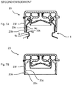
- the second embodiment of the present invention is described.
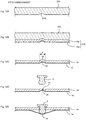
- the present embodiment is similar to the first embodiment and mainly differs in that a tilt suppressor is provided in a cap 23.
- the mouth 9 has no protrusion 9f.
- the configuration of the cap 23 is different from Comparative Example in Fig. 6 in that an end 23h includes a protrusion 23k.
- a gap G between the cap 23 and the mouth 9 at the end 23h is thus narrowed to suppress the tilt of the cap 23 relative to the mouth 9.
- the protrusion 23k functions as "the tilt suppressor" in the appended claims.
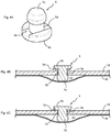
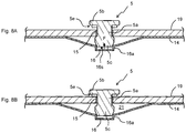
- the present embodiment is similar to the first embodiment and mainly differs in that a recess 16 is provided in the inner bag 14.
- the inner bag 14 is inflated by the contents to be in a state where the inner bag 14 is in contact with the lid 5c of the valve member 5.
- the compressive force is then released after the contents in the inner bag 14 are discharged by compressing the outer shell 19 and the inner bag 14, the outer shell 19 attempts to go away from the lid 5c to restore its original shape by the elasticity of its own. Since the inner bag 14 also attempts to restore its original shape by the elasticity of its own, a force in a direction of pressing the lid 5c against the outer shell 19 is applied to the lid 5c by the inner bag 14.
- the recess 16 recessing towards inside the container body 2 is provided in the inner bag 14 in the area facing the fresh air inlet 15 to have the surface area of the inner bag 14 in the area facing the fresh air inlet 15 greater than the open area of the fresh air inlet 15.
- a gap 16s is formed and the contact area between the valve member 5 and the inner bag 14 is reduced.
- Such configuration reduces the tension developed in the inner bag 14 when the inner bag 14 is pressed by the valve member 5 in the area where the valve member 5 is in contact with the inner bag 14.
- the force F in the direction of pressing the valve member 5 against the outer shell 19 by the inner bag 14 is thus less than that in the embodiment illustrated in 4B and 4C.
- a gap is readily formed between the outer shell 19 and the lid 5c after the first discharge of the contents, and fresh air is immediately introduced into the intermediate space 21 through the fresh air inlet 15 to immediately restore the original shape of the outer shell 19.
- the recess 16 in the present embodiment has a structure including a tube section 16a that has an approximately constant cross-sectional area towards inside the container body 2, the shape of the recess 16 is not particularly limited as long as the shape is capable of reducing the force F.
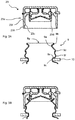
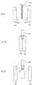
- a cylindrical laminated parison 232 in a molten state having a laminated structure corresponding to the container body 2 to be produced is extruded from an extruder 231, and while the laminated parison 232 is set between blow molding split dies 233 and 234, the split dies 233 and 234 are closed.
- the split dies 233 and 234 are provided with cavities 233a and 234a in a shape corresponding to the container body 2.
- a projection 233b is provided in a position intended to form the fresh air inlet 15.
- the laminated parison 232 includes a layer 19a to be the outer shell 19 and a layer 14a to be the inner bag 14.
- a blow nozzle 236 is inserted into an opening on the mouth 9 side of the container body 2 to blow air into the cavities 233a and 234a of the split dies 233 and 234 in the mold closing state for blow molding.
- the laminated parison 232 is pressed against inner surfaces of the cavities 233a and 234a.
- the layers 19a and 14a constituting the laminated parison 232 has a recess formed in a shape along the projection 233b.
- the outer shell 19 and the inner bag 14 of the container body 2 have recesses 18 and 16 formed in the shape along the projection 233b.
- the outer shell 19 in a region A containing the recess 18 is removed to form the fresh air inlet 15 in the outer shell 19.
- the recess 16 of the inner bag 14 is left as is. Since the projection 233b is in a columnar shape in the present embodiment, the tube section 16a having an approximately constant cross-sectional area towards inside the container body 2 is formed in the recess 16.
- the valve member 5 is mounted to the fresh air inlet 15 by inserting the valve member 5 into the fresh air inlet 15.
- the cap 23 is mounted to the mouth 9 to produce the delaminatable container 1 illustrated in Fig. 1A .
- the fourth embodiment of the present invention is described.
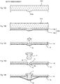
- the present embodiment is similar to the third embodiment and mainly differs in that the recess 16 includes a curved surface 16b.
- the following description is mainly given to the differences.
- Figs. 11A to 11E respectively correspond to Figs. 10A to 10E .
- the projection 233b has a curved surface.
- the layers 19a and 14a thus have a recess formed in a curved shape along the projection 233b, and as illustrated in Fig. 11C , the outer shell 19 and the inner bag 14 of the container body 2 have the recesses 18 and 16 formed in a curved shape.
- valve member 5 is mounted to the fresh air inlet 15 by inserting the valve member 5 into the fresh air inlet 15. Between the valve member 5 and the recess 16, the gap 16s is formed and the contact area between the valve member 5 and the inner bag 14 is reduced.
- the force F in the direction of pressing the valve member 5 against the outer shell 19 by the inner bag 14 is less than that in the embodiment illustrated in 4B and 4C.
- a gap is readily formed between the outer shell 19 and the lid 5c after the first discharge of the contents, and fresh air is immediately introduced into the intermediate space 21 through the fresh air inlet 15 to immediately restore the original shape of the outer shell 19.
- the fifth embodiment of the present invention is described.
- the present embodiment is similar to the fourth embodiment and mainly differs in that the split die 233 has a recess 233c in a curved shape.
- the following description is mainly given to the differences.
- Figs. 12A to12E respectively correspond to Figs. 11A to 11E .
- the split die 233 has the recess 233c in a curved shape.
- the layers 19a and 14a thus have a convexity formed in a curved shape along the recess 233c, and as illustrated in Fig. 12C , the outer shell 19 and the inner bag 14 of the container body 2 have convexities 22 and 20 formed in a curved shape.
- valve member 5 is mounted to the fresh air inlet 15 by inserting the valve member 5 into the fresh air inlet 15. At this point, the convexity 20 is pressed by the valve member 5 to become the recess 16 and the shape illustrated in Fig. 12E is obtained.
- the sixth embodiment of the present invention is described.
- the present embodiment is similar to the fourth embodiment and mainly differs in that the region A above is a region containing the entire recess 18, whereas the region A in the present embodiment is a region containing a portion of the recess 18.
- the following description is mainly given to the differences.
- Figs. 13A to 13E respectively correspond to Figs. 11A to 11E .
- the projection 233b is formed over a region wider than that of the fourth embodiment.
- the layers 19a and 14a thus have a recess is formed over a wide region along the projection 233b, and as illustrated in Fig. 13C , the outer shell 19 and the inner bag 14 of the container body 2 have the recesses 18 and 16 formed over a wide region.
- valve member 5 is mounted to the fresh air inlet 15 by inserting the valve member 5 into the fresh air inlet 15. Between the valve member 5 and the recess 16, a gap is formed and the contact area between the valve member 5 and the inner bag 14 is reduced.
- the force F in the direction of pressing the valve member 5 against the outer shell 19 by the inner bag 14 is less than that in the embodiment illustrated in 4B and 4C.
- a gap is readily formed between the outer shell 19 and the lid 5c after the first discharge of the contents, and fresh air is immediately introduced into the intermediate space 21 through the fresh air inlet 15 to immediately restore the original shape of the outer shell 19.
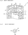
- the container body 2 is the main subject of the delaminatable container 1 in the present embodiment, and the container body 2 includes a storage portion 3 to store the contents and a mouth 4 to discharge the contents from the storage portion 3.
- the recess 7a, the air circulation groove 7b, and the valve member 5 are as described in the first embodiment.
- the mouth 4 is provided with an external screw portion, and to the external screw portion, a cap 30 having an internal screw is mounted. A detailed description is given below to the configuration of a mounting portion of the cap 30.
- the cap 30 is mounted to the mouth 4 of the container body 2, and as illustrated in Fig. 15 , composed of inner cap 31 directly fixed to the mouth 4 of the container body 2, screwed to an external screw portion 31a provided in the outer circumferential surface of the inner cap 31, a check valve 33, a nozzle portion 34 having a pouring outlet, and a lid (illustration omitted) covering the pouring outlet via a hinge or the like.
- the inner cap 31 is mounted to the mouth 4 of the container body 2 by screwing or press fitting and has a top plate 31b covering the mouth 4, and the top plate 31b is provided with a circular hole 31c at the center.
- the circular hole 31c has an inner circumferential surface as an inclined plane with an upwardly enlarged diameter corresponding to a conical shape of a circumferential surface of a projection provided in the inner plug of the cap body 32.
- a sealing member 40 is interposed to seal the mouth 4 of the container body 2 by the sealing member 40.
- the sealing member 40 is fixed to the mouth 4 by, for example, being pasted over a lower surface of the top plate 31b of the inner cap 31 in advance and applying ultrasonic waves while the inner cap 31 is mounted to the mouth 4 of the container body 2.
- the sealing member 40 may be fixed to the mouth 4 by a method, such as radio frequency sealing, for example.
- the sealing member 40 seals the mouth 4 to tightly close the delaminatable container 1 filled with the contents for good storage life, and has to be formed with a material having barrier properties to fresh air, such as gas barrier properties and water vapor barrier properties. Accordingly, the sealing member 40 is preferably formed with aluminum and the like.
- the sealing member 40 has a three-layer structure of a polypropylene layer, an aluminum layer, and a polypropylene layer laminated in this order.
- the sealing member 40 having a three-layer structure allows the sealing member 40 to seal the mouth 4 of the container body 2 by ultrasonic welding and the like.
- the cap body 32 has an internal screw portion 32a in the inner circumferential surface for fixation by screwing in the external screw portion 31a formed in the outer circumferential surface of the inner cap 31.
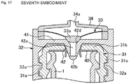
- the cap body 32 has an inner plug 41 formed to block a flow passage in a position above the inner cap 31, and a protrusion 42 is formed at the center.
- the protrusion 42 is formed protruding towards the sealing member (downwardly), and has an end in a peak shape (conical shape) and also has a content flow passage 42a formed from a midway position thereof penetrating to an outflow side of the inner plug.
- Fig. 16 is a plan view of the protrusion 42 taken from below (i.e., bottom view), and in this example, openings 42c of the content flow passage 42a are formed in the form of opening in two areas of the circumferential surface of the conical shape between a tip end 42b and a base end.
- the content flow passage 42a formed in the protrusion 42 penetrates the outflow side of the inner plug 41, and a valve 33a of the check valve 33 abuts on an opening 42d on the outflow side for opening and closing operation.
- a nozzle portion 34 having a pouring outlet 34a covering the check valve 33 is mounted to take out the contents from the pouring outlet 34a.
- a hinge cap is mounted covering the pouring outlet 34a of the nozzle portion 34 while illustration is omitted here.
- the mouth 4 of the container body 2 is sealed by the sealing member 40 during storage and the tightly closed condition is kept, thereby inhibiting content degradation and the like to a minimum.
- the cap body 32 is screwed to move the protrusion 42 formed at the center of the inner plug 41 forward to the sealing member 40 and break through the sealing member 40 with the tip end and thus unsealing is carried out. Accordingly, the cap body 32 is screwed in the inner cap 31 to a position not to hit the sealing member 40 with the tip end of the protrusion 42 during storage to allow unsealing operation by further screwing at the time of unsealing.
- a stopper or the like is preferably provided in the external screw portion 31a of the inner cap 31 to keep the screwing of the cap body 32 in a position not to hit the sealing member 40 with the tip end of the protrusion 42 during storage. With such preparation, the cap body 32 is not screwed during storage and unintended unsealing is avoided. For use, the stopper may be removed to screw the cap body 32.
- Fig. 17 is a drawing illustrating an unsealed state of the sealing member 40.
- the sealing member 40 is broken with the tip end of the protrusion 42 provided in the inner plug 41 to be unsealed.
- the tip end of the protrusion 42 has a peak shape (conical shape) and the openings 42c of the content flow passage 42a are located in the midway of the outer circumferential surface of the protrusion 42, and thus the cut fragments of the sealing member 40 do not close the openings 42c unintentionally to certainly secure the flow passage.
- the mouth 4 of the container body 2 is communicable with the outside via the content flow passage 42a provided in the protrusion 42 and the pouring outlet 34a of the nozzle portion 34 to allow pouring of the contents.
- the internal pressure of the container body 2 increases and the valve 33a of the check valve 33 in abutment on the openings 42c of the content flow passage 42a separates from the openings 42c to open the openings 42c of the content flow passage 42a.
- the contents passes through the content flow passage 42a of the protrusion 42 breaking through the sealing member 40 and is poured from the pouring outlet 34a of the nozzle portion 34 to outside.
- the internal pressure of the container body 2 decreases and the valve 33a of the check valve 33 abuts on the openings 42c of the content flow passage 42a to be in the tightly closed condition.
Landscapes
- Engineering & Computer Science (AREA)
- Mechanical Engineering (AREA)
- Ceramic Engineering (AREA)
- Closures For Containers (AREA)
- Containers And Packaging Bodies Having A Special Means To Remove Contents (AREA)
- Containers Having Bodies Formed In One Piece (AREA)
Applications Claiming Priority (4)
| Application Number | Priority Date | Filing Date | Title |
|---|---|---|---|
| JP2015236867A JP6823245B2 (ja) | 2015-12-03 | 2015-12-03 | 積層剥離容器 |
| JP2016041243A JP2017154802A (ja) | 2016-03-03 | 2016-03-03 | 積層剥離容器 |
| JP2016052673A JP6775132B2 (ja) | 2016-03-16 | 2016-03-16 | 二重容器 |
| PCT/JP2016/085883 WO2017094880A1 (fr) | 2015-12-03 | 2016-12-02 | Récipient séparable à stratification |
Publications (3)
| Publication Number | Publication Date |
|---|---|
| EP3385181A1 true EP3385181A1 (fr) | 2018-10-10 |
| EP3385181A4 EP3385181A4 (fr) | 2019-03-13 |
| EP3385181B1 EP3385181B1 (fr) | 2020-05-27 |
Family
ID=58797402
Family Applications (1)
| Application Number | Title | Priority Date | Filing Date |
|---|---|---|---|
| EP16870815.4A Active EP3385181B1 (fr) | 2015-12-03 | 2016-12-02 | Récipient séparable à stratification |
Country Status (6)
| Country | Link |
|---|---|
| US (1) | US10822135B2 (fr) |
| EP (1) | EP3385181B1 (fr) |
| KR (2) | KR20250011714A (fr) |
| CN (1) | CN108367830B (fr) |
| TW (1) | TWI704090B (fr) |
| WO (1) | WO2017094880A1 (fr) |
Families Citing this family (15)
| Publication number | Priority date | Publication date | Assignee | Title |
|---|---|---|---|---|
| EP3385181B1 (fr) * | 2015-12-03 | 2020-05-27 | Kyoraku Co., Ltd. | Récipient séparable à stratification |
| JP7092980B2 (ja) * | 2017-01-30 | 2022-06-29 | キョーラク株式会社 | キャップ及び積層剥離容器 |
| EP3597562B1 (fr) * | 2017-03-15 | 2021-10-13 | Kyoraku Co., Ltd. | Récipient anti-délaminage |
| JP7004898B2 (ja) | 2017-08-21 | 2022-02-10 | キョーラク株式会社 | 積層剥離容器及び積層剥離容器のエアリーク検査方法 |
| JP7231818B2 (ja) * | 2017-12-21 | 2023-03-02 | キョーラク株式会社 | キャップ及び積層剥離容器 |
| USD863590S1 (en) * | 2018-04-17 | 2019-10-15 | Jbl Radical Innovations, Llc | Dispensing vial |
| US10966440B2 (en) * | 2019-01-05 | 2021-04-06 | Foremost Technologies and Products, Inc. | High pressure processing of foods and food supplements |
| CN109760938B (zh) * | 2019-01-29 | 2023-09-19 | 中山市华宝勒生活用品有限公司 | 一种可调节倒式定量出液容器 |
| WO2020250467A1 (fr) * | 2019-06-14 | 2020-12-17 | 株式会社ダイゾー | Appareil d'évacuation |
| US11613397B2 (en) | 2019-09-12 | 2023-03-28 | Owens-Brockway Glass Container Inc. | Ring pull cap rim for glass containers |
| MX2021002445A (es) * | 2020-03-02 | 2021-10-01 | Fna Group Inc | Sistema de llenado de fluidos. |
| US11873159B2 (en) * | 2020-08-19 | 2024-01-16 | Mark Steele | Package having a hingeable valve mechanism |
| CN114834771B (zh) * | 2021-02-02 | 2025-01-24 | 塞舌尔商日勤包装科技股份有限公司 | 积层剥离容器 |
| CN114955209A (zh) * | 2021-02-25 | 2022-08-30 | 叙事有限公司 | 具有可拆卸的开口封闭件及密封装置的袋式容器 |
| US11591151B2 (en) | 2021-07-02 | 2023-02-28 | Owens-Brockway Glass Container Inc. | Pressure relief blow-out plugs and related packages |
Family Cites Families (41)
| Publication number | Priority date | Publication date | Assignee | Title |
|---|---|---|---|---|
| JPH0430144Y2 (fr) * | 1986-05-23 | 1992-07-21 | ||
| JPH0245967A (ja) * | 1988-08-08 | 1990-02-15 | Hitachi Cable Ltd | 半導体装置用リードフレームの製造方法 |
| JPH069977Y2 (ja) * | 1988-09-27 | 1994-03-16 | 株式会社吉野工業所 | クリーム状物吐出容器 |
| US5301838A (en) * | 1991-01-23 | 1994-04-12 | Continental Pet Technologies, Inc. | Multilayer bottle with separable inner layer and method for forming same |
| JPH04267727A (ja) | 1991-02-05 | 1992-09-24 | Keisuke Ito | 多層成形容器及びその製造方法 |
| JP2557246Y2 (ja) | 1991-03-29 | 1997-12-10 | 株式会社吉野工業所 | 積層ボトル |
| JP3158494B2 (ja) * | 1991-06-19 | 2001-04-23 | 凸版印刷株式会社 | 蓋 材 |
| JPH07112749A (ja) | 1993-08-23 | 1995-05-02 | Yoshino Kogyosho Co Ltd | チューブ容器 |
| JP3650175B2 (ja) | 1995-09-13 | 2005-05-18 | 株式会社吉野工業所 | 積層プラスチックボトル |
| EP1092632B1 (fr) | 1995-03-10 | 2003-11-19 | Yoshino Kogyosho Co., Ltd. | Procédé et dispositif de prédélamination d'un récipient en matériau laminé délaminable |
| JP3688373B2 (ja) * | 1995-12-22 | 2005-08-24 | 株式会社吉野工業所 | 押出注出可能とした積層剥離容器 |
| JP4535259B2 (ja) * | 2004-09-30 | 2010-09-01 | 株式会社吉野工業所 | ブロー成形容器 |
| JP2007001651A (ja) * | 2005-06-27 | 2007-01-11 | Dainippon Printing Co Ltd | 容器 |
| JP4800117B2 (ja) | 2006-06-05 | 2011-10-26 | 株式会社吉野工業所 | 合成樹脂製ボトル |
| WO2008117866A1 (fr) * | 2007-03-28 | 2008-10-02 | Fujimori Kogyo Co., Ltd. | Procédé et appareil de fabrication d'un film d'étanchéité, procédé de fabrication d'un conteneur avec un joint d'étanchéité interne, matériau d'étanchéité interne, et procédé de scellement étanche d'un cont |
| CN201217541Y (zh) * | 2008-05-12 | 2009-04-08 | 广州华根包装产品有限公司 | 一种改进的密封瓶 |
| JP5288175B2 (ja) | 2008-11-28 | 2013-09-11 | 株式会社吉野工業所 | 合成樹脂製二重容器 |
| JP5477721B2 (ja) | 2010-09-30 | 2014-04-23 | 株式会社吉野工業所 | キャップ付き容器 |
| KR20120058706A (ko) * | 2010-11-30 | 2012-06-08 | 이정민 | 이종물질 배출장치 |
| JP6336702B2 (ja) | 2011-08-05 | 2018-06-06 | キッコーマン株式会社 | 吐出容器 |
| JP5830333B2 (ja) | 2011-09-29 | 2015-12-09 | 株式会社吉野工業所 | 吐出容器 |
| JP5771496B2 (ja) | 2011-09-29 | 2015-09-02 | 株式会社吉野工業所 | 吐出容器 |
| CH708556A2 (de) * | 2013-09-05 | 2015-03-13 | Deltona Innovations Ag | Selbstöffnender Kunststoffverschluss. |
| US10308389B2 (en) | 2013-11-27 | 2019-06-04 | Kyoraku Co., Ltd. | Delaminatable container |
| AU2014355545B2 (en) * | 2013-11-27 | 2018-02-08 | Kyoraku Co., Ltd. | Delamination container |
| JP6780911B2 (ja) | 2013-11-27 | 2020-11-04 | キョーラク株式会社 | 積層剥離容器 |
| ES2674380T3 (es) | 2013-11-27 | 2018-06-29 | Kyoraku Co., Ltd. | Recipiente deslaminable |
| WO2015080015A1 (fr) * | 2013-11-27 | 2015-06-04 | キョーラク株式会社 | Récipient de déstratification, son procédé de vérification de trous d'aiguille, et son procédé de traitement |
| JP6249220B2 (ja) * | 2014-01-14 | 2017-12-20 | 株式会社型システム | 流量調整でき、液垂れしない注出ノズル付き容器 |
| TWI554442B (zh) * | 2014-01-28 | 2016-10-21 | Kyoraku Co Ltd | Layers peel the container |
| KR102110129B1 (ko) * | 2014-05-14 | 2020-06-08 | 도쿄 라이트 고교 가부시키가이샤 | 캡 |
| JP6421458B2 (ja) * | 2014-05-29 | 2018-11-14 | キョーラク株式会社 | 積層剥離容器 |
| US10427821B2 (en) * | 2014-10-07 | 2019-10-01 | Kyoraku Co., Ltd. | Delaminated container manufacturing method and air leak inspection method for delaminated container |
| JP6761159B2 (ja) * | 2014-11-19 | 2020-09-23 | キョーラク株式会社 | 積層剥離容器 |
| CN107207115B (zh) * | 2015-01-23 | 2019-06-11 | 京洛株式会社 | 层叠剥离容器 |
| JP6489851B2 (ja) * | 2015-01-30 | 2019-03-27 | 株式会社吉野工業所 | 二重容器 |
| JP6548440B2 (ja) * | 2015-04-15 | 2019-07-24 | 東京ライト工業株式会社 | 容器及びキャップ |
| EP3385181B1 (fr) * | 2015-12-03 | 2020-05-27 | Kyoraku Co., Ltd. | Récipient séparable à stratification |
| CN109071059B (zh) * | 2016-04-15 | 2020-10-16 | 京洛株式会社 | 层叠剥离容器 |
| JP6559097B2 (ja) * | 2016-06-30 | 2019-08-14 | 株式会社クボタ | エンジンのオイル冷却構造 |
| JP7092980B2 (ja) * | 2017-01-30 | 2022-06-29 | キョーラク株式会社 | キャップ及び積層剥離容器 |
-
2016
- 2016-12-02 EP EP16870815.4A patent/EP3385181B1/fr active Active
- 2016-12-02 US US15/780,855 patent/US10822135B2/en active Active
- 2016-12-02 WO PCT/JP2016/085883 patent/WO2017094880A1/fr active Application Filing
- 2016-12-02 KR KR1020257000524A patent/KR20250011714A/ko active Application Filing
- 2016-12-02 CN CN201680069966.8A patent/CN108367830B/zh active Active
- 2016-12-02 TW TW105139883A patent/TWI704090B/zh active
- 2016-12-02 KR KR1020187013414A patent/KR102753353B1/ko active IP Right Grant
Also Published As
| Publication number | Publication date |
|---|---|
| TW201722790A (zh) | 2017-07-01 |
| US10822135B2 (en) | 2020-11-03 |
| KR20250011714A (ko) | 2025-01-21 |
| EP3385181B1 (fr) | 2020-05-27 |
| WO2017094880A1 (fr) | 2017-06-08 |
| KR102753353B1 (ko) | 2025-01-09 |
| KR20180089396A (ko) | 2018-08-08 |
| EP3385181A4 (fr) | 2019-03-13 |
| TWI704090B (zh) | 2020-09-11 |
| CN108367830A (zh) | 2018-08-03 |
| CN108367830B (zh) | 2022-12-23 |
| US20180370673A1 (en) | 2018-12-27 |
Similar Documents
| Publication | Publication Date | Title |
|---|---|---|
| EP3385181B1 (fr) | Récipient séparable à stratification | |
| EP3235747B1 (fr) | Récipient délaminable et procédé pour y fixer un capuchon | |
| EP3597562B1 (fr) | Récipient anti-délaminage | |
| US11427368B2 (en) | Manufacturing method for double walled container | |
| KR102590903B1 (ko) | 적층박리용기 | |
| CN114834719B (zh) | 层叠剥离容器 | |
| JP6775132B2 (ja) | 二重容器 | |
| JP2007320645A (ja) | 合成樹脂製ボトル | |
| WO2019131416A1 (fr) | Contenant séparable par stratification | |
| EP1910175B1 (fr) | Emballage doté d un couvercle étanche et procédé permettant de remplir l emballage | |
| JP2007320644A (ja) | 合成樹脂製ボトル | |
| US10786941B2 (en) | Double-layered container and method for production of the same | |
| US11377271B2 (en) | Plastic closure part with severable membrane | |
| JP2018034850A (ja) | キャップ付き容器 | |
| JP2019099212A (ja) | 積層剥離容器 | |
| WO2017073606A1 (fr) | Double contenant et son procédé de fabrication | |
| JP2020023352A (ja) | 二重容器 | |
| JP7104875B2 (ja) | 二重容器 | |
| JP2015127237A (ja) | 積層剥離容器 | |
| JP2012076786A (ja) | 開封刃付きキャップ | |
| JP2005335801A (ja) | キャップ付き容器 | |
| JP3136015U (ja) | 包装用容器 |
Legal Events
| Date | Code | Title | Description |
|---|---|---|---|
| STAA | Information on the status of an ep patent application or granted ep patent |
Free format text: STATUS: THE INTERNATIONAL PUBLICATION HAS BEEN MADE |
|
| PUAI | Public reference made under article 153(3) epc to a published international application that has entered the european phase |
Free format text: ORIGINAL CODE: 0009012 |
|
| STAA | Information on the status of an ep patent application or granted ep patent |
Free format text: STATUS: REQUEST FOR EXAMINATION WAS MADE |
|
| 17P | Request for examination filed |
Effective date: 20180614 |
|
| AK | Designated contracting states |
Kind code of ref document: A1 Designated state(s): AL AT BE BG CH CY CZ DE DK EE ES FI FR GB GR HR HU IE IS IT LI LT LU LV MC MK MT NL NO PL PT RO RS SE SI SK SM TR |
|
| AX | Request for extension of the european patent |
Extension state: BA ME |
|
| RIC1 | Information provided on ipc code assigned before grant |
Ipc: B67B 3/22 20060101ALI20181030BHEP Ipc: B65D 83/00 20060101ALI20181030BHEP Ipc: B65D 1/02 20060101AFI20181030BHEP |
|
| A4 | Supplementary search report drawn up and despatched |
Effective date: 20190207 |
|
| DAV | Request for validation of the european patent (deleted) | ||
| DAX | Request for extension of the european patent (deleted) | ||
| RIC1 | Information provided on ipc code assigned before grant |
Ipc: B67B 3/22 20060101ALI20190201BHEP Ipc: B65D 83/00 20060101ALI20190201BHEP Ipc: B65D 1/02 20060101AFI20190201BHEP |
|
| GRAP | Despatch of communication of intention to grant a patent |
Free format text: ORIGINAL CODE: EPIDOSNIGR1 |
|
| STAA | Information on the status of an ep patent application or granted ep patent |
Free format text: STATUS: GRANT OF PATENT IS INTENDED |
|
| INTG | Intention to grant announced |
Effective date: 20191213 |
|
| GRAS | Grant fee paid |
Free format text: ORIGINAL CODE: EPIDOSNIGR3 |
|
| GRAA | (expected) grant |
Free format text: ORIGINAL CODE: 0009210 |
|
| STAA | Information on the status of an ep patent application or granted ep patent |
Free format text: STATUS: THE PATENT HAS BEEN GRANTED |
|
| AK | Designated contracting states |
Kind code of ref document: B1 Designated state(s): AL AT BE BG CH CY CZ DE DK EE ES FI FR GB GR HR HU IE IS IT LI LT LU LV MC MK MT NL NO PL PT RO RS SE SI SK SM TR |
|
| REG | Reference to a national code |
Ref country code: GB Ref legal event code: FG4D |
|
| REG | Reference to a national code |
Ref country code: CH Ref legal event code: EP |
|
| REG | Reference to a national code |
Ref country code: AT Ref legal event code: REF Ref document number: 1274327 Country of ref document: AT Kind code of ref document: T Effective date: 20200615 |
|
| REG | Reference to a national code |
Ref country code: DE Ref legal event code: R096 Ref document number: 602016037259 Country of ref document: DE |
|
| REG | Reference to a national code |
Ref country code: LT Ref legal event code: MG4D |
|
| PG25 | Lapsed in a contracting state [announced via postgrant information from national office to epo] |
Ref country code: LT Free format text: LAPSE BECAUSE OF FAILURE TO SUBMIT A TRANSLATION OF THE DESCRIPTION OR TO PAY THE FEE WITHIN THE PRESCRIBED TIME-LIMIT Effective date: 20200527 Ref country code: SE Free format text: LAPSE BECAUSE OF FAILURE TO SUBMIT A TRANSLATION OF THE DESCRIPTION OR TO PAY THE FEE WITHIN THE PRESCRIBED TIME-LIMIT Effective date: 20200527 Ref country code: PT Free format text: LAPSE BECAUSE OF FAILURE TO SUBMIT A TRANSLATION OF THE DESCRIPTION OR TO PAY THE FEE WITHIN THE PRESCRIBED TIME-LIMIT Effective date: 20200928 Ref country code: NO Free format text: LAPSE BECAUSE OF FAILURE TO SUBMIT A TRANSLATION OF THE DESCRIPTION OR TO PAY THE FEE WITHIN THE PRESCRIBED TIME-LIMIT Effective date: 20200827 Ref country code: IS Free format text: LAPSE BECAUSE OF FAILURE TO SUBMIT A TRANSLATION OF THE DESCRIPTION OR TO PAY THE FEE WITHIN THE PRESCRIBED TIME-LIMIT Effective date: 20200927 Ref country code: GR Free format text: LAPSE BECAUSE OF FAILURE TO SUBMIT A TRANSLATION OF THE DESCRIPTION OR TO PAY THE FEE WITHIN THE PRESCRIBED TIME-LIMIT Effective date: 20200828 Ref country code: FI Free format text: LAPSE BECAUSE OF FAILURE TO SUBMIT A TRANSLATION OF THE DESCRIPTION OR TO PAY THE FEE WITHIN THE PRESCRIBED TIME-LIMIT Effective date: 20200527 |
|
| REG | Reference to a national code |
Ref country code: NL Ref legal event code: MP Effective date: 20200527 |
|
| PG25 | Lapsed in a contracting state [announced via postgrant information from national office to epo] |
Ref country code: HR Free format text: LAPSE BECAUSE OF FAILURE TO SUBMIT A TRANSLATION OF THE DESCRIPTION OR TO PAY THE FEE WITHIN THE PRESCRIBED TIME-LIMIT Effective date: 20200527 Ref country code: LV Free format text: LAPSE BECAUSE OF FAILURE TO SUBMIT A TRANSLATION OF THE DESCRIPTION OR TO PAY THE FEE WITHIN THE PRESCRIBED TIME-LIMIT Effective date: 20200527 Ref country code: BG Free format text: LAPSE BECAUSE OF FAILURE TO SUBMIT A TRANSLATION OF THE DESCRIPTION OR TO PAY THE FEE WITHIN THE PRESCRIBED TIME-LIMIT Effective date: 20200827 Ref country code: RS Free format text: LAPSE BECAUSE OF FAILURE TO SUBMIT A TRANSLATION OF THE DESCRIPTION OR TO PAY THE FEE WITHIN THE PRESCRIBED TIME-LIMIT Effective date: 20200527 |
|
| REG | Reference to a national code |
Ref country code: AT Ref legal event code: MK05 Ref document number: 1274327 Country of ref document: AT Kind code of ref document: T Effective date: 20200527 |
|
| PG25 | Lapsed in a contracting state [announced via postgrant information from national office to epo] |
Ref country code: NL Free format text: LAPSE BECAUSE OF FAILURE TO SUBMIT A TRANSLATION OF THE DESCRIPTION OR TO PAY THE FEE WITHIN THE PRESCRIBED TIME-LIMIT Effective date: 20200527 Ref country code: AL Free format text: LAPSE BECAUSE OF FAILURE TO SUBMIT A TRANSLATION OF THE DESCRIPTION OR TO PAY THE FEE WITHIN THE PRESCRIBED TIME-LIMIT Effective date: 20200527 |
|
| PG25 | Lapsed in a contracting state [announced via postgrant information from national office to epo] |
Ref country code: CZ Free format text: LAPSE BECAUSE OF FAILURE TO SUBMIT A TRANSLATION OF THE DESCRIPTION OR TO PAY THE FEE WITHIN THE PRESCRIBED TIME-LIMIT Effective date: 20200527 Ref country code: RO Free format text: LAPSE BECAUSE OF FAILURE TO SUBMIT A TRANSLATION OF THE DESCRIPTION OR TO PAY THE FEE WITHIN THE PRESCRIBED TIME-LIMIT Effective date: 20200527 Ref country code: AT Free format text: LAPSE BECAUSE OF FAILURE TO SUBMIT A TRANSLATION OF THE DESCRIPTION OR TO PAY THE FEE WITHIN THE PRESCRIBED TIME-LIMIT Effective date: 20200527 Ref country code: EE Free format text: LAPSE BECAUSE OF FAILURE TO SUBMIT A TRANSLATION OF THE DESCRIPTION OR TO PAY THE FEE WITHIN THE PRESCRIBED TIME-LIMIT Effective date: 20200527 Ref country code: IT Free format text: LAPSE BECAUSE OF FAILURE TO SUBMIT A TRANSLATION OF THE DESCRIPTION OR TO PAY THE FEE WITHIN THE PRESCRIBED TIME-LIMIT Effective date: 20200527 Ref country code: SM Free format text: LAPSE BECAUSE OF FAILURE TO SUBMIT A TRANSLATION OF THE DESCRIPTION OR TO PAY THE FEE WITHIN THE PRESCRIBED TIME-LIMIT Effective date: 20200527 Ref country code: DK Free format text: LAPSE BECAUSE OF FAILURE TO SUBMIT A TRANSLATION OF THE DESCRIPTION OR TO PAY THE FEE WITHIN THE PRESCRIBED TIME-LIMIT Effective date: 20200527 Ref country code: ES Free format text: LAPSE BECAUSE OF FAILURE TO SUBMIT A TRANSLATION OF THE DESCRIPTION OR TO PAY THE FEE WITHIN THE PRESCRIBED TIME-LIMIT Effective date: 20200527 |
|
| PG25 | Lapsed in a contracting state [announced via postgrant information from national office to epo] |
Ref country code: SK Free format text: LAPSE BECAUSE OF FAILURE TO SUBMIT A TRANSLATION OF THE DESCRIPTION OR TO PAY THE FEE WITHIN THE PRESCRIBED TIME-LIMIT Effective date: 20200527 Ref country code: PL Free format text: LAPSE BECAUSE OF FAILURE TO SUBMIT A TRANSLATION OF THE DESCRIPTION OR TO PAY THE FEE WITHIN THE PRESCRIBED TIME-LIMIT Effective date: 20200527 |
|
| REG | Reference to a national code |
Ref country code: DE Ref legal event code: R097 Ref document number: 602016037259 Country of ref document: DE |
|
| PLBE | No opposition filed within time limit |
Free format text: ORIGINAL CODE: 0009261 |
|
| STAA | Information on the status of an ep patent application or granted ep patent |
Free format text: STATUS: NO OPPOSITION FILED WITHIN TIME LIMIT |
|
| 26N | No opposition filed |
Effective date: 20210302 |
|
| PG25 | Lapsed in a contracting state [announced via postgrant information from national office to epo] |
Ref country code: SI Free format text: LAPSE BECAUSE OF FAILURE TO SUBMIT A TRANSLATION OF THE DESCRIPTION OR TO PAY THE FEE WITHIN THE PRESCRIBED TIME-LIMIT Effective date: 20200527 |
|
| REG | Reference to a national code |
Ref country code: CH Ref legal event code: PL |
|
| PG25 | Lapsed in a contracting state [announced via postgrant information from national office to epo] |
Ref country code: MC Free format text: LAPSE BECAUSE OF FAILURE TO SUBMIT A TRANSLATION OF THE DESCRIPTION OR TO PAY THE FEE WITHIN THE PRESCRIBED TIME-LIMIT Effective date: 20200527 |
|
| REG | Reference to a national code |
Ref country code: BE Ref legal event code: MM Effective date: 20201231 |
|
| PG25 | Lapsed in a contracting state [announced via postgrant information from national office to epo] |
Ref country code: IE Free format text: LAPSE BECAUSE OF NON-PAYMENT OF DUE FEES Effective date: 20201202 Ref country code: LU Free format text: LAPSE BECAUSE OF NON-PAYMENT OF DUE FEES Effective date: 20201202 |
|
| PG25 | Lapsed in a contracting state [announced via postgrant information from national office to epo] |
Ref country code: CH Free format text: LAPSE BECAUSE OF NON-PAYMENT OF DUE FEES Effective date: 20201231 Ref country code: LI Free format text: LAPSE BECAUSE OF NON-PAYMENT OF DUE FEES Effective date: 20201231 |
|
| PG25 | Lapsed in a contracting state [announced via postgrant information from national office to epo] |
Ref country code: TR Free format text: LAPSE BECAUSE OF FAILURE TO SUBMIT A TRANSLATION OF THE DESCRIPTION OR TO PAY THE FEE WITHIN THE PRESCRIBED TIME-LIMIT Effective date: 20200527 Ref country code: MT Free format text: LAPSE BECAUSE OF FAILURE TO SUBMIT A TRANSLATION OF THE DESCRIPTION OR TO PAY THE FEE WITHIN THE PRESCRIBED TIME-LIMIT Effective date: 20200527 Ref country code: CY Free format text: LAPSE BECAUSE OF FAILURE TO SUBMIT A TRANSLATION OF THE DESCRIPTION OR TO PAY THE FEE WITHIN THE PRESCRIBED TIME-LIMIT Effective date: 20200527 |
|
| PG25 | Lapsed in a contracting state [announced via postgrant information from national office to epo] |
Ref country code: MK Free format text: LAPSE BECAUSE OF FAILURE TO SUBMIT A TRANSLATION OF THE DESCRIPTION OR TO PAY THE FEE WITHIN THE PRESCRIBED TIME-LIMIT Effective date: 20200527 |
|
| PG25 | Lapsed in a contracting state [announced via postgrant information from national office to epo] |
Ref country code: BE Free format text: LAPSE BECAUSE OF NON-PAYMENT OF DUE FEES Effective date: 20201231 |
|
| PGFP | Annual fee paid to national office [announced via postgrant information from national office to epo] |
Ref country code: GB Payment date: 20231220 Year of fee payment: 8 |
|
| PGFP | Annual fee paid to national office [announced via postgrant information from national office to epo] |
Ref country code: FR Payment date: 20231222 Year of fee payment: 8 |
|
| PGFP | Annual fee paid to national office [announced via postgrant information from national office to epo] |
Ref country code: DE Payment date: 20241210 Year of fee payment: 9 |