EP3351212B2 - Outil d'insertion de lentille intraoculaire - Google Patents
Outil d'insertion de lentille intraoculaire Download PDFInfo
- Publication number
- EP3351212B2 EP3351212B2 EP16846585.4A EP16846585A EP3351212B2 EP 3351212 B2 EP3351212 B2 EP 3351212B2 EP 16846585 A EP16846585 A EP 16846585A EP 3351212 B2 EP3351212 B2 EP 3351212B2
- Authority
- EP
- European Patent Office
- Prior art keywords
- intraocular lens
- tip end
- pushing member
- end part
- guide
- Prior art date
- Legal status (The legal status is an assumption and is not a legal conclusion. Google has not performed a legal analysis and makes no representation as to the accuracy of the status listed.)
- Active
Links
- 238000003780 insertion Methods 0.000 title description 4
- 230000037431 insertion Effects 0.000 title description 4
- 230000003287 optical effect Effects 0.000 claims description 144
- 230000007246 mechanism Effects 0.000 claims description 20
- 230000002093 peripheral effect Effects 0.000 claims description 16
- 238000011144 upstream manufacturing Methods 0.000 claims description 7
- 230000036316 preload Effects 0.000 claims description 4
- 230000000452 restraining effect Effects 0.000 claims 1
- 238000002347 injection Methods 0.000 description 58
- 239000007924 injection Substances 0.000 description 58
- 230000000052 comparative effect Effects 0.000 description 13
- 210000001508 eye Anatomy 0.000 description 10
- 238000000034 method Methods 0.000 description 9
- 238000005452 bending Methods 0.000 description 6
- 238000006073 displacement reaction Methods 0.000 description 6
- 230000005489 elastic deformation Effects 0.000 description 6
- 230000000694 effects Effects 0.000 description 5
- 230000008569 process Effects 0.000 description 5
- 239000003190 viscoelastic substance Substances 0.000 description 5
- 229940006076 viscoelastic substance Drugs 0.000 description 5
- 230000003247 decreasing effect Effects 0.000 description 4
- 238000003825 pressing Methods 0.000 description 4
- 239000007779 soft material Substances 0.000 description 4
- 238000013461 design Methods 0.000 description 3
- 208000002177 Cataract Diseases 0.000 description 2
- NIXOWILDQLNWCW-UHFFFAOYSA-N acrylic acid group Chemical group C(C=C)(=O)O NIXOWILDQLNWCW-UHFFFAOYSA-N 0.000 description 2
- 238000013459 approach Methods 0.000 description 2
- 210000005252 bulbus oculi Anatomy 0.000 description 2
- 238000006243 chemical reaction Methods 0.000 description 2
- 239000000463 material Substances 0.000 description 2
- 239000011347 resin Substances 0.000 description 2
- 229920005989 resin Polymers 0.000 description 2
- 229920002379 silicone rubber Polymers 0.000 description 2
- 238000001356 surgical procedure Methods 0.000 description 2
- 229920002385 Sodium hyaluronate Polymers 0.000 description 1
- 230000008901 benefit Effects 0.000 description 1
- 230000008859 change Effects 0.000 description 1
- 239000000470 constituent Substances 0.000 description 1
- 230000001419 dependent effect Effects 0.000 description 1
- 238000004945 emulsification Methods 0.000 description 1
- 210000000887 face Anatomy 0.000 description 1
- 238000004519 manufacturing process Methods 0.000 description 1
- 238000012986 modification Methods 0.000 description 1
- 230000004048 modification Effects 0.000 description 1
- 238000009751 slip forming Methods 0.000 description 1
- 229940010747 sodium hyaluronate Drugs 0.000 description 1
- YWIVKILSMZOHHF-QJZPQSOGSA-N sodium;(2s,3s,4s,5r,6r)-6-[(2s,3r,4r,5s,6r)-3-acetamido-2-[(2s,3s,4r,5r,6r)-6-[(2r,3r,4r,5s,6r)-3-acetamido-2,5-dihydroxy-6-(hydroxymethyl)oxan-4-yl]oxy-2-carboxy-4,5-dihydroxyoxan-3-yl]oxy-5-hydroxy-6-(hydroxymethyl)oxan-4-yl]oxy-3,4,5-trihydroxyoxane-2- Chemical compound [Na+].CC(=O)N[C@H]1[C@H](O)O[C@H](CO)[C@@H](O)[C@@H]1O[C@H]1[C@H](O)[C@@H](O)[C@H](O[C@H]2[C@@H]([C@@H](O[C@H]3[C@@H]([C@@H](O)[C@H](O)[C@H](O3)C(O)=O)O)[C@H](O)[C@@H](CO)O2)NC(C)=O)[C@@H](C(O)=O)O1 YWIVKILSMZOHHF-QJZPQSOGSA-N 0.000 description 1
Images


Classifications
-
- A—HUMAN NECESSITIES
- A61—MEDICAL OR VETERINARY SCIENCE; HYGIENE
- A61F—FILTERS IMPLANTABLE INTO BLOOD VESSELS; PROSTHESES; DEVICES PROVIDING PATENCY TO, OR PREVENTING COLLAPSING OF, TUBULAR STRUCTURES OF THE BODY, e.g. STENTS; ORTHOPAEDIC, NURSING OR CONTRACEPTIVE DEVICES; FOMENTATION; TREATMENT OR PROTECTION OF EYES OR EARS; BANDAGES, DRESSINGS OR ABSORBENT PADS; FIRST-AID KITS
- A61F2/00—Filters implantable into blood vessels; Prostheses, i.e. artificial substitutes or replacements for parts of the body; Appliances for connecting them with the body; Devices providing patency to, or preventing collapsing of, tubular structures of the body, e.g. stents
- A61F2/02—Prostheses implantable into the body
- A61F2/14—Eye parts, e.g. lenses, corneal implants; Implanting instruments specially adapted therefor; Artificial eyes
- A61F2/16—Intraocular lenses
- A61F2/1662—Instruments for inserting intraocular lenses into the eye
- A61F2/167—Instruments for inserting intraocular lenses into the eye with pushable plungers
-
- A—HUMAN NECESSITIES
- A61—MEDICAL OR VETERINARY SCIENCE; HYGIENE
- A61F—FILTERS IMPLANTABLE INTO BLOOD VESSELS; PROSTHESES; DEVICES PROVIDING PATENCY TO, OR PREVENTING COLLAPSING OF, TUBULAR STRUCTURES OF THE BODY, e.g. STENTS; ORTHOPAEDIC, NURSING OR CONTRACEPTIVE DEVICES; FOMENTATION; TREATMENT OR PROTECTION OF EYES OR EARS; BANDAGES, DRESSINGS OR ABSORBENT PADS; FIRST-AID KITS
- A61F2/00—Filters implantable into blood vessels; Prostheses, i.e. artificial substitutes or replacements for parts of the body; Appliances for connecting them with the body; Devices providing patency to, or preventing collapsing of, tubular structures of the body, e.g. stents
- A61F2/02—Prostheses implantable into the body
- A61F2/14—Eye parts, e.g. lenses, corneal implants; Implanting instruments specially adapted therefor; Artificial eyes
- A61F2/16—Intraocular lenses
- A61F2/1662—Instruments for inserting intraocular lenses into the eye
- A61F2/1667—Instruments for inserting intraocular lenses into the eye with rotatable plungers
-
- A—HUMAN NECESSITIES
- A61—MEDICAL OR VETERINARY SCIENCE; HYGIENE
- A61F—FILTERS IMPLANTABLE INTO BLOOD VESSELS; PROSTHESES; DEVICES PROVIDING PATENCY TO, OR PREVENTING COLLAPSING OF, TUBULAR STRUCTURES OF THE BODY, e.g. STENTS; ORTHOPAEDIC, NURSING OR CONTRACEPTIVE DEVICES; FOMENTATION; TREATMENT OR PROTECTION OF EYES OR EARS; BANDAGES, DRESSINGS OR ABSORBENT PADS; FIRST-AID KITS
- A61F2/00—Filters implantable into blood vessels; Prostheses, i.e. artificial substitutes or replacements for parts of the body; Appliances for connecting them with the body; Devices providing patency to, or preventing collapsing of, tubular structures of the body, e.g. stents
- A61F2/02—Prostheses implantable into the body
- A61F2/14—Eye parts, e.g. lenses, corneal implants; Implanting instruments specially adapted therefor; Artificial eyes
- A61F2/16—Intraocular lenses
- A61F2/1662—Instruments for inserting intraocular lenses into the eye
- A61F2/1672—Instruments for inserting intraocular lenses into the eye with a two-stage plunger, e.g. rotatable and pushable or rotatable at different speeds
-
- A—HUMAN NECESSITIES
- A61—MEDICAL OR VETERINARY SCIENCE; HYGIENE
- A61F—FILTERS IMPLANTABLE INTO BLOOD VESSELS; PROSTHESES; DEVICES PROVIDING PATENCY TO, OR PREVENTING COLLAPSING OF, TUBULAR STRUCTURES OF THE BODY, e.g. STENTS; ORTHOPAEDIC, NURSING OR CONTRACEPTIVE DEVICES; FOMENTATION; TREATMENT OR PROTECTION OF EYES OR EARS; BANDAGES, DRESSINGS OR ABSORBENT PADS; FIRST-AID KITS
- A61F2/00—Filters implantable into blood vessels; Prostheses, i.e. artificial substitutes or replacements for parts of the body; Appliances for connecting them with the body; Devices providing patency to, or preventing collapsing of, tubular structures of the body, e.g. stents
- A61F2/02—Prostheses implantable into the body
- A61F2/14—Eye parts, e.g. lenses, corneal implants; Implanting instruments specially adapted therefor; Artificial eyes
- A61F2/16—Intraocular lenses
- A61F2/1662—Instruments for inserting intraocular lenses into the eye
- A61F2/1678—Instruments for inserting intraocular lenses into the eye with a separate cartridge or other lens setting part for storage of a lens, e.g. preloadable for shipping
-
- A—HUMAN NECESSITIES
- A61—MEDICAL OR VETERINARY SCIENCE; HYGIENE
- A61F—FILTERS IMPLANTABLE INTO BLOOD VESSELS; PROSTHESES; DEVICES PROVIDING PATENCY TO, OR PREVENTING COLLAPSING OF, TUBULAR STRUCTURES OF THE BODY, e.g. STENTS; ORTHOPAEDIC, NURSING OR CONTRACEPTIVE DEVICES; FOMENTATION; TREATMENT OR PROTECTION OF EYES OR EARS; BANDAGES, DRESSINGS OR ABSORBENT PADS; FIRST-AID KITS
- A61F9/00—Methods or devices for treatment of the eyes; Devices for putting-in contact lenses; Devices to correct squinting; Apparatus to guide the blind; Protective devices for the eyes, carried on the body or in the hand
- A61F9/007—Methods or devices for eye surgery
- A61F9/00736—Instruments for removal of intra-ocular material or intra-ocular injection, e.g. cataract instruments
Definitions
- the present invention relates to an intraocular lens injector used for injecting an intraocular lens into an eye.
- a cataract surgery it is widely practiced to extract a white cloudy lens by ultrasonic emulsification and suction and then inject the intraocular lens into the eye. Further, in recent years, in order to realize minimally invasive cataract surgery with less burden on an eye, a one-piece type intraocular lens made of a soft material such as silicone elastomer or soft acrylic is injected into the eye in a small folded state.
- the one-piece type intraocular lens has an optical portion that performs a lens function and a pair of support portions that extend from the optical portion, and an entire intraocular lens is made of a flexible material.
- an intraocular lens injector for handling the one-piece type intraocular lens
- an injector having a function of folding an intraocular lens so as to embrace a pair of support portions with an optical portion in order to improve operability for a surgeon to inject the intraocular lens as much as possible (for example, see patent document 1).
- intraocular lens injector it is necessary to fold the optical portion roundly in a state that tip end parts of the respective support portions are placed on a surface of the optical portion.
- conventional intraocular lens injectors include the one having a pushing member which pushes out an intraocular lens and which folds the intraocular lens when the intraocular lens is pushed out by the pushing member.
- EP 2 286 764 A1 shows a cassette for receiving an intraocular lens, wherein the cassette is formed for inserting into a lens injector device.
- EP 2 161 004 A1 shows an intraocular lens insertion device which is capable of folding an intraocular lens into a predetermined shape.
- CA 2938660 A1 shows an injector for an intraocular lens in which a lens support part is set to an appropriate position on a lens holder.
- WO 2015/012312 A1 shows an intraocular lens inserting instrument in which a shape of a support is stabilized after insertion.
- Patent Document 1 Japanese Unexamined Patent Publication No. 2011-255029
- the conventional intraocular lens injector involves a problem that when the intraocular lens is pushed out by the pushing member, the tip end part of the support portion is caught on an edge of the optical portion or the like, and the tip end part of the support portion is not placed smoothly on the surface of the optical portion.
- a main object of the present invention is to provide an intraocular lens injector capable of surely placing the tip end part of the support portion on the surface of the optical portion when the intraocular lens is folded so as to embrace the support portion with the optical portion.
- the tip end part of the support portions when folding the intraocular lens so as to embrace the support portions with the optical portion, the tip end part of the support portions can be securely placed on the surface of the optical portion.
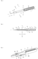
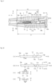
- FIG. 1 is a perspective view showing an overall structure of an intraocular lens injector according to an embodiment of the present invention
- FIG. 2 is a side sectional view showing the overall structure of the intraocular lens injector according to an embodiment of the present invention.
- An intraocular lens injector 1 shown in the figure is provided as a disposable product, and is used when injecting the intraocular lens into the eye.
- the intraocular lens injector 1 is of a preload type in which an intraocular lens is preset.
- the intraocular lens is preset on the lens setting portion described later in the stage of shipping the intraocular lens injector 1 from a factory.
- X1 direction is set as a tip end side (front side)
- X2 direction is set as a rear end side (rear side)
- Y1 direction is set as a right side (right side)
- Y2 direction is set as a left side (left side)
- Z1 direction is set as an upper side (upper side)
- Z2 direction is set as a lower side (lower side).
- the X1 direction and the X2 direction correspond to a direction of a central axis of the intraocular lens injector 1 (hereinafter also referred to simply as a "central axis direction")
- the Y1 direction and the Y2 direction correspond to a width direction (left-right direction) of the intraocular lens injector 1
- the Z1 direction and the Z2 direction correspond to a height direction (vertical direction) of the intraocular lens injector 1.
- a plane parallel to the X1 direction, the X2 direction, the Y1 direction and the Y2 direction is set as a horizontal plane
- a plane perpendicular to the horizontal plane is set as a vertical plane.
- Reference symbol J in the figure indicates the central axis of the intraocular lens injector 1.
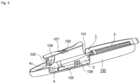
- the intraocular lens injector 1 is provided to a user in a state of being housed in a case 100.
- the case 100 is made of resin.
- the case 100 is structured to open upward so that the intraocular lens injector 1 can be attached and detached.
- the case 100 is formed with an opening / closing cover 101 for partially closing an upper part of the case 100 and an injection cover 102 for opening / closing together with the opening / closing cover 101.
- the case 100 has a space capable of housing the intraocular lens injector 1, in which the intraocular lens injector 1 is housed.
- the opening / closing cover 101 is in a closed state ( FIG. 3 ), and when the intraocular lens injector 1 is taken out from the case 100, the opening / closing cover 101 is in an open state ( FIG. 4 ).
- the opening / closing cover 101 is in a closed state, the intraocular lens injector 1 housed in the case 100 is pressed from above by the opening / closing cover 101.
- the opening / closing cover 101 is in an open state, the upper part of the case 100 is opened.
- An opening / closing operation of the opening / closing cover 101 is performed by a manufacturer or the user of the intraocular lens injector 1.
- the opening / closing cover 101 includes a hooking portion 103.
- the hooking portion 103 is a portion for hooking a user's finger when opening / closing the opening / closing cover 101.
- a slit 104 is formed in the opening / closing cover 101.
- the slit 104 is formed in the vicinity of the hooking portion 103.
- a protrusion 105 is formed in the case 100 as shown in FIG. 4 . The protrusion 105 is engaged with the slit 104 when the opening / closing cover 101 is closed, thereby holding the opening / closing cover 101 in a closed state.
- the injection lid 102 is for injecting a viscoelastic substance.
- a small hole is formed in the injection lid 102, and a part of the injection lid 102 is formed in a funnel shape around this hole.
- the injection lid 102 is partially connected to the opening / closing cover 101 so as to move together with the opening / closing cover 101.
- the case 100 is marked with numbers 106, 107, and 108. Numbers attached to each of the marks 106, 107, and 108 indicate procedures of work to be performed by the user when taking out the intraocular lens injector 1 from the case 100. Further, arrows attached to the marks 107 and 108 indicate directions of work to be performed by the user. Specifically, the mark 106 with the number "1" attached thereto, indicates that the operation of injecting the viscoelastic substance through the injection lid 102 should be performed.
- the mark 107 with the numeral "2" attached thereto indicates that the operation of opening the opening / closing cover 101 in the direction of the arrow should be performed
- the mark 108 with the numeral "3" attached thereto indicates that the operation of taking out the intraocular lens injector 1 in the direction of the arrow should be performed.
- the intraocular lens injector 1 roughly includes an injector main body 2, an operation part 3, an injection tube 4, and a pushing member 5. Each part of the intraocular lens injector 1 is made of resin.
- the injector main body 2 is formed in a tubular shape as a whole.
- a hollow portion that allows the movement of the pushing member 5 in the X1 direction and the X2 direction is formed inside of the injector main body 2.
- a lens setting portion 6 is provided at a tip end part of the injector main body 2.
- the lens setting portion 6 is formed so as to protrude forward from an outer circumferential wall on a lower side of the injector main body 2.
- the intraocular lens 7 is set on the lens setting portion 6 (see FIG. 5 ).
- a central axis J of the intraocular lens injector 1 coincides with each central axis of the injector main body 2, the operation part 3, and the injection tube 4.
- one-piece type intraocular lens 7 made of a soft material such as silicone elastomer or soft acrylic is to be handled.
- the intraocular lens 7 has an optical portion 8 that performs an optical function and a pair (two) support portions 9a, 9b extending outwardly from the outer peripheral edge of the optical portion 8 in an arc shape.
- the optical portion 8 is formed in a circular shape in plan view.
- Each of the pair of support portions 9a, 9b is formed in an elongated arm shape.
- the structure of the lens setting portion 6 will be described in detail with reference to FIG. 5 .
- a guide slope 11 is formed on an upper surface of the lens setting portion 6.
- the guide slope 11 constitutes a guide mechanism for guiding the movement of the pushing member 5 when the pushing member 5 moves in the central axis direction of the injector main body 2.
- the guide slope 11 is formed on a moving path of the pushing member 5 in a state in which a part of the lens setting portion 6 is protruded (raised) upward.
- the guide slope 11 has an inclined portion 11a inclined with respect to a horizontal plane, a top portion 11b not inclined, and a step portion 11c perpendicular to the horizontal plane.
- the inclined portion 11a is inclined in a state in which the inclined portion 11a gradually becomes higher from the back of the lens setting portion 6 toward the front.
- the inclined portion 11a is inclined obliquely upward from the upstream side to the downstream side in the moving direction of the pushing member 5.
- the top portion 11b is formed to extend horizontally from an uppermost portion of the inclined portion 11a.
- the step portion 11c is formed in a state of falling vertically from the tip end of the top portion 11b.
- a pair of right and left recessed grooves are formed in the lens setting portion 6.
- the pair of recessed grooves are formed on the left and right side walls defining the lens setting portion 6 of the injector main body 2 so as to face each other.
- the intraocular lens 7 is set on the lens setting portion 6 having the abovementioned structure, in a state in which one of the support portions 9a is disposed in front of the lens setting portion 6 and the other support portion 9b is disposed behind the lens setting portion 6. Further, the intraocular lens 7 is approximately horizontally set (placed) on the lens setting portion 6 in a state in which a rear edge of the optical portion 8 faces the step portion 11c of the guide slope 11. In FIG. 2 , the notation of the intraocular lens 7 is omitted.
- the operation portion 3 is coaxially connected to the rear end part of the injector main body 2. In this connected state, the operation portion 3 is supported so as to be rotatable around the central axis of the injector main body 2.
- the operation portion 3 is formed into a tubular shape.
- a plurality of protrusions 3a are formed on the outer peripheral surface of the operation portion 3. Each protrusion 3a is formed in parallel to a longitudinal direction of the operation portion 3.
- the operation portion 3 is a portion rotated by a user such as an operator when the intraocular lens 7 is pushed out using the pushing member 5.
- an initial state which is a state of the intraocular lens injector 1.
- a first screw portion 3b is formed on the inner peripheral surface of the operation portion 3.
- the first screw portion 3b constitutes a female screw.
- the first screw portion 3b is formed substantially throughout the central axis direction of the operation portion 3.
- An abutting portion 3c is formed at a rear end part of the operation portion 3.
- the abutting portion 3c is formed by bending inward so as to narrow an opening diameter of the rear end part of the operation portion 3.
- the abutting portion 3c is a portion where the rear end part of a plunger portion 17 abuts so that the plunger portion 17 does not protrude rearward from the rear end part of the operation portion 3.
- An injection tube 4 functions to guide the intraocular lens 7 set on the lens setting portion 6 into an eye in a state that the intraocular lens 7 is folded into a small size when the intraocular lens 7 is injected into the eye.
- the injection tube 4 integrally has a hollow injection tube main body 4a and a narrow tubular nozzle portion 4b.
- the injection tube 4 is attached to a tip end part of the injector main body 2.
- the lens setting portion 6 of the injector main body 2 is housed in the injection tube main body 4a of the injection tube 4.
- the space inside of the injection tube main body 4a is gradually narrowed toward the nozzle portion 4b, for small folding of the intraocular lens 7 pushed out from the lens setting portion 6 to the injection tube 4.
- the intraocular lens 7 is finally rounded and folded so as to embrace the pair of support portions 9a and 9b with the optical portion 8.
- the nozzle portion 4b is formed at the tip end part of the injection tube 4.
- the tip end part of the nozzle portion 4b opens with an oblique incision. Therefore, the opening of the nozzle portion 4b faces obliquely downward.
- the tip end part of the nozzle portion 4b is a portion to be inserted into an incisional wound of the eyeball when the intraocular lens 7 is injected into the eye using the intraocular lens injector 1.
- An injection portion 4c is formed on an upper wall of the injection tube main body 4a, and a through hole 4d is formed on a lower wall of the injection tube main body 4a.
- the injection portion 4c is a portion for injecting a viscoelastic substance (for example, sodium hyaluronate etc.).
- the through hole 4d is a portion into which a pin (not shown) provided vertically erect on the bottom of the abovementioned case 100 is inserted. Such a pin is disposed to protrude through the through hole 4d in the vicinity of a base end portion of the support portion 9b, when the intraocular lens injector 1 incorporating the intraocular lens 7 therein, is housed in the case 100. Thereby, in a state in which the intraocular lens injector 1 is housed in the case 100, the movement of the intraocular lens 7 is suppressed so that the position of the intraocular lens 7 does not largely deviate in the lens setting portion 6.
- the pushing member 5 is provided movably in the central axis direction of the injector main body 2.
- the pushing member 5 functions to push out the intraocular lens 7 form the lens setting portion 6 by moving in the central axis direction (X1 direction) of the injector main body 2. At this time, the pushing member 5 moves in the hollow portion formed by the injector main body 2, the operation portion 3, and the injection tube 4.
- the pushing member 5 has the plunger portion 17 and a rod portion 18.
- the plunger portion 17 and the rod portion 18 may constitute the pushing member 5 in a unitary structure, or the plunger portion 17 and the rod portion 18 may have separate structures and they may be mutually assembled to constitute the pushing member 5.
- the plunger portion 17 is disposed relatively rearwardly, and the rod portion 18 is disposed relatively forward in the direction of the central axis of the intraocular lens injector 1. Therefore, the tip end part of the pushing member 5 corresponds to the tip end part of the rod portion 18.
- the plunger portion 17 is formed into a rod shape. In the initial state before use, the plunger portion 17 is disposed in a state of being inserted into the operation portion 3 so as not to protrude from the rear end part of the operation portion 3. A second screw portion 17a is formed at the rear end part of the plunger portion 17. The second screw portion 17a constitutes a male screw. The second screw portion 17a is engaged with the first screw portion 3b inside of the operation portion 3.
- the operation portion 3 is operated so as to rotate around the central axis of the injector main body 2, thereby moving the entire pushing member 5 in a forward direction.
- a movement start position of the plunger portion 17 at that time is uniquely determined by abutting the rear end part of the plunger portion 17 against the abutting portion 3c of the operation portion 3.
- the pushing member 5 moves in the central axis direction of the injector main body 2, and in this state, the rod portion 18 functions to release the intraocular lens 7 from the opening of the nozzle portion 4b of the injection tube 4, by pushing out the intraocular lens 7 forward, which is set on the lens setting portion 6 is pushed out.
- the rod portion 18 is formed into a rod shape thinner than the plunger portion 17.
- the rod portion 18 is configured to be elastically deformable so as to have moderate flexibility.
- a first contact portion 18a and a second contact portion 18b are formed at the tip end part of the rod portion 18. When the intraocular lens 7 is pushed out by the rod portion 18, the first contact portion 18a comes into contact with the support portion 9b and the second contact portion 18b comes into contact with the optical portion 8.
- the upper end portion of the second contact portion 18b protrudes like a canopy so as to grip the edge of the optical portion 8.
- the lower surface of the tip end side of the rod portion 18 is an inclined surface 18c gently inclined rearward from the second contact portion 18b.
- the pushing member 5 is attached to the operation portion 3. Specifically, the tip end opening part of the operation portion 3 is engaged with the rear end part of the plunger portion 17 of the pushing member 5 so as to cover this opening part, so that the operation portion 3 is rotated. Thereby, the first screw portion 3b formed on the inner peripheral surface of the operation portion 3 and the second screw portion 17a provided at the rear end part of the plunger portion 17 are engaged with each other. Therefore, when the operation portion 3 is rotated while restricting the rotation of the pushing member 5, the plunger portion 17 is inserted into the operation portion 3 in accordance with the rotation of the operation portion 3. At this time, the operation portion 3 is rotated until the rear end part of the plunger portion 17 abuts against the abutting portion 3c of the operation portion 3.
- the injector main body 2 is attached to the operation portion 3.
- the rod portion 18 of the pushing member 5 is inserted into the hollow portion of the injector main body 2.
- the tip end parts (18a, 18b) of the rod portion 18 are disposed slightly in front of the lens setting portion 6.
- the separately prepared intraocular lens 7 is horizontally set on the lens setting portion 6 of the injector main body 2.
- the optical portion 8 of the intraocular lens 7 is disposed slightly forward of the step portion 11c of the guide slope 11.
- one support portion 9a is disposed frontward and the other support portion 9b is disposed rearward.
- the tip end side of the support portion 9b is disposed to block the moving direction of the rod portion 18.
- the intraocular lens 7 is set in a no-load state.
- the no-load state refers to a state in which almost no load (pressure) is applied to the intraocular lens, that is, a state in which the intraocular lens maintains its original shape.
- the original shape of the intraocular lens refers to the shape in the stage of finishing manufacturing the intraocular lens.
- the injection tube 4 is attached to the tip end part of the injector main body 2.
- the assembly of the intraocular lens injector 1 incorporating the intraocular lens 7 is completed.
- the structure for connecting the injector main body 2 and the operation portion 3 and the structure for connecting the injector main body 2 and the injection tube 4 for example, the structure described in the specification of Japanese Patent Application No. 2014-55761 and drawings (Japanese Patent Application Laid-open No. 2015-177845 ) may be adopted, or any other connecting structure may be adopted.
- the intraocular lens injector 1 After the assembly of the intraocular lens injector 1 is completed as described above, the intraocular lens injector 1 is housed in the case 100, and the opening / closing cover 101 is closed. At this time, the injection lid 102 of the case 100 is placed over the injection part 4c of the intraocular lens injector 1. In this state, the intraocular lens injector 1 is stored in a sterilized bag or the like together with the case 100.
- the user takes out the intraocular lens injector 1 from a sterilized bag or the like together with the case 100.
- the user injects the viscoelastic substance from the injection lid 102 in accordance with an instruction of the mark 106.
- the viscoelastic substance is injected (supplied) from the injection lid 102 through the injection portion 4c to the intraocular lens 7 set on the lens setting portion 6.
- the user opens the opening/closing cover 101 in accordance with the instruction of the mark 107. Then, it is possible to obtain a state in which the mark 108 hidden by the opening / closing cover 101 is visible. Therefore, the user takes out the intraocular lens injector 1 from the case 100 in accordance with the instruction of the mark 108.
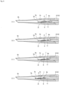
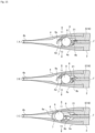
- the pushing member 5 moves forward by the engagement between the first screw portion 3b and the second screw portion 17a. At this time, the plunger portion 17 of the pushing member 5 moves straight in the central axis direction (X1 direction) of the injector main body 2 while engaging with the hollow portion of the injector main body 2. Further, the pushing member 5 moves as shown in FIGS. 6(A) to 6(D) in accordance with the rotation operation of the operation portion 3.
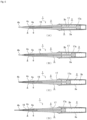
- FIG. 6(A) shows a stage in which the tip end part of the rod portion 18 of the pushing member 5 is advanced to the tip end part of the lens setting portion 6, and FIG. 6(B) shows a stage in which the tip end part of the rod portion 18 is advanced to the injection tube main body 4a of the injection tube 4. Further, FIG. 6(C) shows a stage in which the tip end part of the rod portion 18 is advanced to the nozzle portion 4b of the injection tube 4, and FIG. 7(D) shows a stage in which the tip end part of the rod portion 18 protrudes forward from the nozzle portion 4b of the injection tube 4.
- the tip end part of the rod portion 18 moves forward so as to push out the intraocular lens 7 from the lens setting portion 6.
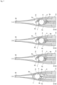
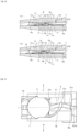
- the tip end part of the rod portion 18 pass the lens setting portion 6 mainly through four stages, by being guided by the guide slope 11. This state is shown in a plane sectional view of FIGS. 7(A) to 7(D) and a side sectional view of FIGS. 8(A) to 8(D) . Each stage will be described hereafter in detail.
- the first stage is the stage in which the tip end part of the rod portion 18 comes into contact with the support portion 9b as shown in FIGS. 7(A) and 8(A) .
- the first contact portion 18a at the tip end of the rod portion 18 comes into contact with the tip end side of the support portion 9b. Further, the tip end side of the support portion 9b is supported in a manner of riding onto the first contact portion 18a.
- the second stage is the stage of pushing the support portion 9b while the tip end part of the rod portion 18 comes into contact with the support portion 9b, as shown in FIGS. 7(B) and 8(B) .
- the tip end part of the rod portion 18 reaches the inclined portion 11a of the guide slope 11, an upward force is applied to the tip end part of the rod portion 18.
- the tip end part of the rod portion 18 is displaced upward due to an elastic deformation of the rod portion 18 itself. Therefore, the tip end part of the rod portion 18 moves forward so as to push the support portion 9b while being displaced upward along the inclined portion 11a of the guide slope 11.
- the support portion 9b is gradually bent. Further, the tip end side of the support portion 9b is gradually raised.
- the pair of support portions 9a and 9b are made of a material which is soft and easily elastically deformed, even if the support portion 9b is pushed in by the tip end part of the rod portion 18, the pushing force is absorbed by deformation of the support portion 9b. Therefore, even if the support portion 9b is pushed in by the tip end part of the rod portion 18, the position of the optical portion 8 hardly changes from an initial state.
- the third stage is the stage in which the tip end part of the rod portion 18 comes into contact with the optical portion 8, as shown in FIGS. 7 (C) and 8 (C) .
- the tip end part of the rod portion 18 comes into contact with the optical portion 8 by reaching the top portion 11b of the guide slope 11 and passing therethrough.
- the second contact portion 18b formed at the tip end part of the rod portion 18 comes into contact with the edge of the optical portion 8.
- the support portion 9b is further bent by the forward movement of the rod portion 18. Specifically, the support portion 9b as a whole is bent toward the optical portion 8 so as to form a substantially U-shape.
- the tip end side of the support portion 9b is properly raised before the tip end part of the rod portion 18 comes into contact with the optical portion 8. Therefore, the tip end part of the support portion 9b is less likely to catch on the edge of the optical portion 8, and in this situation, the tip end part of the support portion 9b rides onto the surface of the optical portion 8.
- the fourth stage is the stage in which the tip end part of the rod portion 18 pushes the entire intraocular lens 7 while coming into contact with the support portion 9b and the optical portion 8, as shown in FIGS. 7(D) and 8(D) .
- a downward force is exerted on the tip end part of the rod portion 18 by a reaction force due to the elastic deformation of the rod portion 18 itself, and therefore the inclined surface 18c of the rod portion 18 is pushed against the edge portion (the upper end of the step portion 11c) of the lower guide slope 11. Therefore, the tip end part of the rod portion 18 is gradually displaced downward in accordance with the inclination of the inclined surface 18c immediately after passing through the step portion 11c of the guide slope 11, and finally returns to an original height position.
- the intraocular lens 7 thus pushed out from the lens setting portion 6, is subsequently pushed by the rod portion 18 and moves forward in the injection tube 4.
- the optical portion 8 of the intraocular lens 7 is rounded from the left and right by the inner wall of the injection tube main body 4a having a tapered shape, and is finally folded so as to embrace the pair of support portions 9a, 9b.
- the support portion 9a is bent in conformity with the shape of the gradually narrowed space in the injection tube 4 (see FIG. 7 (D) ).
- the intraocular lens 7 thus folded is pushed out from the nozzle portion 4b of the injection tube 4 by the rod portion 18. At this time, by pushing out the intraocular lens 7 from the opening of the nozzle portion 4b in a state in which the nozzle portion 4b of the injection tube 4 is inserted into the incisional wound of the eyeball, the intraocular lens 7 can be injected into the eye.
- the tip end part of the rod portion 18 is guided by the guide mechanism so as to be displaced in a direction (vertical direction in this embodiment) intersecting the central axis of the injector main body 2, when the pushing member 5 moves in the central axis direction of the injector main body 2.
- the guide slope 11 in the injector main body 2 by forming the guide slope 11 in the injector main body 2 and displacing the tip end part of the rod portion 18 in the vertical direction along the guide slope 11, it is possible to raise the tip end side of the support portion 9b upward. Therefore, it is possible to create a situation in which the tip end part of the support portion 9b is easy to ride on the surface of the optical portion 8.
- the tip end part of the rod portion 18 pushes the support portion 9b while being displaced upward along the inclined portion 11a of the guide slope 11. Therefore, it is possible to perform the operation of bending the support portion 9b and the operation of raising the support portion 9b in parallel in a series of pushing operations by the pushing member 5.
- FIGS. 1 to 8 the abovementioned embodiment
- the other embodiments are referred to as a second embodiment, a third embodiment and the like, respectively.
- the same reference numerals are given to the same parts as those of the embodiment (the first embodiment) described above.
- the structure of the guide mechanism for guiding the movement of the pushing member 5 is different from that of the abovementioned first embodiment.
- the guide slope 11 is formed on the lens setting portion 6 of the injector body 2, and the guide mechanism is constituted by this guide slope 11.
- guide slopes are respectively provided on the upper side and the lower side of a moving path of the pushing member 5, and the guide mechanism is constituted by these guide slopes.
- the guide mechanism of the second embodiment includes a suppressing portion for suppressing a lateral shake of the tip end part of the pushing member 5.
- FIG. 9 is a sectional view showing an essential part of the intraocular lens injector according to the second embodiment of the present invention.
- FIG. 9 is a view obtained by vertically sectioning the essential part of the intraocular lens injector on the central axis J ( FIG. 1 ), wherein a left direction corresponds to the X1 direction, a right direction corresponds to the X2 direction, an upward direction corresponds to the Z1 direction, and a downward direction corresponds to the Z2 direction in the figure.
- the guide mechanism for guiding the movement of the pushing member 5 is constituted by the lower guide slope 11 and the upper guide slope 12.
- the lower guide slope 11 is constituted by the inclined portion 11a, the top portion 11b and the step portion 11c.
- the upper guide slope 12 is constituted by the inclined portion 12a.
- the lower guide slope 11 is formed on the lens setting portion 6 of the injector main body 2, and the upper guide slope 12 is formed on the inner wall of the injection tube 4.
- the inclined portion 12a of the upper guide slope 12 is disposed on the downstream side of the inclined portion 11a of the lower guide slope 11.
- the lower guide slope 11 displaces the tip end part of the rod portion 18 of the pushing member 5 upward using the inclined portion 11a
- the upper guide slope 12 displaces the tip end part of the rod portion 18 downward using the inclined portion 12a. Therefore, the inclined portion 11a of the lower guide slope 11 is inclined obliquely upward from the upstream side toward the downstream side in the moving direction (X1 direction) of the pushing member 5, and the inclined portion 12a of the upper guide slope 12 is inclined obliquely downward from the upstream side to the downstream side in the moving direction (X1 direction) of the pushing member 5.
- grooves 13, 14 are formed in pairs at upper and lower positions on the lens setting portion 6 of the injector main body 2, and the upper wall portion inside of the insertion tube 4 opposed to the lens setting portion 6.
- the groves 13 and 14 constitute a suppressing portion for suppressing the lateral shake of the tip end part of the pushing member 5 when the pushing member 5 moves in the central axis direction of the injector main body 2.
- the term "lateral shake of the tip end part of the pushing member 5" refers to a situation that the tip end part of the rod portion 18 swings in the left-right direction when the pushing member 5 waiting behind the lens installing portion 6 is moved in the X1 direction by the rotation operation of the operation portion 3.
- the tip end part of the pushing member 5 swings horizontally, the tip end part of the rod portion 18 cannot be stably brought into contact with a target position of the intraocular lens 7.
- the groove 13 is formed on the lower side of the movement path of the rod portion 18, and the groove 14 is formed on the upper side of the movement path of the rod portion 18. Therefore, the groove 13 and the groove 14 are opposed to each other in a vertical direction interposing the movement path of the rod portion 18.
- the lower groove 13 is referred to as a lower groove 13
- the upper groove 14 is referred to as an upper groove 14.
- FIG. 10 is a view for explaining the structure of the lower groove and the upper groove
- (A) is a schematic view when the upper groove is viewed from the position of the central axis of the injector main body
- (B) is a schematic view when the lower groove is viewed from the position of the central axis of the injector main body
- (C) is a view showing a sectional structure of the upper groove at the position V 1 - V 1 of (A)
- (D) is a view showing a sectional structure of the lower groove at the position V 2 - V 2 of (B).
- the lower groove 13 and the upper groove 14 are formed so as to be engaged with the tip end part of the rod portion 18 of the pushing member 5 in order to suppress the lateral shake of the tip end part of the pushing member 5.
- the lower groove 13 is recessed downward and the upper groove 14 is recessed upward.
- a width W1 of the lower groove 13 is set corresponding to a width of the tip end part of the rod portion 18, and a width W2 of the upper groove 14 is also set corresponding to a width dimension of the tip end part of the rod portion 18.
- FIG. 9 shows a state before the operation portion 3 of the intraocular lens injector 1 is rotated, namely, shows an initial state. In this initial state, the tip end part of the rod portion 18 receives a downward force.
- This downward force can be generated, for example, by elastically deforming the rod portion 18 itself so as to press the tip end part of the rod portion 18 downward. This point is the same in the first embodiment as well. Further, in the initial state, the lower side of the tip end part of the rod portion 18 is engaged with the lower groove 13.
- a range S1 for forming the lower groove 13 is a range from a tip end 13a to a rear end 13b of the lower groove 13
- a range S2 for forming the upper groove 14 is a range from a tip end 14a to a rear end 14b of the upper groove 14.
- the lower guide slope 11 is included in the range S1 of the lower groove 13
- the upper guide slope 12 is included in the range S2 of the upper groove 14.
- the lower groove 13 and the upper groove 14 are formed linearly respectively along the central axis direction of the intraocular lens injector 1.
- the lower guide slope 11 is formed in the middle of the lower groove 13, and the upper guide slope 12 is formed in the middle of the upper groove 14.
- the tip end 13a of the lower groove 13 is disposed at substantially the same position as the tip end 14a of the upper groove 14, and the rear end 13b of the lower groove 13 is disposed at a position displaced rearward from the rear end 14b of the upper groove 14. Therefore, the range S1 of the lower groove 13 is wider (longer) than the range S2 of the upper groove 14. Further, in the portion where the lower guide slope 11 is formed, the lower groove 13 is partly interrupted by the protrusion of the lower guide slope 11. The upper groove 14 is continuously formed in the middle of the range S2 without interruption. A depth D1 of the lower groove 13 is substantially uniform throughout the range S1. However, in the vicinity of the tip 13a of the lower groove 13, the depth D1 of the lower groove 13 gradually becomes shallow.
- a depth D2 of the upper groove 14 is deeper on the upstream side than the downstream side of the upper side guide slope 12. Further, in the portion where the upper guide slope 12 is formed, the depth D2 of the upper groove 14 is continuously changed in accordance with the inclination of the inclined portion 12a.
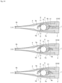
- FIG. 11(A) shows a stage in which the tip end part of the rod portion 18 of the pushing member 5 moves to a position in front of the lower guide slope 11
- FIG. 8(B) shows a stage in which the tip end part of the rod portion 18 moves to the inclined portion 11a of the lower guide slope 11
- FIG. 5(C) shows a stage in which the tip end part of the rod portion 18 is moved to the top portion 11b of the lower guide slope 11.
- FIG. 12(A) shows a stage in which the tip end part of the rod portion 18 moves forward of the lower guide slope 11
- FIG. 8(B) shows a stage in which the tip end part of the rod portion 18 moves forward of the upper guide slope 12.
- the tip end part of the rod portion 18 moves forward while being engaged with the lower groove 13, and during this movement, the first contact portion 18a of the rod portion 18 comes into contact with the support portion 9b of the intraocular lens 7. Thereby, the tip end side of the support portion 9b is supported in a manner of riding onto the first contact portion 18a. Further, the tip end part of the rod portion 18 also engages with the upper groove 14 in the middle of the movement.
- the tip end part of the rod portion 18 moves while displacing upward along the inclined portion 11a of the lower guide slope 11. At this time, the tip end part of the rod portion 18 moves so as to push the support portion 9b while displacing upward by the elastic deformation of the rod portion 18 itself. Thereby, the support portion 9b is gradually bent. Further, the tip end side of the support portion 9b is gradually raised.
- the tip end part of the rod portion 18 reaches the top portion 11b while displacing upward along the inclined portion 11a of the lower guide slope 11, and thereafter moves along the top portion 11b. At that time, the tip end part of the rod portion 18 moves while being engaged with the upper groove 14. Further, the second contact portion 18b of the rod portion 18 comes into contact with the edge of the optical portion 8 in the middle of or immediately after passing through the top portion 11b.
- the tip end part of the rod portion 18 moves while being displaced downward along the inclined portion 12a of the upper guide slope 12.
- the tip end part of the rod portion 18 moves while being engaged with the upper groove 14, and passes through the lower guide slope 11, and thereafter is engaged with the lower groove 13 again, and returns to an original height position.
- the tip end parts (18a, 18b) of the rod portion 18 push the entire intraocular lens 7 while being in contact with the support portion 9b and the optical portion 8. Therefore, the intraocular lens 7 further moves forward from the initial state.
- the guide slope 11 similar to that of the first embodiment is formed, and therefore even if the upper guide slope 12 is not formed, it is possible to displace the tip end part of the rod portion 18 downward by the same principle as in the first embodiment.
- a reaction force due to the elastic deformation of the rod portion 18 becomes weaker, and therefore there is a possibility that the operation of the rod portion 18 becomes unstable when the tip end part of the rod portion 18 rides onto the lower guide slope 11. Accordingly, in order to operate the rod portion 18 more stably, it is preferable to form the upper guide slope 12.
- the upper guide slope 12 When the upper guide slope 12 is formed as in the second embodiment, the upper end of the tip end part of the rod portion 18 approaches or comes into contact with the inclined portion 12a of the upper guide slope 12, immediately after the tip end part of the rod portion 18 passes through the step portion 11c of the lower guide slope 11. Therefore, the tip end part of the rod portion 18 is forcibly displaced downward along the inclined portion 12a of the upper guide slope 12. Accordingly, the displacement operation of the rod portion 18 becomes more stable.
- the tip end part of the rod portion 18 moves while being engaged with both the lower groove 13 and the upper groove 14. At this time, the tip end parts (18a, 18b) of the rod portion 18 further push the entire intraocular lens 7 while coming into contact with the support portion 9b and the optical portion 8.
- the tip end part of the rod portion 18 moves further forward while being engaged with both the lower groove 13 and the upper groove 14.
- the tip end part of the rod portion 18 disengages from the lower groove 13 at the stage of passing through the distal end 13a of the lower groove 13, and disengages from the upper groove 14 at the stage of passing through the tip end 14a of the upper groove 14. Therefore, the tip end part of the rod portion 18 moves while being engaged with both the lower groove 13 and the upper groove 14 except when it passes through the portion of the lower guide slope 11. Further, the tip end part of the rod portion 18 moves while being engaged with the upper groove 14 when it passes through the portion of the lower guide slope 11. Accordingly, the end portion of the rod portion 18 is continuously suppressed from the lateral shake due to the engagement with at least one of the grooves 13, 14 until the end of the passage through the ranges S1, S2 of the grooves 13, 14.
- the guide mechanism for guiding the movement of the pushing member 5 is constituted by the lower guide slope 11 and the upper guide slope 12. Therefore, it is possible to more stably perform the operation of vertically displacing the tip end part of the rod portion 18 of the pushing member 5.
- the lateral shake of the tip end part of the rod portion 18 is suppressed by the upper and lower grooves 13 and 14 when the tip end part of the rod portion 18 of the pushing member 5 is displaced in the vertical direction. Therefore, the tip end part of the rod portion 18 can be advanced straight. Accordingly, it is possible to bring the tip end part of the rod portion 18 into stable contact with the target position of the intraocular lens 7.
- the lower groove 13 and the upper groove 14 are formed in order to suppress the lateral shake of the tip end part of the pushing member 5.
- a structure other than the groove may be adopted as long as it exhibits the same function.
- the one-piece type intraocular lens 7 is made of a very soft material, and therefore when the support portion 9b is pushed in by the rod portion 18, there is a possibility that the shape of the support portion 9b is largely collapsed because the support portion 9b does not bend into a shape as expected by design. When such a phenomenon occurs, even if the support portion 9b is pushed by the rod portion 18, the tip end part of the support portion 9b can not be placed on the surface of the optical portion 8 as specified.
- the intraocular lens injector 1 suitable for handling the one-piece type intraocular lens 7 in which the entire intraocular lens 7 is made of a soft material.
- the intraocular lens injector 1 according to the third embodiment of the present invention can also be applied to a case of handling intraocular lenses other than the one-piece type.
- the structure of the lens setting portion 6 of the injector main body 2 is different, compared to the first embodiment described above.
- the structure of the lens setting portion 6 will be described hereafter in detail with reference to FIG. 13 .
- a guide groove 21 is formed in the lens setting portion 6.
- the guide groove 21 constitutes a guide mechanism for guiding the movement of the tip end part of the pushing member 5, when the pushing member 5 moves in the central axis direction of the injector main body 2.
- the guide groove 21 is formed in such a manner that the upper surface of the lens setting portion 6 is recessed in a concave shape in front of a region where the optical portion 8 is disposed in the lens setting portion 6.
- the guide groove 21 is curved with respect to the central axis J when the lens setting portion 6 is viewed from above.
- the upstream side (the right side in the figure) of the guide groove 21 curves in the right direction Y1 so as to be away from the position of the central axis J
- the downstream side (the left side in the figure) of the guide groove 21 is curved in the left direction Y2 so as to approach the position of the central axis J.
- the tip end part of the rod portion 18 is engaged with the guide groove 21.
- the tip end part of the rod portion 18 is configured to move along the guide groove 21 while being engaged with the guide groove 21. Further, when the tip end part of the rod portion 18 moves along the guide groove 21, a starting end portion 21a of the guide groove 21 which is a starting side of the movement is located on the central axis J in the left-right direction, and an end point 21b of the guide groove 21 on the opposite side is also located on the central axis J in the left-right direction.
- the tip end part of the support portion 9b is disposed so as to block a movement path of the rod portion 18 moving along the guide groove 21, when the intraocular lens 7 is set on the lens setting portion 6. Further, the tip end part of the support portion 9b is disposed at an middle point 21c in a longitudinal direction of the guide groove 21. In the middle point 21c of the guide groove 21, a curved direction of the guide groove 21 is switched from the right direction Y1 to the left direction Y2, and the tip end part of the support portion 9b is disposed in this portion.
- the tip end part of the rod portion 18 moves as follows by being guided by the guide groove 21.
- the tip end part of the rod portion 18 starts to move from a starting point 21a of the guide groove 21 located on the central axis J (see FIG. 13 ).
- the tip end part of the rod portion 18 moves from the starting point 21a to the middle point 21c of the guide groove 21 (see FIG. 13 ) along the guide groove 21.
- the tip end part of the rod portion 18 moves (advances) while displacing to the right direction Y1, due to the elastic deformation of the rod portion 18 itself.
- the tip end part of the rod portion 18 comes into contact with the tip end part of the support portion 9b at a position where it reaches the middle point 21c of the guide groove 21 (in other words, at a position deviated from the position of the central axis J in the right direction Y1).
- the first contact portion 18a formed at the tip end part of the rod portion 18 comes into contact with the tip end part of the support portion 9b. Thereby, the tip end part of the support portion 9b is supported in a manner of riding onto the first contact portion 18a.
- the tip end part of the rod portion 18 pushes the support portion 9b while moving along the guide groove 21.
- the support portion 9b is gradually bent by the forward movement of the rod portion 18. Further, the tip end part of the rod portion 18 moves (forwards) while displacing in the left direction Y2 in accordance with the curve of the guide groove 21.
- the tip end part of the rod portion 18 comes into contact with the optical portion 8 when it reaches the end point 21b (see FIG. 13 ) of the guide groove 21 located on the central axis J.
- the tip end part of the rod portion 18 comes into contact with the optical portion 8 at the position of the central axis J passing through substantially the center of the optical portion 8.
- the second contact portion 18b formed at the tip end part of the rod portion 18 comes into contact with the edge of the optical portion 8.
- the support portion 9b is further bent by the forward movement of the rod portion 18 along the guide groove 21. Specifically, the support portion 9b as a whole is bent toward the optical portion 8 so as to form a substantially U-shape.
- the tip end part of the rod portion 18 pushes the entire intraocular lens 7 while being in contact with the support portion 9b and the optical portion 8. In this stage, the tip end part of the rod portion 18 has passed through the guide groove 21. Therefore, the tip end part of the rod portion 18 moves straight along the central axis J.
- the description is omitted since it is the same as the first embodiment described above.
- the tip end part of the rod portion 18 is guided by the guide mechanism so as to be displaced in a direction crossing the central axis of the injector main body 2 (in the left-right direction in this embodiment).
- the position where the tip end part of the rod portion 18 comes into contact with the support portion 9b is positioned closer to the middle point in the longitudinal direction of the support portion 9b, as compared with the third embodiment.
- a risk that the tip end side of the support portion 9b is bent in a direction different from an expected direction by design is increased when the support portion 9b is pushed in by the tip end part of the rod portion 18.
- an expected direction by design typically the opposite direction
- the tip end part of the rod portion 18 is brought into contact with the tip end part of the support portion 9b at a position deviated in the right direction Y1 from the position of the central axis J, and thereafter the tip end part of the rod portion 18 is displaced in the left direction Y2 and is brought into contact with the optical portion 8 at the position of the central axis J. Therefore, the tip end side of the support portion 9b can be bent in the shape as expected by design when the support portion 9b is pushed in by the tip end part of the rod portion 18. Accordingly, the support portion 9b can be bent into a shape as expected. As a result, it is possible to reliably place the tip end part of the support portion 9b on the surface of the optical portion 8.
- the guide groove 21 in the injector main body 2 by forming the guide groove 21 in the injector main body 2 and displacing the tip end part of the rod portion 18 in the left-right direction along the guide groove 21, it is possible to suppress the shape collapse of the support portion 9b. Thereby, it is possible to bend the tip end side of the support portion 9b into a shape as expected and place the tip end part of the support portion 9b on the surface of the optical portion 8.
- the structure of the injector main body 2 and the injection tube 4 are different, as compared to the abovementioned first embodiment.
- a comparative embodiment of the present invention will be described, and thereafter the fourth embodiment of the present invention will be described.
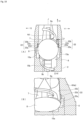
- FIG. 16 shows an internal structure of a joint portion between the injector main body and an injection tube as an essential part of the intraocular lens injector according to a comparative embodiment of the present invention
- (A) is a view of the internal structure of the joint portion viewed from above
- (B) is a perspective view of the internal structure of the joint portion viewed from backside.
- Edge portions 15a, 15b for positioning the intraocular lens 7 placed thereon are formed in the lens setting portion 6 of the injector main body 2.
- the edge portion 15a is formed in a shape conforming to an outer shape of the optical portion 8
- the edge portion 15b is formed in a shape conforming to an outer shape of the support portion 9b.
- a step is provided on each of the edge portions 15a and 15b, and positioning of the intraocular lens 7 can be performed by using this step difference. Namely, in the lens setting portion 6, the optical portion 8 is disposed along the edge portion 15a, and the support portion 9b is disposed along the edge portion 15b, to thereby determine a setting position (hereinafter referred to as "an initial position") of the intraocular lens 7 in an initial state.
- a position of the optical portion 8 at the time of setting the intraocular lens 7 at the initial position is a position where the optical portion 8 starts moving when the intraocular lens 7 is pushed out by the pushing member 5. Therefore, the movement start position of the optical portion 8 in the lens setting portion 6 is set using the edge portion 15a.
- a pair of right and left side wall guides 22, 22 are formed from the lens setting portion 6 to the inside of the injection tube 4 in the central axis direction of the intraocular lens injector 1.
- the pair of side wall guides 22 have guide surfaces 22a and 22b respectively that regulate the position in the right and left direction of the optical portion 8 by bringing the optical portion 8 close to or in contact with the left and right edges of the optical portion 8.
- One guide surface 22a is formed in the lens setting portion 6 and the other guide surface 22b is formed inside of the injection tube 4.
- one guide surface 22a is referred to as a first guide surface 22a
- the other guide surface 22b is referred to as a second guide surface 22b.
- the first guide surface 22a is formed on the lens setting portion 6 so as to be smoothly connected to the edge portion 15a.
- the first guide surface 22a is formed straight along the central axis J of the intraocular lens injector 1.
- the second guide surface 22b is formed on the side wall portion of the injection tube 4 so as to smoothly connect to the first guide surface 22a.
- the second guide surface 22b has an inclination with respect to the central axis J of the intraocular lens injector 1.
- the second guide surface 22b is gradually inclined inward (toward the central axis J of the intraocular lens injector 1) from a joint portion 22c between the first guide surface 22a and the second guide surface 22b.
- the distance is equal to or slightly larger than an outer diameter of the optical portion 8.
- the diameter is gradually decreased from the joint portion 22c with the first guide surface 22a toward the nozzle portion 4b ( FIG. 1 ) of the injection tube 4.
- the intraocular lens 7 set on the lens setting portion 6 when the intraocular lens 7 set on the lens setting portion 6, is pushed out by the rod portion 18 of the pushing member 5, the intraocular lens 7 starts moving from the initial position.
- the optical portion 8 moves forward (in the X1 direction) while being guided by the left and right first guide surfaces 22a.
- the left and right edges of the optical portion 8 reach the joint portion 22c between the first guide surface 22a and the second guide surface 22b.
- the first guide surface 22a and the second guide surface 22b are smoothly connected. Therefore, the optical portion 8 moves forward without being caught by the joint portion 22c.
- the second guide surface 22b is slightly outwardly disposed as compared with the first guide surface 22a so that the optical portion 8 is not caught by the joint portion 22c.
- FIG. 17 in order to easily understand how much the intraocular lens 7 has moved from the initial position shown in FIG. 16 , the shape of the rear support portion 9b is shown in the same manner as in FIG. 16 . However, actually the support portion 9b is pushed by the rod portion 18 and set in a bent state.
- the optical portion 8 moves further forward while being guided by the left and right second guide surfaces 22b.
- the distance between the left and right second guide surfaces 22b is gradually decreased toward the front, and accordingly, the space inside of the injection tube 4 is also gradually narrowed. Therefore, when the intraocular lens 7 is pushed out by the rod portion 18, the optical portion 8 is gradually bent while being guided by the left and right second guide surfaces 22b, and ultimately it is rounded small and folded.
- the first guide surface 22a and the second guide surface 22b of each side wall guide 22 are smoothly connected. Therefore, the optical portion 8 of the intraocular lens 7 moves along the first guide surface 22a and the second guide surface 22b without stopping at the joint portion 22c. In such a case, depending on the physical characteristics of the intraocular lens 7, there is a possibility that the following troubles occurs.
- the pair of support portions 9a, 9b have appropriate flexural rigidity to support the optical portion 8 in the eye. Therefore, depending on the intensity of the flexural rigidity of each of the support portions 9a, 9b, there is a possibility that the optical portion 8 starts to move in a state in which the bending deformation of the support portion 9b is insufficient, namely, at a timing earlier than expected when the support portion 9b is pushed in by the first contact portion 18a of the rod portion 18. In such a case, when the first guide surface 22a and the second guide surface 22b are smoothly connected as in the comparative embodiment, there is a possibility that the optical portion 8 is pushed forward with no riding of the tip end part of the support portion 9b onto the surface of the optical portion 8.
- the tip end part of the support portion 9b is easily caught on the edge of the optical portion 8.
- a pair of right and left recessed grooves for limiting a vertical displacement amount of the optical portion 8 is formed in the lens setting portion 6. Then in the initial state, the left and right outer peripheral parts of the optical portion 8 are disposed in the corresponding recessed grooves, thereby restricting the movement of the optical portion 8 in the vertical direction.
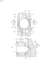
- FIG. 18 shows the internal structure of the joint portion between the injector main body and the injection tube as the essential part of the intraocular lens injector according to a fourth embodiment of the present invention, and (A) is a view of the internal structure of the joint portion viewed from above, and (B) is a perspective view of the internal structure of the joint portion viewed from the backside.
- the fourth embodiment is intended to solve the problem which may occur in the above comparative embodiment.
- the difference between the fourth embodiment and the comparative embodiment lies in the structure of the pair of side wall guides 22, 22.
- the first guide surface 22a and the second guide surface 22b of each side wall guide 22 are smoothly connected.
- the first guide surface 22a and the second guide surface 22b are not connected smoothly but the protrusion 22d is formed on the joint portion 22c.
- the protrusion 22d temporarily stops the optical portion 8 of the intraocular lens 7 pushed out by the pushing member 5.
- the protrusion 22d is formed at the joint portion 22c so that the second guide surface 22b protrudes inward from the first guide surface 22a (a side close to the central axis J of the intraocular lens injector 1) by a predetermined dimension Ly.
- the distance between the left and right side wall guides 22, 22 is shorter than the diameter of the optical portion 8 due to the protrusion of the protrusion 22d. Therefore, when the intraocular lens 7 set at the initial position of the lens setting portion 6 is pushed out by the pushing member 5, the left and right edges of the optical portion 8 are caught on the corresponding protrusion 22d.
- the protruding dimension Ly of the protrusion 22d corresponds to the amount of positional deviation in the left-right direction between the first guide surface 22a and the second guide surface 22b at the joint portion 22c, and it is preferably 0.1 mm or more and 0.5 mm or less. Since the protrusion 22d exists on both the left and right sides, for example, when the protruding dimension of the protrusion 22d is set to 0.2 mm, the distance between the left and right side wall guides 22 and 22 is shortened to 0.4 mm in total (0.2 mm on each side).
- the protrusion 22d is disposed so that when the optical portion 8 is disposed at the movement start position, it does not contact the optical portion 8, and when the optical portion 8 moves from the movement start position by a predetermined amount M (see FIG. 19 (A) ), it comes into contact with the optical portion 8.
- the predetermined amount M is preferably 0.5 mm or more and 1.0 mm or less, and more preferably 0.6 mm or more and 0.8 mm or less.
- the predetermined amount M is set to be shorter than a moving distance of the optical portion 8 until the outer peripheral part of the optical portion 8 is disengaged from the left and right recessed grooves. Thereby, the optical portion 8 can be brought into contact with the protrusion 22d before the outer peripheral part of the optical portion 8 is disengaged from the recessed groove.
- the distance between the left and right side wall guides 22, 22 is as follows. First, in the portion where the first guide surface 22a is formed, the above distance is the same as or slightly larger than the outer diameter of the optical portion 8 in the same manner as in the abovementioned comparative embodiment. In contrast, in the portion where the second guide surface 22b is formed, the above distance is gradually decreased from the protrusion 22d formed in the connecting portion 22c toward the nozzle portion 4b of the injection tube 4.
- the intraocular lens 7 set on the lens setting portion 6 when the intraocular lens 7 set on the lens setting portion 6 is pushed forward by the rod portion 18 of the pushing member 5, the intraocular lens 7 starts moving from its initial position.
- the optical portion 8 moves forward (in the X1 direction) while being guided by the left and right first guide surfaces 22a.
- the left and right edges of the optical portion 8 reach the joint portion 22c between the first guide surface 22a and the second guide surface 22b.
- the protrusion 22d is formed on this joint portion 22c. Therefore, as shown in FIGS. 19(A) and 19(B) , the left and right edges of the optical portion 8 come into contact with and hooked on the corresponding protrusion 22d respectively, and the optical portion 8 is temporarily stopped by this hooking.
- the support portion 9b can be sufficiently bent at the tip end part of the rod portion 18 while the optical portion 8 is temporarily stopped so that the tip end part of the support portion 9b can be placed on the surface of the optical portion 8. Further, by temporarily stopping the optical portion 8 before the left and right outer peripheral parts of the optical portion 8 are disengaged from the recessed groove, the tip end part of the rod portion 18 can be brought into contact with the edge of the optical portion 8, while limiting the amount of displacement in the vertical direction (in particular, upward direction) of the optical section 8 by the recessed groove. Therefore, the tip end part of the support portion 9b can be placed on the surface of the optical portion 8 without being hooked on the edge of the optical portion 8.
- the optical portion 8 moves forward while being guided by the left and right second guide surfaces 22b.
- the distance between the left and right second guide surfaces 22b is gradually decreased toward the front, and accordingly, the space inside of the injection tube 4 is also gradually narrowed. Therefore, when the intraocular lens 7 is pushed out by the rod portion 18, the optical portion 8 is gradually bent while being guided by the left and right second guide surfaces 22b, and ultimately it is rounded small and folded. At that time, when the tip end part of the support portion 9b rides on the surface of the optical portion 8, the optical portion 8 is likely to bend in a direction to embrace the support portion 9b.
- the optical portion 8 is easily deformed to the side on which the support portion 9b is placed, whereas the optical portion 8 is hardly deformed on the opposite side. Therefore, even when the optical portion 8 starts to move at an earlier timing than expected, the direction in which the optical portion 8 is bent can be determined in one direction (the direction in which the support portion 9b is embraced).
- any structure may be adopted as long as the structure of the protrusion 22d is such that the optical portion 8 can be temporarily stopped.
- the protrusion 22d may be formed so as to form a right angle with respect to the first guide surface 22a as shown in FIG. 20(A) , or the protrusion 22d may be formed so as to form an obtuse angle with respect to the first guide surface 22a as shown in FIG. 20(B) , or the projecting portion 22d may be formed in a round shape from the first guide surface 22a to the second guide surface 22b as shown in FIGS. 20(C) and (D) .
- the protrusion 22d is formed at the joint portion 22c between the first guide surface 22a and the second guide surface 22b.
- the present invention is not limited thereto, and the protrusion 22d may be formed in the middle of the first guide surface 22a or in the middle of the second guide surface 22b for the same purpose as described above.
- the preload type intraocular lens injector 1 is given as an example.
- the present invention is not limited thereto, and the present invention may be applied to an intraocular lens injector of the type in which the user using the intraocular lens injector sets the intraocular lens each time.
- the pushing member 5 is moved forward by the rotating operation of the operation portion 3.
- the present invention is not limited thereto, and it is also acceptable to adopt a structure in which the pushing member is pushed directly using a finger.
- the rod portion 18 of the pushing member 5 is configured to be elastically deformable, and when the pushing member 5 is moved forward, the tip end part of the rod portion 18 is displaced in a predetermined direction (vertical direction, left-right direction) by the elastic deformation of the rod portion 18.
- the present invention is not limited thereto, and for example it is also acceptable to adopt a structure in which the plunger portion 17 and the rod portion 18 are connected to each other and the rod portion 18 is rotatably supported by the joint portion between the plunger portion 17 and the rod portion 18.
- a pair of right and left recessed grooves are formed in the lens setting portion 6.
- the other structure may be acceptable.
- the pressing portions may be disposed above the right and left outer peripheral parts of the optical portion 8 interposing an appropriate gap.
- FIGS. 9 to 12 the following structure is adopted for your reference: a pressing portion 16 is formed inside of the injection tube 4 and the vertical displacement amount of the optical portion 8 is limited by the pressing portion 16.
- the abovementioned first embodiment and the second embodiment adopt a structure in which the tip end portion of the rod portion 18 is displaced in the vertical direction
- the third embodiment adopt a structure in which the tip end portion of the rod portion 18 is displaced in the left-right direction.
- the present invention is not limited thereto, and for example it is also acceptable to adopt a structure in which the tip end portion of the rod portion 18 is displaced in both the vertical direction and the left-right direction by appropriately combining the above embodiments. By adopting this structure, it is possible to more surely place the tip end portion of the support portion 9b on the surface of the optical portion 8.
- the guide groove 21 is curved in the right direction Y1 at a part from the starting point 21a to the middle point 21c of the guide groove 21.
- the present invention is not limited thereto, and the starting point 21a of the guide groove 21 may be disposed deviated in the rightward direction Y1 from the central axis J, and a part extending from the starting point 21a to the middle point 21c may be formed straight along the central axis J.
- the tip end part of the rod portion 18 moves straight through a part from the starting point 21a to the middle point 21c of the guide groove 21, and moves through a part from the middle point 21c to the end point 21b of the guide groove 21 while displacing in the left direction Y2.
Claims (14)
- Injecteur de lentille intraoculaire configuré pour injecter une lentille intraoculaire (7) ayant une partie optique (8) avec un bord périphérique et des parties supérieures (9a, 9b) s'étendant à partir de la partie optique (8) dans un œil, comprenant :un corps principal d'injecteur (2) ayant une partie de placement de lentille (6) sur laquelle la lentille intraoculaire (7) est placée ;un membre de poussée (5) configuré pour pousser la lentille intraoculaire (7) hors de la partie de placement de lentille (6) en se déplaçant dans une direction d'un axe central du corps principal d'injecteur (2) ; etun mécanisme de guidage (11) configuré pour guider le mouvement du membre de poussée (5) lorsque le membre de poussée (5) se déplace dans la direction de l'axe central du corps principal d'injecteur (2),dans lequel lorsque le membre de poussée (5) se déplace dans la direction de l'axe central du corps principal d'injecteur (2), une partie d'extrémité de pointe du membre de poussée (5) est configurée pour venir en contact avec l'une des parties de support (9a, 9b) de la lentille intraoculaire (7), et est configurée pour ensuite venir en contact avec la partie optique (8) tout en poussant la portion de support (9b) contactée, etle mécanisme de guidage (11) est configuré pour guider le mouvement du membre de poussée (5) de façon à ce que la partie d'extrémité de pointe du membre de poussée (5) soit déplacée par le mécanisme de guidage (11) dans une direction coupant l'axe central du corps principal d'injecteur (2) tandis que la partie d'extrémité de pointe du membre de poussée (5) pousse la portion de support (9b) contactée, etla partie d'extrémité de pointe du membre de poussée (5) est configurée pour pousser une partie de la portion de support (9b) contactée.
- Injecteur de lentille intraoculaire selon la revendication 1, dans lequel le mécanisme de guidage (11) inclut une pente de guidage (11) configurée pour guider le mouvement du membre de poussée (5), et configuré pour déplacer la partie d'extrémité de pointe du membre de poussée (5) dans une direction verticale le long de la pente de guidage (11).
- Injecteur de lentille intraoculaire selon la revendication 2, dans lequel le mécanisme de guidage (11) est configuré pour guider le mouvement du membre de poussée (5) de façon à ce que la partie d'extrémité de pointe du membre de poussée (5) pousse la portion de support (9b) contactée lors du déplacement vers le haut.
- Injecteur de lentille intraoculaire selon la revendication 2 ou 3, dans lequel le mécanisme de guidage (11) inclut :une pente de guidage (11) inférieure ayant une partie inclinée (11a) inclinée de manière oblique vers le haut à partir d'un côté amont vers un côté aval dans une direction de déplacement du membre de poussée (5) ; etune pente de guidage (12) supérieure ayant une partie inclinée (12a) inclinée de manière oblique vers le bas depuis le côté amont vers le côté aval dans la direction de mouvement du membre de poussée (5).
- Injecteur de lentille intraoculaire selon l'une quelconque des revendications 2 à 4, dans lequel le mécanisme de guidage (11) inclut une partie de retenue (13, 14) configurée pour supprimer une secousse latérale de la partie d'extrémité de pointe du membre de poussée (5) qui se déplace dans la direction de l'axe central du corps principal d'injecteur (2).
- Injecteur de lentille intraoculaire selon la revendication 1, dans lequel le mécanisme de guidage (11) a une rainure de guidage (21) pour guider le mouvement du membre de poussée (5), et la partie d'extrémité de pointe du membre de poussée (5) est déplacée dans une direction gauche-droite le long de la rainure de guidage (21).
- Injecteur de lentille intraoculaire selon la revendication 6, dans lequel le mécanisme de guidage (11) est configuré pour guider le mouvement du membre de poussée (5) de façon à ce que la partie d'extrémité de pointe du membre de poussée (5) vienne en contact avec la partie d'extrémité de pointe de la portion de support (9b) contactée à une position décalée de l'axe central du corps principal d'injecteur (2) dans une des directions gauche et droite, et ensuite la partie d'extrémité de pointe du membre de poussée (5) est déplacée vers l'autre côté dans la direction gauche-droite et vient en contact avec la partie optique (8) sur la position de l'axe central du corps principal d'injecteur (2) .
- Injecteur de lentille intraoculaire selon l'une quelconque des revendications 1 à 7, comprenant en outre :une paire de guides de paroi gauche et droite (22) qui guident le mouvement de la partie optique (8) de la lentille intraoculaire (7) poussée hors de la partie de placement de lentille (6) par le membre de poussée (5),dans lequel la paire de guides de paroi gauche et droite (22) a une surface de guidage (22a, 22b) pour guider la partie optique (8) de la lentille intraoculaire (7) poussée hors de la partie de placement de lentille (6) par le membre de poussée (5), et a une saillie (22d) pour arrêter temporairement la partie optique (8) se déplaçant le long de la surface de guidage (22a, 22b).
- Injecteur de lentille intraoculaire selon la revendication 8, dans lequel une position de départ de mouvement à laquelle la partie optique (8) de la lentille intraoculaire (7) commence de se déplacer est réglée dans la partie de placement de lentille (6), et
la saillie (22d) est disposée de façon à venir en contact avec la partie optique (8) lorsque la partie optique (8) est déplacée d'une quantité prédéterminée depuis la position de départ de mouvement. - Injecteur de lentille intraoculaire selon la revendication 9, dans lequel la quantité prédéterminée est de 0,5 mm ou plus et 1,0 mm ou moins.
- Injecteur de lentille intraoculaire selon l'une quelconque des revendications 8 à 10, dans lequel une dimension saillante de la saillie (22d) est de 0,1 mm ou plus et 0,5 mm ou moins.
- Injecteur de lentille intraoculaire selon l'une quelconque des revendications 1 à 11, dans lequel la lentille intraoculaire (7) est un type pré-chargée dans lequel la lentille intraoculaire (7) est pré-placée sur la partie de placement de lentille (6).
- Injecteur de lentille intraoculaire selon l'une quelconque des revendications 1 à 12, dans lequel la lentille intraoculaire (7) est placée sur la partie de placement de lentille (6) dans un état non-chargé.
- Injecteur de lentille intraoculaire selon l'une quelconque des revendications 1 à 13, dans lequella partie optique (8) de la lentille intraoculaire (7) a un bord périphérique ; et dans lequella partie d'extrémité de pointe du membre de poussée (5) fait se déplacer la partie d'extrémité de pointe du portion de support (9b) contacté sur le bord périphérique de la partie optique (8) et vient ensuite en contact avec la partie optique (8) tout en poussant la portion de support (9b) contactée.
Applications Claiming Priority (2)
| Application Number | Priority Date | Filing Date | Title |
|---|---|---|---|
| JP2015182568 | 2015-09-16 | ||
| PCT/JP2016/077327 WO2017047714A1 (fr) | 2015-09-16 | 2016-09-15 | Outil d'insertion de lentille intraoculaire |
Publications (4)
| Publication Number | Publication Date |
|---|---|
| EP3351212A1 EP3351212A1 (fr) | 2018-07-25 |
| EP3351212A4 EP3351212A4 (fr) | 2019-06-12 |
| EP3351212B1 EP3351212B1 (fr) | 2020-08-05 |
| EP3351212B2 true EP3351212B2 (fr) | 2023-08-23 |
Family
ID=58288996
Family Applications (1)
| Application Number | Title | Priority Date | Filing Date |
|---|---|---|---|
| EP16846585.4A Active EP3351212B2 (fr) | 2015-09-16 | 2016-09-15 | Outil d'insertion de lentille intraoculaire |
Country Status (8)
| Country | Link |
|---|---|
| US (1) | US10849738B2 (fr) |
| EP (1) | EP3351212B2 (fr) |
| JP (1) | JPWO2017047714A1 (fr) |
| KR (1) | KR20180056634A (fr) |
| CN (1) | CN107920891A (fr) |
| AU (1) | AU2016324545A1 (fr) |
| SG (1) | SG11201801775TA (fr) |
| WO (1) | WO2017047714A1 (fr) |
Families Citing this family (7)
| Publication number | Priority date | Publication date | Assignee | Title |
|---|---|---|---|---|
| EP2161005B1 (fr) | 2007-05-30 | 2016-12-28 | Hoya Corporation | Outil utilisé pour l'insertion d'une lentille intraoculaire |
| JP5254669B2 (ja) | 2008-06-05 | 2013-08-07 | Hoya株式会社 | 眼内レンズ挿入器具及びカートリッジ |
| JP6276619B2 (ja) | 2014-03-19 | 2018-02-07 | Hoya株式会社 | 眼内レンズ挿入器および眼内レンズ挿入装置 |
| JP6646987B2 (ja) | 2015-09-16 | 2020-02-14 | Hoya株式会社 | 眼内レンズ挿入器具 |
| KR102431211B1 (ko) | 2016-06-28 | 2022-08-09 | 호야 가부시키가이샤 | 안내 렌즈 삽입기 |
| CN108272535B (zh) * | 2018-03-23 | 2020-05-15 | 魏捷 | 一种眼科用人工晶状体取放装置 |
| WO2020151021A1 (fr) | 2019-01-25 | 2020-07-30 | 爱博诺德(北京)医疗科技股份有限公司 | Dispositif d'implant de lentille intraoculaire et appareil d'implant de lentille intraoculaire pré-chargé |
Family Cites Families (250)
| Publication number | Priority date | Publication date | Assignee | Title |
|---|---|---|---|---|
| US2761446A (en) | 1955-03-30 | 1956-09-04 | Chemical Specialties Co Inc | Implanter and cartridge |
| GB999506A (en) | 1960-11-02 | 1965-07-28 | Engis Ltd | Improvements in syringes for dispensing paste or the like |
| US4205747A (en) | 1978-09-05 | 1980-06-03 | Cilco, Inc. | Lens storage device |
| US4269307A (en) | 1979-08-09 | 1981-05-26 | Iolab Corporation | Intraocular lens storage assembly |
| US4423809A (en) | 1982-02-05 | 1984-01-03 | Staar Surgical Company, Inc. | Packaging system for intraocular lens structures |
| US4702244A (en) | 1982-02-05 | 1987-10-27 | Staar Surgical Company | Surgical device for implantation of a deformable intraocular lens |
| US4573998A (en) | 1982-02-05 | 1986-03-04 | Staar Surgical Co. | Methods for implantation of deformable intraocular lenses |
| US4608049A (en) | 1982-06-28 | 1986-08-26 | Kelman Charles D | Intraocular lens and method of inserting an intraocular lens into an eye |
| US4634423A (en) | 1984-04-30 | 1987-01-06 | Bailey Jr Paul F | Ophthalmological method and instrument for implantation of posterior chamber intraocular lens |
| US4787904A (en) | 1984-07-06 | 1988-11-29 | Severin Sanford L | Hydrophillic intraocular lens |
| US4699140A (en) | 1985-07-10 | 1987-10-13 | Iolab Corporation | Instrument for inserting an intraocular lens |
| US4681102A (en) | 1985-09-11 | 1987-07-21 | Bartell Michael T | Apparatus and method for insertion of an intra-ocular lens |
| US4715373A (en) | 1985-09-27 | 1987-12-29 | Mazzocco Thomas R | Devices for implantation of deformable intraocular lens structures |
| US4750498A (en) | 1986-02-21 | 1988-06-14 | Coopervision, Inc. | Method and tool for inserting an intraocular lens |
| DE3610925C2 (de) | 1986-03-24 | 1994-11-03 | Michael Ulrich Prof D Dardenne | Vorrichtung zum Falten einer insbesondere mit zwei seitlichen Kunststoffhaptikplatten versehenen, implantierbaren Intraokularlinse und zum Einbringen der gefalteten Intraokularlinse in das Auge |
| US4697697A (en) | 1986-08-18 | 1987-10-06 | Coopervision, Inc. | Method and apparatus for packaging an intraocular lens |
| JPS63197453A (ja) | 1986-11-07 | 1988-08-16 | ザ・クーパー・カンパニー・インク | 圧縮性眼内レンズを眼に挿入する器具および方法 |
| US4919130A (en) | 1986-11-07 | 1990-04-24 | Nestle S.A. | Tool for inserting compressible intraocular lenses into the eye and method |
| US4747404A (en) | 1986-11-10 | 1988-05-31 | Kresge Eye Institute Of Wayne State University | Foldable intraocular lens inserter |
| US4763650A (en) | 1987-01-20 | 1988-08-16 | Hauser Stephen G | Instrument for inserting a deformable lens into the eye |
| US4810249A (en) | 1987-03-12 | 1989-03-07 | Habley Medical Technology Corp. | Linear and Vernier-type syringe |
| US4994028A (en) | 1987-03-18 | 1991-02-19 | Endocon, Inc. | Injector for inplanting multiple pellet medicaments |
| US4988352A (en) | 1987-03-26 | 1991-01-29 | Poley Brooks J | Method and apparatus for folding, freezing and implanting intraocular lens |
| US4819631A (en) | 1987-03-26 | 1989-04-11 | Poley Brooks J | Folded intraocular lens, method of implanting it, retainer, and apparatus for folding lens |
| US4769034A (en) | 1987-03-26 | 1988-09-06 | Poley Brooks J | Folded intraocular lens, method of implanting folded intraocular lens |
| US5176686A (en) | 1987-03-26 | 1993-01-05 | Poley Brooks J | Apparatus for packaging, folding, rigidifying and inserting an intraocular lens |
| US4781719A (en) | 1987-07-28 | 1988-11-01 | Kelman Charles D | Method of inserting an intraocular lens into an eye |
| US4759359A (en) | 1987-08-31 | 1988-07-26 | Allergan, Inc. | Lens implantation instrument |
| US4834094A (en) | 1987-10-07 | 1989-05-30 | Patton Medical Technologies, Inc. | "Canoe" apparatus for inserting intra-ocular lens into the eye |
| US4765329A (en) | 1987-10-19 | 1988-08-23 | Cumming, Redwitz & Wilson, Inc. | Intraocular lens insertion instrument |
| US4880000A (en) | 1987-12-15 | 1989-11-14 | Iolab Corporation | Lens insertion instrument |
| US4934363A (en) | 1987-12-15 | 1990-06-19 | Iolab Corporation | Lens insertion instrument |
| US4836201A (en) | 1988-03-24 | 1989-06-06 | Patton Medical Technologies, Inc. | "Envelope" apparatus for inserting intra-ocular lens into the eye |
| US4862885A (en) | 1988-05-25 | 1989-09-05 | Cumming J Stuart | Instrument for inserting a deformable intraocular lens into the eye |
| CA2000287A1 (fr) | 1988-10-07 | 1990-04-07 | David C. Buboltz | Instrument servant a introduire des lentilles intraoculaires |
| US5066297A (en) | 1989-01-23 | 1991-11-19 | Cumming J Stuart | Intraocular lens insertion device |
| US4976716A (en) | 1989-01-23 | 1990-12-11 | Cumming J Stuart | Intraocular lens insertion device |
| US4955889A (en) | 1989-02-06 | 1990-09-11 | Allergan, Inc. | Apparatus for inserting a lens into an eye and method for using same |
| US5098439A (en) | 1989-04-12 | 1992-03-24 | Allergan, Inc. | Small incision intraocular lens insertion apparatus |
| US5222972A (en) | 1989-04-12 | 1993-06-29 | Allergan, Inc. | Small incision intraocular lens insertion apparatus |
| US5171241A (en) | 1989-06-09 | 1992-12-15 | Ioptex Research Inc. | Device for folding an intraocular lens and holding it in the folded state |
| DE4030492C1 (fr) | 1990-09-26 | 1991-09-05 | Adatomed Pharmazeutische Und Medizintechnische Gesellschaft Mbh, 8000 Muenchen, De | |
| DE4039119C1 (fr) | 1990-12-07 | 1991-09-05 | Dieter Dr.Med. 8904 Friedberg De Klaas | |
| DE4108303C2 (de) | 1991-03-14 | 1993-11-04 | Adatomed Pharma & Med | Verfahren und vorrichtung zum einbringen einer gummielastischen intraokularlinse in ein implantationswerkzeug |
| DE4110278A1 (de) | 1991-03-28 | 1992-10-01 | Geuder Hans Gmbh | Augenchirurgisches instrument zum implantieren von hinterkammer-weichlinsen |
| US5123905A (en) | 1991-06-07 | 1992-06-23 | Kelman Charles D | Intraocular lens injector |
| JPH0779825B2 (ja) | 1991-06-13 | 1995-08-30 | キヤノンスター株式会社 | 眼内レンズの移植器具 |
| JPH0779826B2 (ja) | 1991-06-14 | 1995-08-30 | キヤノンスター株式会社 | 眼内レンズの移植器具 |
| US5259395A (en) | 1992-01-15 | 1993-11-09 | Siemens Pacesetter, Inc. | Pacemaker lead with extendable retractable lockable fixing helix |
| US5190552A (en) | 1992-02-04 | 1993-03-02 | Kelman Charles D | Slotted tube injector for an intraocular lens |
| US5571113A (en) | 1992-05-18 | 1996-11-05 | Henry H. McDonald | Surgical probe with tips for plastic lens implantation in the eye |
| US5395378A (en) | 1992-05-18 | 1995-03-07 | Henry H. McDonald | Eye implantable lens haptics insertion and twist apparatus |
| US5242450A (en) | 1992-05-18 | 1993-09-07 | Henry H. McDonald | Eye implantable lens haptics twist apparatus |
| US5304182A (en) | 1992-09-23 | 1994-04-19 | Kabi Pharmacia Ophthalmics, Inc. | Apparatus and method for curling and inserting flexible intraocular lenses |
| US5616148A (en) | 1992-09-30 | 1997-04-01 | Staar Surgical Company, Inc. | Transverse hinged deformable intraocular lens injecting apparatus |
| US6059791A (en) | 1992-09-30 | 2000-05-09 | Staar Surgical Company, Inc. | Deformable intraocular lens injection system, and method thereof |
| US6056757A (en) | 1992-09-30 | 2000-05-02 | Staar Surgical Company, Inc. | Implantation device with deformable nozzle tip for implanting a deformable intraocular lens |
| US5728102A (en) | 1992-09-30 | 1998-03-17 | Staar Surgical Company, Inc. | Disposable intraocular lens insertion system |
| US5860984A (en) | 1992-09-30 | 1999-01-19 | Staar Surgical Company, Inc. | Spring biased deformable intraocular injecting apparatus |
| US5807400A (en) | 1992-09-30 | 1998-09-15 | Staar Surgical Company, Inc. | Deformable intraocular lens insertion system |
| US6712848B1 (en) | 1992-09-30 | 2004-03-30 | Staar Surgical Company, Inc. | Deformable intraocular lens injecting apparatus with transverse hinged lens cartridge |
| US6022358A (en) | 1992-09-30 | 2000-02-08 | Staar Surgical Company, Inc. | Deformable intraocular lens injecting device |
| US5772666A (en) | 1992-09-30 | 1998-06-30 | Staar Surgical Company, Inc. | Deformable intraocular lens injecting apparatus with deformable tip plunger |
| US5620450A (en) | 1992-09-30 | 1997-04-15 | Staar Surgical Company, Inc. | Transverse hinged deformable intraocular lens injecting apparatus |
| US5499987A (en) | 1992-09-30 | 1996-03-19 | Staar Surgical Company | Deformable intraocular lens cartridge |
| US5941886A (en) | 1992-09-30 | 1999-08-24 | Staar Surgical Company, Inc. | Hingeless lens cartridges for insertion of deformable intraocular lens |
| US6506195B2 (en) | 1992-09-30 | 2003-01-14 | Staar Surgical Company, Inc. | Deformable intraocular lens insertion system |
| US6001107A (en) | 1992-09-30 | 1999-12-14 | Staar Surgical Company, Inc. | Deformable intraocular lens injecting apparatus |
| US5876440A (en) | 1992-09-30 | 1999-03-02 | Staar Surgical Company, Inc. | Methods of implantation of deformable intraocular lens |
| US6406481B2 (en) | 1992-09-30 | 2002-06-18 | Starr Surgical Company, Inc. | Method preloading a deformable intraocular lens into injecting apparatus for storage and/or shipment |
| DE69331807T2 (de) | 1992-09-30 | 2002-09-26 | Vladimir Feingold | Intraokulares linsen-einführungssystem |
| US5928245A (en) | 1992-09-30 | 1999-07-27 | Staar Surgical Company, Inc. | Deformable intraocular lens injecting apparatus with transverse hinged lens cartridge |
| US5281227A (en) | 1992-11-09 | 1994-01-25 | Allergan, Inc. | Lens case with IOL folding device |
| US5275604A (en) | 1992-12-03 | 1994-01-04 | Kabi Pharmacia Ophthalmics, Inc. | Contoured duct apparatus and method for insertion of flexible intraocular lens |
| US5653715A (en) | 1993-03-09 | 1997-08-05 | Chiron Vision Corporation | Apparatus for preparing an intraocular lens for insertion |
| US5468246A (en) | 1993-07-02 | 1995-11-21 | Iovision, Inc. | Intraocular lens injector |
| US5425734A (en) | 1993-07-02 | 1995-06-20 | Iovision, Inc. | Intraocular lens injector |
| JP3459664B2 (ja) | 1993-07-15 | 2003-10-20 | キヤノンスター株式会社 | 変形可能な眼内レンズの挿入器具 |
| SE9303568D0 (sv) | 1993-10-29 | 1993-10-29 | Kabi Pharmacia Ab | Improvements in injection devices |
| US5584304A (en) | 1993-11-18 | 1996-12-17 | Allergan, Inc. | Method of inserting an IOL using a forceps inside a folding tube |
| WO1995013766A1 (fr) | 1993-11-18 | 1995-05-26 | Allergan, Inc. | Appareil servant a implanter dans l´×il des lentilles souples |
| US5702402A (en) | 1994-04-29 | 1997-12-30 | Allergal | Method and apparatus for folding of intraocular lens |
| US5582613A (en) | 1993-11-18 | 1996-12-10 | Allergan | Apparatus and methods for controlled insertion of intraocular lenses |
| WO1995021594A1 (fr) | 1994-02-09 | 1995-08-17 | Kabi Pharmacia Ophthalmics, Inc. | Implantation rapide de lentilles optiques deformables |
| US6174315B1 (en) | 1994-02-15 | 2001-01-16 | Staar Surgical Company, Inc. | Spring biased deformable intraocular injecting apparatus |
| US5578042A (en) | 1994-03-14 | 1996-11-26 | Cumming; J. Stuart | Ophthalmic kit and method for lens insertion |
| US5645534A (en) | 1994-06-24 | 1997-07-08 | Becton Dickinson And Company | Time of last injection indicator for medication delivery pen |
| JP3412106B2 (ja) | 1994-07-07 | 2003-06-03 | キヤノンスター株式会社 | 変形可能な眼内レンズの挿入器具 |
| JP3412107B2 (ja) | 1994-07-18 | 2003-06-03 | キヤノンスター株式会社 | 変形可能な眼内レンズの挿入器具 |
| US5454818A (en) | 1994-07-26 | 1995-10-03 | Alcon Laboratories, Inc. | Intraocular lens folder |
| CA2173609C (fr) | 1994-08-05 | 2006-06-20 | Dennis Alexander Figueroa | Dispositif pour l'insertion d'une lentille intraoculaire souple |
| ATE245012T1 (de) | 1994-11-18 | 2003-08-15 | Vladimir Feingold | Einführungssystem für wegwerfbare intraokulare linsen |
| US5803925A (en) | 1995-01-17 | 1998-09-08 | Allergan | IOL insertion apparatus with covalently bonded lubricant |
| CN1185100A (zh) | 1995-03-14 | 1998-06-17 | 约翰·R·沃尔夫 | 柔性眼内晶状体注射系统 |
| US5643276A (en) | 1995-10-10 | 1997-07-01 | Allergan | Apparatus and method for providing desired rotational orientation to an intraocular lens |
| DE19544119A1 (de) | 1995-11-27 | 1997-05-28 | Wolfram Dr Wehner | Implantationswerkzeug zum Implantieren einer faltbaren, flexiblen Intraokularlinse |
| US5776138A (en) | 1996-01-26 | 1998-07-07 | Allergan | Apparatus and methods for IOL insertion |
| US5735858A (en) | 1996-01-26 | 1998-04-07 | Allergan | IOL insertion apparatus and method for using same |
| FR2749752B1 (fr) | 1996-06-17 | 1998-11-20 | Moria Sa | Dispositif de pliage et de maintien plie d'un implant intraoculaire souple |
| US6083230A (en) | 1997-07-30 | 2000-07-04 | Allergan | Method for making IOL insertion apparatus |
| US5716364A (en) | 1996-07-10 | 1998-02-10 | Allergan | IOL insertion apparatus and method for making and using same |
| US6283975B1 (en) | 1996-07-10 | 2001-09-04 | Allergan Sales, Inc. | IOL insertion apparatus and method for making and using same |
| US5876406A (en) | 1996-08-02 | 1999-03-02 | Staar Surgical Company, Inc. | Deformable intraocular lens injecting apparatus with transverse hinged lens cartridge |
| US5766181A (en) | 1996-08-02 | 1998-06-16 | Staar Surgical Company, Inc. | Spring biased deformable intraocular injecting apparatus |
| US5944725A (en) | 1996-09-26 | 1999-08-31 | Bausch & Lomb Surgical, Inc. | Method and apparatus for inserting a flexible membrane into an eye |
| US5810834A (en) | 1996-10-07 | 1998-09-22 | Chiron Vision Corporation | Tip formation for inserting a flexible membrane into an eye |
| JP3226813B2 (ja) | 1996-12-13 | 2001-11-05 | トリンプ・インターナショナル・ジャパン株式会社 | 女性用衣類 |
| US5947975A (en) | 1997-03-07 | 1999-09-07 | Canon Staar Co., Inc. | Inserting device for deformable intraocular lens |
| US5919197A (en) | 1997-05-05 | 1999-07-06 | Surgical Concepts, Inc. | Insertion of multiple folded lens into the eye |
| JP3779819B2 (ja) | 1997-08-11 | 2006-05-31 | キヤノンスター株式会社 | 眼内挿入用レンズの挿入器具 |
| US5921966A (en) | 1997-08-11 | 1999-07-13 | Becton Dickinson And Company | Medication delivery pen having an improved clutch assembly |
| US6605093B1 (en) | 1997-10-24 | 2003-08-12 | Tekia, Inc. | Device and method for use with an ophthalmologic insertor apparatus |
| US5947974A (en) | 1997-12-09 | 1999-09-07 | Allergan | Folding device and method for an intraocular lens |
| US6050999A (en) | 1997-12-18 | 2000-04-18 | Keravision, Inc. | Corneal implant introducer and method of use |
| US5921989A (en) | 1998-02-12 | 1999-07-13 | Allergan | Lens protector for intraocular lens inserter |
| US6497708B1 (en) | 1998-05-11 | 2002-12-24 | Medevec Licensing, B.V. | Intraocular lens insertion instrument |
| US6371960B2 (en) | 1998-05-19 | 2002-04-16 | Bausch & Lomb Surgical, Inc. | Device for inserting a flexible intraocular lens |
| US6143001A (en) | 1998-06-02 | 2000-11-07 | Alcon Laboratories, Inc. | Asymmetric intraocular lens injection cartridge |
| US6010510A (en) | 1998-06-02 | 2000-01-04 | Alcon Laboratories, Inc. | Plunger |
| US6447520B1 (en) | 2001-03-19 | 2002-09-10 | Advanced Medical Optics, Inc. | IOL insertion apparatus with IOL engagement structure and method for using same |
| DE19904220C2 (de) | 1999-02-03 | 2001-08-30 | Helmut Binder | Injektor zum Falten und Einbringen einer Intraokularlinse, und Behälter zum Lagern und Transportieren des Injektors |
| FR2789890B1 (fr) | 1999-02-22 | 2002-01-18 | Lab Contactologie Appl Lca | Dispositif pour l'injection d'une lentille intra-oculaire en matiere souple |
| US6129733A (en) | 1999-04-15 | 2000-10-10 | Allergan Sales, Inc. | Apparatus for holding intraocular lenses and injectors, and methods for using same |
| US6386357B1 (en) | 1999-07-12 | 2002-05-14 | Hoya Healthcare Corporation | Soft intraocular lens-folding device and storage case |
| US6248111B1 (en) | 1999-08-06 | 2001-06-19 | Allergan Sales, Inc. | IOL insertion apparatus and methods for using same |
| US6699285B2 (en) | 1999-09-24 | 2004-03-02 | Scieran Technologies, Inc. | Eye endoplant for the reattachment of a retina |
| JP3728155B2 (ja) | 1999-10-05 | 2005-12-21 | キヤノンスター株式会社 | 眼内挿入用レンズの挿入システム |
| JP3944555B2 (ja) | 1999-10-06 | 2007-07-11 | キヤノンスター株式会社 | 眼内挿入用レンズの挿入システム |
| US6387101B1 (en) | 1999-10-22 | 2002-05-14 | Staar Surgical Company, Inc. | Deformable intraocular lens injecting apparatus and method |
| US6312433B1 (en) | 1999-10-22 | 2001-11-06 | Staar Surgical Company, Inc. | Deformable intraocular lens injecting apparatus and method |
| US6251114B1 (en) | 1999-10-29 | 2001-06-26 | Allergan Sales, Inc. | Rotatable IOL insertion apparatus and method for using same |
| SE9904338D0 (sv) | 1999-11-30 | 1999-11-30 | Pharmacia & Upjohn Ab | Intraocular lens implanter |
| US6283976B1 (en) | 2000-05-05 | 2001-09-04 | Allergan Sales Inc. | Intraocular lens implanting instrument |
| GB0011507D0 (en) | 2000-05-13 | 2000-06-28 | Duckworth & Kent Ltd | Ophthalmic lens injectors |
| FR2814360B1 (fr) | 2000-09-28 | 2002-12-27 | Corneal Ind | Injecteur d'implant intraoculaire souple |
| US6500181B1 (en) | 2000-10-17 | 2002-12-31 | Valdemar Portney | Instrument for folding and inserting anterior chamber intraocular lenses |
| US6471708B2 (en) | 2000-12-21 | 2002-10-29 | Bausch & Lomb Incorporated | Intraocular lens and additive packaging system |
| US6899699B2 (en) | 2001-01-05 | 2005-05-31 | Novo Nordisk A/S | Automatic injection device with reset feature |
| US6540754B2 (en) | 2001-01-26 | 2003-04-01 | Advanced Medical Optics, Inc. | Apparatus and method for multiply folding and inserting an intraocular lens in an eye |
| US6554839B2 (en) | 2001-01-26 | 2003-04-29 | Advanced Medical Optics, Inc. | Stepped IOL insertion cartridge for inserting an intraocular lens in an eye |
| FR2822055B1 (fr) | 2001-03-16 | 2003-09-12 | Lab Contactologie Appl Lca | Injecteur pour lentille intraoculaire |
| JP4264704B2 (ja) | 2001-04-07 | 2009-05-20 | グローコス コーポレーション | 緑内障ステントおよび緑内障治療方法 |
| EP1391185B1 (fr) | 2001-05-25 | 2012-06-27 | Hoya Healthcare Corporation | Récipient de stockage ayant une fonction de pliage de lentilles intraoculaires souples |
| JP2002355268A (ja) | 2001-06-01 | 2002-12-10 | Nidek Co Ltd | 眼内レンズ挿入器具 |
| US6537283B2 (en) | 2001-08-17 | 2003-03-25 | Alcon, Inc. | Intraocular lens shipping case and injection cartridge |
| ATE442106T1 (de) | 2001-08-23 | 2009-09-15 | Meyer & Co Ag Anton | Vorrichtung zur einführung einer linse in ein auge |
| JP3861138B2 (ja) | 2001-09-04 | 2006-12-20 | キヤノンスター株式会社 | 眼内レンズの挿入器具 |
| US7037312B2 (en) | 2001-09-07 | 2006-05-02 | Canon-Staar Co., Inc. | Insertion device for deformable intraocular lens |
| US7798185B2 (en) | 2005-08-01 | 2010-09-21 | Medical Instill Technologies, Inc. | Dispenser and method for storing and dispensing sterile food product |
| US20030088253A1 (en) | 2001-11-07 | 2003-05-08 | Seil Randolph L | Dual action ophthalmic implant extractor |
| FR2833154B1 (fr) | 2001-12-12 | 2004-11-19 | Ioltechnologie Production | Cassette et injecteur de lentille intraoculaire souple et procede d'injection de telles lentilles |
| JP3791421B2 (ja) | 2002-01-23 | 2006-06-28 | キヤノンスター株式会社 | 眼内レンズの挿入器具 |
| US6723104B2 (en) | 2002-03-13 | 2004-04-20 | Advanced Medical Optics, Inc. | IOL insertion apparatus and method for using same |
| US6733507B2 (en) | 2002-04-12 | 2004-05-11 | Advanced Medical Optics, Inc. | Intraocular lens insertion apparatus |
| JP2003325569A (ja) | 2002-05-08 | 2003-11-18 | Canon Star Kk | 眼内挿入用レンズの挿入システム |
| JP2003325570A (ja) | 2002-05-08 | 2003-11-18 | Canon Star Kk | 眼内挿入用レンズの挿入システム |
| US7131976B2 (en) | 2002-05-08 | 2006-11-07 | Canon-Staar Co. Inc. | Insertion device for intraocular lens |
| JP2003325572A (ja) | 2002-05-08 | 2003-11-18 | Canon Star Kk | 眼内挿入用レンズの挿入システム |
| JP3876284B2 (ja) | 2002-05-08 | 2007-01-31 | キヤノンスター株式会社 | 眼内挿入用レンズの挿入器具 |
| US7014641B2 (en) | 2002-05-08 | 2006-03-21 | Canon-Staar Co., Inc. | Insertion device for intraocular lens |
| US6923815B2 (en) | 2002-05-14 | 2005-08-02 | Advanced Medical Optics, Inc. | Intraocular lens insertion apparatus |
| BR0312968A (pt) | 2002-07-26 | 2005-06-14 | Pharmacia Groningen Bv | Método e dispositivo para manipulação de uma lente intraocular |
| US20040186428A1 (en) | 2002-09-11 | 2004-09-23 | Utpal Ray | Auto-destructible syringe |
| US20040147938A1 (en) | 2002-09-25 | 2004-07-29 | Microsurgical Technology | System for IOL insertion |
| ES2305194T3 (es) | 2002-12-09 | 2008-11-01 | ANTON MEYER & CO. AG | Aguaj de embolo para un inyector de lentes intraocular. |
| US7074227B2 (en) | 2002-12-12 | 2006-07-11 | Valdemar Portney | IOL insertion tool with forceps |
| US20050033308A1 (en) | 2003-04-11 | 2005-02-10 | Callahan Wayne B. | Intraocular lens storage and insertion device and method of use thereof |
| US20060293694A1 (en) | 2003-05-27 | 2006-12-28 | Hoya Corporation | Injector |
| US7156854B2 (en) | 2003-05-28 | 2007-01-02 | Alcon, Inc. | Lens delivery system |
| US8403941B2 (en) | 2003-06-02 | 2013-03-26 | Abbott Medical Optics Inc. | Intraocular lens and cartridge packaging with lens-loading function |
| US7429263B2 (en) | 2003-08-28 | 2008-09-30 | Bausch & Lomb Incorporated | Preloaded IOL injector |
| US7422604B2 (en) | 2003-08-28 | 2008-09-09 | Bausch & Lomb Incorporated | Preloaded IOL injector |
| JP4590505B2 (ja) | 2003-10-01 | 2010-12-01 | スター・ジャパン株式会社 | 眼内レンズの挿入器具 |
| WO2005065592A1 (fr) | 2003-12-30 | 2005-07-21 | Bausch & Lomb Incorporated | Plongeur ameliore pour systeme d'insertion de lentille intra-oculaire |
| JP4707016B2 (ja) * | 2004-01-27 | 2011-06-22 | Hoya株式会社 | 眼内レンズ挿入装置及びそのカートリッジ |
| US7645300B2 (en) | 2004-02-02 | 2010-01-12 | Visiogen, Inc. | Injector for intraocular lens system |
| JP4749413B2 (ja) | 2004-03-02 | 2011-08-17 | アボット・メディカル・オプティクス・インコーポレイテッド | 眼内レンズを保管、装填および送達するためのデバイスおよび方法 |
| US7458976B2 (en) | 2005-03-02 | 2008-12-02 | Advanced Medical Optics, Inc. | Devices and methods for storing, loading, and delivering an intraocular lens |
| US7947049B2 (en) | 2004-03-31 | 2011-05-24 | Bausch & Lomb Incorporated | IOL injector |
| US20080097459A1 (en) | 2004-04-22 | 2008-04-24 | Advanced Vision Science, Inc. | Device For The Insertion Of Deformable Intra-Ocular Lenses |
| US20060085013A1 (en) | 2004-10-20 | 2006-04-20 | Vaclav Dusek | Intraocular lens inserter |
| ES2367787T3 (es) | 2004-11-30 | 2011-11-08 | BAUSCH & LOMB INCORPORATED | Émbolo de dos fases para inyector de lente intraocular. |
| WO2006070628A1 (fr) | 2004-12-27 | 2006-07-06 | Hoya Corporation | Dispositif d’implantation de lentille intraoculaire |
| JP4766442B2 (ja) | 2004-12-28 | 2011-09-07 | Hoya株式会社 | 眼内レンズ挿入用器具 |
| US20060142781A1 (en) | 2004-12-29 | 2006-06-29 | Joel Pynson | Preloaded IOL injector and method |
| EP1845899B1 (fr) | 2004-12-29 | 2011-06-29 | Bausch & Lomb Incorporated | Méthode de préparation d'injecteur préchargé de lentille intraoculaire |
| US20060167466A1 (en) | 2005-01-21 | 2006-07-27 | Vaclav Dusek | Intraocular lens inserter system components |
| US8545512B2 (en) | 2005-01-26 | 2013-10-01 | Hoya Corporation | Intraocular lens insertion device |
| US8435289B2 (en) * | 2005-02-11 | 2013-05-07 | Abbott Medical Optics Inc. | Rapid exchange IOL insertion apparatus and methods of using |
| JP4836046B2 (ja) | 2005-02-24 | 2011-12-14 | Hoya株式会社 | 眼内レンズ挿入器具 |
| US7892282B2 (en) | 2005-04-08 | 2011-02-22 | Abbott Medical Optics Inc. | Methods and apparatus for inserting an intraocular lens into an eye |
| US7740636B2 (en) | 2005-04-15 | 2010-06-22 | Abbott Medical Optics Inc. | Multi-action device for inserting an intraocular lens into an eye |
| JP4481878B2 (ja) | 2005-05-31 | 2010-06-16 | 株式会社ニデック | 眼内レンズ挿入器具 |
| JP2006333981A (ja) | 2005-05-31 | 2006-12-14 | Canon Star Kk | 眼内挿入用レンズの挿入器具 |
| US20070005135A1 (en) | 2005-07-01 | 2007-01-04 | Harish Makker | Intraocular lens insertion plunger with low stimulus soft tip |
| US8574239B2 (en) | 2005-09-28 | 2013-11-05 | Hoya Corporation | Intraocular lens insertion device |
| JP4877643B2 (ja) | 2005-12-08 | 2012-02-15 | Hoya株式会社 | 眼内レンズ挿入用器具 |
| US8475526B2 (en) | 2005-12-22 | 2013-07-02 | Bausch & Lomb Incorporated | Apparatus and methods for loading of an IOL injector |
| JP5041322B2 (ja) | 2006-01-10 | 2012-10-03 | Hoya株式会社 | 眼内レンズ挿入器具 |
| US20100286704A1 (en) | 2006-01-13 | 2010-11-11 | Hoya Corporation | Intraocular lens insertion device |
| CA2640239C (fr) | 2006-01-26 | 2014-12-09 | Advanced Medical Optics, Inc. | Appareil d'insertion de lentille intraoculaire et boitier de lentille |
| JP4947484B2 (ja) | 2006-02-22 | 2012-06-06 | Hoya株式会社 | 眼内レンズ挿入器具 |
| JP4648859B2 (ja) | 2006-03-15 | 2011-03-09 | スター・ジャパン株式会社 | 眼内挿入用レンズの挿入器具及び眼内挿入用レンズの挿入システム |
| ATE474526T1 (de) | 2006-05-18 | 2010-08-15 | Staar Japan Inc | Einsetzvorrichtung für intraokularlinse |
| JP2007307168A (ja) | 2006-05-18 | 2007-11-29 | Canon Star Kk | 眼内挿入用レンズの挿入器具 |
| US8852256B2 (en) | 2010-11-15 | 2014-10-07 | Aquesys, Inc. | Methods for intraocular shunt placement |
| US9149619B2 (en) | 2006-09-22 | 2015-10-06 | Lenstec Barbados Inc. | System and method for storing, shipping and injecting ocular devices |
| US20080221584A1 (en) | 2007-03-06 | 2008-09-11 | Downer David A | Lens Delivery System |
| JP5236637B2 (ja) | 2007-05-30 | 2013-07-17 | Hoya株式会社 | 眼内レンズ挿入器具及び眼内レンズ挿入装置 |
| EP2161005B1 (fr) | 2007-05-30 | 2016-12-28 | Hoya Corporation | Outil utilisé pour l'insertion d'une lentille intraoculaire |
| JP5086713B2 (ja) | 2007-07-11 | 2012-11-28 | Hoya株式会社 | 眼内レンズ挿入器具 |
| US8105332B2 (en) | 2007-10-30 | 2012-01-31 | Novartis Ag | Lens delivery system |
| JP5086062B2 (ja) | 2007-12-29 | 2012-11-28 | 株式会社ニデック | 眼内レンズ挿入器具 |
| US8702794B2 (en) | 2008-04-28 | 2014-04-22 | Abbott Medical Optics Inc. | Back loaded IOL insertion cartridge |
| US8439973B2 (en) * | 2008-05-20 | 2013-05-14 | Amo Regional Holdings | Plungers for intraocular lens injectors |
| JP5254669B2 (ja) | 2008-06-05 | 2013-08-07 | Hoya株式会社 | 眼内レンズ挿入器具及びカートリッジ |
| JP5470753B2 (ja) | 2008-06-17 | 2014-04-16 | Hoya株式会社 | 眼内レンズ挿入器具 |
| US8273122B2 (en) | 2008-06-23 | 2012-09-25 | Abbott Medical Optics Inc. | Pre-loaded IOL insertion system |
| JP5323420B2 (ja) | 2008-08-21 | 2013-10-23 | Hoya株式会社 | 眼内レンズ挿入器具 |
| JP5416379B2 (ja) | 2008-09-04 | 2014-02-12 | Hoya株式会社 | 眼内レンズ挿入器具 |
| US8308736B2 (en) | 2008-10-13 | 2012-11-13 | Alcon Research, Ltd. | Automated intraocular lens injector device |
| US8801780B2 (en) | 2008-10-13 | 2014-08-12 | Alcon Research, Ltd. | Plunger tip coupling device for intraocular lens injector |
| US20100106160A1 (en) | 2008-10-24 | 2010-04-29 | George Tsai | Intraocular lens injection systems and methods |
| ES2723752T3 (es) | 2008-12-01 | 2019-08-30 | Kowa Co | Herramienta de inserción de lente intraocular |
| CN102307543B (zh) | 2009-01-07 | 2015-10-21 | Hoya株式会社 | 眼内透镜插入器具 |
| JP5501658B2 (ja) | 2009-05-29 | 2014-05-28 | 株式会社ニデック | 眼内レンズ挿入器具 |
| GB2472871A (en) | 2009-08-18 | 2011-02-23 | Carl Zeiss Meditec Sas | Cassette for intraocular lens |
| GB2472873A (en) | 2009-08-18 | 2011-02-23 | Carl Zeiss Meditec Sas | Cassette for intraocular lens |
| US9326847B2 (en) | 2010-04-08 | 2016-05-03 | Hoya Corporation | Ocular implant insertion apparatus and methods |
| WO2011141772A1 (fr) | 2010-05-12 | 2011-11-17 | Nokia Corporation | Procédé et appareil destinés à traiter un signal audio sur la base d'une intensité sonore estimée |
| JP5511530B2 (ja) | 2010-06-10 | 2014-06-04 | Hoya株式会社 | 眼内レンズ挿入装置 |
| US8579969B2 (en) | 2010-07-25 | 2013-11-12 | Alcon Research, Ltd. | Dual mode automated intraocular lens injector device |
| EP2608740B1 (fr) | 2010-08-24 | 2018-06-13 | Abbott Medical Optics Inc. | Capuchon d'élément d'insertion et éléments associés |
| JP5836282B2 (ja) | 2010-12-22 | 2015-12-24 | 興和株式会社 | 眼内レンズの挿入器具 |
| DE102011101940B4 (de) | 2011-05-18 | 2014-01-02 | Iolution Gmbh | Injektor zum Implantieren einer Intraokularlinse |
| JP6015226B2 (ja) | 2011-09-30 | 2016-10-26 | 株式会社ニデック | 眼内レンズ挿入器具 |
| AU2013271703B2 (en) | 2012-06-04 | 2017-05-11 | Alcon Inc. | Intraocular lens inserter |
| JP6071349B2 (ja) | 2012-09-05 | 2017-02-01 | 興和株式会社 | 眼内レンズの挿入器具及び、挿入器具の補助装置 |
| US9987128B2 (en) | 2012-12-27 | 2018-06-05 | Santen Pharmaceutical Co., Ltd. | Intraocular lens injector |
| US9782254B2 (en) | 2013-02-21 | 2017-10-10 | Singapore Health Services Pte Ltd | Device for single handled injection of an intraocular lens |
| GB2517921B (en) | 2013-09-04 | 2015-12-16 | Duckworth & Kent Ltd | Device for use in a delivery of ophthalmic lenses |
| CN105636552B (zh) | 2013-07-24 | 2017-06-09 | 兴和株式会社 | 人工晶状体的插入仪器 |
| EP2873391A1 (fr) | 2013-11-15 | 2015-05-20 | Atttinger Technik AG | Injecteur de lentille intraoculaire, procédé de pliage d'une lentille intra-oculaire et système d'injecteur de lentille intraoculaire |
| KR20160122164A (ko) | 2014-02-20 | 2016-10-21 | 산텐 세이야꾸 가부시키가이샤 | 안내 렌즈용 인젝터 |
| JP6276619B2 (ja) | 2014-03-19 | 2018-02-07 | Hoya株式会社 | 眼内レンズ挿入器および眼内レンズ挿入装置 |
| JP6540048B2 (ja) | 2015-01-28 | 2019-07-10 | 株式会社ニデック | 眼内レンズ挿入器具 |
| US10588780B2 (en) | 2015-03-04 | 2020-03-17 | Alcon Inc. | Intraocular lens injector |
| JP6646987B2 (ja) | 2015-09-16 | 2020-02-14 | Hoya株式会社 | 眼内レンズ挿入器具 |
| KR102431211B1 (ko) | 2016-06-28 | 2022-08-09 | 호야 가부시키가이샤 | 안내 렌즈 삽입기 |
| SG11201811635VA (en) | 2016-06-28 | 2019-01-30 | Hoya Corp | Intraocular lens injector |
-
2016
- 2016-09-15 CN CN201680048412.XA patent/CN107920891A/zh active Pending
- 2016-09-15 US US15/756,565 patent/US10849738B2/en active Active
- 2016-09-15 KR KR1020187003739A patent/KR20180056634A/ko unknown
- 2016-09-15 JP JP2017539981A patent/JPWO2017047714A1/ja active Pending
- 2016-09-15 AU AU2016324545A patent/AU2016324545A1/en not_active Abandoned
- 2016-09-15 SG SG11201801775TA patent/SG11201801775TA/en unknown
- 2016-09-15 WO PCT/JP2016/077327 patent/WO2017047714A1/fr active Application Filing
- 2016-09-15 EP EP16846585.4A patent/EP3351212B2/fr active Active
Also Published As
| Publication number | Publication date |
|---|---|
| US20180250125A1 (en) | 2018-09-06 |
| EP3351212A1 (fr) | 2018-07-25 |
| SG11201801775TA (en) | 2018-04-27 |
| CN107920891A (zh) | 2018-04-17 |
| EP3351212B1 (fr) | 2020-08-05 |
| WO2017047714A1 (fr) | 2017-03-23 |
| US10849738B2 (en) | 2020-12-01 |
| EP3351212A4 (fr) | 2019-06-12 |
| AU2016324545A1 (en) | 2018-04-12 |
| KR20180056634A (ko) | 2018-05-29 |
| JPWO2017047714A1 (ja) | 2018-07-05 |
Similar Documents
| Publication | Publication Date | Title |
|---|---|---|
| EP3351212B2 (fr) | Outil d'insertion de lentille intraoculaire | |
| EP3351213B1 (fr) | Outil d'insertion de lentille intraoculaire | |
| US9980811B2 (en) | Ocular implant insertion apparatus and methods | |
| JP5254669B2 (ja) | 眼内レンズ挿入器具及びカートリッジ | |
| TWI626932B (zh) | 眼內鏡片用植入器 | |
| JP5412526B2 (ja) | 眼内レンズ挿入器具 | |
| EP3120807A1 (fr) | Injecteur de lentille intraoculaire et dispositif d'injection de lentille intraoculaire | |
| KR102431214B1 (ko) | 안내 렌즈 삽입기 | |
| JP5602437B2 (ja) | 眼内レンズ挿入器具 | |
| JP7327956B2 (ja) | 眼内レンズ挿入器具 | |
| JP7430128B2 (ja) | 眼内レンズ挿入器具及びその設計方法 | |
| JP5545606B2 (ja) | 眼内レンズ挿入器具及びカートリッジ |
Legal Events
| Date | Code | Title | Description |
|---|---|---|---|
| STAA | Information on the status of an ep patent application or granted ep patent |
Free format text: STATUS: THE INTERNATIONAL PUBLICATION HAS BEEN MADE |
|
| PUAI | Public reference made under article 153(3) epc to a published international application that has entered the european phase |
Free format text: ORIGINAL CODE: 0009012 |
|
| STAA | Information on the status of an ep patent application or granted ep patent |
Free format text: STATUS: REQUEST FOR EXAMINATION WAS MADE |
|
| 17P | Request for examination filed |
Effective date: 20180416 |
|
| AK | Designated contracting states |
Kind code of ref document: A1 Designated state(s): AL AT BE BG CH CY CZ DE DK EE ES FI FR GB GR HR HU IE IS IT LI LT LU LV MC MK MT NL NO PL PT RO RS SE SI SK SM TR |
|
| AX | Request for extension of the european patent |
Extension state: BA ME |
|
| DAV | Request for validation of the european patent (deleted) | ||
| DAX | Request for extension of the european patent (deleted) | ||
| A4 | Supplementary search report drawn up and despatched |
Effective date: 20190514 |
|
| RIC1 | Information provided on ipc code assigned before grant |
Ipc: A61F 2/16 20060101AFI20190508BHEP |
|
| GRAP | Despatch of communication of intention to grant a patent |
Free format text: ORIGINAL CODE: EPIDOSNIGR1 |
|
| STAA | Information on the status of an ep patent application or granted ep patent |
Free format text: STATUS: GRANT OF PATENT IS INTENDED |
|
| INTG | Intention to grant announced |
Effective date: 20200221 |
|
| GRAS | Grant fee paid |
Free format text: ORIGINAL CODE: EPIDOSNIGR3 |
|
| GRAA | (expected) grant |
Free format text: ORIGINAL CODE: 0009210 |
|
| STAA | Information on the status of an ep patent application or granted ep patent |
Free format text: STATUS: THE PATENT HAS BEEN GRANTED |
|
| AK | Designated contracting states |
Kind code of ref document: B1 Designated state(s): AL AT BE BG CH CY CZ DE DK EE ES FI FR GB GR HR HU IE IS IT LI LT LU LV MC MK MT NL NO PL PT RO RS SE SI SK SM TR |
|
| REG | Reference to a national code |
Ref country code: GB Ref legal event code: FG4D |
|
| REG | Reference to a national code |
Ref country code: CH Ref legal event code: EP |
|
| REG | Reference to a national code |
Ref country code: AT Ref legal event code: REF Ref document number: 1297657 Country of ref document: AT Kind code of ref document: T Effective date: 20200815 |
|
| REG | Reference to a national code |
Ref country code: IE Ref legal event code: FG4D |
|
| REG | Reference to a national code |
Ref country code: DE Ref legal event code: R096 Ref document number: 602016041589 Country of ref document: DE |
|
| REG | Reference to a national code |
Ref country code: LT Ref legal event code: MG4D |
|
| REG | Reference to a national code |
Ref country code: NL Ref legal event code: MP Effective date: 20200805 |
|
| REG | Reference to a national code |
Ref country code: AT Ref legal event code: MK05 Ref document number: 1297657 Country of ref document: AT Kind code of ref document: T Effective date: 20200805 |
|
| PG25 | Lapsed in a contracting state [announced via postgrant information from national office to epo] |
Ref country code: LT Free format text: LAPSE BECAUSE OF FAILURE TO SUBMIT A TRANSLATION OF THE DESCRIPTION OR TO PAY THE FEE WITHIN THE PRESCRIBED TIME-LIMIT Effective date: 20200805 Ref country code: HR Free format text: LAPSE BECAUSE OF FAILURE TO SUBMIT A TRANSLATION OF THE DESCRIPTION OR TO PAY THE FEE WITHIN THE PRESCRIBED TIME-LIMIT Effective date: 20200805 Ref country code: SE Free format text: LAPSE BECAUSE OF FAILURE TO SUBMIT A TRANSLATION OF THE DESCRIPTION OR TO PAY THE FEE WITHIN THE PRESCRIBED TIME-LIMIT Effective date: 20200805 Ref country code: BG Free format text: LAPSE BECAUSE OF FAILURE TO SUBMIT A TRANSLATION OF THE DESCRIPTION OR TO PAY THE FEE WITHIN THE PRESCRIBED TIME-LIMIT Effective date: 20201105 Ref country code: GR Free format text: LAPSE BECAUSE OF FAILURE TO SUBMIT A TRANSLATION OF THE DESCRIPTION OR TO PAY THE FEE WITHIN THE PRESCRIBED TIME-LIMIT Effective date: 20201106 Ref country code: NO Free format text: LAPSE BECAUSE OF FAILURE TO SUBMIT A TRANSLATION OF THE DESCRIPTION OR TO PAY THE FEE WITHIN THE PRESCRIBED TIME-LIMIT Effective date: 20201105 Ref country code: FI Free format text: LAPSE BECAUSE OF FAILURE TO SUBMIT A TRANSLATION OF THE DESCRIPTION OR TO PAY THE FEE WITHIN THE PRESCRIBED TIME-LIMIT Effective date: 20200805 Ref country code: AT Free format text: LAPSE BECAUSE OF FAILURE TO SUBMIT A TRANSLATION OF THE DESCRIPTION OR TO PAY THE FEE WITHIN THE PRESCRIBED TIME-LIMIT Effective date: 20200805 Ref country code: ES Free format text: LAPSE BECAUSE OF FAILURE TO SUBMIT A TRANSLATION OF THE DESCRIPTION OR TO PAY THE FEE WITHIN THE PRESCRIBED TIME-LIMIT Effective date: 20200805 Ref country code: PT Free format text: LAPSE BECAUSE OF FAILURE TO SUBMIT A TRANSLATION OF THE DESCRIPTION OR TO PAY THE FEE WITHIN THE PRESCRIBED TIME-LIMIT Effective date: 20201207 |
|
| PG25 | Lapsed in a contracting state [announced via postgrant information from national office to epo] |
Ref country code: NL Free format text: LAPSE BECAUSE OF FAILURE TO SUBMIT A TRANSLATION OF THE DESCRIPTION OR TO PAY THE FEE WITHIN THE PRESCRIBED TIME-LIMIT Effective date: 20200805 Ref country code: RS Free format text: LAPSE BECAUSE OF FAILURE TO SUBMIT A TRANSLATION OF THE DESCRIPTION OR TO PAY THE FEE WITHIN THE PRESCRIBED TIME-LIMIT Effective date: 20200805 Ref country code: PL Free format text: LAPSE BECAUSE OF FAILURE TO SUBMIT A TRANSLATION OF THE DESCRIPTION OR TO PAY THE FEE WITHIN THE PRESCRIBED TIME-LIMIT Effective date: 20200805 Ref country code: LV Free format text: LAPSE BECAUSE OF FAILURE TO SUBMIT A TRANSLATION OF THE DESCRIPTION OR TO PAY THE FEE WITHIN THE PRESCRIBED TIME-LIMIT Effective date: 20200805 Ref country code: IS Free format text: LAPSE BECAUSE OF FAILURE TO SUBMIT A TRANSLATION OF THE DESCRIPTION OR TO PAY THE FEE WITHIN THE PRESCRIBED TIME-LIMIT Effective date: 20201205 |
|
| PG25 | Lapsed in a contracting state [announced via postgrant information from national office to epo] |
Ref country code: EE Free format text: LAPSE BECAUSE OF FAILURE TO SUBMIT A TRANSLATION OF THE DESCRIPTION OR TO PAY THE FEE WITHIN THE PRESCRIBED TIME-LIMIT Effective date: 20200805 Ref country code: SM Free format text: LAPSE BECAUSE OF FAILURE TO SUBMIT A TRANSLATION OF THE DESCRIPTION OR TO PAY THE FEE WITHIN THE PRESCRIBED TIME-LIMIT Effective date: 20200805 Ref country code: RO Free format text: LAPSE BECAUSE OF FAILURE TO SUBMIT A TRANSLATION OF THE DESCRIPTION OR TO PAY THE FEE WITHIN THE PRESCRIBED TIME-LIMIT Effective date: 20200805 Ref country code: CZ Free format text: LAPSE BECAUSE OF FAILURE TO SUBMIT A TRANSLATION OF THE DESCRIPTION OR TO PAY THE FEE WITHIN THE PRESCRIBED TIME-LIMIT Effective date: 20200805 Ref country code: DK Free format text: LAPSE BECAUSE OF FAILURE TO SUBMIT A TRANSLATION OF THE DESCRIPTION OR TO PAY THE FEE WITHIN THE PRESCRIBED TIME-LIMIT Effective date: 20200805 |
|
| REG | Reference to a national code |
Ref country code: CH Ref legal event code: PL |
|
| REG | Reference to a national code |
Ref country code: DE Ref legal event code: R026 Ref document number: 602016041589 Country of ref document: DE |
|
| PLBI | Opposition filed |
Free format text: ORIGINAL CODE: 0009260 |
|
| PLAX | Notice of opposition and request to file observation + time limit sent |
Free format text: ORIGINAL CODE: EPIDOSNOBS2 |
|
| PG25 | Lapsed in a contracting state [announced via postgrant information from national office to epo] |
Ref country code: AL Free format text: LAPSE BECAUSE OF FAILURE TO SUBMIT A TRANSLATION OF THE DESCRIPTION OR TO PAY THE FEE WITHIN THE PRESCRIBED TIME-LIMIT Effective date: 20200805 Ref country code: MC Free format text: LAPSE BECAUSE OF FAILURE TO SUBMIT A TRANSLATION OF THE DESCRIPTION OR TO PAY THE FEE WITHIN THE PRESCRIBED TIME-LIMIT Effective date: 20200805 |
|
| 26 | Opposition filed |
Opponent name: MORITA, KOJI Effective date: 20210503 |
|
| REG | Reference to a national code |
Ref country code: BE Ref legal event code: MM Effective date: 20200930 |
|
| PG25 | Lapsed in a contracting state [announced via postgrant information from national office to epo] |
Ref country code: LU Free format text: LAPSE BECAUSE OF NON-PAYMENT OF DUE FEES Effective date: 20200915 Ref country code: SK Free format text: LAPSE BECAUSE OF FAILURE TO SUBMIT A TRANSLATION OF THE DESCRIPTION OR TO PAY THE FEE WITHIN THE PRESCRIBED TIME-LIMIT Effective date: 20200805 |
|
| PG25 | Lapsed in a contracting state [announced via postgrant information from national office to epo] |
Ref country code: IT Free format text: LAPSE BECAUSE OF FAILURE TO SUBMIT A TRANSLATION OF THE DESCRIPTION OR TO PAY THE FEE WITHIN THE PRESCRIBED TIME-LIMIT Effective date: 20200805 |
|
| PG25 | Lapsed in a contracting state [announced via postgrant information from national office to epo] |
Ref country code: SI Free format text: LAPSE BECAUSE OF FAILURE TO SUBMIT A TRANSLATION OF THE DESCRIPTION OR TO PAY THE FEE WITHIN THE PRESCRIBED TIME-LIMIT Effective date: 20200805 Ref country code: LI Free format text: LAPSE BECAUSE OF NON-PAYMENT OF DUE FEES Effective date: 20200930 Ref country code: IE Free format text: LAPSE BECAUSE OF NON-PAYMENT OF DUE FEES Effective date: 20200915 Ref country code: BE Free format text: LAPSE BECAUSE OF NON-PAYMENT OF DUE FEES Effective date: 20200930 Ref country code: CH Free format text: LAPSE BECAUSE OF NON-PAYMENT OF DUE FEES Effective date: 20200930 |
|
| PLBB | Reply of patent proprietor to notice(s) of opposition received |
Free format text: ORIGINAL CODE: EPIDOSNOBS3 |
|
| PG25 | Lapsed in a contracting state [announced via postgrant information from national office to epo] |
Ref country code: TR Free format text: LAPSE BECAUSE OF FAILURE TO SUBMIT A TRANSLATION OF THE DESCRIPTION OR TO PAY THE FEE WITHIN THE PRESCRIBED TIME-LIMIT Effective date: 20200805 Ref country code: MT Free format text: LAPSE BECAUSE OF FAILURE TO SUBMIT A TRANSLATION OF THE DESCRIPTION OR TO PAY THE FEE WITHIN THE PRESCRIBED TIME-LIMIT Effective date: 20200805 Ref country code: CY Free format text: LAPSE BECAUSE OF FAILURE TO SUBMIT A TRANSLATION OF THE DESCRIPTION OR TO PAY THE FEE WITHIN THE PRESCRIBED TIME-LIMIT Effective date: 20200805 |
|
| PG25 | Lapsed in a contracting state [announced via postgrant information from national office to epo] |
Ref country code: MK Free format text: LAPSE BECAUSE OF FAILURE TO SUBMIT A TRANSLATION OF THE DESCRIPTION OR TO PAY THE FEE WITHIN THE PRESCRIBED TIME-LIMIT Effective date: 20200805 |
|
| P01 | Opt-out of the competence of the unified patent court (upc) registered |
Effective date: 20230418 |
|
| PUAH | Patent maintained in amended form |
Free format text: ORIGINAL CODE: 0009272 |
|
| STAA | Information on the status of an ep patent application or granted ep patent |
Free format text: STATUS: PATENT MAINTAINED AS AMENDED |
|
| 27A | Patent maintained in amended form |
Effective date: 20230823 |
|
| AK | Designated contracting states |
Kind code of ref document: B2 Designated state(s): AL AT BE BG CH CY CZ DE DK EE ES FI FR GB GR HR HU IE IS IT LI LT LU LV MC MK MT NL NO PL PT RO RS SE SI SK SM TR |
|
| REG | Reference to a national code |
Ref country code: DE Ref legal event code: R102 Ref document number: 602016041589 Country of ref document: DE |
|
| PGFP | Annual fee paid to national office [announced via postgrant information from national office to epo] |
Ref country code: GB Payment date: 20230727 Year of fee payment: 8 |
|
| PGFP | Annual fee paid to national office [announced via postgrant information from national office to epo] |
Ref country code: FR Payment date: 20230808 Year of fee payment: 8 Ref country code: DE Payment date: 20230802 Year of fee payment: 8 |