EP3287812B1 - Détecteur de rayonnement et son procédé de fabrication - Google Patents
Détecteur de rayonnement et son procédé de fabrication Download PDFInfo
- Publication number
- EP3287812B1 EP3287812B1 EP16782834.2A EP16782834A EP3287812B1 EP 3287812 B1 EP3287812 B1 EP 3287812B1 EP 16782834 A EP16782834 A EP 16782834A EP 3287812 B1 EP3287812 B1 EP 3287812B1
- Authority
- EP
- European Patent Office
- Prior art keywords
- outer edge
- light
- detection panel
- light detection
- radiation detector
- Prior art date
- Legal status (The legal status is an assumption and is not a legal conclusion. Google has not performed a legal analysis and makes no representation as to the accuracy of the status listed.)
- Active
Links
- 230000005855 radiation Effects 0.000 title claims description 59
- 238000004519 manufacturing process Methods 0.000 title claims description 11
- 239000010410 layer Substances 0.000 claims description 94
- 238000001514 detection method Methods 0.000 claims description 78
- 239000011241 protective layer Substances 0.000 claims description 75
- 230000001681 protective effect Effects 0.000 claims description 66
- 239000000853 adhesive Substances 0.000 claims description 56
- 230000001070 adhesive effect Effects 0.000 claims description 56
- 230000000873 masking effect Effects 0.000 claims description 50
- 230000000630 rising effect Effects 0.000 claims description 26
- 239000011347 resin Substances 0.000 claims description 15
- 229920005989 resin Polymers 0.000 claims description 15
- 238000000034 method Methods 0.000 claims description 10
- 229910052751 metal Inorganic materials 0.000 claims description 7
- 239000002184 metal Substances 0.000 claims description 7
- 229910052782 aluminium Inorganic materials 0.000 claims description 5
- XAGFODPZIPBFFR-UHFFFAOYSA-N aluminium Chemical compound [Al] XAGFODPZIPBFFR-UHFFFAOYSA-N 0.000 claims description 5
- 230000001678 irradiating effect Effects 0.000 claims description 5
- 229910052709 silver Inorganic materials 0.000 claims description 4
- 239000004332 silver Substances 0.000 claims description 4
- 239000012463 white pigment Substances 0.000 claims description 4
- 238000005520 cutting process Methods 0.000 claims description 2
- 239000010408 film Substances 0.000 description 124
- 239000000758 substrate Substances 0.000 description 13
- 238000010586 diagram Methods 0.000 description 5
- 238000006243 chemical reaction Methods 0.000 description 4
- 238000002161 passivation Methods 0.000 description 4
- XQPRBTXUXXVTKB-UHFFFAOYSA-M caesium iodide Chemical compound [I-].[Cs+] XQPRBTXUXXVTKB-UHFFFAOYSA-M 0.000 description 3
- 239000000463 material Substances 0.000 description 3
- 238000001579 optical reflectometry Methods 0.000 description 3
- 229920000052 poly(p-xylylene) Polymers 0.000 description 3
- -1 polyparaxylylene Polymers 0.000 description 3
- 229910052716 thallium Inorganic materials 0.000 description 3
- BKVIYDNLLOSFOA-UHFFFAOYSA-N thallium Chemical compound [Tl] BKVIYDNLLOSFOA-UHFFFAOYSA-N 0.000 description 3
- 230000005540 biological transmission Effects 0.000 description 2
- 238000005229 chemical vapour deposition Methods 0.000 description 2
- 230000000694 effects Effects 0.000 description 2
- 230000035945 sensitivity Effects 0.000 description 2
- 239000011734 sodium Substances 0.000 description 2
- 238000007740 vapor deposition Methods 0.000 description 2
- DGAQECJNVWCQMB-PUAWFVPOSA-M Ilexoside XXIX Chemical compound C[C@@H]1CC[C@@]2(CC[C@@]3(C(=CC[C@H]4[C@]3(CC[C@@H]5[C@@]4(CC[C@@H](C5(C)C)OS(=O)(=O)[O-])C)C)[C@@H]2[C@]1(C)O)C)C(=O)O[C@H]6[C@@H]([C@H]([C@@H]([C@H](O6)CO)O)O)O.[Na+] DGAQECJNVWCQMB-PUAWFVPOSA-M 0.000 description 1
- 229910052581 Si3N4 Inorganic materials 0.000 description 1
- VYPSYNLAJGMNEJ-UHFFFAOYSA-N Silicium dioxide Chemical compound O=[Si]=O VYPSYNLAJGMNEJ-UHFFFAOYSA-N 0.000 description 1
- XUIMIQQOPSSXEZ-UHFFFAOYSA-N Silicon Chemical compound [Si] XUIMIQQOPSSXEZ-UHFFFAOYSA-N 0.000 description 1
- GWEVSGVZZGPLCZ-UHFFFAOYSA-N Titan oxide Chemical compound O=[Ti]=O GWEVSGVZZGPLCZ-UHFFFAOYSA-N 0.000 description 1
- PNEYBMLMFCGWSK-UHFFFAOYSA-N aluminium oxide Inorganic materials [O-2].[O-2].[O-2].[Al+3].[Al+3] PNEYBMLMFCGWSK-UHFFFAOYSA-N 0.000 description 1
- 230000000903 blocking effect Effects 0.000 description 1
- 238000011109 contamination Methods 0.000 description 1
- 239000013078 crystal Substances 0.000 description 1
- 230000007423 decrease Effects 0.000 description 1
- 230000005669 field effect Effects 0.000 description 1
- 238000007689 inspection Methods 0.000 description 1
- 238000010030 laminating Methods 0.000 description 1
- 229910044991 metal oxide Inorganic materials 0.000 description 1
- 150000004706 metal oxides Chemical class 0.000 description 1
- SIWVEOZUMHYXCS-UHFFFAOYSA-N oxo(oxoyttriooxy)yttrium Chemical compound O=[Y]O[Y]=O SIWVEOZUMHYXCS-UHFFFAOYSA-N 0.000 description 1
- RVTZCBVAJQQJTK-UHFFFAOYSA-N oxygen(2-);zirconium(4+) Chemical compound [O-2].[O-2].[Zr+4] RVTZCBVAJQQJTK-UHFFFAOYSA-N 0.000 description 1
- 239000004065 semiconductor Substances 0.000 description 1
- 229910052710 silicon Inorganic materials 0.000 description 1
- 239000010703 silicon Substances 0.000 description 1
- HQVNEWCFYHHQES-UHFFFAOYSA-N silicon nitride Chemical compound N12[Si]34N5[Si]62N3[Si]51N64 HQVNEWCFYHHQES-UHFFFAOYSA-N 0.000 description 1
- 229910052814 silicon oxide Inorganic materials 0.000 description 1
- 229910052708 sodium Inorganic materials 0.000 description 1
- 239000010409 thin film Substances 0.000 description 1
- OGIDPMRJRNCKJF-UHFFFAOYSA-N titanium oxide Inorganic materials [Ti]=O OGIDPMRJRNCKJF-UHFFFAOYSA-N 0.000 description 1
- 238000009281 ultraviolet germicidal irradiation Methods 0.000 description 1
- 229910001928 zirconium oxide Inorganic materials 0.000 description 1
Images


Classifications
-
- G—PHYSICS
- G01—MEASURING; TESTING
- G01T—MEASUREMENT OF NUCLEAR OR X-RADIATION
- G01T1/00—Measuring X-radiation, gamma radiation, corpuscular radiation, or cosmic radiation
- G01T1/16—Measuring radiation intensity
- G01T1/20—Measuring radiation intensity with scintillation detectors
- G01T1/2018—Scintillation-photodiode combinations
- G01T1/20188—Auxiliary details, e.g. casings or cooling
- G01T1/20189—Damping or insulation against damage, e.g. caused by heat or pressure
-
- G—PHYSICS
- G01—MEASURING; TESTING
- G01T—MEASUREMENT OF NUCLEAR OR X-RADIATION
- G01T1/00—Measuring X-radiation, gamma radiation, corpuscular radiation, or cosmic radiation
- G01T1/16—Measuring radiation intensity
- G01T1/20—Measuring radiation intensity with scintillation detectors
- G01T1/2002—Optical details, e.g. reflecting or diffusing layers
-
- B—PERFORMING OPERATIONS; TRANSPORTING
- B32—LAYERED PRODUCTS
- B32B—LAYERED PRODUCTS, i.e. PRODUCTS BUILT-UP OF STRATA OF FLAT OR NON-FLAT, e.g. CELLULAR OR HONEYCOMB, FORM
- B32B7/00—Layered products characterised by the relation between layers; Layered products characterised by the relative orientation of features between layers, or by the relative values of a measurable parameter between layers, i.e. products comprising layers having different physical, chemical or physicochemical properties; Layered products characterised by the interconnection of layers
- B32B7/04—Interconnection of layers
- B32B7/12—Interconnection of layers using interposed adhesives or interposed materials with bonding properties
-
- G—PHYSICS
- G01—MEASURING; TESTING
- G01T—MEASUREMENT OF NUCLEAR OR X-RADIATION
- G01T1/00—Measuring X-radiation, gamma radiation, corpuscular radiation, or cosmic radiation
- G01T1/16—Measuring radiation intensity
- G01T1/161—Applications in the field of nuclear medicine, e.g. in vivo counting
- G01T1/1611—Applications in the field of nuclear medicine, e.g. in vivo counting using both transmission and emission sources sequentially
- G01T1/1612—Applications in the field of nuclear medicine, e.g. in vivo counting using both transmission and emission sources sequentially with scintillation detectors
-
- G—PHYSICS
- G01—MEASURING; TESTING
- G01T—MEASUREMENT OF NUCLEAR OR X-RADIATION
- G01T1/00—Measuring X-radiation, gamma radiation, corpuscular radiation, or cosmic radiation
- G01T1/16—Measuring radiation intensity
- G01T1/20—Measuring radiation intensity with scintillation detectors
-
- G—PHYSICS
- G01—MEASURING; TESTING
- G01T—MEASUREMENT OF NUCLEAR OR X-RADIATION
- G01T1/00—Measuring X-radiation, gamma radiation, corpuscular radiation, or cosmic radiation
- G01T1/16—Measuring radiation intensity
- G01T1/20—Measuring radiation intensity with scintillation detectors
- G01T1/2008—Measuring radiation intensity with scintillation detectors using a combination of different types of scintillation detectors, e.g. phoswich
-
- G—PHYSICS
- G01—MEASURING; TESTING
- G01T—MEASUREMENT OF NUCLEAR OR X-RADIATION
- G01T1/00—Measuring X-radiation, gamma radiation, corpuscular radiation, or cosmic radiation
- G01T1/16—Measuring radiation intensity
- G01T1/20—Measuring radiation intensity with scintillation detectors
- G01T1/2018—Scintillation-photodiode combinations
- G01T1/20187—Position of the scintillator with respect to the photodiode, e.g. photodiode surrounding the crystal, the crystal surrounding the photodiode, shape or size of the scintillator
-
- G—PHYSICS
- G01—MEASURING; TESTING
- G01T—MEASUREMENT OF NUCLEAR OR X-RADIATION
- G01T1/00—Measuring X-radiation, gamma radiation, corpuscular radiation, or cosmic radiation
- G01T1/16—Measuring radiation intensity
- G01T1/20—Measuring radiation intensity with scintillation detectors
- G01T1/202—Measuring radiation intensity with scintillation detectors the detector being a crystal
-
- G—PHYSICS
- G01—MEASURING; TESTING
- G01T—MEASUREMENT OF NUCLEAR OR X-RADIATION
- G01T3/00—Measuring neutron radiation
- G01T3/06—Measuring neutron radiation with scintillation detectors
-
- H—ELECTRICITY
- H01—ELECTRIC ELEMENTS
- H01L—SEMICONDUCTOR DEVICES NOT COVERED BY CLASS H10
- H01L27/00—Devices consisting of a plurality of semiconductor or other solid-state components formed in or on a common substrate
- H01L27/14—Devices consisting of a plurality of semiconductor or other solid-state components formed in or on a common substrate including semiconductor components sensitive to infrared radiation, light, electromagnetic radiation of shorter wavelength or corpuscular radiation and specially adapted either for the conversion of the energy of such radiation into electrical energy or for the control of electrical energy by such radiation
- H01L27/144—Devices controlled by radiation
- H01L27/146—Imager structures
- H01L27/14643—Photodiode arrays; MOS imagers
- H01L27/14658—X-ray, gamma-ray or corpuscular radiation imagers
- H01L27/14663—Indirect radiation imagers, e.g. using luminescent members
-
- H—ELECTRICITY
- H01—ELECTRIC ELEMENTS
- H01L—SEMICONDUCTOR DEVICES NOT COVERED BY CLASS H10
- H01L31/00—Semiconductor devices sensitive to infrared radiation, light, electromagnetic radiation of shorter wavelength or corpuscular radiation and specially adapted either for the conversion of the energy of such radiation into electrical energy or for the control of electrical energy by such radiation; Processes or apparatus specially adapted for the manufacture or treatment thereof or of parts thereof; Details thereof
- H01L31/0248—Semiconductor devices sensitive to infrared radiation, light, electromagnetic radiation of shorter wavelength or corpuscular radiation and specially adapted either for the conversion of the energy of such radiation into electrical energy or for the control of electrical energy by such radiation; Processes or apparatus specially adapted for the manufacture or treatment thereof or of parts thereof; Details thereof characterised by their semiconductor bodies
- H01L31/0256—Semiconductor devices sensitive to infrared radiation, light, electromagnetic radiation of shorter wavelength or corpuscular radiation and specially adapted either for the conversion of the energy of such radiation into electrical energy or for the control of electrical energy by such radiation; Processes or apparatus specially adapted for the manufacture or treatment thereof or of parts thereof; Details thereof characterised by their semiconductor bodies characterised by the material
- H01L31/0264—Inorganic materials
- H01L31/032—Inorganic materials including, apart from doping materials or other impurities, only compounds not provided for in groups H01L31/0272 - H01L31/0312
-
- H—ELECTRICITY
- H01—ELECTRIC ELEMENTS
- H01L—SEMICONDUCTOR DEVICES NOT COVERED BY CLASS H10
- H01L27/00—Devices consisting of a plurality of semiconductor or other solid-state components formed in or on a common substrate
- H01L27/14—Devices consisting of a plurality of semiconductor or other solid-state components formed in or on a common substrate including semiconductor components sensitive to infrared radiation, light, electromagnetic radiation of shorter wavelength or corpuscular radiation and specially adapted either for the conversion of the energy of such radiation into electrical energy or for the control of electrical energy by such radiation
- H01L27/144—Devices controlled by radiation
- H01L27/146—Imager structures
- H01L27/14601—Structural or functional details thereof
- H01L27/14618—Containers
-
- H—ELECTRICITY
- H01—ELECTRIC ELEMENTS
- H01L—SEMICONDUCTOR DEVICES NOT COVERED BY CLASS H10
- H01L27/00—Devices consisting of a plurality of semiconductor or other solid-state components formed in or on a common substrate
- H01L27/14—Devices consisting of a plurality of semiconductor or other solid-state components formed in or on a common substrate including semiconductor components sensitive to infrared radiation, light, electromagnetic radiation of shorter wavelength or corpuscular radiation and specially adapted either for the conversion of the energy of such radiation into electrical energy or for the control of electrical energy by such radiation
- H01L27/144—Devices controlled by radiation
- H01L27/146—Imager structures
- H01L27/14601—Structural or functional details thereof
- H01L27/1462—Coatings
-
- H—ELECTRICITY
- H01—ELECTRIC ELEMENTS
- H01L—SEMICONDUCTOR DEVICES NOT COVERED BY CLASS H10
- H01L27/00—Devices consisting of a plurality of semiconductor or other solid-state components formed in or on a common substrate
- H01L27/14—Devices consisting of a plurality of semiconductor or other solid-state components formed in or on a common substrate including semiconductor components sensitive to infrared radiation, light, electromagnetic radiation of shorter wavelength or corpuscular radiation and specially adapted either for the conversion of the energy of such radiation into electrical energy or for the control of electrical energy by such radiation
- H01L27/144—Devices controlled by radiation
- H01L27/146—Imager structures
- H01L27/14601—Structural or functional details thereof
- H01L27/14636—Interconnect structures
Definitions
- the present invention relates to a radiation detector, and a method for producing same.
- a conventionally known radiation detector which includes a light detection panel (document US 6 262 422B describes a device of this kind) having a light-receiving unit and a bonding pad, a scintillator layer provided on light detection panel to cover the light-receiving unit, a protective layer provided on the light detection panel to cover the scintillator layer, and a resin member which holds an outer edge portion of the protective layer in a region between the scintillator layer and the bonding pad (see, for example, Patent Literature 1).
- Patent Literature 1 Japanese Patent No. 4445281
- the moisture resistance of the scintillator layer is secured.
- the resin member is disposed in the region between the scintillator layer and the bonding pad, the region is widened. When the region becomes wider, there is a possibility that it is difficult to reduce the size of the radiation detector while maintaining the size of the light-receiving unit, or to increase the size of the light-receiving unit while maintaining the size of the radiation detector.
- the wiring for electrically connecting the light-receiving unit and the bonding pad is elongated, there is a possibility that it becomes difficult to improve the transmission speed of the electric signal and there is a possibility that the noise increases.
- an object of the present invention is to provide a radiation detector capable of suppressing a region between a scintillator layer and a bonding pad from being widened, while securing moisture resistance of the scintillator layer and a method for producing the radiation detector.
- a radiation detector including: a light detection panel that has a light-receiving unit, and a bonding pad that is electrically connected to the light-receiving unit; a scintillator layer that is provided on the light detection panel to cover the light-receiving unit; and a protective layer that is provided on the light detection panel to cover the scintillator layer.
- An outer edge portion of the protective layer has an adhesive portion that is in close contact with the light detection panel in a region between the scintillator layer and the bonding pad, and an extension, including a rising portion, that extends from the adhesive portion to an opposite side of the light detection panel in a self-supporting state in which the rising portion stands up from the light detection panel.
- the outer edge portion of the protective layer covering the scintillator layer has a adhesive portion coming into close contact with the light detection panel. This makes it possible to prevent moisture from entering the scintillator layer through a gap between the protective layer and the light detection panel.
- the outer edge portion of the protective layer has the extension that extends from the adhesive portion to the opposite side of the light detection panel in a self-supporting state. If the outer edge portion of the protective layer does not have the extension, the outer edge of the protective layer is included in the adhesive portion. In this case, it is difficult to secure adhesion between a portion, particularly, in the adhesive portion in which the outer edge of the protective layer is located, and the light detection panel.
- the aforementioned radiation detector since the outer edge portion of the protective layer has the extension and the outer edge of the protective layer is not included in the adhesive portion, it is possible to sufficiently secure the adhesion between the adhesive portion and the light detection panel, and to improve the moisture resistance of the scintillator layer. Therefore, it is possible to maintain the moisture resistance of the scintillator layer without holding the outer edge portion of the protective layer with the resin member unlike the conventional case. Furthermore, since it is not necessary to provide such a resin member, the region between the scintillator layer and the bonding pad can be narrowed. Therefore, according to the radiation detector of an aspect of the present invention, it is possible to suppress the region between the scintillator layer and the bonding pad from being widened, while securing the moisture resistance of the scintillator layer.
- the protective layer may have a light reflection film, a first protective film that is disposed on the scintillator layer side with respect to the light reflection film, and a second protective film that is disposed on the opposite side of the scintillator layer with respect to the light reflection film. Since the protective layer includes the light reflection film as described above, it is possible to prevent light generated in the scintillator layer from leaking to the outside (a portion other than the light-receiving unit), and to improve the sensitivity of the radiation detector.
- an outer edge of the light reflection film may be located inside an outer edge of the protective layer, the outer edge of the first protective film and the outer edge of the second protective film may be located at the outer edge of the protective layer, and the outer edge portion of the first protective film and the outer edge portion of the second protective film may be joined to each other outside the outer edge of the light reflection film to cover the outer edge portion of the light reflection film.
- the adhesion between the light reflection film and the first protective film or the adhesion between the light reflection film and the second protective film is not good, since the outer edge portion of the light reflection film is sealed with the outer edge portion of the first protective film and the outer edge portion of the second protective film, the adhesion between the films can be secured.
- the light reflection film may be a metal film made of aluminum or silver.
- the light reflection film may be a resin film containing a white pigment.
- the light reflection film can have good light reflectivity.
- the height of the extension may be 80 ⁇ m to 250 ⁇ m. This makes it possible to more reliably ensure the moisture resistance of the scintillator layer.
- a method for producing a radiation detector includes: preparing a light detection panel having a light-receiving unit and a bonding pad electrically connected to the light-receiving unit, and providing a scintillator layer on the light detection panel to cover the light-receiving unit; providing a masking member on the light detection panel to cover the bonding pad; providing a protective layer on the light detection panel to cover the scintillator layer, a region between the scintillator layer and the bonding pad, and the masking member; cutting the protective layer on the masking member by irradiating a laser beam along an edge portion of the scintillator layer side of the masking member; and removing the masking member.
- the bonding pad is covered with the masking member, and the protective layer is provided to cover the scintillator layer, the region between the scintillator layer and the bonding pad, and the masking member.
- the protective layer has the adhesive portion that comes into close contact with the light detection panel in the region between the scintillator layer and the bonding pad.
- a step due to the thickness of the masking member is generated between the edge of the masking member and the light detection panel, but the protective layer is also formed along the step.
- the protective layer has the extension extending from the adhesive portion to the side opposite to the light detection panel.
- the produced radiation detector has the adhesive portion that comes into close contact with the light detection panel in the region between the scintillator layer and the bonding pad, and the extension extending from the adhesive portion to the opposite side of the light detection panel in a self-supporting state.
- the method for producing a radiation detector of an aspect of the present invention it is possible to obtain a radiation detector capable of suppressing the region between the scintillator layer and the bonding pad from being widened, while securing the moisture resistance of the scintillator layer.
- the present invention it is possible to suppress the region between the scintillator layer and the bonding pad from being widened, while maintaining the moisture resistance of the scintillator layer.
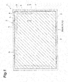
- the radiation detector 1 includes a light detection panel 7.
- the light detection panel 7 includes a substrate 2, a light-receiving unit 3, a signal line 4, a bonding pad 5, and a passivation film 6.
- the substrate 2 is, for example, a silicon substrate on which a metal oxide semiconductor field effect transistor (MOSFET) is formed.
- the light-receiving unit 3 includes a plurality of photoelectric conversion elements 3a two-dimensionally arranged in a rectangular region at the center of the substrate 2.
- the photoelectric conversion elements 3a are configured using, for example, a photodiode (PD), a thin film transistor (TFT), or the like.
- the signal line 4 is provided on the substrate 2 and electrically connects the bonding pad 5 and the light-receiving unit 3.
- the bonding pad 5 is used to extract the electric signal generated in the light-receiving unit 3 to an external circuit.
- a plurality of bonding pads 5 is disposed at predetermined intervals along two adjacent sides (an upper side and a right side in FIG. 1 ) of the outer edge of the substrate 2.
- the arrangement of the bonding pads 5 is not limited thereto.
- a plurality of bonding pads 5 may be disposed at predetermined intervals only along one side of the outer edge of the substrate 2, or may be disposed at predetermined intervals along all sides (four sides) of the outer edge of the substrate 2.
- Each bonding pad 5 is electrically connected to a corresponding plurality of photoelectric conversion elements 3a via the signal lines 4.
- the passivation film 6 is formed on the photoelectric conversion element 3a and the signal line 4.
- the passivation film 6 is formed so that the bonding pad 5 is exposed.
- a scintillator layer 8 is provided on the light detection panel 7 to cover the light-receiving unit 3.
- the scintillator layer 8 is configured by using a plurality of scintillators 8a having a columnar structure.
- the scintillators 8a receive radiation to generate light (scintillator light).
- the material of the scintillator 8a is not particularly limited, but is, for example, cesium iodide (CsI) doped with thallium (TI) or sodium (Na) having good luminous efficiency.
- the height of the scintillator layer 8 is, for example, about 600 ⁇ m. Further, the outer edge portion of the scintillator layer 8 has a tapered shape in which the height gradually decreases toward the outside of the scintillator layer 8.
- a protective layer 20 is provided on the light detection panel 7 to cover the scintillator layer 8.
- the protective layer 20 has a property of transmitting radiation and blocking moisture.
- the protective layer 20 has a light reflection film 11, a first protective film 10 that is disposed on the side of the scintillator layer 8 with respect to the light reflection film 11, and a second protective film 12 that is disposed on the side opposite to the scintillator layer 8 with respect to the light reflection film 11.
- the first protective film 10 and the second protective film 12 are, for example, organic films made of polyparaxylylene resin, poly-para-chloroxyilylene and the like.
- the light reflection film 11 is a metal film made of aluminum or silver.
- the thickness of the first protective film 10 is about 20 ⁇ m
- the thickness of the light reflection film 11 is about 200 nm (2000 ⁇ )
- the thickness of the second protective film 12 is about 10 ⁇ m.
- the thickness of the protective layer 20 is about 30.2 ⁇ m.
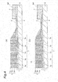
- the protective layer 20 has a main body portion 21 and an outer edge portion 22.
- the main body portion 21 is a portion that covers the scintillator layer 8.
- the first protective film 10 in the main body portion 21 is provided on the scintillator layer 8 to have the above-mentioned thickness.
- the first protective film 10 may be provided on the scintillator layer 8, while filling the space between the plurality of scintillators 8a having a columnar structure.
- the outer edge portion 22 is provided outside the main body portion 21 so as to be continuous with the main body portion 21.
- the outer edge portion 22 has an adhesive portion 23 and an extension 24.
- the adhesive portion 23 is in close contact with the light detection panel 7 in a region A between the scintillator layer 8 and the bonding pad 5.
- the adhesive portion 23 comes into close contact with the light detection panel 7.
- the adhesive portion 23 has a first portion 23a and a second portion 23b.
- the first portion 23a is a portion positioned on the side of the main body portion 21, and has a three-layer structure including the first protective film 10, the light reflection film 11 and the second protective film 12.
- the second portion 23b is a portion located opposite to the main body portion 21 across the first portion 23a, and has a two-layer structure including the first protective film 10 and the second protective film 12. Therefore, the outer edge 11a of the light reflection film 11 is located inside (on the side of the scintillator layer 8) the outer edge 20a of the protective layer 20. In the first portion 23a, the outer edge portion 10b of the first protective film 10 and the outer edge portion 12b of the second protective film 12 sandwich the light reflection film 11.
- the second portion 23b is located outside (on the side of the bonding pad 5) the outer edge portion 11b of the light reflection film 11.
- the outer edge portion 10b of the first protective film 10 and the outer edge portion 12b of the second protective film 12 are joined to each other.
- the first protective film 10 and the second protective film 12 may be integrated.
- the outer edge portion 10b of the first protective film 10 and the outer edge portion 12b of the second protective film 12 cover the outer edge portion 11b of the light reflection film 11.
- the extension 24 has a two-layer structure including the first protective film 10 and the second protective film 12, and extends from the adhesive portion 23 to the opposite side of the light detection panel 7 in a self-supporting state.
- the extension 24 is a portion located on the side of the outermost edge 20a of the protective layer 20. Therefore, the outer edge 10a of the first protective film 10 and the outer edge 12a of the second protective film 12 are located at the outer edge 20a of the protective layer 20.
- the extension 24 has a rising portion 24a and a piece portion 24b. The rising portion 24a extends toward the opposite side of the light detection panel 7 in a self-supporting state with a portion of the adhesive portion 23 on the opposite side to the main body portion 21 as a proximal end.
- the "self-supporting state” means a state in which the rising portion 24a stands up without being held or supported by any member (for example, resin or the like).
- the proximal end portion of the rising portion 24a is connected to the adhesive portion 23, but other portions of the rising portion 24a are not connected to any element of the radiation detector 1.
- the rising portion 24a extends in a direction orthogonal to the light detection panel 7 (that is, the rising portion 24a stands upright from the light detection panel 7) in a self-supporting state.
- the extending direction of the rising portion 24a is not limited thereto.
- the rising portion 24a may extend in a direction intersecting with the plane direction of the light detection panel 7 in a self-supporting state.
- the rising portion 24a may be inclined toward the bonding pad 5 side on the basis of the upright state from the light detection panel 7, or may be inclined toward the opposite side (toward the scintillator layer 8 side).
- the rising portion 24a does not need to extend along the plane, and may extend along, for example, a curved surface.
- the piece portion 24b protrudes from the upper portion of the rising portion 24a toward the bonding pad 5 side.
- the piece portion 24b protrudes in a direction parallel to the surface direction of the light detection panel 7.
- the protruding direction of the piece portion 24b is not limited thereto.
- the piece portion 24b may protrude in a direction different from the extending direction of the rising portion 24a.
- the piece portion 24b may be inclined toward the light detection panel 7 side on the basis of the state of protruding in the surface direction of the light detection panel 7, or may be inclined to the opposite side.
- the piece portion 24b does not need to protrude along the plane, and for example, may protrude along the curved surface.
- the length d1 and the length d2 represent the length of the adhesive portion 23.
- the length d1 represents the length of the first portion 23a of the adhesive portion 23
- the length d2 represents the length of the second portion 23b of the adhesive portion 23.
- the total length of the length d1 and the length d2 is, for example, about 1000 ⁇ m or less.
- the length d3 represents the height of the rising portion 24a, that is, the height of the extension 24.
- the length d3 is, for example, 80 to 250 ⁇ m.
- the length d4 represents the length of the piece portion 24b of the extension 24.
- the length d4 is, for example, about 300 ⁇ m or less.
- the length d5 represents the distance from the boundary between the adhesive portion 23 and the extension 24 to the bonding pad 5.
- the length d5 is set to be longer than the length d4 (for example, about several tens to several hundred ⁇ m) so that the extension 24 and the bonding pad 5 do not interfere with each other.
- the outer edge portion 22 of the protective layer 20 covering the scintillator layer 8 has an adhesive portion 23 coming into close contact with the light detection panel 7. This makes it possible to prevent moisture from entering the scintillator layer 8 through the gap between the protective layer 20 and the light detection panel 7. Further, the outer edge portion 22 of the protective layer 20 has an extension 24 that extends from the adhesive portion 23 to the opposite side of the light detection panel 7 in a self-supporting state. If the outer edge portion 22 of the protective layer 20 does not have the extension 24, the outer edge 20a of the protective layer 20 is included in the adhesive portion 23.
- the signal line 4 for electrically connecting the light-receiving unit 3 and the bonding pad 5 can be shortened accordingly, and the transmission speed of the electric signal can be improved. Further, it is also possible to suppress an increase in noise by the short signal line 4.
- the protective layer 20 has a light reflection film 11 that is a light reflection film, a first protective film 10 that is disposed on the side of the scintillator layer 8 with respect to the light reflection film 11, a second protective film 12 that is disposed on the side opposite to the scintillator layer 8 with respect to the light reflection film 11.
- a light reflection film 11 that is a light reflection film
- first protective film 10 that is disposed on the side of the scintillator layer 8 with respect to the light reflection film
- a second protective film 12 that is disposed on the side opposite to the scintillator layer 8 with respect to the light reflection film 11.
- the outer edge 11a of the light reflection film 11 is located inside the outer edge 20a of the protective layer 20, and the outer edge 10a of the first protective film 10 and the outer edge 12a of the second protective film 12 are located on the outer edge 20a of the protective layer 20. Further, the outer edge portion 10b of the first protective film 10 and the outer edge portion 12b of the second protective film 12 are joined to each other on the outer side of the outer edge 11a of the light reflection film 11, and cover the outer edge portion 11b of the light reflection film 11.
- the light reflection film 11 is a metal film made of aluminum or silver, it is possible to improve the light reflectivity of the light reflection film 11.
- the height of the extension 24 is 80 ⁇ m to 250 ⁇ m, the moisture resistance of the scintillator layer 8 can be more reliably secured.
- the extension 24 has a rising portion 24a, and a piece portion 24b protruding from the upper portion of the rising portion 24a toward the bonding pad 5 side. Since the extension 24 includes not only the rising portion 24a but also the piece portion 24b, the outer edge 20a of the protective layer 20 can be sufficiently away from the adhesive portion 23, and adhesion between the adhesive portion 23 and the light detection panel 7 can be more reliably secured. Even in this case, since the length of the piece portion 24b is, for example, about 300 ⁇ m or less, it is possible to narrow the region A between the scintillator layer 8 and the bonding pad 5, as compared with a case where a resin member (for example, having a width of about 900 ⁇ m as described above) is provided as in the related art.
- a resin member for example, having a width of about 900 ⁇ m as described above
- the extension 24 functions as a protective wall which protects the scintillator layer 8 from foreign matter or the like. Thus, it is possible to prevent contamination of the scintillator layer 8 at the time of bonding.
- the light detection panel 7 may be expensive. In a case where the radiation detector 1 does not satisfy the quality standard or the like in the inspection of the producing process, it is conceivable to reuse the light detection panel 7 rather than discarding the entire radiation detector 1. In that case, the scintillator layer 8 provided on the light detection panel 7 is removed, and a new scintillator layer 8 is provided on the light detection panel 7.
- the protective layer 20 needs to be removed.
- the outer edge portion 22 of the protective layer 20 has an extension 24 that extends from the adhesive portion 23 to the opposite side of the light detection panel 7 in a self-supporting state. Therefore, the protective layer 20 can be relatively easily removed, by peeling the protective layer 20 from the light detection panel 7 with the extension 24 as a starting point, for example, by grasping and pulling up the extension 24.
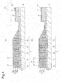
- FIGS. 3 to 7 each process of the method for producing the radiation detector 1 will be described.
- the light detection panel 7 described with reference to FIGS. 1 and 2 is prepared.
- the scintillator layer 8 is provided on the light detection panel 7 to cover the light-receiving unit 3.
- the scintillator layer 8 is formed (laminated).
- a masking member M1 is provided on the light detection panel 7 to cover the bonding pad 5.
- An example of the masking member M1 is an UV cured masking tape (hereinafter, an UV tape). Since a plurality of bonding pads 5 is disposed along the side of the outer edge of the substrate 2, the adhesive surface of the UV tape may be stuck on the light detection panel 7 to cover the bonding pad 5, while aligning the arrangement direction of the bonding pads 5 and the longitudinal direction of the UV tape.
- the thickness of the UV tape may be, for example, about 110 ⁇ m or less. In order to adjust the thickness of the masking member M1, a plurality of UV tapes may be provided to overlap each other.
- the protective layer 20 is provided on the light detection panel 7 to cover the scintillator layer 8, the region A, and the masking member M1.
- the first protective film 10 is first formed.
- the entire surface of the substrate 2 is covered with polyparaxylylene or the like by the CVD method.
- the light reflection film 11 is formed on the first protective film 10.
- an A1 film is laminated on the light reflection film 11 by a vapor deposition method.
- the bonding pad 5 may not be covered with the light reflection film 11.
- the Al film may be deposited after masking the bonding pad 5 with the masking member M2.
- a UV tape may be used as the masking member M2
- a second protective film 12 is formed.
- the entire surface of the substrate 2 is covered with polyparaxylylene or the like again by the CVD method.
- the protective layer 20 is cut on the masking member M1 by irradiating the laser beam L.
- the laser beam L is scanned along the edge portion of the scintillator layer 8 side of the masking member M1.
- the masking member M1 is removed. Specifically, the masking member M1 is removed by lowering the adhesive strength of the adhesive surface of the masking member M1 which is a UV tape.
- UV (ultraviolet) irradiation is performed toward the masking member M1. UV passes through the protective layer 20 and reaches the masking member M1.
- the adhesive surface loses the adhesive force.
- FIG. 7 the masking member M1 is removed. A portion of the cut protective layer 20 covering the masking member M1 is also removed together with the masking member M1. As a result, the bonding pad 5 is exposed.
- the bonding pad 5 is covered with the masking member M1, and the protective layer 20 is provided to cover the scintillator layer 8, the region between the scintillator layer 8 and the bonding pad 5, and the masking member M1.
- the protective layer 20 has the adhesive portion 23 that comes into close contact with the light detection panel 7 in the region A between the scintillator layer 8 and the bonding pad 5.
- a step due to the thickness of the masking member M1 is generated between the edge of the masking member M1 and the light detection panel 7, but the protective layer 20 is also formed along the step.
- the protective layer 20 has the extension 24 extending from the adhesive portion 23 to the side opposite to the light detection panel 7.
- the protective layer 20 is cut on the masking member M1, and the masking member M1 is removed.
- the bonding pad 5 is exposed, and the extension 24 is in the self-supporting state, without coming into contact with the masking member M1.
- the extension 24 includes a rising portion 24a formed along a step formed by the edge of the masking member M1, and a piece portion 24b formed between the rising portion 24a and the edge portion of the masking member M1 to which laser beam is irradiated.
- the radiation detector 1 thus produced has the adhesive portion 23 that comes into close contact with the light detection panel 7 in the region A between the scintillator layer 8 and the bonding pad 5, and the extension 24 (including the rising portion 24a and the piece portion 24b) extending from the adhesive portion 23 to the opposite side of the light detection panel 7 in the self-supporting state.
- the extension 24 including the rising portion 24a and the piece portion 24b
- the bonding pad 5 may be damaged by irradiation of the laser beam L.
- the protective layer 20 is cut on the masking member M1 in a state in which the bonding pad 5 is covered with the masking member M1.
- the masking member M1 plays a role as an absorbing layer which absorbs the laser beam L. Therefore, it is possible to prevent the bonding pad 5 from being damaged due to irradiation of the laser beam L to the bonding pad 5.
- the adhesive portion 23 and the extension 24 can be accurately shaped at the outer edge portion 22 of the protective layer 20. Even when the bonding pads 5 are disposed at predetermined intervals along not only one side of the outer edge of the substrate 2 but also a plurality of sides (for example, two to four sides), since the laser beam L may be scanned for each side, the adhesive portion 23 and the extension 24 can be easily shaped at the outer edge portion 22.
- the outer edge 11a of the light reflection film 11 may be located at the outer edge 20a of the protective layer 20, together with the outer edge 10a of the first protective film 10 and the outer edge 12a of the second protective film 12.
- the light reflection film 11 may be a resin film containing a white pigment (alumina, titanium oxide, zirconium oxide, yttrium oxide or the like).
- a resin film containing a white pigment is used as the light reflection film 11, by further laminating a metal film (for example, aluminum) and a third protective film (the same material as the first and second protective films) in this order after forming the second protective film 12, it is possible to obtain the same moisture resistance as the metal reflective film and the light output higher than that of the metal reflective film, even in the resin reflective film having poor moisture resistance. Even in this case, the light reflection film 11 having light reflectivity can be attained.
- FIG. 8 is a perspective view schematically illustrating a corner portion of the radiation detector 1
- FIG 9 is a perspective view schematically illustrating a corner portion of the radiation detector 1 as viewed from an angle different from that of FIG. 8
- a cross-section thereof is illustrated so that the scintillator layer 8 covered with the protective layer 20 can be seen, and a plurality of scintillators 8a having a columnar structure is illustrated by a dashed line.
- the outer edge portion 22 of the protective layer 20 has an adhesive portion 23 that comes into close contact with the light detection panel 7 in the region (region A in FIG.
- the scintillator layer 8 and the bonding pad 5 between the scintillator layer 8 and the bonding pad 5, and an extension 24 that extends from the adhesive portion 23 to the opposite side of the light detection panel 7 in the self-supporting state.
- the rising portion 24a is inclined toward the bonding pad 5, and the piece portion 24b may also be inclined toward the bonding pad 5.
- the connecting portion between the rising portion 24a and the piece portion 24b may not be bent at right angles but may be smoothly bent.
Claims (7)
- Détecteur de rayonnement comprenant :un panneau de détection de lumière (7) qui comporte une unité de réception de lumière (3), et une plaquette de liaison (5) qui est connectée électriquement à l'unité de réception de lumière (3) ;une couche de scintillateur (8) qui est prévue sur le panneau de détection de lumière (7) pour couvrir l'unité de réception de lumière (3) ; etune couche de protection (20) qui est prévue sur le panneau de détection de lumière (7) pour recouvrir la couche de scintillateur (8),dans laquelle une partie de bord extérieur de la couche de protection (20) comporte une partie adhésive (23) qui est en contact étroit avec le panneau de détection de lumière (7) dans une région située entre la couche de scintillateur (8) et la plaquette de liaison (5), etcaractérisé en ce que la partie de bord extérieur de la couche de protection (20) comporte en outre une extension (24), comprenant une partie ascendante (24a), qui s'étend de la partie adhésive (23) à un côté opposé du panneau de détection de lumière (7) dans un état autoportant dans lequel la partie ascendante (24a) se dresse au-dessus du panneau de détection de lumière (7).
- Détecteur de rayonnement selon la revendication 1,
dans lequel la couche de protection (20) comporte
un film de réflexion de la lumière (11),
un premier film de protection (10) qui est disposé côté couche de scintillateur par rapport au film de réflexion de la lumière (11), et
un deuxième film de protection (12) qui est disposé sur le côté opposé de la couche de scintillateur (8) par rapport au film de réflexion de la lumière (11). - Détecteur de rayonnement selon la revendication 2,
dans lequel un bord extérieur du film de réflexion de la lumière (11) est situé à l'intérieur d'un bord extérieur de la couche de protection (20),
la partie de bord extérieur du premier film de protection (10) et la partie de bord extérieur du second film de protection (12) sont situées au bord extérieur de la couche de protection (20), et
la partie de bord extérieur du premier film de protection (10) et la partie de bord extérieur du second film de protection (12) sont liées entre elles à l'extérieur du bord extérieur du film de réflexion de la lumière (11) et recouvrent la partie de bord extérieur du film de réflexion de la lumière (11). - Détecteur de rayonnement selon la revendication 2 ou 3, dans lequel le film de réflexion de la lumière (11) est un film métallique en aluminium ou en argent.
- Détecteur de rayonnement selon la revendication 2 ou 3, dans lequel le film de réflexion de la lumière (11) est un film de résine contenant un pigment blanc.
- Détecteur de rayonnement selon l'une quelconque des revendications 1 à 5, dans lequel une hauteur de l'extension (24) est de 80 µm à 250 µm.
- Procédé de production d'un détecteur de rayonnement selon la revendication 1, le procédé comportant les étapes consistant à :préparer panneau de détection de lumière (7) ayant une unité de réception de lumière (3) et une plaquette de liaison (5) connectée électriquement à l'unité de réception de lumière (3), et prévoir une couche de scintillateur (8) sur le panneau de détection de lumière (7) pour couvrir l'unité de réception de lumière (3) ;prévoir un élément de masquage (M1) sur le panneau de détection de lumière (7) pour recouvrir la plaquette de liaison (5) ;prévoir une couche de protection (20) sur le panneau de détection de lumière (7) pour recouvrir la couche de scintillateur (8), une région entre la couche de scintillateur (8) et la plaquette de liaison (5), et l'élément de masquage (M1) ;couper la couche de protection (20) sur l'élément de masquage (M1) en appliquant un faisceau laser le long d'une partie de bord du côté scintillateur de l'élément de masquage (M1) ; et retirer l'élément de masquage (M1).
Applications Claiming Priority (2)
| Application Number | Priority Date | Filing Date | Title |
|---|---|---|---|
| JP2015085687A JP6487263B2 (ja) | 2015-04-20 | 2015-04-20 | 放射線検出器及びその製造方法 |
| PCT/JP2016/052919 WO2016170812A1 (fr) | 2015-04-20 | 2016-02-01 | Détecteur de rayonnement et son procédé de fabrication |
Publications (3)
| Publication Number | Publication Date |
|---|---|
| EP3287812A1 EP3287812A1 (fr) | 2018-02-28 |
| EP3287812A4 EP3287812A4 (fr) | 2018-09-26 |
| EP3287812B1 true EP3287812B1 (fr) | 2020-01-15 |
Family
ID=57143836
Family Applications (1)
| Application Number | Title | Priority Date | Filing Date |
|---|---|---|---|
| EP16782834.2A Active EP3287812B1 (fr) | 2015-04-20 | 2016-02-01 | Détecteur de rayonnement et son procédé de fabrication |
Country Status (7)
| Country | Link |
|---|---|
| US (1) | US10379229B2 (fr) |
| EP (1) | EP3287812B1 (fr) |
| JP (1) | JP6487263B2 (fr) |
| KR (1) | KR102434183B1 (fr) |
| CN (1) | CN107533142B (fr) |
| TW (1) | TWI674428B (fr) |
| WO (1) | WO2016170812A1 (fr) |
Families Citing this family (7)
| Publication number | Priority date | Publication date | Assignee | Title |
|---|---|---|---|---|
| JP6487263B2 (ja) * | 2015-04-20 | 2019-03-20 | 浜松ホトニクス株式会社 | 放射線検出器及びその製造方法 |
| KR102119733B1 (ko) * | 2017-05-12 | 2020-06-17 | 주식회사 에이치앤아비즈 | 신틸레이터 패널 |
| CN109659385A (zh) * | 2017-10-10 | 2019-04-19 | 群创光电股份有限公司 | 感测装置 |
| CN110323235A (zh) * | 2018-03-29 | 2019-10-11 | 夏普株式会社 | 摄像面板 |
| JP2019174365A (ja) * | 2018-03-29 | 2019-10-10 | シャープ株式会社 | 撮像パネル |
| JP7345385B2 (ja) | 2019-12-25 | 2023-09-15 | 浜松ホトニクス株式会社 | 放射線検出器及び放射線検出器の製造方法 |
| JP2021103122A (ja) | 2019-12-25 | 2021-07-15 | 浜松ホトニクス株式会社 | 放射線検出器及び放射線検出器の製造方法 |
Family Cites Families (71)
| Publication number | Priority date | Publication date | Assignee | Title |
|---|---|---|---|---|
| US3855035A (en) * | 1972-06-22 | 1974-12-17 | Varian Associates | Image intensifier plate and method and compositions for manufacturing same |
| US3917950A (en) * | 1974-04-08 | 1975-11-04 | United States Steel Corp | Fluoroscopic screen which is optically homogeneous |
| JPS6034709B2 (ja) * | 1975-11-28 | 1985-08-10 | 株式会社日立メデイコ | アンガ−形γカメラ |
| US5148029A (en) * | 1991-09-23 | 1992-09-15 | Siemens Gammasonics, Inc. | Improved seal scintillation camera module and method of making it |
| US7019301B2 (en) * | 1997-02-14 | 2006-03-28 | Hamamatsu Photonics K.K. | Radiation detection device and method of making the same |
| CN1844953B (zh) * | 1997-02-14 | 2012-06-27 | 浜松光子学株式会社 | 放射线检测元件及其制造方法 |
| US6172371B1 (en) * | 1998-06-15 | 2001-01-09 | General Electric Company | Robust cover plate for radiation imager |
| EP1118878B1 (fr) * | 1998-06-18 | 2005-08-17 | Hamamatsu Photonics K.K. | Panneau de scintillateur, capteur d'image radiologique et procede de leur production |
| EP1156346B1 (fr) * | 1998-06-18 | 2006-10-04 | Hamamatsu Photonics K.K. | Panneau de scintillateur et capteur d'image de rayonnement |
| US7034306B2 (en) * | 1998-06-18 | 2006-04-25 | Hamamatsu Photonics K.K. | Scintillator panel and radiation image sensor |
| JP4317154B2 (ja) * | 1998-06-18 | 2009-08-19 | 浜松ホトニクス株式会社 | シンチレータパネルおよび放射線イメージセンサ |
| CN1163762C (zh) * | 1998-06-18 | 2004-08-25 | 浜松光子学株式会社 | 闪烁体面板和放射线图象传感器 |
| CN100587519C (zh) * | 1999-04-16 | 2010-02-03 | 浜松光子学株式会社 | 闪烁器面板和放射线图象传感器 |
| CN1869732B (zh) * | 2000-01-13 | 2010-11-17 | 浜松光子学株式会社 | 放射线图像传感器及闪烁器板 |
| US7151263B2 (en) * | 2000-05-19 | 2006-12-19 | Hamamatsu Photonics K.K. | Radiation detector and method of manufacture thereof |
| JP4283427B2 (ja) * | 2000-08-03 | 2009-06-24 | 浜松ホトニクス株式会社 | 放射線検出器およびシンチレータパネル |
| JP4447752B2 (ja) * | 2000-08-03 | 2010-04-07 | 浜松ホトニクス株式会社 | 放射線検出器 |
| USRE42281E1 (en) * | 2000-09-11 | 2011-04-12 | Hamamatsu Photonics K.K. | Scintillator panel, radiation image sensor and methods of producing them |
| WO2002023219A1 (fr) * | 2000-09-11 | 2002-03-21 | Hamamatsu Photonics K.K. | Panneau de scintillateur, capteur d'images radiographiques et procedes de production |
| DE20021660U1 (de) * | 2000-12-20 | 2002-05-02 | Alanod Al Veredlung Gmbh | Verbundmaterial |
| US6835936B2 (en) * | 2001-02-07 | 2004-12-28 | Canon Kabushiki Kaisha | Scintillator panel, method of manufacturing scintillator panel, radiation detection device, and radiation detection system |
| US6847041B2 (en) * | 2001-02-09 | 2005-01-25 | Canon Kabushiki Kaisha | Scintillator panel, radiation detector and manufacture methods thereof |
| US6803583B2 (en) * | 2001-03-21 | 2004-10-12 | M.E. Taylor Engineering Inc. | Scintillator for electron microscope and method of making |
| US6720561B2 (en) * | 2001-12-06 | 2004-04-13 | General Electric Company | Direct CsI scintillator coating for improved digital X-ray detector assembly longevity |
| US7126130B2 (en) * | 2001-12-06 | 2006-10-24 | General Electric Company | Direct scintillator coating for radiation detector assembly longevity |
| JP4280507B2 (ja) * | 2003-01-24 | 2009-06-17 | キヤノン株式会社 | 放射線検出装置の製造方法 |
| US7473903B2 (en) * | 2003-02-12 | 2009-01-06 | General Electric Company | Method and apparatus for deposited hermetic cover for digital X-ray panel |
| JP4289913B2 (ja) * | 2003-03-12 | 2009-07-01 | キヤノン株式会社 | 放射線検出装置及びその製造方法 |
| US7355184B2 (en) * | 2003-04-07 | 2008-04-08 | Canon Kabushiki Kaisha | Radiation detecting apparatus and method for manufacturing the same |
| US7112802B2 (en) * | 2003-04-11 | 2006-09-26 | Canon Kabushiki Kaisha | Scintillator panel, radiation detecting apparatus, and radiation detection system |
| US7315027B2 (en) * | 2003-10-22 | 2008-01-01 | Canon Kabushiki Kaisha | Radiation detection device, scintillator panel, method of making the same, making apparatus, and radiation image pick-up system |
| US7193218B2 (en) * | 2003-10-29 | 2007-03-20 | Canon Kabushiki Kaisha | Radiation detection device, method of producing the same, and radiation image pick-up system |
| US7067817B2 (en) * | 2004-01-29 | 2006-06-27 | Hamamatsu Photonics K.K. | Radiation image sensor and making method of same |
| JP4266898B2 (ja) * | 2004-08-10 | 2009-05-20 | キヤノン株式会社 | 放射線検出装置とその製造方法および放射線撮像システム |
| JP4208790B2 (ja) * | 2004-08-10 | 2009-01-14 | キヤノン株式会社 | 放射線検出装置の製造方法 |
| CN101002110B (zh) * | 2004-08-10 | 2010-12-08 | 佳能株式会社 | 放射线探测装置、闪烁体板及其制造方法和放射线探测系统 |
| JP4886245B2 (ja) * | 2005-08-26 | 2012-02-29 | 株式会社東芝 | 放射線検出器 |
| US7910892B2 (en) * | 2005-12-22 | 2011-03-22 | Kabushiki Kaisha Toshiba | Method for manufacturing X-ray detector and X-ray detector |
| JP4921180B2 (ja) * | 2006-01-25 | 2012-04-25 | キヤノン株式会社 | 放射線検出装置及び放射線撮像システム |
| JP4920994B2 (ja) * | 2006-03-02 | 2012-04-18 | キヤノン株式会社 | シンチレータパネル、放射線検出装置及び放射線検出システム |
| JP5089195B2 (ja) * | 2006-03-02 | 2012-12-05 | キヤノン株式会社 | 放射線検出装置、シンチレータパネル、放射線検出システム及び放射線検出装置の製造方法 |
| US7405406B1 (en) * | 2006-04-21 | 2008-07-29 | Radiation Monitoring Devices, Inc. | Two-sided scintillation detectors and related methods |
| EP1860463A1 (fr) * | 2006-05-23 | 2007-11-28 | Agfa HealthCare NV | Phosphore de rayonnement d'image ou panneau scintillant |
| DE102006038969B4 (de) * | 2006-08-21 | 2013-02-28 | Siemens Aktiengesellschaft | Röntgenkonverterelement und Verfahren zu dessen Herstellung |
| JP4764407B2 (ja) * | 2007-11-20 | 2011-09-07 | 東芝電子管デバイス株式会社 | 放射線検出器及びその製造方法 |
| FR2948379B1 (fr) * | 2009-07-21 | 2011-08-19 | Saint Gobain Cristaux Et Detecteurs | Scintillateur en halogenure de terre rare revetu d'un absorbeur ou reflecteur de lumiere |
| JP5562134B2 (ja) * | 2010-06-17 | 2014-07-30 | キヤノン株式会社 | 放射線検出装置、その製造方法及び放射線撮像システム |
| JP5649872B2 (ja) * | 2010-08-24 | 2015-01-07 | 浜松ホトニクス株式会社 | 放射線検出器の製造方法 |
| JP5456013B2 (ja) * | 2010-12-17 | 2014-03-26 | 富士フイルム株式会社 | 放射線撮像装置 |
| JP5629593B2 (ja) * | 2011-02-01 | 2014-11-19 | 株式会社東芝 | 放射線検出器 |
| JP5728250B2 (ja) * | 2011-03-01 | 2015-06-03 | キヤノン株式会社 | 放射線検出装置、シンチレータパネル、それらの製造方法、および放射線検出システム |
| KR101266554B1 (ko) * | 2011-05-09 | 2013-05-27 | 주식회사 아비즈알 | 신틸레이터 패널 및 신틸레이터 패널을 제조하는 방법 |
| JP5911274B2 (ja) * | 2011-11-28 | 2016-04-27 | キヤノン株式会社 | 放射線検出装置及び放射線撮像システム |
| KR101925895B1 (ko) * | 2011-12-29 | 2018-12-07 | 삼성디스플레이 주식회사 | 엑스선 검출용 패널 및 이의 제조방법 |
| US8829454B2 (en) * | 2012-02-27 | 2014-09-09 | Analog Devices, Inc. | Compact sensor module |
| JP6200171B2 (ja) * | 2012-06-04 | 2017-09-20 | キヤノン株式会社 | 放射線検出装置及び撮像システム |
| JP6071283B2 (ja) * | 2012-07-04 | 2017-02-01 | キヤノン株式会社 | 放射線検出装置及びその製造方法 |
| JP5922518B2 (ja) * | 2012-07-20 | 2016-05-24 | 浜松ホトニクス株式会社 | シンチレータパネル及び放射線検出器 |
| JP2014081364A (ja) * | 2012-09-27 | 2014-05-08 | Fujifilm Corp | 放射線画像検出装置 |
| JP6092568B2 (ja) * | 2012-10-11 | 2017-03-08 | キヤノン株式会社 | 放射線検出装置及び放射線検出システム |
| JP6298264B2 (ja) * | 2012-10-31 | 2018-03-20 | キヤノン株式会社 | シンチレータ、放射線検出装置、および、それらの製造方法 |
| US9116022B2 (en) * | 2012-12-07 | 2015-08-25 | Analog Devices, Inc. | Compact sensor module |
| JP6100045B2 (ja) * | 2013-03-19 | 2017-03-22 | キヤノン株式会社 | 放射線検出装置、放射線検出システム及び放射線検出装置の製造方法 |
| JP6200173B2 (ja) * | 2013-03-21 | 2017-09-20 | キヤノン株式会社 | 放射線検出装置及び放射線検出システム |
| WO2014187502A1 (fr) * | 2013-05-24 | 2014-11-27 | Teledyne Dalsa B.V. | Structure de protection contre l'humidité pour dispositif et son procédé de fabrication |
| US20140374608A1 (en) * | 2013-06-19 | 2014-12-25 | Canon Kabushiki Kaisha | Radiation detection apparatus and method of manufacturing the same |
| JP2015096823A (ja) * | 2013-11-15 | 2015-05-21 | 浜松ホトニクス株式会社 | 放射線検出器、及び放射線検出器の製造方法 |
| JP2016038279A (ja) * | 2014-08-07 | 2016-03-22 | コニカミノルタ株式会社 | シンチレータパネルおよびこれを備えた放射線検出器 |
| JP6488635B2 (ja) * | 2014-10-23 | 2019-03-27 | コニカミノルタ株式会社 | シンチレータパネル及び放射線検出器 |
| JP6512830B2 (ja) * | 2015-01-09 | 2019-05-15 | キヤノン株式会社 | 放射線撮像装置、その製造方法及び放射線検査装置 |
| JP6487263B2 (ja) * | 2015-04-20 | 2019-03-20 | 浜松ホトニクス株式会社 | 放射線検出器及びその製造方法 |
-
2015
- 2015-04-20 JP JP2015085687A patent/JP6487263B2/ja active Active
-
2016
- 2016-02-01 CN CN201680022754.4A patent/CN107533142B/zh active Active
- 2016-02-01 EP EP16782834.2A patent/EP3287812B1/fr active Active
- 2016-02-01 KR KR1020177026043A patent/KR102434183B1/ko active IP Right Grant
- 2016-02-01 US US15/563,641 patent/US10379229B2/en active Active
- 2016-02-01 WO PCT/JP2016/052919 patent/WO2016170812A1/fr active Application Filing
- 2016-02-18 TW TW105104763A patent/TWI674428B/zh active
Non-Patent Citations (1)
| Title |
|---|
| None * |
Also Published As
| Publication number | Publication date |
|---|---|
| US10379229B2 (en) | 2019-08-13 |
| JP6487263B2 (ja) | 2019-03-20 |
| JP2016205916A (ja) | 2016-12-08 |
| WO2016170812A1 (fr) | 2016-10-27 |
| EP3287812A1 (fr) | 2018-02-28 |
| TWI674428B (zh) | 2019-10-11 |
| KR102434183B1 (ko) | 2022-08-19 |
| KR20170138403A (ko) | 2017-12-15 |
| CN107533142A (zh) | 2018-01-02 |
| CN107533142B (zh) | 2019-09-20 |
| EP3287812A4 (fr) | 2018-09-26 |
| US20180074216A1 (en) | 2018-03-15 |
| TW201638611A (zh) | 2016-11-01 |
Similar Documents
| Publication | Publication Date | Title |
|---|---|---|
| EP3287812B1 (fr) | Détecteur de rayonnement et son procédé de fabrication | |
| US10514470B2 (en) | Radiation detector, and method for producing radiation detector | |
| KR100514547B1 (ko) | 방사선검출소자및그제조방법 | |
| JP2019164163A (ja) | 放射線検出器 | |
| JP2018084589A (ja) | 放射線検出器の製造方法 | |
| US11644581B2 (en) | Radiation detector and method for manufacturing radiation detector | |
| JP5911330B2 (ja) | 放射線検出器およびその製造方法。 | |
| US11762110B2 (en) | Radiation detector and method for manufacturing radiation detector | |
| JP2020177033A (ja) | 放射線検出器 | |
| CN111149176B (zh) | 闪烁器面板及放射线检测器 |
Legal Events
| Date | Code | Title | Description |
|---|---|---|---|
| STAA | Information on the status of an ep patent application or granted ep patent |
Free format text: STATUS: THE INTERNATIONAL PUBLICATION HAS BEEN MADE |
|
| PUAI | Public reference made under article 153(3) epc to a published international application that has entered the european phase |
Free format text: ORIGINAL CODE: 0009012 |
|
| STAA | Information on the status of an ep patent application or granted ep patent |
Free format text: STATUS: REQUEST FOR EXAMINATION WAS MADE |
|
| 17P | Request for examination filed |
Effective date: 20171117 |
|
| AK | Designated contracting states |
Kind code of ref document: A1 Designated state(s): AL AT BE BG CH CY CZ DE DK EE ES FI FR GB GR HR HU IE IS IT LI LT LU LV MC MK MT NL NO PL PT RO RS SE SI SK SM TR |
|
| AX | Request for extension of the european patent |
Extension state: BA ME |
|
| DAV | Request for validation of the european patent (deleted) | ||
| DAX | Request for extension of the european patent (deleted) | ||
| A4 | Supplementary search report drawn up and despatched |
Effective date: 20180828 |
|
| RIC1 | Information provided on ipc code assigned before grant |
Ipc: H01L 27/146 20060101ALI20180822BHEP Ipc: G01T 1/20 20060101AFI20180822BHEP |
|
| GRAP | Despatch of communication of intention to grant a patent |
Free format text: ORIGINAL CODE: EPIDOSNIGR1 |
|
| STAA | Information on the status of an ep patent application or granted ep patent |
Free format text: STATUS: GRANT OF PATENT IS INTENDED |
|
| INTG | Intention to grant announced |
Effective date: 20190418 |
|
| GRAJ | Information related to disapproval of communication of intention to grant by the applicant or resumption of examination proceedings by the epo deleted |
Free format text: ORIGINAL CODE: EPIDOSDIGR1 |
|
| STAA | Information on the status of an ep patent application or granted ep patent |
Free format text: STATUS: REQUEST FOR EXAMINATION WAS MADE |
|
| GRAP | Despatch of communication of intention to grant a patent |
Free format text: ORIGINAL CODE: EPIDOSNIGR1 |
|
| STAA | Information on the status of an ep patent application or granted ep patent |
Free format text: STATUS: GRANT OF PATENT IS INTENDED |
|
| INTC | Intention to grant announced (deleted) | ||
| INTG | Intention to grant announced |
Effective date: 20190910 |
|
| GRAS | Grant fee paid |
Free format text: ORIGINAL CODE: EPIDOSNIGR3 |
|
| GRAA | (expected) grant |
Free format text: ORIGINAL CODE: 0009210 |
|
| STAA | Information on the status of an ep patent application or granted ep patent |
Free format text: STATUS: THE PATENT HAS BEEN GRANTED |
|
| AK | Designated contracting states |
Kind code of ref document: B1 Designated state(s): AL AT BE BG CH CY CZ DE DK EE ES FI FR GB GR HR HU IE IS IT LI LT LU LV MC MK MT NL NO PL PT RO RS SE SI SK SM TR |
|
| REG | Reference to a national code |
Ref country code: CH Ref legal event code: EP Ref country code: GB Ref legal event code: FG4D |
|
| REG | Reference to a national code |
Ref country code: IE Ref legal event code: FG4D |
|
| REG | Reference to a national code |
Ref country code: DE Ref legal event code: R096 Ref document number: 602016028387 Country of ref document: DE |
|
| REG | Reference to a national code |
Ref country code: AT Ref legal event code: REF Ref document number: 1225630 Country of ref document: AT Kind code of ref document: T Effective date: 20200215 |
|
| REG | Reference to a national code |
Ref country code: NL Ref legal event code: FP |
|
| REG | Reference to a national code |
Ref country code: LT Ref legal event code: MG4D |
|
| PG25 | Lapsed in a contracting state [announced via postgrant information from national office to epo] |
Ref country code: FI Free format text: LAPSE BECAUSE OF FAILURE TO SUBMIT A TRANSLATION OF THE DESCRIPTION OR TO PAY THE FEE WITHIN THE PRESCRIBED TIME-LIMIT Effective date: 20200115 Ref country code: NO Free format text: LAPSE BECAUSE OF FAILURE TO SUBMIT A TRANSLATION OF THE DESCRIPTION OR TO PAY THE FEE WITHIN THE PRESCRIBED TIME-LIMIT Effective date: 20200415 Ref country code: RS Free format text: LAPSE BECAUSE OF FAILURE TO SUBMIT A TRANSLATION OF THE DESCRIPTION OR TO PAY THE FEE WITHIN THE PRESCRIBED TIME-LIMIT Effective date: 20200115 Ref country code: PT Free format text: LAPSE BECAUSE OF FAILURE TO SUBMIT A TRANSLATION OF THE DESCRIPTION OR TO PAY THE FEE WITHIN THE PRESCRIBED TIME-LIMIT Effective date: 20200607 |
|
| PG25 | Lapsed in a contracting state [announced via postgrant information from national office to epo] |
Ref country code: IS Free format text: LAPSE BECAUSE OF FAILURE TO SUBMIT A TRANSLATION OF THE DESCRIPTION OR TO PAY THE FEE WITHIN THE PRESCRIBED TIME-LIMIT Effective date: 20200515 Ref country code: BG Free format text: LAPSE BECAUSE OF FAILURE TO SUBMIT A TRANSLATION OF THE DESCRIPTION OR TO PAY THE FEE WITHIN THE PRESCRIBED TIME-LIMIT Effective date: 20200415 Ref country code: GR Free format text: LAPSE BECAUSE OF FAILURE TO SUBMIT A TRANSLATION OF THE DESCRIPTION OR TO PAY THE FEE WITHIN THE PRESCRIBED TIME-LIMIT Effective date: 20200416 Ref country code: SE Free format text: LAPSE BECAUSE OF FAILURE TO SUBMIT A TRANSLATION OF THE DESCRIPTION OR TO PAY THE FEE WITHIN THE PRESCRIBED TIME-LIMIT Effective date: 20200115 Ref country code: LV Free format text: LAPSE BECAUSE OF FAILURE TO SUBMIT A TRANSLATION OF THE DESCRIPTION OR TO PAY THE FEE WITHIN THE PRESCRIBED TIME-LIMIT Effective date: 20200115 Ref country code: HR Free format text: LAPSE BECAUSE OF FAILURE TO SUBMIT A TRANSLATION OF THE DESCRIPTION OR TO PAY THE FEE WITHIN THE PRESCRIBED TIME-LIMIT Effective date: 20200115 |
|
| REG | Reference to a national code |
Ref country code: CH Ref legal event code: PL |
|
| REG | Reference to a national code |
Ref country code: DE Ref legal event code: R097 Ref document number: 602016028387 Country of ref document: DE |
|
| REG | Reference to a national code |
Ref country code: BE Ref legal event code: MM Effective date: 20200229 |
|
| PG25 | Lapsed in a contracting state [announced via postgrant information from national office to epo] |
Ref country code: DK Free format text: LAPSE BECAUSE OF FAILURE TO SUBMIT A TRANSLATION OF THE DESCRIPTION OR TO PAY THE FEE WITHIN THE PRESCRIBED TIME-LIMIT Effective date: 20200115 Ref country code: ES Free format text: LAPSE BECAUSE OF FAILURE TO SUBMIT A TRANSLATION OF THE DESCRIPTION OR TO PAY THE FEE WITHIN THE PRESCRIBED TIME-LIMIT Effective date: 20200115 Ref country code: LT Free format text: LAPSE BECAUSE OF FAILURE TO SUBMIT A TRANSLATION OF THE DESCRIPTION OR TO PAY THE FEE WITHIN THE PRESCRIBED TIME-LIMIT Effective date: 20200115 Ref country code: MC Free format text: LAPSE BECAUSE OF FAILURE TO SUBMIT A TRANSLATION OF THE DESCRIPTION OR TO PAY THE FEE WITHIN THE PRESCRIBED TIME-LIMIT Effective date: 20200115 Ref country code: RO Free format text: LAPSE BECAUSE OF FAILURE TO SUBMIT A TRANSLATION OF THE DESCRIPTION OR TO PAY THE FEE WITHIN THE PRESCRIBED TIME-LIMIT Effective date: 20200115 Ref country code: SK Free format text: LAPSE BECAUSE OF FAILURE TO SUBMIT A TRANSLATION OF THE DESCRIPTION OR TO PAY THE FEE WITHIN THE PRESCRIBED TIME-LIMIT Effective date: 20200115 Ref country code: CZ Free format text: LAPSE BECAUSE OF FAILURE TO SUBMIT A TRANSLATION OF THE DESCRIPTION OR TO PAY THE FEE WITHIN THE PRESCRIBED TIME-LIMIT Effective date: 20200115 Ref country code: LU Free format text: LAPSE BECAUSE OF NON-PAYMENT OF DUE FEES Effective date: 20200201 Ref country code: EE Free format text: LAPSE BECAUSE OF FAILURE TO SUBMIT A TRANSLATION OF THE DESCRIPTION OR TO PAY THE FEE WITHIN THE PRESCRIBED TIME-LIMIT Effective date: 20200115 Ref country code: SM Free format text: LAPSE BECAUSE OF FAILURE TO SUBMIT A TRANSLATION OF THE DESCRIPTION OR TO PAY THE FEE WITHIN THE PRESCRIBED TIME-LIMIT Effective date: 20200115 |
|
| REG | Reference to a national code |
Ref country code: AT Ref legal event code: MK05 Ref document number: 1225630 Country of ref document: AT Kind code of ref document: T Effective date: 20200115 |
|
| PLBE | No opposition filed within time limit |
Free format text: ORIGINAL CODE: 0009261 |
|
| STAA | Information on the status of an ep patent application or granted ep patent |
Free format text: STATUS: NO OPPOSITION FILED WITHIN TIME LIMIT |
|
| PG25 | Lapsed in a contracting state [announced via postgrant information from national office to epo] |
Ref country code: LI Free format text: LAPSE BECAUSE OF NON-PAYMENT OF DUE FEES Effective date: 20200229 Ref country code: CH Free format text: LAPSE BECAUSE OF NON-PAYMENT OF DUE FEES Effective date: 20200229 |
|
| 26N | No opposition filed |
Effective date: 20201016 |
|
| PG25 | Lapsed in a contracting state [announced via postgrant information from national office to epo] |
Ref country code: IT Free format text: LAPSE BECAUSE OF FAILURE TO SUBMIT A TRANSLATION OF THE DESCRIPTION OR TO PAY THE FEE WITHIN THE PRESCRIBED TIME-LIMIT Effective date: 20200115 Ref country code: IE Free format text: LAPSE BECAUSE OF NON-PAYMENT OF DUE FEES Effective date: 20200201 Ref country code: AT Free format text: LAPSE BECAUSE OF FAILURE TO SUBMIT A TRANSLATION OF THE DESCRIPTION OR TO PAY THE FEE WITHIN THE PRESCRIBED TIME-LIMIT Effective date: 20200115 |
|
| PG25 | Lapsed in a contracting state [announced via postgrant information from national office to epo] |
Ref country code: PL Free format text: LAPSE BECAUSE OF FAILURE TO SUBMIT A TRANSLATION OF THE DESCRIPTION OR TO PAY THE FEE WITHIN THE PRESCRIBED TIME-LIMIT Effective date: 20200115 Ref country code: SI Free format text: LAPSE BECAUSE OF FAILURE TO SUBMIT A TRANSLATION OF THE DESCRIPTION OR TO PAY THE FEE WITHIN THE PRESCRIBED TIME-LIMIT Effective date: 20200115 Ref country code: BE Free format text: LAPSE BECAUSE OF NON-PAYMENT OF DUE FEES Effective date: 20200229 |
|
| PG25 | Lapsed in a contracting state [announced via postgrant information from national office to epo] |
Ref country code: TR Free format text: LAPSE BECAUSE OF FAILURE TO SUBMIT A TRANSLATION OF THE DESCRIPTION OR TO PAY THE FEE WITHIN THE PRESCRIBED TIME-LIMIT Effective date: 20200115 Ref country code: MT Free format text: LAPSE BECAUSE OF FAILURE TO SUBMIT A TRANSLATION OF THE DESCRIPTION OR TO PAY THE FEE WITHIN THE PRESCRIBED TIME-LIMIT Effective date: 20200115 Ref country code: CY Free format text: LAPSE BECAUSE OF FAILURE TO SUBMIT A TRANSLATION OF THE DESCRIPTION OR TO PAY THE FEE WITHIN THE PRESCRIBED TIME-LIMIT Effective date: 20200115 |
|
| PGFP | Annual fee paid to national office [announced via postgrant information from national office to epo] |
Ref country code: FR Payment date: 20220118 Year of fee payment: 7 |
|
| PG25 | Lapsed in a contracting state [announced via postgrant information from national office to epo] |
Ref country code: MK Free format text: LAPSE BECAUSE OF FAILURE TO SUBMIT A TRANSLATION OF THE DESCRIPTION OR TO PAY THE FEE WITHIN THE PRESCRIBED TIME-LIMIT Effective date: 20200115 Ref country code: AL Free format text: LAPSE BECAUSE OF FAILURE TO SUBMIT A TRANSLATION OF THE DESCRIPTION OR TO PAY THE FEE WITHIN THE PRESCRIBED TIME-LIMIT Effective date: 20200115 |
|
| P01 | Opt-out of the competence of the unified patent court (upc) registered |
Effective date: 20230517 |
|
| PGFP | Annual fee paid to national office [announced via postgrant information from national office to epo] |
Ref country code: NL Payment date: 20240108 Year of fee payment: 9 |
|
| PGFP | Annual fee paid to national office [announced via postgrant information from national office to epo] |
Ref country code: DE Payment date: 20231228 Year of fee payment: 9 Ref country code: GB Payment date: 20240108 Year of fee payment: 9 |