EP3278917A1 - Verfahren zum punktschweissen eines plattierten stahlblechs - Google Patents
Verfahren zum punktschweissen eines plattierten stahlblechs Download PDFInfo
- Publication number
- EP3278917A1 EP3278917A1 EP16773050.6A EP16773050A EP3278917A1 EP 3278917 A1 EP3278917 A1 EP 3278917A1 EP 16773050 A EP16773050 A EP 16773050A EP 3278917 A1 EP3278917 A1 EP 3278917A1
- Authority
- EP
- European Patent Office
- Prior art keywords
- welding
- steel sheets
- plating
- cracking
- spot welding
- Prior art date
- Legal status (The legal status is an assumption and is not a legal conclusion. Google has not performed a legal analysis and makes no representation as to the accuracy of the status listed.)
- Granted
Links
Images


Classifications
-
- B—PERFORMING OPERATIONS; TRANSPORTING
- B23—MACHINE TOOLS; METAL-WORKING NOT OTHERWISE PROVIDED FOR
- B23K—SOLDERING OR UNSOLDERING; WELDING; CLADDING OR PLATING BY SOLDERING OR WELDING; CUTTING BY APPLYING HEAT LOCALLY, e.g. FLAME CUTTING; WORKING BY LASER BEAM
- B23K11/00—Resistance welding; Severing by resistance heating
- B23K11/10—Spot welding; Stitch welding
- B23K11/11—Spot welding
- B23K11/115—Spot welding by means of two electrodes placed opposite one another on both sides of the welded parts
-
- B—PERFORMING OPERATIONS; TRANSPORTING
- B23—MACHINE TOOLS; METAL-WORKING NOT OTHERWISE PROVIDED FOR
- B23K—SOLDERING OR UNSOLDERING; WELDING; CLADDING OR PLATING BY SOLDERING OR WELDING; CUTTING BY APPLYING HEAT LOCALLY, e.g. FLAME CUTTING; WORKING BY LASER BEAM
- B23K11/00—Resistance welding; Severing by resistance heating
- B23K11/16—Resistance welding; Severing by resistance heating taking account of the properties of the material to be welded
- B23K11/163—Welding of coated materials
- B23K11/166—Welding of coated materials of galvanized or tinned materials
-
- B—PERFORMING OPERATIONS; TRANSPORTING
- B23—MACHINE TOOLS; METAL-WORKING NOT OTHERWISE PROVIDED FOR
- B23K—SOLDERING OR UNSOLDERING; WELDING; CLADDING OR PLATING BY SOLDERING OR WELDING; CUTTING BY APPLYING HEAT LOCALLY, e.g. FLAME CUTTING; WORKING BY LASER BEAM
- B23K11/00—Resistance welding; Severing by resistance heating
- B23K11/34—Preliminary treatment
-
- B—PERFORMING OPERATIONS; TRANSPORTING
- B23—MACHINE TOOLS; METAL-WORKING NOT OTHERWISE PROVIDED FOR
- B23K—SOLDERING OR UNSOLDERING; WELDING; CLADDING OR PLATING BY SOLDERING OR WELDING; CUTTING BY APPLYING HEAT LOCALLY, e.g. FLAME CUTTING; WORKING BY LASER BEAM
- B23K26/00—Working by laser beam, e.g. welding, cutting or boring
- B23K26/36—Removing material
-
- B—PERFORMING OPERATIONS; TRANSPORTING
- B23—MACHINE TOOLS; METAL-WORKING NOT OTHERWISE PROVIDED FOR
- B23K—SOLDERING OR UNSOLDERING; WELDING; CLADDING OR PLATING BY SOLDERING OR WELDING; CUTTING BY APPLYING HEAT LOCALLY, e.g. FLAME CUTTING; WORKING BY LASER BEAM
- B23K2101/00—Articles made by soldering, welding or cutting
- B23K2101/006—Vehicles
-
- B—PERFORMING OPERATIONS; TRANSPORTING
- B23—MACHINE TOOLS; METAL-WORKING NOT OTHERWISE PROVIDED FOR
- B23K—SOLDERING OR UNSOLDERING; WELDING; CLADDING OR PLATING BY SOLDERING OR WELDING; CUTTING BY APPLYING HEAT LOCALLY, e.g. FLAME CUTTING; WORKING BY LASER BEAM
- B23K2101/00—Articles made by soldering, welding or cutting
- B23K2101/34—Coated articles, e.g. plated or painted; Surface treated articles
Definitions
- the present invention relates to a spot welding method for a plurality of steel sheets including a plated steel sheet, more particularly relates to a spot welding method suitable for a plurality of steel sheets including a galvanized high strength steel sheet for automobile use.
- galvanized steel sheets have good corrosion resistance. From the viewpoint of reducing the weight and raising the strength, in galvanized steel sheets used for automobiles, galvanized high strength steel sheets using high strength steel sheets for the plated sheets are being used.
- spot welding In the assembly of automobile bodies and attachment of parts etc., spot welding is mainly used. If spot welding galvanized high strength steel sheets, cracking may occur in the sheet thickness direction from the outer surfaces of the steel sheets in contact with the electrodes for spot welding use.
- FIG. 1 shows an outline of cracking in a spot welded location when spot welding galvanized high strength steel sheets.
- FIG. 1 is a cross-section in the sheet thickness direction.
- Such cracking is said to be cracking due to so-called "liquid metal embrittlement”. That is, it is said that by applying the electrode pressing force and the tensile stress due to thermal expansion and contraction of the steel sheets to the weld zone, the molten galvanized metal invades the grain boundaries of the steel sheets and decreases the intergranular strength.
- PLT 1 discloses to adjust the chemical composition of the steel sheets, render the austenite phase generated during the spot welding to fine crystal grains, and complicatedly interpose them with crystal grains of other phases in the metal structure so as to thereby make the paths for diffusion and penetration of molten zinc to the crystal grain boundaries complicated and make it difficult for molten zinc to penetrate and thus prevent liquid metal embrittlement cracking at the time of welding.
- PLT 2 teaches that by merely making the crystal grain boundaries more complicated by controlling the structures of the steel sheets, it is not possible to sufficiently suppress the occurrence of cracking at a welded location. It discloses to adjust the chemical compositions of the steel sheets, make the intergranular penetration depths of the hot rolled steel sheets 5 ⁇ m or less, and electroplate by Fe cold rolled steel sheets before hot dip galvannealing so as to make the intergranular penetration depths of the hot dip galvannealed steel sheets 5 ⁇ m or less and thereby suppress the occurrence of cracking at a welded location of the hot dip galvannealed steel sheets.
- FIG. 2 and FIG. 3 are schematic outlines of cracking at a spot welded location and show a cross-section in the sheet thickness direction including the nugget.
- the present invention has as its object to provide a spot welding method which can easily prevent liquid metal embrittlement cracking in spot welding of plated steel sheets.
- the present inventors investigated the relationship of welded locations with factors causing liquid metal embrittlement cracking whereupon they found that cracking easily occurs in the following cases (a) to (g) :
- the present inventors thought that, in such a case, in the welding process, there is a location where the tensile stress becomes high at the position of cracking and the molten plating metal invades the crystal grain boundaries of the steel sheets at that location and thereby causes cracking.
- the present inventors examined means for preventing liquid metal embrittlement cracking. As a result, they came up with the idea of removing at least the plating covered at a region of the inside of a welding heat affected zone at a surface at a side contacting an electrode before actual spot welding to thereby prevent external cracking or of removing at least the plating covered at both sides of the mated surfaces of the steel sheets at a ring-shaped region with an outer circumference of the outer edge of the heat affected zone and with an inner circumferences of a range of 0.8 time the nugget diameter to thereby prevent internal cracking at the mated surfaces of the steel sheets and thereby completed the invention.
- the present invention was made based on the above findings and has as its gist the following:
- the spot welding method of the present invention (below, referred to as the "welding method of the present invention") is a method of removing the plating before spot welding when it is predicted that cracking will occur at a welded location before spot welding a plurality of steel sheets including one or more steel sheets covered with plating at a welded location on one surface.
- the occurrence of cracking can be confirmed by test spot welding a plurality of steel sheets including at least one sheet covered with plating to be actually spot welded.
- the spot welding is performed under conditions that satisfy one or more of conditions of the following (a) to (g), it is preferable to perform test spot welding with the same sheets combination before actually spot welding and starting production.
- a plurality of steel sheets including at least one steel sheet covered with plating at least at the welded location are prepared.
- two or more steel sheets with tensile strengths of 780 MPa or more, C contents of 0.15 mass% or more, and sheet thicknesses of 0.5 to 3.0 mm covered with galvanized plating at both surfaces are prepared.
- test spot welding should be performed in advance.
- any occurrence of cracking at the welded location is checked for.
- the cracking on the welding electrode side of the plurality of superposed steel sheets, that is, external cracking, is checked for by for example visual observation of the contact location.
- External cracking is checked for, as shown in FIG. 1 , by cutting in the sheet thickness direction to include the nugget and checking the cross-section. Small cracking can also be checked for using a magnifying glass.
- Cracking at the mated surfaces of the steel sheets can be checked for, for example, by cutting in the sheet thickness direction so as to include the nugget as shown in FIG. 2 and FIG. 3 and checking the cross-section. Small cracking can also be checked for using a magnifying glass.
- the joint is cut in the sheet thickness direction through the center of the depression resulting from the spot welding, is polished, then is etched by Nital or another chemical.
- the plurality of steel sheets to be spot welded are not particularly limited as long as a plurality of steel sheets including at least one steel sheet covered with plating at a welded location of at least one surface.
- a combination of steel sheets covered with plating on the surfaces on the sides where the steel sheets and the electrodes contact a combination of steel sheets covered with plating on the surfaces on the sides where the steel sheets and electrodes contact and steel sheets not covered with plating, a combination of steel sheets covered with plating on the surfaces where the steel sheets and electrodes contact and surfaces where the steel sheets are superposed, etc.
- the surfaces at the sides where the steel sheets and electrodes contact and the surfaces where the steel sheets are superposed are preferably covered by plating.
- the welding method of the present invention is suitable for spot welding steel sheets including galvanized steel sheets plated with an alloy including zinc.
- an alloy including zinc is suitable for spot welding steel sheets including galvanized steel sheets plated with an alloy including zinc.
- other plating such as Cu-based plating, it is clear that it is possible to obtain similar effects.
- the plating covered on the steel sheets to be welded is not particularly limited so long as a plating containing zinc in the case of galvanized plating.
- a plating containing zinc in the case of galvanized plating.
- galvannealed plating, hot dip galvanized plating, electrogalvanized plating, and zinc-nickel electroplating may be exemplified. Further, it can also include plating of a zinc-aluminum-magnesium system.
- FIG. 1 and FIG. 2 As a plurality of steel sheets to be spot welded, in FIG. 1 and FIG. 2 , two steel sheets are described, but depending on the form of structural parts to be joined, a plurality of three of more steel sheets such as shown in FIG. 3 is also possible.
- the sheet thicknesses of the steel sheets which are spot welded are not particularly limited, but for example may be 0.5 to 3.0 mm. Further, the total sheet thickness of the plurality of steel sheets is also not particularly limited, but, for example, may be 1.0 to 7.0 mm.
- the plurality of steel sheets to be spot welded are not particularly limited in chemical composition, metal structure, etc.
- a low alloy TRIP steel sheet or steel sheet containing 0.15 mass% or more of C having a tensile strength of 780 MPa or more for steel sheets covered with galvanized plating on the surface at the side where the steel sheet and electrode contact or surface where steel sheets are superposed or for steel sheets superposed with steel sheets covered with galvanized plating through a galvanized plating cracking at the welded locations easily occurs, so the welding method of the present invention is particularly effective for such steel sheets.
- the steel sheets need only have sheet-shaped parts at least at part and have parts where the sheet-shaped parts are stacked with each other. They need not be sheets as a whole. Further, the plurality of steel sheets are not limited to ones comprised of separate steel sheets. They may also be formed by a single steel sheet formed into a tubular shape or other predetermined shape and then superposed.
- test spot welding is preferably carried out when satisfying one or more of the above (a) to (g) occurring in actual production.
- test spot welding is performed under the welding conditions used in actual production under conditions including the targeted sheets combination and the cracking factors of the above (a) to (g) occurring in actual production.
- the welding conditions used in actual production are employed.
- the electrodes dome radius types with front end diameters of 6 to 8 mm, the pressure 2.5 to 8.0 kN, the current-carrying time 5 to 99 cycles, and the current-carrying current 4 to 15 kA.
- the value of the current-carrying current it is desirable to employ the current value which is around the value set in actual production. This is because in a test at a pinpoint current-carrying current value, sometimes cracking of the welded locations will be overlooked.
- any occurrence of cracking at the welded location is checked for.
- the method of checking for any occurrence of cracking is not particularly limited. It can be performed by visual observation or penetrant inspection, observation of the cross-section in the sheet thickness direction including the melted and solidified part, judgment if a predetermined tensile strength is obtained after running a tensile test on the spot welded joint, etc. Alternatively, it may be checked for by performing an X-ray transmission test in addition to observation of the cross-section in the sheet thickness direction including the spot welded part.
- the cracking right below the electrodes at the contact locations of the steel sheets and the electrodes occurs right below the electrodes at the contact locations of the steel sheets and the electrodes (near the center part), while cracking at the shoulders and cracking outside the electrodes occur in the vicinity of the outer circumference of the weld.
- the welding method of the present invention is characterized by removing the plating of the steel sheets to be welded prior to the spot welding.
- the range of removal of the plating may be made the following ranges depending on the position of the cracking confirmed in the test spot welding.
- the range of the plating to be removed is made at least the range of the plating covered on the welding electrode side of a steel sheet at which external cracking is confirmed in the stacked plurality of steel sheets inside the circle with an outer circumference of the outer edge of the weld heat affected zone of the welding electrode side. Due to this, even if several cracking factors are superposed and strong stress is generated at the surface of the steel sheet at the side contacting the electrode, there is no molten plating metal present, so no external cracking occurs any longer.
- External cracking includes cracking right below an electrode, cracking at a shoulder, and cracking outside of an electrode.
- the molten plating metal or alloy of the plating metal and copper of the electrodes deposits through the electrodes on the surfaces of the steel sheets from which plating was removed due to cracking and cracking again occurs. For this reason, even if just one type of cracking occurs, it is necessary to remove the plating in the entire region inside the circle with an outer circumference of the outer edge of the weld heat affected zone at the welding electrode side.
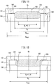
- FIG. 11 is a cross-sectional view in the sheet thickness direction explaining the range of plating removed when confirming cracking at the contact surface sides of the steel sheets with the electrodes and the mated surfaces of the steel sheets in two sheets combination.
- FIG. 11 shows by broken lines the scheduled location 102 of nugget formation, the scheduled location 103 of corona bond formation, the location 105 where cracking right below an electrode is predicted, the location 106 where cracking at an electrode shoulder is predicted, and the location 107 where cracking outside an electrode is predicted.
- FIG. 11 also shows the scheduled position 104 of formation of the outer edge of a heat affected zone by dotted lines.
- the range of removal of plating for prevention of external cracking is made the inside of a circle of the diameter D HAZ1 with an outer circumference of the outer edge of the heat affected zone.
- the scheduled position of formation of the outer edge of a heat affected zone of a steel sheet is a position where the steel sheet is heated to about 700°C. Therefore, in the welding process, the plating metal in this range melts and has sufficient liquidity. Therefore, even if removing the plating at only the portions where cracking occurs in order to prevent the external cracking, the surrounding plating becomes wet and spreads to the portions from which plating has been removed and the effect of removal of the plating is lost.
- the range for removing the plating may also be larger than the inside of a circle of the diameter D HAZ1 , that is, for example, the inside of a circle having a diameter of D HAZ1 x 1.5.
- the corrosion resistance decreases, so it should be as narrow as possible.
- positions at the outer edge of the heat affected zone differ in distance from the nugget center Cn in the sheet thickness direction. This is because the sides where the steel sheets and electrodes contact are cooled by the electrodes, while such a cooling action does not act at the mated surfaces.
- the diameter D HAZ1 of the range of removal of plating to prevent external cracking is preferably determined by the outer edge of the heat affected zone in the vicinity of the electrode side surfaces of the steel sheets.
- Nital or another corrosive liquid may be used to observe the cross-section of the test spot weld zone.
- the range of removal of plating is made the range at the mated surfaces of the steel sheets to be welded inside a circle with an outer circumference of a diameter of the broader outer edge of the weld heat affected zone of the mated surfaces of D HAZ2 .
- the range of removal of plating may also be made the range of the inside of a ring with an outer circumference of the broader outer edge of the weld heat affected zones formed at the mated surfaces of the superposed steel sheets and with an inner circumference of a circle sharing a center with a scheduled position becoming the center of the nugget formed at the mated surfaces of the steel sheets and having a diameter of 0.8 time the nugget diameter. This is because the plating inside the circle having a diameter of 0.8 time of the nugget diameter does not substantially contribute to the internal cracking.
- FIG. 11 is a cross-sectional view in the sheet thickness direction explaining the range of plating removed when confirming cracking at mated surfaces of the steel sheets in two sheets combination.
- FIG. 11 shows by broken lines the scheduled location 102 of nugget formation, the scheduled location 103 of corona bond formation, and the location 108 where cracking is predicted right outside the corona bond at the steel sheets 101 welded superposed.
- FIG. 12 shows by broken lines a location 109 where occurrence of cracking at the nugget boundary of the corona bond is predicted and a location 110 where occurrence of cracking inside the nugget is predicted.
- the cracking right outside the corona bond is caused by the molten plating metal melted at the scheduled location of corona bond formation and ejected by pressing by the electrodes and the molten plating metal at the inside of the heat affected zone and outside of the corona bond being wet right outside the corona bond and the action of tensile stress in that state.
- the cracking inside the corona bond and cracking at the nugget boundary of the corona bond is caused by the molten plating metal melted near the outer edge of the scheduled position of nugget formation and ejected by pressing by the electrodes and the molten plating metal at the scheduled location of corona bond formation being sealed inside the corona bond and the action of tensile stress in that state.
- the plating has to be removed not only near the position of occurrence of internal cracking, but also at the heat affected zone at the outside from the nugget center and a range including the scheduled position of nugget formation near the nugget center.
- the "molten plating metal” of course also includes plating metal which liquefies after evaporation and vaporization.
- the range of the plating to be removed is made the mated surfaces of the steel sheets to be welded in a range of the inside of a circle with an outer circumference of a circle equivalent diameter D HAZ2 of the broader outer edge of the heat affected zone of the mated surfaces and centered on the center Cn of the scheduled location 102 of nugget formation.
- the "circle equivalent diameter of an outer edge of a weld heat affected zone” is the diameter of a circle of the same area as the area of the broader outer edge of the heat affected zone at the mated surfaces of two superposed steel sheets.
- the plating has to be removed from both the plating of the superposed steel sheets. This is because if superposing plated steel sheets, even if removing just the plating of the cracked steel sheet, molten plating metal will be supplied from the other superposed steel sheet. By removing the plating of this range of plating in this way, several cracking factors become superposed. Even if a strong tensile stress occurs at the mated surfaces of the steel sheets, there is no molten plating metal present, so no internal cracking occurs.
- the range of removal of the plating may be made a range of the inside of a ring with an outer circumference of a circle centered at the center Cn of the scheduled location 102 of nugget formation and having a diameter of D HAZ2 or D HAZ3 and with an inner circumference of a circle centered at the center Cn of the scheduled location 102 of nugget formation formed at the mated surfaces of the steel sheets and having a diameter of a diameter 0.8 time the nugget Dn formed at the mated surfaces. This is because the plating inside the circle with a diameter 0.8 time the nugget does not substantially contribute to internal cracking.
- the plating metal covered at the outside of a circle of 0.8 time the circle equivalent diameter Dn of the scheduled location of nugget formation is in large part ejected into the corona bond in the welding process. Therefore, in order to suppress internal cracking, it is necessarily to reliably remove the plating covered in this range.
- the plating metal covered inside of the circle of 0.8 time the circle equivalent diameter Dn of the scheduled location of nugget formation is in small part discharged in the corona bond, so need not be proactively removed.
- the plating covering a range exceeding the circle equivalent diameter D HAZ2 or D HZ3 of the scheduled location of formation of the outer edge of the heat affected zone may also be removed considering the positional accuracy of the spot welding, but the corrosion resistance would fall, so in the case of removal, an effort should be made to improve the positional accuracy of the spot welding and the range made all of the part of 5.0 times or less the circle equivalent diameter D HAZ2 or D HAZ3 of the scheduled location of formation of the outer edge of the heat affected zone.
- the plating to be removed can be made all of the part of 2.0 times or less the circle equivalent diameter D HAZ2 or D HAZ3 , more preferably 1.5 times or less.
- the equivalent circle diameters D HAZ2 and D HAZ3 of the scheduled location of formation of the outer edge of the heat affected zone and circle equivalent diameter Dn of scheduled location of nugget formation are circle equivalent diameters observed at the time of determining the welding conditions by coupons (test pieces) before spot welding the plurality of steel sheets.
- the weld lengths are not necessarily all the same, but if the range of removal of plating of the welding method of the present invention, it is possible to sufficiently cover error in this.
- the current value is adjusted so that the nugget diameter becomes the same as the time of test spot welding. Due to this, it is possible to secure the strength of the spot welded joint originally targeted.
- the corrosion resistance of the welded locations of the steel sheets and electrodes and the mated surfaces of the steel sheets may become insufficient. Therefore, when removing the plating of the scheduled locations of contact of the steel sheets and the welding electrodes, after spot welding, preferably part or all of the parts from which plating is removed are coated with a sealer, while when removing the plating of the mated surfaces of the steel sheets, before spot welding, preferably part or all of the parts from which plating is removed is coated with a sealer or adhesive.
- the sealer or adhesive is not particularly limited. A known one used in assembly of car bodies may be used. Further, mixing metal particles made of zinc etc. with the sealer or adhesive in advance is also effective in securing the corrosion resistance.
- the method of removing the plating may employ at least one of mechanical removal and removal by evaporation.
- mechanical removal a rotating tool can be used to grind away the plating.
- the center of rotation is determined and the plating can be precisely removed.
- Removal by evaporation is the method of firing a laser beam having a circular shape, ring shape, square shape, or other focused shaped exceeding the range which must be removed so as to remove plating by evaporation. According to this, it is possible to selectively remove zinc, magnesium, and other low-boiling metals that cause liquid metal embrittlement.
- the laser beam In firing the laser beam, it is important to fire it at an angle so that the reflected beam does not return to the oscillator. From the viewpoint of environmental protection, it is preferable to provide a device for sucking in the vaporized metal. Further, the laser beam focused to tens of ⁇ m may be used to remove the plating by ablation. Further, by firing plasma, the plating can be removed by evaporation.
- the conditions in the examples are illustrations of conditions employed for confirming the workability and effects of the present invention.
- the present invention is not limited to these illustrations of conditions.
- the present invention may employ various conditions so long as not deviating from the gist of the present invention and achieving the object of the present invention.
- Table 1 shows the steel sheets used.
- the galvanized steel sheets A to E are galvannealed steel sheets covered at both surfaces with galvanization.
- Table 1 Steel type C content (mass%)
- Tensile strength (MPa) Sheet thickness (mm)
- Galvanized plating deposition (g/m 2 ) Galvanized steel sheet A 0.20 1200 1.6 50 Galvanized steel sheet B 0.24 980 1.6 55 Cold-rolled steel sheet 0.18 1200 1.6 None Galvanized steel sheet C 0.22 1200 1.0 50 Galvanized steel sheet D 0.003 270 1.0 50 Galvanized steel sheet E 0.16 440 1.0 50
- Test No. 1 is a comparative example of spot welding without removing the galvanization in a state where the axial center of the welding electrode is 3° from perpendicular to the surface of the steel sheet.
- the spot welding was performed from both sides by using dome radius-type electrodes with front end diameters of 6 mm to sandwich two steel sheets and press against them by a pressing force of 4 kN and by welding by a current-carrying time of 18 cycles and a current-carrying current of 9 kA.
- a current-carrying time of 18 cycles and a current-carrying current of 9 kA.
- Test Nos. 2 to 6 are examples of removing the galvanization for spot welding in view of the results of Test No. 1.
- Test No. 7 is a comparative example using an angled electrode with an axial center of 5° from perpendicular to the surface of a steel sheet during welding to spot weld the sheets without removing the galvanization in the state of a gap of the mated surfaces of 0.5 mm. In Test No. 7, internal cracking right outside the corona bond was confirmed.
- Test No. 8 is an example of removing the galvanization for spot welding in view of the results of Test No. 7.
- Test No. 9 is a comparative example of spot welding a combination of steel sheets with a large strength ratio without removing the galvanization. In Test No. 9, internal cracking was observed at the nugget boundary inside the corona bond.
- Test Nos. 10 to 12 are examples of removing the galvanization for spot welding in view of the results of Test No. 9.
- Test No. 13 is a comparative example of spot welding without removing the galvanization in the state with the axial centers of the facing welding electrodes being relatively misaligned by 0.5 mm and in the state with the fixed side welding electrode being positioned 0.2 mm from a steel sheet in the pressing direction.
- Test No. 13 internal cracking advancing from inside the corona bond to inside the nugget was confirmed.
- Test Nos. 14 to 17 are examples of removing the galvanization for spot welding in view of the results of Test No. 9.
- Test No. 18 is a comparative example using a welding gun with an axial center bent 3° from perpendicular with respect to the surface of the steel sheet and spot welding without removing the galvanization. In Test No. 18, external cracking was confirmed right below the electrode and at the shoulder.
- Test Nos. 19 to 20 are examples of removing the galvanization for spot welding in view of the results of Test No. 18.
- Test No. 21 is a comparative example using a welding gun bent so that its axial center becomes 3° from perpendicular to the surface of a steel sheet during welding and, further, spot welding a welded location having a gap of the mated surfaces of 0.5 mm or more without removing the galvanization. In Test No. 21, external cracking was confirmed outside of the electrode.
- the galvanization was heated by laser or plasma.
- a laser focused to a diameter of 9.5 mm was fired at the galvanization by an output of 1 kW for 0.1 second to remove the galvanization in the removal range.
- a laser focused to a diameter of 40 ⁇ m was fired at the galvanization by an average output of 9W, a number of repetitions of 50 kHz, a pulse width (time emitting the laser) of 20 ns, 10 shots at the same point and the entire area of the removal range was scanned to remove the galvanization.
- discharge was caused by a current of 200A and a voltage of 20V to heat the galvanization for 0.2 second.
- the plasma had a distribution of energy density, so the targeted range of galvanization was completely removed and the surroundings were also partially removed.
- the test piece was subjected to a combined cycle corrosion test (CCT test) to confirm the corrosion resistance and checked for cracks at the welded location.
- CCT test combined cycle corrosion test
- Tables 2 to 4 Note that letters for the cracking factors in Tables 2 to 4 correspond to the cases where the above-mentioned test spot welding is preferably performed (cracking factors).
- the CCT test was performed based on the corrosion testing method for automobiles (JASO M609-91) by repeatedly treating the test piece for 8 hours per cycle for 30 cycles.
- One cycle consisted of a salt spray test (2 hours, 5% NaCl, 35°C), drying (4 hours, 30% RH, 60°C), and a wetting test (2 hours, 95% RH, 50°C).
- the spot weld was evaluated as "Very Good” when no changes could be seen around the spot weld zone between the steel sheets, "Good” when white rust could be observed, and "Poor” when red rust formed. Further, cracking was checked by cutting a test piece in the sheet thickness direction to include the nugget and observing the cross-section.
- Test Nos. 2 to 3, 8, 10, 14 to 15, 19 to 20, and 22 to 23 removed the galvanization in the range defined in the present invention and then spot welded the sheets. As a result, no cracks formed at the weld and the corrosion resistance was good.
- Test No. 2 the location from which the galvanization was removed was coated with an adhesive.
- Test No. 20 the part from which the plating was removed was coated with a sealer after welding. Therefore, particularly good corrosion resistance was exhibited.
- Test Nos. 4 to 6 removed the galvanization, but the removal range was narrow and internal cracking occurred right outside the corona bond.
- Test Nos. 11 to 12 removed the galvanization, but the removal range was narrow and internal cracking advancing from the corona bond to the nugget boundary was formed.
- Test Nos. 16 to 17 removed the galvanization, but the removal zone was narrow and internal cracking advancing from the corona bond to the inside of the nugget occurred.
- Table 2 Test number Class Set of sheets Plating removal method Removal range
- Adhesive/ sealer CCT test results Cracking Cracking position Cracking factor 1 Comp. ex. Steel type A, 2 sheets superposed - - None Very Good Yes Internal cracking right outside corona bond a 2 Inv. ex. Ditto Laser Plating layers on both sides of mated surfaces, inside circle with outer circumference formed by outer edge of heat affected zone Adhesive Very Good None - a 3 Inv. ex.
- Ditto Laser Plating layers on both sides of mated surfaces inside ring with inner circumference at least 0.8 time nugget diameter and outer circumference formed by outer edge of heat affected zone None Good None - a 4 Comp. ex.
- Ditto Laser Plating layers on both sides of mated surfaces inside ring with inner circumference at least 0.9 time nugget diameter and outer circumference formed by outer edge of heat affected zone Adhesive Very Good Yes Internal cracking right outside corona bond a 5 Comp. ex.
- Ditto Laser Plating layers on both sides of mated surfaces Inside ring with inner circumference having diameter of at least 0.8 time nugget diameter and with outer circumference having diameter of 0.9 time diameter of outer edge of heat affected zone.
- Ditto Laser Plating layers on both sides of mated surfaces Inside cylindrical tube with inner circumference of diameter of at least 0.6 time nugget diameter and with outer circumference of diameter of 1.1 times diameter of outer edge of heat affected zone. Yes Very Good None - d, f 15 Inv. ex. Ditto Laser Plating layers on both sides of mated surfaces. Inside cylindrical tube with inner circumference of diameter of at least 0.8 time nugget diameter and with outer circumference of diameter of outer edge of heat affected zone None Good nothing - d, f 16 Comp. ex. Ditto Laser Plating layer on both sides of mated surfaces. Inside cylindrical tube with inner circumference of diameter of at least 0.9 time nugget diameter and with outer circumference of diameter of outer edge of heat affected zone.
- Ditto Laser ablation Galvanized layer in contact with electrode inside circle with outer circumference of outer edge of heat affected zone. None Good None - c 20 Inv. ex. Ditto Laser ablation Galvanized layer in contact with electrode, inside circle with outer circumference of outer edge of heat affected zone. Welding plating removal part, then coating sealer Very Good None - c 21 Comp. ex. Ditto - None Very Good Yes Cracking at outside of electrode c, e 22 Inv. ex. Ditto Grinding Galvanized layer in contact with electrode, inside circle with outer circumference of outer edge of heat affected zone. None Good nothing - c, e 23 Comp. ex. Ditto Grinding Galvanized layer in contact with electrode, inside circle with outer circumference of diameter of 0.9 time diameter of outer edge of heat affected zone. None Good Yes Cracking at outside of electrode c, e
- the present invention in spot welding, it is possible to simply prevent the occurrence of liquid metal embrittlement cracking. Accordingly, the present invention is high in industrial applicability.
Landscapes
- Engineering & Computer Science (AREA)
- Mechanical Engineering (AREA)
- Physics & Mathematics (AREA)
- Optics & Photonics (AREA)
- Plasma & Fusion (AREA)
- Resistance Welding (AREA)
Applications Claiming Priority (4)
| Application Number | Priority Date | Filing Date | Title |
|---|---|---|---|
| JP2015069553 | 2015-03-30 | ||
| JP2016022066 | 2016-02-08 | ||
| JP2016048893 | 2016-03-11 | ||
| PCT/JP2016/060541 WO2016159169A1 (ja) | 2015-03-30 | 2016-03-30 | めっき鋼板のスポット溶接方法 |
Publications (3)
| Publication Number | Publication Date |
|---|---|
| EP3278917A1 true EP3278917A1 (de) | 2018-02-07 |
| EP3278917A4 EP3278917A4 (de) | 2018-12-05 |
| EP3278917B1 EP3278917B1 (de) | 2020-12-16 |
Family
ID=57006878
Family Applications (1)
| Application Number | Title | Priority Date | Filing Date |
|---|---|---|---|
| EP16773050.6A Active EP3278917B1 (de) | 2015-03-30 | 2016-03-30 | Verfahren zum punktschweissen eines plattierten stahlblechs |
Country Status (12)
| Country | Link |
|---|---|
| US (1) | US10350701B2 (de) |
| EP (1) | EP3278917B1 (de) |
| JP (1) | JP6108049B2 (de) |
| KR (1) | KR101901085B1 (de) |
| CN (1) | CN107530820B (de) |
| BR (1) | BR112017020590A2 (de) |
| CA (1) | CA2980692C (de) |
| MX (1) | MX366087B (de) |
| MY (1) | MY186160A (de) |
| RU (1) | RU2685928C2 (de) |
| TW (1) | TWI628022B (de) |
| WO (1) | WO2016159169A1 (de) |
Cited By (2)
| Publication number | Priority date | Publication date | Assignee | Title |
|---|---|---|---|---|
| EP4484044A4 (de) * | 2022-06-03 | 2025-07-02 | Jfe Steel Corp | Schweissverbindung, schweisselement, verfahren zur herstellung davon und verfahren zum widerstandspunktschweissen |
| EP4484045A4 (de) * | 2022-06-03 | 2025-07-02 | Jfe Steel Corp | Schweissverbindung, schweisselement und herstellungsverfahren dafür sowie widerstandspunktschweissverfahren |
Families Citing this family (26)
| Publication number | Priority date | Publication date | Assignee | Title |
|---|---|---|---|---|
| US10946470B2 (en) * | 2015-12-16 | 2021-03-16 | Jfe Steel Corporation | Resistance spot welding method and welded member production method |
| WO2017135432A1 (ja) * | 2016-02-05 | 2017-08-10 | 新日鐵住金株式会社 | 破断予測方法及び装置、並びにプログラム及び記録媒体 |
| WO2018115946A1 (en) * | 2016-12-21 | 2018-06-28 | Arcelormittal | A method for the manufacture of a coated steel sheet |
| WO2018117459A1 (ko) * | 2016-12-22 | 2018-06-28 | 주식회사 포스코 | 고강도 아연도금 강판의 점 용접 방법 |
| CN108311787A (zh) * | 2018-01-18 | 2018-07-24 | 上海业识科技有限公司 | 基于连续激光、准连续激光的不锈钢面板表面焊接工艺 |
| US20190314915A1 (en) * | 2018-04-13 | 2019-10-17 | GM Global Technology Operations LLC | Resistance Spot Welding Workpiece Stack-Ups Having Steel Workpieces With Surface Coatings |
| JP7144225B2 (ja) * | 2018-07-19 | 2022-09-29 | 株式会社神戸製鋼所 | スポット溶接部の検査方法 |
| US20200114459A1 (en) * | 2018-10-15 | 2020-04-16 | GM Global Technology Operations LLC | Quality welding of similar and dissimilar metal welds with space between workpieces |
| US11065711B2 (en) * | 2018-11-02 | 2021-07-20 | GM Global Technology Operations LLC | High aspect ratio weld face design for dissimilar metal welding |
| WO2020096271A1 (en) * | 2018-11-08 | 2020-05-14 | Renault-Samsung Motors Co., Ltd. | Combination structure of metal sheets for automobile by using trip steel and method for manufacturing the same |
| JP2020082104A (ja) * | 2018-11-19 | 2020-06-04 | 株式会社神戸製鋼所 | 接合構造体及び接合構造体の製造方法 |
| KR102514674B1 (ko) | 2018-12-21 | 2023-03-27 | 제이에프이 스틸 가부시키가이샤 | 스폿 용접 부재 |
| JP7059979B2 (ja) * | 2019-04-25 | 2022-04-26 | Jfeスチール株式会社 | スポット溶接部材 |
| US11548091B2 (en) | 2019-10-10 | 2023-01-10 | GM Global Technology Operations LLC | Pretreatment of weld flanges to mitigate liquid metal embrittlement cracking in resistance welding of galvanized steels |
| KR20220121883A (ko) * | 2020-02-25 | 2022-09-01 | 가부시키가이샤 고베 세이코쇼 | 저항 스폿 용접 방법 |
| JP7152439B2 (ja) * | 2020-03-30 | 2022-10-12 | フタバ産業株式会社 | 接合部材の製造方法 |
| JP7208193B2 (ja) * | 2020-07-08 | 2023-01-18 | フタバ産業株式会社 | 抵抗スポット溶接方法及び抵抗スポット溶接装置 |
| JP7132300B2 (ja) * | 2020-09-18 | 2022-09-06 | フタバ産業株式会社 | 抵抗スポット溶接方法及び抵抗スポット溶接装置 |
| EP4332251B1 (de) * | 2021-04-27 | 2025-04-09 | Nippon Steel Corporation | Geschweisstes stahlelement |
| CN113275724A (zh) * | 2021-05-28 | 2021-08-20 | 天津津荣天宇精密机械股份有限公司 | 一种镀锌板电阻点焊方法及焊接装置 |
| JP7364113B2 (ja) | 2021-11-02 | 2023-10-18 | Jfeスチール株式会社 | 抵抗スポット溶接部材およびその抵抗スポット溶接方法 |
| WO2023107907A1 (en) * | 2021-12-06 | 2023-06-15 | Arconic Technologies Llc | Methods for resistance spot welding, resistance spot welding systems and apparatus, and parts formed using resistance spot welding |
| WO2023233704A1 (ja) | 2022-06-03 | 2023-12-07 | Jfeスチール株式会社 | 溶接継手、溶接部材およびその製造方法、ならびに、抵抗スポット溶接方法 |
| WO2023233705A1 (ja) | 2022-06-03 | 2023-12-07 | Jfeスチール株式会社 | 溶接継手、溶接部材およびその製造方法、ならびに、抵抗スポット溶接方法 |
| CN115213579B (zh) * | 2022-06-22 | 2024-08-13 | 首钢集团有限公司 | 一种镀层钢板焊点表面凸点的控制方法及装置 |
| JPWO2024241645A1 (de) | 2023-05-19 | 2024-11-28 |
Family Cites Families (33)
| Publication number | Priority date | Publication date | Assignee | Title |
|---|---|---|---|---|
| DE1814801A1 (de) * | 1966-09-21 | 1970-09-17 | Becker Dr Otto Alfred | Verfahren zum Widerstandsschweissen und -Loeten von beschichteten Blechen und Maschinen dazu |
| NL7101684A (de) | 1970-03-10 | 1971-09-14 | ||
| JPS5536051A (en) * | 1978-09-05 | 1980-03-13 | Kobe Steel Ltd | Resistance welding method of surface treated material |
| JPS55139190A (en) * | 1979-04-13 | 1980-10-30 | Mazda Motor Corp | Seam welding equipment of mild metal plated steel plate |
| JPS6343775A (ja) * | 1986-08-07 | 1988-02-24 | Toyota Motor Corp | メツキ鋼板のスポツト溶接方法 |
| US5047608A (en) * | 1989-02-23 | 1991-09-10 | Nippon Steel Corporation | Method and apparatus for resistance welding wherein the electrode axis is included with respect to the electrode forcing axis |
| JP2881273B2 (ja) | 1992-03-31 | 1999-04-12 | 日新製鋼株式会社 | 表面処理鋼管の製造方法 |
| RU2066264C1 (ru) * | 1992-12-14 | 1996-09-10 | Волжское объединение по производству легковых автомобилей "АвтоВАЗ" | Способ контактной точечной сварки оцинкованных стальных листов |
| JP2638413B2 (ja) * | 1993-01-11 | 1997-08-06 | 菊池プレス工業株式会社 | 抵抗溶接方法 |
| GB2274257A (en) | 1993-01-19 | 1994-07-20 | British Aerospace | Method of preparing and welding zinc coated steel |
| JPH10143212A (ja) | 1996-11-08 | 1998-05-29 | Nissan Motor Co Ltd | 溶接電極の面直検出方法 |
| JP2000271758A (ja) * | 1999-03-26 | 2000-10-03 | Kyushu Fukugo Zairyo Kenkyusho:Kk | チタン板と鋼板のシーム溶接方法 |
| JP2003089881A (ja) | 2001-09-17 | 2003-03-28 | Sumitomo Metal Ind Ltd | 無機潤滑皮膜を有する亜鉛系めっき鋼板とその製造方法 |
| RU2243071C2 (ru) * | 2002-07-01 | 2004-12-27 | Открытое акционерное общество "АВТОВАЗ" | Способ контактной точечной сварки оцинкованных стальных листов |
| JP4262050B2 (ja) * | 2002-11-27 | 2009-05-13 | 株式会社ダイヘン | 抵抗溶接制御方法 |
| JP4854920B2 (ja) * | 2003-08-29 | 2012-01-18 | 豊田鉄工株式会社 | スポット溶接方法およびスポット溶接された鋼板部材 |
| JP2005088029A (ja) * | 2003-09-16 | 2005-04-07 | Nissan Motor Co Ltd | 亜鉛めっき鋼板のスポット溶接方法および装置 |
| JP2006265671A (ja) | 2005-03-25 | 2006-10-05 | Nisshin Steel Co Ltd | 加工性及び耐溶融金属脆化割れ性に優れた合金化溶融亜鉛めっき高張力鋼板 |
| JP4791992B2 (ja) | 2007-03-20 | 2011-10-12 | 日新製鋼株式会社 | スポット溶接用合金化溶融亜鉛めっき鋼板の製造方法 |
| KR101277778B1 (ko) * | 2008-12-03 | 2013-06-24 | 신닛테츠스미킨 카부시키카이샤 | 도장 금속재 및 그 제조 방법 |
| CN101961814A (zh) * | 2009-07-24 | 2011-02-02 | 宝山钢铁股份有限公司 | 一种热镀铝锌钢板的点焊方法 |
| EP2460613A4 (de) * | 2009-07-31 | 2015-11-04 | Neturen Co Ltd | Geschweisstes bauelement und schweissverfahren |
| JP5531743B2 (ja) | 2010-04-12 | 2014-06-25 | 新日鐵住金株式会社 | レーザろう付け方法 |
| CN101985189A (zh) * | 2010-10-26 | 2011-03-16 | 聂健 | 汽车金属燃油箱的表盘双脉冲凸点焊工艺方法 |
| JP2013063460A (ja) | 2011-09-20 | 2013-04-11 | Nippon Steel & Sumikin Welding Co Ltd | 亜鉛系めっき鋼板の重ね継手アークスポット溶接方法 |
| US10543562B2 (en) * | 2012-08-10 | 2020-01-28 | Nippon Steel Corporation | Overlap-welded member, automobile part, method of welding overlapped portion, and method of manufacturing overlap-welded member |
| KR101714293B1 (ko) | 2013-03-08 | 2017-03-08 | 제이에프이 스틸 가부시키가이샤 | 저항 스폿 용접 방법 |
| JP6001478B2 (ja) * | 2013-03-19 | 2016-10-05 | 株式会社神戸製鋼所 | スポット溶接継手 |
| JP6107939B2 (ja) * | 2013-04-17 | 2017-04-05 | 新日鐵住金株式会社 | スポット溶接方法 |
| KR101325871B1 (ko) * | 2013-05-13 | 2013-11-05 | 현대하이스코 주식회사 | 핫 스탬핑 부품 용접성 개선방법 |
| CN203265868U (zh) * | 2013-05-27 | 2013-11-06 | 武汉钢铁(集团)公司 | 一种能清理涂镀层钢板表层的点焊机 |
| DE112014005891T5 (de) * | 2014-01-20 | 2016-09-22 | GM Global Technology Operations LLC | Schweissverfahren und Schweisssystem |
| CN104084686B (zh) * | 2014-06-12 | 2017-01-18 | 上海翼锐汽车科技有限公司 | 一种用于抑制铝合金电阻点焊裂纹产生的电极 |
-
2016
- 2016-03-30 MX MX2017012458A patent/MX366087B/es active IP Right Grant
- 2016-03-30 WO PCT/JP2016/060541 patent/WO2016159169A1/ja not_active Ceased
- 2016-03-30 KR KR1020177026773A patent/KR101901085B1/ko active Active
- 2016-03-30 BR BR112017020590A patent/BR112017020590A2/pt active Search and Examination
- 2016-03-30 JP JP2016562041A patent/JP6108049B2/ja active Active
- 2016-03-30 RU RU2017135023A patent/RU2685928C2/ru not_active IP Right Cessation
- 2016-03-30 US US15/563,489 patent/US10350701B2/en active Active
- 2016-03-30 MY MYPI2017703520A patent/MY186160A/en unknown
- 2016-03-30 EP EP16773050.6A patent/EP3278917B1/de active Active
- 2016-03-30 CA CA2980692A patent/CA2980692C/en not_active Expired - Fee Related
- 2016-03-30 CN CN201680020469.9A patent/CN107530820B/zh active Active
- 2016-03-30 TW TW105110065A patent/TWI628022B/zh not_active IP Right Cessation
Cited By (2)
| Publication number | Priority date | Publication date | Assignee | Title |
|---|---|---|---|---|
| EP4484044A4 (de) * | 2022-06-03 | 2025-07-02 | Jfe Steel Corp | Schweissverbindung, schweisselement, verfahren zur herstellung davon und verfahren zum widerstandspunktschweissen |
| EP4484045A4 (de) * | 2022-06-03 | 2025-07-02 | Jfe Steel Corp | Schweissverbindung, schweisselement und herstellungsverfahren dafür sowie widerstandspunktschweissverfahren |
Also Published As
| Publication number | Publication date |
|---|---|
| MX366087B (es) | 2019-06-27 |
| JPWO2016159169A1 (ja) | 2017-04-27 |
| EP3278917A4 (de) | 2018-12-05 |
| WO2016159169A1 (ja) | 2016-10-06 |
| US20180079026A1 (en) | 2018-03-22 |
| TWI628022B (zh) | 2018-07-01 |
| CA2980692A1 (en) | 2016-10-06 |
| BR112017020590A2 (pt) | 2018-07-03 |
| RU2017135023A3 (de) | 2019-04-05 |
| MY186160A (en) | 2021-06-30 |
| KR101901085B1 (ko) | 2018-09-20 |
| MX2017012458A (es) | 2018-01-30 |
| KR20170113689A (ko) | 2017-10-12 |
| US10350701B2 (en) | 2019-07-16 |
| JP6108049B2 (ja) | 2017-04-05 |
| RU2017135023A (ru) | 2019-04-05 |
| RU2685928C2 (ru) | 2019-04-23 |
| EP3278917B1 (de) | 2020-12-16 |
| CN107530820A (zh) | 2018-01-02 |
| CN107530820B (zh) | 2019-04-19 |
| TW201641201A (zh) | 2016-12-01 |
| CA2980692C (en) | 2018-04-24 |
Similar Documents
| Publication | Publication Date | Title |
|---|---|---|
| EP3278917B1 (de) | Verfahren zum punktschweissen eines plattierten stahlblechs | |
| JP6108018B2 (ja) | スポット溶接方法 | |
| JP6108017B2 (ja) | スポット溶接方法 | |
| US10052721B2 (en) | Method of laser welding coated steel sheets with addition of alloying elements | |
| TWI642506B (zh) | Point welding method | |
| CN108025387B (zh) | 点焊方法 | |
| CN113195145B (zh) | 点焊部件 | |
| JP6780386B2 (ja) | スポット溶接方法 | |
| KR102061471B1 (ko) | 레이저 브레이징 방법 및 겹치기 이음 부재의 제조방법 | |
| US11548091B2 (en) | Pretreatment of weld flanges to mitigate liquid metal embrittlement cracking in resistance welding of galvanized steels | |
| US20240123539A1 (en) | Resistance spot welded joint and method for manufacturing resistance spot welded joint | |
| JP7477059B1 (ja) | 溶接部材およびその製造方法 | |
| WO2025121278A1 (ja) | 抵抗スポット溶接部材およびその抵抗スポット溶接方法 | |
| JP2025136232A (ja) | Al系めっき鋼板、Al系めっき鋼板の製造方法、及びテーラードブランクの製造方法 | |
| WO2025121277A1 (ja) | 抵抗スポット溶接部材およびその抵抗スポット溶接方法 |
Legal Events
| Date | Code | Title | Description |
|---|---|---|---|
| STAA | Information on the status of an ep patent application or granted ep patent |
Free format text: STATUS: THE INTERNATIONAL PUBLICATION HAS BEEN MADE |
|
| PUAI | Public reference made under article 153(3) epc to a published international application that has entered the european phase |
Free format text: ORIGINAL CODE: 0009012 |
|
| STAA | Information on the status of an ep patent application or granted ep patent |
Free format text: STATUS: REQUEST FOR EXAMINATION WAS MADE |
|
| 17P | Request for examination filed |
Effective date: 20171009 |
|
| AK | Designated contracting states |
Kind code of ref document: A1 Designated state(s): AL AT BE BG CH CY CZ DE DK EE ES FI FR GB GR HR HU IE IS IT LI LT LU LV MC MK MT NL NO PL PT RO RS SE SI SK SM TR |
|
| AX | Request for extension of the european patent |
Extension state: BA ME |
|
| DAV | Request for validation of the european patent (deleted) | ||
| DAX | Request for extension of the european patent (deleted) | ||
| A4 | Supplementary search report drawn up and despatched |
Effective date: 20181106 |
|
| RIC1 | Information provided on ipc code assigned before grant |
Ipc: B23K 11/34 20060101AFI20181029BHEP Ipc: B23K 26/36 20140101ALI20181029BHEP Ipc: B23K 11/11 20060101ALI20181029BHEP Ipc: B23K 11/16 20060101ALI20181029BHEP |
|
| RAP1 | Party data changed (applicant data changed or rights of an application transferred) |
Owner name: NIPPON STEEL CORPORATION |
|
| TPAC | Observations filed by third parties |
Free format text: ORIGINAL CODE: EPIDOSNTIPA |
|
| STAA | Information on the status of an ep patent application or granted ep patent |
Free format text: STATUS: EXAMINATION IS IN PROGRESS |
|
| 17Q | First examination report despatched |
Effective date: 20191030 |
|
| GRAP | Despatch of communication of intention to grant a patent |
Free format text: ORIGINAL CODE: EPIDOSNIGR1 |
|
| STAA | Information on the status of an ep patent application or granted ep patent |
Free format text: STATUS: GRANT OF PATENT IS INTENDED |
|
| INTG | Intention to grant announced |
Effective date: 20200630 |
|
| GRAS | Grant fee paid |
Free format text: ORIGINAL CODE: EPIDOSNIGR3 |
|
| GRAA | (expected) grant |
Free format text: ORIGINAL CODE: 0009210 |
|
| STAA | Information on the status of an ep patent application or granted ep patent |
Free format text: STATUS: THE PATENT HAS BEEN GRANTED |
|
| AK | Designated contracting states |
Kind code of ref document: B1 Designated state(s): AL AT BE BG CH CY CZ DE DK EE ES FI FR GB GR HR HU IE IS IT LI LT LU LV MC MK MT NL NO PL PT RO RS SE SI SK SM TR |
|
| REG | Reference to a national code |
Ref country code: GB Ref legal event code: FG4D |
|
| REG | Reference to a national code |
Ref country code: IE Ref legal event code: FG4D |
|
| REG | Reference to a national code |
Ref country code: DE Ref legal event code: R096 Ref document number: 602016049919 Country of ref document: DE |
|
| REG | Reference to a national code |
Ref country code: AT Ref legal event code: REF Ref document number: 1345145 Country of ref document: AT Kind code of ref document: T Effective date: 20210115 |
|
| PG25 | Lapsed in a contracting state [announced via postgrant information from national office to epo] |
Ref country code: RS Free format text: LAPSE BECAUSE OF FAILURE TO SUBMIT A TRANSLATION OF THE DESCRIPTION OR TO PAY THE FEE WITHIN THE PRESCRIBED TIME-LIMIT Effective date: 20201216 Ref country code: NO Free format text: LAPSE BECAUSE OF FAILURE TO SUBMIT A TRANSLATION OF THE DESCRIPTION OR TO PAY THE FEE WITHIN THE PRESCRIBED TIME-LIMIT Effective date: 20210316 Ref country code: FI Free format text: LAPSE BECAUSE OF FAILURE TO SUBMIT A TRANSLATION OF THE DESCRIPTION OR TO PAY THE FEE WITHIN THE PRESCRIBED TIME-LIMIT Effective date: 20201216 Ref country code: GR Free format text: LAPSE BECAUSE OF FAILURE TO SUBMIT A TRANSLATION OF THE DESCRIPTION OR TO PAY THE FEE WITHIN THE PRESCRIBED TIME-LIMIT Effective date: 20210317 |
|
| REG | Reference to a national code |
Ref country code: AT Ref legal event code: MK05 Ref document number: 1345145 Country of ref document: AT Kind code of ref document: T Effective date: 20201216 |
|
| REG | Reference to a national code |
Ref country code: NL Ref legal event code: MP Effective date: 20201216 |
|
| PG25 | Lapsed in a contracting state [announced via postgrant information from national office to epo] |
Ref country code: SE Free format text: LAPSE BECAUSE OF FAILURE TO SUBMIT A TRANSLATION OF THE DESCRIPTION OR TO PAY THE FEE WITHIN THE PRESCRIBED TIME-LIMIT Effective date: 20201216 Ref country code: BG Free format text: LAPSE BECAUSE OF FAILURE TO SUBMIT A TRANSLATION OF THE DESCRIPTION OR TO PAY THE FEE WITHIN THE PRESCRIBED TIME-LIMIT Effective date: 20210316 Ref country code: LV Free format text: LAPSE BECAUSE OF FAILURE TO SUBMIT A TRANSLATION OF THE DESCRIPTION OR TO PAY THE FEE WITHIN THE PRESCRIBED TIME-LIMIT Effective date: 20201216 |
|
| PG25 | Lapsed in a contracting state [announced via postgrant information from national office to epo] |
Ref country code: NL Free format text: LAPSE BECAUSE OF FAILURE TO SUBMIT A TRANSLATION OF THE DESCRIPTION OR TO PAY THE FEE WITHIN THE PRESCRIBED TIME-LIMIT Effective date: 20201216 Ref country code: HR Free format text: LAPSE BECAUSE OF FAILURE TO SUBMIT A TRANSLATION OF THE DESCRIPTION OR TO PAY THE FEE WITHIN THE PRESCRIBED TIME-LIMIT Effective date: 20201216 |
|
| REG | Reference to a national code |
Ref country code: LT Ref legal event code: MG9D |
|
| PG25 | Lapsed in a contracting state [announced via postgrant information from national office to epo] |
Ref country code: RO Free format text: LAPSE BECAUSE OF FAILURE TO SUBMIT A TRANSLATION OF THE DESCRIPTION OR TO PAY THE FEE WITHIN THE PRESCRIBED TIME-LIMIT Effective date: 20201216 Ref country code: PT Free format text: LAPSE BECAUSE OF FAILURE TO SUBMIT A TRANSLATION OF THE DESCRIPTION OR TO PAY THE FEE WITHIN THE PRESCRIBED TIME-LIMIT Effective date: 20210416 Ref country code: SK Free format text: LAPSE BECAUSE OF FAILURE TO SUBMIT A TRANSLATION OF THE DESCRIPTION OR TO PAY THE FEE WITHIN THE PRESCRIBED TIME-LIMIT Effective date: 20201216 Ref country code: SM Free format text: LAPSE BECAUSE OF FAILURE TO SUBMIT A TRANSLATION OF THE DESCRIPTION OR TO PAY THE FEE WITHIN THE PRESCRIBED TIME-LIMIT Effective date: 20201216 Ref country code: LT Free format text: LAPSE BECAUSE OF FAILURE TO SUBMIT A TRANSLATION OF THE DESCRIPTION OR TO PAY THE FEE WITHIN THE PRESCRIBED TIME-LIMIT Effective date: 20201216 Ref country code: EE Free format text: LAPSE BECAUSE OF FAILURE TO SUBMIT A TRANSLATION OF THE DESCRIPTION OR TO PAY THE FEE WITHIN THE PRESCRIBED TIME-LIMIT Effective date: 20201216 Ref country code: CZ Free format text: LAPSE BECAUSE OF FAILURE TO SUBMIT A TRANSLATION OF THE DESCRIPTION OR TO PAY THE FEE WITHIN THE PRESCRIBED TIME-LIMIT Effective date: 20201216 |
|
| PG25 | Lapsed in a contracting state [announced via postgrant information from national office to epo] |
Ref country code: AT Free format text: LAPSE BECAUSE OF FAILURE TO SUBMIT A TRANSLATION OF THE DESCRIPTION OR TO PAY THE FEE WITHIN THE PRESCRIBED TIME-LIMIT Effective date: 20201216 Ref country code: PL Free format text: LAPSE BECAUSE OF FAILURE TO SUBMIT A TRANSLATION OF THE DESCRIPTION OR TO PAY THE FEE WITHIN THE PRESCRIBED TIME-LIMIT Effective date: 20201216 |
|
| REG | Reference to a national code |
Ref country code: DE Ref legal event code: R026 Ref document number: 602016049919 Country of ref document: DE |
|
| PLBI | Opposition filed |
Free format text: ORIGINAL CODE: 0009260 |
|
| PLAB | Opposition data, opponent's data or that of the opponent's representative modified |
Free format text: ORIGINAL CODE: 0009299OPPO |
|
| PG25 | Lapsed in a contracting state [announced via postgrant information from national office to epo] |
Ref country code: IS Free format text: LAPSE BECAUSE OF FAILURE TO SUBMIT A TRANSLATION OF THE DESCRIPTION OR TO PAY THE FEE WITHIN THE PRESCRIBED TIME-LIMIT Effective date: 20210416 |
|
| PLAX | Notice of opposition and request to file observation + time limit sent |
Free format text: ORIGINAL CODE: EPIDOSNOBS2 |
|
| PLAB | Opposition data, opponent's data or that of the opponent's representative modified |
Free format text: ORIGINAL CODE: 0009299OPPO |
|
| 26 | Opposition filed |
Opponent name: ARCELORMITTAL FRANCE Effective date: 20210916 |
|
| R26 | Opposition filed (corrected) |
Opponent name: ARCELORMITTAL FRANCE Effective date: 20210916 |
|
| PG25 | Lapsed in a contracting state [announced via postgrant information from national office to epo] |
Ref country code: MC Free format text: LAPSE BECAUSE OF FAILURE TO SUBMIT A TRANSLATION OF THE DESCRIPTION OR TO PAY THE FEE WITHIN THE PRESCRIBED TIME-LIMIT Effective date: 20201216 Ref country code: IT Free format text: LAPSE BECAUSE OF FAILURE TO SUBMIT A TRANSLATION OF THE DESCRIPTION OR TO PAY THE FEE WITHIN THE PRESCRIBED TIME-LIMIT Effective date: 20201216 Ref country code: AL Free format text: LAPSE BECAUSE OF FAILURE TO SUBMIT A TRANSLATION OF THE DESCRIPTION OR TO PAY THE FEE WITHIN THE PRESCRIBED TIME-LIMIT Effective date: 20201216 |
|
| REG | Reference to a national code |
Ref country code: CH Ref legal event code: PL |
|
| R26 | Opposition filed (corrected) |
Opponent name: ARCELORMITTAL Effective date: 20210916 |
|
| GBPC | Gb: european patent ceased through non-payment of renewal fee |
Effective date: 20210330 |
|
| PG25 | Lapsed in a contracting state [announced via postgrant information from national office to epo] |
Ref country code: DK Free format text: LAPSE BECAUSE OF FAILURE TO SUBMIT A TRANSLATION OF THE DESCRIPTION OR TO PAY THE FEE WITHIN THE PRESCRIBED TIME-LIMIT Effective date: 20201216 |
|
| REG | Reference to a national code |
Ref country code: BE Ref legal event code: MM Effective date: 20210331 |
|
| PG25 | Lapsed in a contracting state [announced via postgrant information from national office to epo] |
Ref country code: IE Free format text: LAPSE BECAUSE OF NON-PAYMENT OF DUE FEES Effective date: 20210330 Ref country code: GB Free format text: LAPSE BECAUSE OF NON-PAYMENT OF DUE FEES Effective date: 20210330 Ref country code: ES Free format text: LAPSE BECAUSE OF FAILURE TO SUBMIT A TRANSLATION OF THE DESCRIPTION OR TO PAY THE FEE WITHIN THE PRESCRIBED TIME-LIMIT Effective date: 20201216 Ref country code: CH Free format text: LAPSE BECAUSE OF NON-PAYMENT OF DUE FEES Effective date: 20210331 Ref country code: LU Free format text: LAPSE BECAUSE OF NON-PAYMENT OF DUE FEES Effective date: 20210330 Ref country code: LI Free format text: LAPSE BECAUSE OF NON-PAYMENT OF DUE FEES Effective date: 20210331 |
|
| PLBB | Reply of patent proprietor to notice(s) of opposition received |
Free format text: ORIGINAL CODE: EPIDOSNOBS3 |
|
| PG25 | Lapsed in a contracting state [announced via postgrant information from national office to epo] |
Ref country code: SI Free format text: LAPSE BECAUSE OF FAILURE TO SUBMIT A TRANSLATION OF THE DESCRIPTION OR TO PAY THE FEE WITHIN THE PRESCRIBED TIME-LIMIT Effective date: 20201216 |
|
| PG25 | Lapsed in a contracting state [announced via postgrant information from national office to epo] |
Ref country code: IS Free format text: LAPSE BECAUSE OF FAILURE TO SUBMIT A TRANSLATION OF THE DESCRIPTION OR TO PAY THE FEE WITHIN THE PRESCRIBED TIME-LIMIT Effective date: 20210416 |
|
| PLAB | Opposition data, opponent's data or that of the opponent's representative modified |
Free format text: ORIGINAL CODE: 0009299OPPO |
|
| PG25 | Lapsed in a contracting state [announced via postgrant information from national office to epo] |
Ref country code: BE Free format text: LAPSE BECAUSE OF NON-PAYMENT OF DUE FEES Effective date: 20210331 |
|
| R26 | Opposition filed (corrected) |
Opponent name: ARCELORMITTAL Effective date: 20210916 |
|
| PG25 | Lapsed in a contracting state [announced via postgrant information from national office to epo] |
Ref country code: CY Free format text: LAPSE BECAUSE OF FAILURE TO SUBMIT A TRANSLATION OF THE DESCRIPTION OR TO PAY THE FEE WITHIN THE PRESCRIBED TIME-LIMIT Effective date: 20201216 |
|
| PG25 | Lapsed in a contracting state [announced via postgrant information from national office to epo] |
Ref country code: HU Free format text: LAPSE BECAUSE OF FAILURE TO SUBMIT A TRANSLATION OF THE DESCRIPTION OR TO PAY THE FEE WITHIN THE PRESCRIBED TIME-LIMIT; INVALID AB INITIO Effective date: 20160330 |
|
| APAH | Appeal reference modified |
Free format text: ORIGINAL CODE: EPIDOSCREFNO |
|
| APBM | Appeal reference recorded |
Free format text: ORIGINAL CODE: EPIDOSNREFNO |
|
| APBP | Date of receipt of notice of appeal recorded |
Free format text: ORIGINAL CODE: EPIDOSNNOA2O |
|
| APBQ | Date of receipt of statement of grounds of appeal recorded |
Free format text: ORIGINAL CODE: EPIDOSNNOA3O |
|
| PG25 | Lapsed in a contracting state [announced via postgrant information from national office to epo] |
Ref country code: MK Free format text: LAPSE BECAUSE OF FAILURE TO SUBMIT A TRANSLATION OF THE DESCRIPTION OR TO PAY THE FEE WITHIN THE PRESCRIBED TIME-LIMIT Effective date: 20201216 |
|
| PG25 | Lapsed in a contracting state [announced via postgrant information from national office to epo] |
Ref country code: TR Free format text: LAPSE BECAUSE OF FAILURE TO SUBMIT A TRANSLATION OF THE DESCRIPTION OR TO PAY THE FEE WITHIN THE PRESCRIBED TIME-LIMIT Effective date: 20201216 |
|
| PG25 | Lapsed in a contracting state [announced via postgrant information from national office to epo] |
Ref country code: MT Free format text: LAPSE BECAUSE OF FAILURE TO SUBMIT A TRANSLATION OF THE DESCRIPTION OR TO PAY THE FEE WITHIN THE PRESCRIBED TIME-LIMIT Effective date: 20201216 |
|
| PGFP | Annual fee paid to national office [announced via postgrant information from national office to epo] |
Ref country code: DE Payment date: 20250204 Year of fee payment: 10 |
|
| PGFP | Annual fee paid to national office [announced via postgrant information from national office to epo] |
Ref country code: FR Payment date: 20250210 Year of fee payment: 10 |
|
| APBU | Appeal procedure closed |
Free format text: ORIGINAL CODE: EPIDOSNNOA9O |