EP3246786A1 - Connector assembly for an electronic device - Google Patents
Connector assembly for an electronic device Download PDFInfo
- Publication number
- EP3246786A1 EP3246786A1 EP17177711.3A EP17177711A EP3246786A1 EP 3246786 A1 EP3246786 A1 EP 3246786A1 EP 17177711 A EP17177711 A EP 17177711A EP 3246786 A1 EP3246786 A1 EP 3246786A1
- Authority
- EP
- European Patent Office
- Prior art keywords
- electronic device
- barrel portion
- metallic
- keyboard
- assembly
- Prior art date
- Legal status (The legal status is an assumption and is not a legal conclusion. Google has not performed a legal analysis and makes no representation as to the accuracy of the status listed.)
- Pending
Links
- 230000007246 mechanism Effects 0.000 description 49
- 238000010586 diagram Methods 0.000 description 39
- CWYNVVGOOAEACU-UHFFFAOYSA-N Fe2+ Chemical compound [Fe+2] CWYNVVGOOAEACU-UHFFFAOYSA-N 0.000 description 19
- 238000013461 design Methods 0.000 description 17
- 238000000034 method Methods 0.000 description 12
- 238000003032 molecular docking Methods 0.000 description 10
- 230000006870 function Effects 0.000 description 8
- 238000005516 engineering process Methods 0.000 description 7
- 230000014759 maintenance of location Effects 0.000 description 7
- 230000036316 preload Effects 0.000 description 6
- 239000002344 surface layer Substances 0.000 description 6
- 229910000831 Steel Inorganic materials 0.000 description 5
- 238000004891 communication Methods 0.000 description 5
- 230000010354 integration Effects 0.000 description 5
- 239000010959 steel Substances 0.000 description 5
- 238000010276 construction Methods 0.000 description 4
- 229910052751 metal Inorganic materials 0.000 description 4
- 239000002184 metal Substances 0.000 description 4
- 238000012545 processing Methods 0.000 description 4
- 230000006835 compression Effects 0.000 description 3
- 238000007906 compression Methods 0.000 description 3
- 230000000694 effects Effects 0.000 description 3
- 238000003780 insertion Methods 0.000 description 3
- 230000037431 insertion Effects 0.000 description 3
- 230000003993 interaction Effects 0.000 description 3
- 238000012986 modification Methods 0.000 description 3
- 230000004048 modification Effects 0.000 description 3
- 230000037361 pathway Effects 0.000 description 3
- 239000004033 plastic Substances 0.000 description 3
- 229920003023 plastic Polymers 0.000 description 3
- 238000012546 transfer Methods 0.000 description 3
- 230000004075 alteration Effects 0.000 description 2
- 230000005540 biological transmission Effects 0.000 description 2
- 239000012212 insulator Substances 0.000 description 2
- 230000002093 peripheral effect Effects 0.000 description 2
- 238000000926 separation method Methods 0.000 description 2
- 238000006467 substitution reaction Methods 0.000 description 2
- 238000010897 surface acoustic wave method Methods 0.000 description 2
- 230000007704 transition Effects 0.000 description 2
- 229920002430 Fibre-reinforced plastic Polymers 0.000 description 1
- RTAQQCXQSZGOHL-UHFFFAOYSA-N Titanium Chemical compound [Ti] RTAQQCXQSZGOHL-UHFFFAOYSA-N 0.000 description 1
- 230000000712 assembly Effects 0.000 description 1
- 238000000429 assembly Methods 0.000 description 1
- 230000002457 bidirectional effect Effects 0.000 description 1
- 239000003990 capacitor Substances 0.000 description 1
- 230000008867 communication pathway Effects 0.000 description 1
- 239000004020 conductor Substances 0.000 description 1
- 230000008878 coupling Effects 0.000 description 1
- 238000010168 coupling process Methods 0.000 description 1
- 238000005859 coupling reaction Methods 0.000 description 1
- 239000011151 fibre-reinforced plastic Substances 0.000 description 1
- 239000011521 glass Substances 0.000 description 1
- 238000003331 infrared imaging Methods 0.000 description 1
- 238000002347 injection Methods 0.000 description 1
- 239000007924 injection Substances 0.000 description 1
- 239000004973 liquid crystal related substance Substances 0.000 description 1
- 239000000463 material Substances 0.000 description 1
- 230000013011 mating Effects 0.000 description 1
- 230000003278 mimic effect Effects 0.000 description 1
- 238000012634 optical imaging Methods 0.000 description 1
- 230000008569 process Effects 0.000 description 1
- APTZNLHMIGJTEW-UHFFFAOYSA-N pyraflufen-ethyl Chemical compound C1=C(Cl)C(OCC(=O)OCC)=CC(C=2C(=C(OC(F)F)N(C)N=2)Cl)=C1F APTZNLHMIGJTEW-UHFFFAOYSA-N 0.000 description 1
- 230000000284 resting effect Effects 0.000 description 1
- 230000000717 retained effect Effects 0.000 description 1
- 239000000243 solution Substances 0.000 description 1
- 239000000758 substrate Substances 0.000 description 1
- 239000010936 titanium Substances 0.000 description 1
- 229910052719 titanium Inorganic materials 0.000 description 1
Images


Classifications
-
- G—PHYSICS
- G06—COMPUTING; CALCULATING OR COUNTING
- G06F—ELECTRIC DIGITAL DATA PROCESSING
- G06F1/00—Details not covered by groups G06F3/00 - G06F13/00 and G06F21/00
- G06F1/16—Constructional details or arrangements
-
- G—PHYSICS
- G06—COMPUTING; CALCULATING OR COUNTING
- G06F—ELECTRIC DIGITAL DATA PROCESSING
- G06F1/00—Details not covered by groups G06F3/00 - G06F13/00 and G06F21/00
- G06F1/16—Constructional details or arrangements
- G06F1/1613—Constructional details or arrangements for portable computers
- G06F1/1633—Constructional details or arrangements of portable computers not specific to the type of enclosures covered by groups G06F1/1615 - G06F1/1626
- G06F1/1662—Details related to the integrated keyboard
- G06F1/1669—Detachable keyboards
-
- G—PHYSICS
- G06—COMPUTING; CALCULATING OR COUNTING
- G06F—ELECTRIC DIGITAL DATA PROCESSING
- G06F1/00—Details not covered by groups G06F3/00 - G06F13/00 and G06F21/00
- G06F1/16—Constructional details or arrangements
- G06F1/1613—Constructional details or arrangements for portable computers
- G06F1/1615—Constructional details or arrangements for portable computers with several enclosures having relative motions, each enclosure supporting at least one I/O or computing function
-
- E—FIXED CONSTRUCTIONS
- E05—LOCKS; KEYS; WINDOW OR DOOR FITTINGS; SAFES
- E05D—HINGES OR SUSPENSION DEVICES FOR DOORS, WINDOWS OR WINGS
- E05D7/00—Hinges or pivots of special construction
-
- G—PHYSICS
- G06—COMPUTING; CALCULATING OR COUNTING
- G06F—ELECTRIC DIGITAL DATA PROCESSING
- G06F1/00—Details not covered by groups G06F3/00 - G06F13/00 and G06F21/00
- G06F1/16—Constructional details or arrangements
- G06F1/1613—Constructional details or arrangements for portable computers
- G06F1/1615—Constructional details or arrangements for portable computers with several enclosures having relative motions, each enclosure supporting at least one I/O or computing function
- G06F1/1616—Constructional details or arrangements for portable computers with several enclosures having relative motions, each enclosure supporting at least one I/O or computing function with folding flat displays, e.g. laptop computers or notebooks having a clamshell configuration, with body parts pivoting to an open position around an axis parallel to the plane they define in closed position
-
- G—PHYSICS
- G06—COMPUTING; CALCULATING OR COUNTING
- G06F—ELECTRIC DIGITAL DATA PROCESSING
- G06F1/00—Details not covered by groups G06F3/00 - G06F13/00 and G06F21/00
- G06F1/16—Constructional details or arrangements
- G06F1/1613—Constructional details or arrangements for portable computers
- G06F1/1626—Constructional details or arrangements for portable computers with a single-body enclosure integrating a flat display, e.g. Personal Digital Assistants [PDAs]
-
- G—PHYSICS
- G06—COMPUTING; CALCULATING OR COUNTING
- G06F—ELECTRIC DIGITAL DATA PROCESSING
- G06F1/00—Details not covered by groups G06F3/00 - G06F13/00 and G06F21/00
- G06F1/16—Constructional details or arrangements
- G06F1/1613—Constructional details or arrangements for portable computers
- G06F1/1633—Constructional details or arrangements of portable computers not specific to the type of enclosures covered by groups G06F1/1615 - G06F1/1626
- G06F1/1637—Details related to the display arrangement, including those related to the mounting of the display in the housing
- G06F1/1654—Details related to the display arrangement, including those related to the mounting of the display in the housing the display being detachable, e.g. for remote use
-
- G—PHYSICS
- G06—COMPUTING; CALCULATING OR COUNTING
- G06F—ELECTRIC DIGITAL DATA PROCESSING
- G06F1/00—Details not covered by groups G06F3/00 - G06F13/00 and G06F21/00
- G06F1/16—Constructional details or arrangements
- G06F1/1613—Constructional details or arrangements for portable computers
- G06F1/1633—Constructional details or arrangements of portable computers not specific to the type of enclosures covered by groups G06F1/1615 - G06F1/1626
- G06F1/1656—Details related to functional adaptations of the enclosure, e.g. to provide protection against EMI, shock, water, or to host detachable peripherals like a mouse or removable expansions units like PCMCIA cards, or to provide access to internal components for maintenance or to removable storage supports like CDs or DVDs, or to mechanically mount accessories
-
- G—PHYSICS
- G06—COMPUTING; CALCULATING OR COUNTING
- G06F—ELECTRIC DIGITAL DATA PROCESSING
- G06F1/00—Details not covered by groups G06F3/00 - G06F13/00 and G06F21/00
- G06F1/16—Constructional details or arrangements
- G06F1/1613—Constructional details or arrangements for portable computers
- G06F1/1633—Constructional details or arrangements of portable computers not specific to the type of enclosures covered by groups G06F1/1615 - G06F1/1626
- G06F1/1662—Details related to the integrated keyboard
-
- G—PHYSICS
- G06—COMPUTING; CALCULATING OR COUNTING
- G06F—ELECTRIC DIGITAL DATA PROCESSING
- G06F1/00—Details not covered by groups G06F3/00 - G06F13/00 and G06F21/00
- G06F1/16—Constructional details or arrangements
- G06F1/1613—Constructional details or arrangements for portable computers
- G06F1/1633—Constructional details or arrangements of portable computers not specific to the type of enclosures covered by groups G06F1/1615 - G06F1/1626
- G06F1/1675—Miscellaneous details related to the relative movement between the different enclosures or enclosure parts
- G06F1/1679—Miscellaneous details related to the relative movement between the different enclosures or enclosure parts for locking or maintaining the movable parts of the enclosure in a fixed position, e.g. latching mechanism at the edge of the display in a laptop or for the screen protective cover of a PDA
-
- G—PHYSICS
- G06—COMPUTING; CALCULATING OR COUNTING
- G06F—ELECTRIC DIGITAL DATA PROCESSING
- G06F1/00—Details not covered by groups G06F3/00 - G06F13/00 and G06F21/00
- G06F1/16—Constructional details or arrangements
- G06F1/1613—Constructional details or arrangements for portable computers
- G06F1/1633—Constructional details or arrangements of portable computers not specific to the type of enclosures covered by groups G06F1/1615 - G06F1/1626
- G06F1/1675—Miscellaneous details related to the relative movement between the different enclosures or enclosure parts
- G06F1/1681—Details related solely to hinges
-
- G—PHYSICS
- G06—COMPUTING; CALCULATING OR COUNTING
- G06F—ELECTRIC DIGITAL DATA PROCESSING
- G06F1/00—Details not covered by groups G06F3/00 - G06F13/00 and G06F21/00
- G06F1/16—Constructional details or arrangements
- G06F1/1613—Constructional details or arrangements for portable computers
- G06F1/1633—Constructional details or arrangements of portable computers not specific to the type of enclosures covered by groups G06F1/1615 - G06F1/1626
- G06F1/1675—Miscellaneous details related to the relative movement between the different enclosures or enclosure parts
- G06F1/1683—Miscellaneous details related to the relative movement between the different enclosures or enclosure parts for the transmission of signal or power between the different housings, e.g. details of wired or wireless communication, passage of cabling
-
- G—PHYSICS
- G06—COMPUTING; CALCULATING OR COUNTING
- G06F—ELECTRIC DIGITAL DATA PROCESSING
- G06F1/00—Details not covered by groups G06F3/00 - G06F13/00 and G06F21/00
- G06F1/16—Constructional details or arrangements
- G06F1/18—Packaging or power distribution
-
- G—PHYSICS
- G06—COMPUTING; CALCULATING OR COUNTING
- G06F—ELECTRIC DIGITAL DATA PROCESSING
- G06F1/00—Details not covered by groups G06F3/00 - G06F13/00 and G06F21/00
- G06F1/16—Constructional details or arrangements
- G06F1/18—Packaging or power distribution
- G06F1/189—Power distribution
-
- G—PHYSICS
- G06—COMPUTING; CALCULATING OR COUNTING
- G06F—ELECTRIC DIGITAL DATA PROCESSING
- G06F21/00—Security arrangements for protecting computers, components thereof, programs or data against unauthorised activity
- G06F21/30—Authentication, i.e. establishing the identity or authorisation of security principals
- G06F21/31—User authentication
- G06F21/34—User authentication involving the use of external additional devices, e.g. dongles or smart cards
-
- H—ELECTRICITY
- H01—ELECTRIC ELEMENTS
- H01R—ELECTRICALLY-CONDUCTIVE CONNECTIONS; STRUCTURAL ASSOCIATIONS OF A PLURALITY OF MUTUALLY-INSULATED ELECTRICAL CONNECTING ELEMENTS; COUPLING DEVICES; CURRENT COLLECTORS
- H01R12/00—Structural associations of a plurality of mutually-insulated electrical connecting elements, specially adapted for printed circuits, e.g. printed circuit boards [PCB], flat or ribbon cables, or like generally planar structures, e.g. terminal strips, terminal blocks; Coupling devices specially adapted for printed circuits, flat or ribbon cables, or like generally planar structures; Terminals specially adapted for contact with, or insertion into, printed circuits, flat or ribbon cables, or like generally planar structures
- H01R12/50—Fixed connections
- H01R12/51—Fixed connections for rigid printed circuits or like structures
- H01R12/52—Fixed connections for rigid printed circuits or like structures connecting to other rigid printed circuits or like structures
-
- H—ELECTRICITY
- H01—ELECTRIC ELEMENTS
- H01R—ELECTRICALLY-CONDUCTIVE CONNECTIONS; STRUCTURAL ASSOCIATIONS OF A PLURALITY OF MUTUALLY-INSULATED ELECTRICAL CONNECTING ELEMENTS; COUPLING DEVICES; CURRENT COLLECTORS
- H01R12/00—Structural associations of a plurality of mutually-insulated electrical connecting elements, specially adapted for printed circuits, e.g. printed circuit boards [PCB], flat or ribbon cables, or like generally planar structures, e.g. terminal strips, terminal blocks; Coupling devices specially adapted for printed circuits, flat or ribbon cables, or like generally planar structures; Terminals specially adapted for contact with, or insertion into, printed circuits, flat or ribbon cables, or like generally planar structures
- H01R12/50—Fixed connections
- H01R12/51—Fixed connections for rigid printed circuits or like structures
- H01R12/53—Fixed connections for rigid printed circuits or like structures connecting to cables except for flat or ribbon cables
-
- H—ELECTRICITY
- H01—ELECTRIC ELEMENTS
- H01R—ELECTRICALLY-CONDUCTIVE CONNECTIONS; STRUCTURAL ASSOCIATIONS OF A PLURALITY OF MUTUALLY-INSULATED ELECTRICAL CONNECTING ELEMENTS; COUPLING DEVICES; CURRENT COLLECTORS
- H01R12/00—Structural associations of a plurality of mutually-insulated electrical connecting elements, specially adapted for printed circuits, e.g. printed circuit boards [PCB], flat or ribbon cables, or like generally planar structures, e.g. terminal strips, terminal blocks; Coupling devices specially adapted for printed circuits, flat or ribbon cables, or like generally planar structures; Terminals specially adapted for contact with, or insertion into, printed circuits, flat or ribbon cables, or like generally planar structures
- H01R12/70—Coupling devices
- H01R12/71—Coupling devices for rigid printing circuits or like structures
- H01R12/72—Coupling devices for rigid printing circuits or like structures coupling with the edge of the rigid printed circuits or like structures
-
- H—ELECTRICITY
- H01—ELECTRIC ELEMENTS
- H01R—ELECTRICALLY-CONDUCTIVE CONNECTIONS; STRUCTURAL ASSOCIATIONS OF A PLURALITY OF MUTUALLY-INSULATED ELECTRICAL CONNECTING ELEMENTS; COUPLING DEVICES; CURRENT COLLECTORS
- H01R13/00—Details of coupling devices of the kinds covered by groups H01R12/70 or H01R24/00 - H01R33/00
- H01R13/62—Means for facilitating engagement or disengagement of coupling parts or for holding them in engagement
- H01R13/627—Snap or like fastening
-
- H—ELECTRICITY
- H01—ELECTRIC ELEMENTS
- H01R—ELECTRICALLY-CONDUCTIVE CONNECTIONS; STRUCTURAL ASSOCIATIONS OF A PLURALITY OF MUTUALLY-INSULATED ELECTRICAL CONNECTING ELEMENTS; COUPLING DEVICES; CURRENT COLLECTORS
- H01R24/00—Two-part coupling devices, or either of their cooperating parts, characterised by their overall structure
- H01R24/58—Contacts spaced along longitudinal axis of engagement
-
- H—ELECTRICITY
- H01—ELECTRIC ELEMENTS
- H01R—ELECTRICALLY-CONDUCTIVE CONNECTIONS; STRUCTURAL ASSOCIATIONS OF A PLURALITY OF MUTUALLY-INSULATED ELECTRICAL CONNECTING ELEMENTS; COUPLING DEVICES; CURRENT COLLECTORS
- H01R24/00—Two-part coupling devices, or either of their cooperating parts, characterised by their overall structure
- H01R24/60—Contacts spaced along planar side wall transverse to longitudinal axis of engagement
-
- H—ELECTRICITY
- H01—ELECTRIC ELEMENTS
- H01R—ELECTRICALLY-CONDUCTIVE CONNECTIONS; STRUCTURAL ASSOCIATIONS OF A PLURALITY OF MUTUALLY-INSULATED ELECTRICAL CONNECTING ELEMENTS; COUPLING DEVICES; CURRENT COLLECTORS
- H01R27/00—Coupling parts adapted for co-operation with two or more dissimilar counterparts
- H01R27/02—Coupling parts adapted for co-operation with two or more dissimilar counterparts for simultaneous co-operation with two or more dissimilar counterparts
-
- H—ELECTRICITY
- H01—ELECTRIC ELEMENTS
- H01R—ELECTRICALLY-CONDUCTIVE CONNECTIONS; STRUCTURAL ASSOCIATIONS OF A PLURALITY OF MUTUALLY-INSULATED ELECTRICAL CONNECTING ELEMENTS; COUPLING DEVICES; CURRENT COLLECTORS
- H01R35/00—Flexible or turnable line connectors, i.e. the rotation angle being limited
- H01R35/04—Turnable line connectors with limited rotation angle with frictional contact members
-
- H—ELECTRICITY
- H01—ELECTRIC ELEMENTS
- H01R—ELECTRICALLY-CONDUCTIVE CONNECTIONS; STRUCTURAL ASSOCIATIONS OF A PLURALITY OF MUTUALLY-INSULATED ELECTRICAL CONNECTING ELEMENTS; COUPLING DEVICES; CURRENT COLLECTORS
- H01R43/00—Apparatus or processes specially adapted for manufacturing, assembling, maintaining, or repairing of line connectors or current collectors or for joining electric conductors
- H01R43/16—Apparatus or processes specially adapted for manufacturing, assembling, maintaining, or repairing of line connectors or current collectors or for joining electric conductors for manufacturing contact members, e.g. by punching and by bending
-
- H—ELECTRICITY
- H04—ELECTRIC COMMUNICATION TECHNIQUE
- H04B—TRANSMISSION
- H04B1/00—Details of transmission systems, not covered by a single one of groups H04B3/00 - H04B13/00; Details of transmission systems not characterised by the medium used for transmission
- H04B1/38—Transceivers, i.e. devices in which transmitter and receiver form a structural unit and in which at least one part is used for functions of transmitting and receiving
-
- H—ELECTRICITY
- H04—ELECTRIC COMMUNICATION TECHNIQUE
- H04L—TRANSMISSION OF DIGITAL INFORMATION, e.g. TELEGRAPHIC COMMUNICATION
- H04L9/00—Cryptographic mechanisms or cryptographic arrangements for secret or secure communications; Network security protocols
- H04L9/40—Network security protocols
-
- H—ELECTRICITY
- H04—ELECTRIC COMMUNICATION TECHNIQUE
- H04M—TELEPHONIC COMMUNICATION
- H04M1/00—Substation equipment, e.g. for use by subscribers
- H04M1/02—Constructional features of telephone sets
-
- E—FIXED CONSTRUCTIONS
- E05—LOCKS; KEYS; WINDOW OR DOOR FITTINGS; SAFES
- E05D—HINGES OR SUSPENSION DEVICES FOR DOORS, WINDOWS OR WINGS
- E05D11/00—Additional features or accessories of hinges
- E05D11/0081—Additional features or accessories of hinges for transmitting energy, e.g. electrical cable routing
-
- E—FIXED CONSTRUCTIONS
- E05—LOCKS; KEYS; WINDOW OR DOOR FITTINGS; SAFES
- E05Y—INDEXING SCHEME ASSOCIATED WITH SUBCLASSES E05D AND E05F, RELATING TO CONSTRUCTION ELEMENTS, ELECTRIC CONTROL, POWER SUPPLY, POWER SIGNAL OR TRANSMISSION, USER INTERFACES, MOUNTING OR COUPLING, DETAILS, ACCESSORIES, AUXILIARY OPERATIONS NOT OTHERWISE PROVIDED FOR, APPLICATION THEREOF
- E05Y2999/00—Subject-matter not otherwise provided for in this subclass
-
- H—ELECTRICITY
- H01—ELECTRIC ELEMENTS
- H01R—ELECTRICALLY-CONDUCTIVE CONNECTIONS; STRUCTURAL ASSOCIATIONS OF A PLURALITY OF MUTUALLY-INSULATED ELECTRICAL CONNECTING ELEMENTS; COUPLING DEVICES; CURRENT COLLECTORS
- H01R2107/00—Four or more poles
Definitions
- Examples described herein generally relate to connector assembly configurations for an electronic device.
- tablet devices and their associated accessories exist with minimal integration.
- tablet devices typically use universal serial bus (USB) connector slots, subscriber identification module (SIM) card trays, and audio jacks.
- USB universal serial bus
- SIM subscriber identification module
- Connectors are typically located in areas on the device that are not ideal for unobtrusive connections. Wherever possible, elements should be consolidated or integrated in order to conserve space. As with all consumer electronics, usability and performance are of paramount importance. Connectors that are provisioned on any computing device should enhance usability, and not interfere with user activity.
- the design of the present disclosure can integrate a USB connector assembly and a SIM assembly into a compact volume space. Further, the design can provide a rigid flex cable assembly that connects the USB module to a tablet board. The design may also provide a connector location on the device that enhances the usability of the connector. In a particular implementation, the USB connector assembly/SIM assembly and audio jack can include a rigid flex cable assembly connects the module to the tablet board.
- an electronic device such as a notebook computer, an UltrabookTM, a laptop, a cellphone (or smartphone of any kind), or other mobile device that includes a circuit board coupled to a plurality of electronic components (which includes any type of components, elements, circuitry, etc.).
- the electronic device may also include a base portion and a top portion coupled to the base portion at a hinge configured such that the base portion and the top portion can rotate between an open configuration of the electronic device and a closed configuration of the electronic device (and hold positions with respect to one another at points in between open and closed).
- Certain examples presented herein can offer an effective hinge and docking capability that provides an orientation flexibility and connection to enable a more extensive integration between the electronic device (e.g., a tablet) and an accessory (e.g., a keyboard, audio system, a movie player system, a docking station, accessory cover, etc.).
- the electronic device e.g., a tablet
- an accessory e.g., a keyboard, audio system, a movie player system, a docking station, accessory cover, etc.
- the electronic device may also include a hinge assembly to selectively secure (e.g., based on a desired configuration) a top portion of the electronic device to an accessory.
- the hinge assembly is to allow a rotation of the top portion in relation to the accessory.
- the hinge assembly includes one or more discs to receive one or more segments of the accessory, as the hinge assembly engages to secure the top portion of the electronic device to the accessory.
- the hinge assembly includes a disc-toothed wheel to receive the one or a plurality of segments of the accessory in order to secure the top portion to the accessory.
- the accessory may include one or more rib segments to provide an alignment function, as the hinge assembly of the device engages the accessory (providing increased strength and stiffness to this area of the accessory).
- these rib segments can provide the additional function of focusing the magnetic force of the magnets.
- the accessory may include one tooth (or a plurality of teeth features) to provide resistance to a rotational motion between the hinge assembly and the accessory, allowing them to hold their relative positions without user interaction.
- the accessory may include one or more magnetic bands that attract one or more rings provided in the top portion.
- the accessory docking features of the accessory do not include magnets. Instead, the device can be retained by the accessory at the hinge connection point by the accessory engaging features of the electronic device with an over center (or other type of) mechanical snap retention.
- an electronic device in yet other examples, includes a hinge assembly to selectively secure a top portion of the electronic device to an accessory.
- the hinge assembly is to allow a rotation of the top portion in relation to the accessory, and the hinge assembly includes at least a three-piece snap configuration (or a four-piece, a five-piece, etc.) that is to provide a retention force between the top portion and the accessory.
- Power signals can be run separately through each of the three pieces of the three-piece snap configuration. Alternatively, the power signals can be run through a middle piece of the three-piece snap configuration, and two outer pieces of the three-piece snap configuration can be insulators.
- the accessory can be a keyboard that includes a keyboard side snap with one piece, and a plurality of slots can be provided to allow an independent motion of outer snap bands of the keyboard.
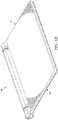
- FIG. 1A is a simplified schematic diagram illustrating an example of an electronic device 10 in an open configuration in accordance with one example of the present disclosure.
- Electronic device 10 may include a base portion 16, comprising a keyboard 12, a touchpad 18, and a top portion 14, comprising a display 26 and one or more discs 15.
- Display 26 may be disposed within/on and/or supported by top portion 14.
- display 26 is a screen that can be a liquid crystal display (LCD) display screen, a light-emitting diode (LED) display screen, an organic light-emitting diode (OLED) display screen, a plasma display screen, or any other suitable display screen system.
- LCD liquid crystal display
- LED light-emitting diode
- OLED organic light-emitting diode
- electronic device 10 is a notebook computer or laptop computer.
- electronic device 10 may be any suitable electronic device having a display such as a mobile device, a tablet computer and/or a tablet device (e.g., an i-PadTM), a personal digital assistant (PDA), a smartphone (an i-PhoneTM, AndroidTM, etc.), an audio system, a movie player of any type, a computer docking station, etc.
- a display such as a mobile device, a tablet computer and/or a tablet device (e.g., an i-PadTM), a personal digital assistant (PDA), a smartphone (an i-PhoneTM, AndroidTM, etc.), an audio system, a movie player of any type, a computer docking station, etc.
- PDA personal digital assistant
- smartphone an i-PhoneTM, AndroidTM, etc.
- an audio system e.g., a movie player of any type, a computer docking station, etc.
- electronic device 10 can offer a suitably comfortable grip for an end user to manipulate base portion 16 (e.g., to separate it from top portion 14).
- Electronic device 10 may also include one or multiple discs 15 that enable an integrated detachable accessory solution from mechanical, electrical, and aesthetical standpoints.
- the accessory band design feature can provide mechanical and magnetic lead-in guidance and attraction force for retention during docking.
- electronic device 10 may use a mechanical snap-in feature to easily attach, retain, and detach any accessory.
- the power of electronic device 10 can be physically isolated from its chassis and/or, further, it can be integrated within one or more of its disc assemblies.
- electronic device 10 can offer docking that allows power and/or data to flow between the device and the accessory (e.g., keyboard) to which it is docked.
- electronic device 10 can offer a space saving integration of a clutch mechanism residing inside the volume of the disc feature.
- electronic device 10 can offer an improved range of motion for the display when the device is oriented in a laptop mode, as detailed below.
- Electronic device 10 may also include a middle portion that is provided between base portion 16 and top portion 14.
- the middle portion may aesthetically cover a portion of hinges 15 (or be proximate to multiple hinges 15) existing between base portion 16 and top portion 14.
- Hinges 15 can define an axis of rotation that is shared between base portion 16 and top portion 14.
- base portion 16 and top portion 14 are hingedly coupled via one or more hinges 15 (as shown).
- electronic device 10 is a relatively thin and sleek tablet having a touch screen (e.g., 10-inch screen) and a detachable and re-attachable keyboard accessory.
- Electronic device 10 provides for an integrated device that can include a display section (containing a main logic board and barrel installed batteries) and a keyboard section.
- its hinge mechanism allows the display section to be attached to the keyboard in two different orientations: the display facing inward and the display facing outward.
- This mechanism can provide multiple modes (possible configurations), such as a laptop mode, tablet mode, movie mode (as well as closed mode) to a user. All of these configurations are discussed below with reference to various FIGURES that further illustrate some of the operational capabilities associated with electronic device 10.
- the keyboards that are currently available for tablets do not offer a suitable user experience. Typing on glass is ergonomically uncomfortable and, separately, typical Bluetooth keyboards are thick and cumbersome.
- the keyboard option for electronic device 10 can provide a user experience that replicates a more traditional computer keyboard experience.
- the key travel feels like a common computer keyboard (e.g., travel could be approximately 0.5 mm vs. 2.5 mm on a traditional computer keyboard, but feels the same).
- there is enough separation between the keys to make it easier for touch-typers to distinguish between keys for improved touch-typing.
- the keyboard is an ultra-thin (e.g., 3.30 mm), ultra-light (e.g., 275 grams) keyboard with sufficient keyboard band stiffness and strength to serve as a tablet device cover.
- the keyboard can be made from a laminate construction that uses variations of key design shapes and magnets to replicate a touch-typing user experience with the feel of a typical computer keyboard.
- the keyboard edge keys may be pivoted on one side and, further, may have magnets only on one side in a particular example of the present disclosure.
- the keys can be of any suitable type such as toggle operation keys, for example, with an arrow key operation that merges four keys that cannot move diagonally.
- a magnet can be provisioned at various locations of the keyboard (e.g., away from the center of the keys).
- Edge keys can be specially designed for thinner sides and, further, utilize varying magnet configurations.
- An edge key configuration allows keys to hang over the edge of the support base to accommodate the thinner sides of the keyboard device. Magnets can be suitably positioned to minimize the toggle affect.
- Toggle key configuration is used with the arrow keys.
- the use of magnets embedded within the keys and attracted to a ferrous top plate above the sides of the keys can provide the user with the sense of a traditional computer keyboard key travel and rigidity.
- the keyboard can also provide a physical keystroke confirming the depression of the key.
- the keyboard keys are magnetically biased upward with electrically conductive pads beneath the keys, which trigger a key press.
- a laminate construction may be employed in conjunction with an injection mold, where the metal is integrated into the plastic.
- a flexible printed circuit board (FPC) can also be used in certain examples of the present disclosure. Connections can be formed to the bands and a small battery may be optionally inserted into the keyboard to provide a limited backup power supply.
- the tablet keyboard dimensions are approximately: 261.40 mm(X) ⁇ 170.16 mm(Y)x3.30 mm (Z, key top-to-bottom surface).
- Other examples of the keyboard can include any suitable dimensions, sizes, and shapes: all of which are encompassed by the present disclosure.
- any number of connectors e.g., Universal Serial Bus (USB) connectors (e.g., in compliance with the USB 3.0 Specification, or any other version), ThunderboltTM connectors, WiFi connectors, a non-standard connection point such as a docking connector, etc.) and a plurality of antennas can be provisioned in conjunction with electronic device 10.
- USB Universal Serial Bus
- ThunderboltTM and the Thunderbolt logo are trademarks of Intel Corporation in the U.S. and/or other countries.
- the antennas are reflective of electrical components that can convert electric currents into radio waves.
- the antennas can be associated with WiFi activities, wireless connections more generally, small cell deployments, Bluetooth, 802.11, etc.
- the board (e.g., a motherboard) of electronic device 10 is a general circuit board that can hold various components of the internal electronic system of electronic device 10.
- the components may include a central processing unit (CPU), a memory, etc.
- the board can also couple to one or more connectors in order to accommodate other peripherals sought to be used by a user of electronic device 10. More specifically, the board can provide the electrical connections by which the other components of the system can communicate.
- processors inclusive of digital signal processors, microprocessors, supporting chipsets, etc.
- memory elements etc.
- Other components such as external storage, controllers for video display, sound, and peripheral devices may be attached to the board as plug-in cards, via cables, or integrated into the board itself.
- SOC system on chip
- CPU central processing unit
- An SOC represents an integrated circuit (IC) that integrates components of a computer or other electronic system into a single chip. It may contain digital, analog, mixed-signal, and often radio frequency functions: all of which may be provided on a single chip substrate.
- touchpad 18 is a pointing device that features a tactile sensor, a specialized surface that can translate the motion and position of a user's fingers to a relative position on screen.
- Touchpad 18 can be used in place of a mouse (e.g., where desk space is scarce or based on user preference).
- Touchpad 18 can operate using capacitive sensing, conductance sensing, or any other appropriate sensing technology.
- a suitable battery can be provisioned proximate to touchpad 18 in order to power its operations.
- either surface (or both surfaces) of display 26 can be a touch display that uses any of the technologies discussed herein.
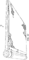
- FIG. 1B is a simplified schematic diagram illustrating a side view of electronic device 10 in a closed configuration.
- the thin plastic keyboard can protect the display.
- the display section When the display section is flipped up to an open position, it operates in a traditional laptop orientation (i.e., a keyboard resting on a surface with a display held in an upright position).
- electronic device 10 includes an 18.5 mm pitch full-size keyboard that provides for an optimal touch-typing experience.
- the display section is flipped upside-down to face outwardly away from the key elements of the keyboard, electronic device 10 can operate in a tablet configuration with the keyboard nested behind the screen and out of the way of user interaction.
- Its barrel-shaped hinge mechanism feature can serve as an ideal grip for the end user.
- the keyboard can be stowed behind the display.
- the display In the tablet mode, the display can still be flipped up.
- the keyboard In this mode, the keyboard can operate as a stand (behind the display), and the device can become a stationary display (e.g., movie mode).
- the display section When the display section is detached from the keyboard, it can function as a simple lightweight tablet by itself.
- the keyboard main components can include various elements.
- the keyboard can include a keyboard body reflective of a unibody-molded part that may use insert and/or comolding methods to eliminate visible fasteners.
- the keyboard body may further include insert-molded band features to provide stiffness to the outer portion of the scoop geometry as well as transmit rotational loads, which inhibit top portion 14 from rotating with respect to bottom portion 16.
- one or more band features that can provide for a magnetic attraction of the ferrous disc shaped features of the tablet. Electrical current can be passed from the tablet to the keyboard to recharge an on-board battery or capacitor, or power any number of items (e.g., a Bluetooth radio).
- the tablet can be suitably anchored to the keyboard to prohibit a toothed disc feature from rotating with respect to the keyboard, while allowing the tablet to concentrically rotate in the "scoop" part of the keyboard through one or more clutch elements in the tablet.
- the keys are configured with a 0.5 mm travel distance (for individual keys).
- tactile feedback can be provided (e.g., 70 gram with "cliff drop” force deflection feel) to mimic the typing experience of traditional keyboards.
- the keyboard can include pivoting keys (e.g., left edge: tilde, tab, caps lock, shift, left ctrl; right edge: backspace, backslash, enter, shift), rocking keys such as the arrow keys, and substantially vertical travel keys such as function keys and other keys that are not along the right or left edge, etc.
- Electronic device 10 can also include a nonferrous web that provides sufficient stiffness to the keyboard body.
- the web can provide a guide for keys to move vertically, but appropriately restrain x-y motion.
- a ferrous top plate can increase the stiffness of keyboard, retain keys from falling out, and attract magnetic keys to bias them upwards.
- the power can reach the radio by passing current through the bands/socket.
- the tablet can include electrically protected (but "hot") toothed discs.
- the Bluetooth radio circuit board can have a direct current (DC) rectifier to power the electronics independent of the orientation of the tablet (i.e., laptop mode vs. tablet mode, etc.).
- the design of electronic device 10 can allow a tablet to connect to the keyboard in both a laptop type mode and a tablet type mode, in addition to a movie stand type mode.
- the range of viewing angle adjustment is continuous (e.g., extending between 0 and 125°, or 150°, or more, or different ranges may be provided). 0° can correspond to the fully closed position, whereas 125° or similar can be defined as fully opened.
- FIG. 1C is a simplified schematic diagram illustrating an example of electronic device 10 in a closed configuration with an attached accessory cover in accordance with one example of the present disclosure.
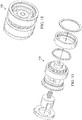
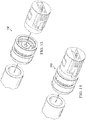
- FIGS. 1D-1E are simplified schematic diagrams illustrating an example of a USB connector assembly, which is generally indicated by an arrow 25.
- a particular example includes a USB connector 23, a SIM card 29, and a flexible printed circuit (FPC) 31.
- FPC flexible printed circuit
- a pre-load clamping post 27 is also provided to USB connector assembly 25.
- SIM card 29 is mounted in the USB assembly. The SIM card can be easily serviceable, yet hidden through the housing of the electronic device. As with the case of a mobile phone, the user can access the SIM card, but it is encased and protected in an appropriate manner.
- SIM card 29 represents an integrated circuit, which can securely store an identifier (e.g., international mobile subscriber identity (IMSI)) and/or the related key used to associate any user with a device.
- IMSI international mobile subscriber identity
- the SIM can identify and authenticate subscribers on computing devices (e.g., tablets, laptops, UltrabooksTM, mobile phones, smartphones, etc.).
- SIM card 29 can be transferred between different mobile devices.
- SIM card 29 may contain its unique serial number (ICCID), security authentication and ciphering information, temporary information related to the local network, a list of the services the user has access to, passwords, etc.
- ICCID unique serial number
- USB connector assembly 25 may include a SIM card clamping mechanism, which can offer a lower profile for the accompanying hardware.
- the clamping mechanism can use the barrel of the electronic device and a compression member (e.g., a pre-load of clamping post 27), which pushes against the outboard barrel (when assembled) to ensure an electrical connection between the SIM card and the SIM card cradle contacts.
- pre-load clamping post 27 (which could be a simple button, a dimple, a knob, any bias or spring-loaded component, etc.) can bias the center of the SIM card, as the SIM card-clamping mechanism is inserted into the housing of a given device.
- the button pushes against the inner wall of the barrel, which transfers a force to the SIM card that is subsequently pushed into the cradle.
- SIM card 29 is to be pressed against the contacts for the SIM card to be operational.
- the SIM card clamping mechanism represents a way to effectively position the SIM card into its cradle to ensure the appropriate contact.
- Pre-load clamping post 27 can also be part of a disassembly latch mechanism. This provides a mechanism for servicing/accessing the SIM card.
- SIM card 29 is provided with a hidden (but accessible) latching mechanism, along with an FPC with a service loop, which allows for the removal of the integrated USB/SIM assembly.
- USB connector assembly 25 also termed a USB module, as discussed herein
- the module can contain USB connector 23, the PCB, the clamping mechanism for the SIM card, and an interposer 35.
- a rigid flex cable assembly connects the module to a tablet board.
- the geometry of the flex and the way it is folded is such that it forms a single loop that is contained by a pocket within the module.
- the loop allows for the flex to be unfolded when the module is partially removed from the outboard barrel for SIM card servicing.
- interposer 35 is a vertically conductive material (e.g., having a 0.8 mm thickness). It can provide the electrical connection between the module's PCB and the SIM card.
- a SIM card can be positioned within a special keyed pocket and then pressed against interposer 35 by the clamping mechanism. The clamping can be actuated by inserting the module into the barrel.
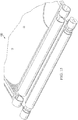
- FIGS. 1F-1G are simplified schematic diagrams illustrating one example insertion of USB connector assembly 25 into a housing of computing device (e.g., a tablet, a laptop, a mobile device of any kind, etc.).
- FIG. 1G illustrates USB connector assembly 25 having been removed.
- FIG. 1G also illustrates a self-contained latching assembly 39 and a related latching mechanism 33, which may or may not be spring-loaded.
- a small hole may be provided on top of latching mechanism 33 to house a spring that helps to bias the latch downward.
- Latching mechanism 33 can be manipulated (e.g., lifted by a tool, a paperclip, etc.) in order to release the USB assembly.
- the USB assembly can slide in an outboard direction (toward the right, in this illustration of FIG. 1G ).
- Collect mechanism 37 provides a selectively engageable clamping mechanism to retain one or more outboard ferrous rings 41.
- Ferrous rings 41 can include a plurality of balls (that are pushed radially outward), a rotatable locking cam ring that secures balls in the outward position when assembled, and a clocking feature that aligns with the USB/SIM assembly to prevent rotation of the locking cam ring when assembled. It should be noted that it is possible to eliminate this element by removing the collet and replacing it with snap rings to retain the outboard ferrous ring.
- USB connector assembly 25 can be secured within the barrel by latching mechanism 33.
- the access to the latching mechanism can be located out of sight, behind the toothed wheel/ferrous bands assembly.
- an operator can reach into the area behind the toothed wheel assembly and then press the latch with a small flat screwdriver (or a similar tool).
- the same outboard barrel that contains the USB module can also contain the toothed wheel/ferrous band support assembly.
- the assembly can be secured by a collet-type design that is actuated by a 60-degree turn of a pressure bushing.
- a bushing can be turned by a simple tool such as flat screwdriver, for example. Once rotated into position where it locks the assembly, the bushing is timed by USB module extension, which interlocks with a timing cut on the bushing, as the USB module is inserted.
- the pressure bushing is allowed to be rotated into the position where it releases the clutch assembly. Once the clutch assembly is released, it can be removed, part by part, and the battery can be serviced.
- FIG. 1H is a simplified schematic diagram illustrating an audio jack 45 in accordance with one example of the present disclosure.
- Audio jack 45 can receive any suitable audio, media, etc. input.
- audio jack 45 may include a spring-loaded contact 43 in a particular example.
- the audio jack connector is located in the outboard barrel, opposite of that containing the USB connector assembly. Its configuration can be similar to that of the USB module (in terms of assembly and electrical connectors to the board). It is not however intended to be removable by the user. In operation of one example scenario, after the audio jack module is installed, it also serves as a pillow block for the toothed wheel's outboard end of the shaft.
- the audio jack is mounted concentrically with the barrel, where the audio jack assembly slides into the barrel of the opposite end of the USB assembly.
- the audio jack can be held in place by a specialized retention mechanism (e.g., a nut that receives objects (e.g., screws, fasteners, etc.) from the inside portion of the barrel).
- the audio jack assembly can also provide a path of electrical conductivity between the toothed disc and the enclosure.
- Spring-loaded contact 43 is provided in the assembly and, further, can be loaded against the shaft of the clutch mechanism.
- the toothed disc is electrically conductive, while being isolated from the chassis. In one particular example, an electrical pathway is defined from the toothed disc, through the shaft of the clutch, and through spring-loaded contact 43, which can be viewed as a post that provides a suitable connection to the PCB of the audio jack assembly.
- a snap ring is used as a securing mechanism.
- the snap ring can be received or captured by the audio jack and, further, mate with an inner feature of a ferrous ring.
- the snap ring could mate to a feature in the inner wall of the circular recess (barrel) to provide support for the ferrous ring and to prevent the audio jack from falling out, but this method does not provide audio jack serviceability in the way other embodiments do, as discussed herein.
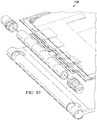
- FIG. 2 is a simplified schematic diagram illustrating an orthographic view of electronic device 10 being separated into two segments.
- FIG. 3 is a simplified schematic diagram illustrating an orthographic view of the electronic device when the two segments are connected together.
- the specific design of electronic device 10 integrates the clutch element the resides inside the volume of the disc features of the electronic device and, further, saves space by incorporating elements of the disc into the clutch (i.e., a toothed wheel).
- the design and assembly mechanism allows the tablet disc sub-assembly to be installed into a slot in the tablet enclosure that is smaller in width than the disc sub-assembly in its installed configuration.
- the actual disc can be designed with an electrical power connection that is physically isolated from the chassis.
- electronic device 10 offers a friction clutch integration with a disc-toothed wheel feature in the center (or other location) of the disc features in the electronic device (e.g., for improved range of motion, more compact size, position hold capabilities, and better torque transition characteristics).
- the magnetic band segments in the accessory can attract the ferrous rings of the tablet discs.
- the center rib (discussed in detail below) provides an amplified magnetic strength focused into the band.
- the center toothed wheel features of the tablet disc, which are connected to the clutch engage the tooth at the center of the accessory scope.
- the center rib of the accessory scoop can serve to provide a suitable alignment lead-in function.
- the encasing can provide a directional focus for the magnetic field.
- a clutch with bidirectional uniform torque properties is provisioned in the disc. This can allow top portion 14 to be inserted into bottom portion 16 in either orientation and, further, provide the uniform resistance to motion. This is in contrast to a typical standard laptop clutch, which may provide less resistance in one direction or variable resistance based on the angle between the screen and the keyboard.
- FIG. 4 is a simplified orthographic view of a disc groove 40 of electronic device 10.
- disc groove 40 can be in the range of 1.0-3.5 millimeters, although alternative examples could have any other suitable dimension.
- FIG. 5 is a simplified schematic diagram illustrating an orthographic view of a potential accessory of electronic device 10 in accordance with one example implementation. This particular example includes symmetrical segments 50a-50b that can engender a suitable coupling for a given accessory.
- an accessory such as a keyboard, when attached, becomes integrated to allow power to flow between the tablet's disc mechanism and the keyboard and, thus, power the Bluetooth radio embedded in the keyboard.
- FIG. 6 is a simplified schematic diagram illustrating an orthographic view of an accessory dock 60 of electronic device 10 in accordance with one example of the present disclosure.
- Accessory dock 60 can provide a suitable lead-in/guidance feature during connection activities.
- FIG. 7 is a simplified schematic diagram illustrating the underside of the accessory band components associated with electronic device 10.
- Magnet components 70 on the opposite side (and installed in the band) may be accompanied by a suitable backing (e.g., a steel backing) to reduce unwanted stray magnetic fields. Without such a backing, magnetic forces would have an increased likelihood of interaction with other components, alter credit card information, corrupt certain storage elements, etc.
- a suitable backing e.g., a steel backing
- the shape of the band/keyboard and the tablet transition can allow for a cam-out release of the tablet from the keyboard by using the tablet as a lever to overcome the strong magnetic pull force of the connection.
- the magnetic pull from the keyboard to the tablet can ensure an electric contact and mechanical connection between the keyboard bands and the tablet.
- the clutch assembly can be electrically isolated from the tablet and keyboard enclosures to allow positive and negative connections between the tablet and the keyboard made through the two clutches.
- the physical contact of the toothed wheel features of the tablet disc elements to the torque transmission tooth of the keyboard bands allows for electrical power and/or signals to pass from the tablet to the keyboard.
- the toothed disc can suitably transmit torque from the keyboard to the tablet. Additionally, certain examples may use a plastic-housed clutch element to electrically isolate the toothed disc from the chassis.
- FIG. 8 is a simplified schematic diagram illustrating an orthographic view of the keyboard electronics and magnetic bands 80 with the surrounding keyboard housing removed.
- FIG. 9 illustrates a keyboard housing 90 with the associated keyboard electronics and magnetic bands removed.
- FIG. 10 is a simplified schematic diagram illustrating a hinge assembly 100 associated with electronic device 10.
- FIGS. 11-14 are simplified schematic diagrams illustrating certain hinge assembly components 110/120/130/140 associated with electronic device 10. The design and assembly mechanism of electronic device 10 allows assembly of the tablet disc into a slot that is smaller than the assembled disc.
- FIG. 15 is a simplified schematic diagram illustrating one potential design arrangement 150 associated with the present disclosure.
- a three-piece snap for purposes of retention.
- Power signals can propagate through each of the three pieces separately.
- the power signals can run through the middle piece, where the two outer pieces operate as insulators.
- a keyboard side snap can be provided with one piece, where slots are used to allow for an independent motion of the outer snap bands and inner torque grabbing band/tooth.
- a one-piece snap can be provided without a separation of the three sections.
- any suitable plastic, fiber-reinforced plastic, highly elastic metal (e.g., titanium) can be used in such examples.
- the one-piece snap, three-piece snap, and the magnetic retention can all be implemented without a clutch in the electronic device. For example, instead of using a clutch mechanism, the electronic device and the accessory can be held in position angularly with respect to one another (e.g., with the friction of their respective cylindrical mating surfaces).
- the clutch mechanism does not have to be internal to the device discs (e.g., they can be in the area shown as being occupied by batteries in certain FIGURES). In essence, any clutch mechanism can be used in order to accommodate the teachings of the present disclosure. Additionally, friction forces do not have to be equal in both directions in certain examples of the present disclosure.
- one of the two ferrous steel bands can be assembled with the torque insert and then inserted into the tablet by sliding it into the center barrel section with the second ferrous steel band loosely present over the center-toothed disc, which has a smaller outer diameter than the inner diameter of the ferrous steel band. Subsequently, the connector sub-assembly can be pushed in from the outside through the outer portion of the tablet barrel and the second ferrous steel band can be secured onto it.
- certain configurations can pass power signals through one or a plurality of discs with wiping contacts on the accessory side.
- Other configurations can pass power signals through disc features that are not necessarily the ferrous features being shown, but any other ring of metal could be used as a contact.
- power signals can be passed through a plug-in connector (e.g., whose male side protrusion is built into the keyboard side and whose female side is built into the electronic device). This could effectively make the electrical connection and, further, could be used as the sole point of torque transmission between the keyboard and the tablet. Note that such an example is like a scaled-up version of the tooth engaging in the toothed wheel.
- FIG. 16 is a simplified schematic diagram illustrating an alternative docking station 160 example associated with electronic device 10.
- the disc hinge design of the present disclosure (with power isolated from the chassis) enables a more fully integrated tablet accessory capability, thus engendering countless functioning tablet accessories.
- docking station 160 is one such implementation.
- FIG. 17 is a simplified schematic diagram illustrating an alternative speaker example 170 associated with electronic device 10. Any suitable audio system can be provisioned in conjunction with the present disclosure, as the depiction of FIG. 17 is only being offered by way of example.
- FIG. 18 is a simplified schematic diagram illustrating an alternative hinge design 180 that uses a discrete ball detent mechanism.
- a detent is a device used to mechanically resist or arrest the rotation of a wheel, axle, or spindle. Such a device can be anything ranging from a simple metal pin to a machine. In a particular example, the detent is used to simply arrest rotation in one direction, or to intentionally divide a rotation into discrete increments.
- FIG. 19 is a simplified block diagram illustrating potential electronics associated with electronic device 10. More particularly, FIG. 19 illustrates an example of an example system 2600 that may be included in any portion (or shared by portions) of electronic device 10.
- System 2600 includes a touch input device 2502, a touch controller 2602, one or more processors 2604, system control logic 2606 coupled to at least one of processor(s) 2604, system memory 2608 coupled to system control logic 2606, non-volatile memory and/or storage device(s) 2610 coupled to system control logic 2606, display controller 2612 coupled to system control logic 2606, display controller 2612 coupled to a display, power management controller 2618 coupled to system control logic 2606, and communication interfaces 2620 coupled to system control logic 2606.
- Touch input device 2502 includes touch sensor 2520 and each may be implemented using any suitable touch-sensitive technology such as, for example and without limitation, capacitive, resistive, surface acoustic wave (SAW), infrared, and optical imaging. Touch input device 2502, in a particular example, may be implemented using any suitable multi-touch technology.
- touch-sensitive technology such as, for example and without limitation, capacitive, resistive, surface acoustic wave (SAW), infrared, and optical imaging.
- SAW surface acoustic wave
- Touch input device 2502 in a particular example, may be implemented using any suitable multi-touch technology.
- System control logic 2606 may include any suitable interface controllers to provide for any suitable interface to at least one processor 2604 and/or to any suitable device or component in communication with system control logic 2606.
- System control logic 2606 in a particular example, may include one or more memory controllers to provide an interface to system memory 2608.
- System memory 2608 may be used to load and store data and/or instructions, for example, for system 2600.
- System memory 2608 in a particular example, may include any suitable volatile memory, such as suitable dynamic random access memory (DRAM) for example.
- System control logic 2606 in a particular example, may include one or more input/output (I/O) controllers to provide an interface to a display device, touch controller 2602, and non-volatile memory and/or storage device(s) 2610.
- I/O input/output
- Non-volatile memory and/or storage device(s) 2610 may be used to store data and/or instructions, for example within software 2628.
- Non-volatile memory and/or storage device(s) 2610 may include any suitable non-volatile memory, such as flash memory for example, and/or may include any suitable non-volatile storage device(s), such as one or more hard disc drives (HDDs), one or more compact disc (CD) drives, and/or one or more digital versatile disc (DVD) drives for example.
- HDDs hard disc drives
- CD compact disc
- DVD digital versatile disc
- Power management controller 2618 includes power management logic 2630 configured to control various power management and/or power saving functions of electronic device 10 based upon whether electronic device 10 is in an open configuration or a closed configuration and/or a physical orientation of electronic device 10. In one example, power management controller 2618 is configured to reduce the power consumption of components or devices of system 2600 that may either be operated at reduced power or turned off when electronic device 10 is in the closed configuration.
- power management controller 2618 may perform one or more of the following: power down the unused portion of the display and/or any backlight associated therewith; allow one or more of processor(s) 2604 to go to a lower power state if less computing power is required in the closed configuration; and shutdown any devices and/or components, such as keyboard 108, that are unused when electronic device 10 is in the closed configuration.
- Communications interface(s) 2620 may provide an interface for system 2600 to communicate over one or more networks and/or with any other suitable device. Communications interface(s) 2620 may include any suitable hardware and/or firmware. Communications interface(s) 2620, in a particular example, may include, for example, a network adapter, a wireless network adapter, a telephone modem, and/or a wireless modem.
- System control logic 2606 may include one or more input/output (I/O) controllers to provide an interface to any suitable input/output device(s) such as, for example, an audio device to help convert sound into corresponding digital signals and/or to help convert digital signals into corresponding sound, a camera, a camcorder, a printer, and/or a scanner.
- I/O input/output
- At least one processor 2604 may be packaged together with logic for one or more controllers of system control logic 2606. In one example, at least one processor 2604 may be packaged together with logic for one or more controllers of system control logic 2606 to form a System in Package (SiP). In one example, at least one processor 2604 may be integrated on the same die with logic for one or more controllers of system control logic 2606. For a particular example, at least one processor 2604 may be integrated on the same die with logic for one or more controllers of system control logic 2606 to form a System on Chip (SoC).
- SoC System on Chip
- touch controller 2602 may include touch sensor interface circuitry 2622 and touch control logic 2624.
- Touch sensor interface circuitry 2622 may be coupled to detect touch input over a first touch surface layer and a second touch surface layer of display 26 (i.e., display device 2510).
- Touch sensor interface circuitry 2622 may include any suitable circuitry that may depend, for example, at least in part on the touch-sensitive technology used for touch input device 2502.
- Touch sensor interface circuitry 2622 in one example, may support any suitable multi-touch technology.
- Touch sensor interface circuitry 2622 in one example, may include any suitable circuitry to convert analog signals corresponding to a first touch surface layer and a second surface layer into any suitable digital touch input data. Suitable digital touch input data for one example may include, for example, touch location or coordinate data.
- Touch control logic 2624 may be coupled to help control touch sensor interface circuitry 2622 in any suitable manner to detect touch input over a first touch surface layer and a second touch surface layer. Touch control logic 2624 for one example may also be coupled to output in any suitable manner digital touch input data corresponding to touch input detected by touch sensor interface circuitry 2622. Touch control logic 2624 may be implemented using any suitable logic, including any suitable hardware, firmware, and/or software logic (e.g., non-transitory tangible media), that may depend, for example, at least in part on the circuitry used for touch sensor interface circuitry 2622. Touch control logic 2624 for one example may support any suitable multi-touch technology.
- Touch control logic 2624 may be coupled to output digital touch input data to system control logic 2606 and/or at least one processor 2604 for processing. At least one processor 2604 for one example may execute any suitable software to process digital touch input data output from touch control logic 2624. Suitable software may include, for example, any suitable driver software and/or any suitable application software. As illustrated in FIG. 19 , system memory 2608 may store suitable software 2626 and/or non-volatile memory and/or storage device(s).
- Example A can include an electronic device, such as a notebook computer or laptop, which includes a circuit board coupled to a plurality of electronic components (which includes any type of hardware, elements, circuitry, etc.).
- the electronic device may also include a connector assembly that is to be positioned within at least a portion of a recess of the electronic device, where the connector assembly includes: a first assembly (e.g., a universal serial bus (USB) assembly) that is to receive a connector (e.g., a USB component such as a USB cable, wire, male or female connector, thumb-drive, flash drive, etc.); and a second assembly (e.g., a subscriber identification module (SIM) assembly) that is to receive an identification module (e.g., a SIM card) that is to provide an association between a user and the electronic device.
- a first assembly e.g., a universal serial bus (USB) assembly
- a connector e.g., a USB component such as a USB cable, wire, male
- Example B the subject matter of Example A can optionally include an audio jack assembly that is to receive an audio input, where the audio jack assembly is provided concentrically with a circular recess of the electronic device.
- the audio jack assembly is secured by a retention mechanism that is to receive an object from an internal portion of the circular recess.
- the audio jack assembly can further include a spring-loaded contact that is to be loaded against a shaft of a clutch mechanism of the electronic device. An electrical pathway can be defined from the shaft of the clutch through the spring-loaded contact.
- the spring-loaded contact can be a post that provides a connection to a circuit board of the audio jack assembly.
- an electronic device may include means for receiving a connector assembly (e.g., through any suitable hardware, housing, etc.) that is to be positioned within a recess of an electronic device, where the connector assembly may include a USB assembly that is to receive a USB component; and a SIM assembly that is to receive a SIM card that is to provide an association between a user and the electronic device.
- the electronic device may also include means for facilitating an electrical contact between the electronic device and the connector assembly (e.g., using any suitable interface, link, bus, communication pathway, hardware, processor, software, circuitry, a hub, a controller, etc.).
- An electronic device comprising:
- the connector assembly further comprises:
- the connector assembly further comprises:
- the connector assembly further comprises:
- collet mechanism further includes one or more balls that are to push against an inner surface of the recess.
- collet mechanism further includes a rotatable locking cam ring to secure the one or more balls in an outward position.
- An electronic device comprising:
- the audio jack assembly further comprises:
- a method comprising:
- the second assembly is a subscriber identification module (SIM) assembly, and wherein the identification module is a SIM card.
- SIM subscriber identification module
- An apparatus comprising:
- USB universal serial bus
- the second assembly is a subscriber identification module (SIM) assembly, and wherein the identification module is a SIM card.
- SIM subscriber identification module
Landscapes
- Engineering & Computer Science (AREA)
- Theoretical Computer Science (AREA)
- Computer Hardware Design (AREA)
- Physics & Mathematics (AREA)
- General Engineering & Computer Science (AREA)
- General Physics & Mathematics (AREA)
- Human Computer Interaction (AREA)
- Computer Security & Cryptography (AREA)
- Computer Networks & Wireless Communication (AREA)
- Mathematical Physics (AREA)
- Power Engineering (AREA)
- Software Systems (AREA)
- Signal Processing (AREA)
- Manufacturing & Machinery (AREA)
- Mechanical Engineering (AREA)
- Casings For Electric Apparatus (AREA)
- Details Of Connecting Devices For Male And Female Coupling (AREA)
- Coupling Device And Connection With Printed Circuit (AREA)
- Telephone Set Structure (AREA)
- Mounting Components In General For Electric Apparatus (AREA)
- Input From Keyboards Or The Like (AREA)
Applications Claiming Priority (2)
| Application Number | Priority Date | Filing Date | Title |
|---|---|---|---|
| US13/839,448 US9176537B2 (en) | 2013-03-15 | 2013-03-15 | Connector assembly for an electronic device |
| EP14765000.6A EP2972649B1 (en) | 2013-03-15 | 2014-03-14 | Connector assembly for an electronic device |
Related Parent Applications (2)
| Application Number | Title | Priority Date | Filing Date |
|---|---|---|---|
| EP14765000.6A Division EP2972649B1 (en) | 2013-03-15 | 2014-03-14 | Connector assembly for an electronic device |
| EP14765000.6A Division-Into EP2972649B1 (en) | 2013-03-15 | 2014-03-14 | Connector assembly for an electronic device |
Publications (1)
| Publication Number | Publication Date |
|---|---|
| EP3246786A1 true EP3246786A1 (en) | 2017-11-22 |
Family
ID=51529068
Family Applications (6)
| Application Number | Title | Priority Date | Filing Date |
|---|---|---|---|
| EP17177711.3A Pending EP3246786A1 (en) | 2013-03-15 | 2014-03-14 | Connector assembly for an electronic device |
| EP17177712.1A Active EP3293601B1 (en) | 2013-03-15 | 2014-03-14 | Connector assembly for an electronic device |
| EP17177710.5A Pending EP3249495A1 (en) | 2013-03-15 | 2014-03-14 | Connector assembly for an electronic device |
| EP14765000.6A Active EP2972649B1 (en) | 2013-03-15 | 2014-03-14 | Connector assembly for an electronic device |
| EP17177709.7A Pending EP3246785A1 (en) | 2013-03-15 | 2014-03-14 | Connector assembly for an electronic device |
| EP17177713.9A Active EP3293602B1 (en) | 2013-03-15 | 2014-03-14 | Connector assembly for an electronic device |
Family Applications After (5)
| Application Number | Title | Priority Date | Filing Date |
|---|---|---|---|
| EP17177712.1A Active EP3293601B1 (en) | 2013-03-15 | 2014-03-14 | Connector assembly for an electronic device |
| EP17177710.5A Pending EP3249495A1 (en) | 2013-03-15 | 2014-03-14 | Connector assembly for an electronic device |
| EP14765000.6A Active EP2972649B1 (en) | 2013-03-15 | 2014-03-14 | Connector assembly for an electronic device |
| EP17177709.7A Pending EP3246785A1 (en) | 2013-03-15 | 2014-03-14 | Connector assembly for an electronic device |
| EP17177713.9A Active EP3293602B1 (en) | 2013-03-15 | 2014-03-14 | Connector assembly for an electronic device |
Country Status (10)
| Country | Link |
|---|---|
| US (10) | US9176537B2 (ja) |
| EP (6) | EP3246786A1 (ja) |
| JP (7) | JP6055119B2 (ja) |
| KR (7) | KR101703201B1 (ja) |
| CN (6) | CN107015605B (ja) |
| BR (6) | BR122017012058A2 (ja) |
| GB (6) | GB2562545B (ja) |
| RU (6) | RU2681337C2 (ja) |
| TW (1) | TWI550385B (ja) |
| WO (1) | WO2014144271A1 (ja) |
Families Citing this family (60)
| Publication number | Priority date | Publication date | Assignee | Title |
|---|---|---|---|---|
| DE202011107782U1 (de) * | 2011-11-11 | 2012-01-24 | Marcus Kuchler | Modulare lineare Halte- und Verbindungsvorrichtung für Apple Geräte mit "Dock - Anschluss" |
| TWI502320B (zh) * | 2013-02-27 | 2015-10-01 | Wistron Corp | 電子設備 |
| US9176537B2 (en) | 2013-03-15 | 2015-11-03 | Intel Corporation | Connector assembly for an electronic device |
| WO2015080695A1 (en) * | 2013-11-26 | 2015-06-04 | Hewlett-Packard Development Company, L.P. | Electronic device accessory with at least one port |
| US9478886B1 (en) * | 2014-06-10 | 2016-10-25 | Google Inc. | Jack with cylindrical housing |
| TWM489578U (en) * | 2014-07-17 | 2014-11-11 | Mywish Information Corp | Rotation structure of storage rack |
| CN105334944B (zh) * | 2014-08-12 | 2018-08-10 | 联想(北京)有限公司 | 电子设备及连接装置 |
| TWI511651B (zh) * | 2014-09-05 | 2015-12-01 | Acer Inc | 電子裝置 |
| US10088864B2 (en) * | 2014-09-26 | 2018-10-02 | Intel Corporation | Wireless gimbal connection for electronic devices |
| CN104375575B (zh) * | 2014-10-31 | 2018-04-27 | 合肥联宝信息技术有限公司 | 一种笔记本计算机的按压连接器 |
| US20160179140A1 (en) * | 2014-12-20 | 2016-06-23 | Intel Corporation | Chassis Design for Wireless-Charging Coil Integration for Computing Systems |
| US10003218B2 (en) * | 2014-12-20 | 2018-06-19 | Intel Corporation | Chassis design for wireless-charging coil integration for computing systems |
| US9794660B2 (en) * | 2015-09-25 | 2017-10-17 | Intel Corporation | Integrated sound bar hinge assembly for mobile electronic device |
| CN105448314B (zh) * | 2015-12-25 | 2018-05-25 | 陈�峰 | 一种大屏幕汽车导航娱乐系统 |
| CN105929897A (zh) * | 2016-04-18 | 2016-09-07 | 惠州Tcl移动通信有限公司 | 一种平板电脑套件及其支撑键盘 |
| USD820266S1 (en) * | 2016-04-18 | 2018-06-12 | Compal Electronics, Inc. | Connecting device |
| TWI595717B (zh) * | 2016-04-21 | 2017-08-11 | 華碩電腦股份有限公司 | 連接器結構 |
| CN107765767B (zh) * | 2016-08-23 | 2020-06-05 | 华硕电脑股份有限公司 | 电子装置 |
| US9995070B2 (en) * | 2016-08-30 | 2018-06-12 | Apple Inc. | Hinge release mechanism |
| US11188128B2 (en) * | 2016-10-17 | 2021-11-30 | Lenovo (Singapore) Pte. Ltd. | Convertible electronic apparatus |
| USD842679S1 (en) * | 2017-02-15 | 2019-03-12 | Southco, Inc. | Hinge |
| CN108626240A (zh) * | 2017-03-17 | 2018-10-09 | 富泰华工业(深圳)有限公司 | 旋转结构及具有该旋转结构的电子装置 |
| US9939852B1 (en) | 2017-05-08 | 2018-04-10 | Microsoft Technology Licensing, Llc | Hinge assembly |
| CN107035253A (zh) * | 2017-05-26 | 2017-08-11 | 五冶集团上海有限公司 | 一种可固定角度的铰链 |
| USD883284S1 (en) * | 2017-07-19 | 2020-05-05 | Lg Electronics Inc. | Portable wireless keyboard |
| CN109413230A (zh) * | 2017-08-17 | 2019-03-01 | 富泰华工业(深圳)有限公司 | 双屏电子装置 |
| CN107387542B (zh) * | 2017-09-21 | 2019-07-26 | 广东虹勤通讯技术有限公司 | 一种转轴型连接装置 |
| USD839714S1 (en) * | 2017-12-04 | 2019-02-05 | Compal Electronics, Inc. | Hinge |
| USD900090S1 (en) * | 2018-03-19 | 2020-10-27 | Beijing Xiaomi Mobile Software Co., Ltd. | Laptop computer |
| USD858251S1 (en) * | 2018-05-06 | 2019-09-03 | van Cronenburg Architectural Hardware BVBA | Offset pivot hinge |
| CN110515423B (zh) * | 2018-05-22 | 2023-05-23 | 仁宝电脑工业股份有限公司 | 电子装置 |
| USD858252S1 (en) * | 2018-05-25 | 2019-09-03 | Fiasco Limited | Flip over hinge |
| US10534407B2 (en) * | 2018-09-25 | 2020-01-14 | Intel Corporation | On-demand torque engagement mechanism for second display adjustability |
| TWI690118B (zh) | 2018-11-23 | 2020-04-01 | 元太科技工業股份有限公司 | 連接結構及具有連接結構的顯示面板裝置 |
| CN111313169B (zh) * | 2018-11-23 | 2022-03-01 | 元太科技工业股份有限公司 | 连接结构及具有连接结构的显示面板装置 |
| USD916576S1 (en) * | 2018-12-26 | 2021-04-20 | Hsing Hua Kuan | Hinge |
| CN110401081B (zh) * | 2019-03-28 | 2024-04-02 | 上海徕木电子股份有限公司 | 一种转轴连接器 |
| US11349249B2 (en) * | 2019-09-27 | 2022-05-31 | Apple Inc. | Circular connector in integrated in hinge |
| USD927488S1 (en) * | 2019-11-21 | 2021-08-10 | Kye Systems Corp. | Keyboard |
| US11561586B2 (en) * | 2020-03-09 | 2023-01-24 | Apple Inc. | Accessory devices for electronic devices |
| WO2021216051A1 (en) * | 2020-04-21 | 2021-10-28 | Hewlett-Packard Development Company, L.P. | Computing device enclosures with deployable covers |
| USD957398S1 (en) * | 2020-06-05 | 2022-07-12 | Asustek Computer Inc. | Portable docking station |
| US11216043B1 (en) * | 2020-07-31 | 2022-01-04 | Lenovo (Singapore) Pte. Ltd. | System hinge assembly |
| KR102290899B1 (ko) * | 2020-10-29 | 2021-08-19 | 삼성전자주식회사 | 플렉서블 디스플레이를 포함하는 전자 장치 |
| US20230409076A1 (en) * | 2020-10-29 | 2023-12-21 | Hewlett-Packard Development Company, L.P. | Accessory hangers |
| USD1016799S1 (en) * | 2020-11-17 | 2024-03-05 | Samsung Electronics Co., Ltd. | Monitor for laptop computer |
| USD1024050S1 (en) * | 2020-11-17 | 2024-04-23 | Samsung Electronics Co., Ltd. | Laptop computer |
| USD1018525S1 (en) * | 2020-11-17 | 2024-03-19 | Samsung Electronics Co., Ltd. | Laptop computer |
| USD1016801S1 (en) * | 2020-12-17 | 2024-03-05 | Samsung Electronics Co., Ltd. | Notebook computer |
| USD1016802S1 (en) * | 2020-12-17 | 2024-03-05 | Samsung Electronics Co., Ltd. | Notebook computer |
| USD1016800S1 (en) * | 2020-12-17 | 2024-03-05 | Samsung Electronics Co., Ltd. | Notebook computer |
| USD1025978S1 (en) * | 2020-12-28 | 2024-05-07 | Samsung Display Co., Ltd. | Notebook computer |
| USD1022986S1 (en) * | 2021-02-18 | 2024-04-16 | Huawei Technologies Co., Ltd. | Laptop |
| USD1018539S1 (en) * | 2021-02-18 | 2024-03-19 | Huawei Technologies Co., Ltd. | Keyboard |
| JP7011094B1 (ja) * | 2021-02-24 | 2022-01-26 | レノボ・シンガポール・プライベート・リミテッド | 電子機器 |
| USD989077S1 (en) * | 2021-05-07 | 2023-06-13 | Dongguan Kaishuo Electronic Technology Co., Ltd | Tablet keyboard case |
| JP1721017S (ja) * | 2021-06-01 | 2022-07-29 | 携帯用電子計算機接続端子付きキーボード | |
| TWI811743B (zh) * | 2021-07-22 | 2023-08-11 | 仁寶電腦工業股份有限公司 | 折疊式電子裝置 |
| US11644871B1 (en) * | 2022-02-11 | 2023-05-09 | Dell Products L.P. | Systems and methods for determining hinge angle position in an information handling system |
| TWI817723B (zh) * | 2022-09-16 | 2023-10-01 | 宏碁股份有限公司 | 折疊式電子裝置 |
Citations (3)
| Publication number | Priority date | Publication date | Assignee | Title |
|---|---|---|---|---|
| US20050050686A1 (en) * | 2003-06-30 | 2005-03-10 | Casio Computer Co., Ltd. | Two-shaft hinge structure |
| US20060288534A1 (en) * | 2005-06-24 | 2006-12-28 | Sheng-Fu Lu | Positioning structure for pivotal shaft |
| TWM439836U (en) * | 2012-06-04 | 2012-10-21 | Pegatron Corp | Docking station and portable apparatus |
Family Cites Families (176)
| Publication number | Priority date | Publication date | Assignee | Title |
|---|---|---|---|---|
| US625276A (en) * | 1899-05-16 | John sciiade | ||
| SU1034047A1 (ru) * | 1982-03-12 | 1983-08-07 | Куйбышевский инженерно-строительный институт им.А.И.Микояна | Механический интегратор |
| US4590337A (en) * | 1984-11-28 | 1986-05-20 | Engelmore Anthony R | Rotatable electrical connector for coiled telephone cords |
| US5118309A (en) * | 1991-04-01 | 1992-06-02 | Motorola, Inc. | Minimum wire interface for multiple accessories |
| US5796575A (en) * | 1992-12-21 | 1998-08-18 | Hewlett-Packard Company | Portable computer with hinged cover having a window |
| USD356072S (en) | 1993-09-09 | 1995-03-07 | Compaq Computer Corporation | Notebook personal computer |
| US5773332A (en) * | 1993-11-12 | 1998-06-30 | Xircom, Inc. | Adaptable communications connectors |
| US5970418A (en) | 1995-09-21 | 1999-10-19 | International Business Machines Corporation | Personal communicator including a handset phone with an integrated virtual image display |
| JP3495249B2 (ja) * | 1998-02-27 | 2004-02-09 | 京セラ株式会社 | 折り畳み型電子機器 |
| JP4212708B2 (ja) | 1998-03-16 | 2009-01-21 | 富士通株式会社 | 情報処理装置及び電子機器 |
| DE29805644U1 (de) | 1998-03-27 | 1998-06-18 | Lu Ching Shui | Drehbare Anschlußbuchse für ein Telefonkabel |
| US6362440B1 (en) * | 1998-03-27 | 2002-03-26 | International Business Machines Corporation | Flexibly interfaceable portable computing device |
| US5987704A (en) | 1998-04-15 | 1999-11-23 | Apple Computer, Inc. | Dual axis hinge apparatus with braking mechanism |
| AU137484S (en) | 1998-05-28 | 1999-06-11 | Nec Corp | A personal computer |
| US6252767B1 (en) * | 1999-06-22 | 2001-06-26 | Hewlett-Packard Company | Low impedance hinge for notebook computer |
| DE19940695B4 (de) * | 1999-08-27 | 2008-03-27 | ITT Manufacturing Enterprises, Inc., Wilmington | Elektronisches Mediagerät |
| JP2001237932A (ja) * | 2000-02-21 | 2001-08-31 | Nec Corp | 携帯端末装置および無線通信端末装置 |
| US20040049743A1 (en) * | 2000-03-31 | 2004-03-11 | Bogward Glenn Rolus | Universal digital mobile device |
| EP1174945B1 (en) * | 2000-07-18 | 2006-05-03 | Option | Telecommunications card with integrated antenna |
| US6781823B1 (en) * | 2000-11-13 | 2004-08-24 | Norris G Nyack, Jr. | Complete office portable computers improvement |
| US6368156B1 (en) * | 2000-12-27 | 2002-04-09 | Hon Hai Precision Ind. Co., Ltd. | Audio jack conveniently and reliably mounted on a circuit board |
| DE60119681T2 (de) * | 2000-12-28 | 2007-05-10 | Cellon France S.A.S. | Elektronische Vorrichtung mit zwei zueinander beweglichen Teilen |
| TW482355U (en) * | 2001-03-20 | 2002-04-01 | Hon Hai Prec Ind Co Ltd | Socket connector |
| US6583984B2 (en) * | 2001-03-23 | 2003-06-24 | Hewlett-Packard Development Company, L.P. | Multi-position computing device docking station |
| US6755694B2 (en) | 2001-04-19 | 2004-06-29 | Medtronic, Inc. | Lead upsizing sleeve |
| US6802717B2 (en) * | 2001-04-26 | 2004-10-12 | Felix Castro | Teaching method and device |
| US6679718B2 (en) * | 2001-07-18 | 2004-01-20 | Hewlett-Packard Development Company, L.P. | Collapsible RJ11/RJ45 connector for type II PC card extension cord application |
| KR100439719B1 (ko) | 2002-01-08 | 2004-07-12 | 삼성전자주식회사 | 노트북 컴퓨터 |
| US6964586B2 (en) * | 2002-02-08 | 2005-11-15 | Microsoft Corporation | Reduced size eight-pin audio jack electrical connector |
| JP3673766B2 (ja) * | 2002-04-03 | 2005-07-20 | Necアクセステクニカ株式会社 | ヒンジ |
| TW592025B (en) * | 2002-05-24 | 2004-06-11 | Molex Inc | Hinge connector for electronic devices |
| JP2004021451A (ja) * | 2002-06-14 | 2004-01-22 | Casio Comput Co Ltd | 電子機器 |
| JP2004118794A (ja) * | 2002-09-30 | 2004-04-15 | Brother Ind Ltd | 巻込可能なディスプレイと折畳可能なキーボードを備えた入力装置並びにその入力装置を備えたパーソナルコンピュータ |
| US6675694B1 (en) | 2003-01-07 | 2004-01-13 | The United States Of America As Represented By The Secretary Of The Navy | Machine gun and ammunition can interface gun mount |
| US6851975B2 (en) * | 2003-02-10 | 2005-02-08 | Sony Ericsson Mobile Communications Ab | Impact tolerant connector |
| US7241179B2 (en) * | 2003-03-05 | 2007-07-10 | Sony Ericsson Mobile Communications Ab | Universal audio jack and plug |
| CN2609231Y (zh) * | 2003-03-21 | 2004-03-31 | 莫列斯公司 | 音频插座连接器 |
| US7533408B1 (en) * | 2003-06-13 | 2009-05-12 | Michael Arnouse | Portable computing system, apparatus and method |
| KR100827104B1 (ko) | 2003-10-23 | 2008-05-02 | 삼성전자주식회사 | 휴대용 전자 장치 |
| JP4048435B2 (ja) | 2003-10-23 | 2008-02-20 | ソニー株式会社 | 電子機器 |
| JP2005165637A (ja) * | 2003-11-11 | 2005-06-23 | Sony Corp | 電子機器及びバッテリー |
| EP2242231A1 (en) * | 2003-11-12 | 2010-10-20 | Qualcomm Incorporated | High data rate interface with improved link control |
| US20070113440A1 (en) | 2003-11-13 | 2007-05-24 | Asvadi Farshid H | Electroluminescent sign |
| US20050122671A1 (en) * | 2003-12-09 | 2005-06-09 | Homer Steven S. | Electronic device with improved hinge |
| TWI230535B (en) * | 2004-02-20 | 2005-04-01 | Benq Corp | Rotary apparatus having digital camera module |
| KR100663573B1 (ko) * | 2004-06-21 | 2007-01-02 | 삼성전자주식회사 | 3축 회전 폴더 타입 휴대 장치 |
| US6971907B1 (en) * | 2004-07-13 | 2005-12-06 | Nvidia Corporation | Configurable lighted connector |
| US7189023B2 (en) | 2004-09-01 | 2007-03-13 | Micro-Star Int'l Co., Ltd. | Rotational positioning apparatus |
| JP2006091260A (ja) * | 2004-09-22 | 2006-04-06 | Fuji Photo Film Co Ltd | レンズ駆動装置及びデジタルカメラ |
| US7373446B2 (en) * | 2004-11-05 | 2008-05-13 | Microsoft Corporation | Method and system for dynamically patching an operating system's interrupt mechanism |
| USD540804S1 (en) | 2004-12-27 | 2007-04-17 | Brother Industries, Ltd. | Charging device with display monitor |
| US20090011793A1 (en) * | 2005-01-13 | 2009-01-08 | Pocrass Alan L | Flash Memory Cell Phone With Integrated Male And Female Connectors |
| CN2770247Y (zh) * | 2005-01-22 | 2006-04-05 | 鸿富锦精密工业(深圳)有限公司 | 折叠式移动电话 |
| CN2814910Y (zh) * | 2005-07-13 | 2006-09-06 | 吕圣富 | 转枢轴定位结构 |
| RU2294511C1 (ru) * | 2005-08-18 | 2007-02-27 | Открытое акционерное общество "Красногорский завод им. С.А. Зверева" | Оптический прицел |
| TWM284894U (en) | 2005-09-28 | 2006-01-01 | Micro Digital Automation Corp | Optical test device with a movable platform |
| US7869702B2 (en) * | 2005-12-07 | 2011-01-11 | Panasonic Corporation | Image blur correcting device and camera |
| US7743999B1 (en) * | 2006-03-14 | 2010-06-29 | Griffin Technology, Inc. | Case for portable electronic device having external access port |
| DE202006005761U1 (de) * | 2006-04-06 | 2006-07-06 | Brunnbauer, Gerhard | Faltcomputer |
| TWI283377B (en) | 2006-04-18 | 2007-07-01 | Ind Tech Res Inst | Flexible display |
| CN100501177C (zh) | 2006-06-23 | 2009-06-17 | 鸿富锦精密工业(深圳)有限公司 | 铰链结构及应用该铰链结构的折叠式电子装置 |
| US7809412B2 (en) * | 2006-07-31 | 2010-10-05 | Motorola Mobility, Inc. | Electronic device having a single seam hinge |
| US7881456B1 (en) * | 2006-09-13 | 2011-02-01 | Kyocera Corporation | Music phone, station, and system and method of using same |
| JP5250200B2 (ja) * | 2006-11-24 | 2013-07-31 | 富士通株式会社 | 携帯端末装置 |
| US7484981B2 (en) * | 2007-02-01 | 2009-02-03 | Motorola, Inc. | Assembly for sealing an audio connector within an electronic device |
| USD580433S1 (en) | 2007-05-15 | 2008-11-11 | Compal Electronics, Inc. | Notebook computer |
| US8027156B2 (en) * | 2007-05-16 | 2011-09-27 | Sony Corporation | Keyboard connection configuration and electronic device |
| USD598451S1 (en) | 2007-08-02 | 2009-08-18 | Apple Inc. | Keyboard |
| TW200908666A (en) * | 2007-08-03 | 2009-02-16 | Asustek Comp Inc | SIM card fixing mechanism |
| US7771240B2 (en) * | 2007-09-25 | 2010-08-10 | Apple Inc. | Systems and methods for providing a trimless electronic device port |
| DE102007048579B4 (de) * | 2007-10-10 | 2016-05-19 | Airbus Operations Gmbh | Mehrzweck-Flugbegleiterpanel |
| TW200926872A (en) * | 2007-12-11 | 2009-06-16 | Acer Inc | Laptop computer equipped with built-in subwoofer |
| US7875022B2 (en) | 2007-12-12 | 2011-01-25 | Asante Solutions, Inc. | Portable infusion pump and media player |
| JP4888383B2 (ja) * | 2007-12-28 | 2012-02-29 | 富士通株式会社 | 表示装置および電子機器 |
| TWM337777U (en) | 2008-03-03 | 2008-08-01 | First Int Computer Inc | Variable structure for portable personal computer panel |
| USD593085S1 (en) | 2008-03-12 | 2009-05-26 | Yves Behar | Computer |
| JP4724197B2 (ja) * | 2008-03-27 | 2011-07-13 | 富士通株式会社 | 電子機器 |
| US8624844B2 (en) | 2008-04-01 | 2014-01-07 | Litl Llc | Portable computer with multiple display configurations |
| US8612888B2 (en) * | 2008-04-01 | 2013-12-17 | Litl, Llc | Method and apparatus for managing digital media content |
| JP4454669B2 (ja) * | 2008-04-24 | 2010-04-21 | Smk株式会社 | ヒンジへのジャックの取付構造 |
| JP2009264460A (ja) * | 2008-04-24 | 2009-11-12 | Sony Ericsson Mobilecommunications Japan Inc | 二軸ヒンジ装置、及び携帯端末装置 |
| USD593091S1 (en) | 2008-05-13 | 2009-05-26 | Yves Behar | Digital display device |
| JP4493703B2 (ja) | 2008-06-03 | 2010-06-30 | Smk株式会社 | 円筒状ジャック |
| USD591285S1 (en) | 2008-06-10 | 2009-04-28 | Quanta Computer Inc. | Notebook computer |
| JP4888815B2 (ja) * | 2008-06-10 | 2012-02-29 | ソニー株式会社 | 電子機器 |
| CN101610653B (zh) * | 2008-06-17 | 2011-09-28 | 鸿富锦精密工业(深圳)有限公司 | 电子设备及其通信单元 |
| USD593086S1 (en) | 2008-07-15 | 2009-05-26 | Yves Behar | Computer device |
| JP2010039596A (ja) * | 2008-08-01 | 2010-02-18 | Kenwood Corp | Usbコネクタ |
| JP2010066905A (ja) * | 2008-09-09 | 2010-03-25 | Sony Corp | 電子機器 |
| USD600687S1 (en) | 2008-09-11 | 2009-09-22 | Dell Products L.P. | Portable information handling system |
| TWM361783U (en) | 2008-12-22 | 2009-07-21 | nai-qian Zhang | Connector on which SIM card can insert |
| CN101772283B (zh) * | 2008-12-26 | 2013-03-13 | 深圳富泰宏精密工业有限公司 | 便携式电子装置 |
| CN101769296A (zh) * | 2009-01-07 | 2010-07-07 | 鸿富锦精密工业(深圳)有限公司 | 铰链结构 |
| USD614602S1 (en) | 2009-01-21 | 2010-04-27 | Reigncom Ltd | Portable multimedia player |
| US8047878B2 (en) * | 2009-01-29 | 2011-11-01 | Motorola Mobility, Inc. | Hybrid connector jack for an electronic device |
| USD615538S1 (en) | 2009-02-27 | 2010-05-11 | Quanta Computer Inc. | Notebook |
| JP2010256973A (ja) | 2009-04-21 | 2010-11-11 | Sony Corp | 情報処理装置 |
| TWM366687U (en) | 2009-05-06 | 2009-10-11 | Wistron Corp | Display module with easy assembly display panel, electronic device having the display module, and combination of host and casing of display device |
| US20110001706A1 (en) * | 2009-07-02 | 2011-01-06 | Emery Sanford | Electronic device touch screen display module |
| CN101995915A (zh) * | 2009-08-19 | 2011-03-30 | 鸿富锦精密工业(深圳)有限公司 | 笔记本计算机 |
| JP2009277257A (ja) * | 2009-08-26 | 2009-11-26 | Toshiba Corp | 電子機器 |
| US7789712B1 (en) * | 2009-09-04 | 2010-09-07 | Cheng Uei Precision Industry Co., Ltd. | Audio jack connector |
| US8465329B2 (en) * | 2009-09-30 | 2013-06-18 | Apple Inc. | Audio connector having additional detection switch |
| EP2309413B1 (en) | 2009-10-02 | 2012-08-08 | Research In Motion Limited | Angled connector and system for a mobile device |
| CN102044636A (zh) * | 2009-10-26 | 2011-05-04 | 深圳富泰宏精密工业有限公司 | 电池引脚保护结构 |
| US8651750B2 (en) | 2009-11-19 | 2014-02-18 | Apple Inc. | Audio connectors with optical structures and electrical contacts |
| CN102076200B (zh) * | 2009-11-24 | 2014-11-05 | 鸿富锦精密工业(深圳)有限公司 | 电子设备 |
| USD621829S1 (en) | 2009-11-24 | 2010-08-17 | Hon Hai Precision Industry Co., Ltd. | Portable electronic device |
| US7794285B1 (en) * | 2009-12-03 | 2010-09-14 | Cheng Uei Precision Industry Co., Ltd. | Audio jack connector |
| USD626124S1 (en) | 2009-12-03 | 2010-10-26 | Hon Hai Precision Industry Co., Ltd. | E-book reader |
| USD628569S1 (en) | 2009-12-22 | 2010-12-07 | Fih (Hong Kong) Limited | Electronic book |
| US7806734B1 (en) * | 2010-04-14 | 2010-10-05 | Cheng Uei Precision Industry Co., Ltd. | Audio jack connector |
| KR101048031B1 (ko) | 2010-04-26 | 2011-07-08 | 엘지전자 주식회사 | 휴대 전자기기 |
| CN102244996B (zh) * | 2010-05-11 | 2014-10-08 | 华为终端有限公司 | Usb设备 |
| USD664144S1 (en) | 2010-05-12 | 2012-07-24 | Apple Inc. | Electronic device |
| US8264599B2 (en) | 2010-05-17 | 2012-09-11 | Sunrex Technology Corp. | Laptop with pivotal camera and micro-projector and screen as a replacement of display |
| CN102262422B (zh) | 2010-05-28 | 2013-08-21 | 华硕电脑股份有限公司 | 扩充基座及使用其的电子装置 |
| US8192234B2 (en) * | 2010-06-03 | 2012-06-05 | Apple Inc. | Audio connector control system |
| USD640686S1 (en) | 2010-06-18 | 2011-06-28 | Lead Technology Capital Management, Llc | Laptop with dual screens and removable keyboard |
| TW201201560A (en) | 2010-06-23 | 2012-01-01 | Hon Hai Prec Ind Co Ltd | Mobile phone |
| USD645858S1 (en) | 2010-08-11 | 2011-09-27 | Samsung Electronics Co., Ltd. | Notebook computer |
| CN201927865U (zh) * | 2010-08-26 | 2011-08-10 | 广迎工业股份有限公司 | 连接器的应用结构 |
| TWI510895B (zh) | 2010-09-21 | 2015-12-01 | Foxconn Tech Co Ltd | 散熱裝置及使用該散熱裝置的電子裝置 |
| KR101885014B1 (ko) | 2010-09-30 | 2018-08-30 | 애플 인크. | 휴대용 컴퓨팅 장치 |
| JP5671933B2 (ja) * | 2010-10-18 | 2015-02-18 | ソニー株式会社 | 信号伝送装置 |
| TWI492021B (zh) * | 2010-10-28 | 2015-07-11 | Asustek Comp Inc | 平板電子裝置 |
| CN201839561U (zh) * | 2010-10-29 | 2011-05-18 | 汉王科技股份有限公司 | 触控笔插拔机构和应用该机构的电子装置 |
| EP2455837A1 (en) * | 2010-11-18 | 2012-05-23 | Giga-Byte Technology Co., Ltd. | Computer system comprising a connector assembly |
| US8467186B2 (en) * | 2010-12-07 | 2013-06-18 | Adonit Co. Ltd. | Tablet PC cover with integral keyboard |
| US8469749B2 (en) * | 2010-12-17 | 2013-06-25 | Research In Motion Limited | Two-part jack socket for a portable electronic device |
| EP2466696B1 (en) | 2010-12-17 | 2013-01-23 | Research In Motion Limited | Two-part jack socket for a portable electronic device |
| US8934219B2 (en) * | 2011-03-24 | 2015-01-13 | Nokia Corporation | Electronic apparatus with a detachable display |
| USD643842S1 (en) | 2011-04-18 | 2011-08-23 | inNuevo, LLC | Docking station |
| CN202059007U (zh) * | 2011-04-29 | 2011-11-30 | 广迎工业股份有限公司 | 一种usb多合一连接器 |
| US9668076B2 (en) * | 2011-06-21 | 2017-05-30 | Apple Inc. | Microphone headset failure detecting and reporting |
| US20130009997A1 (en) * | 2011-07-05 | 2013-01-10 | Research In Motion Limited | Pinch-to-zoom video apparatus and associated method |
| TWI442266B (zh) | 2011-07-08 | 2014-06-21 | Primax Electronics Ltd | 平板電腦之輸入裝置 |
| CN102904132A (zh) * | 2011-07-28 | 2013-01-30 | 索尼爱立信移动通讯有限公司 | 一种音频插座及包含该音频插座的电子设备 |
| CN202362707U (zh) * | 2011-11-10 | 2012-08-01 | 台鹿工业股份有限公司 | 平板计算机固定锁架 |
| USD690692S1 (en) | 2011-12-19 | 2013-10-01 | Pantech Co., Ltd. | Pad-type mobile terminal |
| TWM430010U (en) | 2011-12-22 | 2012-05-21 | Wistron Corp | Portable electronic apparatus and removable battery case therefor |
| TWI472903B (zh) | 2011-12-23 | 2015-02-11 | Pegatron Corp | 擴充座 |
| KR101850818B1 (ko) | 2012-01-03 | 2018-04-23 | 삼성전자주식회사 | 모바일 기기 |
| USD680117S1 (en) | 2012-01-12 | 2013-04-16 | Acer Incorporated | Docking station for tablet computer |
| USD706261S1 (en) | 2012-01-24 | 2014-06-03 | Intel Corporation | Mobile computing device |
| USD691132S1 (en) | 2012-01-24 | 2013-10-08 | Intel Corporation | Mobile computing device |
| KR102197016B1 (ko) | 2012-01-24 | 2020-12-30 | 인텔 코포레이션 | 모바일 컴퓨팅 기기, 장치 및 시스템 |
| US9179215B2 (en) * | 2012-02-24 | 2015-11-03 | Htc Corporation | Electronic device, accessory, and method for detecting an accessory |
| CN103291734A (zh) | 2012-02-28 | 2013-09-11 | 富泰华工业(深圳)有限公司 | 转动机构及使用该转动机构的电子设备 |
| USD689059S1 (en) | 2012-03-20 | 2013-09-03 | Continuum Llc | Multi-purpose stand device with keyboard |
| US20130310658A1 (en) * | 2012-04-26 | 2013-11-21 | Nathan W. Ricks | Activity Measurement Systems |
| CN202770333U (zh) * | 2012-06-15 | 2013-03-06 | 杨辉 | 一种多功能激发器 |
| KR101941562B1 (ko) * | 2012-06-19 | 2019-01-24 | 삼성전자주식회사 | 휴대용 단말기의 도킹 스테이션 |
| US9276543B2 (en) * | 2012-06-26 | 2016-03-01 | Nook Digital, Llc | Enhanced audio component in streamed media |
| USD687037S1 (en) | 2012-08-23 | 2013-07-30 | Hon Hai Precision Industry Co., Ltd. | Dock station |
| USD712900S1 (en) | 2012-09-06 | 2014-09-09 | Sony Engineering Corporation | Tablet computer device |
| TWM447523U (zh) | 2012-09-12 | 2013-02-21 | Wistron Corp | 可攜式電子裝置及其電池模組 |
| CN202795175U (zh) * | 2012-09-12 | 2013-03-13 | 深圳市三文鱼技术有限公司 | 平板电脑支架、键盘及组合装置 |
| CN202771333U (zh) * | 2012-09-14 | 2013-03-06 | 西安工程大学 | 组装式笔记本电脑 |
| USD729816S1 (en) | 2012-09-26 | 2015-05-19 | Samsung Electronics Co., Ltd. | Keyboard |
| USD751077S1 (en) | 2012-11-02 | 2016-03-08 | Samsung Electronics Co., Ltd. | Keyboard |
| USD717806S1 (en) | 2012-11-02 | 2014-11-18 | Samsung Electronics Co., Ltd. | Keyboard |
| GB2527573B8 (en) * | 2012-11-28 | 2020-10-14 | Intel Corp | Hinge configuration for an electronic device |
| US9195314B2 (en) * | 2012-12-19 | 2015-11-24 | Intel Corporation | Keyboard with magnetic key position return for an electronic device |
| TWM458750U (zh) * | 2012-12-28 | 2013-08-01 | Tuton Technology Co Ltd | 聲音插座及具有聲音插座的音效輸出裝置 |
| US8801472B1 (en) | 2013-01-22 | 2014-08-12 | Conary Enterprise Co., Ltd. | Audio plug structure having an electronic element with electrodes |
| RU132118U1 (ru) * | 2013-02-07 | 2013-09-10 | Открытое Акционерное Общество "Научно-производственное предприятие "Сигнал" (ОАО "НПП "Сигнал") | Шарнирное устройство для соединения панели монитора с корпусом специализированного электронного прибора типа ноутбук |
| TWI502320B (zh) | 2013-02-27 | 2015-10-01 | Wistron Corp | 電子設備 |
| US9176537B2 (en) | 2013-03-15 | 2015-11-03 | Intel Corporation | Connector assembly for an electronic device |
| USD728583S1 (en) | 2013-04-15 | 2015-05-05 | Samsung Electronics Co., Ltd. | Keyboard for mobile communication terminal |
| AU354525S (en) | 2013-09-27 | 2014-03-24 | Fujitsu Ltd | Keyboard |
| US9625943B2 (en) * | 2014-08-15 | 2017-04-18 | Masami Sakita | Mobile keyboard |
| US9423833B2 (en) | 2014-09-03 | 2016-08-23 | Sony Corporation | Hinge structure with stand and keyboard device |
| USD775130S1 (en) | 2015-02-26 | 2016-12-27 | Sony Mobile Communications Inc. | Keyboard |
| USD855052S1 (en) | 2015-10-30 | 2019-07-30 | Lenovo (Beijing) Co., Ltd. | Tablet computer |
| USD816666S1 (en) | 2015-10-30 | 2018-05-01 | Lenovo (Beijing) Co., Ltd. | Tablet computer |
-
2013
- 2013-03-15 US US13/839,448 patent/US9176537B2/en active Active
-
2014
- 2014-03-05 TW TW103107443A patent/TWI550385B/zh active
- 2014-03-14 BR BR122017012058A patent/BR122017012058A2/pt not_active Application Discontinuation
- 2014-03-14 BR BR112015019747-7A patent/BR112015019747B1/pt active IP Right Grant
- 2014-03-14 CN CN201710443730.2A patent/CN107015605B/zh active Active
- 2014-03-14 JP JP2015557241A patent/JP6055119B2/ja active Active
- 2014-03-14 CN CN201710571123.4A patent/CN107355156B/zh active Active
- 2014-03-14 CN CN201480006610.0A patent/CN104956287A/zh active Pending
- 2014-03-14 KR KR1020157022018A patent/KR101703201B1/ko active IP Right Grant
- 2014-03-14 EP EP17177711.3A patent/EP3246786A1/en active Pending
- 2014-03-14 EP EP17177712.1A patent/EP3293601B1/en active Active
- 2014-03-14 CN CN201710570633.XA patent/CN107368151B/zh active Active
- 2014-03-14 RU RU2017114145A patent/RU2681337C2/ru active
- 2014-03-14 EP EP17177710.5A patent/EP3249495A1/en active Pending
- 2014-03-14 WO PCT/US2014/028606 patent/WO2014144271A1/en active Application Filing
- 2014-03-14 BR BR122017012064-6A patent/BR122017012064B1/pt active IP Right Grant
- 2014-03-14 KR KR1020177011600A patent/KR102062434B1/ko active IP Right Grant
- 2014-03-14 KR KR1020177011601A patent/KR102062435B1/ko active IP Right Grant
- 2014-03-14 CN CN201710443370.6A patent/CN107368149B/zh active Active
- 2014-03-14 KR KR1020177002677A patent/KR102073775B1/ko active IP Right Grant
- 2014-03-14 CN CN201710570159.0A patent/CN107300952B/zh active Active
- 2014-03-14 KR KR1020177011604A patent/KR102062438B1/ko active IP Right Grant
- 2014-03-14 KR KR1020177011602A patent/KR102062436B1/ko active IP Right Grant
- 2014-03-14 RU RU2017114137A patent/RU2666322C1/ru active
- 2014-03-14 RU RU2017114142A patent/RU2673782C1/ru active
- 2014-03-14 BR BR122017012046-8A patent/BR122017012046B1/pt active IP Right Grant
- 2014-03-14 KR KR1020177011603A patent/KR102062437B1/ko active IP Right Grant
- 2014-03-14 GB GB1710009.0A patent/GB2562545B/en active Active
- 2014-03-14 RU RU2015134101A patent/RU2659896C2/ru active
- 2014-03-14 EP EP14765000.6A patent/EP2972649B1/en active Active
- 2014-03-14 EP EP17177709.7A patent/EP3246785A1/en active Pending
- 2014-03-14 RU RU2017114140A patent/RU2700888C2/ru active
- 2014-03-14 BR BR122017012037-9A patent/BR122017012037B1/pt active IP Right Grant
- 2014-03-14 EP EP17177713.9A patent/EP3293602B1/en active Active
- 2014-03-14 BR BR122017012008-5A patent/BR122017012008B1/pt active IP Right Grant
- 2014-03-14 GB GB1514518.8A patent/GB2525124B/en active Active
-
2015
- 2015-11-02 US US14/930,124 patent/US9548576B2/en active Active
-
2016
- 2016-12-01 JP JP2016233967A patent/JP6336555B2/ja active Active
-
2017
- 2017-01-13 US US15/405,985 patent/US10571976B2/en active Active
- 2017-01-25 US US15/414,862 patent/US10345865B2/en active Active
- 2017-01-25 US US15/414,708 patent/US10073495B2/en active Active
- 2017-01-25 US US15/414,765 patent/US10067538B2/en active Active
- 2017-01-25 US US15/414,806 patent/US10152093B2/en active Active
- 2017-01-25 US US29/591,941 patent/USD806087S1/en active Active
- 2017-01-25 US US29/591,964 patent/USD874456S1/en active Active
- 2017-04-24 RU RU2017114133A patent/RU2734386C2/ru active
- 2017-05-10 JP JP2017093737A patent/JP6466508B2/ja active Active
- 2017-05-10 JP JP2017093811A patent/JP6254314B2/ja active Active
- 2017-05-10 JP JP2017093774A patent/JP6367423B2/ja active Active
- 2017-05-10 JP JP2017093880A patent/JP6457011B2/ja active Active
- 2017-05-10 JP JP2017093856A patent/JP6367424B2/ja active Active
- 2017-06-22 GB GBGB1710006.6A patent/GB201710006D0/en not_active Withdrawn
- 2017-06-22 GB GBGB1710007.4A patent/GB201710007D0/en active Pending
- 2017-06-22 GB GBGB1710010.8A patent/GB201710010D0/en not_active Withdrawn
- 2017-06-22 GB GBGB1710008.2A patent/GB201710008D0/en not_active Withdrawn
-
2020
- 2020-02-12 US US16/789,037 patent/US11537172B2/en active Active
Patent Citations (3)
| Publication number | Priority date | Publication date | Assignee | Title |
|---|---|---|---|---|
| US20050050686A1 (en) * | 2003-06-30 | 2005-03-10 | Casio Computer Co., Ltd. | Two-shaft hinge structure |
| US20060288534A1 (en) * | 2005-06-24 | 2006-12-28 | Sheng-Fu Lu | Positioning structure for pivotal shaft |
| TWM439836U (en) * | 2012-06-04 | 2012-10-21 | Pegatron Corp | Docking station and portable apparatus |
Also Published As
Similar Documents
| Publication | Publication Date | Title |
|---|---|---|
| US11537172B2 (en) | Connector assembly for an electronic device |
Legal Events
| Date | Code | Title | Description |
|---|---|---|---|
| PUAI | Public reference made under article 153(3) epc to a published international application that has entered the european phase |
Free format text: ORIGINAL CODE: 0009012 |
|
| STAA | Information on the status of an ep patent application or granted ep patent |
Free format text: STATUS: REQUEST FOR EXAMINATION WAS MADE |
|
| 17P | Request for examination filed |
Effective date: 20170623 |
|
| AC | Divisional application: reference to earlier application |
Ref document number: 2972649 Country of ref document: EP Kind code of ref document: P |
|
| AK | Designated contracting states |
Kind code of ref document: A1 Designated state(s): AL AT BE BG CH CY CZ DE DK EE ES FI FR GB GR HR HU IE IS IT LI LT LU LV MC MK MT NL NO PL PT RO RS SE SI SK SM TR |
|
| STAA | Information on the status of an ep patent application or granted ep patent |
Free format text: STATUS: EXAMINATION IS IN PROGRESS |
|
| 17Q | First examination report despatched |
Effective date: 20191015 |
|
| STAA | Information on the status of an ep patent application or granted ep patent |
Free format text: STATUS: EXAMINATION IS IN PROGRESS |