EP3243663B1 - Liquid-discharging head, liquid-discharging unit, and device for discharging liquid - Google Patents
Liquid-discharging head, liquid-discharging unit, and device for discharging liquid Download PDFInfo
- Publication number
- EP3243663B1 EP3243663B1 EP15877020.6A EP15877020A EP3243663B1 EP 3243663 B1 EP3243663 B1 EP 3243663B1 EP 15877020 A EP15877020 A EP 15877020A EP 3243663 B1 EP3243663 B1 EP 3243663B1
- Authority
- EP
- European Patent Office
- Prior art keywords
- liquid
- liquid chamber
- discharging head
- common liquid
- circulation
- Prior art date
- Legal status (The legal status is an assumption and is not a legal conclusion. Google has not performed a legal analysis and makes no representation as to the accuracy of the status listed.)
- Active
Links
- 239000007788 liquid Substances 0.000 title claims description 616
- 238000007599 discharging Methods 0.000 title claims description 261
- 238000012545 processing Methods 0.000 claims description 7
- 230000004048 modification Effects 0.000 description 70
- 238000012986 modification Methods 0.000 description 70
- 230000007246 mechanism Effects 0.000 description 36
- 239000000470 constituent Substances 0.000 description 17
- 239000012530 fluid Substances 0.000 description 12
- 238000012423 maintenance Methods 0.000 description 8
- 238000011084 recovery Methods 0.000 description 8
- 239000000853 adhesive Substances 0.000 description 7
- 238000000034 method Methods 0.000 description 7
- 238000011144 upstream manufacturing Methods 0.000 description 5
- 239000000463 material Substances 0.000 description 3
- 238000010586 diagram Methods 0.000 description 2
- 238000005530 etching Methods 0.000 description 2
- 238000004519 manufacturing process Methods 0.000 description 2
- 230000005499 meniscus Effects 0.000 description 2
- 239000002994 raw material Substances 0.000 description 2
- 239000007787 solid Substances 0.000 description 2
- 239000007921 spray Substances 0.000 description 2
- 238000010521 absorption reaction Methods 0.000 description 1
- 230000002238 attenuated effect Effects 0.000 description 1
- 239000011230 binding agent Substances 0.000 description 1
- 239000000919 ceramic Substances 0.000 description 1
- 238000006243 chemical reaction Methods 0.000 description 1
- 239000003086 colorant Substances 0.000 description 1
- 230000007423 decrease Effects 0.000 description 1
- 230000003247 decreasing effect Effects 0.000 description 1
- 238000001514 detection method Methods 0.000 description 1
- 238000006073 displacement reaction Methods 0.000 description 1
- 230000000694 effects Effects 0.000 description 1
- 239000004744 fabric Substances 0.000 description 1
- 239000000835 fiber Substances 0.000 description 1
- 239000011521 glass Substances 0.000 description 1
- 239000008187 granular material Substances 0.000 description 1
- 238000005469 granulation Methods 0.000 description 1
- 230000003179 granulation Effects 0.000 description 1
- 230000012447 hatching Effects 0.000 description 1
- 238000010438 heat treatment Methods 0.000 description 1
- 239000010985 leather Substances 0.000 description 1
- 239000002184 metal Substances 0.000 description 1
- 239000011859 microparticle Substances 0.000 description 1
- 239000000203 mixture Substances 0.000 description 1
- 239000004033 plastic Substances 0.000 description 1
- 238000012805 post-processing Methods 0.000 description 1
- 239000000843 powder Substances 0.000 description 1
- 238000007781 pre-processing Methods 0.000 description 1
- 238000001179 sorption measurement Methods 0.000 description 1
- 239000002023 wood Substances 0.000 description 1
Images


Classifications
-
- B—PERFORMING OPERATIONS; TRANSPORTING
- B41—PRINTING; LINING MACHINES; TYPEWRITERS; STAMPS
- B41J—TYPEWRITERS; SELECTIVE PRINTING MECHANISMS, i.e. MECHANISMS PRINTING OTHERWISE THAN FROM A FORME; CORRECTION OF TYPOGRAPHICAL ERRORS
- B41J2/00—Typewriters or selective printing mechanisms characterised by the printing or marking process for which they are designed
- B41J2/005—Typewriters or selective printing mechanisms characterised by the printing or marking process for which they are designed characterised by bringing liquid or particles selectively into contact with a printing material
- B41J2/01—Ink jet
- B41J2/17—Ink jet characterised by ink handling
- B41J2/18—Ink recirculation systems
-
- B—PERFORMING OPERATIONS; TRANSPORTING
- B41—PRINTING; LINING MACHINES; TYPEWRITERS; STAMPS
- B41J—TYPEWRITERS; SELECTIVE PRINTING MECHANISMS, i.e. MECHANISMS PRINTING OTHERWISE THAN FROM A FORME; CORRECTION OF TYPOGRAPHICAL ERRORS
- B41J2/00—Typewriters or selective printing mechanisms characterised by the printing or marking process for which they are designed
- B41J2/005—Typewriters or selective printing mechanisms characterised by the printing or marking process for which they are designed characterised by bringing liquid or particles selectively into contact with a printing material
- B41J2/01—Ink jet
- B41J2/135—Nozzles
- B41J2/14—Structure thereof only for on-demand ink jet heads
- B41J2/14016—Structure of bubble jet print heads
- B41J2/14088—Structure of heating means
- B41J2/14104—Laser or electron beam heating the ink
-
- B—PERFORMING OPERATIONS; TRANSPORTING
- B41—PRINTING; LINING MACHINES; TYPEWRITERS; STAMPS
- B41J—TYPEWRITERS; SELECTIVE PRINTING MECHANISMS, i.e. MECHANISMS PRINTING OTHERWISE THAN FROM A FORME; CORRECTION OF TYPOGRAPHICAL ERRORS
- B41J2/00—Typewriters or selective printing mechanisms characterised by the printing or marking process for which they are designed
- B41J2/005—Typewriters or selective printing mechanisms characterised by the printing or marking process for which they are designed characterised by bringing liquid or particles selectively into contact with a printing material
- B41J2/01—Ink jet
- B41J2/135—Nozzles
- B41J2/14—Structure thereof only for on-demand ink jet heads
- B41J2/14201—Structure of print heads with piezoelectric elements
- B41J2/14274—Structure of print heads with piezoelectric elements of stacked structure type, deformed by compression/extension and disposed on a diaphragm
-
- B—PERFORMING OPERATIONS; TRANSPORTING
- B41—PRINTING; LINING MACHINES; TYPEWRITERS; STAMPS
- B41J—TYPEWRITERS; SELECTIVE PRINTING MECHANISMS, i.e. MECHANISMS PRINTING OTHERWISE THAN FROM A FORME; CORRECTION OF TYPOGRAPHICAL ERRORS
- B41J2/00—Typewriters or selective printing mechanisms characterised by the printing or marking process for which they are designed
- B41J2/005—Typewriters or selective printing mechanisms characterised by the printing or marking process for which they are designed characterised by bringing liquid or particles selectively into contact with a printing material
- B41J2/01—Ink jet
- B41J2/17—Ink jet characterised by ink handling
- B41J2/175—Ink supply systems ; Circuit parts therefor
- B41J2/17503—Ink cartridges
- B41J2/17506—Refilling of the cartridge
- B41J2/17509—Whilst mounted in the printer
-
- B—PERFORMING OPERATIONS; TRANSPORTING
- B41—PRINTING; LINING MACHINES; TYPEWRITERS; STAMPS
- B41J—TYPEWRITERS; SELECTIVE PRINTING MECHANISMS, i.e. MECHANISMS PRINTING OTHERWISE THAN FROM A FORME; CORRECTION OF TYPOGRAPHICAL ERRORS
- B41J2/00—Typewriters or selective printing mechanisms characterised by the printing or marking process for which they are designed
- B41J2/005—Typewriters or selective printing mechanisms characterised by the printing or marking process for which they are designed characterised by bringing liquid or particles selectively into contact with a printing material
- B41J2/01—Ink jet
- B41J2/17—Ink jet characterised by ink handling
- B41J2/175—Ink supply systems ; Circuit parts therefor
- B41J2/17563—Ink filters
-
- B—PERFORMING OPERATIONS; TRANSPORTING
- B41—PRINTING; LINING MACHINES; TYPEWRITERS; STAMPS
- B41J—TYPEWRITERS; SELECTIVE PRINTING MECHANISMS, i.e. MECHANISMS PRINTING OTHERWISE THAN FROM A FORME; CORRECTION OF TYPOGRAPHICAL ERRORS
- B41J2/00—Typewriters or selective printing mechanisms characterised by the printing or marking process for which they are designed
- B41J2/005—Typewriters or selective printing mechanisms characterised by the printing or marking process for which they are designed characterised by bringing liquid or particles selectively into contact with a printing material
- B41J2/01—Ink jet
- B41J2/135—Nozzles
- B41J2/14—Structure thereof only for on-demand ink jet heads
- B41J2002/14403—Structure thereof only for on-demand ink jet heads including a filter
-
- B—PERFORMING OPERATIONS; TRANSPORTING
- B41—PRINTING; LINING MACHINES; TYPEWRITERS; STAMPS
- B41J—TYPEWRITERS; SELECTIVE PRINTING MECHANISMS, i.e. MECHANISMS PRINTING OTHERWISE THAN FROM A FORME; CORRECTION OF TYPOGRAPHICAL ERRORS
- B41J2/00—Typewriters or selective printing mechanisms characterised by the printing or marking process for which they are designed
- B41J2/005—Typewriters or selective printing mechanisms characterised by the printing or marking process for which they are designed characterised by bringing liquid or particles selectively into contact with a printing material
- B41J2/01—Ink jet
- B41J2/135—Nozzles
- B41J2/14—Structure thereof only for on-demand ink jet heads
- B41J2002/14419—Manifold
-
- B—PERFORMING OPERATIONS; TRANSPORTING
- B41—PRINTING; LINING MACHINES; TYPEWRITERS; STAMPS
- B41J—TYPEWRITERS; SELECTIVE PRINTING MECHANISMS, i.e. MECHANISMS PRINTING OTHERWISE THAN FROM A FORME; CORRECTION OF TYPOGRAPHICAL ERRORS
- B41J2202/00—Embodiments of or processes related to ink-jet or thermal heads
- B41J2202/01—Embodiments of or processes related to ink-jet heads
- B41J2202/07—Embodiments of or processes related to ink-jet heads dealing with air bubbles
-
- B—PERFORMING OPERATIONS; TRANSPORTING
- B41—PRINTING; LINING MACHINES; TYPEWRITERS; STAMPS
- B41J—TYPEWRITERS; SELECTIVE PRINTING MECHANISMS, i.e. MECHANISMS PRINTING OTHERWISE THAN FROM A FORME; CORRECTION OF TYPOGRAPHICAL ERRORS
- B41J2202/00—Embodiments of or processes related to ink-jet or thermal heads
- B41J2202/01—Embodiments of or processes related to ink-jet heads
- B41J2202/11—Embodiments of or processes related to ink-jet heads characterised by specific geometrical characteristics
-
- B—PERFORMING OPERATIONS; TRANSPORTING
- B41—PRINTING; LINING MACHINES; TYPEWRITERS; STAMPS
- B41J—TYPEWRITERS; SELECTIVE PRINTING MECHANISMS, i.e. MECHANISMS PRINTING OTHERWISE THAN FROM A FORME; CORRECTION OF TYPOGRAPHICAL ERRORS
- B41J2202/00—Embodiments of or processes related to ink-jet or thermal heads
- B41J2202/01—Embodiments of or processes related to ink-jet heads
- B41J2202/12—Embodiments of or processes related to ink-jet heads with ink circulating through the whole print head
Definitions
- the present disclosure relates to liquid discharging heads, liquid discharging units, and devices for discharging liquid.
- liquid discharging head also referred to as a droplet discharging head
- a circulation-type head that circulates liquid through multiple individual liquid chambers is known in the art.
- a common liquid chamber for supplying liquid to each of individual liquid chambers (i.e., pressure generating chambers) and a circulation common liquid chamber that leads to a circulation channel that leads to each of the individual liquid chambers are formed of a channel member including multiple plate members for fabricating each of the individual liquid chambers (i.e., pressure generating chambers) and circulation channels (cf. PTL 1).
- EP 2316649A1 discloses background information.
- a circulation common liquid chamber is formed of a channel member for forming an individual liquid chamber as disclosed in PTL 1
- dimension (or size) of the circulation common liquid chamber is restricted in accordance with dimension of the individual liquid chamber.
- the present invention which has been made in consideration of the above problem, aims to provide a liquid discharging head, a liquid discharging unit, and a device for discharging liquid, by which restriction against a circulation common liquid chamber can be effectively reduced.
- a liquid discharging head as set out in claim 1.
- a liquid discharging unit as set out in claim 10.
- Embodiments to provide a liquid discharging head, a liquid discharging unit, and a device for discharging liquid, by which restriction against a circulation common liquid chamber can be effectively reduced.
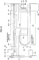
- FIG. 1 is a perspective view of external appearance of the example of the liquid discharging head.
- FIG. 2A is a cross-sectional view of a part of an example of the liquid discharging head, which is viewed from a direction (i.e., a transverse direction of a liquid chamber) orthogonal to a direction in which the nozzles are aligned.
- FIG. 3 is a cross-sectional view of a part of the example of the liquid discharging head, which is viewed from a direction (i.e., longitudinal direction of a liquid chamber) parallel to the direction in which the nozzles are aligned.
- the part of the liquid discharging head illustrated in FIG. 2A is one side (i.e., the right side, in FIG. 2A ) of the liquid discharging head, which is formed along the direction orthogonal to the direction in which the nozzles are aligned. That is to say, in actuality, the liquid discharging head has another side (i.e., the left side) configured to be symmetrical or almost symmetrical with respect to the surface orthogonal to the paper surface of FIG. 2A , such that the said another side is formed to be joined with the part illustrated in FIG. 2A .
- FIG. 4A , FIG. 14A , and FIG. 15A also have similar configurations.
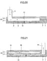
- FIG. 20 is a cross-sectional view taken along A-A' illustrated in each of FIG. 2A and 2B .
- FIG. 21 is a cross-sectional view taken along B-B' illustrated in FIG. 2A and 2B .
- the liquid discharging head includes a nozzle plate 1, a channel plate 2, and a diaphragm member 3 as a wall surface member, which are joined to form layers.
- the liquid discharging head further includes a piezoelectric actuator 11 for causing displacement of the diaphragm member 3, a common liquid chamber member 20, and a cover 29. Note that illustration of the cover 29 is omitted in each of the drawings following FIG. 2A , for convenience in explanation.
- the nozzle plate 1 includes multiple nozzles 4 from which liquid is discharged.
- the channel plate 2 there are individual liquid chambers 6 that lead to the nozzles 4, respectively, fluid resistance portions 7 that lead to the individual liquid chambers 6, respectively, and a liquid introduction portion (i.e., channel) 8 that leads to the fluid resistance portions 7.
- the diaphragm member 3 includes filter portions 9 as openings, through which the liquid introduction portion 8 and a common liquid chamber 10 formed in the common liquid chamber member 20 are connected.
- the diaphragm member 3 is a wall surface member which is formed to be a wall surface of individual liquid chambers 6 of the channel plate 2.
- the diaphragm member 3 is configured to have a two-layer structure, which is simply an example and the diaphragm member 3 is not limited to have the structure.
- the diaphragm member 3 includes the first layer formed as a thin portion, which is arranged closer to the channel plate 2, and the second layer formed as a thick portion. Deformable vibration areas 30 are formed on the first layer at sections that correspond to the individual liquid chamber 6, respectively.
- the piezoelectric actuator 11 which includes an electromechanical conversion element as a driving unit (i.e., an actuator unit or a pressure generating unit) for deforming the vibration areas 30 of the diaphragm member 3, is disposed on a surface of the diaphragm member 3 opposite to the individual liquid chambers 6.
- a driving unit i.e., an actuator unit or a pressure generating unit
- the piezoelectric actuator 11 includes a piezoelectric member 12 that is joined to a base member 13. Further, the piezoelectric member 12 is in a comb-teeth shape, having a desired number of pillar-shaped piezoelectric elements 12A and 12B that are formed at predetermined intervals in grooving by means of half-cut dicing (cf. FIG. 3 ).
- the piezoelectric element 12A of the piezoelectric member 12 is driven in accordance with application of a driving waveform, and the piezoelectric element 12B of the piezoelectric member 12 is simply used as a support to which no driving waveform is applied.
- all of the piezoelectric elements 12A and 12B may be used as piezoelectric elements that are driven by driving waveforms.
- the piezoelectric element 12A is joined to a convex portion 30a, which is an island-shaped thick portion formed on a vibration area 30 of the diaphragm member 3 (cf. FIG. 3 ). Further, the piezoelectric element 12B is joined to a convex portion 30b which is a thick portion formed on the diaphragm member 3.
- the piezoelectric member 12 includes piezoelectric layers and internal electrodes that are alternately disposed to form layers. Further, the internal electrodes are drawn out of an end surface to form external electrodes, to which a flexible wiring member 15 is connected (cf. FIG. 2A ).
- the common liquid chamber member 20 includes the common liquid chamber 10 to which liquid is supplied from a supply tank and a main tank, which are described below with reference to FIG. 22 , and includes the circulation common liquid chamber 50.
- a channel member 40 which includes the channel plate 2 and the diaphragm member 3, there is a fluid resistance portion 51, which is formed along the surface of the channel plate 2, that leads to each of individual liquid chambers 6; a circulation channel 52; and a circulation channel 53, which is formed along the thickness direction of the channel member 40, that leads to the circulation channel 52.
- the circulation channel 53 leads to the circulation common liquid chamber 50.
- liquid discharging head is provided with such a configuration as described above, for example, when voltage applied to a piezoelectric element 12A is decreased to be lower than a reference voltage, which causes the piezoelectric element 12A to contract, a vibration area 30 of the diaphragm member 3 is elevated, such that an individual liquid chamber 6 is enlarged in volume. Consequently, liquid flows into the individual liquid chamber 6 (cf. FIG. 3 ).
- the method of driving the liquid discharging head is not limited to the above example (i.e., what may be termed a "pull to push discharge” method); what is termed a “pull discharge” method or a “push discharge” method may be used, by changing the way of applying a drive waveform.
- the channel member 40 includes the channel plate 2 and the diaphragm member 3 formed as a wall surface member.
- the common liquid chamber member 20 includes a first common liquid chamber member 21 and a second common liquid chamber member 22.
- the first common liquid chamber member 21 is joined to the diaphragm member 3 of the channel member 40.
- the second common liquid chamber member 22 is joined to the upper part of the first common liquid chamber member 21, as illustrated in FIG. 2A , to form layers.
- the first common liquid chamber member 21 includes a downstream common liquid chamber 10A, which is a part of the common liquid chamber 10, that leads to the liquid introduction portion 8 and includes a circulation common liquid chamber 50 that leads to the circulation channel 53.
- the second common liquid chamber member 22 includes an upstream common liquid chamber 10B, which is the remainder of the common liquid chamber 10.
- the downstream common liquid chamber 10A which is a part of the common liquid chamber 10, and the circulation common liquid chamber 50 are arranged side by side in the direction (i.e., the transverse direction in FIG. 2A ) orthogonal to the direction in which the nozzles are aligned.
- the circulation common liquid chamber 50 is covered by the common liquid chamber 10 from a surface opposite (i.e., the upward direction in FIG. 2A ) to the direction in which liquid is discharged from the nozzles 4. Further, the circulation common liquid chamber 50 is covered by the common liquid chamber 10 from one of surfaces facing the direction (i.e., the leftward direction in FIG. 2A ) orthogonal to both the direction in which liquid is discharged from the nozzles 4 and the direction in which the multiple nozzles 4 are aligned. As illustrated in FIG. 2A , the positional relation between the circulation common liquid chamber 50 and the common liquid chamber member 20 may be described such that the circulation common liquid chamber 50 occupies a part of space in the common liquid chamber member 20. Preferably, the circulation common liquid chamber 50 is included in the common liquid chamber member 20.
- the common liquid chamber member 20 (or more specifically, the first common liquid chamber member 21), in which the circulation common liquid chamber 50 is formed, is joined to the above surface of the channel member 40 as illustrated in FIG. 2A .
- dimension (or size) of the circulation common liquid chamber 50 is not restrained by dimensions necessary for the channel including the individual liquid chamber 6, the fluid resistance portion 7, and the liquid introduction portion 8, which are formed in the channel member 40.
- the circulation common liquid chamber 50 and a part of the common liquid chamber 10 are arranged side by side in the transverse direction as illustrated in FIG. 2A .
- the circulation common liquid chamber 50 and the common liquid chamber member 20 are in a relation that may be described such that the circulation common liquid chamber 50 occupies a part of space in the common liquid chamber member 20. Accordingly, width of the head with respect to the direction (i.e., the transverse direction in FIG. 2A ) orthogonal to the direction in which the nozzles are aligned can be short, and therefore a size increase of the liquid discharging head can be avoided.
- FIG. 22 is a block diagram illustrating an example of the liquid circulation system using the liquid discharging head according to the first embodiment.
- the liquid circulation system includes a main tank 1001, the liquid discharging head 1002 according to the above-described first embodiment, a supply tank 1003, a circulation tank 1004, a compressor 1005, a vacuum pump 1006, liquid delivering pumps 1007 and 1008, a regulator (R) 1009, a supply-side pressure sensor 1010, and a circulation-side pressure sensor 1011.
- the main tank 1001, the supply tank 1003, the circulation tank 1004, the compressor 1005, the vacuum pump 1006, the liquid delivering pumps 1007 and 1008, the regulator (R) 1009, the supply-side pressure sensor 1010 and the circulation-side pressure sensor 1011 are included in a supply-circulation mechanism 494, which is described below with reference to FIG. 16 .
- the supply-side pressure sensor 1010 is arranged between the supply tank 1003 and the liquid discharging head 1002, and is connected to a supply channel that leads to a supply port 71 (cf. FIG. 1 ) of the liquid discharging head 1002.
- the circulation-side pressure sensor 1011 is arranged between the liquid discharging head 1002 and the circulation tank 1004, and is connected to a circulation channel that leads to a circulation port 81 (cf. FIG. 1 ) of the liquid discharging head 1002.
- One end of the circulation tank 1004 is connected to the supply tank 1003 via the first liquid delivering pump 1007, and another end of the circulation tank 1004 is connected to the main tank 1001 via the second liquid delivering pump 1008.
- liquid flows from the supply tank 1003 to the liquid discharging head 1002 via the supply port 71, and is ejected into the circulation tank 1004 via the circulation port 81. Furthermore, liquid is delivered from the circulation tank 1004 to the supply tank 1003 via the first liquid delivering pump 1007, such that liquid circulates.
- the compressor 1005 is connected to the supply tank 1003.
- the compressor 1005 is controlled, such that the supply-side pressure sensor 1010 detects a predetermined value of positive pressure.
- the vacuum pump 1006 is connected to the circulation tank 1004.
- the vacuum pump 1006 is controlled, such that the circulation-side pressure sensor 1011 detects a predetermined value of negative value. Accordingly, negative pressure applied to a meniscus of a nozzle 4 can be kept stable, while liquid flowing through the liquid discharging head 1002 is circulated.
- the circulation tank 1004 is replenished with liquid from the main tank 1001 via the second liquid delivering pump 1008.
- Timing of liquid replenishment from the main tank 1001 to the circulation tank 1004 may be controlled, based on a detection result of a liquid surface sensor, etc., provided inside the circulation tank 1004, such that liquid replenishment is conducted when liquid surface of ink inside the circulation tank 1004 gets lower than a predetermined level.
- the supply port 71 that leads to the common liquid chamber 10 and the circulation port 81 that leads to the circulation common liquid chamber 50 are formed on ends of the common liquid chamber member 20.
- the supply port 71 and the circulation port 81 are respectively connected via tubes to the supply tank 1003 and the circulation tank 1004, which store liquid (cf. FIG. 22 ). Then, liquid stored in the supply tank 1003 is supplied to an individual liquid chamber 6, through the supply port 71, the common liquid chamber 10, the liquid introduction portion 8, and the fluid resistance portion 7 (cf. FIG 2A and FIG. 3 ).
- liquid inside an individual liquid chamber 6 is discharged from a nozzle 4 by driving the piezoelectric member 12, liquid remained inside the individual liquid chamber 6 without being discharged is partially or entirely circulated to the circulation tank 1004 through the fluid resistance portion 51, the circulation channels 52 and 53, the circulation common liquid chamber 50, and the circulation port 81 (cf. FIG. 2A , FIG. 3 , FIG. 20, and FIG. 21 ).
- circulation of liquid is preferred to be performed, not only while the liquid discharging head is operating, but also while the liquid discharging head is not operating. Circulation of liquid while the liquid discharging head is not operating helps liquid inside an individual liquid chamber 6 be always refreshed and helps components contained in liquid avoid from being agglomerated or accumulated.
- the liquid discharging head according to the first embodiment is employed as the liquid discharging head 1002 according to the first embodiment of a liquid discharging head.
- the liquid discharging head 1002 in the example of the liquid circulation system may be a liquid discharging head according to a modification example of the liquid discharging head of the first embodiment or a liquid discharging head according to each of other embodiments and modification examples of the embodiments.
- FIG. 2B is a cross-sectional view of a part of a modification example of the above-described liquid discharging head according to the first embodiment of the present invention, which is viewed from the direction (i.e., the transverse direction of a liquid chamber) orthogonal to the direction in which the nozzles are aligned.
- the liquid discharging head according to the first embodiment and the modification of the liquid discharging head according to the first embodiment are almost the same in terms of configurations and functions.
- constituent elements that are the same as or correspond to constituent elements of the liquid discharging head according to the first embodiment are assigned the same reference signs as assigned to the constituent elements of the liquid discharging head according to the first embodiment, so as to omit explanation.
- FIG. 4A is a cross-sectional view of a part of the liquid discharging head, which is viewed from the direction (i.e., the transverse direction of a liquid chamber) orthogonal to the direction in which the nozzles are aligned.
- FIG. 5 is a plan view of an example of a nozzle plate according to each of the liquid discharging head and a modification example of the liquid discharging head.
- FIGS. 6A through 6F are plan views of an example of each member included in the channel member 40 of the liquid discharging head according to the second embodiment.
- FIGS. 7A and 7B are plan views of an example of each member included in the common liquid chamber member 20 of the liquid discharging head, and also of an example of each member included in the common liquid chamber member 20 of a modification example of the liquid discharging head as well.
- the second embodiment and, for example, the above-described first embodiment are almost the same in terms of configurations and functions.
- the following description mainly explains parts that differ from the first embodiment, and explanations of parts that are the same as those in the first embodiment are omitted, as appropriate.
- multiple plate members (i.e., thin layer members) 41 through 45 are layered on the nozzle plate 1 and joined to form the channel plate 2.
- the plate members 41 through 45 and the diaphragm member 3 are layered and joined to form the channel member 40.
- the common liquid chamber member 20 includes the first common liquid chamber member 21 and the second common liquid chamber member 22.
- through-groove portions i.e., a through-hole in a shape of a groove; hereinafter meaning the same
- through-groove portions 51a and 52a to respectively form fluid resistance portions 51 and circulation channels 52 are formed on the plate member 41, which is included in the channel plate 2.
- through-parts 6b to form individual liquid chambers 6, and through-groove portions 52b to form circulation channels 52 are formed on the plate member 42.
- plate-shaped through-groove portions 6c to form individual liquid chambers 6, and through-groove portions 53a, whose longitudinal direction is the direction in which the nozzles are aligned, to form circulation channels 53 are formed on the plate member 43.
- through-groove portions 6d to form individual liquid chambers 6, through-groove portions 7a to become fluid resistance portions 7, through-groove portions 8a to form liquid introduction portions 8, and through-groove portions 53b, whose longitudinal direction is the direction in which the nozzles are aligned, to form circulation channels 53 are formed on the plate member 44.
- through-groove portions 6e to form individual liquid chambers 6, and through-groove portions 8b, whose longitudinal direction is the direction in which the nozzles are aligned, to form liquid introduction portions 8 (i.e., to become liquid chambers that are downstream of filters) are formed on the plate member 45.
- through-groove portions 53c, whose longitudinal direction is the direction in which the nozzles are aligned, to form circulation channels 53 are formed on the plate member 45.
- the vibration areas 30, the filter portions 9, and through-groove portions 53d, whose longitudinal direction is the direction in which the nozzles are aligned, to form circulation channels 53 are formed on the diaphragm member 3.
- a through-hole 25a provided for a piezoelectric actuator, through-groove portions 10a to become downstream common liquid chambers 10A, and groove-parts 50a with undersurfaces to become circulation common liquid chambers 50 are formed on the first common liquid chamber member 21 included in the common liquid chamber member 20.
- a through-hole 25b provided for a piezoelectric actuator, and groove-parts 10b to become upstream common liquid chambers 10B are formed on the second common liquid chamber member 22.
- through-holes 71a to become supply port portions which connect an end of each common liquid chamber 10 in the direction in which the nozzles are aligned with a corresponding supply port (or liquid port) 71, are formed on the second common liquid chamber member 22.
- through-holes 81a and 81b which connect another end (i.e., the opposite end of the through-holes 71a) of each circulation common liquid chamber 50 in the direction in which the nozzles are aligned with a corresponding circulation port (or liquid port) 81, are formed on the first common liquid chamber member 21 and the second common liquid chamber member 22.
- FIG. 7A and 7B groove-parts with undersurfaces other than the above-mentioned groove-parts 50a with undersurfaces are illustrated with hatching (which may be also referred to as "cross-hatching") similarly to the above-mentioned groove-parts 50a with undersurfaces (in the following drawings as well).
- complex channels can be formed in a relatively easy way, such that multiple plate members are layered and joined to form the channel member 40.
- FIG. 4B is a cross-sectional view of a part of a modification example of the liquid discharging head according to the above-described second embodiment of the present invention, which is viewed from the direction (i.e., the transverse direction of a liquid chamber) orthogonal to the direction in which the nozzles are aligned.
- FIGS. 6G through 6L are plan views of an example of each member included in the channel member 40 of the modification example of the liquid discharging head.
- through-groove portions 6a to form individual liquid chambers 6, and through-groove portions 51a and 52a to respectively form fluid resistance portions 51 and circulation channels 52 are formed on the plate member 41, which is included in the channel plate 2.
- plate portions 6b' to form individual liquid chambers 6, and through-groove portions 52b to form circulation channels 52 are formed on the plate member 42.
- plate portions 6c' to form individual liquid chambers 6, and through-groove portions 53a' to form circulation channels 53 are formed on the plate member 43.
- through-groove portions 6d to form individual liquid chambers 6, through-groove portions 7a to become fluid resistance portions 7, through-groove portions 8a to form liquid introduction portions 8, and through-groove portions 53b' to form circulation channels 53 are formed on the plate member 44.
- through-groove portions 6e to form individual liquid chambers 6, and through-groove portions 8b, whose longitudinal direction is the direction in which the nozzles are aligned, to become liquid introduction portions 8 (i.e., to become liquid chambers that are downstream of filters) are formed on the plate member 45.
- through-groove portions 53c' to form circulation channels 53 are formed on the plate member 45.
- vibration areas 30, filter portions 9, and through-groove portions 53d' to form circulation channels 53 are formed on the diaphragm member 3.
- the third embodiment and, for example, each of the liquid discharging head according to the above-described second embodiment and the modification of the liquid discharging head according to the second embodiment are almost the same in terms of configurations and functions.
- the following description mainly explains parts that differ from the liquid discharging head according to the second embodiment and the modification of the liquid discharging head according to the second embodiment, and explanations of parts that are the same as those in the liquid discharging head according to the second embodiment and the modification of the liquid discharging head according to the second embodiment are omitted, as appropriate.
- FIGS. 8A and 8B are plan views of examples of a common liquid chamber member 20 of a liquid discharging head according to the third embodiment. Note that FIG. 8A is a plan view of an example of the first common liquid chamber member 21, and FIG. 8B is a plan view of an example of the second common liquid chamber member 22.
- through-holes 81a to be connected to liquid ports 81 are formed on both ends of the circulation common liquid chamber 50 in the direction in which the nozzles are aligned.
- through-holes 81b to form the liquid ports 81 are formed on both ends of the circulation common liquid chamber 50 in the direction in which the nozzles are aligned, and through-holes 71a to be connected to liquid ports 71 are formed on both ends of each of common liquid chambers 10 in the direction in which the nozzles are aligned.
- the fourth embodiment and, for example, the above-described third embodiment are almost the same in terms of configurations and functions.
- the following description mainly explains parts that differ from the third embodiment, and explanations of parts that are the same as those in the third embodiment are omitted, as appropriate.
- FIGS. 9A and 9B are plan views of the first common liquid chamber member 21 of the liquid discharging head in each manufacturing process.
- groove-parts 50a to become circulation common liquid chambers 50 are formed by half-etching, and through-groove portions 10a to become downstream common liquid chambers 10A are formed by full-etching on the first common liquid chamber member 21
- through-holes 81a are made through the above-described half-etched parts in laser processing, so as to form parts 81b that correspond to liquid ports 81.
- each common liquid chamber 10 i.e., downstream common liquid chamber 10A
- each circulation common liquid chamber 50 are formed with high accuracy.
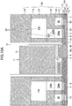
- FIG. 10A is a cross-sectional view of an example of the liquid discharging head, which is viewed from the direction (i.e., the transverse direction of a liquid chamber) orthogonal to the direction in which the nozzles are aligned.
- FIGS. 11A through 11D are plan views of each member included in the common liquid chamber member of the liquid discharging head, and also of each member included in the common liquid chamber member of a modification example of the liquid discharging head.
- the fifth embodiment and, for example, the second embodiment as described above with reference to FIG. 4A , etc., are almost the same in terms of configurations and functions.
- the following description mainly explains parts that differ from the second embodiment, and explanations of parts that are the same as those in the second embodiment are omitted, as appropriate.
- FIG. 10A is a cross-sectional view of an example of the liquid discharging head viewed from the direction (i.e., the transverse direction of a liquid chamber) orthogonal to the direction in which the nozzles are aligned, but both of left and right halfs are illustrated. Note that, although the right half illustrated in FIG. 10A has a cross-section along a surface of an individual liquid chamber 6, etc., similarly to FIG. 2A , etc., the left half has a cross-section along a surface of a dividing wall part 2a (cf. FIG. 2A ) that divides individual liquid chambers 6 apart.
- a dividing wall part 2a cf. FIG. 2A
- the nozzles 4 are formed in a zigzag manner, as described above with reference to FIG. 5 .
- positions of individual liquid chambers 6 along the direction in which the nozzles are aligned are unmatched between the right and left halfs (illustrated in FIG. 10A ) by almost a half pitch of the individual liquid chambers 6. Accordingly, for example, as illustrated in FIG.
- the right half has a cross-section along a surface of an individual liquid chamber 6, and the left half has a cross-section along a surface of a dividing wall part 2a that divides individual liquid chambers 6 apart.
- FIG. 10B The same applies to FIG. 10B .
- a common liquid chamber member 120 includes at least three members that are joined to be layers: a first common liquid chamber member 121, a second common liquid chamber member 122, a third common liquid chamber member 123, and a housing member 124 that functions also as a fourth common liquid chamber member. That is to say, a common liquid chamber member 120 includes four members 121 through 124 in total. Note that, similarly to the second common liquid chamber member 22 in each of the above embodiments, the third common liquid chamber member 123 may be replaced by a member having a unified wall part, which is otherwise formed by the housing member 124.
- the first common liquid chamber member 121 is an example of "one of two members arranged in series in the direction of layering, which are among the three members".
- a through-hole 125a provided for a piezoelectric actuator and through-groove portions 110a which are through-parts to become parts 10Aa (cf. FIG. 10A ) of downstream common liquid chambers 10A, are formed on the first common liquid chamber member 121.
- through-groove portions 150a which are through-parts to become circulation common liquid chambers 50, are formed on the first common liquid chamber member 121.
- the second common liquid chamber member 122 is an example of "another one of two members arranged in series in the direction of layering, which are among the three members". As illustrated in FIG. 11B , a through-hole 125b provided for a piezoelectric actuator and through-groove portions 110b, which are through-parts to become parts 10Ab (cf. FIG. 10A ) of downstream common liquid chambers 10A, are formed on the second common liquid chamber member 122. Furthermore, the second common liquid chamber member 122 is provided as a wall part (or a wall surface) 150 of the circulation common liquid chamber 50.
- a through-hole 125d provided for a piezoelectric actuator is formed on the housing member 124.
- the housing member 124 is provided as a wall part (or a wall surface) 110 of upstream common liquid chambers 10B.
- through-holes 171a to become supply port portions that connect an end of each common liquid chamber 10 in the direction in which the nozzles are aligned and a corresponding supply port (or liquid port; cf. FIG. 1 ) 71 are formed on the housing member 124.
- through-holes 181a, 181b, 181c, and 181d that connect another end (i.e., the opposite end of the through-holes 171a) of each circulation common liquid chamber 50 in the direction in which the nozzles are aligned with a corresponding circulation port (or liquid port; cf. FIG. 1 ) 81 are formed on the first common liquid chamber member 121, the second common liquid chamber member 122, the third common liquid chamber member 123, and the housing member 124.
- reference holes 143 and elliptical holes 144 are provided on the first common liquid chamber member 121, the second common liquid chamber member 122, the third common liquid chamber member 123, and the housing member 124, as alignment marks for assembly.
- FIG. 10B is a cross-sectional view of a part of a modification example of the liquid discharging head according to the above-described fifth embodiment of the present invention, which is viewed from the direction (i.e., the transverse direction of a liquid chamber) orthogonal to the direction in which the nozzles are aligned.
- the modification example of the liquid discharging head according to the fifth embodiment and the liquid discharging head according to the fifth embodiment described above have almost the same configurations and functions.
- constituent elements that are the same as or correspond to constituent elements of the liquid discharging head according to the fifth embodiment are assigned the same reference signs as assigned to the constituent elements of the liquid discharging head according to the fifth embodiment, so as to omit explanation.
- FIG. 12 is a plan view of a first common liquid chamber member of the liquid discharging head
- FIG. 13 is an enlarged view of a part of FIG. 12 .
- the sixth embodiment and, for example, each of the fifth embodiment and the modification example of the liquid discharging head according to the fifth embodiment as described above with reference to FIGS. 10A and 10B and FIGS. 11A through 11D are almost the same in terms of configurations and functions.
- the following description mainly explains parts that differ from the fifth embodiment and the modification example of the liquid discharging head according to the fifth embodiment, and explanations of parts that are the same as those in the fifth embodiment and the modification example of the liquid discharging head according to the fifth embodiment are omitted, as appropriate.
- alignment marks 145 are provided at two positions on the first common liquid chamber member 121 of the above-described fifth embodiment, instead of the reference hole 143 and the elliptical hole 144.
- Each of the alignment marks includes a reference hole 145a and slit holes 145b that are arranged around the reference hole 145a at four positions in the same distance from each other.
- Alignment marks 145 are similarly provided on the second common liquid chamber member 122, the third common liquid chamber member 123, and the housing member 124.
- FIG. 14A is a cross-sectional view of a part of an example of the liquid discharging head, which is viewed from the direction (i.e., the transverse direction of a liquid chamber) orthogonal to the direction in which the nozzles are aligned.
- the seventh embodiment and, for example, the fifth embodiment described above with reference to FIG. 10A and FIGS. 11A through 11D are almost the same in terms of configurations and functions.
- the following description mainly explains parts that differ from the fifth embodiment, and explanations of parts that are the same as those in the fifth embodiment are omitted, as appropriate.
- the first common liquid chamber member 121, the second common liquid chamber member 122, and the third common liquid chamber member 123 are joined and layered with positional gaps in the direction (i.e., the transverse direction in FIG. 14A ) orthogonal of the direction in which the nozzles are aligned.
- first common liquid chamber member 121, the second common liquid chamber member 122, and the third common liquid chamber member 123 may be formed in press processing to have such deformation.
- the members 121 through 124 with the deformation are joined, such that ledge parts 146 are created between each of the first common liquid chamber member 121, the second common liquid chamber member 122, the third common liquid chamber member 123, and the housing member 124, due to the deformation.
- the ledge parts 146 are created between each of the first common liquid chamber member 121, the second common liquid chamber member 122, the third common liquid chamber member 123, and the housing member 124. Accordingly, even in a case where adhesive agent 90 used for joining each of the members 121 through 124 is protruded from the joint parts, the protruded adhesive agent 90 is accommodated by the ledge parts 146. Therefore, the adhesive agent 90 is prevented from flowing into the common liquid chamber 10 and then getting solidified, which may cause bubbles to get trapped.
- FIG. 14B is a cross-sectional view of a part of a modification example of the liquid discharging head according to the above-described seventh embodiment, which is viewed from the direction (i.e., the transverse direction of a liquid chamber) orthogonal to the direction in which the nozzles are aligned.
- the modification example of the liquid discharging head according to the seventh embodiment and the liquid discharging head according to the seventh embodiment described above are almost the same in terms of configurations and functions.
- constituent elements that are the same as or correspond to constituent elements of the liquid discharging head according to the seventh embodiment are assigned the same reference signs as assigned to the constituent elements of the liquid discharging head according to the seventh embodiment, so as to omit explanation.
- FIG. 15A is a cross-sectional view of a part of an example of the liquid discharging head, which is viewed from the direction (i.e., the transverse direction of a liquid chamber) orthogonal to the direction in which the nozzles are aligned.
- the eighth embodiment and, for example, the fifth embodiment described above with reference to FIG. 10A and FIGS. 11A through 11D are almost the same in terms of configurations and functions.
- the following description mainly explains parts that differ from the fifth embodiment, and explanations of parts that are the same as those in the fifth embodiment are omitted, as appropriate.
- width of the second common liquid chamber member 122 which is between the first common liquid chamber member 121 and the third common liquid chamber member 123, is configured to be narrower than widths of the first common liquid chamber member 121 and the third common liquid chamber member 123, with respect to the direction (i.e., the transverse direction in FIG. 15A ) orthogonal to the direction in which the nozzles are aligned.
- ledge parts 146 are created between each of the first common liquid chamber member 121, the second common liquid chamber member 122, and the third common liquid chamber member 123. Therefore, similarly to the above-described seventh embodiment, adhesive agent 90 protruded in a joining process are accommodated by the ledge parts 146. Consequently, similarly to the seventh embodiment, the adhesive agent 90 is prevented from flowing into the common liquid chamber 10 and then becoming solidified, which may cause bubbles to get trapped.
- width of the second common liquid chamber member 122 may be configured to be wider than widths of the first common liquid chamber member 121 and the third common liquid chamber member 123, with respect to the direction (i.e., the transverse direction in FIG. 15A ) orthogonal to the direction in which the nozzles are aligned.
- ledge parts are created between each of the first common liquid chamber member 121, the second common liquid chamber member 122, and the third common liquid chamber member 123.
- adhesive agent 90 protruded in a joining process is accommodated by the ledge parts, such that the adhesive agent 90 is prevented from flowing into the common liquid chamber 10 and then becoming solidified, which may cause bubbles to get trapped.
- FIG. 15B is a cross-sectional view of a part of a modification example of the liquid discharging head according to the above-described eighth embodiment of the present invention, which is viewed from the direction (i.e., the transverse direction of a liquid chamber) orthogonal to the direction in which the nozzles are aligned.
- the modification example of the liquid discharging head according to the eighth embodiment and the liquid discharging head according to the eighth embodiment described above have almost the same configurations and functions.
- constituent elements that are the same as or correspond to constituent elements of the liquid discharging head according to the eighth embodiment are assigned the same reference signs as assigned to the constituent elements of the liquid discharging head according to the eighth embodiment, so as to omit explanation.
- the modification example of the liquid discharging head according to the eighth embodiment is almost the same as each modification example of the liquid discharging head according to the first embodiment, the second embodiment, the fifth embodiment or the seventh embodiment, in terms of configurations of the channel plate 2.
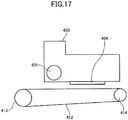
- FIG. 16 is a plan view of a part of the device for discharging liquid
- FIG. 17 is a side view of a part of the device for discharging liquid.
- the device for discharging liquid is a serial type device in which a main-scanning movement mechanism 493 causes a carriage 403 to reciprocate in a main-scanning direction.
- the main-scanning movement mechanism 493 includes a guide member 401, a main-scanning motor 405, a timing belt 408, etc.
- the guide member 401 is disposed across right and left side plates 491A and 491B, to support the carriage 403 in a movable manner.
- the main-scanning motor 405 enables the carriage 403 to reciprocate in the main-scanning direction via the timing belt 408 that extends over a driving pulley 406 and a driven pulley 407.
- the above carriage 403 is mounted with a liquid discharging head 404 according to an embodiment or a modification example of the embodiment described above.
- the liquid discharging head 404 discharges liquid of respective colors of, for example, yellow (Y), cyan (C), magenta (M), and black (K).
- the liquid discharging head 404 is provided with a nozzle line that includes multiple nozzles aligning in a sub-scanning direction, which is orthogonal to the main-scanning direction; the multiple nozzles are installed on the liquid discharging head 404 with the discharging directions downwards.
- a supply-circulation mechanism 494 which is described above with reference to FIG. 22 , for supplying the liquid discharging head 404 with liquid stored outside the liquid discharging head 404.
- every element included in the liquid circulation system described above with reference to FIG. 22 except for the liquid discharging head 404 (1002, in FIG. 22 ), belongs to the supply-circulation mechanism 494. Liquid is delivered from the supply-circulation mechanism 494 to the liquid discharging head 404 via a tube 456.
- the device is provided with a conveyance mechanism 495 to convey a sheet 410.
- the conveyance mechanism 495 includes a conveyer belt 412 as a conveyance means and includes a sub-scanning motor 416 to drive the conveyer belt 412.
- the conveyer belt 412 attracts and conveys the sheet 410 to a position that faces the liquid discharging head 404.
- the conveyer belt 412 is an endless belt that extends over a conveyance roller 413 and a tension roller 414. To attract, as mentioned above, electrostatic adsorption, air absorption, etc., may be employed.
- the conveyer belt 412 performs circular movement in the sub-scanning direction as the sub-scanning motor 416 drives, via a timing belt 417 and a timing pulley 418, the conveyance roller 413 to rotate.
- a maintenance/recovery mechanism 420 is arranged by the conveyer belt 412 near one of the ends of the main-scanning direction of the carriage 403, for conducting maintenance and recovery for the liquid discharging head 404.
- the maintenance/recovery mechanism 420 for example, includes a cap member 421 for capping the nozzle surface (i.e., the surface having the nozzles 4) of the liquid discharging head 404 and includes a wiper member 422 for wiping the nozzle surface.
- the main-scanning movement mechanism 493, the supply-circulation mechanism 494, the maintenance/recovery mechanism 420, and the conveyance mechanism 495 are disposed on a case including the side plates 491A and 491B and a back plate 491C.
- a sheet 410 is fed onto and attracted by the conveyer belt 412 and is conveyed in the sub-scanning direction in accordance with circular movement of the conveyer belt 412.
- the liquid discharging head 404 is driven, based on an image signal, while the carriage 403 is moved in the main-scanning direction, so that liquid is discharged onto the sheet 410 to form an image when the sheet 410 is not moving.
- the device is capable of stably forming a high quality image.
- FIG. 18 is a plan view of a part of the unit.
- the liquid discharging unit includes: the case part including the side plates 491A and 491B and the back plate 491C; the main-scanning movement mechanism 493; the carriage 403; and a liquid discharging head 404 according to an above-described embodiment or modification example of the embodiment.
- At least one of the above-described maintenance/recovery mechanism 420 and the supply-circulation mechanism 494 may be additionally mounted, for example, on the side plate 491B of the liquid discharging unit.
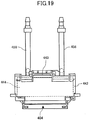
- FIG. 19 is a front view of a part of the liquid discharging unit.
- the liquid discharging unit includes a liquid discharging head 404 according to an embodiment or a modification example of the embodiment described above, which is provided with a channel part 444, and includes tubes 456 connected to the channel part 444.
- channel part 444 is arranged inside a cover 442.
- the supply-circulation mechanism 494 may be included.
- a connector 443 that enables electrical connection with the liquid discharging head 404 is provided on an upper portion of the channel part 444.
- the "device for discharging liquid” includes a liquid discharging head or a liquid discharging unit; the “device for discharging liquid” drives the liquid discharging head to discharge liquid.
- the “device for discharging liquid” is not limited to be a device that is capable of discharging liquid to something that liquid can adhere to; the “device for discharging liquid” may be a device for discharging liquid into gas or liquid fluid.
- the "device for discharging liquid” may include means that relates to feeding, conveying, and ejecting something that liquid can adhere to, and moreover may include a pre-processing device, a post-processing device, etc.
- the "device for discharging liquid” may be an image forming device that discharges ink to form an image on a sheet, and may be a solid modeling device (i.e., a three-dimensional modeling device) that discharges modeling liquid to a powder layer formed of powdery material to produce a solid model (i.e., a three-dimensional model).
- a solid modeling device i.e., a three-dimensional modeling device
- the "device for discharging liquid” is not limited to a device that discharges liquid for visualizing significative images such as letters and figures.
- the "device for discharging liquid” may be a device that forms a pattern, etc., that is not significative by itself, and may be a device that produces a three dimensional model.
- the above-mentioned "something that liquid can adhere to” means to be something that liquid can adhere to at least temporarily.
- Material of the "something that liquid can adhere to” may be anything such as paper, string, fiber, cloth, leather, metal, plastic, glass, wood, or ceramics, as far as being something that liquid can adhere to at least temporarily.
- liquid may be ink, processing liquid, DNA samples, resists, pattern materials, binding agents, modeling liquid, etc.
- the "device for discharging liquid” may be a serial type device in which a liquid discharging head is moved, and may be a line type device in which a liquid discharging head is not moved.
- the “device for discharging liquid” may be a processing liquid applying device that discharges processing liquid to a sheet to apply the processing liquid to the sheet surface for improving quality of the sheet surface, and may be a spray granulation device that sprays composition liquid containing raw materials dispersed inside of the liquid through a nozzle to granulate the raw materials into micro-particles.
- the “liquid discharging unit” may be an assembly of parts related to discharging liquid, in which functional parts or mechanisms are unified with a liquid discharging head.
- the “liquid discharging unit” may be a combination of a liquid discharging head and at least one of a carriage, a supply-circulation mechanism, a maintenance/recovery mechanism, and a main-scanning movement mechanism.
- unified may mean, for example, that a liquid discharging head and functional parts or mechanisms are fastened, adhered, engaged, etc., so as to be fixed to each other and that one is supported by the other in a movable manner.
- a liquid discharging head and functional parts or mechanisms may be configured to be attachable to or detachable from each other.
- the liquid discharging unit may be a unit in which a liquid discharging head and a supply-circulation mechanism are unified. Furthermore, the liquid discharging unit may be a unit in which a liquid discharging head and a supply-circulation mechanism are unified through tubes, etc., that connect each other. Note that such a liquid discharging unit may be additionally provided with a unit including a filter disposed between a liquid discharging head and a supply-circulation mechanism.
- the liquid discharging unit may be a unit in which a liquid discharging head and a carriage are unified.
- the liquid discharging unit may be a unit in which a liquid discharging head is unified with a scanning movement mechanism, such that the liquid discharging head is supported in a movable manner by a guide member that is configured to be a part of the scanning movement mechanism.
- the liquid discharging unit may be a unit in which a liquid discharging head, a carriage, and a main-scanning movement mechanism are unified.
- the liquid discharging unit may be a unit in which a liquid discharging head, a carriage, and a maintenance/recovery mechanism are unified, such that a cap member that is a part of the maintenance/recovery mechanism is fixed to the carriage that is provided with the liquid discharging head.
- the liquid discharging unit may be a unit in which a liquid discharging head is unified with a supply-circulation mechanism or a channel part, such that tubes are connected to the liquid discharging head, which is provided with the supply-circulation mechanism or the channel part.
- the main-scanning movement mechanism may be simply a guide member.
- a supply-circulation mechanism may be simply tubes or a loading unit.
- the pressure generating unit employed for the "liquid discharging head".
- the pressure generating unit may be a thermal actuator provided with an electricity-heat converting element such as a heating resistor and may be an electrostatic actuator configured with a diaphragm and a counterpart electrode.
Landscapes
- Physics & Mathematics (AREA)
- Optics & Photonics (AREA)
- Particle Formation And Scattering Control In Inkjet Printers (AREA)
- Ink Jet (AREA)
- Engineering & Computer Science (AREA)
- Manufacturing & Machinery (AREA)
Applications Claiming Priority (3)
| Application Number | Priority Date | Filing Date | Title |
|---|---|---|---|
| JP2015000612 | 2015-01-06 | ||
| JP2015096721 | 2015-05-11 | ||
| PCT/JP2015/085574 WO2016111147A1 (ja) | 2015-01-06 | 2015-12-18 | 液体吐出ヘッド、液体吐出ユニット、及び液体を吐出する装置 |
Publications (3)
| Publication Number | Publication Date |
|---|---|
| EP3243663A1 EP3243663A1 (en) | 2017-11-15 |
| EP3243663A4 EP3243663A4 (en) | 2018-01-10 |
| EP3243663B1 true EP3243663B1 (en) | 2019-02-06 |
Family
ID=56355848
Family Applications (1)
| Application Number | Title | Priority Date | Filing Date |
|---|---|---|---|
| EP15877020.6A Active EP3243663B1 (en) | 2015-01-06 | 2015-12-18 | Liquid-discharging head, liquid-discharging unit, and device for discharging liquid |
Country Status (8)
| Country | Link |
|---|---|
| US (7) | US10160226B2 (es) |
| EP (1) | EP3243663B1 (es) |
| JP (4) | JP6428791B2 (es) |
| CN (1) | CN107107616B (es) |
| AU (1) | AU2015375735B2 (es) |
| CA (1) | CA2972858C (es) |
| ES (1) | ES2716122T3 (es) |
| WO (1) | WO2016111147A1 (es) |
Families Citing this family (37)
| Publication number | Priority date | Publication date | Assignee | Title |
|---|---|---|---|---|
| AU2015375735B2 (en) | 2015-01-06 | 2019-02-14 | Ricoh Company, Ltd. | Liquid-discharging head, liquid-discharging unit, and device for discharging liquid |
| JP6486465B2 (ja) * | 2015-05-27 | 2019-03-20 | 京セラ株式会社 | 液体吐出ヘッド、および記録装置 |
| US9925785B2 (en) * | 2015-09-30 | 2018-03-27 | Ricoh Company, Ltd. | Liquid discharge head, liquid discharge device, and liquid discharge apparatus |
| JP6870402B2 (ja) * | 2016-03-16 | 2021-05-12 | 株式会社リコー | インクセット、イエローインク、インク収容容器、インクジェット印刷装置、インクジェット印刷方法 |
| JP6788221B2 (ja) * | 2016-05-26 | 2020-11-25 | 株式会社リコー | インクの製造方法 |
| JP6686805B2 (ja) * | 2016-09-05 | 2020-04-22 | コニカミノルタ株式会社 | インクジェットヘッド及びインクジェット記録装置 |
| JP6864860B2 (ja) * | 2016-09-07 | 2021-04-28 | 株式会社リコー | インク、インクジェット印刷装置、インクジェット印刷方法 |
| JP6941269B2 (ja) * | 2016-10-17 | 2021-09-29 | 株式会社リコー | インク吐出装置及びインク吐出方法 |
| JP2018103616A (ja) * | 2016-12-22 | 2018-07-05 | 株式会社リコー | インク、インクジェット印刷装置、及びインクジェット印刷方法 |
| US10179452B2 (en) | 2017-01-10 | 2019-01-15 | Ricoh Company, Ltd. | Liquid discharge head, liquid discharge device, and liquid discharge apparatus |
| JP6999088B2 (ja) | 2017-03-21 | 2022-01-18 | 株式会社リコー | 液体吐出ヘッド、液体吐出ユニット、液体を吐出する装置 |
| JP6897195B2 (ja) * | 2017-03-21 | 2021-06-30 | 株式会社リコー | 液体吐出ヘッド、液体吐出ユニット、液体を吐出する装置 |
| JP7039850B2 (ja) | 2017-03-21 | 2022-03-23 | 株式会社リコー | 液体吐出ヘッド、液体吐出ユニット、液体を吐出する装置 |
| US10399355B2 (en) | 2017-03-21 | 2019-09-03 | Ricoh Company, Ltd. | Liquid discharge head, liquid discharge device, and liquid discharge apparatus |
| JP6938995B2 (ja) | 2017-03-21 | 2021-09-22 | 株式会社リコー | 液体循環装置、液体を吐出する装置 |
| EP3643503B1 (en) * | 2017-06-22 | 2021-07-07 | Konica Minolta, Inc. | Liquid ejection head and liquid ejection device |
| JP6943035B2 (ja) | 2017-06-27 | 2021-09-29 | 株式会社リコー | 液体循環装置、液体を吐出する装置 |
| JP7064168B2 (ja) | 2018-01-26 | 2022-05-10 | 株式会社リコー | 液体を吐出する装置 |
| JP2019130872A (ja) * | 2018-02-02 | 2019-08-08 | 株式会社リコー | 液体吐出ヘッド、液体吐出ユニット、液体を吐出する装置 |
| JP7047454B2 (ja) | 2018-02-23 | 2022-04-05 | 株式会社リコー | 液体吐出ヘッド、液体吐出ユニット、液体を吐出する装置 |
| JP7031376B2 (ja) | 2018-03-04 | 2022-03-08 | 株式会社リコー | 液体吐出ヘッド、液体吐出ユニット、液体を吐出する装置 |
| JP7056287B2 (ja) | 2018-03-22 | 2022-04-19 | ブラザー工業株式会社 | ヘッド |
| US10792920B2 (en) | 2018-05-25 | 2020-10-06 | Ricoh Company, Ltd. | Laminated substrate, liquid discharge head, and liquid discharge apparatus |
| JP7207942B2 (ja) * | 2018-10-23 | 2023-01-18 | キヤノン株式会社 | 液体吐出ヘッド |
| JP7131317B2 (ja) | 2018-11-13 | 2022-09-06 | 株式会社リコー | 液体吐出ヘッド、液体吐出ユニット、液体を吐出する装置 |
| US11040536B2 (en) | 2018-11-28 | 2021-06-22 | Ricoh Company, Ltd. | Liquid discharge head, liquid discharge device, and liquid discharge apparatus |
| JP7266781B2 (ja) * | 2018-11-29 | 2023-05-01 | 株式会社リコー | 液体組成物、インク、インクセット、印刷方法、印刷装置 |
| JP7183809B2 (ja) * | 2019-01-23 | 2022-12-06 | ブラザー工業株式会社 | 液体吐出ヘッド |
| JP7183822B2 (ja) | 2019-01-28 | 2022-12-06 | 株式会社リコー | 液体吐出ヘッド、液体吐出ユニット、液体を吐出する装置 |
| JP7306024B2 (ja) * | 2019-04-01 | 2023-07-11 | ブラザー工業株式会社 | 液体吐出装置 |
| JP7287074B2 (ja) * | 2019-04-10 | 2023-06-06 | ブラザー工業株式会社 | 液体吐出装置 |
| JP7259507B2 (ja) | 2019-04-18 | 2023-04-18 | 株式会社リコー | 液体吐出ヘッド、液体吐出ユニット、液体を吐出する装置 |
| JP7310320B2 (ja) | 2019-06-03 | 2023-07-19 | ブラザー工業株式会社 | 液体吐出ヘッドおよびそれを備える液体吐出装置 |
| JP7342596B2 (ja) | 2019-10-11 | 2023-09-12 | 株式会社リコー | 液体吐出ヘッド、吐出ユニット、液体を吐出する装置 |
| JP7380066B2 (ja) | 2019-10-18 | 2023-11-15 | 株式会社リコー | 液体吐出ヘッド、吐出ユニット、液体を吐出する装置 |
| JP7452004B2 (ja) | 2019-12-25 | 2024-03-19 | 株式会社リコー | 液体吐出ヘッド、吐出ユニット、液体を吐出する装置 |
| JP2022024739A (ja) | 2020-07-28 | 2022-02-09 | 株式会社リコー | 液体吐出ヘッド、液体吐出ユニット及び液体を吐出する装置 |
Family Cites Families (27)
| Publication number | Priority date | Publication date | Assignee | Title |
|---|---|---|---|---|
| JPS5029395B1 (es) | 1968-05-04 | 1975-09-23 | ||
| JPS5029395A (es) | 1973-07-04 | 1975-03-25 | ||
| US5455615A (en) * | 1992-06-04 | 1995-10-03 | Tektronix, Inc. | Multiple-orifice drop-on-demand ink jet print head having improved purging and jetting performance |
| EP0573256B1 (en) * | 1992-06-04 | 1997-03-26 | Tektronix, Inc. | Drop-on-demand ink jet print head having improved purging performance |
| JP3217645B2 (ja) * | 1995-06-30 | 2001-10-09 | キヤノン株式会社 | インクジェット記録装置および該装置におけるインク吐出回復方法 |
| JPH1076650A (ja) | 1996-09-05 | 1998-03-24 | Fuji Xerox Co Ltd | インクジェットプリントヘッドおよびその作製方法 |
| JP3589236B2 (ja) * | 1999-01-29 | 2004-11-17 | セイコーエプソン株式会社 | インクジェット式記録ヘッド及びこれを用いた画像記録装置 |
| EP1024003B1 (en) | 1999-01-29 | 2002-10-16 | Seiko Epson Corporation | Ink jet recording head with improved ink supply channels |
| JP2004098310A (ja) * | 2002-09-05 | 2004-04-02 | Ricoh Co Ltd | 液滴吐出ヘッド及びその製造方法、インクカートリッジ並びにインクジェット記録装置 |
| JP5003282B2 (ja) | 2007-05-23 | 2012-08-15 | 富士ゼロックス株式会社 | 液滴吐出ヘッド及び画像形成装置 |
| JP5029395B2 (ja) | 2008-02-01 | 2012-09-19 | 富士ゼロックス株式会社 | 液滴吐出装置 |
| CN102026813B (zh) * | 2008-05-23 | 2015-05-27 | 富士胶片株式会社 | 流体液滴喷射装置 |
| WO2010010665A1 (ja) * | 2008-07-24 | 2010-01-28 | パナソニック株式会社 | 圧電アクチュエータ、液体吐出ヘッド及び圧電アクチュエータの製造方法 |
| JP2010179631A (ja) | 2009-02-09 | 2010-08-19 | Fujifilm Corp | インクジェットヘッド及びその製造方法並びにインクジェット記録装置 |
| JP5375669B2 (ja) * | 2009-06-29 | 2013-12-25 | 株式会社リコー | 液体吐出ヘッド及び液滴吐出装置並びに画像形成装置 |
| WO2011005699A2 (en) * | 2009-07-10 | 2011-01-13 | Fujifilm Dimatix, Inc. | Mems jetting structure for dense packing |
| JP5437773B2 (ja) | 2009-10-29 | 2014-03-12 | エスアイアイ・プリンテック株式会社 | 液体噴射ヘッド、液体噴射装置及び液体噴射ヘッドの製造方法 |
| JP5223934B2 (ja) | 2010-03-29 | 2013-06-26 | パナソニック株式会社 | インクジェット装置 |
| JP2012061717A (ja) | 2010-09-16 | 2012-03-29 | Ricoh Co Ltd | 液滴吐出ヘッド及びインクジェット記録装置 |
| JP5750753B2 (ja) | 2011-01-11 | 2015-07-22 | セイコーエプソン株式会社 | 液体噴射ヘッド及び液体噴射装置 |
| JP5668482B2 (ja) | 2011-01-13 | 2015-02-12 | セイコーエプソン株式会社 | 液体噴射ヘッド及び液体噴射装置 |
| JP5615307B2 (ja) * | 2012-02-14 | 2014-10-29 | 富士フイルム株式会社 | 液滴吐出装置 |
| GB2504777A (en) * | 2012-08-10 | 2014-02-12 | Xaar Technology Ltd | Droplet ejection apparatus |
| JP2014162160A (ja) * | 2013-02-26 | 2014-09-08 | Ricoh Co Ltd | 液体吐出ヘッド及び画像形成装置 |
| JP6603981B2 (ja) | 2013-09-05 | 2019-11-13 | 株式会社リコー | 液体吐出ヘッド、液体吐出装置、及び画像形成装置 |
| US9272514B2 (en) | 2014-04-24 | 2016-03-01 | Ricoh Company, Ltd. | Inkjet head that circulates ink |
| AU2015375735B2 (en) * | 2015-01-06 | 2019-02-14 | Ricoh Company, Ltd. | Liquid-discharging head, liquid-discharging unit, and device for discharging liquid |
-
2015
- 2015-12-18 AU AU2015375735A patent/AU2015375735B2/en active Active
- 2015-12-18 ES ES15877020T patent/ES2716122T3/es active Active
- 2015-12-18 CA CA2972858A patent/CA2972858C/en active Active
- 2015-12-18 CN CN201580072266.XA patent/CN107107616B/zh active Active
- 2015-12-18 WO PCT/JP2015/085574 patent/WO2016111147A1/ja active Application Filing
- 2015-12-18 EP EP15877020.6A patent/EP3243663B1/en active Active
- 2015-12-18 JP JP2016568314A patent/JP6428791B2/ja active Active
-
2017
- 2017-06-30 US US15/638,724 patent/US10160226B2/en active Active
-
2018
- 2018-11-01 JP JP2018206464A patent/JP6729662B2/ja active Active
- 2018-11-15 US US16/191,912 patent/US10538101B2/en active Active
-
2019
- 2019-11-26 US US16/695,790 patent/US10696057B2/en active Active
-
2020
- 2020-05-22 US US16/881,276 patent/US11420447B2/en active Active
- 2020-07-02 JP JP2020115189A patent/JP6988957B2/ja active Active
-
2021
- 2021-02-15 JP JP2021021494A patent/JP7070735B2/ja active Active
- 2021-02-24 US US17/183,740 patent/US11331930B2/en active Active
-
2022
- 2022-04-26 US US17/660,705 patent/US11724514B2/en active Active
-
2023
- 2023-06-21 US US18/338,518 patent/US20230330999A1/en active Pending
Non-Patent Citations (1)
| Title |
|---|
| None * |
Also Published As
| Publication number | Publication date |
|---|---|
| JP7070735B2 (ja) | 2022-05-18 |
| JP6988957B2 (ja) | 2022-01-05 |
| JP6729662B2 (ja) | 2020-07-22 |
| JP2021073123A (ja) | 2021-05-13 |
| CN107107616A (zh) | 2017-08-29 |
| US11724514B2 (en) | 2023-08-15 |
| JPWO2016111147A1 (ja) | 2017-10-19 |
| US20210178776A1 (en) | 2021-06-17 |
| US10160226B2 (en) | 2018-12-25 |
| US20230330999A1 (en) | 2023-10-19 |
| US20190084313A1 (en) | 2019-03-21 |
| JP2020157778A (ja) | 2020-10-01 |
| CN107107616B (zh) | 2019-05-03 |
| JP6428791B2 (ja) | 2018-11-28 |
| US20200094573A1 (en) | 2020-03-26 |
| EP3243663A1 (en) | 2017-11-15 |
| US20220250392A1 (en) | 2022-08-11 |
| US10696057B2 (en) | 2020-06-30 |
| EP3243663A4 (en) | 2018-01-10 |
| CA2972858C (en) | 2019-05-21 |
| AU2015375735A1 (en) | 2017-07-20 |
| JP2019034561A (ja) | 2019-03-07 |
| ES2716122T3 (es) | 2019-06-10 |
| US11420447B2 (en) | 2022-08-23 |
| US20200282740A1 (en) | 2020-09-10 |
| AU2015375735B2 (en) | 2019-02-14 |
| US11331930B2 (en) | 2022-05-17 |
| US10538101B2 (en) | 2020-01-21 |
| WO2016111147A1 (ja) | 2016-07-14 |
| CA2972858A1 (en) | 2016-07-14 |
| US20170297333A1 (en) | 2017-10-19 |
Similar Documents
| Publication | Publication Date | Title |
|---|---|---|
| EP3243663B1 (en) | Liquid-discharging head, liquid-discharging unit, and device for discharging liquid | |
| JP6658353B2 (ja) | 液体吐出ヘッド、液体吐出ユニット、液体を吐出する装置 | |
| JP6943040B2 (ja) | 液体吐出ヘッド、液体吐出ユニット、液体を吐出する装置 | |
| JP2018158568A (ja) | 液体吐出ヘッド、液体吐出ユニット、液体を吐出する装置 | |
| JP5732905B2 (ja) | 液体噴射装置 | |
| JP2018154072A (ja) | 液体吐出ヘッド、液体吐出ユニット、液体を吐出する装置 | |
| JP2019130872A (ja) | 液体吐出ヘッド、液体吐出ユニット、液体を吐出する装置 | |
| JP6980991B2 (ja) | 液体吐出ヘッド、液体吐出ユニット、液体を吐出する装置 | |
| CN111267490A (zh) | 喷墨头、喷墨涂敷装置以及喷墨涂敷方法 | |
| JP7021514B2 (ja) | 液体吐出ヘッド、液体吐出ユニット、液体を吐出する装置 | |
| US9387674B2 (en) | Flow path unit and liquid ejecting apparatus equipped with flow path unit | |
| JP2017140826A (ja) | 液体吐出ヘッド、液体吐出ユニット、液体を吐出する装置 | |
| JP2018111305A (ja) | 液体吐出ヘッド、液体吐出ユニット、液体を吐出する装置 | |
| JP2012111087A (ja) | 液体噴射ヘッド及び液体噴射装置 | |
| JP7095522B2 (ja) | 液体吐出ヘッド、液体吐出ユニット、液体を吐出する装置 | |
| JP2023015760A (ja) | 液体吐出ヘッド取付構造、液体吐出ユニット及び液体吐出装置 | |
| JP2019206169A (ja) | 液体吐出ヘッド、液体吐出ユニット、液体を吐出する装置 |
Legal Events
| Date | Code | Title | Description |
|---|---|---|---|
| STAA | Information on the status of an ep patent application or granted ep patent |
Free format text: STATUS: THE INTERNATIONAL PUBLICATION HAS BEEN MADE |
|
| PUAI | Public reference made under article 153(3) epc to a published international application that has entered the european phase |
Free format text: ORIGINAL CODE: 0009012 |
|
| STAA | Information on the status of an ep patent application or granted ep patent |
Free format text: STATUS: REQUEST FOR EXAMINATION WAS MADE |
|
| 17P | Request for examination filed |
Effective date: 20170623 |
|
| AK | Designated contracting states |
Kind code of ref document: A1 Designated state(s): AL AT BE BG CH CY CZ DE DK EE ES FI FR GB GR HR HU IE IS IT LI LT LU LV MC MK MT NL NO PL PT RO RS SE SI SK SM TR |
|
| AX | Request for extension of the european patent |
Extension state: BA ME |
|
| A4 | Supplementary search report drawn up and despatched |
Effective date: 20171208 |
|
| RIC1 | Information provided on ipc code assigned before grant |
Ipc: B41J 2/175 20060101ALI20171204BHEP Ipc: B41J 2/18 20060101ALI20171204BHEP Ipc: B41J 2/16 20060101ALI20171204BHEP Ipc: B41J 2/14 20060101AFI20171204BHEP |
|
| DAV | Request for validation of the european patent (deleted) | ||
| DAX | Request for extension of the european patent (deleted) | ||
| GRAP | Despatch of communication of intention to grant a patent |
Free format text: ORIGINAL CODE: EPIDOSNIGR1 |
|
| STAA | Information on the status of an ep patent application or granted ep patent |
Free format text: STATUS: GRANT OF PATENT IS INTENDED |
|
| INTG | Intention to grant announced |
Effective date: 20180814 |
|
| GRAS | Grant fee paid |
Free format text: ORIGINAL CODE: EPIDOSNIGR3 |
|
| GRAA | (expected) grant |
Free format text: ORIGINAL CODE: 0009210 |
|
| STAA | Information on the status of an ep patent application or granted ep patent |
Free format text: STATUS: THE PATENT HAS BEEN GRANTED |
|
| RIN1 | Information on inventor provided before grant (corrected) |
Inventor name: ANDOU, SHIOMI Inventor name: KOHDA, TOMOHIKO Inventor name: SHIMIZU, TAKESHI Inventor name: ABE, KANSHI Inventor name: NAKAI, TAKAYUKI Inventor name: YOSHIDA, TAKAHIRO Inventor name: KASAHARA, RYO |
|
| AK | Designated contracting states |
Kind code of ref document: B1 Designated state(s): AL AT BE BG CH CY CZ DE DK EE ES FI FR GB GR HR HU IE IS IT LI LT LU LV MC MK MT NL NO PL PT RO RS SE SI SK SM TR |
|
| REG | Reference to a national code |
Ref country code: GB Ref legal event code: FG4D |
|
| REG | Reference to a national code |
Ref country code: CH Ref legal event code: EP Ref country code: AT Ref legal event code: REF Ref document number: 1094635 Country of ref document: AT Kind code of ref document: T Effective date: 20190215 |
|
| REG | Reference to a national code |
Ref country code: DE Ref legal event code: R096 Ref document number: 602015024490 Country of ref document: DE |
|
| REG | Reference to a national code |
Ref country code: IE Ref legal event code: FG4D |
|
| REG | Reference to a national code |
Ref country code: NL Ref legal event code: FP |
|
| REG | Reference to a national code |
Ref country code: ES Ref legal event code: FG2A Ref document number: 2716122 Country of ref document: ES Kind code of ref document: T3 Effective date: 20190610 |
|
| REG | Reference to a national code |
Ref country code: LT Ref legal event code: MG4D |
|
| PG25 | Lapsed in a contracting state [announced via postgrant information from national office to epo] |
Ref country code: FI Free format text: LAPSE BECAUSE OF FAILURE TO SUBMIT A TRANSLATION OF THE DESCRIPTION OR TO PAY THE FEE WITHIN THE PRESCRIBED TIME-LIMIT Effective date: 20190206 Ref country code: PT Free format text: LAPSE BECAUSE OF FAILURE TO SUBMIT A TRANSLATION OF THE DESCRIPTION OR TO PAY THE FEE WITHIN THE PRESCRIBED TIME-LIMIT Effective date: 20190606 Ref country code: NO Free format text: LAPSE BECAUSE OF FAILURE TO SUBMIT A TRANSLATION OF THE DESCRIPTION OR TO PAY THE FEE WITHIN THE PRESCRIBED TIME-LIMIT Effective date: 20190506 Ref country code: SE Free format text: LAPSE BECAUSE OF FAILURE TO SUBMIT A TRANSLATION OF THE DESCRIPTION OR TO PAY THE FEE WITHIN THE PRESCRIBED TIME-LIMIT Effective date: 20190206 Ref country code: LT Free format text: LAPSE BECAUSE OF FAILURE TO SUBMIT A TRANSLATION OF THE DESCRIPTION OR TO PAY THE FEE WITHIN THE PRESCRIBED TIME-LIMIT Effective date: 20190206 |
|
| REG | Reference to a national code |
Ref country code: AT Ref legal event code: MK05 Ref document number: 1094635 Country of ref document: AT Kind code of ref document: T Effective date: 20190206 |
|
| PG25 | Lapsed in a contracting state [announced via postgrant information from national office to epo] |
Ref country code: HR Free format text: LAPSE BECAUSE OF FAILURE TO SUBMIT A TRANSLATION OF THE DESCRIPTION OR TO PAY THE FEE WITHIN THE PRESCRIBED TIME-LIMIT Effective date: 20190206 Ref country code: RS Free format text: LAPSE BECAUSE OF FAILURE TO SUBMIT A TRANSLATION OF THE DESCRIPTION OR TO PAY THE FEE WITHIN THE PRESCRIBED TIME-LIMIT Effective date: 20190206 Ref country code: BG Free format text: LAPSE BECAUSE OF FAILURE TO SUBMIT A TRANSLATION OF THE DESCRIPTION OR TO PAY THE FEE WITHIN THE PRESCRIBED TIME-LIMIT Effective date: 20190506 Ref country code: IS Free format text: LAPSE BECAUSE OF FAILURE TO SUBMIT A TRANSLATION OF THE DESCRIPTION OR TO PAY THE FEE WITHIN THE PRESCRIBED TIME-LIMIT Effective date: 20190606 Ref country code: LV Free format text: LAPSE BECAUSE OF FAILURE TO SUBMIT A TRANSLATION OF THE DESCRIPTION OR TO PAY THE FEE WITHIN THE PRESCRIBED TIME-LIMIT Effective date: 20190206 Ref country code: GR Free format text: LAPSE BECAUSE OF FAILURE TO SUBMIT A TRANSLATION OF THE DESCRIPTION OR TO PAY THE FEE WITHIN THE PRESCRIBED TIME-LIMIT Effective date: 20190507 |
|
| PG25 | Lapsed in a contracting state [announced via postgrant information from national office to epo] |
Ref country code: EE Free format text: LAPSE BECAUSE OF FAILURE TO SUBMIT A TRANSLATION OF THE DESCRIPTION OR TO PAY THE FEE WITHIN THE PRESCRIBED TIME-LIMIT Effective date: 20190206 Ref country code: DK Free format text: LAPSE BECAUSE OF FAILURE TO SUBMIT A TRANSLATION OF THE DESCRIPTION OR TO PAY THE FEE WITHIN THE PRESCRIBED TIME-LIMIT Effective date: 20190206 Ref country code: SK Free format text: LAPSE BECAUSE OF FAILURE TO SUBMIT A TRANSLATION OF THE DESCRIPTION OR TO PAY THE FEE WITHIN THE PRESCRIBED TIME-LIMIT Effective date: 20190206 Ref country code: AL Free format text: LAPSE BECAUSE OF FAILURE TO SUBMIT A TRANSLATION OF THE DESCRIPTION OR TO PAY THE FEE WITHIN THE PRESCRIBED TIME-LIMIT Effective date: 20190206 Ref country code: RO Free format text: LAPSE BECAUSE OF FAILURE TO SUBMIT A TRANSLATION OF THE DESCRIPTION OR TO PAY THE FEE WITHIN THE PRESCRIBED TIME-LIMIT Effective date: 20190206 Ref country code: CZ Free format text: LAPSE BECAUSE OF FAILURE TO SUBMIT A TRANSLATION OF THE DESCRIPTION OR TO PAY THE FEE WITHIN THE PRESCRIBED TIME-LIMIT Effective date: 20190206 |
|
| REG | Reference to a national code |
Ref country code: DE Ref legal event code: R097 Ref document number: 602015024490 Country of ref document: DE |
|
| PG25 | Lapsed in a contracting state [announced via postgrant information from national office to epo] |
Ref country code: SM Free format text: LAPSE BECAUSE OF FAILURE TO SUBMIT A TRANSLATION OF THE DESCRIPTION OR TO PAY THE FEE WITHIN THE PRESCRIBED TIME-LIMIT Effective date: 20190206 Ref country code: PL Free format text: LAPSE BECAUSE OF FAILURE TO SUBMIT A TRANSLATION OF THE DESCRIPTION OR TO PAY THE FEE WITHIN THE PRESCRIBED TIME-LIMIT Effective date: 20190206 |
|
| PLBE | No opposition filed within time limit |
Free format text: ORIGINAL CODE: 0009261 |
|
| STAA | Information on the status of an ep patent application or granted ep patent |
Free format text: STATUS: NO OPPOSITION FILED WITHIN TIME LIMIT |
|
| PG25 | Lapsed in a contracting state [announced via postgrant information from national office to epo] |
Ref country code: AT Free format text: LAPSE BECAUSE OF FAILURE TO SUBMIT A TRANSLATION OF THE DESCRIPTION OR TO PAY THE FEE WITHIN THE PRESCRIBED TIME-LIMIT Effective date: 20190206 |
|
| 26N | No opposition filed |
Effective date: 20191107 |
|
| PG25 | Lapsed in a contracting state [announced via postgrant information from national office to epo] |
Ref country code: SI Free format text: LAPSE BECAUSE OF FAILURE TO SUBMIT A TRANSLATION OF THE DESCRIPTION OR TO PAY THE FEE WITHIN THE PRESCRIBED TIME-LIMIT Effective date: 20190206 |
|
| PG25 | Lapsed in a contracting state [announced via postgrant information from national office to epo] |
Ref country code: TR Free format text: LAPSE BECAUSE OF FAILURE TO SUBMIT A TRANSLATION OF THE DESCRIPTION OR TO PAY THE FEE WITHIN THE PRESCRIBED TIME-LIMIT Effective date: 20190206 |
|
| REG | Reference to a national code |
Ref country code: CH Ref legal event code: PL |
|
| REG | Reference to a national code |
Ref country code: BE Ref legal event code: MM Effective date: 20191231 |
|
| PG25 | Lapsed in a contracting state [announced via postgrant information from national office to epo] |
Ref country code: MC Free format text: LAPSE BECAUSE OF FAILURE TO SUBMIT A TRANSLATION OF THE DESCRIPTION OR TO PAY THE FEE WITHIN THE PRESCRIBED TIME-LIMIT Effective date: 20190206 |
|
| PG25 | Lapsed in a contracting state [announced via postgrant information from national office to epo] |
Ref country code: LU Free format text: LAPSE BECAUSE OF NON-PAYMENT OF DUE FEES Effective date: 20191218 Ref country code: IE Free format text: LAPSE BECAUSE OF NON-PAYMENT OF DUE FEES Effective date: 20191218 |
|
| PG25 | Lapsed in a contracting state [announced via postgrant information from national office to epo] |
Ref country code: CH Free format text: LAPSE BECAUSE OF NON-PAYMENT OF DUE FEES Effective date: 20191231 Ref country code: BE Free format text: LAPSE BECAUSE OF NON-PAYMENT OF DUE FEES Effective date: 20191231 Ref country code: LI Free format text: LAPSE BECAUSE OF NON-PAYMENT OF DUE FEES Effective date: 20191231 |
|
| PG25 | Lapsed in a contracting state [announced via postgrant information from national office to epo] |
Ref country code: CY Free format text: LAPSE BECAUSE OF FAILURE TO SUBMIT A TRANSLATION OF THE DESCRIPTION OR TO PAY THE FEE WITHIN THE PRESCRIBED TIME-LIMIT Effective date: 20190206 |
|
| PG25 | Lapsed in a contracting state [announced via postgrant information from national office to epo] |
Ref country code: MT Free format text: LAPSE BECAUSE OF FAILURE TO SUBMIT A TRANSLATION OF THE DESCRIPTION OR TO PAY THE FEE WITHIN THE PRESCRIBED TIME-LIMIT Effective date: 20190206 Ref country code: HU Free format text: LAPSE BECAUSE OF FAILURE TO SUBMIT A TRANSLATION OF THE DESCRIPTION OR TO PAY THE FEE WITHIN THE PRESCRIBED TIME-LIMIT; INVALID AB INITIO Effective date: 20151218 |
|
| PG25 | Lapsed in a contracting state [announced via postgrant information from national office to epo] |
Ref country code: MK Free format text: LAPSE BECAUSE OF FAILURE TO SUBMIT A TRANSLATION OF THE DESCRIPTION OR TO PAY THE FEE WITHIN THE PRESCRIBED TIME-LIMIT Effective date: 20190206 |
|
| P01 | Opt-out of the competence of the unified patent court (upc) registered |
Effective date: 20230522 |
|
| PGFP | Annual fee paid to national office [announced via postgrant information from national office to epo] |
Ref country code: GB Payment date: 20231220 Year of fee payment: 9 |
|
| PGFP | Annual fee paid to national office [announced via postgrant information from national office to epo] |
Ref country code: NL Payment date: 20231220 Year of fee payment: 9 Ref country code: IT Payment date: 20231228 Year of fee payment: 9 Ref country code: FR Payment date: 20231221 Year of fee payment: 9 Ref country code: DE Payment date: 20231214 Year of fee payment: 9 |
|
| PGFP | Annual fee paid to national office [announced via postgrant information from national office to epo] |
Ref country code: ES Payment date: 20240129 Year of fee payment: 9 |