EP3240078A1 - Système de carburant - Google Patents
Système de carburant Download PDFInfo
- Publication number
- EP3240078A1 EP3240078A1 EP17157342.1A EP17157342A EP3240078A1 EP 3240078 A1 EP3240078 A1 EP 3240078A1 EP 17157342 A EP17157342 A EP 17157342A EP 3240078 A1 EP3240078 A1 EP 3240078A1
- Authority
- EP
- European Patent Office
- Prior art keywords
- redox composition
- ion
- anode
- cathode
- flow
- Prior art date
- Legal status (The legal status is an assumption and is not a legal conclusion. Google has not performed a legal analysis and makes no representation as to the accuracy of the status listed.)
- Pending
Links
Images


Classifications
-
- H—ELECTRICITY
- H01—ELECTRIC ELEMENTS
- H01M—PROCESSES OR MEANS, e.g. BATTERIES, FOR THE DIRECT CONVERSION OF CHEMICAL ENERGY INTO ELECTRICAL ENERGY
- H01M8/00—Fuel cells; Manufacture thereof
- H01M8/18—Regenerative fuel cells, e.g. redox flow batteries or secondary fuel cells
- H01M8/184—Regeneration by electrochemical means
- H01M8/188—Regeneration by electrochemical means by recharging of redox couples containing fluids; Redox flow type batteries
-
- B—PERFORMING OPERATIONS; TRANSPORTING
- B60—VEHICLES IN GENERAL
- B60L—PROPULSION OF ELECTRICALLY-PROPELLED VEHICLES; SUPPLYING ELECTRIC POWER FOR AUXILIARY EQUIPMENT OF ELECTRICALLY-PROPELLED VEHICLES; ELECTRODYNAMIC BRAKE SYSTEMS FOR VEHICLES IN GENERAL; MAGNETIC SUSPENSION OR LEVITATION FOR VEHICLES; MONITORING OPERATING VARIABLES OF ELECTRICALLY-PROPELLED VEHICLES; ELECTRIC SAFETY DEVICES FOR ELECTRICALLY-PROPELLED VEHICLES
- B60L50/00—Electric propulsion with power supplied within the vehicle
- B60L50/50—Electric propulsion with power supplied within the vehicle using propulsion power supplied by batteries or fuel cells
- B60L50/60—Electric propulsion with power supplied within the vehicle using propulsion power supplied by batteries or fuel cells using power supplied by batteries
- B60L50/64—Constructional details of batteries specially adapted for electric vehicles
-
- B—PERFORMING OPERATIONS; TRANSPORTING
- B60—VEHICLES IN GENERAL
- B60L—PROPULSION OF ELECTRICALLY-PROPELLED VEHICLES; SUPPLYING ELECTRIC POWER FOR AUXILIARY EQUIPMENT OF ELECTRICALLY-PROPELLED VEHICLES; ELECTRODYNAMIC BRAKE SYSTEMS FOR VEHICLES IN GENERAL; MAGNETIC SUSPENSION OR LEVITATION FOR VEHICLES; MONITORING OPERATING VARIABLES OF ELECTRICALLY-PROPELLED VEHICLES; ELECTRIC SAFETY DEVICES FOR ELECTRICALLY-PROPELLED VEHICLES
- B60L53/00—Methods of charging batteries, specially adapted for electric vehicles; Charging stations or on-board charging equipment therefor; Exchange of energy storage elements in electric vehicles
- B60L53/10—Methods of charging batteries, specially adapted for electric vehicles; Charging stations or on-board charging equipment therefor; Exchange of energy storage elements in electric vehicles characterised by the energy transfer between the charging station and the vehicle
- B60L53/14—Conductive energy transfer
-
- B—PERFORMING OPERATIONS; TRANSPORTING
- B60—VEHICLES IN GENERAL
- B60L—PROPULSION OF ELECTRICALLY-PROPELLED VEHICLES; SUPPLYING ELECTRIC POWER FOR AUXILIARY EQUIPMENT OF ELECTRICALLY-PROPELLED VEHICLES; ELECTRODYNAMIC BRAKE SYSTEMS FOR VEHICLES IN GENERAL; MAGNETIC SUSPENSION OR LEVITATION FOR VEHICLES; MONITORING OPERATING VARIABLES OF ELECTRICALLY-PROPELLED VEHICLES; ELECTRIC SAFETY DEVICES FOR ELECTRICALLY-PROPELLED VEHICLES
- B60L53/00—Methods of charging batteries, specially adapted for electric vehicles; Charging stations or on-board charging equipment therefor; Exchange of energy storage elements in electric vehicles
- B60L53/80—Exchanging energy storage elements, e.g. removable batteries
-
- B—PERFORMING OPERATIONS; TRANSPORTING
- B60—VEHICLES IN GENERAL
- B60L—PROPULSION OF ELECTRICALLY-PROPELLED VEHICLES; SUPPLYING ELECTRIC POWER FOR AUXILIARY EQUIPMENT OF ELECTRICALLY-PROPELLED VEHICLES; ELECTRODYNAMIC BRAKE SYSTEMS FOR VEHICLES IN GENERAL; MAGNETIC SUSPENSION OR LEVITATION FOR VEHICLES; MONITORING OPERATING VARIABLES OF ELECTRICALLY-PROPELLED VEHICLES; ELECTRIC SAFETY DEVICES FOR ELECTRICALLY-PROPELLED VEHICLES
- B60L58/00—Methods or circuit arrangements for monitoring or controlling batteries or fuel cells, specially adapted for electric vehicles
- B60L58/10—Methods or circuit arrangements for monitoring or controlling batteries or fuel cells, specially adapted for electric vehicles for monitoring or controlling batteries
- B60L58/24—Methods or circuit arrangements for monitoring or controlling batteries or fuel cells, specially adapted for electric vehicles for monitoring or controlling batteries for controlling the temperature of batteries
- B60L58/26—Methods or circuit arrangements for monitoring or controlling batteries or fuel cells, specially adapted for electric vehicles for monitoring or controlling batteries for controlling the temperature of batteries by cooling
-
- H—ELECTRICITY
- H01—ELECTRIC ELEMENTS
- H01M—PROCESSES OR MEANS, e.g. BATTERIES, FOR THE DIRECT CONVERSION OF CHEMICAL ENERGY INTO ELECTRICAL ENERGY
- H01M4/00—Electrodes
- H01M4/86—Inert electrodes with catalytic activity, e.g. for fuel cells
- H01M4/8605—Porous electrodes
- H01M4/8626—Porous electrodes characterised by the form
-
- H—ELECTRICITY
- H01—ELECTRIC ELEMENTS
- H01M—PROCESSES OR MEANS, e.g. BATTERIES, FOR THE DIRECT CONVERSION OF CHEMICAL ENERGY INTO ELECTRICAL ENERGY
- H01M4/00—Electrodes
- H01M4/86—Inert electrodes with catalytic activity, e.g. for fuel cells
- H01M4/94—Non-porous diffusion electrodes, e.g. palladium membranes, ion exchange membranes
-
- H—ELECTRICITY
- H01—ELECTRIC ELEMENTS
- H01M—PROCESSES OR MEANS, e.g. BATTERIES, FOR THE DIRECT CONVERSION OF CHEMICAL ENERGY INTO ELECTRICAL ENERGY
- H01M8/00—Fuel cells; Manufacture thereof
- H01M8/04—Auxiliary arrangements, e.g. for control of pressure or for circulation of fluids
- H01M8/04082—Arrangements for control of reactant parameters, e.g. pressure or concentration
- H01M8/04201—Reactant storage and supply, e.g. means for feeding, pipes
- H01M8/04208—Cartridges, cryogenic media or cryogenic reservoirs
-
- H—ELECTRICITY
- H01—ELECTRIC ELEMENTS
- H01M—PROCESSES OR MEANS, e.g. BATTERIES, FOR THE DIRECT CONVERSION OF CHEMICAL ENERGY INTO ELECTRICAL ENERGY
- H01M8/00—Fuel cells; Manufacture thereof
- H01M8/04—Auxiliary arrangements, e.g. for control of pressure or for circulation of fluids
- H01M8/04298—Processes for controlling fuel cells or fuel cell systems
- H01M8/04313—Processes for controlling fuel cells or fuel cell systems characterised by the detection or assessment of variables; characterised by the detection or assessment of failure or abnormal function
- H01M8/0432—Temperature; Ambient temperature
-
- H—ELECTRICITY
- H01—ELECTRIC ELEMENTS
- H01M—PROCESSES OR MEANS, e.g. BATTERIES, FOR THE DIRECT CONVERSION OF CHEMICAL ENERGY INTO ELECTRICAL ENERGY
- H01M8/00—Fuel cells; Manufacture thereof
- H01M8/04—Auxiliary arrangements, e.g. for control of pressure or for circulation of fluids
- H01M8/04298—Processes for controlling fuel cells or fuel cell systems
- H01M8/04313—Processes for controlling fuel cells or fuel cell systems characterised by the detection or assessment of variables; characterised by the detection or assessment of failure or abnormal function
- H01M8/0438—Pressure; Ambient pressure; Flow
-
- H—ELECTRICITY
- H01—ELECTRIC ELEMENTS
- H01M—PROCESSES OR MEANS, e.g. BATTERIES, FOR THE DIRECT CONVERSION OF CHEMICAL ENERGY INTO ELECTRICAL ENERGY
- H01M8/00—Fuel cells; Manufacture thereof
- H01M8/04—Auxiliary arrangements, e.g. for control of pressure or for circulation of fluids
- H01M8/04298—Processes for controlling fuel cells or fuel cell systems
- H01M8/04313—Processes for controlling fuel cells or fuel cell systems characterised by the detection or assessment of variables; characterised by the detection or assessment of failure or abnormal function
- H01M8/04537—Electric variables
- H01M8/04604—Power, energy, capacity or load
-
- H—ELECTRICITY
- H01—ELECTRIC ELEMENTS
- H01M—PROCESSES OR MEANS, e.g. BATTERIES, FOR THE DIRECT CONVERSION OF CHEMICAL ENERGY INTO ELECTRICAL ENERGY
- H01M8/00—Fuel cells; Manufacture thereof
- H01M8/04—Auxiliary arrangements, e.g. for control of pressure or for circulation of fluids
- H01M8/04298—Processes for controlling fuel cells or fuel cell systems
- H01M8/04694—Processes for controlling fuel cells or fuel cell systems characterised by variables to be controlled
- H01M8/04746—Pressure; Flow
- H01M8/04753—Pressure; Flow of fuel cell reactants
-
- H—ELECTRICITY
- H01—ELECTRIC ELEMENTS
- H01M—PROCESSES OR MEANS, e.g. BATTERIES, FOR THE DIRECT CONVERSION OF CHEMICAL ENERGY INTO ELECTRICAL ENERGY
- H01M8/00—Fuel cells; Manufacture thereof
- H01M8/20—Indirect fuel cells, e.g. fuel cells with redox couple being irreversible
-
- H—ELECTRICITY
- H01—ELECTRIC ELEMENTS
- H01M—PROCESSES OR MEANS, e.g. BATTERIES, FOR THE DIRECT CONVERSION OF CHEMICAL ENERGY INTO ELECTRICAL ENERGY
- H01M8/00—Fuel cells; Manufacture thereof
- H01M8/22—Fuel cells in which the fuel is based on materials comprising carbon or oxygen or hydrogen and other elements; Fuel cells in which the fuel is based on materials comprising only elements other than carbon, oxygen or hydrogen
- H01M8/225—Fuel cells in which the fuel is based on materials comprising particulate active material in the form of a suspension, a dispersion, a fluidised bed or a paste
-
- H—ELECTRICITY
- H01—ELECTRIC ELEMENTS
- H01M—PROCESSES OR MEANS, e.g. BATTERIES, FOR THE DIRECT CONVERSION OF CHEMICAL ENERGY INTO ELECTRICAL ENERGY
- H01M4/00—Electrodes
- H01M4/86—Inert electrodes with catalytic activity, e.g. for fuel cells
- H01M2004/8678—Inert electrodes with catalytic activity, e.g. for fuel cells characterised by the polarity
- H01M2004/8694—Bipolar electrodes
-
- H—ELECTRICITY
- H01—ELECTRIC ELEMENTS
- H01M—PROCESSES OR MEANS, e.g. BATTERIES, FOR THE DIRECT CONVERSION OF CHEMICAL ENERGY INTO ELECTRICAL ENERGY
- H01M2250/00—Fuel cells for particular applications; Specific features of fuel cell system
- H01M2250/20—Fuel cells in motive systems, e.g. vehicle, ship, plane
-
- H—ELECTRICITY
- H01—ELECTRIC ELEMENTS
- H01M—PROCESSES OR MEANS, e.g. BATTERIES, FOR THE DIRECT CONVERSION OF CHEMICAL ENERGY INTO ELECTRICAL ENERGY
- H01M2250/00—Fuel cells for particular applications; Specific features of fuel cell system
- H01M2250/30—Fuel cells in portable systems, e.g. mobile phone, laptop
-
- H—ELECTRICITY
- H01—ELECTRIC ELEMENTS
- H01M—PROCESSES OR MEANS, e.g. BATTERIES, FOR THE DIRECT CONVERSION OF CHEMICAL ENERGY INTO ELECTRICAL ENERGY
- H01M4/00—Electrodes
- H01M4/86—Inert electrodes with catalytic activity, e.g. for fuel cells
- H01M4/8605—Porous electrodes
- H01M4/8626—Porous electrodes characterised by the form
- H01M4/8631—Bipolar electrodes
-
- H—ELECTRICITY
- H01—ELECTRIC ELEMENTS
- H01M—PROCESSES OR MEANS, e.g. BATTERIES, FOR THE DIRECT CONVERSION OF CHEMICAL ENERGY INTO ELECTRICAL ENERGY
- H01M8/00—Fuel cells; Manufacture thereof
- H01M8/04—Auxiliary arrangements, e.g. for control of pressure or for circulation of fluids
- H01M8/04298—Processes for controlling fuel cells or fuel cell systems
- H01M8/04313—Processes for controlling fuel cells or fuel cell systems characterised by the detection or assessment of variables; characterised by the detection or assessment of failure or abnormal function
- H01M8/04537—Electric variables
- H01M8/04604—Power, energy, capacity or load
- H01M8/04626—Power, energy, capacity or load of auxiliary devices, e.g. batteries, capacitors
-
- Y—GENERAL TAGGING OF NEW TECHNOLOGICAL DEVELOPMENTS; GENERAL TAGGING OF CROSS-SECTIONAL TECHNOLOGIES SPANNING OVER SEVERAL SECTIONS OF THE IPC; TECHNICAL SUBJECTS COVERED BY FORMER USPC CROSS-REFERENCE ART COLLECTIONS [XRACs] AND DIGESTS
- Y02—TECHNOLOGIES OR APPLICATIONS FOR MITIGATION OR ADAPTATION AGAINST CLIMATE CHANGE
- Y02B—CLIMATE CHANGE MITIGATION TECHNOLOGIES RELATED TO BUILDINGS, e.g. HOUSING, HOUSE APPLIANCES OR RELATED END-USER APPLICATIONS
- Y02B90/00—Enabling technologies or technologies with a potential or indirect contribution to GHG emissions mitigation
- Y02B90/10—Applications of fuel cells in buildings
-
- Y—GENERAL TAGGING OF NEW TECHNOLOGICAL DEVELOPMENTS; GENERAL TAGGING OF CROSS-SECTIONAL TECHNOLOGIES SPANNING OVER SEVERAL SECTIONS OF THE IPC; TECHNICAL SUBJECTS COVERED BY FORMER USPC CROSS-REFERENCE ART COLLECTIONS [XRACs] AND DIGESTS
- Y02—TECHNOLOGIES OR APPLICATIONS FOR MITIGATION OR ADAPTATION AGAINST CLIMATE CHANGE
- Y02E—REDUCTION OF GREENHOUSE GAS [GHG] EMISSIONS, RELATED TO ENERGY GENERATION, TRANSMISSION OR DISTRIBUTION
- Y02E60/00—Enabling technologies; Technologies with a potential or indirect contribution to GHG emissions mitigation
- Y02E60/30—Hydrogen technology
- Y02E60/50—Fuel cells
-
- Y—GENERAL TAGGING OF NEW TECHNOLOGICAL DEVELOPMENTS; GENERAL TAGGING OF CROSS-SECTIONAL TECHNOLOGIES SPANNING OVER SEVERAL SECTIONS OF THE IPC; TECHNICAL SUBJECTS COVERED BY FORMER USPC CROSS-REFERENCE ART COLLECTIONS [XRACs] AND DIGESTS
- Y02—TECHNOLOGIES OR APPLICATIONS FOR MITIGATION OR ADAPTATION AGAINST CLIMATE CHANGE
- Y02P—CLIMATE CHANGE MITIGATION TECHNOLOGIES IN THE PRODUCTION OR PROCESSING OF GOODS
- Y02P70/00—Climate change mitigation technologies in the production process for final industrial or consumer products
- Y02P70/50—Manufacturing or production processes characterised by the final manufactured product
-
- Y—GENERAL TAGGING OF NEW TECHNOLOGICAL DEVELOPMENTS; GENERAL TAGGING OF CROSS-SECTIONAL TECHNOLOGIES SPANNING OVER SEVERAL SECTIONS OF THE IPC; TECHNICAL SUBJECTS COVERED BY FORMER USPC CROSS-REFERENCE ART COLLECTIONS [XRACs] AND DIGESTS
- Y02—TECHNOLOGIES OR APPLICATIONS FOR MITIGATION OR ADAPTATION AGAINST CLIMATE CHANGE
- Y02T—CLIMATE CHANGE MITIGATION TECHNOLOGIES RELATED TO TRANSPORTATION
- Y02T10/00—Road transport of goods or passengers
- Y02T10/60—Other road transportation technologies with climate change mitigation effect
- Y02T10/70—Energy storage systems for electromobility, e.g. batteries
-
- Y—GENERAL TAGGING OF NEW TECHNOLOGICAL DEVELOPMENTS; GENERAL TAGGING OF CROSS-SECTIONAL TECHNOLOGIES SPANNING OVER SEVERAL SECTIONS OF THE IPC; TECHNICAL SUBJECTS COVERED BY FORMER USPC CROSS-REFERENCE ART COLLECTIONS [XRACs] AND DIGESTS
- Y02—TECHNOLOGIES OR APPLICATIONS FOR MITIGATION OR ADAPTATION AGAINST CLIMATE CHANGE
- Y02T—CLIMATE CHANGE MITIGATION TECHNOLOGIES RELATED TO TRANSPORTATION
- Y02T10/00—Road transport of goods or passengers
- Y02T10/60—Other road transportation technologies with climate change mitigation effect
- Y02T10/7072—Electromobility specific charging systems or methods for batteries, ultracapacitors, supercapacitors or double-layer capacitors
-
- Y—GENERAL TAGGING OF NEW TECHNOLOGICAL DEVELOPMENTS; GENERAL TAGGING OF CROSS-SECTIONAL TECHNOLOGIES SPANNING OVER SEVERAL SECTIONS OF THE IPC; TECHNICAL SUBJECTS COVERED BY FORMER USPC CROSS-REFERENCE ART COLLECTIONS [XRACs] AND DIGESTS
- Y02—TECHNOLOGIES OR APPLICATIONS FOR MITIGATION OR ADAPTATION AGAINST CLIMATE CHANGE
- Y02T—CLIMATE CHANGE MITIGATION TECHNOLOGIES RELATED TO TRANSPORTATION
- Y02T90/00—Enabling technologies or technologies with a potential or indirect contribution to GHG emissions mitigation
- Y02T90/10—Technologies relating to charging of electric vehicles
- Y02T90/12—Electric charging stations
-
- Y—GENERAL TAGGING OF NEW TECHNOLOGICAL DEVELOPMENTS; GENERAL TAGGING OF CROSS-SECTIONAL TECHNOLOGIES SPANNING OVER SEVERAL SECTIONS OF THE IPC; TECHNICAL SUBJECTS COVERED BY FORMER USPC CROSS-REFERENCE ART COLLECTIONS [XRACs] AND DIGESTS
- Y02—TECHNOLOGIES OR APPLICATIONS FOR MITIGATION OR ADAPTATION AGAINST CLIMATE CHANGE
- Y02T—CLIMATE CHANGE MITIGATION TECHNOLOGIES RELATED TO TRANSPORTATION
- Y02T90/00—Enabling technologies or technologies with a potential or indirect contribution to GHG emissions mitigation
- Y02T90/10—Technologies relating to charging of electric vehicles
- Y02T90/14—Plug-in electric vehicles
-
- Y—GENERAL TAGGING OF NEW TECHNOLOGICAL DEVELOPMENTS; GENERAL TAGGING OF CROSS-SECTIONAL TECHNOLOGIES SPANNING OVER SEVERAL SECTIONS OF THE IPC; TECHNICAL SUBJECTS COVERED BY FORMER USPC CROSS-REFERENCE ART COLLECTIONS [XRACs] AND DIGESTS
- Y02—TECHNOLOGIES OR APPLICATIONS FOR MITIGATION OR ADAPTATION AGAINST CLIMATE CHANGE
- Y02T—CLIMATE CHANGE MITIGATION TECHNOLOGIES RELATED TO TRANSPORTATION
- Y02T90/00—Enabling technologies or technologies with a potential or indirect contribution to GHG emissions mitigation
- Y02T90/40—Application of hydrogen technology to transportation, e.g. using fuel cells
Definitions
- Redox flow batteries also known as a flow cells or redox batteries or reversible fuel cells, are energy storage devices in which the positive and negative electrode reactants are soluble metal ions in liquid solution that are oxidized or reduced during the operation of the cell. Using two soluble redox couples, one at the positive electrode and one at the negative electrode, solid-state reactions are avoided.
- a redox flow cell typically has a power-generating assembly comprising at least an ionically transporting membrane separating the positive and negative electrode reactants (also called cathode slurry and anode slurry, respectively), and positive and negative current collectors (also called electrodes) which facilitate the transfer of electrons to the external circuit but do not participate in the redox reaction ( i.e ., the current collector materials themselves do not undergo Faradaic activity).
- a power-generating assembly comprising at least an ionically transporting membrane separating the positive and negative electrode reactants (also called cathode slurry and anode slurry, respectively), and positive and negative current collectors (also called electrodes) which facilitate the transfer of electrons to the external circuit but do not participate in the redox reaction (i.e ., the current collector materials themselves do not undergo Faradaic activity).
- Electrode-active solutions in a flow battery are typically referred to as electrolytes, and specifically as the cathode slurry and anode slurry, in contrast to the practice in lithium ion batteries where the electrolyte is solely the ion transport medium and does not undergo Faradaic activity.
- electrolytes typically referred to as electrolytes, and specifically as the cathode slurry and anode slurry, in contrast to the practice in lithium ion batteries where the electrolyte is solely the ion transport medium and does not undergo Faradaic activity.
- the non-electrochemically active components at which the redox reactions take place and electrons are transported to or from the external circuit are known as electrodes, whereas in a conventional primary or secondary battery they are known as current collectors.
- redox flow batteries have many attractive features, including the fact that they can be built to almost any value of total charge capacity by increasing the size of the cathode slurry and anode slurry reservoirs, one of their limitations is that their energy density, being in large part determined by the solubility of the metal ion redox couples in liquid solvents, is relatively low. The extent to which metal ion solubilities may be increased is limited.
- electrolytes that comprise a suspension of metal particles and in which the suspension is flowed past the membrane and current collector, have been described. See for example US Patent Nos. 4,126,733 and 5,368,952 and European Patent EP 0330290B1 .
- the stated purpose of such electrodes is to prevent detrimental Zn metal dendrite formation, to prevent detrimental passivation of the electrodes, or to increase the amount of zincate that can be dissolved in the positive electrode as the cell discharges.
- the energy density of such aqueous batteries even when electrolytes with a suspension of particles are used remains relatively low.
- Such batteries cannot provide a high enough specific energy to permit practical operation of an electric vehicle, nor do they provide a substantial improvement in specific energy or energy density over conventional redox batteries for stationary energy storage, including for example applications in grid services or storage of intermittent renewable energy sources such as wind and solar power.
- Swappable fuel tank for fueled vehicles using flow cells.
- the swappable fuel tank includes a cathode slurry and/or an anode slurry that can be used in a redox flow battery to generate power.
- the anode and cathode slurries flow past an ion permeable membrane and electrodes connected to an external circuit and thereby engage in redox chemistry.
- the swappable fuel tanks and the flow battery cells (in combination referred to as a "stack") are referred to, in combination, as the 'power system.'
- the fuel tank is configured to be easily removed from the power system and easily emptied and refilled. Thus, spent fuel can be replaced and/or the quality or properties can be varied from filling to filling to provide greater versatility or functionality to the power system.
- the power system is equipped with internal monitoring capability so that the state of the battery is known.
- Power system attributes that may be monitored can provide information of the state of charge of the anode and cathode slurries, i.e., whether the tank 'full' or 'empty'.
- the monitoring system can also provide information regarding other properties of the system to generally provide information about the state of health of the power system and identify conditions that can be dangerous or require correction.
- the power system can include an electrical energy storage device and power source that is simultaneously a conventional rechargeable battery and a flow cell in one integrated device. It is applicable to various battery chemistries, including aqueous batteries such as nickel metal hydride types, and nonaqueous batteries including lithium rechargeable batteries, sodium rechargeable batteries, or batteries based on other alkali or alkaline earth or non-alkaline working ions. Considering one embodiment based on lithium ion chemistry, the basic construction of such a cell has a separator, on one side of which is a lithium battery positive electrode or a negative electrode, or both, as in a conventional rechargeable lithium battery.
- a separator on one side of which is a lithium battery positive electrode or a negative electrode, or both, as in a conventional rechargeable lithium battery.
- said electrodes comprise cathode or anode active material, and may comprise a coating of the active material on a metallic current collector, or may be a stand-alone electrode layer such as a densified or sintered layer comprising the active material, optionally with other constituents such as polymer binders or carbonaceous conductive additives or metallic additives or binders.
- These ion-storage electrodes will be referred to as the stationary electrodes.
- one or both of said stationary electrodes is permeable to a flow cell cathode slurry or anode slurry, so that during operation of the device, it is possible to charge or discharge only the active materials on the stationary electrode, only the flow cell cathode slurry or anode slurry, or both.
- the redox flow batteries have a multi-cell stack design including semi-solid or condensed liquid reactant in anode slurry or cathode slurry.
- the redox flow batteries are connected to anode slurry and cathode slurry storage tanks through flow valves and pumps.
- the direction of the flow of the anode slurry/cathode slurry can be reversed depending on the charge/discharge stages of the anode slurry/cathode slurry.
- the storage tank include a bladder which stores the discharged semi-solid or condensed liquid reactant the discharged material can be transferred back into the device for charging.
- the semi-solid or condensed liquid reactant is introduced into each cell compartment of the stacked cell through a manifold.
- valves can be installed on the manifold. In some embodiments, the valve can be positioned just before the inlet of the cell compartment. In some embodiments, the valve can be positioned just after the outlet of the cell compartment. The valves can reduced the risk of short-circuit of the system.
- one or more injectors are connected to the manifold of the semi-solid multi-stack cell and pressurized regions (plenum) are formed within the manifold.
- the plenum can be used to deliver cathode slurry or anode slurry into a single cell compartment or a group of cell compartments.
- the semi-solid or condensed liquid redox flow multi-cell stack can be assembled by stacked plates.
- the manifolds of the redox flow multi-cell stack are formed by stacking plates together.
- the inside surfaces of the manifold can be coated with non-electrically-conducting material to minimize shunt current across liquid.
- a method of operating a portable device including a power system housed within the device including:
- the method further includes refueling the power system by replacing the dispensing vessel with a new dispensing vessel containing fresh flowable redox composition.
- the method further includes replacing the receiving vessel with a new empty receiving vessel.
- the portable device is a vehicle.
- the portable device is a portable power generator.
- the vehicle is a land, air, or water vehicle.
- the redox composition comprises a flowable semi-solid or condensed liquid ion-storing redox composition capable of taking up and releasing the ions during operation of the cell.
- the method further includes refueling the power system by replacing the dispensing vessel containing the redox composition with a new dispensing vessel containing a fresh flowable redox composition.
- the fresh redox composition has at least one different characteristic from the redox composition.
- the fresh redox composition and the redox composition has different power densities.
- the fresh redox composition and the redox composition has different energy densities.
- the fresh redox composition and the redox composition has different semi-solid particle sizes.
- the fresh redox composition and the redox composition has different electroactive material concentrations.
- the fresh redox composition has smaller semi-solid particle size and higher power density than the redox composition.
- the fresh redox composition has higher electroactive material concentration and higher energy density than the redox composition.
- the dispensing vessel and receiving vessel form a unitary body.
- the plurality of flow cells form a stack of flow cells, and the dispensing and receiving vessels are reversibly connected with the flow cell stack.
- the flow cells are connected in parallel.
- the flow cells are connected in series.
- the method further includes providing comprising a pump disposed between one or both of the dispensing and receiving vessels and the flow cell stack.
- the pump is a reversible flow pump that is operable for flow in both directions.
- the dispensing or receiving vessels comprise a flexible bladder.
- the method further includes valves positioned at the entrance of each fuel cell to control the flow of redox composition into the respective flow cell and minimize shunt current between adjacent flow cells.
- the method further includes providing a multiport injection system configured and arranged to control the amount of redox composition delivered to each electroactive zone of each flow cell.
- the multiport injection system comprises a plurality of compartments, each compartment in flow communication with a subset of the flow cells in the flow cell stack and injectors for introducing redox composition into each compartment.
- the pressure in the plurality of compartment is greater than the pressure in the electroactive zone pressure.
- the method further includes comprising a cooling system for circulating a coolant in the flow cell stack.
- the method further includes providing a monitoring meter connected to one or both of the dispensing and receiving vessels for monitoring the volume or content of the redox composition in one or both of the dispensing or receiving vessel.
- the method further includes replenishing the dispensing vessel with fresh redox composition.
- replenishing the dispensing vessel comprises introducing new redox composition into the dispensing vessel.
- the method further includes removing the discharged redox composition from the receiving vessel.
- removing the discharged redox composition from the receiving vessel comprises emptying the receiving vessel of discharged redox composition.
- the dispensing and receiving vessel form a unitary body, the unitary body having a movable membrane between the receiving and dispensing compartments and the method further comprises replacing the unitary body with a new unitary body comprising a power storage vessel containing fresh flowable semi-solid or condensed liquid ion-storing redox compositions and an empty spent redox composition storage vessel.
- the method further includes monitoring the levels of the flowable redox compositions in the dispensing or receiving vessels.
- the method further includes
- the method further includes advancing the recharged redox composition from the electroactive zone to the dispensing vessel for storage.
- the flow of the spent redox composition is controlled by a reversible pump.
- the particle size of the flowable semi-solid ion-storing redox composition being discharged is selected to provide a preselected power density.
- the load in wt percent of the flowable semi-solid ion-storing redox composition being discharged is selected to provide a preselected energy capacity of the redox composition.
- the method further includes monitoring the condition of the redox composition before during or after discharge.
- condition monitored comprises the temperature, flow rates, or the relative amounts of the cathode or anode redox compositions.
- the method further includes modifying a property of the redox composition based on the results of the monitoring.
- the method further includes increasing the flow rate of the redox composition along the electroactive zone to increase the power of the flow cell.
- the method further includes reconditioning the flowable semi-solid or condensed liquid ion-storing redox composition.
- the reconditioning comprises sequesting residual water from the the redox composition; adding additional salt to improve ion conductivity; adding solvents or electrolyte additives; adding additional solid phases including active materials used for ion storage, or conductive additives; separating solid phases from the liquid electrolyte; adding coagulation aids; replacing the liquid electrolyte; or any combination thereof.
- At least one of the flow cells comprises:
- a method of operating a stationary device comprising a power system housed within the device, comprising:
- the method further includes further comprising refueling the power system by replacing the dispensing vessel with a new dispensing vessel containing fresh flowable redox composition.
- the method further includes replacing the receiving vessel with a new empty receiving vessel.
- the stationary device is a stationary power generator.
- the redox composition comprises a flowable semi-solid or condensed liquid ion-storing redox composition capable of taking up and releasing the ions during operation of the cell.
- the method further includes refueling the power system by replacing the dispensing vessel containing the redox composition with a new dispensing vessel containing a fresh flowable redox composition.
- the fresh redox composition has at least one different characteristics from the redox composition.
- the fresh redox composition and the redox composition has different power densities.
- the fresh redox composition and the redox composition has different energy densities.
- the plurality of flow cells form a stack of flow cells, and the dispensing and receiving vessels are reversibly connected with the flow cell stack.
- the method further includes providing a monitoring meter connected to one or both of the dispensing and receiving vessels for monitoring the volume or content of the redox composition in one or both of the dispensing or receiving vessel.
- the dispensing and receiving vessel form a unitary body, the unitary body having a movable membrane between the receiving and dispensing compartments and the method further comprises replacing the unitary body with a new unitary body comprising a power storage vessel containing fresh flowable semi-solid or condensed liquid ion-storing redox compositions and an empty spent redox composition storage vessel.
- the method further includes reversing the direction of flow of the redox composition so that the spent redox composition flows from the receiving vessel to the electroactive zone; and applying a reverse voltage to the power system to recharge the discharged redox composition.
- a vehicle comprising a power system housed within the vehicle
- the power system comprising:
- the power system is capable of being refueled by replacing the dispensing vessel containing the flowable redox composition with a new dispensing vessel containing fresh flowable redox composition.
- the receiving vessel is capable of being replaced with a new empty receiving vessel.
- the redox composition comprises a flowable semi-solid or condensed liquid ion-storing redox composition capable of taking up and releasing the ions during operation of the cell.
- the power system is capable of being refueled by replacing the dispensing vessel containing the flowable redox composition with a new dispensing vessel containing fresh flowable redox composition.
- the fresh redox composition has at least one different characteristic from the redox composition.
- the fresh redox composition and the redox composition has different power densities.
- the fresh redox composition and the redox composition has different energy densities.
- the fresh redox composition and the redox composition has different semi-solid particle sizes.
- the fresh redox composition and the redox composition has different electroactive material concentrations.
- the dispensing vessel and receiving vessel form a unitary body.
- the plurality of flow cells form a stack of flow cells, and the dispensing and receiving vessels are reversibly connected with the flow cell stack.
- the power system further comprising a pump disposed between one or both of the dispensing and receiving vessels and the flow cell stack.
- the pump is a reversible flow pump that is operable for flow in both directions.
- the dispensing and receiving vessels comprise a flexible bladder.
- the vehicle further includes valves positioned at the entrance of each fuel cell to control the flow of redox composition into the respective flow cell and minimize shunt current between adjacent fuel cells.
- the vehicle further includes a multiport injection system configured and arranged to control the amount of redox composition delivered to each electroactive zone of each flow cell.
- the vehicle further includes a monitoring meter connected to one or both of the dispensing and receiving vessels for monitoring the volume or content of the redox composition in one or both of the dispensing or receiving vessel.
- the dispensing and receiving vessel form a unitary body, the unitary body having a movable membrane between the receiving and dispensing compartments and the method further comprises replacing the unitary body with a new unitary body comprising a power storage vessel containing fresh flowable semi-solid or condensed liquid ion-storing redox compositions and an empty spent redox composition storage vessel.
- a power system comprising, comprising:
- the positive electrode comprises a cathode slurry comprising the flowable semi-solid or condensed liquid ion-storing redox compositions and the negative electrode comprises an anode slurry comprising the flowable semi-solid or condensed liquid ion-storing redox compositions.
- the power storage vessel and the spent redox composition storage vessel form a unitary body.
- the plurality of flow cells form a stack of flow cells, wherein each flow cell comprises at least one electrode comprising a flowable semi-solid or condensed liquid ion-storing redox composition which is capable of taking up or releasing the ions during operation of the cell; and the dispensing and receiving vessels are reversibly connected with the flow cell stack.
- the flow cells are connected in parallel.
- the flow cells are connected in series.
- the power system further includes a pump disposed between one or both of the dispensing and receiving vessels and the flow cell.
- the pump is a reversible flow pump.
- the dispensing and receiving vessels comprise a flexible bladder.
- the power system further includes valves positioned at the entrance of each fuel cell to control the flow of redox composition into the respective flow cell and minimize shunt current between adjacent fuel cells.
- the power system further includes a multiport injection system configured and arranged to control the amount of redox composition delivered to each electroactive zone of each flow cell.
- the multiport injection system comprises injectors for introducing redox composition into a compartment supplying redox composition to a sub-portion of the total flow cells.
- the multiport injection system provides a greater compartment pressure than electroactive zone pressure to minimize shunt current between each flow cell.
- the power system further includes a cooling system for circulating a coolant in the flow cell.
- the power system further includes comprising a level meter connected to the power storage vessel for monitoring the state of charge of the flowable semi-solid or condensed liquid ion-storing redox composition.
- a method of operating a power system comprising:
- the method further includes replacing the receiving vessel with a new empty receiving vessel.
- the fresh redox composition has at least one different characteristic from the redox composition.
- the fresh redox composition and the redox composition has different power densities.
- the fresh redox composition and the redox composition has different energy densities.
- the fresh redox composition and the redox composition has different semi-solid particle sizes.
- the fresh redox composition and the redox composition has different electroactive material concentrations.
- the fresh redox composition has smaller semi-solid particle size and higher power density than the redox composition.
- the fresh redox composition has higher electroactive material concentration and higher energy density than the redox composition.
- the dispensing vessel and receiving vessel form a unitary body.
- the plurality of flow cells form a stack of flow cells, and the dispensing and receiving vessels are reversibly connected with the flow cell stack.
- the flow cells are connected in parallel.
- the flow cells are connected in series.
- the power system further comprises a pump disposed between one or both of the dispensing and receiving vessels and the flow cell stack.
- the pump is a reversible flow pump that is operable for flow in both directions.
- the dispensing or receiving vessels comprise a flexible bladder.
- the method further includes providing valves positioned at the entrance of each fuel cell to control the flow of redox composition into the respective flow cell and minimize shunt current between adjacent flow cells.
- the method further includes providing a multiport injection system configured and arranged to control the amount of redox composition delivered to each electroactive zone of each flow cell.
- the multiport injection system comprises a plurality of compartments, each compartment in flow communication with a subset of the flow cells in the flow cell stack and injectors for introducing redox composition into each compartment.
- the pressure in the plurality of compartment is greater than the pressure in the electroactive zone pressure.
- the method further includes a cooling system for circulating a coolant in the flow cell stack.
- the method further includes providing a monitoring meter connected to one or both of the dispensing and receiving vessels for monitoring the volume or content of the redox composition in one or both of the dispensing or receiving vessel.
- the method further includes replenishing the dispensing vessel with fresh redox composition.
- replenishing the dispensing vessel comprises introducing new redox composition into the dispensing vessel.
- the method further includes removing the discharged redox composition from the receiving vessel.
- removing the discharged redox composition from the receiving vessel comprises emptying the receiving vessel of discharged redox composition.
- the dispensing and receiving vessel form a unitary body, the unitary body having a movable membrane between the receiving and dispensing compartments and the method further comprises replacing the unitary body with a new unitary body comprising a power storage vessel containing fresh flowable semi-solid or condensed liquid ion-storing redox compositions and an empty spent redox composition storage vessel.
- the method further includes monitoring the levels of the flowable redox compositions in the dispensing or receiving vessels.
- the method further includes reversing the direction of flow of the redox composition so that the spent redox composition flows from the receiving vessel to the electroactive zone; and applying a reverse voltage to the power system to recharge the discharged redox composition.
- the method further includes advancing the recharged redox composition from the electroactive zone to the dispensing vessel for storage.
- the flow of the spent redox composition is controlled by a reversible pump.
- the particle size of the flowable semi-solid ion-storing redox composition being discharged is selected to provide a preselected power density.
- the load in wt percent of the flowable semi-solid ion-storing redox composition being discharged is selected to provide a preselected energy capacity of the redox composition.
- the method further includes monitoring the condition of the redox composition before during or after discharge.
- condition monitored comprises the temperature, flow rates, or the relative amounts of the cathode or anode redox compositions.
- the method further includes modifying a property of the redox composition based on the results of the monitoring.
- the method further includes increasing the flow rate of the redox composition along the electroactive zone to increase the power of the flow cell.
- the method further includes reconditioning the flowable semi-solid or condensed liquid ion-storing redox composition.
- the reconditioning comprises sequesting residual water from the the redox composition; adding additional salt to improve ion conductivity; adding solvents or electrolyte additives; adding additional solid phases including active materials used for ion storage, or conductive additives; separating solid phases from the liquid electrolyte; adding coagulation aids; replacing the liquid electrolyte; or any combination thereof.
- At least one of the flow cells comprises:
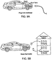
- An automotive or other power system including a flow cell in which the stack that provides power is readily isolated from the storage vessels holding the cathode slurry and anode slurry (alternatively called "fuel") is described.
- a method of use is also provided, in which the "fuel" tanks are removable and are separately charged in a charging station, and the charged fuel, plus tanks, are placed back in the vehicle or other power system, allowing fast refueling.
- the technology also provides a charging system in which discharged fuel is charged.
- the charged fuel can be placed into storage tanks at the power source or returned to the vehicle. In some embodiments, the charged fuel in the storage tanks can be used at a later date.
- the charged fuel can be transported or stored for use in a different place or time.
- a power system includes a redox flow battery in which at least one of the positive electrode or anode slurries of the fuel is semi-solid or is a condensed liquid reactant, and in which at least one of the electrode-active materials is transported to and from an assembly at which the electrochemical reaction occurs, producing electrical energy.
- semi-solid it is meant that the material is a mixture of liquid phase and solid phases, such a mixture also being known as a slurry, particle suspension, colloidal suspension, emulsion, or micelle.
- the solid constituents of the semi-solid comprise at least one material that undergoes reaction or alloying or intercalation with the working ions of the battery to generate or store electrical energy.
- the electroactive material of the redox couple can remain in the semi-solid in both of its oxidative states without going into solution. Therefore, the solubility of the electroactive material no longer limits its concentration in the electroactive zone, resulting in a large increase of the effective concentration of the electroactive materials in the flow cell. As a result, the energy density of the cell using semi-solid redox composition is greatly increased.
- the liquid supporting the electroactive component can be aqueous or non-aqueous.
- the redox flow battery comprises a non-aqueous cell, including but not limited to an alkali ion rechargeable cell wherein the working ion is an alkali ion.
- Solvents typically used as electrolyte solvents may be used as the liquid in the semi-solid cathode or anode slurries.
- condensed liquid or condensed ion-storing liquid refers to a liquid that is not merely a solvent as it is in the case of an aqueous flow cell catholyte or anolyte, but rather that the liquid is itself redox-active.
- the liquid form can also be diluted by or mixed with another, non-redox-active liquid that is a diluent or solvent, including mixing with such a diluents to form a lower-melting liquid phase, emulsion or micelles including the ion-storing liquid.
- the working ion of the redox couple can remain in the condensed liquid phase in both of its oxidative states without going into solution. Therefore, the solubility of the electroactive material no longer limits its concentration in the electroactive zone, resulting in a large increase of the effective concentration of the electroactive materials in the flow cell. As a result, the energy density of the cell using condensed liquid redox composition is greatly increased.
- the redox flow battery is a lithium battery of primary or rechargeable type.
- at least one of the energy storing electrodes comprises a condensed liquid of a redox active material, including but not limited to lithium metal, gallium and indium alloys, molten transition metal chlorides, thionyl chloride, and the like. Further information on redox batteries may be found in co-pending provisional patent application number 61/060972, filed June 12, 2008 , entitled "High Energy Density Redox Flow Battery", which is incorporated herein in its entirety by reference.
- a conventional flow battery anolyte and catholyte and the ion-storing solid or liquid phases as exemplified herein is the molar concentration or molarity of redox species in the storage compound.
- conventional anolytes or catholytes that have redox species dissolved in aqueous solution may be limited in molarity to typically 2M to 8M concentration. Highly acidic solutions may be necessary to reach the higher end of this concentration range.
- any flowable semi-solid or condensed liquid ion-storing redox composition as described herein may have, when taken in moles per liter or molarity, at least 10M concentration of redox species, preferably at least 12M, still preferably at least 15M, and still preferably at least 20M, because the solubility of the electroactive materials no longer limits it concentration in the flow cell.
- the electrochemically active material can be an ion storage material or any other compound or ion complex that is capable of undergoing Faradaic reaction in order to store energy.
- the electroactive material can also be a multiphase material including the above-described redox-active solid or liquid phase mixed with a non-redox-active phase, including solid-liquid suspensions, or liquid-liquid multiphase mixtures, including micelles or emulsions having a liquid ion-storage material intimately mixed with a supporting liquid phase.
- the "stack" or electricity generating portion of the battery is reversibly coupled to vessels or containers holding the cathode slurry and anode slurry.
- the power system is illustrated in Fig. 1 .
- the power system includes an energy stack 100 that contain electrodes and chambers for flowing the anode slurry and cathode slurry.
- the anode slurry is pumped from vessel 120 by a pump (not shown) through an entry conduit 130 into the energy stack.
- the conduit 130 and vessel 120 and are fitted with quick disconnect fittings 140 that permit the release and connection of the vessel to the power system.
- the cathode slurry is pumped from a vessel 150 by pump (not shown) through an entry conduit 160 into the energy stack.
- the conduit 160 and vessel 150 are fitted with quick disconnect fittings 170 that permit the release and connection of the vessel to the power system.
- the consumed or 'spent' anode slurry and cathode slurry is removed from the stack using exit conduits 135 and 165, respectively.
- Exit conduits are also fitted with quick release fittings (not shown).
- Energy stack 100 may optionally have a quick disconnect fitting 155, 155 as well.
- the vessel or fuel container is removable from the system and may be easily replace or refilled when the anode slurry or cathode slurry is consumed or 'spent.'
- redox composition fluid is circulated constantly through the flow cell while being slightly charged and discharged with each pass.
- the conduit can be rigid or flexible and can be prepared from conventional materials capable of withstanding a range of temperature conditions and which are chemically stable in contact with the slurries.
- Exemplary materials include metals such as copper or brass or stainless steel, elastomers, polyolefins, and fluoropolymers such as TeflonTM.
- the fittings may be any conventional fitting used to connect and disconnect tubing or piping, selected to provide a hermetic seal and to be chemically stable in contact with the slurries of the invention.
- Exemplary fittings include those commonly referred to as quick disconnect hose fittings or hydraulic quick disconnect couplers.
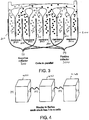
- Fig. 2 is a cross-sectional view of an interior portion of the energy stack illustrating the intake manifolds for the anode slurry and cathode slurry.
- the energy stack includes a plurality of cells, each containing a positive electrode 200 in contact with cathode slurry 210, a negative electrode 220 in contact with anode slurry 230, and ionically conductive membrane 240 separating the anode slurry from the cathode slurry.
- the electrodes are in contact with the respective anode and cathode slurries on both faces of the electrode.
- the cells can be efficiently arranged in facing arrangement as is known in the art for solid batteries.
- Each cell includes an anode slurry inlet 250 to permit inflow of anode slurry and a cathode slurry inlet 260 to permit flow of cathode slurry.
- the anode slurry inlets may be part of a manifold having a single inlet source 270 from anode slurry vessel 120.
- the cathode slurry inlets may be part of a manifold having a single inlet source 280 from anode slurry vessel 120.
- the flow divide can occur inside or outside of the energy stack.
- the energy stack can be arranged to provide a plurality of electrochemical cells that are electrically connected in parallel or in series to provide a power system having a desired set of properties.
- Battery packs get their desired operating voltage by connecting several cells in series. For example, electrochemical cells that are connected in series will result in a cell in which the overall voltage of the system is the sum of the individual cell voltages. If higher capacity and current handling is required, the cells are connected in parallel. Some packs have a combination of serial and parallel connections.
- Fig. 3 is a cross-sectional view of an electrical stack in which the cells of the stack are electrically connected in parallel.
- the stack including a plurality of positive current collectors 200 are joined at a positive terminal 300.
- the plurality of negative current collectors 220 are joined at negative terminal 310.
- Individual energy stacks can be further connected, either in series or in parallel to provide the desired battery performance.
- Fig. 4 is a perspective view of a plurality of energy stacks 400, 410, 420 that are joined in series.
- the individual cells of the energy stack may be joined in series or parallel.
- the power system can include any number of individual energy stacks to provide the desired voltage.
- each of the energy stacks has a manifold to distribute the input cathode slurry and anode slurry to the individual cells as shown in Figs. 2 and 3 . If a number of stacks are present, there would be a main cathode slurry flow line that goes to the cathode input on each of the stacks. A main anode slurry flow line can be used similarly with the anode slurry.
- the flow cell stack is intergrated into an energy system.
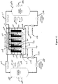
- Fig. 10 illustrates a multi-redox flow cell stack device 1001.
- the multi-cell stack device includes end electrodes 1019 (anode) and 1020 (cathode) at the end of the device, as well as one or more bipolar electrodes such as 1021. Between the electrodes, the multi-cell stack device also includes anode slurry compartments such as 1015 and cathode slurry compartments such as 1016. The two compartments are separated by ionically conductive membranes such as 1022. This arrangement is repeated to include multi-cell design in the device.
- Bipolar electrode 1021 includes a cathode (cathode current collector) 1025 which faces the cathode slurry cell compartment 1016 and an anode (anode current collector) 1026 which faces the anode slurry cell compartment 1027.
- a heat sink or a insulator layer 1028 is disposed in between cathode 1025 and anode 1026.
- the heat sink comprises a coolant.
- the electrode arrangement described here in Fig. 10 is different from that in Fig. 2 and represent an alternative design of the multi-redox flow cell stack, i.e ., individual cells instead of face to face cells.
- the current collector is electronically conductive and should be electrochemically inactive under the operation conditions of the cell.
- Typical current collectors for lithium redox flow cells include copper, aluminum, or titanium for the negative current collector and aluminum for the positive current collector, in the form of sheets or mesh, or any configuration for which the current collector may be distributed in the electrolyte and permit fluid flow. Selection of current collector materials is well-known to those skilled in the art.
- aluminum is used as the current collector for positive electrode.
- copper is used as the current collector for negative electrode.
- the membrane can be any conventional membrane that is capable of ion transport.
- the membrane is a liquid-impermeable membrane that permits the transport of ions therethrough, namely a solid or gel ionic conductor.
- the membrane is a porous polymer membrane infused with a liquid electrolyte that allows for the shuttling of ions between the anode and cathode electroactive materials, while preventing the transfer of electrons.
- the membrane is a microporous membrane that prevents particles forming the positive and negative electrode flowable compositions from crossing the membrane.
- Exemplary membrane materials include polyethyleneoxide (PEO) polymer in which a lithium salt is complexed to provide lithium conductivity, or NafionTM membranes which are proton conductors.
- PEO polyethyleneoxide
- NafionTM membranes which are proton conductors.
- PEO based electrolytes can be used as the membrane, which is pinhole-free and a solid ionic conductor, optionally stabilized with other membranes such as glass fiber separators as supporting layers.
- PEO can also be used as a slurry stabilizer, dispersant, etc. in the positive or negative flowable redox compositions.
- PEO is stable in contact with typical alkyl carbonate-based electrolytes. This can be especially useful in phosphate-based cell chemistries with cell potential at the positive electrode that is less than about 3.6 V with respect to Li metal.
- the operating temperature of the redox cell can be elevated as necessary to improve the ionic conductivity of the membrane.
- a bipolar electrode includes a cathode and an anode separated by a coolant region for introducing a coolant through the bipolar electrode.
- coolants include ethylene glycol and water.
- the multi-cell stack device is connected to an anode slurry storage tank 1002 which stores the anode slurry.
- a positive displacement pump 1004 is used to pump anode slurry through a flow meter 1006 and a check valve 1007 into a manifold 1013, which delivers the anode slurry into multiple anode slurry cell compartments such as 1015.
- the discharged anode slurry is removed through manifold 1017, flow valve 1011 and back into the tank 1002.
- a positive displacement pump 1005 is used to pump cathode slurry from storage tank 1003, through a flow meter 1023 and a check valve 1024 into a manifold 1014, which delivers the cathode slurry into cathode slurry cell compartments such as 1016.
- the discharged cathode slurry is removed through manifold 1018, flow valve 1012 and back into the tank 1003.
- a positive displacement pump causes a fluid to move by trapping a fixed amount of it then forcing (displacing) that trapped volume through the pump.
- Positive displacement pump 1004 or 1005 can minimize the loss of the fluid through the pump, and any positive displacement pump known in the art can be used.
- other means of fluid transport can be used.
- Flow meter 1006 or 1023 measures and controls the amount of anode slurry or cathode slurry that is pumped into the cell compartments. Any type of flow meter known in the art can be used. Non-limiting examples of flow meters include electric flow meters, turbine flow meters, mass flow meters and positive displacement flow meters.
- Check valves 1007 and 1024 are used to prevent the back flow of the fluids. Any check valves known in the art can be used.
- Non-limiting examples of flow valves 1011 and 1012 include any mechanical or electrical valves. Flow valves are further discussed in greater details in Fig. 13 .
- a level meter 1008 can be connected to the storage tank 1002 or 1003 to monitor the levels of the cathode slurry or anode slurry inside the tank.
- Temperature monitors 1010 and pressure monitors 1009 can also be connected to the storage tank to monitor the temperature and pressure within the tank.
- Fig. 11 illustrates a multi-redox flow cell stack device 1101 where the flow directions of the cathode slurry and anode slurry are reversible.
- the reversible nature of the pumps allows the discharge and recharge of the electroactive slurry to take place in situ.
- the multi-cell stack device also includes anode slurry compartments such as 1115 and cathode slurry compartments such as 1116. The two compartments are separated by ionically conductive membranes such as 1122.
- As least one of the anode slurry and cathode slurry in the anode slurry and cathode slurry compartments contain semi-solid or condensed liquid as described above.
- the multi-redox flow cell 1101 is connected to anode slurry storage tank 1102 and cathode slurry storage tank 1104.
- Anode slurry storage tank 1102 further contains a bladder 1103.
- the charged anode slurry in storage tank 1102 is pumped, in the direction as indicated by arrow 1108, by using a reversible flow pump 1106.
- the anode slurry passes flow meter 1117, flow valve 1118 and into the manifold 1110.
- the manifold 1110 delivers charged anode slurry into anode slurry cell compartments such as 1115.
- the discharged anode slurry can be removed through manifold 1115 and pumped through valve 1119 into bladder 1103 for storage.
- the flow direction within the reversible flow pump 1106 is reversed and the discharged anode slurry in bladder 1103 can be pumped, in the direction as indicated by arrow 1109, through valve 1119 and into manifold 1115, which delivers the discharged anode slurry into the anode slurry compartments such as 1115.
- a voltage is then applied to the device and the discharged anode slurry can be recharged.
- cathode slurry storage tank 1104 further contains a bladder 1105.
- the charged cathode slurry in storage tank 1104 is pumped, in the direction as indicated by arrow 1111, by using a reversible flow pump 1107.
- the cathode slurry passes flow meter 1120, flow valve 1121 and into the manifold 1113.
- the manifold 1113 delivers charged cathode slurry into cathode slurry cell compartments such as 1116.
- the discharged cathode slurry can be removed through manifold 1114 and pumped through valve 1123 into bladder 1105 for storage.
- the flow direction within the reversible flow pump 1107 is reversed and the discharged cathode slurry in bladder 1105 can be pumped, in the direction as indicated by arrow 1112, through valve 1123 and into manifold 1114, which delivers the discharged cathode slurry into the cathode slurry compartments such as 1116.
- a voltage is then applied to the device and the discharged cathode slurry can be recharged.
- the flow valves and flow meters are as described above.
- the semi-solid or condensed liquid anode slurry or cathode slurry as described above are electrically conductive materials.
- shunt current may occur to bypass one or more cell compartments and/or bipolar electrodes in the device.
- the current can go through the cathode slurry or anode slurry in the manifold to bypass one or more cell compartments and/or bipolar electrodes in the device.
- non-conductive valves can be introduced at the inlet or outlet position of the manifold to reduce or prevent the shunt current.
- Fig. 12 illustrates a multi-cell semi-solid flow cell stack design and various types of valves that can be incorporated into the design.
- Fig. 12A illustrates a multi-cell semi-solid flow cell stack design 1201 which includes end-electrodes 1209 and 1211, bipolar electrodes such as 1210 and 1212, membranes such as 1213 which separates anode slurry cell compartment 1215 and cathode slurry cell compartment 1214.
- Valves such as 1202 are positioned at one of the inlet positions of the manifold 1204, which delivers cathode slurry into the cathode slurry cell compartment 1214.
- Valves such as 1216 are positioned at one of the inlet positions of the manifold 1203, which delivers anode slurry into the anode slurry cell compartment 1215. Valves such as 1202 and 1216 are non-conductive thus can prevent the shunt current through the manifold.
- such valves are pulsating valves and open for only a short period of time to allow the anode slurry or cathode slurry to pass through quickly without resulting in any shunt current.
- additional valves are positioned at the outlet position 1207 of manifold 1206 and at the outlet position 1208 of manifold 1205.
- valves described above are any mechanical or electrical operated valves.
- the valve is a solenoid valve.
- suitable non-conductive valves are illustrated in Figs. 12B-12E.
- Fig. 12B illustrates the open and close forms of a valve including a ball-like switch. The valve is activated by pressure differentiation of the two side of the valves.
- Fig. 12C illustrates the open and close forms of a valve including a coin-like switch. The valve is activated by pressure differentiation of the two side of the valves.
- Fig. 12D illustrates the open and close forms of a valve including a flapper-like switch.
- the valve can be activated by a spring mechanism to allow the fluid flow.
- the valve can also by activated by a double-spring mechanism to reverse the direct of the flow.
- a double-spring mechanism can be controlled mechanically or electrically.
- Different types of heart mechanical valves can also used.
- Fig. 12E illustrates the open and close forms of a valve including a membrane switch.
- the membrane is made out of "shape memory membrane material" which changes its shape when activated.
- the membrane-switch can be activated electrically.
- Other examples include tissue valves which can be electrically activated.
- Other valves known in the art are also contemplated.
- Fig. 13 illustrates a multi-port injection system for semi-solid flow multi-cell stack.
- a multi port injection system can precisely control the amount of fluid being delivered to each "plenum" or cell compartment. If a group of cells need more fluid to increase the voltage a multi-port injection will be able to accomplish this without affecting the other compartments. Increase fluid flow accuracy and controls.
- the multiflow cell design includes injectors such as 1301 (in manifold 1302) and 1305 (in manifold 1307). During operation, the anode slurry is introduced into manifold 1302 and injected into plenum region 1303 by injectors such as 1301.
- the plenum region 1303 is pressurized so that the anode slurry, once injected into anode slurry cell compartment 1308, will not back-flow into the manifold 1303.
- the cathode slurry is introduced into manifold 1307 and injected into plenum region 1306 by injectors such as 1305.
- the plenum region 1306 is pressurized so that the cathode slurry, once injected into cathode slurry cell compartment 1309, will not back-flow into the manifold 1307. Because the flow direction is controlled, the shunt current through the manifold is also minimized. Such configuration can reduce or minimize the shunt current between fluids in different "plenums”.
- Pressure transducers such as 1304 are included in the manifold to monitor and control the pressure within the manifold.
- the inside of the manifold used to deliver cathode and anode slurries and, optionally, coolant, is coated with non-conductive materials to minimize shunt current across the fluids.
- the manifold itself is made of an electrically insulating material such as a polymer or ceramic.
- Fig. 14 illustrates a plan view of one of bipolar plates of a multi-redox flow cell stack design assembled by stacked plates such as described above with reference to Fig. 10 .
- the plate includes an active region 1401 which comprises a cathode current collector or an anode current collector.
- Region 1402 includes opening 1404 which is used as part of the manifold to deliver anode slurry into the anode slurry cell compartment.
- Region 1402 also includes opening 1405 which is used as part of the manifold to deliver cathode slurry into the cathode slurry cell compartment.
- Region 1402 also optionally includes opening 1406 which is used as part of a manifold to deliver coolant into the bipolar electrode.
- Region 1403 includes opening 1407 which is used as part of the manifold to remove cathode slurry from the cathode slurry cell compartment.
- Region 1403 includes opening 1409 which is used as part of the manifold to remove discharged anode slurry from the anode slurry cell compartment.
- Region 1403 also optionally includes opening 1408 which is used as part of a manifold to remove coolant from the bipolar electrode.
- a channel (not shown) disposed between the two electrodes of the bipolar electrode is used to hold the coolant and is connected with openings 1406 and 1408.
- the plates which comprise cell compartments and membranes between the electrodes also comprises similar openings as those described in Fig. 14 .
- the bipolar plates such as 1410 and end electrode plates as described are aligned together, stacked with cell compartments and membranes in between and form a semi-solid flow multi-cell stack 1501 as illustrated in Fig. 15 , with all the corresponding openings of different plates properly aligned.
- Manifold 1502 is formed by stacking the plates together and aligning similar openings on each plate accordingly.
- Manifold 1502 is used to introduce anode slurry into the anode slurry cell compartment.
- manifold 1503 is formed to introduce cathode slurry into the cathode slurry cell compartment.
- Manifolds 1505 and 1504 are also formed to remove anode slurrys and cathode slurry from the cell compartments, respectively.
- channels or manifolds such as 1506 and 1507 are also formed, which are used for introducing and removing the coolant from the device, respectively.
- the inside of the openings 1405, 1406, 1407, 1408, 1409, and 1410 can be coated with non-conductive materials.
- the manifolds formed for anode slurry, cathode slurry, and optionally coolant all have non-conductive inside thus minimized unwanted, parasitic shunt currents to flow through anode slurry, cathode slurry, and the coolant. Any non-conductive coating known in the art can be used.
- Non-limiting examples of the non-conductive coatings include non-conductive polymers such as epoxies, polyamide-imides, polyether imides, polyphenols, fluro-elastomers, polyesters, phenoxy-phenolics, epoxidephenolics, acrylics and urethanes.
- non-conductive polymers such as epoxies, polyamide-imides, polyether imides, polyphenols, fluro-elastomers, polyesters, phenoxy-phenolics, epoxidephenolics, acrylics and urethanes.
- a feature of the power system using redox flow cells as the energy and power source is that the anode slurry and cathode slurry can be introduced into the energy stack at a high state of charge, that is, the electroactive components of the system is fully charged.
- anode slurry and cathode slurry flow e.g., are pumped, into the energy stack 500 from fuel storage vessels 510 and 520, respectively, and into individual cells and flow past current collectors.
- the redox-active ions or ion complexes undergo oxidation or reduction when they are in close proximity to or in contact with a conductive electrode or current collector that typically does not itself undergo redox activity.
- the redox-active materials discharge, e . g ., the state of charge diminishes.
- the state of charge is reduced and the anode slurry and cathode slurry are 'spent.'
- the spent suspensions are then collected in spent fuel storage vessels 530 and 540, respectively.
- the fuels cells 510 and 520 are empty, and spent fuel tank 530 and 540 are full, they can be swapped out and replaced with fresh containers of fuel and empty spent fuel containers. In this manner, the device being powered by the power system, e . g ., an electric or hybrid electric motor vehicle, is refueled.
- Fig. 6A is a perspective view of tank 600 that can be used for delivering either anode slurry or cathode slurry to the energy stack, and receiving the spent fuel.
- Tank 600 includes an upper chamber 610 and a lower chamber 620.
- the upper chamber is in flow communication with the intake manifold of the cathode slurry or anode slurry through conduit 615. Once the fuel has been consumed in the energy stack, it exits the stack and returns to the lower chamber 620 through conduit 625.
- Tank 600 includes a moveable inner wall or membrane 628 that can move up and down in the tank interior to increase or decrease the size of the two interior chamber to adjust for the constantly changing relative volume of liquid in the two chambers.
- the membrane is selected to be flexible over the temperature range of use, sufficiently strong to withstand the forces and pressures encountered in use, chemically stable in contact with the components of the cathode and anode slurries, and impermeable or permeable to the electrolyte.
- a single tank 700 is used for the out flow and uptake of both anode slurry and cathode slurry.
- tank 700 includes upper chambers 710 and 720 for housing fresh anode slurry and cathode slurry, respectively.
- the tank also includes lower chambers 750 and 760 for receiving spend anode slurry and cathode slurry, respectively.
- the tank can include a moveable membrane or wall 730, 740 that moves in response to the relative change in volume of fresh and spent fuels. The two membranes can move together or independently.
- the fresh anode slurry is fed into the energy stack from conduit 765; similarly, the fresh cathode slurry is fed into the energy stack from conduit 775.
- the spent anode slurry and cathode slurry return to tank 700 through conduits 785 and 795, respectively.
- Wall 715 separates the anode slurry from the cathode slurry and may be stationary or moveable.
- the particular type of tank used may depend on the intended use of the power system.
- the four tank system described in Fig. 5 can be used and may be most appropriate for providing large volume of fuel, which permits longer distances before refueling.
- the one tank, four compartment tank described in Fig. 6B is compact and occupies less spaced. It can easily be swapped out in a single step.
- the tank, with its additional elements and moving parts, is more expensive to make and use.
- a premium grade of fuel may include a cathode slurry or anode slurry or both that provides higher power, or longer operational time and therefore driving range, or both, in the same volume of "fuel.”
- a cathode slurry or anode slurry or both that provides higher power, or longer operational time and therefore driving range, or both, in the same volume of "fuel.”
- the differences in power and range provided by properly engineered slurries can be very dramatic - the power may be 10% or 20% or 50% or even 100% greater for one slurry than another, as may be the driving range, for the same size "gas tank.”
- one use model of the invention is to provide, within the same volume or size of "fuel tank” or total system size including stacks, widely varying performance capabilities.
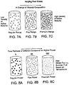
- Fig. 7 illustrates varying fuel grade in tanks of the same size.
- the fuel can range from a low grade fuel having a low fuel mileage range (7A) to a medium “plus” grade fuel having a medium mileage range (7B) and even can include a "premium” grade of higher grade fuel that provides the best mileage range (7C).
- the grades of fuel can be adjusted by changing a number of variables in the cathode and anode slurries.
- the number or density of electrode particles in a slurry can be adjusted in order to adjust the charge capacity per unit volume of slurry, with higher particle density having greater charge capacity and longer driving range.
- Figs. 7A-7C illustrates fuel tanks of the same size having an increased density of particles with increasing fuel grade.
- a lithium iron phosphate or lithium cobalt oxide based fuel system can be prepared at particle densities that provide a total volume percentage of the active material in the slurry ranging from about 20 volume % to about 70 volume %.
- the additional particle density is typically accompanied by a change in viscosity or rheology of the slurries, which may necessitate a change in the pumping procedure such as pumping rate or intermittency of pumping.
- the range of regular, plus and premium ranges of fuel can be obtained by using different electroactive materials having different charge capacities.
- the power of the fuel is modified and the consumer may select between regular, plus power and premium power batteries.
- Fig. 8 fuel grades based on power is illustrated.
- the power system may be able to operate using anode and cathode slurries having different power, e.g ., the delivery of larger or smaller amounts of energy per unit time.
- the power of the anode or cathode slurries can be varied by modifying the particle size of the electroactive particles in the slurry. A smaller particle size would have a greater surface area and therefore a greater amount of working surface available per unit mass, as well as a smaller dimension through which the solid-state transport of lithium takes place, thereby providing higher discharge power.
- a lithium iron phosphate based cathode may be prepared in average crystallite sizes of 30 nm, 50 nm, and 100 nm, and a corresponding graphite based anode slurries may contain particle sizes of 1 micrometer, 5 micrometers, and 20 micrometers.
- the crystallite size is not necessarily the same as the particle size since particles may consist of agglomerates or aggregates of individual crystallites.
- the electroactive materials of the slurries may be varied to provide different power capabilities in the different fuel systems.
- Another use model is to provide to the consumer various tank sizes. Unlike a conventional vehicle in which the size of the fuel tank is determined at time of manufacturing, in the present invention the ability to readily exchange slurry tanks for refueling, one can provide tanks of different sizes for different needs. For example, a consumer may purchase a larger tank of fuel, and give up some storage space in a car, when taking a longer trip.
- the ability to conveniently exchange the fuel tanks provides several options for recharging, as illustrated in Fig. 9A-9B .
- the spent cathode and anode slurries typically contain electroactive materials developed for standard secondary batteries and may be recharged under conditions that are similar to those developed for those materials in standard secondary battery formats.
- a consumer may recharge the spent anode and cathode slurries while the fuels are hooked up to the power system, by plugging the power system into an alternative power source, e.g ., a wall outlet, and initiating a recharging cycle in the power system.
- the two slurries are pumped in the reverse direction while charging, and are stored, presumably in the original tanks.
- the user when traveling or short on time, can swap fuel tanks at a recharging station.
- the user returns spent fuels at a recharging station and receives fresh slurries.
- the charging station can replace the fuel tanks (like the model used for refilling propane tanks) or simply empty and refill the existing tanks.
- the ability to swap fuel tanks would provide flexibility in the type of fuel and fuel capacity available to the user, as discussed above.
- the user can change grade, power or tank capacity from refill to refill.
- the cathode/anode ratio is fixed at the time of manufacturing and cannot be changed if the operating conditions of the battery require it, such as if at high power one of the electrodes has slower kinetics and therefore more of that electrode would be advantageous.
- the properties of the power system can be varied or altered as needed.
- the flow rates of the cathode and anode slurries can be different.
- a lithium phosphate-based cathode suspension used with a graphite anode suspension may be rate-limited by the lithium uptake capability of the anode because too fast a charge rate may result in Li plating at the anode.
- the plating can be avoided.
- the voltage of the cell will remain higher because anode slurry will exit the stack at a higher state of charge.
- the flow rates of the cathode and anode slurries, or Cathode/Anode ratio in-situ can be varied to accommodate any degradation of the electrode slurries that occurred during use. Rather than simply replacing or discarding the slurry, it may be used at a different flow rate to improve the performance of the cell, for example, keeping performance within specifications, even if lower than with new slurries. That is, the operating life of the cell can be improved and extended by increasing the flow rate of one or both slurries, or by changing the Cathode/Anode ratio up or down.
- the cell voltage is maintained at a relatively higher level by increasing the flow rate of both slurries, so that each is operating at a high state of charge during periods of higher power demand.
- the energy available in the slurries may not be fully utilized during such operational periods, but the power can be improved.
- this can be accomplished by increasing the flow rate of just one electrode slurry as well to keep that slurry at higher rate.
- the stack includes monitoring devices that provide the power system or a power management system with information concerning the condition of the power system. This information may be used, in real time or prior to use, to select the optimal operating conditions of the power system. By way of example, the temperature, flow rates, and relative amounts of the cathode and anode slurries can be controlled.
- Another use model is to evaluate, replenish, or recondition the fuel slurries at a service provider or manufacturer at one or more times in the life of the fuel slurries.
- the electrodes cannot be reconditioned during the battery's life.
- each slurry can be reconditioned to restore or extend the battery life.
- the fuel may first be tested at the service provider to evaluate its condition when it is returned for charging or service.
- it can be reconditioned in several ways. For example, residual water may be sequestered from the suspension. Additional salt to improve ion conductivity may be added. Solvents or electrolyte additives may be added.
- Additional solid phases including active materials used for ion storage, or conductive additives, may be added.
- the solid phases may be separated from the liquid electrolyte, for example by filtering centrifugation, or the addition of coagulation aids to cause the solid phases to be less well suspended.
- the solids or solid-enriched suspension and the separated liquid electrolyte may be individually treated, or even replaced.
- any combination of replenishing or reconditioning steps may be performed as well. Doing so can decrease the expense of the system over its useful life by selectively replacing or reconditioning specific failed components, improve lifetime or performance as new additives or components are discovered, or aid in the recycling of the materials.
- Another use model is to replace the power "stack" of the flow battery separately from the fuel tanks or other components. Unlike a conventional battery, the ability to replace only certain components as they degrade, or as upgrades are desired, provides economic advantages to both the user and the service provider or manufacturer. Thus, in one or more embodiments, the energy stack is removed from the power system and is replaced or repaired.
- the power system can include an electrical energy storage device and power source that is simultaneously a conventional rechargeable battery and a flow cell in one integrated device. It is applicable to various battery chemistries, including aqueous batteries such as nickel metal hydride types, and nonaqueous batteries including lithium rechargeable batteries, sodium rechargeable batteries, or batteries based on other alkali or alkaline earth or non-alkaline working ions. Considering one embodiment based on lithium ion chemistry, the basic construction of such a cell has a separator, on one side of which is a lithium battery positive electrode or a negative electrode, or both, as in a conventional rechargeable lithium battery.
- a separator on one side of which is a lithium battery positive electrode or a negative electrode, or both, as in a conventional rechargeable lithium battery.
- the electrodes comprise cathode or anode active material, and may comprise a coating of the active material on a metallic current collector, or may be a stand-alone electrode layer such as a densified or sintered layer comprising the active material, optionally with other constituents such as polymer binders or carbonaceous conductive additives or metallic additives or binders.
- These ion-storage electrodes will be referred to as the stationary electrodes.
- one or both of the stationary electrodes is permeable to a flow cell cathode slurry or anode slurry, so that during operation of the device, it is possible to charge or discharge only the active materials on the stationary electrode, only the flow cell cathode slurry or anode slurry, or both.
- One embodiment of the invention uses a cathode slurry or anode slurry that is a semi-solid fluid, or suspension, or slurry, as described in previous filings.
- one or both of the stationary electrodes are immediately adjacent to the separator layer, including being coated on the separator.
- this permits relatively rapid charge and discharge of the battery using the working ions stored in the stationary electrodes.
- the ions stored in the cathode slurry and anode slurry are also available to the device and can be charged and discharged, although this may occur at a different kinetic rate than the stationary electrodes.
- Such a design allows the single device to provide a high power charge or discharge for a relatively shorter period of time, while also having the high energy provided by the flow cell aspects of the design.
- the stationary electrodes are situated between the separator and the flow cell reactants, and optionally may also serve as the current collectors for one or more of the flow cell reactants.
- Another advantage of such a design is that the stationary electrodes can provide mechanical support to the separator layer or reduce abrasion or wear of the separator when the cathode slurry and anode slurry are in the form of a semi-solid fluid or suspension or slurry.
- one or more of the flow cell reactants flow in between the separator layer and the stationary electrodes.
- the flow cell cathode slurry or anode slurry can add or remove working ions from the stationary electrodes.
- the stationary negative electrode may be relatively depleted, and the stationary positive electrode relatively saturated, with the working ions.
- the flow cell cathode slurry and anode slurry can exchange ions with the stationary electrodes to bring the entire cell back towards a charged state, from which it is able to provide another high power discharge pulse.
- this design can provide high pulse power capability, as is required for electric vehicles, while also providing the high storage energy characteristics of a flow cell.
Landscapes
- Engineering & Computer Science (AREA)
- Life Sciences & Earth Sciences (AREA)
- Sustainable Development (AREA)
- Sustainable Energy (AREA)
- Chemical & Material Sciences (AREA)
- Chemical Kinetics & Catalysis (AREA)
- Electrochemistry (AREA)
- General Chemical & Material Sciences (AREA)
- Manufacturing & Machinery (AREA)
- Power Engineering (AREA)
- Transportation (AREA)
- Mechanical Engineering (AREA)
- Dispersion Chemistry (AREA)
- Fuel Cell (AREA)
Applications Claiming Priority (3)
| Application Number | Priority Date | Filing Date | Title |
|---|---|---|---|
| US16695809P | 2009-04-06 | 2009-04-06 | |
| US23585909P | 2009-08-21 | 2009-08-21 | |
| EP10714130.1A EP2417664B1 (fr) | 2009-04-06 | 2010-04-06 | Système d'alimentation utilisant une batterie à flux redox |
Related Parent Applications (2)
| Application Number | Title | Priority Date | Filing Date |
|---|---|---|---|
| EP10714130.1A Division-Into EP2417664B1 (fr) | 2009-04-06 | 2010-04-06 | Système d'alimentation utilisant une batterie à flux redox |
| EP10714130.1A Division EP2417664B1 (fr) | 2009-04-06 | 2010-04-06 | Système d'alimentation utilisant une batterie à flux redox |
Publications (1)
| Publication Number | Publication Date |
|---|---|
| EP3240078A1 true EP3240078A1 (fr) | 2017-11-01 |
Family
ID=42313286
Family Applications (2)
| Application Number | Title | Priority Date | Filing Date |
|---|---|---|---|
| EP17157342.1A Pending EP3240078A1 (fr) | 2009-04-06 | 2010-04-06 | Système de carburant |
| EP10714130.1A Active EP2417664B1 (fr) | 2009-04-06 | 2010-04-06 | Système d'alimentation utilisant une batterie à flux redox |
Family Applications After (1)
| Application Number | Title | Priority Date | Filing Date |
|---|---|---|---|
| EP10714130.1A Active EP2417664B1 (fr) | 2009-04-06 | 2010-04-06 | Système d'alimentation utilisant une batterie à flux redox |
Country Status (7)
| Country | Link |
|---|---|
| US (4) | US8778552B2 (fr) |
| EP (2) | EP3240078A1 (fr) |
| JP (2) | JP5882888B2 (fr) |
| KR (1) | KR102046773B1 (fr) |
| CN (2) | CN105280937B (fr) |
| CA (1) | CA2757969C (fr) |
| WO (1) | WO2010118060A1 (fr) |
Cited By (1)
| Publication number | Priority date | Publication date | Assignee | Title |
|---|---|---|---|---|
| EP3933989A4 (fr) * | 2019-02-27 | 2022-05-04 | Sumitomo Electric Industries, Ltd. | Batterie à flux rédox |
Families Citing this family (128)
| Publication number | Priority date | Publication date | Assignee | Title |
|---|---|---|---|---|
| US8277964B2 (en) | 2004-01-15 | 2012-10-02 | Jd Holding Inc. | System and method for optimizing efficiency and power output from a vanadium redox battery energy storage system |
| US8722226B2 (en) * | 2008-06-12 | 2014-05-13 | 24M Technologies, Inc. | High energy density redox flow device |
| US9786944B2 (en) | 2008-06-12 | 2017-10-10 | Massachusetts Institute Of Technology | High energy density redox flow device |
| US11909077B2 (en) | 2008-06-12 | 2024-02-20 | Massachusetts Institute Of Technology | High energy density redox flow device |
| US7820321B2 (en) | 2008-07-07 | 2010-10-26 | Enervault Corporation | Redox flow battery system for distributed energy storage |
| US8785023B2 (en) | 2008-07-07 | 2014-07-22 | Enervault Corparation | Cascade redox flow battery systems |
| CN105280937B (zh) | 2009-04-06 | 2018-04-10 | 24M技术公司 | 采用氧化还原液流电池的燃料系统 |
| JP5417441B2 (ja) * | 2009-06-09 | 2014-02-12 | シャープ株式会社 | レドックスフロー電池 |
| US8399138B2 (en) * | 2009-10-14 | 2013-03-19 | GM Global Technology Operations LLC | Liquid rechargeable lithium ion battery |
| JP5944830B2 (ja) * | 2009-12-16 | 2016-07-05 | マサチューセッツ インスティテュート オブ テクノロジー | 高エネルギー密度レドックスフロー装置 |
| US10651492B2 (en) | 2010-06-22 | 2020-05-12 | Vrb Energy Inc. | Integrated system for electrochemical energy storage system |
| US20120164499A1 (en) * | 2010-08-18 | 2012-06-28 | Massachusetts Institute Of Technology | Stationary, fluid redox electrode |
| US8202641B2 (en) * | 2010-09-08 | 2012-06-19 | Primus Power Corporation | Metal electrode assembly for flow batteries |
| US20120308856A1 (en) * | 2010-12-08 | 2012-12-06 | Enervault Corporation | Shunt current resistors for flow battery systems |
| EP2652825A4 (fr) * | 2010-12-16 | 2015-03-11 | 24M Technologies Inc | Procédé et conception de cellules d'écoulement empilées |
| US8709629B2 (en) | 2010-12-22 | 2014-04-29 | Jd Holding Inc. | Systems and methods for redox flow battery scalable modular reactant storage |
| JP2014513857A (ja) * | 2010-12-23 | 2014-06-05 | 24エム・テクノロジーズ・インコーポレイテッド | 半固体充填電池及び製造方法 |
| US9257710B2 (en) * | 2011-01-13 | 2016-02-09 | Imergy Power Systems, Inc. | Flow battery start-up and recovery management |
| US8980484B2 (en) | 2011-03-29 | 2015-03-17 | Enervault Corporation | Monitoring electrolyte concentrations in redox flow battery systems |
| US8916281B2 (en) | 2011-03-29 | 2014-12-23 | Enervault Corporation | Rebalancing electrolytes in redox flow battery systems |
| KR101824032B1 (ko) * | 2011-06-01 | 2018-01-31 | 케이스 웨스턴 리저브 유니버시티 | 철 기반 플로우 배터리 |
| US20120328927A1 (en) * | 2011-06-24 | 2012-12-27 | GM Global Technology Operations LLC | Electrochemical devices and rechargeable lithium ion batteries |
| CN102315473A (zh) * | 2011-06-28 | 2012-01-11 | 北京好风光储能技术有限公司 | 一种锂离子液流电池 |
| US20130045399A1 (en) * | 2011-08-16 | 2013-02-21 | Primus Power Corporation | Flow Battery with Reactant Separation |
| CN102403519B (zh) * | 2011-08-19 | 2015-02-04 | 中国电力科学研究院 | 一种液流电池的集成系统 |
| CN104040764B (zh) * | 2011-09-07 | 2018-02-27 | 24M技术公司 | 具有多孔集流体的半固体电极电池及其制造方法 |
| US9774044B2 (en) * | 2011-09-21 | 2017-09-26 | United Technologies Corporation | Flow battery stack with an integrated heat exchanger |
| EP2761689B1 (fr) * | 2011-09-28 | 2017-11-08 | United Technologies Corporation | Batterie à circulation comprenant stockage biphasé |
| US10141594B2 (en) | 2011-10-07 | 2018-11-27 | Vrb Energy Inc. | Systems and methods for assembling redox flow battery reactor cells |
| CN103094599B (zh) * | 2011-10-28 | 2016-03-16 | 北京好风光储能技术有限公司 | 一种锂离子液流电池及其反应器和电极盒 |
| US9853454B2 (en) | 2011-12-20 | 2017-12-26 | Jd Holding Inc. | Vanadium redox battery energy storage system |
| CN103219537B (zh) * | 2012-01-19 | 2015-05-13 | 北京好风光储能技术有限公司 | 一种锂离子液流反应管,锂离子液流电池及其反应器 |
| US9966625B2 (en) | 2012-02-28 | 2018-05-08 | Uchicago Argonne, Llc | Organic non-aqueous cation-based redox flow batteries |
| US9300000B2 (en) | 2012-02-28 | 2016-03-29 | Uchicago Argonne, Llc | Organic non-aqueous cation-based redox flow batteries |
| US9130217B2 (en) * | 2012-04-06 | 2015-09-08 | Primus Power Corporation | Fluidic architecture for metal-halogen flow battery |
| US20150093606A1 (en) * | 2012-05-10 | 2015-04-02 | Beijing Hawaga Power Storage Technology Company Ltd. | Pump-free lithium ion liquid flow battery, battery reactor and preparation method of electrode suspension solution |
| US9401501B2 (en) | 2012-05-18 | 2016-07-26 | 24M Technologies, Inc. | Electrochemical cells and methods of manufacturing the same |
| US9484569B2 (en) | 2012-06-13 | 2016-11-01 | 24M Technologies, Inc. | Electrochemical slurry compositions and methods for preparing the same |
| WO2013188636A1 (fr) * | 2012-06-15 | 2013-12-19 | University Of Delaware | Modèle de batteries à flux redox comportant plusieurs membranes et plusieurs électrolytes |
| JP5740357B2 (ja) * | 2012-06-29 | 2015-06-24 | 株式会社日立製作所 | 大容量蓄電装置 |
| CN102760902B (zh) * | 2012-07-26 | 2014-09-03 | 杭州电子科技大学 | 一种独立式全液态燃料电池的燃料液压输送装置 |
| CN104756286A (zh) * | 2012-08-23 | 2015-07-01 | 伊奈沃特公司 | 氧化还原液流电池中的电解质的压力平衡 |
| US9362583B2 (en) | 2012-12-13 | 2016-06-07 | 24M Technologies, Inc. | Semi-solid electrodes having high rate capability |
| US8993159B2 (en) | 2012-12-13 | 2015-03-31 | 24M Technologies, Inc. | Semi-solid electrodes having high rate capability |
| FR3003038B1 (fr) * | 2013-03-06 | 2016-08-19 | Ifp Energies Now | Procede de determination de la capacite residuelle d'une batterie |
| AU2014225947B2 (en) * | 2013-03-08 | 2017-10-19 | Primus Power Corporation | Reservoir for multiphase electrolyte flow control |
| US20140272653A1 (en) * | 2013-03-14 | 2014-09-18 | Robert Bosch Gmbh | Flow Battery System and Method of SOC Determination |
| WO2014150210A1 (fr) | 2013-03-15 | 2014-09-25 | 24M Technologies, Inc. | Batterie asymétrique comprenant une cathode semi-solide et une anode haute densité |
| DE102013005864A1 (de) * | 2013-04-08 | 2014-10-09 | Murrplastik Verwaltung- und Beteiligungs-GmbH | Redox-Flow-Zelle |
| WO2014200482A1 (fr) * | 2013-06-13 | 2014-12-18 | United Technologies Corporation | Batterie à flux à passage de collecteurs qui varie en section transversale |
| JP6536835B2 (ja) * | 2013-07-10 | 2019-07-03 | レッドフロー アール アンド ディー プロプライエタリー リミテッドRedFlow R&D Pty Ltd | 流動電解液電池、および流動電解液電池を制御する方法 |
| WO2015009990A2 (fr) | 2013-07-19 | 2015-01-22 | 24M Technologies, Inc. | Électrodes semi-solides avec un additif polymère |
| JP5916819B2 (ja) * | 2013-08-26 | 2016-05-11 | 一般社団法人新エネルギー支援機構 | 電力エネルギーの輸送システム |
| US9590228B1 (en) | 2013-11-01 | 2017-03-07 | HRL Laboratroies, LLC | Three-dimensional micro-lattice battery structures with convective flow of electrolytes |
| WO2015080492A1 (fr) * | 2013-11-27 | 2015-06-04 | 국립대학법인 울산과학기술대학교 산학협력단 | Batterie secondaire et système de batterie secondaire |
| KR101520394B1 (ko) * | 2013-12-19 | 2015-05-14 | 한국에너지기술연구원 | 스택형 플로우 에너지 저장 장치 및 그 용도 |
| GB201405855D0 (en) * | 2014-04-01 | 2014-05-14 | Imp Innovations Ltd | Hybrid electrochemical energy device |
| US10230128B2 (en) | 2014-04-09 | 2019-03-12 | 24M Technologies, Inc. | Damage tolerant batteries |
| CN104064797B (zh) * | 2014-06-14 | 2017-01-04 | 中国科学院电工研究所 | 一种锂离子液流电池系统 |
| JP5850094B2 (ja) * | 2014-06-24 | 2016-02-03 | トヨタ自動車株式会社 | レドックス型燃料電池 |
| JP2017531983A (ja) | 2014-10-13 | 2017-10-26 | 24エム・テクノロジーズ・インコーポレイテッド24M Technologies, Inc. | 直列電池充電及び形成用のシステム及び方法 |
| WO2016073438A1 (fr) | 2014-11-03 | 2016-05-12 | 24M Technologies, Inc. | Prélithiation de matériaux d'électrode dans une électrode semi-solide |
| EP4300666A3 (fr) | 2014-11-05 | 2024-02-21 | 24m Technologies, Inc. | Cellules électrochimiques à électrodes semi-solides et leurs procédés de fabrication |
| EP3218947B1 (fr) | 2014-11-10 | 2018-12-19 | LANXESS Solutions US Inc. | Dispositif de stockage d'énergie comprenant un séparateur en polyuréthane |
| US10186716B2 (en) | 2014-11-10 | 2019-01-22 | Lanxess Solutions Us Inc. | Non-aqueous flow cell comprising a polyurethane separator |
| KR101676126B1 (ko) * | 2014-12-16 | 2016-11-15 | 오씨아이 주식회사 | 레독스 플로우 전지의 펌프 속도 제어 방법 및 장치 |
| JP5916912B1 (ja) * | 2015-03-13 | 2016-05-11 | 一般社団法人新エネルギー支援機構 | 電力充電供給システム |
| EP3082186B1 (fr) | 2015-04-14 | 2019-07-24 | Lanxess Solutions US Inc. | Cellule d'écoulement non aqueux comprenant un séparateur de polyuréthane |
| US10115970B2 (en) | 2015-04-14 | 2018-10-30 | 24M Technologies, Inc. | Semi-solid electrodes with porous current collectors and methods of manufacture |
| EP3295501A4 (fr) | 2015-05-15 | 2019-01-23 | COMPOSITE MATERIALS TECHNOLOGY, Inc. | Batteries rechargeables à grande capacité améliorées |
| US10593952B2 (en) | 2015-05-19 | 2020-03-17 | 24M Technologies Inc. | Mechanical systems and methods for providing edge support and protection in semi-solid electrodes |
| US10181587B2 (en) | 2015-06-18 | 2019-01-15 | 24M Technologies, Inc. | Single pouch battery cells and methods of manufacture |
| CN113594485A (zh) | 2015-06-19 | 2021-11-02 | 24M技术公司 | 电化学电池修复方法 |
| TWI540782B (zh) | 2015-06-30 | 2016-07-01 | 財團法人工業技術研究院 | 電解質組合物、及包含其之能量儲存裝置 |
| FR3039323B1 (fr) * | 2015-07-21 | 2017-08-11 | Ifp Energies Now | Systeme et procede de stockage et de restitution d'energie electrochimique a flux de particules redox |
| US11784341B2 (en) * | 2015-12-08 | 2023-10-10 | The Chinese University Of Hong Kong | High-energy density and low-cost flow electrochemical devices with moving rechargeable anode and cathode belts |
| WO2017124098A1 (fr) | 2016-01-15 | 2017-07-20 | 24M Technologies, Inc. | Systèmes et procédés de mélange par infusion d'une électrode à base de suspension concentrée |
| CN105539188B (zh) * | 2016-01-25 | 2018-01-02 | 杭州海韵环保工程有限公司 | 一种液流电动车系统 |
| US10290891B2 (en) | 2016-01-29 | 2019-05-14 | Primus Power Corporation | Metal-halogen flow battery bipolar electrode assembly, system, and method |
| KR101976344B1 (ko) | 2016-03-10 | 2019-05-07 | 쓰리엠 이노베이티브 프로퍼티즈 컴파니 | 전극 용액과 그로부터의 전기화학 셀 및 배터리 |
| US10069161B2 (en) | 2016-03-17 | 2018-09-04 | Saudi Arabian Oil Company | In-situ gravitational separation of electrolyte solutions in flow redox battery systems |
| US20190051922A1 (en) * | 2016-03-17 | 2019-02-14 | 3M Innovative Properties Company | Membrane assemblies, electrode assemblies, membrane-electrode assemblies and electrochemical cells and liquid flow batteries therefrom |
| US10215402B2 (en) | 2016-03-31 | 2019-02-26 | King Fahd University Of Petroleum And Minerals | Gas-assisted liguid fuel oxygen reactor |
| JP6191893B1 (ja) * | 2016-04-26 | 2017-09-06 | 行政院原子能委員会核能研究所 | フロー電池の岐路電流抑制装置及びその方法 |
| CN106099179A (zh) * | 2016-06-15 | 2016-11-09 | 上海电气集团股份有限公司 | 一种流体电池正、负极悬浮电解液及其制备方法 |
| JP6924389B2 (ja) * | 2016-07-01 | 2021-08-25 | 住友電気工業株式会社 | レドックスフロー電池、電気量の測定システム、及び電気量の測定方法 |
| WO2018004466A1 (fr) * | 2016-07-01 | 2018-01-04 | Temasek Polytechnic | Module de plaque bipolaire pour batterie à flux redox et empilement de batterie à flux redox l'utilisant |
| CN109562950B (zh) | 2016-09-01 | 2020-05-19 | 复合材料技术公司 | 用于LIB阳极的阀金属基底上的纳米级/纳米结构Si涂层 |
| US10707531B1 (en) | 2016-09-27 | 2020-07-07 | New Dominion Enterprises Inc. | All-inorganic solvents for electrolytes |
| FR3057709B1 (fr) * | 2016-10-19 | 2018-11-23 | IFP Energies Nouvelles | Batterie a flux redox comportant un systeme de reduction des courants de derivation |
| FR3057997B1 (fr) * | 2016-10-25 | 2018-12-07 | Kemiwatt | Accumulateur electrochimique en flux avec allongement du chemin de fluide |
| CN106595082A (zh) * | 2016-11-28 | 2017-04-26 | 北京有色金属研究总院 | 一种太阳能光热发电用金属氢化物储热装置 |
| US10374239B2 (en) | 2016-12-29 | 2019-08-06 | Uchicago Argonne, Llc | Aqueous pyridinium cation-based redox flow batteries |
| EP3577704A4 (fr) | 2017-02-01 | 2021-03-10 | 24m Technologies, Inc. | Systèmes et procédés pour améliorer des caractéristiques de sécurité dans des cellules électrochimiques |
| KR101855290B1 (ko) | 2017-03-02 | 2018-05-04 | 스탠다드에너지(주) | 레독스 흐름전지 |
| WO2018183828A1 (fr) | 2017-03-31 | 2018-10-04 | 24M Technologies, Inc. | Protection contre la surcharge de batteries utilisant des dispositifs d'interruption de courant |
| WO2018187817A1 (fr) * | 2017-04-07 | 2018-10-11 | Applied Physical Electronics, L.C. | Pile à combustible à micro-particules d'ions lithium |
| US10283824B2 (en) * | 2017-04-21 | 2019-05-07 | Ford Global Technologies, Llc | Thermal exchange assembly for vehicle battery |
| CN110582878B (zh) * | 2017-04-28 | 2023-10-31 | Ess技术有限公司 | 使用加压多室罐的集成水循环系统 |
| DE102017110521A1 (de) * | 2017-05-15 | 2018-11-15 | Cfd Consultants Gmbh | System mit einer Redox-Flow-Batterie |
| US10553890B2 (en) | 2017-06-23 | 2020-02-04 | Uchicago Argonne, Llc | Aqueous redox flow batteries |
| WO2019027901A1 (fr) | 2017-07-31 | 2019-02-07 | 24M Technologies, Inc. | Dispositifs d'interruption de courant utilisant des matériaux à mémoire de forme |
| US10424805B2 (en) | 2017-08-15 | 2019-09-24 | Uchicago Argonne, Llc | Benzothiophene-based redox molecules for flow battery |
| US10854869B2 (en) | 2017-08-17 | 2020-12-01 | 24M Technologies, Inc. | Short-circuit protection of battery cells using fuses |
| US10734672B2 (en) | 2018-01-08 | 2020-08-04 | 24M Technologies, Inc. | Electrochemical cells including selectively permeable membranes, systems and methods of manufacturing the same |
| CN110120542B (zh) * | 2018-02-07 | 2020-12-25 | 北京好风光储能技术有限公司 | 一种高能量密度锂浆料电池及其工作方法 |
| EP3804006A1 (fr) | 2018-05-24 | 2021-04-14 | 24M Technologies, Inc. | Électrodes à gradient, à haute densité d'énergie, et procédés pour leur fabrication |
| US11094487B2 (en) | 2018-06-25 | 2021-08-17 | 24M Technologies, Inc. | Current interrupt device based on thermal activation of frangible glass bulb |
| US11139467B2 (en) | 2018-07-09 | 2021-10-05 | 24M Technologies, Inc. | Continuous and semi-continuous methods of semi-solid electrode and battery manufacturing |
| US11056698B2 (en) | 2018-08-02 | 2021-07-06 | Raytheon Technologies Corporation | Redox flow battery with electrolyte balancing and compatibility enabling features |
| CN111326770A (zh) * | 2018-12-14 | 2020-06-23 | 株式会社电装 | 电解液站和电力管理系统 |
| KR102170731B1 (ko) * | 2018-12-19 | 2020-10-27 | 한국기초과학지원연구원 | 인시츄 광학 및 전기화학 분석 방법 및 이를 위한 전지 셀 측정 모듈 |
| CN112018370B (zh) * | 2019-05-28 | 2022-04-15 | 中国科学院宁波材料技术与工程研究所 | 金属单质的制备方法 |
| US11631920B2 (en) | 2019-06-27 | 2023-04-18 | 24M Technologies, Inc. | Dual electrolyte electrochemical cells, systems, and methods of manufacturing the same |
| US20220247015A1 (en) * | 2019-07-12 | 2022-08-04 | Ampcera Inc. | Interally heatable battery, internally heatable battery system, internally heatable battery method, and electric vehicle comprising the same |
| US11271237B2 (en) | 2019-07-29 | 2022-03-08 | Uchicago Argonne, Llc | Organic redox molecules for flow batteries |
| CN115244729A (zh) | 2020-01-21 | 2022-10-25 | 24M技术公司 | 用于形成具有高活性固体加载的半固体电极和包括其的电化学电池的装置和方法 |
| US11742525B2 (en) | 2020-02-07 | 2023-08-29 | 24M Technologies, Inc. | Divided energy electrochemical cell systems and methods of producing the same |
| GB2592359A (en) * | 2020-02-18 | 2021-09-01 | Connect4Engineering Ltd | Electrode with lattice structure |
| EP4107802A1 (fr) | 2020-02-21 | 2022-12-28 | 24M Technologies, Inc. | Cellules électrochimiques dotées d'un matériau d'électrode couplé directement à un film et leurs procédés de fabrication |
| IT202000016600A1 (it) * | 2020-07-09 | 2022-01-09 | Univ Degli Studi Padova | Metodo di gestione dello stato di carica per batterie a flusso redox e batteria a flusso redox |
| WO2022043542A1 (fr) * | 2020-08-31 | 2022-03-03 | Fundación Imdea Energía | Pile à électrode recyclable |
| US11271226B1 (en) | 2020-12-11 | 2022-03-08 | Raytheon Technologies Corporation | Redox flow battery with improved efficiency |
| IT202100002096A1 (it) * | 2021-02-02 | 2022-08-02 | Graf Ind S P A | Batteria ricaricabile e relativa stazione di ricarica |
| WO2023126858A1 (fr) * | 2021-12-29 | 2023-07-06 | Enlighten Innovations Inc. | Système de batterie à métal fondu avec des modes de production de métal et de batterie à flux |
| WO2023220576A1 (fr) * | 2022-05-09 | 2023-11-16 | Lockheed Martin Energy, Llc | Distribution uniforme de courants de type shunt dans une batterie à circulation |
| US11984564B1 (en) | 2022-12-16 | 2024-05-14 | 24M Technologies, Inc. | Systems and methods for minimizing and preventing dendrite formation in electrochemical cells |
| CN115863532B (zh) * | 2022-12-22 | 2024-03-29 | 烯晶碳能电子科技无锡有限公司 | 一种双极性电极的制造工艺 |
Citations (8)
| Publication number | Priority date | Publication date | Assignee | Title |
|---|---|---|---|---|
| US4126733A (en) | 1976-05-10 | 1978-11-21 | Sorapec Societe de Recherches et d'Application Electronchimiques | Electrochemical generator comprising an electrode in the form of a suspension |
| US5368952A (en) | 1991-06-12 | 1994-11-29 | Stork Screens B.V. | Metal suspension half-cell for an accumulator, method for operating such a half-cell and metal suspension accumulator comprising such a half-cell |
| EP0330290B1 (fr) | 1988-02-26 | 1996-05-15 | Stork Screens B.V. | Matière d'électrode pour utilisation dans une demi-cellule d'accumulateur contenant une suspension, demi-cellule d'accumulateur ayant une électrode d'une telle manière et accumulateur comportant une telle demi-cellule d'accumulateur |
| US6097208A (en) | 1996-10-02 | 2000-08-01 | Fujitsu Limited | Signal-transfer system and semiconductor device for high-speed data transfer |
| GB2374722A (en) * | 2001-04-20 | 2002-10-23 | Innogy Technology Ventures Ltd | Regenerative fuel cell with ph control |
| US20030022059A1 (en) * | 2000-12-06 | 2003-01-30 | Takefumi Ito | Pressurre fluctuation prevention tank structure, electrolyte circulation type secondary battery, and redox flow type secondary battery |
| US20030211377A1 (en) * | 2002-05-07 | 2003-11-13 | Holmes Charles M. | Fuel-cell based power source having internal series redundancy |
| WO2008148148A1 (fr) * | 2007-06-07 | 2008-12-11 | V-Fuel Pty Ltd | Systèmes efficaces de stockage d'énergie à l'aide de batteries redox au vanadium pour le marché de l'électricité, la diminution de la consommation de combustibles fossiles et des dépenses en énergie électrique pour les consommateurs |
Family Cites Families (119)
| Publication number | Priority date | Publication date | Assignee | Title |
|---|---|---|---|---|
| US3255046A (en) | 1961-02-16 | 1966-06-07 | Union Carbide Corp | Means for converting high energy radiation to electrical energy |
| US3551207A (en) | 1961-03-30 | 1970-12-29 | Exxon Research Engineering Co | Fuel cell |
| US3360401A (en) | 1965-09-29 | 1967-12-26 | Standard Oil Co | Process for converting chemical energy into electrical energy |
| CH468727A (de) * | 1967-02-07 | 1969-02-15 | Battelle Memorial Inst Interna | Elektrischer Akkumulator |
| US3540933A (en) | 1967-07-11 | 1970-11-17 | Jan Boeke | Redox fuel cell |
| US3540934A (en) | 1967-07-11 | 1970-11-17 | Jan Boeke | Multiple cell redox battery |
| US3996064A (en) | 1975-08-22 | 1976-12-07 | The United States Of America As Represented By The Administrator Of The National Aeronautics And Space Administration | Electrically rechargeable REDOX flow cell |
| US4814240A (en) * | 1976-07-12 | 1989-03-21 | Solomon Zaromb | Metal-consuming power generation methods |
| US4018971A (en) | 1976-07-20 | 1977-04-19 | The United States Of America As Represented By The Administrator Of The National Aeronautics And Space Administration | Gels as battery separators for soluble electrode cells |
| US4159366A (en) | 1978-06-09 | 1979-06-26 | The United States Of America As Represented By The Administrator Of The National Aeronautics And Space Administration | Electrochemical cell for rebalancing redox flow system |
| US4192910A (en) | 1978-11-29 | 1980-03-11 | Nasa | Catalyst surfaces for the chromous/chromic redox couple |
| JPS5834912B2 (ja) | 1979-10-19 | 1983-07-29 | 工業技術院長 | 燃料電池 |
| US4335191A (en) | 1980-07-28 | 1982-06-15 | Tadiran Israel Electronics Industries Ltd. | Lithium cells |
| IL61085A (en) | 1980-09-19 | 1983-07-31 | Univ Ramot | Nonaqueous sulfur cell |
| US4375501A (en) | 1980-10-17 | 1983-03-01 | Gte Laboratories Incorporated | Electrochemical cell |
| US4318969A (en) | 1980-11-21 | 1982-03-09 | Gte Laboratories Incorporated | Electrochemical cell |
| FR2495842A1 (fr) | 1980-12-05 | 1982-06-11 | Comp Generale Electricite | Generateur electrochimique a electrode negative liquide |
| US4352864A (en) | 1981-04-06 | 1982-10-05 | Universal Fuel Systems, Inc. | Metal/acid ion permeable membrane fuel cell |
| US4443522A (en) | 1981-04-06 | 1984-04-17 | Struthers Ralph C | Metal/acid ion permeable membrane fuel cell |
| US4382116A (en) | 1981-05-22 | 1983-05-03 | The United States Of America As Represented By The Administrator Of The National Aeronautics And Space Administration | Zirconium carbide as an electrocatalyst for the chromous/chromic REDOX couple |
| US4370392A (en) | 1981-06-08 | 1983-01-25 | The University Of Akron | Chrome-halogen energy storage device and system |
| US4784924A (en) | 1981-06-08 | 1988-11-15 | University Of Akron | Metal-halogen energy storage device and system |
| IL63337A (en) | 1981-07-16 | 1984-03-30 | Univ Ramot | Electrochemical reserve cell |
| IL63336A (en) | 1981-07-16 | 1984-03-30 | Univ Ramot | Electrochemical cell |
| US4485154A (en) | 1981-09-08 | 1984-11-27 | Institute Of Gas Technology | Electrically rechargeable anionically active reduction-oxidation electrical storage-supply system |
| JPS5913153A (ja) * | 1982-07-12 | 1984-01-23 | Nissan Motor Co Ltd | 気筒数可変エンジン搭載車の自動変速機制御装置 |
| EP0108002A1 (fr) | 1982-10-21 | 1984-05-09 | Transports Recherches Etudes Groupement D'interet Economique (T.R.E.G.I.E.) | Dispositif de fonctionnement d'un générateur électrochimique à électrode négative de zinc |
| CA1244078A (fr) | 1984-06-06 | 1988-11-01 | Takafumi Hashimoto | Batterie secondaire a metal-halogene |
| JPS61201270U (fr) * | 1985-06-06 | 1986-12-17 | ||
| US4576878A (en) | 1985-06-25 | 1986-03-18 | The United States Of America As Represented By The Administrator Of The National Aeronautics And Space Administration | Method and apparatus for rebalancing a redox flow cell system |
| IL77786A (en) | 1986-02-04 | 1990-02-09 | Univ Ramot | Electrochemical cell |
| JPS62229665A (ja) * | 1986-03-29 | 1987-10-08 | Sumitomo Electric Ind Ltd | 電解液流通型2次電池 |
| JPS63281362A (ja) * | 1987-05-12 | 1988-11-17 | Nkk Corp | レドックスフロ−型電池 |
| JPS63285875A (ja) * | 1987-05-18 | 1988-11-22 | Chubu Electric Power Co Inc | レドックスフロ−型電池 |
| JP2649700B2 (ja) | 1988-06-03 | 1997-09-03 | 関西電力株式会社 | レドックスフロー電池の電解液再生装置 |
| US5079104A (en) | 1991-03-18 | 1992-01-07 | International Fuel Cells | Integrated fuel cell stack shunt current prevention arrangement |
| US5308718A (en) | 1993-01-15 | 1994-05-03 | Globe-Union Inc. | End block constructions for batteries |
| US5599638A (en) | 1993-10-12 | 1997-02-04 | California Institute Of Technology | Aqueous liquid feed organic fuel cell using solid polymer electrolyte membrane |
| US5441820A (en) | 1993-10-26 | 1995-08-15 | Regents, University Of California | Electrically recharged battery employing a packed/spouted bed metal particle electrode |
| DE69432428D1 (de) | 1993-11-17 | 2003-05-08 | Pinnacle Vrb Ltd | Stabilisierte elektrolytlösungen, verfahren und deren herstellung und redoxzellen und batterien, die diese lösungen enthalten |
| US5849427A (en) | 1993-12-02 | 1998-12-15 | Lawrence Berkeley Laboratory | Hydraulically refueled battery employing a packed bed metal particle electrode |
| US5558961A (en) | 1994-06-13 | 1996-09-24 | Regents, University Of California | Secondary cell with orthorhombic alkali metal/manganese oxide phase active cathode material |
| US5656390A (en) | 1995-02-16 | 1997-08-12 | Kashima-Kita Electric Power Corporation | Redox battery |
| JPH08259767A (ja) * | 1995-03-20 | 1996-10-08 | Sumitomo Electric Ind Ltd | 導電性プラスチック板およびそれを用いた電池セル |
| CA2220075C (fr) | 1995-05-03 | 2008-07-08 | Unisearch Limited | Electrolyte au vanadium a haute densite d'energie, ses procedes de preparation, et cellules et batteries redox tout-vanadium contenant ledit electrolyte |
| US5610802A (en) | 1995-05-23 | 1997-03-11 | Zb B Technologies, Inc. | Compact energy storage system |
| US5650239A (en) | 1995-06-07 | 1997-07-22 | Zbb Technologies, Inc. | Method of electrode reconditioning |
| US5591538A (en) | 1995-07-07 | 1997-01-07 | Zbb Technologies, Inc. | Zinc-bromine battery with non-flowing electrolyte |
| US5600534A (en) | 1995-10-12 | 1997-02-04 | Zbb Technologies, Inc. | Capacitor having non-conductive plastic frames |
| US5601943A (en) | 1995-10-26 | 1997-02-11 | Zbb Technologies, Inc. | Module for an aqueous battery system |
| US5804329A (en) | 1995-12-28 | 1998-09-08 | National Patent Development Corporation | Electroconversion cell |
| JPH09223513A (ja) | 1996-02-19 | 1997-08-26 | Kashimakita Kyodo Hatsuden Kk | 液循環式電池 |
| US5837397A (en) | 1996-11-08 | 1998-11-17 | Gould Electronics Inc. | Laminar (flat or paper-type) lithium-ion battery with slurry anodes and slurry cathodes |
| US5792576A (en) | 1996-11-08 | 1998-08-11 | Gould Electronics Inc. | Limited rechargeable lithium battery based on a cathode slurry |
| US6482374B1 (en) | 1999-06-16 | 2002-11-19 | Nanogram Corporation | Methods for producing lithium metal oxide particles |
| US5869200A (en) | 1997-08-12 | 1999-02-09 | Sunsave, Inc. | Magnetic slurry fueled battery system |
| US5912088A (en) | 1997-10-28 | 1999-06-15 | Plug Power, L.L.C. | Gradient isolator for flow field of fuel cell assembly |
| EP1066656B1 (fr) | 1998-02-24 | 2011-04-06 | Tel-Aviv University Future Technology Development L.P. | Matrices conductrice d'ions et leurs utilisations |
| IL124007A (en) | 1998-04-08 | 2001-08-26 | Univ Ramot | Long cycle-life alkali metal battery |
| AU767055B2 (en) | 1998-05-06 | 2003-10-30 | Zbb Technologies Inc. | Spill and leak containment system for zinc-bromine battery |
| KR20010071430A (ko) | 1998-06-09 | 2001-07-28 | 추후보정 | 에너지 저장 시스템 |
| US6500571B2 (en) | 1998-08-19 | 2002-12-31 | Powerzyme, Inc. | Enzymatic fuel cell |
| GB2346006B (en) | 1999-01-20 | 2001-01-31 | Nat Power Plc | Method of carrying out electrochemical reactions |
| US6277520B1 (en) | 1999-03-19 | 2001-08-21 | Ntk Powerdex, Inc. | Thin lithium battery with slurry cathode |
| JP3051401B1 (ja) * | 1999-03-29 | 2000-06-12 | 川崎重工業株式会社 | 電 池 |
| ID30457A (id) | 1999-03-29 | 2001-12-06 | Kawasaki Heavy Ind Ltd | Baterai dan peralatan atau piranti yang mempunyai baterai sebagai bagian strukturnya, dan metode pembangkitan daya yang didistribusikan secara lokal dan piranti pembangkit daya untuk itu |
| PT1143546E (pt) | 1999-09-27 | 2009-11-27 | Sumitomo Electric Industries | Bateria de fluxo redox |
| US6447943B1 (en) | 2000-01-18 | 2002-09-10 | Ramot University Authority For Applied Research & Industrial Development Ltd. | Fuel cell with proton conducting membrane with a pore size less than 30 nm |
| EP1249053B1 (fr) | 2000-01-18 | 2010-06-16 | Tel-Aviv University Future Technology Development L.P. | Pile a combustible a membrane conductrice de protons |
| US6296958B1 (en) | 2000-03-08 | 2001-10-02 | Metallic Power, Inc. | Refuelable electrochemical power source capable of being maintained in a substantially constant full condition and method of using the same |
| GB2362752B (en) * | 2000-03-24 | 2002-06-05 | Innogy Ltd | Method of operating a fuel cell |
| JP3979774B2 (ja) * | 2000-09-25 | 2007-09-19 | クロリンエンジニアズ株式会社 | レドックスフロー電池 |
| US6455187B1 (en) | 2000-10-03 | 2002-09-24 | Premium Power Acquisition Corporation | Recombinator for the re-acidification of an electrolyte stream in a flowing electrolyte zinc-bromine battery |
| US20050175890A1 (en) | 2000-10-31 | 2005-08-11 | Kazuo Tsutsumi | Battery |
| EP1244168A1 (fr) * | 2001-03-20 | 2002-09-25 | Francois Sugnaux | Electrode à réseau mésoporeux pour batterie |
| JP2002289233A (ja) * | 2001-03-23 | 2002-10-04 | Hitachi Zosen Corp | レドックスフロー電池タンク |
| CA2447681A1 (fr) | 2001-05-18 | 2002-11-28 | Unisearch Limited | Electrolyte pour batterie redox au vanadium |
| JP3897544B2 (ja) | 2001-06-07 | 2007-03-28 | 住友電気工業株式会社 | レドックスフロー電池用電解液およびレドックスフロー電池 |
| CN1209219C (zh) | 2001-06-26 | 2005-07-06 | 艾铭南 | 制备银原子的设备 |
| RU2295804C2 (ru) | 2001-07-18 | 2007-03-20 | Тель-Авив Юниверсити Фьючер Текнолоджи Дивелопмент Л.П. | Топливный элемент с протонопроводящей мембраной и с усовершенствованным регулированием расхода воды и топлива |
| US7270911B2 (en) | 2001-08-10 | 2007-09-18 | Plurion Limited | Load leveling battery and methods therefor |
| US7252905B2 (en) | 2001-08-10 | 2007-08-07 | Plurion Limited | Lanthanide batteries |
| US6986966B2 (en) | 2001-08-10 | 2006-01-17 | Plurion Systems, Inc. | Battery with bifunctional electrolyte |
| US7625663B2 (en) | 2001-08-10 | 2009-12-01 | Plurion Limited Company | Cerium batteries |
| US7560189B2 (en) | 2001-08-10 | 2009-07-14 | Plurion Limited | Mixed electrolyte battery |
| US7297437B2 (en) | 2001-08-10 | 2007-11-20 | Plurion Limited | Battery with gelled electrolyte |
| US20060063065A1 (en) | 2001-08-10 | 2006-03-23 | Clarke Robert L | Battery with bifunctional electrolyte |
| AUPR722101A0 (en) | 2001-08-24 | 2001-09-13 | Skyllas-Kazacos, Maria | Vanadium chloride/polyhalide redox flow battery |
| CA2471455C (fr) | 2001-12-21 | 2014-08-05 | Massachusetts Institute Of Technology | Electrode conductrice de stockage de lithium |
| JP4028732B2 (ja) * | 2002-01-21 | 2007-12-26 | 株式会社水素エネルギー研究所 | 発電方法 |
| US7033696B2 (en) | 2002-02-12 | 2006-04-25 | Plurion Systems, Inc. | Electric devices with improved bipolar electrode |
| US7214443B2 (en) | 2002-02-12 | 2007-05-08 | Plurion Limited | Secondary battery with autolytic dendrites |
| JP4155745B2 (ja) * | 2002-02-27 | 2008-09-24 | 住友電気工業株式会社 | レドックスフロー電池の運転方法 |
| AUPS192102A0 (en) | 2002-04-23 | 2002-05-30 | Unisearch Limited | Vanadium bromide redox flow battery |
| JP4185311B2 (ja) * | 2002-05-10 | 2008-11-26 | 新興化学工業株式会社 | バナジウムレドックスフロー電池電解液用固形組成物 |
| US20060032046A1 (en) | 2002-10-17 | 2006-02-16 | Menachem Nathan | Thin-film cathode for 3-dimensional microbattery and method for preparing such cathode |
| CA2517690C (fr) * | 2003-03-14 | 2012-06-19 | Michael Kazacos | Nouvelle batterie a flux redox d'halogenure de vanadium |
| AU2003901763A0 (en) | 2003-04-14 | 2003-05-01 | Michael Kazacos | Novel bromide redox flow cells and batteries |
| US6979512B2 (en) | 2003-03-19 | 2005-12-27 | Phillips Edward D | Colloidal battery |
| US7521149B2 (en) | 2004-08-11 | 2009-04-21 | Medeiros Maria G | High efficiency semi-fuel cell incorporating an ion exchange membrane |
| GB2424511B (en) * | 2005-03-22 | 2007-01-24 | Intellikraft Ltd | Lithium sulphide battery and method of producing the same |
| CN100438190C (zh) * | 2005-03-29 | 2008-11-26 | 攀钢集团攀枝花钢铁研究院 | 全钒离子液流电池电解液及其制备方法 |
| CN101185185B (zh) * | 2005-05-31 | 2010-04-07 | 松下电器产业株式会社 | 二次电池和使用了该二次电池的电源系统、以及电源系统的使用方法 |
| DK1905117T3 (da) | 2005-06-20 | 2019-08-19 | Newsouth Innovations Pty Ltd | Forbedrede perfluorerede membraner og forbedrede elektrolytter til redoxceller og batterier |
| US7828619B1 (en) * | 2005-08-05 | 2010-11-09 | Mytitek, Inc. | Method for preparing a nanostructured composite electrode through electrophoretic deposition and a product prepared thereby |
| US8133629B2 (en) * | 2007-03-21 | 2012-03-13 | SOCIéTé BIC | Fluidic distribution system and related methods |
| WO2008128341A1 (fr) | 2007-04-19 | 2008-10-30 | National Research Council Of Canada | Piles à combustible redox à combustible direct |
| CN101192678A (zh) * | 2007-05-29 | 2008-06-04 | 北京普能世纪科技有限公司 | 一种干式可充钒电池的制造技术 |
| DE102007034700A1 (de) * | 2007-07-16 | 2009-01-22 | Rennebeck, Klaus, Dr. | Redox-Batterie |
| JP5211775B2 (ja) * | 2008-03-14 | 2013-06-12 | 株式会社豊田中央研究所 | スラリー利用型二次電池 |
| US8097364B2 (en) * | 2008-03-31 | 2012-01-17 | Integrated Resource Recovery, Inc | Electroactive material for charge transport |
| CA2720600C (fr) | 2008-04-07 | 2017-09-12 | Jay Whitacre | Dispositif de stockage d'energie secondaire electrochimique sous forme d'electrolyte aqueux base sur des ions de sodium |
| US8722226B2 (en) * | 2008-06-12 | 2014-05-13 | 24M Technologies, Inc. | High energy density redox flow device |
| US9786944B2 (en) * | 2008-06-12 | 2017-10-10 | Massachusetts Institute Of Technology | High energy density redox flow device |
| US20100047671A1 (en) * | 2008-06-12 | 2010-02-25 | Massachusetts Institute Of Technology | High energy density redox flow device |
| CN105280937B (zh) | 2009-04-06 | 2018-04-10 | 24M技术公司 | 采用氧化还原液流电池的燃料系统 |
| JP5944830B2 (ja) | 2009-12-16 | 2016-07-05 | マサチューセッツ インスティテュート オブ テクノロジー | 高エネルギー密度レドックスフロー装置 |
| US20110274948A1 (en) | 2010-04-09 | 2011-11-10 | Massachusetts Institute Of Technology | Energy transfer using electrochemically isolated fluids |
| US20120164499A1 (en) | 2010-08-18 | 2012-06-28 | Massachusetts Institute Of Technology | Stationary, fluid redox electrode |
-
2010
- 2010-04-06 CN CN201510583811.3A patent/CN105280937B/zh not_active Expired - Fee Related
- 2010-04-06 EP EP17157342.1A patent/EP3240078A1/fr active Pending
- 2010-04-06 KR KR1020117026293A patent/KR102046773B1/ko active IP Right Grant
- 2010-04-06 CN CN201080025219.7A patent/CN102576893B/zh active Active
- 2010-04-06 WO PCT/US2010/030136 patent/WO2010118060A1/fr active Application Filing
- 2010-04-06 JP JP2012504790A patent/JP5882888B2/ja active Active
- 2010-04-06 EP EP10714130.1A patent/EP2417664B1/fr active Active
- 2010-04-06 CA CA2757969A patent/CA2757969C/fr active Active
- 2010-04-06 US US12/755,379 patent/US8778552B2/en active Active
-
2014
- 2014-06-17 US US14/306,610 patent/US20150129081A1/en not_active Abandoned
-
2015
- 2015-08-12 US US14/824,664 patent/US9293781B2/en active Active
-
2016
- 2016-02-04 JP JP2016020066A patent/JP6225200B2/ja active Active
- 2016-02-17 US US15/045,718 patent/US9583780B2/en active Active
Patent Citations (8)
| Publication number | Priority date | Publication date | Assignee | Title |
|---|---|---|---|---|
| US4126733A (en) | 1976-05-10 | 1978-11-21 | Sorapec Societe de Recherches et d'Application Electronchimiques | Electrochemical generator comprising an electrode in the form of a suspension |
| EP0330290B1 (fr) | 1988-02-26 | 1996-05-15 | Stork Screens B.V. | Matière d'électrode pour utilisation dans une demi-cellule d'accumulateur contenant une suspension, demi-cellule d'accumulateur ayant une électrode d'une telle manière et accumulateur comportant une telle demi-cellule d'accumulateur |
| US5368952A (en) | 1991-06-12 | 1994-11-29 | Stork Screens B.V. | Metal suspension half-cell for an accumulator, method for operating such a half-cell and metal suspension accumulator comprising such a half-cell |
| US6097208A (en) | 1996-10-02 | 2000-08-01 | Fujitsu Limited | Signal-transfer system and semiconductor device for high-speed data transfer |
| US20030022059A1 (en) * | 2000-12-06 | 2003-01-30 | Takefumi Ito | Pressurre fluctuation prevention tank structure, electrolyte circulation type secondary battery, and redox flow type secondary battery |
| GB2374722A (en) * | 2001-04-20 | 2002-10-23 | Innogy Technology Ventures Ltd | Regenerative fuel cell with ph control |
| US20030211377A1 (en) * | 2002-05-07 | 2003-11-13 | Holmes Charles M. | Fuel-cell based power source having internal series redundancy |
| WO2008148148A1 (fr) * | 2007-06-07 | 2008-12-11 | V-Fuel Pty Ltd | Systèmes efficaces de stockage d'énergie à l'aide de batteries redox au vanadium pour le marché de l'électricité, la diminution de la consommation de combustibles fossiles et des dépenses en énergie électrique pour les consommateurs |
Non-Patent Citations (2)
| Title |
|---|
| KATAYAMA Y ET AL: "Redox reaction in 1-ethyl-3-methylimidazolium-iron chlorides molten salt system for battery application", JOURNAL OF POWER SOU, ELSEVIER SA, CH, vol. 109, no. 2, 1 July 2002 (2002-07-01), pages 327 - 332, XP004361545, ISSN: 0378-7753, DOI: 10.1016/S0378-7753(02)00077-0 * |
| WEI-JYH GAU: "Electrochemical and Spectroscopic Studies of Ytterbium in the Aluminum Chloride-1-methyl-3-ethylimidazolium Chloride Room Temperature Molten Salt", JOURNAL OF THE ELECTROCHEMICAL SOCIETY, vol. 143, no. 1, 1 January 1996 (1996-01-01), US, pages 170, XP055394933, ISSN: 0013-4651, DOI: 10.1149/1.1836403 * |
Cited By (2)
| Publication number | Priority date | Publication date | Assignee | Title |
|---|---|---|---|---|
| EP3933989A4 (fr) * | 2019-02-27 | 2022-05-04 | Sumitomo Electric Industries, Ltd. | Batterie à flux rédox |
| US11777120B2 (en) | 2019-02-27 | 2023-10-03 | Sumitomo Electric Industries, Ltd. | Redox flow battery |
Also Published As
| Publication number | Publication date |
|---|---|
| CN102576893B (zh) | 2015-10-21 |
| KR102046773B1 (ko) | 2019-11-20 |
| CN102576893A (zh) | 2012-07-11 |
| US20160268621A1 (en) | 2016-09-15 |
| US9293781B2 (en) | 2016-03-22 |
| EP2417664B1 (fr) | 2017-04-05 |
| CA2757969A1 (fr) | 2010-10-14 |
| CN105280937A (zh) | 2016-01-27 |
| JP6225200B2 (ja) | 2017-11-01 |
| US20100323264A1 (en) | 2010-12-23 |
| US8778552B2 (en) | 2014-07-15 |
| JP2012523103A (ja) | 2012-09-27 |
| US20150129081A1 (en) | 2015-05-14 |
| KR20120028302A (ko) | 2012-03-22 |
| JP2016146345A (ja) | 2016-08-12 |
| CA2757969C (fr) | 2018-01-09 |
| US9583780B2 (en) | 2017-02-28 |
| EP2417664A1 (fr) | 2012-02-15 |
| JP5882888B2 (ja) | 2016-03-09 |
| WO2010118060A1 (fr) | 2010-10-14 |
| CN105280937B (zh) | 2018-04-10 |
| US20160013507A1 (en) | 2016-01-14 |
Similar Documents
| Publication | Publication Date | Title |
|---|---|---|
| US9583780B2 (en) | Fuel system using redox flow battery | |
| US9997814B2 (en) | Zinc-air battery | |
| KR101721269B1 (ko) | 고 에너지 밀도 산화환원 유동 장치 | |
| US4069371A (en) | Energy conversion | |
| KR970005464B1 (ko) | 막 유동 셀 배터리 | |
| JP2003533860A (ja) | 燃料収容容器および再生システム | |
| WO2011002792A1 (fr) | Accumulateur métal-air | |
| JPH06318470A (ja) | 電力発生用の酸・塩基濃度セル | |
| US9608264B2 (en) | Air cathode battery using zinc slurry anode with carbon additive | |
| CN111033851A (zh) | 氧化还原液流电池 | |
| CN113140838A (zh) | 一种具有氢气利用功能的可装填铝燃料电池集成装置 | |
| EP2883268B1 (fr) | Batterie à flux métal/air | |
| EA025178B1 (ru) | Проточный аккумулятор и способ преобразования электрической энергии с его использованием | |
| Albertus et al. | Aqueous Li/O 2 battery with water storage |
Legal Events
| Date | Code | Title | Description |
|---|---|---|---|
| PUAI | Public reference made under article 153(3) epc to a published international application that has entered the european phase |
Free format text: ORIGINAL CODE: 0009012 |
|
| STAA | Information on the status of an ep patent application or granted ep patent |
Free format text: STATUS: THE APPLICATION HAS BEEN PUBLISHED |
|
| AC | Divisional application: reference to earlier application |
Ref document number: 2417664 Country of ref document: EP Kind code of ref document: P |
|
| AK | Designated contracting states |
Kind code of ref document: A1 Designated state(s): AT BE BG CH CY CZ DE DK EE ES FI FR GB GR HR HU IE IS IT LI LT LU LV MC MK MT NL NO PL PT RO SE SI SK SM TR |
|
| STAA | Information on the status of an ep patent application or granted ep patent |
Free format text: STATUS: REQUEST FOR EXAMINATION WAS MADE |
|
| STAA | Information on the status of an ep patent application or granted ep patent |
Free format text: STATUS: EXAMINATION IS IN PROGRESS |
|
| 17P | Request for examination filed |
Effective date: 20180501 |
|
| RBV | Designated contracting states (corrected) |
Designated state(s): AT BE BG CH CY CZ DE DK EE ES FI FR GB GR HR HU IE IS IT LI LT LU LV MC MK MT NL NO PL PT RO SE SI SK SM TR |
|
| 17Q | First examination report despatched |
Effective date: 20180605 |
|
| STAA | Information on the status of an ep patent application or granted ep patent |
Free format text: STATUS: EXAMINATION IS IN PROGRESS |
|
| STAA | Information on the status of an ep patent application or granted ep patent |
Free format text: STATUS: EXAMINATION IS IN PROGRESS |