US9966625B2 - Organic non-aqueous cation-based redox flow batteries - Google Patents
Organic non-aqueous cation-based redox flow batteries Download PDFInfo
- Publication number
- US9966625B2 US9966625B2 US14/476,202 US201414476202A US9966625B2 US 9966625 B2 US9966625 B2 US 9966625B2 US 201414476202 A US201414476202 A US 201414476202A US 9966625 B2 US9966625 B2 US 9966625B2
- Authority
- US
- United States
- Prior art keywords
- electrolyte
- redox
- positive
- reservoir
- negative
- Prior art date
- Legal status (The legal status is an assumption and is not a legal conclusion. Google has not performed a legal analysis and makes no representation as to the accuracy of the status listed.)
- Active, expires
Links
Images


Classifications
-
- H—ELECTRICITY
- H01—ELECTRIC ELEMENTS
- H01M—PROCESSES OR MEANS, e.g. BATTERIES, FOR THE DIRECT CONVERSION OF CHEMICAL ENERGY INTO ELECTRICAL ENERGY
- H01M8/00—Fuel cells; Manufacture thereof
- H01M8/18—Regenerative fuel cells, e.g. redox flow batteries or secondary fuel cells
- H01M8/184—Regeneration by electrochemical means
- H01M8/188—Regeneration by electrochemical means by recharging of redox couples containing fluids; Redox flow type batteries
-
- H—ELECTRICITY
- H01—ELECTRIC ELEMENTS
- H01M—PROCESSES OR MEANS, e.g. BATTERIES, FOR THE DIRECT CONVERSION OF CHEMICAL ENERGY INTO ELECTRICAL ENERGY
- H01M8/00—Fuel cells; Manufacture thereof
- H01M8/20—Indirect fuel cells, e.g. fuel cells with redox couple being irreversible
-
- H—ELECTRICITY
- H01—ELECTRIC ELEMENTS
- H01M—PROCESSES OR MEANS, e.g. BATTERIES, FOR THE DIRECT CONVERSION OF CHEMICAL ENERGY INTO ELECTRICAL ENERGY
- H01M2300/00—Electrolytes
- H01M2300/0017—Non-aqueous electrolytes
- H01M2300/0025—Organic electrolyte
- H01M2300/0028—Organic electrolyte characterised by the solvent
-
- H—ELECTRICITY
- H01—ELECTRIC ELEMENTS
- H01M—PROCESSES OR MEANS, e.g. BATTERIES, FOR THE DIRECT CONVERSION OF CHEMICAL ENERGY INTO ELECTRICAL ENERGY
- H01M4/00—Electrodes
- H01M4/86—Inert electrodes with catalytic activity, e.g. for fuel cells
- H01M4/90—Selection of catalytic material
- H01M4/9008—Organic or organo-metallic compounds
-
- Y—GENERAL TAGGING OF NEW TECHNOLOGICAL DEVELOPMENTS; GENERAL TAGGING OF CROSS-SECTIONAL TECHNOLOGIES SPANNING OVER SEVERAL SECTIONS OF THE IPC; TECHNICAL SUBJECTS COVERED BY FORMER USPC CROSS-REFERENCE ART COLLECTIONS [XRACs] AND DIGESTS
- Y02—TECHNOLOGIES OR APPLICATIONS FOR MITIGATION OR ADAPTATION AGAINST CLIMATE CHANGE
- Y02E—REDUCTION OF GREENHOUSE GAS [GHG] EMISSIONS, RELATED TO ENERGY GENERATION, TRANSMISSION OR DISTRIBUTION
- Y02E60/00—Enabling technologies; Technologies with a potential or indirect contribution to GHG emissions mitigation
- Y02E60/30—Hydrogen technology
- Y02E60/50—Fuel cells
-
- Y02E60/528—
Definitions
- This invention relates to redox flow batteries. More particularly, this invention relates to non-aqueous cation-based redox flow batteries utilizing organic redox materials.
- Electrochemical energy storage may provide the best combination of efficiency, cost, and flexibility to enable these applications [5].
- redox flow batteries which are rechargeable electrochemical energy storage devices that utilize the oxidation and reduction of two soluble electroactive species for charging (absorbing energy) and discharging (delivering energy) [6].
- the energy-bearing species are not stored within an electrode structure but in separate liquid reservoirs and pumped to and from the power converting device when energy is being transferred. Because of this key difference, flow battery systems can be more durable than conventional battery systems as electrode reactions are not accompanied by morphological changes due to the insertion or removal of the active species and can be more scalable than conventional battery systems as the energy capacity may be easily and inexpensively modulated by varying the reservoir volume or the species concentration, without sacrificing power density.
- flow batteries may not compete with compact lithium (Li)-ion batteries for portable applications (e.g., cell phones, laptops) due to lower overall energy densities, they are well-suited for large-scale stationary applications.
- aqueous redox flow batteries Since their inception in the 1960s, a large number of aqueous redox flow batteries have been developed including iron-chromium, bromine-polysulfide, vanadium-bromine, and all-vanadium systems [3, 4, 6].
- aqueous hybrid systems also have been developed, where one or both electrode reactions are a deposition/dissolution process, such as zinc-bromine and soluble lead-acid systems.
- zinc-bromine and soluble lead-acid systems Although several of these aqueous technologies have been successfully demonstrated at the megawatt-scale, none have experienced widespread commercialization due to low energy densities, low round-trip energy efficiencies, and high costs.
- non-aqueous flow batteries In contrast to their aqueous counterparts, only a few non-aqueous flow batteries have been reported. The majority of the reported non-aqueous flow batteries are anion-exchange systems which employ single electrolytes composed of metal-centered coordination complexes [7-12]. Matsuda et al. demonstrated a system based on a ruthenium bipyridine complex with an open circuit potential (OCP) of 2.6 V [7]. Thompson and co-workers have investigated vanadium, chromium, and manganese acetylacetonate-based systems with OCPs of 2.2, 3.4, and 1.1 V, respectively [9-11]. Kim et al.
- Li-ion batteries have round-trip efficiencies of >95% and can have cell voltages over 4 V.
- Chiang and co-workers recently reported a high energy density semi-solid flow battery based on a slurry suspension of lithium intercalation materials [13]. Questions remain regarding long term durability, scalability, and cost of such systems, however.
- High potential organic redox shuttles are employed in Li-ion battery packs to prevent overcharging of individual cells which can lead to thermal runaway and catastrophic failure [14].
- the redox shuttle molecule activates at a defined potential slightly higher than the end-of-charge potential of the positive electrode. At this potential, the redox molecule oxidizes on the positive electrode, migrates to and reduces on the negative electrode, and then diffuses back to the positive electrode completing an internal ionic circuit, which holds the cell at a stable potential.
- this technology has benefited from three decades of effort leading to a suite of robust materials [15-18].
- overcharge materials are tested in Li-ion coin cells charged to twice the positive electrodes capacity (approximately 100% overcharge).
- individual molecules shuttle between the two electrodes hundreds of times and remain stable in their oxidized state, typically as a radical cation, for 1 to 10 seconds or more.
- the present invention addresses this need by providing a non-aqueous redox flow battery based on oxidation and reduction of organic electroactive materials at the negative and positive electrodes and cation exchange involving transfer of cations such as alkali metal ions (e.g., lithium and sodium), and alkaline earth metal ions (e.g., magnesium and calcium) to balance charges resulting from the redox reactions.
- alkali metal ions e.g., lithium and sodium
- alkaline earth metal ions e.g., magnesium and calcium
- the present invention provides a non-aqueous redox flow battery comprising a negative electrode (which functions as a current collector) immersed in a first liquid electrolyte (also referred to herein as a “negative electrolyte” or “anolyte”), a positive electrode (which also functions as a current collector) immersed in a second liquid electrolyte (also referred to herein as a “positive electrolyte” or “catholyte”), and a cation-permeable separator (e.g., a membrane or other cation-permeable material) partitioning the negative electrode/anolyte from the positive electrode/catholyte.
- the electrolytes are circulated over their respective electrodes, while cations shuttle between the two electrolytes to balance the charges that develop as a result of oxidation and reduction of components in the electrolytes.
- the anolyte and the catholyte both comprise a transition metal-free redox reactant and an electrolyte salt (i.e., a single salt or a combination of two or more different salts).
- the redox reactant of the catholyte is selected to have a higher redox potential than the redox reactant of the anolyte.
- the anolyte and catholyte include an electrochemically stable organic solvent.
- the redox reactant is a liquid material and no solvent is present.
- the redox reactants can be an organic compound comprising a conjugated unsaturated moiety, a boron cluster compound, or a combination thereof.
- the conjugated unsaturated moiety can be aromatic, non-aromatic, or a combination thereof, and can comprise carbon-carbon unsaturated bonds, carbon-heteroatom unsaturated bonds, or a combination of carbon-carbon and carbon-heteroatom unsaturated bonds.
- the heteroatom of any carbon-heteroatom bond is a non-metallic heteroatom (e.g., N, O, S) or a metalloid heteroatom (e.g., B).
- the redox reactant of the anolyte is selected from a quinoxaline compound (e.g., a quinoxaline compound bearing at least one electron-donating substituent), a dipyridyl ketone compound, a viologen compound (e.g., a bis-benzyl viologen salt, an ethyl viologen salt, and the like), and a benzophenone compound.
- a quinoxaline compound e.g., a quinoxaline compound bearing at least one electron-donating substituent
- a dipyridyl ketone compound e.g., a bis-benzyl viologen salt, an ethyl viologen salt, and the like
- a benzophenone compound e.g., a bis-benzyl viologen salt, an ethyl viologen salt, and the like
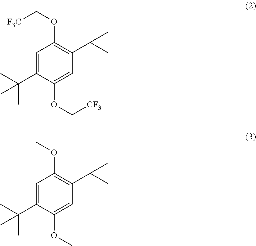
- the redox reactant of the catholye in some embodiments is selected from a 1,4-dialkoxybenzene compound (e.g., a 2,5-di-tert-butyl-1,4-dialkoxybenzene compound), a phenothiazine compound, a catechol ether compound, a catecholborane compound (e.g., a halogenated 5-phenyl-1,3,2-benzodioxaborole compound), a borane cluster compound (e.g., a halogen-substituted B 12 borane compound), a 1,3 benzodioxole compound (e.g., a 4,6-di-tert-butyl-1,3-benzodioxole), a benzodioxin compound (e.g., a 5,7-di-tert-butyl-benzodioxin, a 1,4-dialkoxy-2,5 bisphosphinyl benz
- the cation-permeable separator is adapted to allow cations to cross the membrane to balance out charges in the anolyte and catholyte that develop during the charging and discharging of the battery.
- the electrolyte salts can comprise, for example, alkali metal salts, alkaline earth salts, organic salts, and the like.
- the electrolyte salts utilized in anolyte and catholyte are alkali metal salts (e.g., lithium salts such as lithium tetrafluoroborate or lithium hexafluorophosphate, or sodium salts).
- organic solvents for use in the electrolytes include organic carbonates, such as ethylene carbonate, propylene carbonate, dimethyl carbonate, diethyl carbonate, and ethyl methyl carbonate; as well as, for example, ethers, esters, and nitriles.
- non-aqueous redox flow batteries utilizing transition metal-free redox reactants and electrolytes with cation-exchange capabilities provide an attractive alternative to existing aqueous flow batteries and flow batteries utilizing only transition metal-based redox materials.
- the performance capabilities of the non-aqueous redox flow batteries described herein can be tailored by selection of the particular redox reactant materials, by the choice of electrolyte salt (e.g., alkali metal salts, alkaline earth salts, organic salts, and the like), as well as by the choice of solvent, if any, utilized in the electrolyte compositions.
- Particularly advantageous positive redox materials for use in the redox flow batteries described herein include compounds of Formula (III):
- each of R 15 , R 16 , R 17 , and R 18 independently is a halogen (preferably each of R 15 , R 16 , R 17 , and R 18 is F) and each of R 19 and R 20 independently is alkyl (e.g., methyl or ethyl) or alkoxyalkyl (e.g., methoxyethyl).
- each of R 15 , R 16 , R 17 , and R 18 is F
- each of R 19 and R 20 is methyl, ethyl, or methoxyethyl (i.e., the compounds are tetrafluorohydroquinone ethers).
- each of X 9 , X 10 , X 11 , and X 12 independently is a halogen (preferably each of X 9 , X 10 , X 11 , and X 12 is F) and each of R 21 and R 22 independently is alkyl (e.g., methyl or ethyl) or alkoxyalkyl (e.g., methoxyethyl).
- each of X 9 , X 10 , X 11 , and X 12 is F
- each of R 21 and R 22 is methyl, ethyl, or methoxyethyl (i.e., the compounds are tetrafluorocatechol ethers).
- F substituents on the aromatic ring of the compounds of Formula (III) and Formula (V) are advantageous, because F is the smallest known electron-withdrawing group, the strong electron-withdrawing effect of F groups improves the redox potential of the compounds, the pi-donating character of F groups can stabilize the radical cation formed during redox reactions, and F groups can lead to better solubility.
- FIG. 1 provides a schematic illustration of an exemplary redox flow battery of the invention suitable for large-scale electrochemical energy storage.
- Species A and B represent generic negative and positive redox reactant electrode materials, respectively.
- Species C + represents a generic cation, which shuttles across a separator to maintain electroneutrality.
- FIG. 2 shows (A) cyclic voltammograms of 0.005 M 2,5-di-tert-butyl-1,4-bis(2-methoxyethoxy)benzene (DBBB) in Electrolyte A (1.2 M LiPF 6 in a mixture of ethylene carbonate (EC) and ethyl methyl carbonate (EMC) in a EC/EMC volume ratio of about 3/7) at varying scan rates.
- B Comparative cyclic voltammograms of 0.005 M DBBB in Electrolyte A and in Electrolyte B (0.2 M LiBF 4 in propylene carbonate (PC)) at 20 mV/s.
- the lighter dashed cyclic voltammograms in (B) represent the baseline of each electrolyte without any redox species. All evaluations were performed in a Pt/Li/Li cell at room temperature.
- FIG. 3 shows (A) cyclic voltammograms of 2,3-dimethylquinoxaline, 2-methylquinoxaline and quinoxaline; and (B) of 2,3-dimethylquinoxaline, 2,3-diphenylquinoxaline, and quinoxaline, show the impact of adding substituent groups to the nitrogen-containing ring. (C) Cyclic voltammograms of 6-methylquinoxaline, 5-methylquinoxaline, and quinoxaline show the impact of adding substituent groups to the benzene ring.
- FIG. 4 shows (A) charge-discharge curves of a coin cell flow battery using 0.05 M DBBB and 0.05 M 2,3,6-trimethylquinoxaline as the positive and negative electrode species. Representative charge-discharge profiles of the cell over (B) the first 4 cycles and (C) 14 th -17 th cycle.
- An electrolyte solution of 0.05 M DBBB and 0.05 M 2,3,6-trimethylquinoxaline in Electrolyte B was used for both the positive and negative compartments.
- FIG. 5 provides a table of redox potentials are determined by analysis of cyclic voltammograms over a range of scan rates. For all evaluations, the redox species concentration was 0.005 M in Electrolyte B, and studies were performed in Pt/Li/Li cell. All evaluations were performed in triplicate.
- FIG. 6 shows average redox peak potential of 0.005 M DBBB in Electrolyte A and Electrolyte B over a range of scan rates (5, 10, 20, 50, 100, and 200 mV/s). Evaluations were performed in triplicate in a Pt/Li/Li cell at room temperature.
- FIG. 7 shows the dependence of peak current on scan rate (5, 10, 20, 50, 100, and 200 mV/s) for 0.005 M DBBB in Electrolyte A and Electrolyte B. Evaluations were performed in triplicate in a Pt/Li/Li cell.
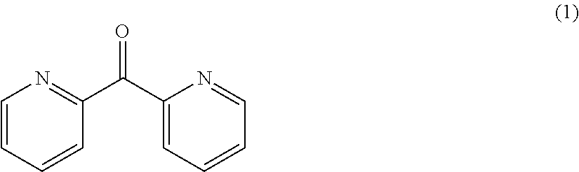
- FIG. 8 shows a cyclic voltammogram of 13 mM di-(2-pyridyl) ketone in an electrolyte containing 0.2 M LiPF 6 in propylene carbonate at 20 mV/s in a Pt/Li/Li cell at 20 mV/s.
- FIG. 9 shows cyclic voltammograms of di-(2-pyridyl) ketone in different electrolyte compositions at 20 mV/s in a Pt/Li/Li cell at 20 mV/s.
- FIG. 10 shows cyclic voltammograms of 10 mM 2,5-di-tert-butyl-1,4-bisalkoxybenzene (2) in Electrolyte C (1.2 M LiPF 6 in a mixture of ethylene carbonate (EC) and ethyl methyl carbonate (EMC) in a EC/EMC weight ratio of about 3/7) in a Pt/Li/Li cell at varying scan rates.
- Electrolyte C 1.2 M LiPF 6 in a mixture of ethylene carbonate (EC) and ethyl methyl carbonate (EMC) in a EC/EMC weight ratio of about 3/7) in a Pt/Li/Li cell at varying scan rates.
- FIG. 11 shows cyclic voltammograms of 10 mM 2,5-di-tert-butyl-1,4-dimethoxybenzene (3) in Electrolyte C in a Pt/Li/Li cell at varying scan rates.
- FIG. 12 provide a cyclic voltammograms of 13 mM phenothiazine (4) in Electrolyte B in a Pt/Li/Li cell at 20 mV/s.
- the lighter dashed cyclic voltammogram represents Electrolyte B without any redox species.
- FIG. 13 shows a cyclic voltammogram of 10 mM catechol ether (5) in Electrolyte C in a Pt/Li/Li cell at varying scan rates.
- FIG. 14 shows a cyclic voltammogram of 10 mM catechol phenylborate ester (6) in Electrolyte A in a Pt/Li/Li cell at 20 mV/s.
- the lighter dashed cyclic voltammogram represents Electrolyte A without any redox species.
- FIG. 15 shows a cyclic voltammogram of 10 mM catechol phenylborate ester (7) in Electrolyte A in a Pt/Li/Li cell at varying scan rates.
- FIG. 16 shows a cyclic voltammogram of 10 mM catechol phenylborate ester (8) in Electrolyte A in a Pt/Li/Li cell at varying scan rates.
- FIG. 17 shows a cyclic voltammogram of 10 mM borane cluster (9) in Electrolyte C in a Pt/Li/Li cell at varying scan rates.
- FIG. 18 shows a cyclic voltammogram of 10 mM borane cluster (10) in Electrolyte C in a Pt/Li/Li cell at varying scan rates.
- FIG. 19 shows a cyclic voltammogram of benzophenone in (A) Electrolyte A; (B) LiBETI and PC; (C) LiTFSI and PC, and (D) Lithium triflate and PC, each in a Pt/Li/Li cell at 20 mV/s.
- the lighter dashed cyclic voltammograms in (A), (B) and (C) represent the electrolyte baselines without any redox species.
- FIG. 20 shows a cyclic voltammogram of (A) 8 mM bis-benzyl viologen dichloride, and (B) 11 mM bis-ethyl viologen diperchlorate, each in Electrolyte B in a Pt/Li/Li cell at 20 mV/s.
- the lighter dashed cyclic voltammograms in (A) and (B) represent Electrolyte B without any redox species.
- FIG. 21 shows a cyclic voltammogram of 11 mM 5,10-dihydro-5,10-dimethylphenazine in Electrolyte A in a Pt/Li/Li cell at 20 mV/s.
- the lighter dashed cyclic voltammogram represents Electrolyte A without any redox species.
- FIG. 22 shows cyclic voltammograms of (A) 17 mM DBBB in 0.247 M NaPF 6 in PC in a Pt/Na/Na cell at varying scan rates; and of (B) 13 mM 2,3,6-trimethylquinoxaline in 0.217 M NaPF 6 in PC in a Pt/Na/Na cell at 20 mV/s.
- FIG. 23 shows a cyclic voltammogram of 11 mM 6,7-dimethyl-2,3-di(2-pyridyl)quinoxaline evaluated in Electrolyte B in a Pt/Li/Li cell at 20 mV/s.
- the lighter dashed cyclic voltammogram represents Electrolyte B without any redox species.
- the flow battery comprises, consists essentially of, or consists of a negative electrode immersed in an anolyte, a positive electrode immersed in a catholyte, and a cation-permeable separator to allow cations to shuttle between the anolyte and the catholyte during charging and discharging.
- the negative electrode and positive electrode each act as current collectors.
- the anolyte and catholyte each comprises, consists essentially of, or consists of an electrolyte salt and a transition metal-free redox reactant.
- the salt and redox reactant are dissolved in an electrochemically stable organic solvent.
- the redox reactant is a liquid material.
- the redox reactant of the catholyte is selected to have a higher redox potential than the redox reactant of the anolyte.
- the cation component of the electrolyte salts shuttles between the anolyte and the catholyte through the cation-permeable separator to balance charges that develop during the oxidation and reduction of the redox materials.
- the electrolyte salt components of the anolyte and catholyte can be any electrochemically stable salt.
- the electrolytes can include a single salt or a combination of two or more salts.
- the cation component of the salt can be any monovalent (e.g., Li + , Na + , Ag + , Cu + , NH 4 + , and the like) or multivalent cation (e.g., Mg 2+ , Ca 2+ , CU 2+ , Zn 2+ , and the like).
- the cation comprises an alkali metal ion, an alkaline earth metal ion, and/or an organic cation.
- alkali metal cations include lithium and sodium.
- Non-limiting examples of alkaline earth metal ions include magnesium and calcium.
- Non-limiting examples of organic cations include tetraalkyl ammonium ions.
- the anionic component of the electrolyte salts can be any anion suitable for use in non-aqueous electrolytes for lithium or sodium ion-type batteries.
- BF 4 ⁇ tetrafluoroborate ion
- bis(trifluoromethanesulfonyl)imide (TFSI) ion (N(SO 2 CF 3 ) 2 ⁇ ) can be utilized as the anion component of the electrolyte salt in the catholyte.
- the electrolyte salts of the anolyte and catholyte can be different materials or can be composed of the same material or materials.
- Non-limiting examples of some preferred salts include, e.g., LiBF 4 , LiPF 6 , lithium triflate, NaBF 4 , NaPF 6 , and sodium triflate.
- the electrochemically stable organic solvent components of the negative and positive electrolytes can be composed of a single solvent or a combination of two or more solvents.
- the solvent or solvents of the anolyte can be the same as the solvent or solvents of the catholyte, or the anolyte and catholyte can comprise different solvents.
- the redox reactant of one or both of the anolyte and catholyte can be a liquid material and, if desired, a solvent can be omitted. Any organic solvents that are suitable for use in non-aqueous alkali metal ion (e.g., lithium ion) batteries, for example, can be utilized.
- Such solvents are well known in the battery art, and include, for example, organic carbonates (e.g., ethylene carbonate, propylene carbonate, ethyl methyl carbonate, and the like), ethers (e.g., diethyl ether, tetrahydrofuran, 2-methyl tetrahydrofuran, dimethoxyethane, and 1,3 dioxolane), esters (e.g., methyl formate, gamma-butyrolactone, and methyl acetate), and nitriles (e.g., acetonitrile).
- organic carbonates e.g., ethylene carbonate, propylene carbonate, ethyl methyl carbonate, and the like
- ethers e.g., diethyl ether, tetrahydrofuran, 2-methyl tetrahydrofuran, dimethoxyethane, and 1,3 dioxolane
- esters e.g.,
- the solvents comprise, consist essentially of, or consist of one or more organic carbonates such as ethylene carbonate (EC), propylene carbonate (PC), dimethyl carbonate (DMC), diethyl carbonate (DEC), ethyl methyl carbonate (EMC), or a combination of two or more of the foregoing carbonates.
- organic carbonates such as ethylene carbonate (EC), propylene carbonate (PC), dimethyl carbonate (DMC), diethyl carbonate (DEC), ethyl methyl carbonate (EMC), or a combination of two or more of the foregoing carbonates.
- examples of some preferred solvents include propylene carbonate, and mixtures of ethylene carbonate and ethyl methyl carbonate in an EC/EMC volume or weight ratio of about 3/7.
- the negative electrode of the battery is positioned within a negative electrolyte chamber (“NE chamber”) that contains the negative electrolyte (i.e., anolyte).
- the NE chamber is defined by a first housing or enclosure.
- the NE chamber is adapted to communicate with a first negative electrolyte reservoir (“NE reservoir”) and a second NE reservoir (e.g., via openings, valves, tubing, and the like to connect the interior of the housing/enclosure with the interior of the reservoirs).
- NE reservoir negative electrolyte reservoir
- second NE reservoir e.g., via openings, valves, tubing, and the like to connect the interior of the housing/enclosure with the interior of the reservoirs.
- the first NE reservoir, the NE chamber, and the second NE reservoir together define a negative electrolyte circulation pathway.
- a pump is operably positioned within the negative electrolyte circulation pathway to facilitate circulation of the negative electrolyte back and forth between the first NE reservoir and the second NE reservoir over the negative electrode.
- the pump can be positioned in any convenient location in the negative electrolyte flow pathway (e.g., between the first NE reservoir and the NE chamber, between the second NE reservoir and the NE chamber, or integral with a portion of the NE chamber or NE reservoirs).
- the negative electrode can comprise, consist essentially of, or consist of a metal (e.g., platinum, copper, aluminum, nickel or stainless steel), a carbon material (e.g., carbon black, activated carbon, amorphous carbon, graphite, graphene, or a nanostructured carbon material), or a combination thereof.
- the electrode can be porous, fluted, or smooth.
- the positive electrode of the battery is positioned within a positive electrolyte chamber (“PE chamber”), which contains the positive electrolyte (i.e., catholyte).
- the PE chamber is defined by a second housing or enclosure.
- the PE chamber is adapted to communicate with a first positive electrolyte reservoir (“PE reservoir”) and a second PE reservoir (e.g., via openings, valves, tubing, and the like to connect the interior of the housing/enclosure with the interior of the reservoirs).
- PE reservoir positive electrolyte reservoir
- the first PE reservoir, the PE chamber, and the second PE reservoir together define a positive electrolyte circulation pathway.
- a pump is operably positioned within the positive electrolyte circulation pathway to facilitate circulation of the positive electrolyte back and forth between the first PE reservoir and the second PE reservoir over the positive electrode.
- the pump can be positioned in any convenient location in the positive electrolyte flow pathway (e.g., between the first PE reservoir and the PE chamber, between the second PE reservoir and the PE chamber, or integral with a portion of the PE chamber or PE reservoirs).
- the positive electrode can comprise, consist essentially of, or consist of a metal (e.g., platinum, copper, aluminum, nickel or stainless steel), a carbon material (e.g., carbon black, activated carbon, amorphous carbon, graphite, graphene, or a nanostructured carbon material), or a combination thereof.
- the electrode can be porous, fluted, or smooth.
- Pumps suitable for use in the flow batteries described herein include internal gear pumps, screw pumps, shuttle block pumps, flexible vane pumps, sliding vane pumps, circumferential piston pumps, helical twisted root pumps, piston pumps, diaphragm pumps, peristaltic pumps, centrifugal pumps, and the like, which are well known in the liquid pumping art.
- the utility of a given pump will be dependent on the chemical resistance of the pump to the electrolyte components in contact therewith (i.e., materials compatibility).
- a cation-permeable separator is situated between the NE chamber and the PE chamber.
- the separator is adapted to allow cations to flow back and forth between the negative and positive electrolytes upon charging and discharging of the battery.
- the separator can be, for example, a cation-permeable membrane, sheet, panel, or film that is permeable to the cations of the electrolytes.
- the separator is at least partially impermeable to the redox components of the electrolytes, although this is not an absolute requirement for the batteries of the present invention.
- the first and second housings or enclosures for the electrodes are integral with one another, and the cation-permeable separator is mounted as an internal partition separating the NE chamber from the PE chamber.
- the first and second housings can be separate components that include perforations or openings that contact the separator, such that cations can flow between the NE chamber and the PE chamber, optionally along with some of the solvent and or redox component, and the separate housings are sealed, e.g. by gaskets, around the partition.
- Non-limiting examples of suitable separator materials include, NAFION® type ion exchange membranes (sulfonated tetrafluoroethylene-based fluoropolymer-copolymers), other porous polymeric materials such as, for example, sulfonated poly(ether ether ketones), polysulfones, polyethylene, polypropylene, ethylene-propylene copolymers, polyimides, polyvinyldifluorides, and the like, which can be in the form of membranes, matrix-supported gels, sheets, films, or panels.
- Other suitable materials include porous ceramics, porous insulated metals, cation-conducting glasses, and zeolites.
- the separator can be an interface between immiscible liquids.
- a porous film, panel, or mesh might be included to aid in maintaining separation between the liquids (e.g., as a physical support or guide to aid in maintaining laminar flow at the interface).
- an electric potential is applied to the negative and positive electrodes, while simultaneously pumping the negative electrolyte (anolyte) over the negative electrode from the first NE reservoir to the second NE reservoir, and pumping the positive electrolyte (catholyte) over the positive electrode from the first PE reservoir to the second PE reservoir. Cations flow across the cation-permeable separator to balance the charges.
- the negative redox reactant is reduced and stored in the second NE reservoir, while the positive redox reactant is oxidized and stored in the second PE reservoir. In this way, energy can be stored by charging the battery from an energy source during off-peak usage periods.
- the electrodes are placed in a circuit (e.g., with a power grid) and the direction of electrolyte flow is reversed, with the stored reduced negative redox reactant being pumped over the negative electrode back into the first NE reservoir, and the stored oxidized positive redox reactant being pumped over the positive electrode back into the first PE reservoir. Cations again flow across the cation-permeable separator (in the opposite direction) to balance the charges.
- the energy stored in the system can thus be directly used to perform work or can be transferred back into the power grid during peak usage periods to supplement the power supply.
- An AC/DC converter can be used to facilitate transfer of energy to and from an AC power grid.
- the transition metal-free redox reactants are independently selected from the group consisting of an organic compound comprising a conjugated unsaturated moiety, a boron cluster compound, and a combination thereof, wherein the conjugated unsaturated moiety is aromatic, non-aromatic, or a combination thereof, and comprises carbon-carbon unsaturated bonds, carbon-heteroatom unsaturated bonds, or a combination of carbon-carbon and carbon-heteroatom unsaturated bonds, and wherein the heteroatom is a non-metallic heteroatom or a metalloid heteroatom.
- the redox reactant component of the negative electrolyte is selected from the group consisting of a quinoxaline compound (e.g., an alkyl-substituted or alkoxy-substituted quinoxaline compound), a dipyridyl ketone (e.g., di-(2-pyridyl) ketone and derivatives thereof bearing at least one electron donating substituent), a viologen compound (e.g., bis-benzyl viologen dichloride, ethyl viologen diperchlorate), and a benzophenone compound.
- a quinoxaline compound e.g., an alkyl-substituted or alkoxy-substituted quinoxaline compound
- a dipyridyl ketone e.g., di-(2-pyridyl) ketone and derivatives thereof bearing at least one electron donating substituent
- a viologen compound e.g., bis-benzyl
- the redox reactant component of the positive electrolyte is selected to have a redox potential which is higher than that of the redox potential of the redox reactant in the negative electrolyte.
- redox reactants suitable for use in the positive electrolyte include a 1,4-dialkoxy benzene compound (e.g., a 2,5-di-tert-butyl-1,4-dialkoxy benzene), a phenothiazine compound, a catechol ether compound, a catecholborane compound (e.g., a B-phenylcatecholborane compound), a borane cluster compound (e.g., a lithium halogen-substituted borane cluster), a 1,3-benzodioxole compound, a benzodioxin compound, a 1,4-dialkoxybisphosphinyl benzene compound, a 1,4-phenylene diphosphate ester compound, and
- the organic redox reactant component of the negative electrolyte comprises a quinoxaline compound of Formula (I):
- each R substituent independently is selected from the group consisting of H, alkyl (preferably C 1 to C 4 alkyl, e.g., methyl or ethyl), phenyl, pyridyl, alkoxy (preferably C 1 to C 4 alkoxy, such as methoxy or ethoxy), halogen (e.g., Cl or F), and amino.
- each R substituent is selected from the group consisting of H, alkyl, and alkoxy.
- the various R substituents can be selected, e.g., to adjust the redox potential, reactivity, and solubility thereof (i.e., R 1 , R 2 , R 3 , R 4 , R 5 , and R 6 need not all be the same).
- at least one (i.e., 1, 2, 3 or 4) of R 1 , R 2 , R 3 and R 4 is a methyl substituent, and the remaining R groups are H.
- R 1 , R 2 , and R 3 are methyl groups and the remaining R groups are H.
- Phenyl substituents when present, preferably are R 1 and/or R 2 substituents.
- the organic redox reactant component of the negative electrolyte comprises a dipyridyl ketone of Formula (II):
- each R substituent independently is selected from the group consisting of H, halogen (e.g., Cl or F), alkyl (preferably C 1 to C 4 alkyl, e.g., methyl or ethyl), phenyl, and alkoxy (preferably C 1 to C 4 alkoxy, such as methoxy or ethoxy), and amino.
- each R substituent is H.
- each R substituent is selected from H, alkyl, and alkoxy.
- the various R substituents can be selected, e.g., to adjust the redox potential, reactivity, and solubility thereof.
- the organic redox material of the negative electrolyte comprises a viologen compound (i.e., an N,N′-dialkylated 4,4′-bipyridinium compound), for example, bis-benzylviologen dichloride, bis-ethylviologen diperchlorate, and the like.
- a viologen compound i.e., an N,N′-dialkylated 4,4′-bipyridinium compound
- bis-benzylviologen dichloride bis-ethylviologen diperchlorate, and the like.
- the organic redox material of the negative electrolyte also can comprise a benzophenone compound, e.g., benzophenone or a derivative thereof bearing one of more substituents such as alkyl, phenyl, alkoxy, halogen, amino, and the like.
- a benzophenone compound e.g., benzophenone or a derivative thereof bearing one of more substituents such as alkyl, phenyl, alkoxy, halogen, amino, and the like.
- the organic redox reactant component of the positive electrolyte comprises 1,4-dialkoxybenzene compound of Formula (III):
- each of R 15 , R 16 , R 17 , and R 18 independently is selected from the group consisting of H, halogen, alkyl, fluoroalkyl, alkoxy-substituted alkyl, phenyl, and amino; and each of R 19 and R 20 independently is selected from the group consisting of alkyl (preferably C 1 to C 4 alkyl, e.g., methyl or ethyl), fluoroalkyl (e.g., trifluoromethyl or 2,2,2-trifluoroethyl), and alkoxy-substituted alkyl (preferably C 1 to C 4 alkoxy, e.g., methoxy or ethoxy substituted), such as a 2-methoxyethyl group.
- alkyl preferably C 1 to C 4 alkyl, e.g., methyl or ethyl
- fluoroalkyl e.g., trifluoromethyl or 2,2,2-trifluoroeth
- R 19 and R 20 each are methyl, 2,2,2-trifluoroethyl (—CH 2 CF 3 ), or 2-methoxyethyl (—CH 2 CH 2 OCH 3 ); and/or each of R 15 and R 17 is H, and each of R 16 and R 18 is tert-butyl.
- the various substituents can be selected, e.g., to adjust the redox potential, reactivity, and solubility thereof.
- each of R 15 , R 16 , R 17 , and R 18 independently is a halogen (preferably each of R 15 , R 16 , R 17 , and R 18 is F) and each of R 19 and R 20 independently is alkyl (e.g., methyl or ethyl) or alkoxyalkyl (e.g., methoxyethyl).
- each of R 15 , R 16 , R 17 , and R 18 is F
- each of R 19 and R 20 is methyl, ethyl, or methoxyethyl.
- F substituents on the aromatic ring of Formula (III) are advantageous, because F is the smallest known electron-withdrawing group, the strong electron-withdrawing effect of F groups improves the redox potential of the compounds, the pi-donating character of F groups can stabilize the radical cation formed during redox reactions, and F groups can lead to better solubility.
- the organic redox reactant component of the positive electrolyte comprises a phenothiazine compound of Formula (IV):
- each X substituent independently is selected from the group consisting of H, halogen (e.g., Cl or F), alkyl (preferably C 1 to C 4 alkyl, e.g., methyl or ethyl), phenyl, and alkoxy (preferably C 1 to C 4 alkoxy, e.g., methoxy or ethoxy), and amino.
- each of the X substituents is H.
- the various substituents can be selected, e.g., to adjust the redox potential, reactivity, and solubility thereof.
- the organic redox reactant component of the positive electrolyte comprises a catechol ether of Formula (V) or catechol phenylborate ester of Formula (VI):
- each X substituent i.e., X 9 through X 21
- each R substituent independently is selected from the group consisting of H, alkyl (preferably C 1 to C 4 alkyl, e.g., methyl or ethyl), phenyl, and alkoxy-substituted alkyl (preferably C 1 to C 4 alkoxy, e.g., methoxy or ethoxy substituted), such as a 2-methoxyethyl group
- R 21 and R 22 together form an alkylene group, preferably a —CH 2 —, or —CH 2 CH 2 — group, optionally substituted with one or more alkyl group in place of a hydrogen.
- each of X 9 through X 12 is F and R 21 and R 22 together form a —CH 2 CH 2 — group.
- each of X 13 through X 16 is F and at least two of X 17 through X 21 is F or CF 3 .
- the various substituents can be selected, e.g., to adjust the redox potential, reactivity, and solubility thereof.
- each of X 9 , X 10 , X 11 , and X 12 independently is a halogen (preferably each of X 9 , X 10 , X 11 , and X 12 is F) and each of R 21 and R 22 independently is alkyl (e.g., methyl or ethyl) or alkoxyalkyl (e.g., methoxyethyl).
- each of X 9 , X 10 , X 11 , and X 12 is F
- each of R 21 and R 22 is methyl, ethyl, or methoxyethyl.
- F substituents on the aromatic ring of Formula (V) are advantageous for the same reasons as described with respect to the compounds of Formula (III), supra.
- the organic redox reactant component of the positive electrolyte comprises lithium halogen-substituted borane cluster of Formula (VII): Li 2 B 12 X 22 n H (12-n) (VII)
- n is an integer in the range of 1 to 12; and each X 22 independently is a halogen substituent (e.g., Cl or F). Preferably, n is 9, 10, 11, or 12.
- FIG. 1 schematically illustrates a non-aqueous redox flow battery of the present invention.
- the redox flow battery comprises negative electrode 102 within negative electrolyte chamber (NE chamber) 104 , defined by housing 106 .
- First negative electrolyte reservoir (NE reservoir) 108 is in fluid-flow communication with NE chamber 104 via pipe 107 .
- Second NE reservoir 110 is operably connected to pump 112 via pipe 109 , while pump 112 also is operably connected to NE chamber 104 via pipe 111 .
- Pump 112 is adapted to facilitate transfer of negative electrolyte back and forth between first NE reservoir 108 to second NE reservoir 110 through NE chamber 104 , such that the flowing electrolyte contacts negative electrode 102 .
- the battery also includes a positive electrode 114 within positive electrolyte chamber (PE chamber) 118 , defined by housing 116 .
- First positive electrolyte reservoir (PE reservoir) 120 is in fluid-flow communication with PE chamber 118 via pipe 117 .
- Second PE reservoir 122 is operably connected to pump 124 via pipe 119 , while pump 124 also is operably connected to PE chamber 118 via pipe 121 .
- Pump 124 is adapted to facilitate transfer of positive electrolyte back and forth between first PE reservoir 120 to second PE reservoir 122 through PE chamber 118 , such that the flowing electrolyte contacts positive electrode 114 .
- Cation-permeable separator 126 separates NE chamber 104 from PE chamber 118 , and allows passage of cations (C + ) back and forth between the positive and negative electrolytes to balance out charges that form during oxidation and reduction of materials within the electrolytes.
- an electric potential is applied to the negative electrode 102 and positive electrode 114 , e.g., from an energy source 130 via AC/DC converter 128 , while simultaneously pumping the negative electrolyte over negative electrode 102 from first NE reservoir 108 to second NE reservoir 110 , and simultaneously pumping the positive electrolyte over the positive electrode from the first PE reservoir 120 to the second PE reservoir 122 .
- Cations (C + ) pass through cation-permeable separator 126 to balance the charges.
- a negative redox reactant material (represented by A/A ⁇ C + ) and a positive redox reactant material (represented by B/B ⁇ C + ) in the electrolytes undergo redox reactions upon contact with the electrodes such that the reduced form of A is stored in second NE reservoir 110 , while the oxidized form of B is stored in the second PE reservoir 122 .
- energy can be stored by charging the battery from energy source 130 during off-peak usage periods.
- the electrodes are placed in a circuit (e.g., with a power grid 132 ) and the direction of electrolyte flow is reversed, with the stored reduced negative electrolyte being pumped over negative electrode 102 back into first NE reservoir 108 , and the stored oxidized positive electrolyte being pumped over positive electrode 114 back into first PE reservoir 120 .
- Cations again transfer through cation-permeable separator 126 (in the opposite direction) to balance the charges resulting from redox reactions at the electrodes.
- the energy stored in the system during charging can thus be directly used to perform work or can be transferred into power grid 132 during peak usage periods to supplement the power supply.
- AC/DC converter 128 again can be used to facilitate transfer of energy to an AC power grid.
- DBBB 2,5-Di-tert-butyl-1,4-bis(2-methoxyethoxy)benzene
- DBBB 2,5-Di-tert-butyl-1,4-bis(2-methoxyethoxy)benzene
- FIG. 2 a shows the cyclic voltammograms of 0.005 M DBBB dissolved in an electrolyte consisting of 1.2 M LiPF 6 in ethylene carbonate/ethyl methyl carbonate at a volume ratio of about 3 to 7 (“Electrolyte A”) at scan rates ranging from 5 to 200 mV/s.
- DBBB displays a well-defined reversible redox couple with a redox potential of about 3.927 V vs. Li/Li + , based on the average of the anodic and cathodic redox potentials [(E pa +E pc )/2].
- the diffusion coefficient of DBBB was determined to be about 1.30 ⁇ 10 ⁇ 6 cm 2 /s in the battery electrolyte based on Randle-Sevcik measurements [20].
- Electrolyte A is non-ideal for flow battery applications due to high volatility, extreme moisture sensitivity, and high materials cost.
- an electrolyte consisting of 0.2 M LiBF 4 in propylene carbonate (“Electrolyte B”) was also investigated as a more robust and lower cost alternative.
- FIG. 2 b show iR-corrected cyclic voltammograms of 0.005 M DBBB in Electrolyte A and in Electrolyte B at a scan rate of 20 mV/s.
- Quinoxaline-derivatives have been reported as component materials in organic sensitizers for dye-sensitized solar cells [24] and in lower band gap polymers for organic photovoltaics [25].
- Matsunaga et al. recently reported solid state triquinoxalinylene as an organic cathode material for Li-ion batteries with 3 quinoxaline subunits undergoing a reversible 6 electron transfer [26].
- Quinoxaline is useful as a negative redox material in the redox flow batteries described herein due, at least in part, to its high solubility ( ⁇ 2 M in propylene carbonate), its low molecular weight, and its ability to transfer 2 electrons per molecule.
- To determine structure-activity relationships a series of quinoxaline-derivatives with different substituent groups and varying substituent locations were investigated.
- FIG. 3 a shows that substituting electron donating methyl groups onto the 2 and 3 positions of quinoxaline lowered redox potential of both electron transfer events and enhanced redox activity. While phenyl group substitutions on the nitrogen-bearing ring also enhanced redox activity, this substitution's effects on redox potential were mixed, in that the upper redox event occurred at a lower potential while the lower redox event occurred at a higher potential as compared to quinoxaline ( FIG. 3 b ). Methyl groups were also substituted on the 5 and 6 position of the quinoxaline ( FIG. 3 c ). The 6-methylquinoxaline showed slightly better performance than quinoxaline, whereas 5-methylquinoxaline demonstrated lower activity.
- the upper and lower redox potentials shown in FIG. 5 were determined by a combination of average peak potential and graphical analysis of the cyclic voltammograms over a range of scan rates (5, 10, 20, 50, 100, and 200 mV/s).
- the average peak potential method (described herein below) was used.
- the average peak potential was estimated via graphical analysis of the cyclic voltammograms.
- FIG. 23 shows a cyclic voltammogram of about 11 mM 6,7-dimethyl-2,3-di(2-pyridyl)quinoxaline evaluated in Electrolyte B in a Pt/Li/Li cell at a scan rate of 20 mV/s, which exhibited a lower redox potential of about 2.6 V, and an upper redox potential in the range of about 2.8 to 2.9V, i.e., similar to those in FIG. 5 .
- an all-organic Li ion-based redox flow battery can be constructed using a 2,5-di-tert-butyl-1,4-dialkoxybenzene compound such as DBBB and a quinoxaline compound such as 2,3,6-trimethylquinoxaline as positive and negative electrode materials, respectively ( FIG. 4 ).
- DBBB 2,5-di-tert-butyl-1,4-dialkoxybenzene compound
- quinoxaline compound such as 2,3,6-trimethylquinoxaline
- Electrolyte B Both carbon electrodes, which function as current collectors, were pre-soaked in an electrolyte solution consisting of 0.05 M DBBB and 0.05 M 2,3,6-trimethylquinoxaline in Electrolyte B.
- FIG. 4 a shows stable coin cell performance of the cell over the course of 30 discharge-charge cycles (several days). Over the first four cycles, the coin cell transitions from a lower potential charge feature of 1.2-1.8 V to a higher potential charge feature of 1.8-2.4 V. This transition corresponds to the growth of the higher potential discharge feature near 1.5 V and the reduction of the lower potential discharge feature near 0.6 V ( FIG. 4 b ). After this initial acclimatization period, the cell charged and discharged at a voltage in the range of about 1.8-2.4 V and 1.6-1.3 V, respectively, for 30 cycles.
- FIG. 4 c shows a representative set of voltage-time profiles.
- the first cycle efficiency is about 43%, after which the coulombic efficiency increases to about 70-75% which compares favorably with previously-reported efficiencies for non-aqueous flow batteries [8-11]. These efficiencies are expected to increase with advances in cell design and operation (e.g., pre-charging electrolytes), as well as improvements in materials design (e.g., non-aqueous membranes).
- electroactive organic species offers significant opportunities for the design and synthesis of redox flow batteries with tailorable redox potentials and activities. Furthermore, the choice of electrolyte can have significant effects on the performance of each redox species depending on solution-phase interactions. Optimization of the electrolyte-redox species relationship can be performed based on the cost and safety of each electrolyte system under consideration.
- Electrolyte A 1.2 M lithium hexafluorophosphate in a mixture of ethylene carbonate and ethyl methyl carbonate at a volume ratio of about 3 to 7 (Tomiyama High Purity Chemical Industries Ltd.); Electrolyte B: 0.2 M lithium tetrafluoroborate (98% pure, anhydrous, Acros Organics) in propylene carbonate (99.7% pure, anhydrous, Aldrich); and Electrolyte C, 1.2 M lithium hexafluorophosphate in a mixture of ethylene carbonate and ethyl methyl carbonate at a weight ratio of about 3 to 7 (Tomiyama High Purity Chemical Industries Ltd.). All chemicals were used as received and stored in an Argon-filled glove box. All solutions were prepared in the glove box.
- Cyclic voltammetry were performed in a custom-made airtight three-electrode electrochemical cell with a 2-mm diameter platinum disk working electrode and lithium metal counter and reference electrodes.
- the platinum disk electrode Prior to use, the platinum disk electrode was dipped in nitric acid solution (about 50 vol % HNO 3 , Ricca Chemical Company) and then polished on a MICROCLOTH® pad with 0.3 ⁇ m and 0.05 ⁇ m alumina (Buehler Ltd., Lake Bluff, Ill.). After polishing, the electrode was thoroughly rinsed with distilled water and dried with house nitrogen. The electrochemical cell was then assembled in an Argon-filled glove box and transferred out to perform measurements. Evaluations were performed on a 1470E Solartron Analytical Instrument at scan rates of 5, 10, 20, 50, 100, and 200 mV/s. All evaluations were performed in triplicate at room temperature.
- Charge-discharge studies were performed using a modified Li-ion coin cell with a NAFION® 117 membrane (Aldrich, about 2 cm 2 geometric surface area) between two carbon paper electrodes (SPECTRACARB® 2050A, 0.22 g/cm 3 density, 0.06 cm thickness, about 1.6 cm 2 geometric surface area).
- NAFION® membrane Prior to assembly, the NAFION® membrane was soaked in solutions of propylene carbonate and 0.2 M LiBF 4 in propylene carbonate for several days.
- the positive and negative carbon paper electrodes were soaked in the same solution of 0.05 M DBBB, 0.05 M 2,3,6-trimethylquinoxaline, 0.2 M LiBF 4 , in propylene carbonate for about 1 to 2 hours prior to use.
- the coin cell was assembled and sealed in an Argon-filled glove box and transferred out to perform measurements. Testing was performed using a battery cycler (Maccor) at room temperature. The cell was cycled between 0.1 and 2.5 V at a charge/discharge current of 0.1 mA, corresponding to a current density of about 0.0625 mA/cm 2 , for 50 cycles.
- Maccor battery cycler
- the redox potential of DBBB was calculated by averaging the oxidation and reduction peak potentials in the two different electrolytes at various scan rates (5, 10, 20, 50, 100, and 200 mV/s). As shown in FIG. 2 a , with increasing scan rate the oxidation and reduction peak potentials shift to higher and lower potentials, respectively.
- the shift in the peak potential with the scan rate may be caused by the limited charge-transfer kinetics of the active species (DBBB) and the uncompensated resistance, which is commonly called the “iR drop”.
- FIG. 6 shows the average redox peak potential of 0.005 M DBBB in Electrolyte A and Electrolyte B over a range of scan rates (5, 10, 20, 50, 100, and 200 mV/s). Evaluations were performed in triplicate in a Pt/Li/Li cell at room temperature.
- dipyridyl ketones also are useful as redox reactant components of the negative electrolyte.
- the redox activity of di-(2-pyridyl) ketone (1) is useful as redox reactant components of the negative electrolyte.
- FIG. 8 shows a cyclic voltammogram of 13 mM di-(2-pyridyl) ketone in this electrolyte at a scan rate of about 20 mV/s in a Pt/Li/Li cell at room temperature.
- FIG. 9 shows cyclic voltammograms of di-(2-pyridyl) ketone in different electrolyte compositions at a scan rate of about 20 mV/s in a Pt/Li/Li cell at room temperature.
- the di-(2-pyridyl) ketone concentration was in the range of 10 to 20 mM.
- the electrolytes evaluated included 0.2 M LiPF 6 in PC, Electrolyte A, Electrolyte B, and 0.2 M lithium bis(trifluoromethanesulfonyl)imide (LiTFSI) in PC.
- LiPF 6 LiPF 6
- Electrolyte A LiPF 6
- Electrolyte B 0.2 M lithium bis(trifluoromethanesulfonyl)imide
- LiTFSI lithium bis(trifluoromethanesulfonyl)imide
- FIG. 19 and FIG. 20 provide cyclic voltammograms of two additional negative redox materials, i.e., benzophenone ( FIG. 19 ) and viologen compounds (bis-benzyl-4,4′-bipyridinium dichloride and bis-ethyl-4,4′-bipyridinium diperchlorate; FIG. 20 ).
- Benzophenone was evaluated at a concentration of about 29 mM in Electrolyte A ( FIG. 19(A) ), 15 mM in 0.2 M LiBETI in PC ( FIG. 19(B) ), 23 mM in 0.2 M LiTFSI in PC ( FIG. 19(C) ), and 34 mM in 0.2 M Li triflate in PC ( FIG.
- the redox activity of other 2,4-di-tert-butyl-1,4-dialkoxybenzene compounds were evaluated under conditions similar to those described above for DBBB.
- Phenothiazine compounds e.g., Compound (4), also are useful as positive redox materials.
- the redox activity of phenothiazine (4) is illustrated by the cyclic voltammogram shown in FIG. 12 , taken with about a 13 mM concentration of compound (4) in Electrolyte A described above, in a Pt/Li/Li cell at 20 mV/s scan rate.
- Catechol ether (5) and catechol phenylborate esters (6), (7) and (8) also have redox properties suitable for use as redox reactants for the positive electrolyte.
- FIGS. 13, 14, 15, and 16 The redox activities of compounds (5), (6), (7) and (8) are illustrated by the cyclic voltammograms shown in FIGS. 13, 14, 15, and 16 , respectively.
- FIG. 13 is taken in Electrolyte C, described above
- FIGS. 14, 15 and 16 are taken in Electrolyte A, described above. All evaluations are performed in a Pt/Li/Li cell at various scan rates using protocols similar to those used for the other examples discussed herein.
- the concentration of compounds (5), (6), (7), and (8) were about 10 mM each.
- Lithium halogen-substituted borane cluster compounds such as Li 2 B 12 F 9 H 3 (9) and Li 2 B 12 F 12 (10) also can be used as redox reactants in the positive electrolytes.
- Cyclic voltammograms of compounds (9) and (10) in Electrolyte C, described above, in a Pt/Li/Li cell at various scan rates using protocols similar to those used for the other examples discussed herein, are shown in FIGS. 17 and 18 , respectively.
- the concentration of compounds (9) and (10) were about 10 mM each.
- a 5,10-dihydro-5,10-dialkylphenazine compound i.e., 5,10-dihydro-5,10-dimethylphenazine
- FIG. 21 provides the cyclic voltammogram obtained from this evaluation, which demonstrates suitable redox properties for use in the present invention.
- lithium-ion battery redox shuttle materials such as a halogenated 5-phenyl-1,3,2-benzodioxaborole compound (e.g., 2-(pentafluorophenyl)-tetrafluoro-1,3,2-benzodioxaborole), a 4,6-di-tert-butyl-1.3-benzodioxole compound (e.g., 4,6-di-tert-butyl-1,3,-benzodioxole), a 5,7-di-tert-butyl-benzodioxin compound (e.g., 5,7-di-tert-butyl-benzodioxin), a 1,4-dialkoxy-2,5 bisphosphinyl benzene compound (e.g., 1,4-dimethoxy-2,5-bis[bis(1-methylethyl)phosphinyl]-benzene), and a 2,5-di-tert-
- TFDMB 1,2,4,5-tetrafluoro-3,6-dimethoxybenzene
- TFDEB 1,2,4,5-tetrafluoro-3,6-diethoxybenzene
- TFBMEB 1,2,4,5-tetrafluoro-3,6-bis(2-methoxyethoxy)benzene
- TFBMEB is a liquid at ambient room temperature, which is particularly advantageous for use in the redox flow batteries described herein, since auxiliary solvent can be minimized or eliminated.
- TFDMB, TFDEB, and TFBMEB exhibited high potential (4.6 to 4.7 V), reversible redox behavior when evaluated at a 10 mM concentration in an electrolyte comprising 1.2 M LiPF 6 in EC/EMC (3:7 by weight) at various scan rates (10 mV to 500 mV) using Pt/Li/Li electrodes.
- Table 1 provides a summary of the useful redox properties of these compounds.
- FIG. 22 ( a ) provides a cyclic voltammogram obtained with about 17 mM DBBB in 0.247 M Na PF 6 in propylene carbonate, in a Pt/Na/Na cell at scan rates of 5, 20, 50, and 100 mV/s.
- FIG. 22 ( b ) provides a cyclic voltammogram obtained with about 13 mM 2,3,6-trimethylquinoxaline in 0.217 M NaPF 6 in propylene carbonate at a 20 mV/s scan rate.
- the data in FIG. 22 demonstrate suitable reversible redox properties for these materials when utilized in a sodium electrolyte system.
- the redox reactants of the anolyte and catholyte are selected such that the redox reactant of the catholyte has a higher redox potential that the redox reactant of the anolyte.
- voltammogram potentials should ideally be as low as possible or practical.
- voltammogram potentials should ideally be as high as possible or practical.
- both redox species would facilitate multi-electron transfer indicated by two peaks in the voltammograms (e.g., viologen compounds, and quinoxalines).
- the height of the redox peak is indicative of activity and the closeness of the oxidation and reduction peaks indicates reversibility.
- Other factors which can be used to select the materials are solubility, stability, and tendency to exhibit side reactions.
Landscapes
- Life Sciences & Earth Sciences (AREA)
- Engineering & Computer Science (AREA)
- Manufacturing & Machinery (AREA)
- Sustainable Development (AREA)
- Sustainable Energy (AREA)
- Chemical & Material Sciences (AREA)
- Chemical Kinetics & Catalysis (AREA)
- Electrochemistry (AREA)
- General Chemical & Material Sciences (AREA)
- Fuel Cell (AREA)
Abstract
Description

in which each of R15, R16, R17, and R18 independently is a halogen (preferably each of R15, R16, R17, and R18 is F) and each of R19 and R20 independently is alkyl (e.g., methyl or ethyl) or alkoxyalkyl (e.g., methoxyethyl). In some preferred embodiments of the compound of Formula (III) each of R15, R16, R17, and R18 is F, and each of R19 and R20 is methyl, ethyl, or methoxyethyl (i.e., the compounds are tetrafluorohydroquinone ethers).

in which each of X9, X10, X11, and X12 independently is a halogen (preferably each of X9, X10, X11, and X12 is F) and each of R21 and R22 independently is alkyl (e.g., methyl or ethyl) or alkoxyalkyl (e.g., methoxyethyl). In some preferred embodiments of the compound of Formula (V) each of X9, X10, X11, and X12 is F, and each of R21 and R22 is methyl, ethyl, or methoxyethyl (i.e., the compounds are tetrafluorocatechol ethers).

wherein each R substituent (i.e., R1, R2, R3, R4, R5, and R6) independently is selected from the group consisting of H, alkyl (preferably C1 to C4 alkyl, e.g., methyl or ethyl), phenyl, pyridyl, alkoxy (preferably C1 to C4 alkoxy, such as methoxy or ethoxy), halogen (e.g., Cl or F), and amino. In some preferred embodiments, each R substituent is selected from the group consisting of H, alkyl, and alkoxy. The various R substituents can be selected, e.g., to adjust the redox potential, reactivity, and solubility thereof (i.e., R1, R2, R3, R4, R5, and R6 need not all be the same). In some preferred embodiments, at least one (i.e., 1, 2, 3 or 4) of R1, R2, R3 and R4 is a methyl substituent, and the remaining R groups are H. In some other embodiments, R1, R2, and R3 are methyl groups and the remaining R groups are H. Phenyl substituents, when present, preferably are R1 and/or R2 substituents.

wherein each R substituent (i.e., R7 through R11) independently is selected from the group consisting of H, halogen (e.g., Cl or F), alkyl (preferably C1 to C4 alkyl, e.g., methyl or ethyl), phenyl, and alkoxy (preferably C1 to C4 alkoxy, such as methoxy or ethoxy), and amino. In one preferred embodiment, each R substituent is H. In other embodiments, each R substituent is selected from H, alkyl, and alkoxy. As in the case of Formula (I), the various R substituents can be selected, e.g., to adjust the redox potential, reactivity, and solubility thereof.

wherein each of R15, R16, R17, and R18 independently is selected from the group consisting of H, halogen, alkyl, fluoroalkyl, alkoxy-substituted alkyl, phenyl, and amino; and each of R19 and R20 independently is selected from the group consisting of alkyl (preferably C1 to C4 alkyl, e.g., methyl or ethyl), fluoroalkyl (e.g., trifluoromethyl or 2,2,2-trifluoroethyl), and alkoxy-substituted alkyl (preferably C1 to C4 alkoxy, e.g., methoxy or ethoxy substituted), such as a 2-methoxyethyl group. In some preferred embodiments, R19 and R20 each are methyl, 2,2,2-trifluoroethyl (—CH2CF3), or 2-methoxyethyl (—CH2CH2OCH3); and/or each of R15 and R17 is H, and each of R16 and R18 is tert-butyl. The various substituents can be selected, e.g., to adjust the redox potential, reactivity, and solubility thereof.

wherein each X substituent (i.e., X1 through X8) independently is selected from the group consisting of H, halogen (e.g., Cl or F), alkyl (preferably C1 to C4 alkyl, e.g., methyl or ethyl), phenyl, and alkoxy (preferably C1 to C4 alkoxy, e.g., methoxy or ethoxy), and amino. In one preferred embodiment, each of the X substituents is H. The various substituents can be selected, e.g., to adjust the redox potential, reactivity, and solubility thereof.

wherein each X substituent (i.e., X9 through X21) independently is selected from the group consisting of H, halogen (e.g., Cl or F), phenyl, and fluoroalkyl; and each R substituent (i.e., R21 and R22) independently is selected from the group consisting of H, alkyl (preferably C1 to C4 alkyl, e.g., methyl or ethyl), phenyl, and alkoxy-substituted alkyl (preferably C1 to C4 alkoxy, e.g., methoxy or ethoxy substituted), such as a 2-methoxyethyl group; or R21 and R22 together form an alkylene group, preferably a —CH2—, or —CH2CH2— group, optionally substituted with one or more alkyl group in place of a hydrogen. In one preferred embodiment of Formula (V), each of X9 through X12 is F and R21 and R22 together form a —CH2CH2— group. In some preferred embodiments of Formula (VI), each of X13 through X16 is F and at least two of X17 through X21 is F or CF3. The various substituents can be selected, e.g., to adjust the redox potential, reactivity, and solubility thereof.
Li2B12X22 nH(12-n) (VII)
was evaluated in a Pt/Li/Li cell in an electrolyte containing 0.2 M LiPF6 in PC under the conditions described for evaluation of the quinoxaline materials.
were evaluated in 1.2 M LiPF6 in ethylene carbonate/ethyl methyl carbonate in a weight ratio of about 3 to 7 (“Electrolyte C”), described above in Pt/Li/Li cells. The cyclic voltammograms are shown in

The redox activity of phenothiazine (4) is illustrated by the cyclic voltammogram shown in

The redox activities of compounds (5), (6), (7) and (8) are illustrated by the cyclic voltammograms shown in
| TABLE 1 | ||||
| Potential | Molecular | Intrinsic Capacity | Energy Density | |
| Compound | (V vs. Li/Li) | Weight | (mAh/g) | (Wh/Kg) |
| TFDMB | 4.70 | 210.0 | 127.6 | 599.7 |
| TFDEB | 4.63 | 238.1 | 112.5 | 520.9 |
| TFBMEB | 4.70 | 298.2 | 89.9 | 422.5 |
- 1. Eyer, J. and G. Corey, Energy Storage for the Electricity Grid: Benefits and Market Potential Assessment Guide, A Study of the DOE Energy Storage Systems Program. 2010, Sandia National Laboratories.
- 2. Crabtree, G., et al., Integrating Renewable Electricity on the Grid—A Report by the APS Panel on Public Affairs. 2010, American Physical Society: Washington D.C.
- 3. Skyllas-Kazacos, M., et al., Progress in Flow Battery Research and Development. Journal of the Electrochemical Society, 2011. 158(8): p. R55-R79.
- 4. Weber, A. Z., et al., Redox flow batteries: a review. Journal of Applied Electrochemistry, 2011. 41(10): p. 1137-1164.
- 5. Yang, Z., et al., Electrochemical Energy Storage for Green Grid. Chemical Reviews, 2011. 111(5): p. 3577-3613.
- 6. Ponce de Leon, C., et al., Redox flow cells for energy conversion. Journal of Power Sources, 2006. 160(1): p. 716-732.
- 7. Matsuda, Y., et al., A Rechargeable Redox Battery Utilizing Ruthenium Complexes with Non-aqueous Organic Electrolyte. Journal of Applied Electrochemistry, 1988. 18(6): p. 909-914.
- 8. Chakrabarti, M. H., R. A. W. Dryfe, and E. P. L. Roberts, Evaluation of electrolytes for redox flow battery applications. Electrochimica Acta, 2007. 52(5): p. 2189-2195.
- 9. Liu, Q., et al., Non-aqueous chromium acetylacetonate electrolyte for redox flow batteries. Electrochemistry Communications, 2010. 12(11): p. 1634-1637.
- 10. Liu, Q., et al., Non-aqueous vanadium acetylacetonate electrolyte for redox flow batteries. Electrochemistry Communications, 2009. 11(12): p. 2312-2315.
- 11. Sleightholme, A. E. S., et al., Non-aqueous manganese acetylacetonate electrolyte for redoxflow batteries. Journal of Power Sources, 2011. 196(13): p. 5742-5745.
- 12. Kim, J.-H., et al., Development of metal-based electrodes for non-aqueous redox flow batteries. Electrochemistry Communications, 2011. 13(9): p. 997-1000.
- 13. Duduta, M., et al., Semi-Solid Lithium Rechargeable Flow Battery. Advanced Energy Materials, 2011. 1(4): p. 511-516.
- 14. Chen, Z., Y. Qin, and K. Amine, Redox shuttles for safer lithium-ion batteries. Electrochimica Acta, 2009. 54(24): p. 5605-5613.
- 15. Abraham, K. M., D. M. Pasquariello, and E. B. Willstaedt, n-Butylferrocene for Overcharge Protection of Secondary Lithium Batteries. Journal of the Electrochemical Society, 1990. 137(6): p. 1856-1857.
- 16. Moshurchak, L. M., et al., High-Potential Redox Shuttle for Use in Lithium-Ion Batteries. Journal of the Electrochemical Society, 2009. 156(4): p. A309-A312.
- 17. Behl, W. K. and D. T. Chin, Electrochemical Overcharge Protection of Rechargeable Lithium Batteries. I. Kinetics of Iodide/Tri-Iodide/Iodine Redox Reactions on Platinum in LiAsF 6 Tetrahydrofuran solutions. Journal of the Electrochemical Society, 1988. 135(1): p. 16-21.
- 18. Behl, W. K. and D. T. Chin, Electrochemical Overcharge Protection of Rechargeable Lithium Batteries. II. Effect of Lithium Iodide-Iodine Additives on the Behavior of Lithium Electrode in LiAsF 6-Tetrahydrofuran Solutions. Journal of the Electrochemical Society, 1988. 135(1): p. 21-25.
- 19. Amine, K., L. Zhang, and Z. Z. Zhang. Develop and evaluate materials and additives that enhance thermal and overcharge abuse. in Department of Energy Advanced Battery Research Review. 2010. Washington, D.C.
- 20. Chen, Z., et al., Lithium Borate Cluster Salts as Redox Shuttles for Overcharge Protection of Lithium-Ion Cells. Electrochemical and Solid State Letters, 2010. 13(4): p. A39-A42.
- 21. Armand, M., et al., Conjugated dicarboxylate anodes for Li-ion batteries. Nature Materials, 2009. 8(2): p. 120-125.
- 22. Walker, W., et al., Ethoxycarbonyl-Based Organic Electrode for Li-Batteries. Journal of the American Chemical Society, 2010. 132(18): p. 6517-6523.
- 23. Walker, W., et al., Electrochemical characterization of
lithium - 24. Chang, D. W., et al., Novel Quinoxaline-Based Organic Sensitizers for Dye-Sensitized Solar Cells. Organic Letters, 2011. 13(15): p. 3880-3883.
- 25. Lee, J.-Y., et al., Low band-gap polymers based on quinoxaline derivatives and fused thiophene as donor materials for high efficiency bulk-heterojunction photovoltaic cells. Journal of Materials Chemistry, 2009. 19(28): p. 4938-4945.
- 26. Matsunaga, T., et al., High-performance Lithium Secondary Batteries Using Cathode Active Materials of Triquinoxalinylenes Exhibiting Six Electron Migration. Chemistry Letters, 2011. 40(7): p. 750-752.
- 27. Buhrmester, C., et al., Studies of aromatic redox shuttle additives for LiFePO 4-based Li-ion cells. Journal of the Electrochemical Society, 2005. 152(12): p. A2390-A2399.
- 28. Wang, W., et al., A new redox flow battery using Fe/V redox couples in chloride supporting electrolyte. Energy & Environmental Science, 2011. 4(10): p. 4068-4073.
Claims (13)


Priority Applications (2)
| Application Number | Priority Date | Filing Date | Title |
|---|---|---|---|
| US14/476,202 US9966625B2 (en) | 2012-02-28 | 2014-09-03 | Organic non-aqueous cation-based redox flow batteries |
| US15/962,563 US10424806B2 (en) | 2012-02-28 | 2018-04-25 | Organic non-aqueous cation-based redox flow batteries |
Applications Claiming Priority (2)
| Application Number | Priority Date | Filing Date | Title |
|---|---|---|---|
| US13/407,409 US9300000B2 (en) | 2012-02-28 | 2012-02-28 | Organic non-aqueous cation-based redox flow batteries |
| US14/476,202 US9966625B2 (en) | 2012-02-28 | 2014-09-03 | Organic non-aqueous cation-based redox flow batteries |
Related Parent Applications (1)
| Application Number | Title | Priority Date | Filing Date |
|---|---|---|---|
| US13/407,409 Continuation-In-Part US9300000B2 (en) | 2012-02-28 | 2012-02-28 | Organic non-aqueous cation-based redox flow batteries |
Related Child Applications (1)
| Application Number | Title | Priority Date | Filing Date |
|---|---|---|---|
| US15/962,563 Division US10424806B2 (en) | 2012-02-28 | 2018-04-25 | Organic non-aqueous cation-based redox flow batteries |
Publications (2)
| Publication Number | Publication Date |
|---|---|
| US20140370405A1 US20140370405A1 (en) | 2014-12-18 |
| US9966625B2 true US9966625B2 (en) | 2018-05-08 |
Family
ID=52019500
Family Applications (2)
| Application Number | Title | Priority Date | Filing Date |
|---|---|---|---|
| US14/476,202 Active 2032-04-10 US9966625B2 (en) | 2012-02-28 | 2014-09-03 | Organic non-aqueous cation-based redox flow batteries |
| US15/962,563 Active US10424806B2 (en) | 2012-02-28 | 2018-04-25 | Organic non-aqueous cation-based redox flow batteries |
Family Applications After (1)
| Application Number | Title | Priority Date | Filing Date |
|---|---|---|---|
| US15/962,563 Active US10424806B2 (en) | 2012-02-28 | 2018-04-25 | Organic non-aqueous cation-based redox flow batteries |
Country Status (1)
| Country | Link |
|---|---|
| US (2) | US9966625B2 (en) |
Cited By (4)
| Publication number | Priority date | Publication date | Assignee | Title |
|---|---|---|---|---|
| US20170179546A1 (en) * | 2014-04-23 | 2017-06-22 | The University Of Akron | A method for charging batteries |
| US10424806B2 (en) * | 2012-02-28 | 2019-09-24 | Uchicago Argonne, Llc | Organic non-aqueous cation-based redox flow batteries |
| US11271237B2 (en) | 2019-07-29 | 2022-03-08 | Uchicago Argonne, Llc | Organic redox molecules for flow batteries |
| US11289700B2 (en) | 2016-06-28 | 2022-03-29 | The Research Foundation For The State University Of New York | KVOPO4 cathode for sodium ion batteries |
Families Citing this family (13)
| Publication number | Priority date | Publication date | Assignee | Title |
|---|---|---|---|---|
| BR102014019690A2 (en) * | 2014-08-08 | 2016-05-03 | Ct Nac De Pesquisa Em En E Materiais | process and cell for the production of electric energy by hyroelectricity and direct oxidation of reducing solids and liquids |
| DE102015010083A1 (en) * | 2015-08-07 | 2017-02-09 | Friedrich-Schiller-Universität Jena | Redox flow cell for storing electrical energy and its use |
| KR102587533B1 (en) * | 2015-09-15 | 2023-10-12 | 삼성전자주식회사 | Electrolyte for secondary battery and secondary battery including the same |
| KR101786220B1 (en) | 2015-11-20 | 2017-10-17 | 현대자동차주식회사 | A soluble catalyst for lithium-air battery |
| US10934258B2 (en) * | 2016-07-25 | 2021-03-02 | Utah State University | Materials for use in an aqueous organic redox flow battery |
| WO2018039450A1 (en) | 2016-08-25 | 2018-03-01 | Alliance For Sustainable Energy, Llc | Long-life rechargeable ion batteries |
| KR101937783B1 (en) | 2016-08-31 | 2019-01-14 | 한국에너지기술연구원 | Electrolyte for redox flow battery electrolyte contaning organic active material and redox flow battery using the same |
| US10454124B2 (en) * | 2017-06-16 | 2019-10-22 | Battelle Memorial Institute | Highly stable phenazine derivatives for aqueous redox flow batteries |
| CN110574202A (en) * | 2018-04-06 | 2019-12-13 | 松下知识产权经营株式会社 | Flow battery |
| WO2020066253A1 (en) * | 2018-09-28 | 2020-04-02 | パナソニックIpマネジメント株式会社 | Lithium secondary battery |
| FR3127337B1 (en) | 2021-09-23 | 2023-11-10 | Ifp Energies Now | Circulation batteries with a negolyte based on viologen and a hydro-alcoholic solvent. |
| CN114361548A (en) * | 2021-12-31 | 2022-04-15 | 重庆大学 | Non-aqueous heat regeneration battery adopting porous membrane |
| NL2033363B1 (en) | 2022-10-20 | 2024-05-08 | Univ Eindhoven Tech | A non-aqueous redox flow battery |
Citations (24)
| Publication number | Priority date | Publication date | Assignee | Title |
|---|---|---|---|---|
| US4362791A (en) * | 1980-06-17 | 1982-12-07 | Agency Of Industrial Science & Technology | Redox battery |
| US5366824A (en) | 1992-10-21 | 1994-11-22 | Agency Of Industrial Science & Technology, Ministry Of International Trade & Industry | Flow battery |
| US5709968A (en) * | 1995-05-26 | 1998-01-20 | Sony Corporation | Non-aqueous electrolyte secondary battery |
| EP1091434A1 (en) * | 1999-10-07 | 2001-04-11 | Showa Denko Kabushiki Kaisha | Secondary battery and material therefor |
| WO2001029920A1 (en) * | 1999-10-18 | 2001-04-26 | The Regents Of The University Of California | Shutdown and redox shuttle additives for batteries |
| US6692862B1 (en) | 2000-03-31 | 2004-02-17 | Squirrel Holdings Ltd. | Redox flow battery and method of operating it |
| US20040191635A1 (en) * | 2001-07-05 | 2004-09-30 | Masashi Otsuki | Non-aqueous electrolyte cell, electrolyte stabilizing agent, and phosphazene derivative and method for preparation thereof |
| US6872376B2 (en) | 2000-12-26 | 2005-03-29 | Nippon Chemical Industrial Co., Ltd. | Modified vanadium compound, producing method thereof, redox flow battery electrolyte composite and redox flow battery electrolyte producing method |
| US20060263695A1 (en) * | 2005-05-17 | 2006-11-23 | Dahn Jeffrey R | N-oxide redox shuttles for rechargeable lithium-ion cell |
| US20070092802A1 (en) * | 2005-10-24 | 2007-04-26 | Lg Chem, Ltd. | Inhibitor of reduction of life cycle of redox shuttle additive and non-aqueous electrolyte and secondary battery comprising the same |
| US7258947B2 (en) | 2001-06-07 | 2007-08-21 | Sumitomo Electric Industries, Ltd. | Electrolyte for redox flow battery, and redox flow battery |
| US7320844B2 (en) | 2001-08-24 | 2008-01-22 | Newsouth Innovations Pty Limited | Vanadium/polyhalide redox flow battery |
| US20090017379A1 (en) * | 2005-05-31 | 2009-01-15 | Matsushita Electric Industrial Co., Ltd. | Secondary battery, power supply system using same and usage of power supply system |
| US20100047671A1 (en) * | 2008-06-12 | 2010-02-25 | Massachusetts Institute Of Technology | High energy density redox flow device |
| US20100081059A1 (en) * | 2006-09-14 | 2010-04-01 | Ivan Exnar | Overcharge and overdischarge protection in lithium-ion batteries |
| US20100297481A1 (en) | 2007-05-15 | 2010-11-25 | Lg Chem, Ltd. | Additives for non-aqueous electrolyte and secondary battery using the same |
| US20100323264A1 (en) | 2009-04-06 | 2010-12-23 | A123 Systems, Inc. | Fuel system using redox flow battery |
| US20110052945A1 (en) | 2008-04-07 | 2011-03-03 | Carnegie Mellon University | Sodium Based Aqueous Electrolyte Electrochemical Secondary Energy Storage Device |
| US20110189549A1 (en) | 2010-01-29 | 2011-08-04 | Samsung Electronics Co., Ltd. | Redox flow battery |
| US20110195283A1 (en) | 2010-01-29 | 2011-08-11 | Samsung Electronics Co., Ltd. | Organic electrolyte solution and redox flow battery including the same |
| US20110200848A1 (en) | 2008-06-12 | 2011-08-18 | Massachusetts Institute Of Technology | High energy density redox flow device |
| US20110294017A1 (en) * | 2010-05-25 | 2011-12-01 | Wei Weng | Redox shuttles for lithium ion batteries |
| US20110294003A1 (en) * | 2010-05-25 | 2011-12-01 | Zhengcheng Zhang | Polyether-functionalized redox shuttle additives for lithium ion batteries |
| US20130189571A1 (en) * | 2012-01-23 | 2013-07-25 | Ali Abouimrane | Organic active materials for batteries |
Family Cites Families (5)
| Publication number | Priority date | Publication date | Assignee | Title |
|---|---|---|---|---|
| DK68593D0 (en) * | 1993-06-11 | 1993-06-11 | Nkt Res Center As | ELECTROACTIVE MATERIALS, PROCEDURES FOR THEIR MANUFACTURING AND USE THEREOF |
| WO2008143877A1 (en) * | 2007-05-14 | 2008-11-27 | Brigham Young University | Fuel cell and method for generating electric power |
| US9120799B2 (en) * | 2011-09-22 | 2015-09-01 | Northwestern University | Crystalline bipyridinium radical complexes and uses thereof |
| US9300000B2 (en) * | 2012-02-28 | 2016-03-29 | Uchicago Argonne, Llc | Organic non-aqueous cation-based redox flow batteries |
| US9966625B2 (en) * | 2012-02-28 | 2018-05-08 | Uchicago Argonne, Llc | Organic non-aqueous cation-based redox flow batteries |
-
2014
- 2014-09-03 US US14/476,202 patent/US9966625B2/en active Active
-
2018
- 2018-04-25 US US15/962,563 patent/US10424806B2/en active Active
Patent Citations (24)
| Publication number | Priority date | Publication date | Assignee | Title |
|---|---|---|---|---|
| US4362791A (en) * | 1980-06-17 | 1982-12-07 | Agency Of Industrial Science & Technology | Redox battery |
| US5366824A (en) | 1992-10-21 | 1994-11-22 | Agency Of Industrial Science & Technology, Ministry Of International Trade & Industry | Flow battery |
| US5709968A (en) * | 1995-05-26 | 1998-01-20 | Sony Corporation | Non-aqueous electrolyte secondary battery |
| EP1091434A1 (en) * | 1999-10-07 | 2001-04-11 | Showa Denko Kabushiki Kaisha | Secondary battery and material therefor |
| WO2001029920A1 (en) * | 1999-10-18 | 2001-04-26 | The Regents Of The University Of California | Shutdown and redox shuttle additives for batteries |
| US6692862B1 (en) | 2000-03-31 | 2004-02-17 | Squirrel Holdings Ltd. | Redox flow battery and method of operating it |
| US6872376B2 (en) | 2000-12-26 | 2005-03-29 | Nippon Chemical Industrial Co., Ltd. | Modified vanadium compound, producing method thereof, redox flow battery electrolyte composite and redox flow battery electrolyte producing method |
| US7258947B2 (en) | 2001-06-07 | 2007-08-21 | Sumitomo Electric Industries, Ltd. | Electrolyte for redox flow battery, and redox flow battery |
| US20040191635A1 (en) * | 2001-07-05 | 2004-09-30 | Masashi Otsuki | Non-aqueous electrolyte cell, electrolyte stabilizing agent, and phosphazene derivative and method for preparation thereof |
| US7320844B2 (en) | 2001-08-24 | 2008-01-22 | Newsouth Innovations Pty Limited | Vanadium/polyhalide redox flow battery |
| US20060263695A1 (en) * | 2005-05-17 | 2006-11-23 | Dahn Jeffrey R | N-oxide redox shuttles for rechargeable lithium-ion cell |
| US20090017379A1 (en) * | 2005-05-31 | 2009-01-15 | Matsushita Electric Industrial Co., Ltd. | Secondary battery, power supply system using same and usage of power supply system |
| US20070092802A1 (en) * | 2005-10-24 | 2007-04-26 | Lg Chem, Ltd. | Inhibitor of reduction of life cycle of redox shuttle additive and non-aqueous electrolyte and secondary battery comprising the same |
| US20100081059A1 (en) * | 2006-09-14 | 2010-04-01 | Ivan Exnar | Overcharge and overdischarge protection in lithium-ion batteries |
| US20100297481A1 (en) | 2007-05-15 | 2010-11-25 | Lg Chem, Ltd. | Additives for non-aqueous electrolyte and secondary battery using the same |
| US20110052945A1 (en) | 2008-04-07 | 2011-03-03 | Carnegie Mellon University | Sodium Based Aqueous Electrolyte Electrochemical Secondary Energy Storage Device |
| US20100047671A1 (en) * | 2008-06-12 | 2010-02-25 | Massachusetts Institute Of Technology | High energy density redox flow device |
| US20110200848A1 (en) | 2008-06-12 | 2011-08-18 | Massachusetts Institute Of Technology | High energy density redox flow device |
| US20100323264A1 (en) | 2009-04-06 | 2010-12-23 | A123 Systems, Inc. | Fuel system using redox flow battery |
| US20110189549A1 (en) | 2010-01-29 | 2011-08-04 | Samsung Electronics Co., Ltd. | Redox flow battery |
| US20110195283A1 (en) | 2010-01-29 | 2011-08-11 | Samsung Electronics Co., Ltd. | Organic electrolyte solution and redox flow battery including the same |
| US20110294017A1 (en) * | 2010-05-25 | 2011-12-01 | Wei Weng | Redox shuttles for lithium ion batteries |
| US20110294003A1 (en) * | 2010-05-25 | 2011-12-01 | Zhengcheng Zhang | Polyether-functionalized redox shuttle additives for lithium ion batteries |
| US20130189571A1 (en) * | 2012-01-23 | 2013-07-25 | Ali Abouimrane | Organic active materials for batteries |
Non-Patent Citations (34)
| Title |
|---|
| Abraham, K.M. et al., n-Butylferrocene for Overcharge Protection of Secondary Lithium Batteries, Journal of the Electrochemical Society, 137 (6), 1856-1857 (1990). |
| Amine, K., Develop and Evaluate Materials and Additives That Enhance Thermal and Overcharge Abuse, Department of Energy, (Argonne National Laboratory), Advanced Battery Research Review, Washington, D.C. (2010). |
| Armand, M. et al., Conjugated Dicarboxylate Anodes for Li-ion Batteries, Nature Materials, 8 (2), 120-125 (2009). |
| Behl, W. K. et al., Electrochemical Overcharge Protection of Rechargeable Lithium Batteries, I. Kinetics of Iodide/Tri-Iodide/Iodine Redox Reactions on Platinum LiAsF6/Tetrahydrofuran Solutions, Journal of the Electrochemical Society, 135 (1), 16-21 (1988). |
| Behl, W. K. et al., Electrochemical Overcharge Protection of Rechargeable Lithium Batteries, II. Effect of Lithium Iodide-Iodine Additives on the Behavior of Lithium Electrode in LiAsF6-Tetrahydrofuran Solutions, Journal of the Electrochemical Society, 135 (1), 21-25 (1988). |
| Brushett, F.R. et al., An All-Organic Non-Aqueous Lithium-Ion Redox Flow Battery, Advanced Energy Materials, 1-7, (2012). |
| Buhrmester C. et al., Studies of Aromatic Redox Shuttle Additives for LiFePO4-Based Li-Ion Cells, Journal of the Electrochemical Society, 152 (12) A2390-A2399 (2005). |
| Buhrmester et al., Studies of Aromatic Redox Shuttle Additives for LiFePO4-Based Li-Ion Cells, J. of the Electrochemical Society, 152 (12) A2390-A2399 (2005) (no month given). * |
| Chakrabarti, M.N. et al., Evaluation of Electrolytes for Redox Flow Battery Applications, Electrochimica Acta, 52 (5), 2189-2195 (2007). |
| Chang, D.W. et al., Novel Quinoxaline-Based Organic Sensitizers for Dye-Sensitized Solar Cells, Organic Letters 13 (15), 3880-3883 (2011). |
| Chen, Z. et al., Lithium Borate Cluster Salts as Redox Shuttles for Overcharge Protection of Lithium-Ion Cells, Electrochemical and Solid State Letters, 13 (4), A39-A42 (2010). |
| Chen, Z. et al., Redox Shuttles for Safer Lithium-Ion Batteries, Electrochimica Acta, 54 (24), 5605-5613 (2009). |
| Crabtree, G. et al., Integrating Renewable Electricity on the Grid-A Report by the APS Panel on Public Affairs, American Physical Society, Washington, D.C. (2010). |
| Crabtree, G. et al., Integrating Renewable Electricity on the Grid—A Report by the APS Panel on Public Affairs, American Physical Society, Washington, D.C. (2010). |
| Duduta, M. et al., Semi-Solid Lithium Rechargeable Flow Battery, Advanced Energy Materials, 1 (4) 511-516 (2011). |
| Eyer, J. et al., Energy Storage for the Electricity Grid: Benefits and Market Potential Assessment Guide, A Study for the DOE Energy Storage Systems Program, Sandia National Laboratories (2010). |
| Kim, J.H. et al., Development of Metal-Based Electrodes for Non-aqueous Redox Flow Batteries, Electrochemistry Communication, 13 (9) 997-1000 (2011). |
| Lee, J.-Y et al., Low Band-Gap Polymers Based on Quinoxaline Derivatives and Fused Thiophene as Donor Materials for High Efficiency Bulk-Heterojunction Photovoltaic Cells, Journal of Materials Chemistry 19 (28), 4938-4945 (2009). |
| Li et al., Electrochemical Properties of an All-Organic Redox Flow Battery Using 2,2,6,6,-Tetramethy1-1-Piperindnyloxy (TEMPO) and N-methylphthalimide, Electrochemical and Solid State Letters, 14 (12) A171-A173 (Published Oct. 26, 2011). * |
| Liu, Q. et al., Non-aqueous Chromium Acetylacetonate Electrolyte for Redox Flow Batteries, Electrochemistry Communications, 12 (11), 1634-1637 (2010). |
| Liu, Q. et al., Non-aqueous Vanadium Acetylacetonate Electrolyte for Redox Flow Batteries, Electrochemistry Communications, 11, 2312-2315 (2009). |
| Matsuda, Y. et al., A Rechargeable Redox Battery Utilizing Ruthenium Complexes with Non-Aqueous Organic Electrolyte, Journal of Applied Electrochemistry, 18 (6), 909-914 (1988). |
| Matsunaga T. et al., High-Performance Lithium Secondary Batteries Using Cathode Active Materials of Triquinoxalinylenes Exhibiting Six Electron Migration; Chemistry Letters 40 (7), 750-752 (2011). |
| Moshurchak, L.M. et al., High-Potential Redox Shuttle for Use in Lithium-Ion Batteries, Journal of the Electrochemical Society, 156 (4) A309-A312 (2009). |
| Ponce de Leon, C. et al., Redox Flow Cells for Energy Conversion, Journal of Power Sources, 160 (1), 716-732 (2006). |
| Skyllas-Kazacos M. et al., Progress in Flow Battery Research and Development, Journal of the Electrochemical Society, 158 (8), R55-R79 (2011). |
| Sleightholme, A. E.S. et al., Non-aqueous Manganese Acetylacetonate Electrolyte for Redox Flow Batteries, Journal of Power Sources, 196 (13), 5742-5745 (2011). |
| Walker, W. et al., Electrochemical Characterization of Lithium 4,4′-tolane-dicarboxylate for Use as a Negative Electrode in Li-Ion Batteries, Journal of Materials Chemistry, 21 (5), 1615-1620 (2011). |
| Walker, W. et al., Ethoxycarbonyl-Based Organic Electrode for Li-Batteries, Journal of the American Chemical Society, 132 (18), 6517-6523 (2010). |
| Wang W. et al., A New Redox Flow Battery Using Fe/V Redox Couples in Chloride Supporting Electrolyte, Energy & Environmental Science, 4 (10), 4068-4073 (2011). |
| Weber, A.Z. et al., Redox Flow Batteries: A Review, Journal of Applied Electrochemistry, 41 (10) 1137-1164 (2011). |
| Yamamura T. et al., Electrochemical Investigation of Uranium β-diketonates for All-Uranium Redox Flow Battery, Electrochimica Acta 48, 43-50 (2002). |
| Yang, Z. et al., Electrochemical Energy Storage for Greed Grid. Chemical Reviews, 111 (5), 3577-3613 (2011). |
| Zhen L. et al., Electrochemical Properties of an All-Organic Redox Flow Battery Using 2,2,6,6-Tetramethy1-1-Piperidinyloxy and N-Methylphthalimide, Electrochemical and Solid State Letters, 14 (12), A171-A173 (2011). |
Cited By (6)
| Publication number | Priority date | Publication date | Assignee | Title |
|---|---|---|---|---|
| US10424806B2 (en) * | 2012-02-28 | 2019-09-24 | Uchicago Argonne, Llc | Organic non-aqueous cation-based redox flow batteries |
| US20170179546A1 (en) * | 2014-04-23 | 2017-06-22 | The University Of Akron | A method for charging batteries |
| US10062928B2 (en) * | 2014-04-23 | 2018-08-28 | The University Of Akron | Method for charging batteries |
| US11289700B2 (en) | 2016-06-28 | 2022-03-29 | The Research Foundation For The State University Of New York | KVOPO4 cathode for sodium ion batteries |
| US11894550B2 (en) | 2016-06-28 | 2024-02-06 | The Research Foundation For The State University Of New York | VOPO4 cathode for sodium ion batteries |
| US11271237B2 (en) | 2019-07-29 | 2022-03-08 | Uchicago Argonne, Llc | Organic redox molecules for flow batteries |
Also Published As
| Publication number | Publication date |
|---|---|
| US20180248218A1 (en) | 2018-08-30 |
| US20140370405A1 (en) | 2014-12-18 |
| US10424806B2 (en) | 2019-09-24 |
Similar Documents
| Publication | Publication Date | Title |
|---|---|---|
| US10424806B2 (en) | Organic non-aqueous cation-based redox flow batteries | |
| US9300000B2 (en) | Organic non-aqueous cation-based redox flow batteries | |
| Leung et al. | Recent developments in organic redox flow batteries: A critical review | |
| Brushett et al. | An all‐organic non‐aqueous lithium‐ion redox flow battery | |
| JP5050847B2 (en) | Secondary battery, power supply system using the same, and method of using the power supply system | |
| Cai et al. | High performance of lithium-ion polymer battery based on non-aqueous lithiated perfluorinated sulfonic ion-exchange membranes | |
| Yang et al. | A membrane-free lithium/polysulfide semi-liquid battery for large-scale energy storage | |
| KR101882861B1 (en) | Electrolyte for Redox Flow Battery and Redox Flow Battery Comprising the same | |
| US10873101B2 (en) | Flow battery | |
| ParansáParanthaman | A high performance hybrid battery based on aluminum anode and LiFePO 4 cathode | |
| Cheng et al. | Toward the design of high voltage magnesium–lithium hybrid batteries using dual-salt electrolytes | |
| Ortiz-Martínez et al. | The roles of ionic liquids as new electrolytes in redox flow batteries | |
| US10374239B2 (en) | Aqueous pyridinium cation-based redox flow batteries | |
| US10424805B2 (en) | Benzothiophene-based redox molecules for flow battery | |
| WO2019245461A1 (en) | An aqueous redox flow battery | |
| US10797337B2 (en) | Flow battery | |
| EP3482441B1 (en) | Non-aqueous redox flow batteries | |
| US11177476B2 (en) | Complexed iodine-based electrolyte and redox flow battery comprising the same | |
| Zhang et al. | Enhanced reaction kinetics of an aqueous Zn–Fe hybrid flow battery by optimizing the supporting electrolytes | |
| JP5598503B2 (en) | Ionic liquid for air battery, electrolyte for lithium air battery containing the ionic liquid, and air battery | |
| Tegegne et al. | N-methylphenothiazine as stable and low-cost catholyte for nonaqueous organic redox flow battery | |
| US11916198B2 (en) | Fast-charging lithium ion batteries with electrolytes that do not react on the anodes | |
| US11145885B2 (en) | High capacity organic radical mediated phosphorous anode for redox flow batteries | |
| US10622676B2 (en) | Functional organic salt for lithium-ion batteries | |
| US10658693B2 (en) | Flow battery |
Legal Events
| Date | Code | Title | Description |
|---|---|---|---|
| AS | Assignment |
Owner name: UCHICAGO ARGONNE, LLC, ILLINOIS Free format text: ASSIGNMENT OF ASSIGNORS INTEREST;ASSIGNORS:ZHANG, LU;HUANG, JINHUA;BURRELL, ANTHONY;REEL/FRAME:035244/0947 Effective date: 20150319 |
|
| AS | Assignment |
Owner name: UNITED STATES DEPARTMENT OF ENERGY, DISTRICT OF CO Free format text: CONFIRMATORY LICENSE;ASSIGNOR:UCHICAGO ARGONNE, LLC;REEL/FRAME:035987/0763 Effective date: 20150422 |
|
| STCF | Information on status: patent grant |
Free format text: PATENTED CASE |
|
| MAFP | Maintenance fee payment |
Free format text: PAYMENT OF MAINTENANCE FEE, 4TH YR, SMALL ENTITY (ORIGINAL EVENT CODE: M2551); ENTITY STATUS OF PATENT OWNER: SMALL ENTITY Year of fee payment: 4 |