EP3196398B1 - System und vorrichtung für fensterabdeckungssystem - Google Patents
System und vorrichtung für fensterabdeckungssystem Download PDFInfo
- Publication number
- EP3196398B1 EP3196398B1 EP17151812.9A EP17151812A EP3196398B1 EP 3196398 B1 EP3196398 B1 EP 3196398B1 EP 17151812 A EP17151812 A EP 17151812A EP 3196398 B1 EP3196398 B1 EP 3196398B1
- Authority
- EP
- European Patent Office
- Prior art keywords
- damping
- damping unit
- unit
- module
- driving device
- Prior art date
- Legal status (The legal status is an assumption and is not a legal conclusion. Google has not performed a legal analysis and makes no representation as to the accuracy of the status listed.)
- Active
Links
Images


Classifications
-
- F—MECHANICAL ENGINEERING; LIGHTING; HEATING; WEAPONS; BLASTING
- F16—ENGINEERING ELEMENTS AND UNITS; GENERAL MEASURES FOR PRODUCING AND MAINTAINING EFFECTIVE FUNCTIONING OF MACHINES OR INSTALLATIONS; THERMAL INSULATION IN GENERAL
- F16F—SPRINGS; SHOCK-ABSORBERS; MEANS FOR DAMPING VIBRATION
- F16F15/00—Suppression of vibrations in systems; Means or arrangements for avoiding or reducing out-of-balance forces, e.g. due to motion
- F16F15/10—Suppression of vibrations in rotating systems by making use of members moving with the system
- F16F15/18—Suppression of vibrations in rotating systems by making use of members moving with the system using electric, magnetic or electromagnetic means
-
- B—PERFORMING OPERATIONS; TRANSPORTING
- B65—CONVEYING; PACKING; STORING; HANDLING THIN OR FILAMENTARY MATERIAL
- B65H—HANDLING THIN OR FILAMENTARY MATERIAL, e.g. SHEETS, WEBS, CABLES
- B65H75/00—Storing webs, tapes, or filamentary material, e.g. on reels
- B65H75/02—Cores, formers, supports, or holders for coiled, wound, or folded material, e.g. reels, spindles, bobbins, cop tubes, cans, mandrels or chucks
- B65H75/34—Cores, formers, supports, or holders for coiled, wound, or folded material, e.g. reels, spindles, bobbins, cop tubes, cans, mandrels or chucks specially adapted or mounted for storing and repeatedly paying-out and re-storing lengths of material provided for particular purposes, e.g. anchored hoses, power cables
- B65H75/38—Cores, formers, supports, or holders for coiled, wound, or folded material, e.g. reels, spindles, bobbins, cop tubes, cans, mandrels or chucks specially adapted or mounted for storing and repeatedly paying-out and re-storing lengths of material provided for particular purposes, e.g. anchored hoses, power cables involving the use of a core or former internal to, and supporting, a stored package of material
- B65H75/44—Constructional details
- B65H75/48—Automatic re-storing devices
- B65H75/486—Arrangements or adaptations of the spring motor
-
- E—FIXED CONSTRUCTIONS
- E06—DOORS, WINDOWS, SHUTTERS, OR ROLLER BLINDS IN GENERAL; LADDERS
- E06B—FIXED OR MOVABLE CLOSURES FOR OPENINGS IN BUILDINGS, VEHICLES, FENCES OR LIKE ENCLOSURES IN GENERAL, e.g. DOORS, WINDOWS, BLINDS, GATES
- E06B9/00—Screening or protective devices for wall or similar openings, with or without operating or securing mechanisms; Closures of similar construction
- E06B9/24—Screens or other constructions affording protection against light, especially against sunshine; Similar screens for privacy or appearance; Slat blinds
- E06B9/26—Lamellar or like blinds, e.g. venetian blinds
- E06B9/28—Lamellar or like blinds, e.g. venetian blinds with horizontal lamellae, e.g. non-liftable
- E06B9/30—Lamellar or like blinds, e.g. venetian blinds with horizontal lamellae, e.g. non-liftable liftable
- E06B9/303—Lamellar or like blinds, e.g. venetian blinds with horizontal lamellae, e.g. non-liftable liftable with ladder-tape
- E06B9/307—Details of tilting bars and their operation
-
- E—FIXED CONSTRUCTIONS
- E06—DOORS, WINDOWS, SHUTTERS, OR ROLLER BLINDS IN GENERAL; LADDERS
- E06B—FIXED OR MOVABLE CLOSURES FOR OPENINGS IN BUILDINGS, VEHICLES, FENCES OR LIKE ENCLOSURES IN GENERAL, e.g. DOORS, WINDOWS, BLINDS, GATES
- E06B9/00—Screening or protective devices for wall or similar openings, with or without operating or securing mechanisms; Closures of similar construction
- E06B9/24—Screens or other constructions affording protection against light, especially against sunshine; Similar screens for privacy or appearance; Slat blinds
- E06B9/26—Lamellar or like blinds, e.g. venetian blinds
- E06B9/28—Lamellar or like blinds, e.g. venetian blinds with horizontal lamellae, e.g. non-liftable
- E06B9/30—Lamellar or like blinds, e.g. venetian blinds with horizontal lamellae, e.g. non-liftable liftable
- E06B9/32—Operating, guiding, or securing devices therefor
- E06B9/322—Details of operating devices, e.g. pulleys, brakes, spring drums, drives
-
- E—FIXED CONSTRUCTIONS
- E06—DOORS, WINDOWS, SHUTTERS, OR ROLLER BLINDS IN GENERAL; LADDERS
- E06B—FIXED OR MOVABLE CLOSURES FOR OPENINGS IN BUILDINGS, VEHICLES, FENCES OR LIKE ENCLOSURES IN GENERAL, e.g. DOORS, WINDOWS, BLINDS, GATES
- E06B9/00—Screening or protective devices for wall or similar openings, with or without operating or securing mechanisms; Closures of similar construction
- E06B9/24—Screens or other constructions affording protection against light, especially against sunshine; Similar screens for privacy or appearance; Slat blinds
- E06B9/26—Lamellar or like blinds, e.g. venetian blinds
- E06B9/28—Lamellar or like blinds, e.g. venetian blinds with horizontal lamellae, e.g. non-liftable
- E06B9/30—Lamellar or like blinds, e.g. venetian blinds with horizontal lamellae, e.g. non-liftable liftable
- E06B9/32—Operating, guiding, or securing devices therefor
- E06B9/324—Cord-locks
-
- E—FIXED CONSTRUCTIONS
- E06—DOORS, WINDOWS, SHUTTERS, OR ROLLER BLINDS IN GENERAL; LADDERS
- E06B—FIXED OR MOVABLE CLOSURES FOR OPENINGS IN BUILDINGS, VEHICLES, FENCES OR LIKE ENCLOSURES IN GENERAL, e.g. DOORS, WINDOWS, BLINDS, GATES
- E06B9/00—Screening or protective devices for wall or similar openings, with or without operating or securing mechanisms; Closures of similar construction
- E06B9/56—Operating, guiding or securing devices or arrangements for roll-type closures; Spring drums; Tape drums; Counterweighting arrangements therefor
- E06B9/80—Safety measures against dropping or unauthorised opening; Braking or immobilising devices; Devices for limiting unrolling
-
- F—MECHANICAL ENGINEERING; LIGHTING; HEATING; WEAPONS; BLASTING
- F16—ENGINEERING ELEMENTS AND UNITS; GENERAL MEASURES FOR PRODUCING AND MAINTAINING EFFECTIVE FUNCTIONING OF MACHINES OR INSTALLATIONS; THERMAL INSULATION IN GENERAL
- F16F—SPRINGS; SHOCK-ABSORBERS; MEANS FOR DAMPING VIBRATION
- F16F9/00—Springs, vibration-dampers, shock-absorbers, or similarly-constructed movement-dampers using a fluid or the equivalent as damping medium
- F16F9/10—Springs, vibration-dampers, shock-absorbers, or similarly-constructed movement-dampers using a fluid or the equivalent as damping medium using liquid only; using a fluid of which the nature is immaterial
- F16F9/12—Devices with one or more rotary vanes turning in the fluid any throttling effect being immaterial, i.e. damping by viscous shear effect only
- F16F9/125—Devices with one or more rotary vanes turning in the fluid any throttling effect being immaterial, i.e. damping by viscous shear effect only characterised by adjustment means
-
- E—FIXED CONSTRUCTIONS
- E06—DOORS, WINDOWS, SHUTTERS, OR ROLLER BLINDS IN GENERAL; LADDERS
- E06B—FIXED OR MOVABLE CLOSURES FOR OPENINGS IN BUILDINGS, VEHICLES, FENCES OR LIKE ENCLOSURES IN GENERAL, e.g. DOORS, WINDOWS, BLINDS, GATES
- E06B9/00—Screening or protective devices for wall or similar openings, with or without operating or securing mechanisms; Closures of similar construction
- E06B9/24—Screens or other constructions affording protection against light, especially against sunshine; Similar screens for privacy or appearance; Slat blinds
- E06B9/26—Lamellar or like blinds, e.g. venetian blinds
- E06B9/28—Lamellar or like blinds, e.g. venetian blinds with horizontal lamellae, e.g. non-liftable
- E06B9/30—Lamellar or like blinds, e.g. venetian blinds with horizontal lamellae, e.g. non-liftable liftable
- E06B9/32—Operating, guiding, or securing devices therefor
- E06B9/322—Details of operating devices, e.g. pulleys, brakes, spring drums, drives
- E06B2009/3222—Cordless, i.e. user interface without cords
-
- E—FIXED CONSTRUCTIONS
- E06—DOORS, WINDOWS, SHUTTERS, OR ROLLER BLINDS IN GENERAL; LADDERS
- E06B—FIXED OR MOVABLE CLOSURES FOR OPENINGS IN BUILDINGS, VEHICLES, FENCES OR LIKE ENCLOSURES IN GENERAL, e.g. DOORS, WINDOWS, BLINDS, GATES
- E06B9/00—Screening or protective devices for wall or similar openings, with or without operating or securing mechanisms; Closures of similar construction
- E06B9/56—Operating, guiding or securing devices or arrangements for roll-type closures; Spring drums; Tape drums; Counterweighting arrangements therefor
- E06B9/80—Safety measures against dropping or unauthorised opening; Braking or immobilising devices; Devices for limiting unrolling
- E06B2009/807—Brakes preventing fast screen movement
-
- E—FIXED CONSTRUCTIONS
- E06—DOORS, WINDOWS, SHUTTERS, OR ROLLER BLINDS IN GENERAL; LADDERS
- E06B—FIXED OR MOVABLE CLOSURES FOR OPENINGS IN BUILDINGS, VEHICLES, FENCES OR LIKE ENCLOSURES IN GENERAL, e.g. DOORS, WINDOWS, BLINDS, GATES
- E06B9/00—Screening or protective devices for wall or similar openings, with or without operating or securing mechanisms; Closures of similar construction
- E06B9/24—Screens or other constructions affording protection against light, especially against sunshine; Similar screens for privacy or appearance; Slat blinds
- E06B9/26—Lamellar or like blinds, e.g. venetian blinds
- E06B9/38—Other details
- E06B9/388—Details of bottom or upper slats or their attachment
-
- F—MECHANICAL ENGINEERING; LIGHTING; HEATING; WEAPONS; BLASTING
- F16—ENGINEERING ELEMENTS AND UNITS; GENERAL MEASURES FOR PRODUCING AND MAINTAINING EFFECTIVE FUNCTIONING OF MACHINES OR INSTALLATIONS; THERMAL INSULATION IN GENERAL
- F16F—SPRINGS; SHOCK-ABSORBERS; MEANS FOR DAMPING VIBRATION
- F16F2222/00—Special physical effects, e.g. nature of damping effects
- F16F2222/04—Friction
-
- F—MECHANICAL ENGINEERING; LIGHTING; HEATING; WEAPONS; BLASTING
- F16—ENGINEERING ELEMENTS AND UNITS; GENERAL MEASURES FOR PRODUCING AND MAINTAINING EFFECTIVE FUNCTIONING OF MACHINES OR INSTALLATIONS; THERMAL INSULATION IN GENERAL
- F16F—SPRINGS; SHOCK-ABSORBERS; MEANS FOR DAMPING VIBRATION
- F16F2222/00—Special physical effects, e.g. nature of damping effects
- F16F2222/06—Magnetic or electromagnetic
-
- F—MECHANICAL ENGINEERING; LIGHTING; HEATING; WEAPONS; BLASTING
- F16—ENGINEERING ELEMENTS AND UNITS; GENERAL MEASURES FOR PRODUCING AND MAINTAINING EFFECTIVE FUNCTIONING OF MACHINES OR INSTALLATIONS; THERMAL INSULATION IN GENERAL
- F16F—SPRINGS; SHOCK-ABSORBERS; MEANS FOR DAMPING VIBRATION
- F16F2222/00—Special physical effects, e.g. nature of damping effects
- F16F2222/12—Fluid damping
-
- F—MECHANICAL ENGINEERING; LIGHTING; HEATING; WEAPONS; BLASTING
- F16—ENGINEERING ELEMENTS AND UNITS; GENERAL MEASURES FOR PRODUCING AND MAINTAINING EFFECTIVE FUNCTIONING OF MACHINES OR INSTALLATIONS; THERMAL INSULATION IN GENERAL
- F16F—SPRINGS; SHOCK-ABSORBERS; MEANS FOR DAMPING VIBRATION
- F16F2224/00—Materials; Material properties
- F16F2224/02—Materials; Material properties solids
- F16F2224/025—Elastomers
-
- F—MECHANICAL ENGINEERING; LIGHTING; HEATING; WEAPONS; BLASTING
- F16—ENGINEERING ELEMENTS AND UNITS; GENERAL MEASURES FOR PRODUCING AND MAINTAINING EFFECTIVE FUNCTIONING OF MACHINES OR INSTALLATIONS; THERMAL INSULATION IN GENERAL
- F16F—SPRINGS; SHOCK-ABSORBERS; MEANS FOR DAMPING VIBRATION
- F16F2224/00—Materials; Material properties
- F16F2224/04—Fluids
- F16F2224/045—Fluids magnetorheological
Definitions
- the present disclosure relates generally to a window covering system. More specifically, the present disclosure relates to a window covering system with a damping adjustment device.
- a window covering system includes a headrail, a covering material, a bottom rail and a driving device.
- the covering material is positioned between the headrail and the bottom rail.
- the driving device is positioned within the headrail and connected to the bottom rail for driving the bottom rail closer to or further from the headrail in order to expand or collect the covering material.
- a downward force due to the weight of the bottom rail and the covering material urges rotational speed of the driving device to increase while the covering material expanding, whereby causing wearing of mechanical parts in the window covering system or causing the bottom rail to directly hit the object or user located under the bottom rail.
- a damping adjustment device for adjusting a damping force outputted to a window covering system while the window covering system expanding, comprising: a damping module comprises a first damping unit and a second damping unit, and the damping force is outputted by the damping module to the window covering system when the first damping unit and the second damping unit generate an interaction force in between by a relative motion between the first damping unit and the second damping unit; and an adjusting module connected to the damping module for operating with the damping module simultaneously, wherein the damping force from the damping module is adjusted by the adjusting module altering a relative position of the first damping unit and the second damping unit when the relative motion occurs between the first damping unit and the second damping unit.
- a general objective of the present disclosure is to provide a window covering system which can slow down the covering material during expanding. More specifically, the window covering system comprises a damping adjustment device which increases safety of the window covering system as well as reduces wearing of mechanical parts in the window covering system.
- a damping adjustment device as defined in claim 1 is provided.
- the dependent claims show some examples of such a damping adjustment device. Therefore, the present disclosure provides a damping adjustment device for adjusting a damping force outputted to a window covering system while the window covering system expanding.
- the damping adjustment device comprises a damping module which comprises a first damping unit and a second damping unit, and the damping force is outputted by the damping module to the window covering system when the first damping unit and the second damping unit generate an interaction force in between by a relative motion between the first damping unit and the second damping unit, and an adjusting module connected to the damping module for operating with the damping module simultaneously, wherein the damping force from the damping module is adjusted by the adjusting module altering a relative position of the first damping unit and the second damping unit when the relative motion occurs between the first damping unit and the second damping unit.
- the present disclosure provides a window covering system, which comprises a covering material, a driving device to be driven by the covering material while the covering material expanding or collecting, a damping adjustment device connected to the driving device, wherein the damping adjustment device comprises a damping module and an adjusting module, wherein the damping module is configured to output a damping force to the driving device, and the damping module comprises a first damping unit and a second damping unit, wherein the first damping unit and the second damping unit are configured to generate an interaction force in between by a relative motion between the first damping unit and the second damping unit while the driving device is driven by expansion of the covering material, and the adjusting module is connected to the damping module and the driving device, wherein the adjusting module is configured to operate with the damping module simultaneously for adjusting the damping force to the driving device by altering a relative position of the first damping unit and the second damping unit when the relative motion occurs between the first damping unit and the second damping unit.
- the window covering system of the present disclosure can adjust the expanding speed of the covering material via the damping adjustment device.
- Fig. 1 is a schematic illustration of a window covering system 10 in a collected state according to one embodiment of the present disclosure.
- the window covering system 10 comprises a headrail 11, a bottom rail 12, and a covering material 13 which is positioned between the headrail 11 and the bottom rail 12, wherein the covering material 13 is in the collected state.
- the bottom rail 12 is at high position (PH).
- Fig. 2 is a schematic illustration of the window covering system 10 in an expanded state, wherein the covering material 13 is in the expanded state. In the expanded state, the covering material 13 extends downwardly from the headrail 11, and thus the bottom rail 12 is at low position (PL).
- Fig. 3 is an exploded illustration of the window covering system 10.
- the window covering system 10 further comprises a control device 100, a driving device 200 and a damping adjustment device 300.
- the driving device 200 comprises two ends, wherein one end is connected with the control device 100, and the other end is connected with the damping adjustment device 300. It should be noted that, connection between the control device 100, the driving device 200 and the damping adjustment device 300 is not limited to the above, whereby one can be directly or indirectly connected to the others.
- the control device 100 comprises a locking assembly 110 which is connected to the driving device 200 for locking the driving device 200.
- the driving device 200 is not operable when the locking assembly 110 is in a locking state; the driving device 200 can operate freely when the locking assembly 110 is in an unlock state after a user actuated the locking assembly 110.
- the control device 100 and the locking assembly 110 are standard configurations in any embodiment of the present disclosure but a subject of the present disclosure. Therefore, the control device 100 and the locking assembly 110 are not to be described in detail here. Any further detail about the control device 100 and the locking assembly 110 should be referred to United States Patent application No. 15/184,802 .
- the window covering system 10 further comprises a lift cord 14 with two ends, wherein one end of the lift cord 14 is fixed to the bottom rail 12, and the other end of the lift cord 14 is connected to the driving device 200 through the covering material 13.
- the driving device 200 comprises a cord collecting shaft or cord collecting wheel, so the lift cord 14 can be collected by the driving device 200.
- the bottom rail 12 is dropped by gravity with or without additional weight from the covering material 13.
- the lift cord 14 fixed to the bottom rail 12 is dragged by the bottom rail 12, whereby the driving device 200 is put into operation.
- the driving device 200 rotates when the lift cord 14 is dragged by the bottom rail 12.
- the driving device 200 can a cord collecting wheel, a cord collecting shaft or any other means with cord collecting function, for example, a reel, a scroll or a spool.
- the driving device 200 is connected with the damping adjustment device 300.
- the damping adjustment device 300 outputs a damping force to the driving device 200 for slowing the operational speed of the driving device 200, and hence the dropping speed of the bottom rail 12 is slowed. Therefore, in the present disclosure, the covering material 13 connected to the bottom rail 12 expands slower than a window covering system without the damping adjustment device 300.
- the damping force from the damping adjustment device 300 of the present disclosure can be realized by various technical means, for example, any damping module which can output at least a physical force, such as magnetic force, frictional force, viscous force of a fluid or electrostatic force, to generate the damping force.
- the damping adjustment device 300 comprises a damping module 310 and an adjusting module 330, wherein the damping module 310 is connected to the adjusting module 330 for operating simultaneously with the adjusting module 330.
- the damping module 310 comprises a first damping unit 312 and a second damping unit 314. When the damping module 310 operates, a relative motion occurs between the first damping unit 312 and the second damping unit 314, whereby an interaction force is generated between the first damping unit 312 and the second damping unit 314.
- the damping module 310 outputs the damping force to the driving device 200, and thus acting upon the covering material 13 of the window covering system 10 while the covering material 13 expanding.
- the adjusting module 330 operates together with the damping module 310 for altering a relative position of the first damping unit 312 and the second damping unit 314, and thus the interaction force between the first damping unit 312 and the second damping unit 314 changes. Therefore, the damping force from the damping module 310 to the driving device 200 is adjusted.
- the driving device 200 while the covering material 13 expanding, the driving device 200 is driven to operate thus the damping module 310 outputs the damping force to the driving device 200.
- the adjusting module 330 reduces the interaction force between the first damping unit 312 and the second damping unit 314 and thus the damping force outputted by the damping module 310 to the driving device 200 is reduced.
- the driving device is connected to an upper end of the covering material. When the covering material driving the driving device to operate, the damping module outputs the damping force to the driving device. While the driving device is operating, the adjusting module increases the interaction force between the first damping unit and the second damping unit and thus the damping force outputted by the damping module to the driving device is increased.
- the adjusting module 330 comprises a shifting assembly 332 which is connected to the first damping unit 312.
- the first damping unit 312 is configured to be moved by the shifting assembly 332 for altering the relative position of the first damping unit 312 and the second damping unit 314.
- the shifting assembly 332 is connected to the driving device 200 for operating simultaneously with the driving device 200 in order to move the first damping unit 312.
- the shifting assembly 332 moves the first damping unit 312 along a shifting axis 3324 of the shifting assembly 332 in an axial direction of the shifting axis 3324 for altering the relative position of the first damping unit 312 and the second damping unit 314.
- the damping adjustment module can connect to the first damping unit and the second damping unit for operating simultaneously with the first damping unit and the second damping unit.
- the damping adjustment module can only connect to the first damping unit for operating simultaneously with the first damping unit.
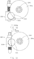
- Fig. 5 to Fig. 12 are illustrations for the damping adjustment device 300 according to one embodiment of the present disclosure.
- the damping adjustment device 300 comprises a damping module 310 and an adjusting module 330, wherein the damping module 310 comprises a first damping unit 312 and a second damping unit 314.
- the adjusting module 330 is connected to the first damping unit 312 and the second damping unit 314 for operating simultaneously with the first damping unit 312 and the second damping unit 314.
- the adjusting module 330 comprises a shifting assembly 332 which comprises a threaded rod 3321 and a nut 3323 coupled to the threaded rod 3321 by threaded engagement.
- a shifting assembly 332 which comprises a threaded rod 3321 and a nut 3323 coupled to the threaded rod 3321 by threaded engagement.
- the second damping unit 314 of the damping module 310 comprises a rotation axis 3141 which the second damping unit 314 rotates about.
- the rotation axis 3141 of the second damping module 314 is substantially perpendicular to the shifting axis 3324 of the shifting assembly.
- the driving device 200 can further comprise a driving axis which is substantially perpendicular to the shifting axis 3324.
- the second damping unit 314, the shifting assembly 332 and the driving device 200 are connected to each other, and thus the damping unit 314 and the shifting assembly 332 operate simultaneously with the driving device 200. Therefore, the shifting assembly 332 moves the first damping unit 312 relative to the second damping unit 314 while the driving device 200 driving the second damping unit 314 to rotate, whereby the interaction force between the first damping unit 312 and the second damping unit 314 is changed.
- the first damping unit 312 is exemplified by a magnetic unit 312a, wherein the magnetic unit 312 can be a magnet or an electromagnet;
- the second damping unit 314 is exemplified by a conductive unit 314a, wherein the conductive unit 314a can be a conductive disk which can generate an electromagnetic induction force with the magnetic unit 312a, such as an aluminum disk or a copper disk.
- the electromagnetic induction force is generated between the magnetic unit 314a and the conductive unit 314a, and the adjusting module 330 alters the relative position of the magnetic unit 312a and the conductive unit 314a for changing the electromagnetic induction force.
- the shape and size of the magnetic unit 312a and the conductive unit 314a are only illustrated as an example and not intended to limit the scope of the present disclosure.
- the first damping unit can be the conductive unit
- the second damping unit can be the magnetic unit.
- the shifting assembly 332 moves the first damping unit 312 relative to the second damping unit 314 in an radial direction of the rotation axis 3141 of the second damping unit 314 for changing the interaction force between the first damping unit 312 and the second damping unit 314.
- the shifting assembly 332 moves the magnetic unit 312a along the shifting axis 3324a towards the rotation axis 3141 of the conductive unit 314a.
- the shifting assembly 332 moves the magnetic unit 312a along the shifting axis 3324a away from the rotation axis 3141 of the conductive unit 314a.
- the electromagnetic induction force between the magnetic unit 312a and the conductive unit 314a is increased due to the linear velocity of the conductive unit 314a relative to the magnetic unit 312a is increased, and thus the damping force outputted by the damping module 310 to the window covering system 10 is increased.
- Fig. 10 and Fig. 11 schematically shows another embodiment of the present disclosure.
- the first damping unit 312 and the second damping unit 314 have an overlapping area in between, wherein the interaction force is generated within the overlapping area between the first damping unit 312 and the second damping unit 314.
- the shifting assembly 332 alters the overlapping area between the first damping unit 312 and the second damping unit 314 for changing the interaction force between the first damping unit 312 and the second damping unit 314.
- the first damping unit 312 can be a magnetic unit 312b; the second damping unit 314 can be the conductive unit 314a. It should be noted that, the shape and size of the magnetic unit 312b and the conductive unit 314a are only illustrated as an example and not intended to limit the scope of the present disclosure.
- the shifting assembly 332 moves the magnetic unit 312b along the shifting axis 3324b.
- the overlapping area 3121, where the electromagnetic induction force is generated, between the conductive unit 314a and the magnetic unit 312b is reduced.
- the electromagnetic induction force generated between the conductive unit 314a and the magnetic unit 312b is reduced.
- the shifting assembly 332 moves the magnetic unit 312b along the shifting axis 3324b.
- the overlapping area 3121, where the electromagnetic induction force is generated, between the conductive unit 314a and the magnetic unit 312b is increased.
- the electromagnetic induction force generated between the conductive unit 314a and the magnetic unit 312b is increased. Therefore, the damping force outputted by the damping module 310 to the window covering system 10 is increased.
- magnetic force damping is only for illustrating the gradual damping effect provided by the damping adjustment device 300 according to one embodiment of the present disclosure and not intended to limit the implementation of the damping adjustment module 300.
- other types of damping can be employed by the damping adjustment device 300 with appropriate and reasonable modification, for example, frictional force damping, oil (fluid resistance) damping, and electrostatic force damping.
- damping modules can also be employed simultaneously in a single damping adjustment device to optimize the damping effect provided by the damping adjustment device for the window covering system.
- the adjusting module 330 operates simultaneously with the first damping unit 312 and the second damping unit 314 of the damping module 310 via a connecting rod 334, wherein the connecting rod 334 comprises a bevel gear 3341, a flat gear 3343 and a rod body 3345.
- the bevel gear 3341 and the flat gear 3343 are fixed separately at two opposite ends of the rod body 3345.
- the shifting assembly 332 comprises a bevel gear 3325 fixed to one end of the threaded rod 3321, wherein the bevel gear 3341 of the connecting rod 334 is coupled to the bevel gear 3325 of the shifting assembly 332 by toothed engagement. Therefore, the connecting rod 334 drives the threaded rod 3321 of the shifting assembly 332 to rotate when the connecting rod 334 rotates. At the same time, the nut 3323 and the first damping unit 312 are moved while the threaded rod 3321 is rotating. Thus, the relative position of the first damping unit 312 and the second damping unit 314 is altered.
- the rod body 3345 of the connecting rod 334 is substantially perpendicular to the threaded rod 3321 of the shifting assembly 332, but is not limited thereto.
- the damping module 310 further comprises a flat gear 202 which is connected to the second damping unit 314 coaxially.
- the flat gear 3343 of the connecting rod 334 is engaged to the flat gear 202 of the damping module 310 for operating simultaneously with the flat gear 202.
- the connecting rod 334 is substantially parallel to the rotation axis 3141 of the second damping unit 314.
- the driving device 200 of the window covering system 10 is connected to the damping adjustment device 300 via the flat gear 202 for simultaneous operation between the driving device 200 and the damping adjustment device 300, wherein the driving device 200 and the second damping unit 314 of the damping module 310 are positioned coaxially.
- the rotation axis of the driving device can be either substantially parallel or perpendicular to the rotation axis of the second damping unit, or the rotation axis of the driving device can be coaxially positioned relative to the connecting rod.
- the window covering system 10 can further comprise an accelerator 370 connected between the driving device 200 and the damping module 310.
- the accelerator 370 is connected between the second damping unit 314 of the damping module 310 and the flat gear 202.
- the accelerator 370 is driven to operate by the driving device 200, and thus the speed of the relative motion between the first damping unit 312 and the second damping unit 314 is greater than the operational speed of the driving device 200.
- the second damping unit 314 is driven by the accelerator 370 to rotate with acceleration for enhancing the interaction force generated between the first damping unit 312 and the second damping unit 314, and thus increasing the damping force outputted by the damping module 310 to the driving device 200.
- the accelerator 370 can be a planetary gear accelerator or any other equivalent accelerating device. It should be noted that, the accelerator 370 is not a necessary configuration to the window covering system 10 if the damping module 310 can output enough damping force to the window covering system 10 without the accelerator 370. In other words, whether to include the accelerator 370 in the window covering system 10 may depend on how much damping force is outputted, and therefore the accelerator 370 is not a necessary component of the window covering system10 in any embodiment of the present disclosure.
- the window covering system 10 further comprising a unidirectional controller 350 which is connected between the driving device 200 and the damping module 310.
- the unidirectional controller 350 can be a roller clutch, spring clutch, track clutch, friction clutch, ratchet clutch or any other equivalent unidirectional clutches.
- the driving device 200 rotates in a second direction D2 which is opposite to the first direction D1, wherein the driving device 200 rotates freely in the second direction D2 independently of the damping module 310 due to the unidirectional controller 350.
- the damping module 310 stops outputting the damping force to the driving device 200 due to the unidirectional controller 350 which restricts the simultaneous operation between the driving device 200 and the damping module 310 while the driving device 200 rotating in the second direction D2. It should be noted that, even though the unidirectional controller 350 restricts the simultaneous operation between the driving device 200 and the damping module 310, the driving device 200 can still operate simultaneously with the adjusting module 330.
- the rotation of the driving device 200 in the second direction D2 drives the adjusting module 330, and thus the shifting assembly 332 moves the first damping module 312 back to a position before the covering material 13 expands.
- the unidirectional controller 350 is only a standard configuration in any embodiment of the present disclosure and not a subject of the present disclosure. Therefore, the unidirectional controller 350 is not to be described any further.
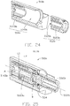
- Fig. 13 to Fig. 15 are schematic illustrations of damping adjustment device 400 according to one embodiment of the present disclosure.
- the damping adjustment device 400 comprises a damping module 410 and an adjusting module 430, wherein the damping module 410 comprises a first damping unit 412 and a second damping unit 414, and the adjusting module 430 is connected to the first damping unit 412 and the second damping unit 414 of the damping module 410 for simultaneously operating with the first damping unit 412 and the second damping unit 414.
- the adjusting module 430 comprises a shifting assembly 432 which comprises a threaded rod 4321 and a nut 4323 coupled to the threaded rod 4321 by threaded engagement.
- a shifting assembly 432 which comprises a threaded rod 4321 and a nut 4323 coupled to the threaded rod 4321 by threaded engagement.
- the threaded rod 4321 rotates, the threaded rod 4321 drives the nut 4323 to move along a rotation axis of the threaded rod 4321 in an axial direction of the rotation axis, and the first damping unit 412 connected to the nut 4323 moves simultaneously with the nut 4323 along a shifting axis 4324, wherein the shifting axis 4324 is substantially parallel to the rotation axis of the threaded rod 4321.
- the first damping unit 412 and the nut 4323 are either integrally formed in one piece or the first damping unit 412 can be fixed to the nut 4323.
- the driving device 200 comprises a driving axis, wherein the driving axis is substantially parallel to the shifting axis 4324 of the shifting assembly 432.
- the second damping unit 414 of the damping module 410 comprises a rotation axis 4141 which the second damping unit 414 rotates about.
- the rotation axis 4141 of the second damping unit 414 is coaxially positioned with the shifting axis 4324 of the shifting assembly 432.
- the shifting assembly 332 moves the first damping unit 412 relative to the second damping unit 414 while the driving device 200 driving the second damping unit 414 to rotate, whereby the interaction force between the first damping unit 412 and the second damping unit 414 is changed. Furthermore, the shifting assembly 432 alters the interaction force between the first damping unit 412 and the second damping unit 414 by moving the first damping unit 412 relative to the second damping unit 414 along the rotation axis 4141 of the second damping unit 414 in an axial direction of the rotation axis 4141.
- the first damping unit 412 is exemplified by a hollow sleeve with an inner wall 4121 which is partially frustoconical;
- the second damping unit 414 is exemplified by an elastic component which can be substantially "S" shape, "Z” shape or any other equivalent elastic components.
- the elastic component comprises the rotation axis 4141, and the elastic component can rotate about the rotation axis 4141.
- a frictional force is generated between the elastic component of the second damping unit 414 and the inner wall 4121 of the first damping unit 412 when the elastic component is rotating and contacting the inner wall 4121.
- first damping unit 412 and the second damping unit 414 are only illustrated as an example and not intended to limit the scope of the present disclosure.
- first damping unit can be the elastic component
- second damping unit can be the hollow sleeve.
- the inner diameter of the inner wall 4121 of the first damping unit 412 increases while the first damping unit 412 is moving away from the second damping unit 414, whereby the "S" shape second damping unit 414 is relaxed by the first damping unit 412 due to the increase in the inner diameter. Therefore, the frictional force between the first damping unit 412 and the second damping unit 414 is reduced, and thus the damping force outputted by the damping module 410 to the window covering system 10 is reduced.
- the inner wall 4121 of the first damping unit 412 varies a radial length of the second damping unit 414 in order to change the frictional force.
- the inner diameter of the inner wall of the first damping unit reduces while the first damping unit is moving away from the second damping unit, whereby the "S" shape second damping unit is compressed by the first damping unit due to the reduction in the inner diameter. Therefore, the frictional force between the first damping unit and the second damping unit is enhanced, and thus the damping force outputted by the damping module to the window covering system is increased.
- the inner diameter of the inner wall of the first damping unit increases while the first damping unit is moving closer to the second damping unit, whereby the "S" shape second damping unit is relaxed by the first damping unit due to the increase in the inner diameter.
- the frictional force between the first damping unit and the second damping unit is reduced, and thus the damping force outputted by the damping module to the window covering system is reduced.
- the inner diameter of the inner wall of the first damping unit can be varied according to the damping force required during the expansion of the covering material, for example, the inner wall of the first damping unit can be defined with a "wave" shape.
- frictional force damping is only for illustrating the gradual damping effect provided by the damping adjustment device 400 according to one embodiment of the present disclosure and not intended to limit the implementation of the damping adjustment module 400.
- other types of damping can be employed by the damping adjustment device 400 with appropriate and reasonable modification, for example, magnetic force damping, oil (fluid resistance) damping, and electrostatic force damping.
- damping modules can also be employed simultaneously in a single damping adjustment device to optimize the damping effect provided by the damping adjustment device for the window covering system.
- the adjusting module 430 operates simultaneously with the damping unit 412 and the damping unit 414 of the damping module 410 via a connecting rod 434, wherein the connecting rod 434 comprises a flat gear 4341, a flat gear 4343 and a rod body 4345.
- the flat gear 4341 and the flat gear 4343 are fixed separately at two opposite ends of the rod body 4345.
- the shifting assembly 432 comprises a flat gear 4325 fixed to one end of the threaded rod 4321.
- the flat gear 4341 of the connecting rod 434 is coupled to the flat gear 4325 of the shifting assembly 432 by toothed engagement. Therefore, the connecting rod 434 drives the threaded rod 4321 of the shifting assembly 432 to rotate when the connecting rod 434 rotates. At the same time, the nut 4323 and the damping unit 412 are moved while the threaded rod 4321 is rotating.
- the rod body 4345 of the connecting rod 434 is substantially parallel to the threaded rod 4321 of the shifting assembly 432, but is not limited thereto.
- the damping module 410 further comprises a flat gear 202 which is connected to the second damping unit 414 coaxially.
- the flat gear 4343 of the connecting rod 434 is engaged to the flat gear 202 of the damping module 410 for operating simultaneously with the flat gear 202.
- the connecting rod 434 is substantially parallel to the rotation axis 4141 of the second damping unit 414.
- the driving device 200 of the window covering system 10 is connected to the damping adjustment device 400 via the flat gear 202 for simultaneous operation between the driving device 200 and the damping adjustment device 400, wherein the driving device 200 and the second damping unit 414 of the damping module 410 are positioned coaxially.
- the window covering system 10 can further comprise an accelerator 370 connected between the driving device 200 and the damping module 410, and the accelerator 370 is configured to simultaneously operate with the driving device 200 and the damping module 410.
- the accelerator 370 is connected between the second damping unit 414 of the damping module 410 and the flat gear 202. Since the accelerator 370 is not a necessary component of the window covering system10 in any embodiment of the present disclosure, and the installation condition, object and effect of the accelerator 370 are described before as well. Therefore, detail of the accelerator 370 will not be described herein.
- the window covering system 10 further comprising a unidirectional controller 350 which is connected between the driving device 200 and the damping module 410.
- the unidirectional controller 350 is only a standard configuration in any embodiment of the present disclosure and not a subject of the present disclosure.
- the installation condition, object and effect of the unidirectional controller 350 are described before as well. Therefore, detail of the unidirectional controller 350 will not be described herein.
- Fig. 16 to Fig. 26 are schematic illustrations of a damping adjustment device 500 according to one embodiment of the present disclosure.
- the damping adjustment device 500 comprises a damping module 510a and an adjusting module 530, wherein the damping module 510a comprises a first damping unit 512a and a second damping unit 514a, and the adjusting module 530 is only connected to the first damping unit 512a of the damping module 510a for simultaneously operating with the first damping unit 512a.
- the adjusting module 530 comprises a shifting assembly 532 which can drive the first damping unit 512a to rotate about the shifting axis 5325 simultaneously.
- the shifting assembly 532 comprises a threaded rod 5321, a threaded bush 5323 and a base 5326, wherein one end of the threaded rod 5321 is sleeved over by the threaded bush 5323 which is fixed on the base 5326.
- An external thread 5322 of the threaded rod 5321 is coupled to an internal thread 5324 of the threaded bush 5323 by threaded engagement.
- the threaded bush 5323 Since the threaded bush 5323 is fixed to the base 5326, the threaded rod 5321 moves along the shifting axis 5325 in an axial direction of the shifting axis 5325 while the threaded rod 5321 is rotating.
- the first damping unit 512a of the damping module 510a is fixed to the other end of the threaded rod 5321, and thus the first damping unit 512a rotates together with the threaded rod 5321.
- the shifting axis 5325, a rotation axis of the threaded rod 5321 and a rotation axis 5122a of the first damping unit 512a are positioned coaxially.
- the shifting axis 5325, the rotation axis of the threaded rod 5321 and the rotation axis 5122a of the first damping unit 512a can be parallel, coaxial or a combination of both.
- the driving device 200 further comprises a driving axis positioned coaxially with the shifting axis 5325 of the shifting assembly 532.
- the shifting assembly 532 drives the first damping unit 512a to rotate about the shifting axis 5325.
- the second damping unit 514a of the damping module 510a is sleeved over the first damping unit 512a which is positioned between the shifting assembly 532 and the second damping unit 514a.
- the shifting assembly 532 is positioned between the second damping unit 514a and the driving device 200.
- the first damping unit 512a is driven by the shifting assembly 532 to move relative to the second damping unit 514a in order to change the interaction force between the first damping unit 512a and the second damping unit 514a.
- the first damping unit 512a is exemplified by an elastic component which comprises an elastic unit 5121a, a friction block 5123a, and a base 5125a, wherein the elastic unit 5121a and the friction block 5123a are connected to each other, and the elastic unit 5121a and the friction block 5123a are both mounted on the base 5125a;
- the second damping unit 514a is exemplified by a hollow sleeve with an inner wall 5141a which is partially frustoconical.
- the elastic component comprises the rotation axis 5122a and the elastic component can rotate about the rotation axis 5122a.
- a frictional force is generated between the elastic component of the first damping unit 512a and the inner wall 5141a of the second damping unit 514a when the elastic component is rotating and contacting the inner wall 5141a.
- the elastic unit 5121a is mounted to the base 5125a by passing through the base 5125a, and both friction blocks 5123a are fixed at opposite ends of the elastic unit 5121a such that the friction blocks 5123a are positioned symmetrically with regard to the elastic unit 5121a.
- the elastic unit 5121a is fixed to the base 5125a, and the other end of the elastic unit 5121a is connected to the friction block 5123a such that the friction block 5123a is positioned unsymmetrically with regard to the elastic unit 5121a.
- the shape and size of the elastic unit 5121a, the friction block 5123a, the base 5125a and the inner wall 5141a of the hollow sleeve are only illustrated as an example and not intended to limit the scope of the present disclosure.
- the first damping unit can be the hollow sleeve
- the second damping unit can be the elastic component.
- the frictional force between the first damping unit 512a and the second damping unit 514a is enhanced, and thus the damping force outputted by the damping module 510a to the window covering system 10 is increased.
- the inner diameter of the inner wall 5141a of the second damping unit 514a increases while the first damping unit 512a is moving away from the second damping unit 514a, whereby the friction blocks 5123a of the first damping unit 512a are relaxed to part from each other by the second damping unit 514a such that a radial length of the elastic component relative to the rotation axis 5122a is increased due to the increase in the inner diameter. Therefore, the frictional force between the first damping unit 512a and the second damping unit 514a is reduced, and thus the damping force outputted by the damping module 510a to the window covering system 10 is reduced.
- the inner diameter of the inner wall of the second damping unit reduces while the first damping unit is moving away from the second damping unit, whereby the friction blocks of the first damping unit are pushed towards each other by the second damping unit such that a radial length of the elastic component relative to the rotation axis is reduced due to the reduction in the inner diameter. Therefore, the frictional force between the first damping unit and the second damping unit is enhanced, and thus the damping force outputted by the damping module to the window covering system is increased.
- the inner diameter of the inner wall of the second damping unit increases while the first damping unit is moving closer to the second damping unit, whereby the friction blocks of the first damping unit are relaxed to part from each other by the second damping unit such that a radial length of the elastic component relative to the rotation axis is increased due to the increase in the inner diameter. Therefore, the frictional force between the first damping unit and the second damping unit is reduced, and thus the damping force outputted by the damping module to the window covering system is reduced.
- the inner diameter of the inner wall of the second damping unit can be varied according to the damping force required during the expansion of the covering material, for example, the inner wall of the second damping unit can be defined with a "wave" shape.
- Fig. 22 to Fig. 26 are schematic illustrations of the damping adjustment device 500 according to another embodiment of the present disclosure.
- the damping adjustment device 500 comprises a damping module 510b and an adjusting module 530, wherein the damping module 510b comprises a first damping unit 512b and a second damping unit 514b, and the adjusting module 530 is only connected to the first damping unit 512b of the damping module 510b for simultaneously operating with the first damping unit 512b.
- the adjusting module 530 comprises the shifting assembly 532.
- the structure and the connection between components of the shifting assembly 532 are described in detail as foregoing in Figs. 16 to 18 , and thus will not be repeated herein.
- the second damping unit 514b of the damping module 510b is sleeved over the first damping unit 512b which is positioned between the shifting assembly 532 and the second damping unit 514b.
- the shifting assembly 532 operates, the first damping unit 512b is driven by the shifting assembly 532 to move relative to the second damping unit 514b in order to change the interaction force between the first damping unit 512b and the second damping unit 514b.
- the first damping unit 512b has a cylindrical appearance, wherein the first damping unit 512b comprises at least one concentric structure 5123b and a space 5121b which is partially divided by the at least one concentric structure 5123b; the second damping unit 514b has an internal structure similar to the first damping unit 512b, wherein the second damping unit 514b comprises at least one concentric structure 5143b and a space 5141b which is partially divided by the at least one concentric structure 5143b.
- an inner diameter of the space 5141b of the second damping unit 514b is larger than an outer diameter of the first damping unit 512b, and thus the first damping unit 512b can be contained within the space 5141b of the second damping unit 514b where the first damping unit 512b can move within.
- the first damping unit 512b is completely or partially contained within the space 5141b of the second damping unit 514b.
- the first damping unit and the second damping unit can comprise other stirring structure within, wherein the stirring structure can stir a fluid to generate fluid resistance, for example, a paddle or a blade.
- the damping adjustment device 500 further comprises a fluid between the first damping unit 512b and the second damping unit 514b, and the interaction force generated between the first damping unit 512b and the second damping unit 514b is a fluid resistance.
- the fluid can comprise liquid or gas, particularly substance with high viscosity such as damping oil.
- the space 5141b of the second damping unit 514b is filled with the fluid. Specifically, the fluid fills an airtight space formed between the second damping unit 514b and the threaded brush 5323.
- the adjusting module 530 further comprises a sealing ring 534 for preventing the fluid to escape from the threaded brush 5323, wherein the sealing ring 534 is sleeved over the threaded rod 5321 and positioned between the threaded rod 5321 and the threaded brush 5323 for enhancing sealing ability of adjusting module 530.
- an overlapping area is defined between the first damping unit 512b and the second damping unit 514b, and the fluid resistance is generated by the first damping unit 512b and the second damping unit 514b within the overlapping area.
- the fluid resistance is generated between the first damping unit 512b, the second damping unit 514b and the fluid.
- the adjusting module 530 alters the relative position of the first damping unit 512b and the second damping unit 514b, and thus the overlapping area between the first damping unit 512b and the second damping unit 514b is altered.
- the second damping unit does not have the channel, but a ventilation hole is defined at top of the space of the second damping unit for air to flow in and out.
- a contacting area between the fluid and the first damping unit changes with respect to the expansion of the covering material, and therefore changes the damping force outputted by the damping module to the driving device.
- frictional force damping and fluid resistance damping are only for illustrating the gradual damping effect provided by the damping adjustment device 500 according to one embodiment of the present disclosure and not intended to limit the implementation of the damping adjustment module 500.
- other types of damping can be employed by the damping adjustment device 500 with appropriate and reasonable modification, for example, magnetic force damping, and electrostatic force damping.
- damping modules can also be employed simultaneously in a single damping adjustment device to optimize the damping effect provided by the damping adjustment device for the window covering system.
- the window covering system 10 can further comprising a unidirectional controller 350 which is connected between the driving device 200 and the damping module 510a or the damping module 510b.
- the unidirectional controller 350 is only a standard configuration in any embodiment of the present disclosure and not a subject of the present disclosure.
- the installation condition, object and effect of the unidirectional controller 350 are described before as well. Therefore, detail of the unidirectional controller 350 will not be described herein.
- the window covering system 10 can further comprise an accelerator (not shown) connected between the driving device 200 and the damping module 510a or the damping module 510b. Since the accelerator is not a necessary component of the window covering system10 in any embodiment of the present disclosure, and the installation condition, object and effect of the accelerator are described before as well. Therefore, detail of the accelerator will not be described herein.
Landscapes
- Engineering & Computer Science (AREA)
- Structural Engineering (AREA)
- Architecture (AREA)
- Civil Engineering (AREA)
- General Engineering & Computer Science (AREA)
- Physics & Mathematics (AREA)
- Mechanical Engineering (AREA)
- Acoustics & Sound (AREA)
- Aviation & Aerospace Engineering (AREA)
- Electromagnetism (AREA)
- Power-Operated Mechanisms For Wings (AREA)
- Operating, Guiding And Securing Of Roll- Type Closing Members (AREA)
- Vibration Prevention Devices (AREA)
- Blinds (AREA)
- Curtains And Furnishings For Windows Or Doors (AREA)
- Fluid-Damping Devices (AREA)
Claims (20)
- Eine Dämpfung-Anpassungsvorrichtung (300, 400, 500) für ein Fenster-Abdeckungssystem (10), wobei das Fenster-Abdeckungssystem (10) ein Abdeckungsmaterial (13) und eine Antriebsvorrichtung (200) aufweist, die von dem Abdeckungsmaterial (13) angetrieben wird, während sich das Abdeckungsmaterial (13) ausdehnt oder zusammenzieht; wobei die Dämpfung-Anpassungsvorrichtung (300, 400, 500) aufweist:ein Dämpfungsmodul (310, 410, 510a, 510b), welches eine erste Dämpfungseinheit (312, 412, 512a, 512b) und eine zweite Dämpfungseinheit (314, 414, 514a, 514b) aufweist, und eine Dämpfungskraft, die von dem Dämpfungsmodul (310, 410, 510a, 510b) an das Fenster-Abdeckungssystem (10) ausgegeben werden kann, wenn die erste Dämpfungseinheit und die zweite Dämpfungseinheit (314, 414, 514a, 514b) eine Wechselwirkungskraft dazwischen erzeugen durch eine relative Bewegung zwischen der ersten Dämpfungseinheit (312, 412, 512a, 512b) und der zweiten Dämpfungseinheit (314, 414, 514a, 514b); undein Anpassungsmodul (330, 430, 530), das mit dem Dämpfungsmodul (310, 410, 510a, 510b) verbunden ist, um simultan mit dem Dämpfungsmodul (310, 410, 510a, 510b) betrieben zu werden, wobei die Dämpfungskraft von dem Dämpfungsmodul (310, 410, 510a, 510b) dadurch angepasst wird, dass das Anpassungsmodul (330, 430, 530) eine relative Position der ersten Dämpfungseinheit (312, 412, 512a, 512b) und der zweiten Dämpfungseinheit (314, 414, 514a, 514b) verändert, wenn die relative Bewegung zwischen der ersten Dämpfungseinheit (312, 412, 512a, 512b) und der zweiten Dämpfungseinheit (314, 414, 514a, 514b) stattfindet; wobei die Dämpfung-Anpassungsvorrichtung (300, 400, 500) dadurch gekennzeichnet ist, dass:
das Dämpfungsmodul (310, 410, 510a, 510b) gestaltet ist, um von der Antriebsvorrichtung (200) angetrieben zu werden, um die Dämpfungskraft an die Antriebsvorrichtung (200) auszugeben, wenn sich das Abdeckungsmaterial (13) ausdehnt, wobei das Anpassungsmodul (330, 430, 530) die Wechselwirkungskraft zwischen der ersten Dämpfungseinheit (312, 412, 512a, 512b) und der zweiten Dämpfungseinheit (314, 414, 514a, 514b) erhöht, um die Dämpfungskraft von dem Dämpfungsmodul (310, 410, 510a, 510b) zu vergrößern, wenn die Antriebsvorrichtung (200) betrieben wird. - Die Dämpfung-Anpassungsvorrichtung (300, 400, 500) gemäß Anspruch 1, wobei das Anpassungsmodul (330, 430, 530) eine Verschiebe-Vorrichtung (332, 432, 532) aufweist, die mit der ersten Dämpfungseinheit (312, 412, 512a, 512b) verbunden ist, um die erste Dämpfungseinheit (312, 412, 512a, 512b) zu bewegen, um die relative Position der ersten Dämpfungseinheit (312, 412, 512a, 512b) und der zweiten Dämpfungseinheit (314, 414, 514a, 514b) zu verändern.
- Die Dämpfung-Anpassungsvorrichtung (300, 400, 500) gemäß Anspruch 2, wobei die Verschiebe-Vorrichtung (332, 432, 532) gestaltet ist, um die erste Dämpfungseinheit (312, 412, 512a, 512b) entlang einer Verschiebe-Achse (3324, 3324a, 3324b, 4324, 5325) der Verschiebe-Vorrichtung (332, 432, 532) in einer Axialrichtung der Verschiebe-Achse (3324, 3324a, 3324b, 4324, 5325) zu bewegen, um die relative Position der ersten Dämpfungseinheit (312, 412, 512a, 512b) und der zweiten Dämpfungseinheit (314, 414, 514a, 514b) zu verändern, um die Wechselwirkungskraft zwischen der ersten Dämpfungseinheit (312, 412, 512a, 512b) und der zweiten Dämpfungseinheit (314, 414, 514a, 514b) zu ändern.
- Die Dämpfung-Anpassungsvorrichtung (500) gemäß Anspruch 3, wobei die erste Dämpfungseinheit (512a, 512b) koaxial mit der Verschiebe-Vorrichtung (532) positioniert ist, wobei die Verschiebe-Vorrichtung (532) gestaltet ist, um zu rotieren und die erste Dämpfungseinheit (512a, 512b) anzutreiben, sodass sie simultan um die Verschiebe-Achse (5325) rotiert.
- Die Dämpfung-Anpassungsvorrichtung (500) gemäß Anspruch 4, wobei die erste Dämpfungseinheit (512a, 512b) zwischen der Verschiebe-Vorrichtung (532) und der zweiten Dämpfungseinheit (514a, 514b) positioniert ist.
- Die Dämpfung-Anpassungsvorrichtung (400) gemäß Anspruch 3, wobei die zweite Dämpfungseinheit (414) eine Rotationsachse (4141) aufweist, die koaxial zu der Verschiebe-Achse (4324) ist, wobei die zweite Dämpfungseinheit (414) gestaltet ist, um simultan mit der Verschiebe-Vorrichtung (432) betrieben zu werden, wobei sich die Wechselwirkungskraft zwischen der ersten Dämpfungseinheit (412) und der zweiten Dämpfungseinheit (414) ändert, wenn die Verschiebe-Vorrichtung (432) die erste Dämpfungseinheit (412) relativ zu der zweiten Dämpfungseinheit (414) in einer Axialrichtung der Rotationsachse (4141) bewegt und wenn die zweite Dämpfungseinheit (414) um die Rotationsachse (4141) rotiert.
- Die Dämpfung-Anpassungsvorrichtung (300) gemäß Anspruch 3, wobei die zweite Dämpfungseinheit (314) eine Rotationsachse (3141) aufweist, die im Wesentlichen rechtwinklig zu der Verschiebe-Achse (3324, 3324a) ist, und die zweite Dämpfungseinheit (314) gestaltet ist, um simultan mit der Verschiebe-Vorrichtung (332) betrieben zu werden, wobei die Verschiebe-Vorrichtung (332) gestaltet ist, um die erste Dämpfungseinheit (312) relativ zu der zweiten Dämpfungseinheit (314) in einer radialen Richtung der Rotationsachse (3141) zu bewegen, während die zweite Dämpfungseinheit (314) um die Rotationsachse (3141) rotiert, wodurch sich die Wechselwirkungskraft zwischen der ersten Dämpfungseinheit (312) und der zweiten Dämpfungseinheit (314) ändert.
- Die Dämpfung-Anpassungsvorrichtung (300) gemäß Anspruch 3, wobei die Wechselwirkungskraft von der ersten Dämpfungseinheit (312) und der zweiten Dämpfungseinheit (314) innerhalb eines überlappenden Bereichs zwischen der ersten Dämpfungseinheit (312) und der zweiten Dämpfungseinheit (314) erzeugt wird, wobei die zweite Dämpfungseinheit (314) eine Rotationsachse (3141) aufweist, die im Wesentlichen rechtwinklig zu der Verschiebe-Achse (3324b) ist, und die zweite Dämpfungseinheit (314) mit der Verschiebe-Vorrichtung (332) verbunden ist, um simultan mit der Verschiebe-Vorrichtung (332) betrieben zu werden, wobei sich die Wechselwirkungskraft zwischen der ersten Dämpfungseinheit (312) und der zweiten Dämpfungseinheit (314) ändert, wenn die zweite Dämpfungseinheit (314) um die Rotationsachse (3141) rotiert und die Verschiebe-Vorrichtung (332) den überlappenden Bereich verändert.
- Die Dämpfung-Anpassungsvorrichtung (300, 400) gemäß Anspruch 2, wobei das Anpassungsmodul (330, 430) ferner einen Verbindungsstab (334, 434) mit zwei Enden aufweist, wobei die Verschiebe-Vorrichtung (332, 432) mit einem Ende verbunden ist und die zweite Dämpfungseinheit (314, 414) mit dem anderen Ende verbunden ist, wodurch die Verschiebe-Vorrichtung (332, 432) und die zweite Dämpfungseinheit (314, 414) gestaltet sind, um zum Ändern der relativen Position der ersten Dämpfungseinheit (312, 412) und der zweiten Dämpfungseinheit (314, 414) simultan betrieben zu werden.
- Die Dämpfung-Anpassungsvorrichtung (300, 400, 500) gemäß Anspruch 3, wobei die Verschiebe-Vorrichtung (332, 432, 532) ferner einen Gewindestab (3321, 4321, 5321) aufweist, der parallel oder koaxial zu der Verschiebe-Achse (3324, 3324a, 3324b, 4324, 5325) ist, wobei der Gewindestab (3321, 4321, 5321) mit der ersten Dämpfungseinheit (312, 412, 512a, 512b) verbunden ist und gestaltet ist, um die erste Dämpfungseinheit (312, 412, 512a, 512b) anzutreiben, sodass sie sich entlang der Verschiebe-Achse (3324, 3324a, 3324b, 4324, 5325) in einer Axialrichtung der Verschiebe-Achse (3324, 3324a, 3324b, 4324, 5325) bewegt, wodurch die relative Position der ersten Dämpfungseinheit (312, 412, 512a, 512b) und der zweiten Dämpfungseinheit (314, 414, 514a, 514b) durch die Verschiebe-Vorrichtung (332, 432, 532) geändert wird, um die Wechselwirkungskraft zwischen der ersten Dämpfungseinheit (312, 412, 512a, 512b) und der zweiten Dämpfungseinheit (314, 414, 514a, 514b) zu ändern.
- Die Dämpfung-Anpassungsvorrichtung (300) gemäß Anspruch 1, wobei eine von der ersten Dämpfungseinheit (312) und der zweiten Dämpfungseinheit (314) eine magnetische Einheit (312a, 312b) aufweist, und die andere von der ersten Dämpfungseinheit (312, 412, 512a, 512b) und der zweiten Dämpfungseinheit (314, 414, 514a, 514b) eine leitende Einheit (314a) aufweist, wobei die Wechselwirkungskraft eine elektromagnetische Induktionskraft ist, welche zwischen der magnetischen Einheit (312a, 312b) und der leitenden Einheit (314a) erzeugt wird, wenn dazwischen die relative Bewegung stattfindet, wobei die elektromagnetische Induktionskraft geändert wird, wenn die relative Position der magnetischen Einheit (312a, 312b) und der leitenden Einheit (314a) durch das Anpassungsmodul (330, 430, 530) geändert wird.
- Die Dämpfung-Anpassungsvorrichtung (400, 500) gemäß Anspruch 1, wobei die Wechselwirkungskraft eine Reibungskraft ist, welche durch die relative Bewegung zwischen der ersten Dämpfungseinheit (412, 512a) und der zweiten Dämpfungseinheit (414, 514a) erzeugt wird, wenn die erste Dämpfungseinheit (412, 512a) und die zweite Dämpfungseinheit (414, 514a) miteinander in Kontakt sind, wobei sich die Reibungskraft ändert, wenn die relative Position der ersten Dämpfungseinheit (412, 512a) und der zweiten Dämpfungseinheit (414, 514a) von dem Anpassungsmodul (430, 530) geändert wird.
- Die Dämpfung-Anpassungsvorrichtung (400, 500) gemäß Anspruch 12, wobei eine von der ersten Dämpfungseinheit (412, 512a) und der zweiten Dämpfungseinheit (414, 514a) eine elastische Komponente aufweist, welche eine Rotationsachse (4141, 5122a) aufweist, und die andere von der ersten Dämpfungseinheit (412, 512a) und der zweiten Dämpfungseinheit (414, 514a) eine Innenwand aufweist, welche teilweise kegelstumpfförmig ist, wobei die elastische Komponente in Kontakt mit der Innenwand ist, wobei die Reibungskraft zwischen der elastischen Komponente und der Innenwand dadurch erzeugt wird, dass die elastische Komponente um die Rotationsachse (4141, 5122a) der elastischen Komponente rotiert, wobei sich die Reibungskraft ändert, wenn eine radiale Länge der elastischen Komponente durch die Innenwand variiert wird, wenn die relative Position der elastischen Komponente und der Innenwand durch das Anpassungsmodul (330, 430, 530) geändert wird.
- Die Dämpfung-Anpassungsvorrichtung (500) gemäß Anspruch 13, wobei die elastische Komponente eine elastische Einheit (5121a) und einen Reibblock (5123a), der mit der elastischen Einheit (5121a) verbunden ist, aufweist, wobei der Reibblock (5123a) in Kontakt mit der Innenwand ist, wodurch die Reibungskraft zwischen dem Reibblock (5123a) und der Innenwand während des Rotierens der elastischen Komponente erzeugt wird.
- Die Dämpfung-Anpassungsvorrichtung (500) gemäß Anspruch 1, wobei das Dämpfungsmodul (510b) ferner ein Fluid zwischen der ersten Dämpfungseinheit (512b) und der zweiten Dämpfungseinheit (514b) aufweist, wobei die Wechselwirkungskraft, die ein Fluidwiderstand ist, durch die relative Bewegung zwischen der ersten Dämpfungseinheit (512b) und der zweiten Dämpfungseinheit (514b) innerhalb eines überlappenden Bereichs zwischen der ersten Dämpfungseinheit (512b) und der zweiten Dämpfungseinheit (514b) erzeugt wird, wobei sich der Fluidwiderstand ändert, wenn das Anpassungsmodul (530) die relative Position zwischen der ersten Dämpfungseinheit (512b) und der zweiten Dämpfungseinheit (514b) ändert und den überlappenden Bereich zwischen der ersten Dämpfungseinheit (512b) und der zweiten Dämpfungseinheit (514b) ändert.
- Die Dämpfung-Anpassungsvorrichtung (300, 400, 500) gemäß Anspruch 1, wobei die Dämpfung-Anpassungsvorrichtung (300, 400, 500) mit der Antriebsvorrichtung (200) verbunden ist und das Dämpfungsmodul (310, 410, 510a, 510b) gestaltet ist, um die Dämpfungskraft an die Antriebsvorrichtung (200) auszugeben, wobei die erste Dämpfungseinheit (312, 412, 512a, 512b) und die zweite Dämpfungseinheit (314, 414, 514a, 514b) des Dämpfungsmoduls (310, 410, 510a, 510b) gestaltet sind, um die Wechselwirkungskraft dazwischen durch eine relative Bewegung zwischen der ersten Dämpfungseinheit (312, 412, 512a, 512b) und der zweiten Dämpfungseinheit (314, 414, 514a, 514b) zu erzeugen, während die Antriebsvorrichtung (200) durch ein Sich-Ausdehnen des Abdeckungsmaterials (13) angetrieben wird;
das Anpassungsmodul (330, 430, 530) mit dem Dämpfungsmodul (310, 410, 510a, 510b) und der Antriebsvorrichtung (200) verbunden ist, wobei das Anpassungsmodul (330, 430, 530) gestaltet ist, um simultan mit dem Dämpfungsmodul (310, 410, 510a, 510b) betrieben zu werden, um die Dämpfungskraft an die Antriebsvorrichtung (200) anzupassen. - Die Dämpfung-Anpassungsvorrichtung (300, 400, 500) gemäß Anspruch 16, wobei die Antriebsvorrichtung (200) eine Antriebsachse aufweist, welche auf eine aus den Folgenden ausgewählte Art angeordnet ist: im Wesentlichen rechtwinklig zu der Verschiebe-Achse (3324, 3324a, 3324b, 4324, 5325) der Verschiebe-Vorrichtung (332, 432, 532), im Wesentlichen parallel zu der Verschiebe-Achse (3324, 3324a, 3324b, 4324, 5325) der Verschiebe-Vorrichtung (332, 432, 532) oder koaxial zu der Verschiebe-Achse (3324, 3324a, 3324b, 4324, 5325) der Verschiebe-Vorrichtung (332, 432, 532).
- Die Dämpfung-Anpassungsvorrichtung (300, 400, 500) gemäß Anspruch 16, ferner aufweisend:eine unidirektionale Steuereinheit (350), welche zwischen der Antriebsvorrichtung (200) und dem Dämpfungsmodul (310, 410, 510a, 510b) verbunden ist, wobei die unidirektionale Steuereinheit (350) von der Antriebsvorrichtung (200) angetrieben wird, um in einer ersten Richtung zu rotieren, wenn sich das Abdeckungsmaterial (13) ausdehnt, wobei die unidirektionale Steuereinheit (350) gestaltet ist, um die relative Bewegung zwischen der ersten Dämpfungseinheit (312, 412, 512a, 512b) und der zweiten Dämpfungseinheit (314, 414, 514a, 514b) des Dämpfungsmoduls (310, 410, 510a, 510b), welche die Dämpfungskraft an die Antriebsvorrichtung (200) ausgibt, anzutreiben;wobei die Antriebsvorrichtung (200) in einer zweiten Richtung, die entgegengesetzt zu der ersten Richtung ist, rotiert, wenn sich das Abdeckungsmaterial (13) zusammenzieht, wobei die Antriebsvorrichtung (200) aufgrund der unidirektionalen Steuereinheit (350) unabhängig von dem Dämpfungsmodul (310, 410, 510a, 510b) frei in der zweiten Richtung rotiert.
- Die Dämpfung-Anpassungsvorrichtung (300, 400, 500) gemäß Anspruch 16, ferner aufweisend:
einen Beschleuniger (370), welcher zwischen der Antriebsvorrichtung (200) und dem Dämpfungsmodul (310, 410, 510a, 510b) verbunden ist, wobei die Geschwindigkeit der relativen Bewegung größer ist als die Geschwindigkeit der Antriebsvorrichtung (200), wenn das Dämpfungsmodul (310, 410, 510a, 510b) über den Beschleuniger (370) von der Antriebsvorrichtung (200) angetrieben wird. - Die Dämpfung-Anpassungsvorrichtung (300, 400, 500) gemäß Anspruch 16, ferner aufweisend:eine Kopfschiene (11), eine untere Schiene (12) und ein Anheben-Seil (14), wobei das Abdeckungsmaterial (13) zwischen der Kopfschiene (11) und der unteren Schiene (12) positioniert ist, wobei ein Ende des Anheben-Seils (14) mit der unteren Schiene (12) verbunden ist und das andere Ende des Anheben-Seils (14) mit der Antriebsvorrichtung (200) durch das Abdeckungsmaterial (13) hindurch verbunden ist;wobei das Anpassungsmodul (330, 430, 530) die Wechselwirkungskraft zwischen der ersten Dämpfungseinheit (312, 412, 512a, 512b) und der zweiten Dämpfungseinheit (314, 414, 514a, 514b) reduziert, um die Dämpfungskraft von dem Dämpfungsmodul (310, 410, 510a, 510b) zu reduzieren, wenn die Antriebsvorrichtung (200) betrieben wird.
Applications Claiming Priority (4)
| Application Number | Priority Date | Filing Date | Title |
|---|---|---|---|
| CN201620065142.0U CN205605050U (zh) | 2016-01-22 | 2016-01-22 | 窗帘的阻尼装置 |
| US201662318771P | 2016-04-06 | 2016-04-06 | |
| US201662326020P | 2016-04-22 | 2016-04-22 | |
| US201662342289P | 2016-05-27 | 2016-05-27 |
Publications (2)
| Publication Number | Publication Date |
|---|---|
| EP3196398A1 EP3196398A1 (de) | 2017-07-26 |
| EP3196398B1 true EP3196398B1 (de) | 2019-03-27 |
Family
ID=56961182
Family Applications (2)
| Application Number | Title | Priority Date | Filing Date |
|---|---|---|---|
| EP17151668.5A Not-in-force EP3196397B1 (de) | 2016-01-22 | 2017-01-16 | Fensterabdeckungssystem und fensterabdeckungssteuerungsvorrichtung davon |
| EP17151812.9A Active EP3196398B1 (de) | 2016-01-22 | 2017-01-17 | System und vorrichtung für fensterabdeckungssystem |
Family Applications Before (1)
| Application Number | Title | Priority Date | Filing Date |
|---|---|---|---|
| EP17151668.5A Not-in-force EP3196397B1 (de) | 2016-01-22 | 2017-01-16 | Fensterabdeckungssystem und fensterabdeckungssteuerungsvorrichtung davon |
Country Status (6)
| Country | Link |
|---|---|
| US (5) | US10612621B2 (de) |
| EP (2) | EP3196397B1 (de) |
| JP (2) | JP6375395B2 (de) |
| CN (1) | CN205605050U (de) |
| AU (2) | AU2017200377B2 (de) |
| CA (3) | CA2955041C (de) |
Families Citing this family (24)
| Publication number | Priority date | Publication date | Assignee | Title |
|---|---|---|---|---|
| US9810020B2 (en) | 2011-03-11 | 2017-11-07 | Lutron Electronics Co., Inc. | Motorized window treatment |
| US10655386B2 (en) * | 2011-03-11 | 2020-05-19 | Lutron Technology Company Llc | Motorized window treatment |
| WO2014163602A2 (en) | 2013-03-11 | 2014-10-09 | Hunter Douglas Inc. | Operating system for a covering for an architectural opening |
| US10641037B2 (en) * | 2016-01-12 | 2020-05-05 | Hunter Douglas Inc. | Cord drive assembly for an architectural covering with a braking member and associated biasing element |
| CN205605050U (zh) * | 2016-01-22 | 2016-09-28 | 亿丰综合工业股份有限公司 | 窗帘的阻尼装置 |
| CN205532187U (zh) * | 2016-01-29 | 2016-08-31 | 亿丰综合工业股份有限公司 | 窗帘升降控制结构 |
| TWI577870B (zh) * | 2016-03-03 | 2017-04-11 | Chen Jin-Fu | No rope curtain curtain curtain body transmission mechanism |
| CN107269203B (zh) * | 2016-04-06 | 2019-05-17 | 亿丰综合工业股份有限公司 | 窗帘控制机构及其窗帘系统 |
| US10655384B2 (en) * | 2016-10-19 | 2020-05-19 | Hunter Douglas, Inc. | Dual mode architectural structure covering |
| KR102016785B1 (ko) * | 2017-05-16 | 2019-08-30 | 유순기 | 비상계단용 유성기어 증속기를 가진 점성유체 댐퍼 |
| PL3434857T3 (pl) * | 2017-07-25 | 2020-06-15 | Coulisse B.V. | Zasłona z górną szyną, dolną szyną i środkową szyną i pierwszy kontrolny zespół dla środkowej szyny i drugi kontrolny zespół dla dolnej szyny |
| CN207553934U (zh) * | 2017-10-19 | 2018-06-29 | 亿丰综合工业股份有限公司 | 窗帘 |
| US10781635B2 (en) * | 2018-06-11 | 2020-09-22 | Chen Tian Co., Ltd. | Fast positioning structure of safe position limiting device of roller blind |
| US10968072B1 (en) * | 2018-09-25 | 2021-04-06 | The United States Of America As Represented By The Secretary Of The Navy | Automatic diving tending system |
| CN109989336B (zh) * | 2019-04-26 | 2020-10-09 | 重庆大学 | 一种运用磁悬浮技术进行隔振的抗风减震桥梁吊杆 |
| CA3150652A1 (en) * | 2019-07-11 | 2021-01-14 | Maxxmar Inc. | Safety reciprocating wand |
| TWI709685B (zh) * | 2019-08-22 | 2020-11-11 | 程田有限公司 | 窗簾控制器 |
| CN110576725B (zh) * | 2019-09-25 | 2024-09-17 | 董克思 | 一种汽车遮阳帘 |
| CN110712499B (zh) * | 2019-09-25 | 2025-03-07 | 董克思 | 一种磁性减速结构及遮阳帘 |
| CN214330476U (zh) * | 2020-11-25 | 2021-10-01 | 无锡万斯家居科技股份有限公司 | 一种无拉绳窗帘结构 |
| CN215255963U (zh) * | 2021-03-31 | 2021-12-21 | 宁波森瑞机电技术有限公司 | 一种用于电动窗帘的驱动装置及电动窗帘 |
| CN215974326U (zh) * | 2021-06-25 | 2022-03-08 | 东莞市雷富溢窗饰科技有限公司 | 窗帘绕线装置 |
| CN216517735U (zh) * | 2021-11-04 | 2022-05-13 | 亿丰综合工业股份有限公司 | 收线装置及包含其的窗帘 |
| CN116816250B (zh) * | 2023-06-16 | 2025-11-28 | 安吉福浪莱工艺品有限公司 | 一种无拉绳窗帘的阻力调节装置 |
Family Cites Families (171)
| Publication number | Priority date | Publication date | Assignee | Title |
|---|---|---|---|---|
| US3965960A (en) * | 1974-09-16 | 1976-06-29 | Massey Peyton L | Retractable shower shade with adjustable extensibility |
| DE3037725A1 (de) * | 1980-10-06 | 1982-07-22 | Emil Schenker AG, 5012 Schönenwerd | Rafflamellenstore |
| US4466475A (en) * | 1981-11-16 | 1984-08-21 | Kabushiki Kaisha Nichibei | Device for driving and stopping a roll blind |
| JPS58143086A (ja) * | 1982-02-19 | 1983-08-25 | ト−ソ−株式会社 | ロ−ルブラインドのクラツチ装置 |
| JPS58165188U (ja) * | 1982-04-30 | 1983-11-02 | ト−ソ−株式会社 | ロ−ルブラインドの減速装置 |
| US4429729A (en) * | 1982-07-09 | 1984-02-07 | Clopay Corporation | Window shade clutch assembly |
| US4427050A (en) * | 1982-07-26 | 1984-01-24 | Clopay Corporation | Window shade clutch assembly |
| US4754182A (en) * | 1982-09-28 | 1988-06-28 | Streeter Edward C | Link suspension for a rotor member |
| US4797591A (en) * | 1982-09-28 | 1989-01-10 | Streeter Edward C | Link suspension for a rotor member |
| US4523620A (en) * | 1983-01-17 | 1985-06-18 | Clopay Corporation | Window shade clutch assembly |
| US4681279A (en) * | 1985-06-03 | 1987-07-21 | Sm Industrial Co., Ltd | Screen roll means |
| US4684911A (en) * | 1985-09-16 | 1987-08-04 | Streeter Edward C | Wide angle control of permanent magnet rotors |
| IT208635Z2 (it) * | 1986-12-17 | 1988-05-28 | Mottura Spa | Tenda a rullo con freno a masse centrifughe disposto all esterno del rullo e sopporto d estremita includente tale freno |
| DE69125238T2 (de) | 1990-10-11 | 1997-07-17 | Toso Co | Jalousieaufzieh- und Wendemechanismus |
| JP2656147B2 (ja) * | 1990-10-13 | 1997-09-24 | 立川ブラインド工業株式会社 | ロールブラインドのスクリーン昇降装置 |
| JP2631915B2 (ja) | 1990-12-28 | 1997-07-16 | ワイケイケイアーキテクチュラルプロダクツ株式会社 | サッシ内蔵ブラインドの昇降装置 |
| JP2693660B2 (ja) | 1991-07-11 | 1997-12-24 | 立川ブラインド工業株式会社 | 採光調節装置の障害物検知停止装置 |
| US5467266A (en) * | 1991-09-03 | 1995-11-14 | Lutron Electronics Co., Inc. | Motor-operated window cover |
| JPH05214882A (ja) * | 1992-02-06 | 1993-08-24 | Nippon Sheet Glass Co Ltd | 回転操作機構 |
| JPH0726600U (ja) | 1993-10-26 | 1995-05-19 | 三和シヤッター工業株式会社 | シャッタ−等の調速装置 |
| US5437324A (en) * | 1994-01-19 | 1995-08-01 | Newell Operating Company | Shade with variable load braking and lift assist |
| US6496991B1 (en) * | 1995-09-13 | 2002-12-24 | Ergodyne Corporation | Device for patient pullup, rollover, and transfer and methods therefor |
| US5718274A (en) * | 1996-08-01 | 1998-02-17 | Streeter; Edward C. | Adjustable screen having magnetically stabilized louvers |
| US5762281A (en) * | 1997-02-18 | 1998-06-09 | Foley; Michael | Automatically loading cord winder apparatus and method |
| JP2001517107A (ja) * | 1997-04-08 | 2001-10-02 | アーゴダイン・コーポレーション | 患者搬送システム |
| JP3036739B2 (ja) | 1997-04-28 | 2000-04-24 | 株式会社ニフコ | ブラインドのルーバー下降方法 |
| WO1999004126A1 (en) * | 1997-07-16 | 1999-01-28 | A/S Chr. Fabers Fabriker | Winding mechanism for roller blinds |
| AU782302B2 (en) | 1997-07-16 | 2005-07-14 | A/S Chr. Fabers Fabriker | Winding mechanism for roller blinds |
| WO1999023343A1 (en) * | 1997-11-04 | 1999-05-14 | Toti Andrew J | Flat spring drive system and window cover |
| US6129131A (en) | 1997-11-26 | 2000-10-10 | Hunter Douglas Inc. | Control system for coverings for architectural openings |
| JP3524738B2 (ja) * | 1997-11-27 | 2004-05-10 | 株式会社ニチベイ | ロールスクリーン |
| ATE338193T1 (de) * | 1997-12-12 | 2006-09-15 | Hunter Douglas Ind Bv | Vorrichtung zum aufwickeln einer abdeckung |
| US6168107B1 (en) * | 1998-08-27 | 2001-01-02 | Celesco Transducer Products, Inc. | Restraining means for limiting speeds of a measuring cable returning to a linear transducer which is a cable extension transducer |
| JP3378813B2 (ja) | 1998-11-10 | 2003-02-17 | 立川ブラインド工業株式会社 | 日射遮蔽装置の遮蔽材昇降装置及び横型ブラインドのスラット駆動装置 |
| JP3442670B2 (ja) | 1998-11-10 | 2003-09-02 | 立川ブラインド工業株式会社 | 横型ブラインドのスラット駆動装置 |
| JP3261106B2 (ja) | 1998-12-18 | 2002-02-25 | 立川ブラインド工業株式会社 | 横型ブラインドのスラット角度調節装置 |
| JP3485164B2 (ja) | 1999-02-02 | 2004-01-13 | 立川ブラインド工業株式会社 | ブラインド装置 |
| JP2000220369A (ja) | 1999-02-02 | 2000-08-08 | Tachikawa Blind Mfg Co Ltd | ブラインド装置 |
| US6536503B1 (en) * | 1999-03-23 | 2003-03-25 | Hunter Douglas Inc. | Modular transport system for coverings for architectural openings |
| JP2001008407A (ja) | 1999-04-22 | 2001-01-12 | Japan Servo Co Ltd | 駆動電動機 |
| IT1307404B1 (it) | 1999-10-13 | 2001-11-06 | Finvetro Srl | Gruppo di azionamento per tende a veneziana o simili all'interno divetrocamere |
| JP4074420B2 (ja) | 2000-03-27 | 2008-04-09 | 株式会社ニチベイ | ブラインド |
| JP2001317279A (ja) | 2000-05-10 | 2001-11-16 | Viscodrive Japan Ltd | 昇降装置 |
| US7228797B1 (en) * | 2000-11-28 | 2007-06-12 | Sundberg-Ferar, Inc. | Cordless blind |
| US6644375B2 (en) | 2001-01-09 | 2003-11-11 | Newell Window Furnishings | Cordless blind brake |
| JP2002242558A (ja) * | 2001-02-20 | 2002-08-28 | Yokota Riyouhan Kk | 弾性部材 |
| JP2002249264A (ja) * | 2001-02-22 | 2002-09-03 | Piolax Inc | シート状体の巻取装置 |
| ITBO20010396A1 (it) | 2001-06-21 | 2002-12-21 | Carl Emil Felix Minder | Dispositivo di frizione per tende avvolgibili e simili |
| US7025107B2 (en) * | 2001-07-31 | 2006-04-11 | Newell Window Furnishings, Inc. | One-way tensioning mechanism for cordless blind |
| ITPD20010066U1 (it) * | 2001-08-01 | 2003-02-01 | Finvetro Spa | Gruppo di azionamento per tende a veneziana o simili all'interno di vetrocamere |
| US7000668B2 (en) * | 2001-08-27 | 2006-02-21 | Smoke Guard Corporation | System and method for sealing openings in response to smoke, noxious fumes, or contaminated air using a roll-down barrier |
| ITTO20020038A1 (it) * | 2002-01-14 | 2002-04-15 | Gianus Spa | Dispositivo di frenatura viscosa dotato di meccanismo monosenso,in particolare per zanzariere. |
| US6924615B2 (en) * | 2002-02-01 | 2005-08-02 | Somfy Sas | Magnetic encoder for powered window covering |
| WO2003080980A2 (en) * | 2002-03-20 | 2003-10-02 | Rollease Inc. | Semi-cordless unbalanced spring driven blind system and methods for adjusting and making same |
| EP1550787B1 (de) * | 2002-10-07 | 2011-07-13 | Seiki Juko Co., Ltd. | Abschirmvorrichtung mit automatischer aufwicklung |
| TW567811U (en) | 2002-12-04 | 2003-12-21 | Nien Made Entpr Co Ltd | Curtain scroll stopper |
| US7234503B2 (en) * | 2002-12-04 | 2007-06-26 | Jae-Suk Kwak | Roll screen for reduction device |
| US7578334B2 (en) | 2005-06-03 | 2009-08-25 | Hunter Douglas Inc. | Control system for architectural coverings with reversible drive and single operating element |
| US7259485B2 (en) * | 2003-05-23 | 2007-08-21 | Somfy Sas | Magnetic brake for window covering powered by DC motor |
| US20050087394A1 (en) * | 2003-10-23 | 2005-04-28 | Toti Andrew J. | Control rod mechanism and system |
| TWI260363B (en) | 2003-12-09 | 2006-08-21 | Nien Made Entpr Co Ltd | Window shades control mechanism and control method thereof |
| TWM259558U (en) | 2004-07-23 | 2005-03-21 | Ching Feng Home Fashions Co | Cord guiding structure of curtain |
| US7331370B1 (en) * | 2004-08-03 | 2008-02-19 | Shades Unlimited, Inc. | Progressive resistance lifting mechanism for a window covering |
| TWI246415B (en) | 2005-01-06 | 2006-01-01 | Chi-Feng Wu | Ascending and descending device of window curtains |
| US7461683B2 (en) * | 2005-02-28 | 2008-12-09 | Wen-Jen Wang | Curtain rolling buffer apparatus |
| TWI291514B (en) * | 2005-06-14 | 2007-12-21 | Beautiful Window Entpr Co Ltd | Venetian blind cord roll-up device with brake unit and Venetian blind equipped with the cord roll-up device |
| WO2007005560A2 (en) * | 2005-06-30 | 2007-01-11 | Magnetar Technologies Corp. | Axial rotary eddy current brake with adjustable braking force |
| DE102005033275B4 (de) * | 2005-07-15 | 2009-09-10 | Webasto Ag | Wickelwelle für eine Rollovorrichtung |
| TWM289318U (en) * | 2005-11-02 | 2006-04-11 | Ching Feng Home Fashions Co | Retracting-control curtain body structure of window curtain |
| US7543623B2 (en) * | 2005-12-02 | 2009-06-09 | Odl, Incorporated | Insulated glass window shade |
| US20070151676A1 (en) * | 2006-01-04 | 2007-07-05 | Henry Lin | Blind tension means actuated by pushing a push button |
| US8511364B2 (en) * | 2006-01-13 | 2013-08-20 | Hunter Douglas Inc. | Spring motor for drive for coverings for architectural openings |
| US7835803B1 (en) * | 2006-01-17 | 2010-11-16 | Boston Scientific Neuromodulation Corporation | Lead assemblies with one or more switching networks |
| JP3963939B1 (ja) | 2006-02-03 | 2007-08-22 | 株式会社鈴木製作所 | 1本糸錠縫化ハンドステッチ形成方法及びミシン |
| KR100658640B1 (ko) * | 2006-02-06 | 2006-12-19 | 곽재석 | 롤 스크린의 자동 승강 구동장치 |
| US20070227677A1 (en) * | 2006-03-29 | 2007-10-04 | Fu-Lai Yu | Cordless window covering |
| TWM305849U (en) | 2006-06-07 | 2007-02-01 | Jing-Yi Huang | Roller blind with damper |
| US7325279B2 (en) * | 2006-06-29 | 2008-02-05 | Tai-Long Huang | Cord-releasing safety device for window blind |
| JP4696030B2 (ja) | 2006-07-03 | 2011-06-08 | 株式会社フルネス | 窓用調光部材昇降装置 |
| US20080099157A1 (en) * | 2006-10-30 | 2008-05-01 | Nien Made Enterprise Co., Ltd. | Device for winding suspension cord of blind |
| US20080105503A1 (en) * | 2006-11-08 | 2008-05-08 | Pribonic Edward M | Axial rotary eddy current brake with self-adjustable braking force |
| JP4825657B2 (ja) | 2006-12-18 | 2011-11-30 | 株式会社ニチベイ | ブラインド用減速装置 |
| CN101641488B (zh) * | 2007-01-29 | 2012-11-07 | 亨特道格拉斯有限公司 | 一种用于建筑物开口的可收缩的覆盖物 |
| DE202007002787U1 (de) | 2007-02-22 | 2008-07-03 | GfA-Antriebstechnik Gesellschaft mit beschränkter Haftung | Fangvorrichtung zum Stillsetzen einer Umlenk- oder Wickelwelle |
| CN101021139B (zh) | 2007-03-12 | 2010-07-28 | 朱晓荧 | 一种卷帘 |
| US8267145B2 (en) | 2007-05-31 | 2012-09-18 | Hunter Douglas Inc. | Blind with selective tilting arrangement including drums |
| US7717154B2 (en) | 2007-06-22 | 2010-05-18 | Li-Ming Cheng | Window coverings |
| US20090078380A1 (en) | 2007-09-26 | 2009-03-26 | Li-Ming Cheng | Damping apparatus for retraction and extension of window shades |
| WO2009052693A1 (fr) * | 2007-10-24 | 2009-04-30 | Zhu, Xiaoying | Dispositif d'écran à enroulement |
| US20090120592A1 (en) | 2007-11-14 | 2009-05-14 | Hunter Douglas Inc. | Control unit for lift system for coverings for architectural openings |
| HRP20080149A2 (hr) * | 2008-04-01 | 2009-10-31 | Maksan Zoran | Žaluzine s magnetskim sklopom za upravljanje |
| US8100163B2 (en) * | 2008-07-16 | 2012-01-24 | Chamberlain Australia Pty Ltd. | Apparatus and method for controlling barrier movement |
| WO2010048118A1 (en) * | 2008-10-20 | 2010-04-29 | Hunter Douglas Inc. | Apparatus and method for monitoring and controlling a covering for an architectural opening |
| AU2010200306B2 (en) * | 2009-02-09 | 2014-08-28 | Hunter Douglas Industries B.V. | A covering for an architectural opening |
| US20100206492A1 (en) * | 2009-02-13 | 2010-08-19 | Shades Unlimited, Inc. | Window covering featuring automatic cord collection |
| WO2010125951A1 (ja) | 2009-04-28 | 2010-11-04 | 立川ブラインド工業 株式会社 | 横型ブラインドのスラット駆動装置 |
| US20110005694A1 (en) * | 2009-07-07 | 2011-01-13 | Philip Ng | Adjustable Spring Assist for Window Coverings and Awnings |
| US20110024064A1 (en) * | 2009-08-01 | 2011-02-03 | Philip Ng | Spring assist for multi band roller shade |
| US8746320B2 (en) * | 2010-02-26 | 2014-06-10 | Teh Yor Co., Ltd. | Window covering with improved controls |
| CN105818366B (zh) * | 2010-04-16 | 2018-06-15 | 亨特道格拉斯公司 | 用于制造卷帘的工序和系统 |
| US20110290429A1 (en) | 2010-05-28 | 2011-12-01 | Li-Ming Cheng | Control Device for folding/unfolding Window Shade |
| US20120168099A1 (en) * | 2011-01-04 | 2012-07-05 | Richard Anderson | Lock mechanism for a covering for architectural openings |
| US10041292B2 (en) * | 2011-03-11 | 2018-08-07 | Lutron Electronics Co., Inc. | Low-power radio-frequency receiver |
| US8556204B2 (en) * | 2011-04-22 | 2013-10-15 | Uni-Soleil Ent. Co., Ltd. | Curtain control device |
| TW201307667A (zh) * | 2011-08-04 | 2013-02-16 | Teh Yor Co Ltd | 設有阻力平衡機構的窗簾 |
| US8517081B2 (en) | 2011-08-11 | 2013-08-27 | K.E. & Kingstone Co., Ltd. | Transmission assembly for a roller blind |
| TWM435893U (en) * | 2011-09-08 | 2012-08-21 | xian-de Huang | Feedback energy adjustable curtain set |
| JP5858707B2 (ja) | 2011-09-27 | 2016-02-10 | トーソー株式会社 | スピードコントローラ及びこれを用いた日射遮蔽装置 |
| JP5996856B2 (ja) | 2011-09-28 | 2016-09-21 | トーソー株式会社 | ブラインドのスラット昇降装置 |
| EP2763572A4 (de) * | 2011-10-03 | 2015-12-09 | Hunter Douglas | Verfahren und vorrichtung zur steuerung von abdeckungsanordnungen für gebäudeöffnungen |
| CN202531002U (zh) | 2011-10-09 | 2012-11-14 | 亿丰综合工业股份有限公司 | 弹簧刹车结构 |
| TWI604124B (zh) | 2012-02-23 | 2017-11-01 | 德侑股份有限公司 | 窗簾及其控制模組 |
| TWI468580B (zh) * | 2012-03-07 | 2015-01-11 | Bao Song Prec Industry Co Ltd | 無拉繩式窗簾隨意止動控制裝置 |
| TW201400062A (zh) | 2012-06-22 | 2014-01-01 | Shi-Ming Lin | 具有升降卡定功能的窗簾 |
| TWI531717B (zh) | 2012-06-25 | 2016-05-01 | 德侑股份有限公司 | 窗簾、其控制模組及操作方法 |
| CN102772115B (zh) | 2012-07-02 | 2015-07-08 | 李七妹 | 一种带定位的窗帘用单拉绳驱动装置 |
| WO2014011883A2 (en) * | 2012-07-13 | 2014-01-16 | Newell Window Furnishings, Inc. | Window covering and operating system |
| US9988837B2 (en) * | 2012-07-13 | 2018-06-05 | Hunter Douglas Industries Switzerland Gmbh | Variable force brake for a window covering operating system |
| CN102839906B (zh) | 2012-07-30 | 2013-10-30 | 杭州欧卡索拉科技有限公司 | 带不完全齿轮翻转机构的百叶窗卷轮系统 |
| CN202990802U (zh) | 2012-08-09 | 2013-06-12 | 谢哲澜 | 一种卷帘 |
| CN202788572U (zh) | 2012-09-26 | 2013-03-13 | 太仓敬富塑胶制品有限公司 | 无外露拉绳的百叶窗卷绳装置 |
| CA2840366C (en) * | 2013-01-17 | 2017-03-28 | Altex Decoration Limitee | Braking mechanism for a roller shade controller, control mechanism comprising same and control handle for controlling same |
| CN103161399B (zh) | 2013-01-29 | 2015-01-28 | 浙江福士达集团有限公司 | 卷帘缓冲装置 |
| CA2805798C (en) | 2013-02-14 | 2017-12-05 | Shih-Ming Lin | Window blind |
| WO2014163602A2 (en) | 2013-03-11 | 2014-10-09 | Hunter Douglas Inc. | Operating system for a covering for an architectural opening |
| KR102084821B1 (ko) * | 2013-03-11 | 2020-03-04 | 헌터더글라스인코포레이티드 | 건축물 개구부용 덮개 |
| CN203161031U (zh) | 2013-03-26 | 2013-08-28 | 太仓敬富塑胶制品有限公司 | 具有制动单元的无外露拉绳百叶窗的收绳装置 |
| TW201500634A (zh) * | 2013-06-25 | 2015-01-01 | Shi-Yuan Chen | 捲簾 |
| EP3017135B1 (de) | 2013-07-05 | 2020-07-22 | Teh Yor Co., Ltd. | Fensterblende und betätigungssystem sowie betriebsverfahren dafür |
| US20150059992A1 (en) | 2013-08-29 | 2015-03-05 | Tai-Ping Liu | Damper unit for Roller Blind |
| CN203584273U (zh) | 2013-11-15 | 2014-05-07 | 太仓敬富塑胶制品有限公司 | 无外露拉绳百叶窗的卷绳装置 |
| TWI491371B (zh) * | 2013-11-20 | 2015-07-11 | 洪銘澤 | 窗簾的捲收結構 |
| US9194176B2 (en) * | 2013-12-20 | 2015-11-24 | Hsiao-Yin Chen | Damping positioner |
| JP6334202B2 (ja) | 2014-02-28 | 2018-05-30 | 三和シヤッター工業株式会社 | 機械式避難時停止装置付き電動シャッター |
| US20150285000A1 (en) * | 2014-04-02 | 2015-10-08 | Tai-Ping Liu | Apparatus for Rolling a Roman Blind |
| US9816317B2 (en) * | 2014-04-17 | 2017-11-14 | I-Ming Chen | Spring-assisted cordless roller shade without clutch system |
| TW201540570A (zh) * | 2014-04-29 | 2015-11-01 | Macauto Ind Co Ltd | 汽車捲簾設備 |
| JP6618245B2 (ja) | 2014-05-02 | 2019-12-11 | 立川ブラインド工業株式会社 | 遮蔽装置 |
| KR101940388B1 (ko) | 2014-06-09 | 2019-01-18 | 데 요 컴퍼니 리미티드 | 창문 가리개 및 이의 구동 시스템 |
| WO2016009881A1 (ja) | 2014-07-14 | 2016-01-21 | 立川ブラインド工業株式会社 | 遮蔽装置 |
| CA2987009A1 (en) * | 2014-07-14 | 2016-01-21 | Tachikawa Corporation | Shielding apparatus |
| CN204552565U (zh) | 2014-09-12 | 2015-08-12 | 汕头市荣达新材料有限公司 | 无绳可控遮阳系统 |
| US9366077B2 (en) * | 2014-11-05 | 2016-06-14 | Chin-Fu Chen | Blind body positioning mechanism for non pull cord window blind and window blind using same |
| US10435945B2 (en) * | 2014-11-10 | 2019-10-08 | Hunter Douglas Inc. | Covering for an architectural opening including multiple stage spring assembly |
| CN204646046U (zh) | 2015-01-20 | 2015-09-16 | 清远大中塑胶制品有限公司 | 一种固定建筑物的拉绳隐藏式百叶窗帘 |
| EP3056652A1 (de) * | 2015-01-21 | 2016-08-17 | ITI INDUSTRIALE S.r.L | Viskose dämpfungsvorrichtung zur reduzierung der drehgeschwindigkeit einer wickelrolle |
| US20160222722A1 (en) * | 2015-02-03 | 2016-08-04 | Newell Window Furnishings, Inc. | Window covering and operating system |
| US9702187B2 (en) * | 2015-02-13 | 2017-07-11 | Hunter Douglas Inc. | Covering for an architectural opening having nested tubes |
| US20160245018A1 (en) * | 2015-02-19 | 2016-08-25 | Domicet Oy | Roller shade with a brake |
| US9341020B1 (en) * | 2015-03-24 | 2016-05-17 | Uni-Soleil Ent. Co., Ltd. | Single pull-cord controller of roman shade |
| CN204646047U (zh) * | 2015-05-19 | 2015-09-16 | 太仓敬富塑胶制品有限公司 | 无外露拉绳窗帘驱动装置 |
| JP6045658B2 (ja) | 2015-07-21 | 2016-12-14 | 文化シヤッター株式会社 | 開閉装置 |
| US9593530B1 (en) * | 2015-08-18 | 2017-03-14 | Hunter Douglas Inc. | Brake assembly for a covering for an architectural opening |
| US9631425B2 (en) * | 2015-09-08 | 2017-04-25 | Crestron Electronics, Inc. | Roller shade with a pretensioned spring and method for pretensioning the spring |
| US9410364B1 (en) * | 2015-09-18 | 2016-08-09 | Supreme Plastic Products Co., Ltd. | Sealed magnetic-controlled window blind between two panes of glass |
| WO2017051214A1 (en) * | 2015-09-23 | 2017-03-30 | Nice S.P.A. | Tubular driver for shutters |
| CN205370398U (zh) * | 2015-11-17 | 2016-07-06 | 亿丰综合工业股份有限公司 | 百叶式窗帘 |
| CN105293209B (zh) * | 2015-11-24 | 2018-09-14 | 雷振邦 | 无操作绳窗帘的收线机构 |
| US10612299B2 (en) * | 2016-01-22 | 2020-04-07 | Nien Made Enterprise Co., Ltd. | Control device of window covering system |
| CN205605050U (zh) * | 2016-01-22 | 2016-09-28 | 亿丰综合工业股份有限公司 | 窗帘的阻尼装置 |
| CN205532187U (zh) * | 2016-01-29 | 2016-08-31 | 亿丰综合工业股份有限公司 | 窗帘升降控制结构 |
| US10472887B2 (en) * | 2016-02-04 | 2019-11-12 | Mechoshade Systems, Llc. | Quick release window shade system |
| CN205400553U (zh) * | 2016-03-04 | 2016-07-27 | 关健民 | 一种窗帘 |
| TWI597416B (zh) * | 2016-03-10 | 2017-09-01 | 寶崧精密工業股份有限公司 | 離合式無拉繩窗簾控制裝置 |
| CN107269203B (zh) * | 2016-04-06 | 2019-05-17 | 亿丰综合工业股份有限公司 | 窗帘控制机构及其窗帘系统 |
| CN205713882U (zh) * | 2016-04-19 | 2016-11-23 | 亿丰综合工业股份有限公司 | 无拉绳式窗帘的弹簧盒及其阻力结构 |
| TWI592563B (zh) * | 2016-05-09 | 2017-07-21 | Chen Jin-Fu | No pull the curtain of the one-way transmission |
| US9957750B2 (en) * | 2016-06-09 | 2018-05-01 | Whole Space Industries Ltd | Window covering positional adjustment apparatus |
| CA2981892A1 (en) * | 2016-10-14 | 2018-04-14 | Hunter Douglas, Inc. | Adjustable internal double limit stop for roller shades |
| US10815727B2 (en) * | 2016-12-22 | 2020-10-27 | Hunter Douglas Industries Switzerland Gmbh | Cordless covering with tiltable vanes |
| US20190063147A1 (en) * | 2017-08-31 | 2019-02-28 | Sung-Po Cheng | Positioning structure for cordless window blind |
-
2016
- 2016-01-22 CN CN201620065142.0U patent/CN205605050U/zh not_active Expired - Lifetime
- 2016-05-19 US US15/159,309 patent/US10612621B2/en active Active
-
2017
- 2017-01-15 US US15/406,772 patent/US10302172B2/en active Active
- 2017-01-16 EP EP17151668.5A patent/EP3196397B1/de not_active Not-in-force
- 2017-01-16 US US15/407,214 patent/US10451145B2/en active Active
- 2017-01-16 US US15/406,795 patent/US10428899B2/en active Active
- 2017-01-17 JP JP2017005819A patent/JP6375395B2/ja active Active
- 2017-01-17 CA CA2955041A patent/CA2955041C/en active Active
- 2017-01-17 JP JP2017005818A patent/JP6495349B2/ja not_active Expired - Fee Related
- 2017-01-17 EP EP17151812.9A patent/EP3196398B1/de active Active
- 2017-01-17 CA CA2955031A patent/CA2955031C/en active Active
- 2017-01-17 CA CA2955035A patent/CA2955035C/en active Active
- 2017-01-19 AU AU2017200377A patent/AU2017200377B2/en not_active Ceased
- 2017-01-19 AU AU2017200373A patent/AU2017200373B2/en not_active Ceased
-
2020
- 2020-01-07 US US16/736,276 patent/US11480230B2/en active Active
Non-Patent Citations (1)
| Title |
|---|
| None * |
Also Published As
| Publication number | Publication date |
|---|---|
| EP3196397A1 (de) | 2017-07-26 |
| US10428899B2 (en) | 2019-10-01 |
| AU2017200373B2 (en) | 2018-02-01 |
| CN205605050U (zh) | 2016-09-28 |
| US10451145B2 (en) | 2019-10-22 |
| JP2017129001A (ja) | 2017-07-27 |
| JP6375395B2 (ja) | 2018-08-15 |
| US20170211657A1 (en) | 2017-07-27 |
| US20170211318A1 (en) | 2017-07-27 |
| US11480230B2 (en) | 2022-10-25 |
| US20170211320A1 (en) | 2017-07-27 |
| CA2955035A1 (en) | 2017-07-22 |
| AU2017200377B2 (en) | 2018-02-15 |
| AU2017200373A1 (en) | 2017-08-10 |
| CA2955035C (en) | 2018-08-14 |
| EP3196397B1 (de) | 2018-12-05 |
| CA2955031C (en) | 2018-11-06 |
| US20200141470A1 (en) | 2020-05-07 |
| CA2955041C (en) | 2018-10-16 |
| CA2955041A1 (en) | 2017-07-22 |
| US10612621B2 (en) | 2020-04-07 |
| CA2955031A1 (en) | 2017-07-22 |
| EP3196398A1 (de) | 2017-07-26 |
| AU2017200377A1 (en) | 2017-08-10 |
| JP2017129000A (ja) | 2017-07-27 |
| US20170211319A1 (en) | 2017-07-27 |
| JP6495349B2 (ja) | 2019-04-03 |
| US10302172B2 (en) | 2019-05-28 |
Similar Documents
| Publication | Publication Date | Title |
|---|---|---|
| EP3196398B1 (de) | System und vorrichtung für fensterabdeckungssystem | |
| CN202788572U (zh) | 无外露拉绳的百叶窗卷绳装置 | |
| CN101583772B (zh) | 窗帘用减速装置 | |
| CN104697142B (zh) | 导风机构和空调器室内机 | |
| CN106687658A (zh) | 遮蔽装置 | |
| CN110242696B (zh) | 一种多级可控变阻尼减振器的变阻尼控制方法 | |
| CN113606276A (zh) | 圆周阵列螺旋槽活塞防沉降磁流变阻尼器 | |
| JPH10176471A (ja) | 連装型ロールブラインドのスクリーン昇降装置 | |
| CN107269206B (zh) | 阻尼调节装置及包括阻尼调节装置的窗帘系统 | |
| CN110985626B (zh) | 一种飞轮单向转动的齿轮齿条惯容装置 | |
| JP6345517B2 (ja) | 制動装置、遮蔽装置 | |
| CN104806097A (zh) | 用于冰箱的铰链装置 | |
| CN113623349A (zh) | 一种可变阻尼的无刷电机减震组件 | |
| CN110284912A (zh) | 一种矿用液压支柱自重力泄压缓冲装置 | |
| CN115574032A (zh) | 一种具有调节功能的阻尼器 | |
| CN208065586U (zh) | 自适应重力高层火灾逃生绳索迫降设备的刹车装置 | |
| JP6345516B2 (ja) | 制動装置、遮蔽装置 | |
| CN222687310U (zh) | 机械密封结构及压缩机 | |
| JP7496284B2 (ja) | 日射遮蔽装置 | |
| JP2006038145A (ja) | 電磁式緩衝器 | |
| CN106641080B (zh) | 一种具有发电功能的液压式可变阻尼减震器 | |
| JP2021531193A (ja) | ヘリコプターキット | |
| CN109441978A (zh) | 一种基于流体粘性的变阻尼驱动器 | |
| RU2708517C2 (ru) | Поворотный демпфер | |
| JP2017045712A (ja) | からくり動作用のモータブロック構造 |
Legal Events
| Date | Code | Title | Description |
|---|---|---|---|
| PUAI | Public reference made under article 153(3) epc to a published international application that has entered the european phase |
Free format text: ORIGINAL CODE: 0009012 |
|
| STAA | Information on the status of an ep patent application or granted ep patent |
Free format text: STATUS: THE APPLICATION HAS BEEN PUBLISHED |
|
| AK | Designated contracting states |
Kind code of ref document: A1 Designated state(s): AL AT BE BG CH CY CZ DE DK EE ES FI FR GB GR HR HU IE IS IT LI LT LU LV MC MK MT NL NO PL PT RO RS SE SI SK SM TR |
|
| AX | Request for extension of the european patent |
Extension state: BA ME |
|
| STAA | Information on the status of an ep patent application or granted ep patent |
Free format text: STATUS: REQUEST FOR EXAMINATION WAS MADE |
|
| 17P | Request for examination filed |
Effective date: 20180126 |
|
| RBV | Designated contracting states (corrected) |
Designated state(s): AL AT BE BG CH CY CZ DE DK EE ES FI FR GB GR HR HU IE IS IT LI LT LU LV MC MK MT NL NO PL PT RO RS SE SI SK SM TR |
|
| GRAP | Despatch of communication of intention to grant a patent |
Free format text: ORIGINAL CODE: EPIDOSNIGR1 |
|
| STAA | Information on the status of an ep patent application or granted ep patent |
Free format text: STATUS: GRANT OF PATENT IS INTENDED |
|
| INTG | Intention to grant announced |
Effective date: 20180918 |
|
| GRAJ | Information related to disapproval of communication of intention to grant by the applicant or resumption of examination proceedings by the epo deleted |
Free format text: ORIGINAL CODE: EPIDOSDIGR1 |
|
| STAA | Information on the status of an ep patent application or granted ep patent |
Free format text: STATUS: REQUEST FOR EXAMINATION WAS MADE |
|
| GRAR | Information related to intention to grant a patent recorded |
Free format text: ORIGINAL CODE: EPIDOSNIGR71 |
|
| GRAS | Grant fee paid |
Free format text: ORIGINAL CODE: EPIDOSNIGR3 |
|
| STAA | Information on the status of an ep patent application or granted ep patent |
Free format text: STATUS: GRANT OF PATENT IS INTENDED |
|
| GRAA | (expected) grant |
Free format text: ORIGINAL CODE: 0009210 |
|
| STAA | Information on the status of an ep patent application or granted ep patent |
Free format text: STATUS: THE PATENT HAS BEEN GRANTED |
|
| INTC | Intention to grant announced (deleted) | ||
| AK | Designated contracting states |
Kind code of ref document: B1 Designated state(s): AL AT BE BG CH CY CZ DE DK EE ES FI FR GB GR HR HU IE IS IT LI LT LU LV MC MK MT NL NO PL PT RO RS SE SI SK SM TR |
|
| INTG | Intention to grant announced |
Effective date: 20190215 |
|
| REG | Reference to a national code |
Ref country code: GB Ref legal event code: FG4D |
|
| REG | Reference to a national code |
Ref country code: CH Ref legal event code: EP |
|
| REG | Reference to a national code |
Ref country code: AT Ref legal event code: REF Ref document number: 1113291 Country of ref document: AT Kind code of ref document: T Effective date: 20190415 |
|
| REG | Reference to a national code |
Ref country code: IE Ref legal event code: FG4D |
|
| REG | Reference to a national code |
Ref country code: DE Ref legal event code: R096 Ref document number: 602017002849 Country of ref document: DE |
|
| REG | Reference to a national code |
Ref country code: NL Ref legal event code: FP |
|
| PG25 | Lapsed in a contracting state [announced via postgrant information from national office to epo] |
Ref country code: SE Free format text: LAPSE BECAUSE OF FAILURE TO SUBMIT A TRANSLATION OF THE DESCRIPTION OR TO PAY THE FEE WITHIN THE PRESCRIBED TIME-LIMIT Effective date: 20190327 Ref country code: LT Free format text: LAPSE BECAUSE OF FAILURE TO SUBMIT A TRANSLATION OF THE DESCRIPTION OR TO PAY THE FEE WITHIN THE PRESCRIBED TIME-LIMIT Effective date: 20190327 Ref country code: NO Free format text: LAPSE BECAUSE OF FAILURE TO SUBMIT A TRANSLATION OF THE DESCRIPTION OR TO PAY THE FEE WITHIN THE PRESCRIBED TIME-LIMIT Effective date: 20190627 Ref country code: FI Free format text: LAPSE BECAUSE OF FAILURE TO SUBMIT A TRANSLATION OF THE DESCRIPTION OR TO PAY THE FEE WITHIN THE PRESCRIBED TIME-LIMIT Effective date: 20190327 |
|
| PG25 | Lapsed in a contracting state [announced via postgrant information from national office to epo] |
Ref country code: GR Free format text: LAPSE BECAUSE OF FAILURE TO SUBMIT A TRANSLATION OF THE DESCRIPTION OR TO PAY THE FEE WITHIN THE PRESCRIBED TIME-LIMIT Effective date: 20190628 Ref country code: BG Free format text: LAPSE BECAUSE OF FAILURE TO SUBMIT A TRANSLATION OF THE DESCRIPTION OR TO PAY THE FEE WITHIN THE PRESCRIBED TIME-LIMIT Effective date: 20190627 Ref country code: RS Free format text: LAPSE BECAUSE OF FAILURE TO SUBMIT A TRANSLATION OF THE DESCRIPTION OR TO PAY THE FEE WITHIN THE PRESCRIBED TIME-LIMIT Effective date: 20190327 Ref country code: LV Free format text: LAPSE BECAUSE OF FAILURE TO SUBMIT A TRANSLATION OF THE DESCRIPTION OR TO PAY THE FEE WITHIN THE PRESCRIBED TIME-LIMIT Effective date: 20190327 Ref country code: HR Free format text: LAPSE BECAUSE OF FAILURE TO SUBMIT A TRANSLATION OF THE DESCRIPTION OR TO PAY THE FEE WITHIN THE PRESCRIBED TIME-LIMIT Effective date: 20190327 |
|
| REG | Reference to a national code |
Ref country code: AT Ref legal event code: MK05 Ref document number: 1113291 Country of ref document: AT Kind code of ref document: T Effective date: 20190327 |
|
| PG25 | Lapsed in a contracting state [announced via postgrant information from national office to epo] |
Ref country code: AL Free format text: LAPSE BECAUSE OF FAILURE TO SUBMIT A TRANSLATION OF THE DESCRIPTION OR TO PAY THE FEE WITHIN THE PRESCRIBED TIME-LIMIT Effective date: 20190327 Ref country code: RO Free format text: LAPSE BECAUSE OF FAILURE TO SUBMIT A TRANSLATION OF THE DESCRIPTION OR TO PAY THE FEE WITHIN THE PRESCRIBED TIME-LIMIT Effective date: 20190327 Ref country code: CZ Free format text: LAPSE BECAUSE OF FAILURE TO SUBMIT A TRANSLATION OF THE DESCRIPTION OR TO PAY THE FEE WITHIN THE PRESCRIBED TIME-LIMIT Effective date: 20190327 Ref country code: SK Free format text: LAPSE BECAUSE OF FAILURE TO SUBMIT A TRANSLATION OF THE DESCRIPTION OR TO PAY THE FEE WITHIN THE PRESCRIBED TIME-LIMIT Effective date: 20190327 Ref country code: PT Free format text: LAPSE BECAUSE OF FAILURE TO SUBMIT A TRANSLATION OF THE DESCRIPTION OR TO PAY THE FEE WITHIN THE PRESCRIBED TIME-LIMIT Effective date: 20190727 Ref country code: ES Free format text: LAPSE BECAUSE OF FAILURE TO SUBMIT A TRANSLATION OF THE DESCRIPTION OR TO PAY THE FEE WITHIN THE PRESCRIBED TIME-LIMIT Effective date: 20190327 Ref country code: IT Free format text: LAPSE BECAUSE OF FAILURE TO SUBMIT A TRANSLATION OF THE DESCRIPTION OR TO PAY THE FEE WITHIN THE PRESCRIBED TIME-LIMIT Effective date: 20190327 Ref country code: EE Free format text: LAPSE BECAUSE OF FAILURE TO SUBMIT A TRANSLATION OF THE DESCRIPTION OR TO PAY THE FEE WITHIN THE PRESCRIBED TIME-LIMIT Effective date: 20190327 |
|
| PG25 | Lapsed in a contracting state [announced via postgrant information from national office to epo] |
Ref country code: SM Free format text: LAPSE BECAUSE OF FAILURE TO SUBMIT A TRANSLATION OF THE DESCRIPTION OR TO PAY THE FEE WITHIN THE PRESCRIBED TIME-LIMIT Effective date: 20190327 Ref country code: PL Free format text: LAPSE BECAUSE OF FAILURE TO SUBMIT A TRANSLATION OF THE DESCRIPTION OR TO PAY THE FEE WITHIN THE PRESCRIBED TIME-LIMIT Effective date: 20190327 |
|
| PG25 | Lapsed in a contracting state [announced via postgrant information from national office to epo] |
Ref country code: IS Free format text: LAPSE BECAUSE OF FAILURE TO SUBMIT A TRANSLATION OF THE DESCRIPTION OR TO PAY THE FEE WITHIN THE PRESCRIBED TIME-LIMIT Effective date: 20190727 Ref country code: AT Free format text: LAPSE BECAUSE OF FAILURE TO SUBMIT A TRANSLATION OF THE DESCRIPTION OR TO PAY THE FEE WITHIN THE PRESCRIBED TIME-LIMIT Effective date: 20190327 |
|
| REG | Reference to a national code |
Ref country code: DE Ref legal event code: R097 Ref document number: 602017002849 Country of ref document: DE |
|
| PG25 | Lapsed in a contracting state [announced via postgrant information from national office to epo] |
Ref country code: DK Free format text: LAPSE BECAUSE OF FAILURE TO SUBMIT A TRANSLATION OF THE DESCRIPTION OR TO PAY THE FEE WITHIN THE PRESCRIBED TIME-LIMIT Effective date: 20190327 |
|
| PLBE | No opposition filed within time limit |
Free format text: ORIGINAL CODE: 0009261 |
|
| STAA | Information on the status of an ep patent application or granted ep patent |
Free format text: STATUS: NO OPPOSITION FILED WITHIN TIME LIMIT |
|
| PG25 | Lapsed in a contracting state [announced via postgrant information from national office to epo] |
Ref country code: SI Free format text: LAPSE BECAUSE OF FAILURE TO SUBMIT A TRANSLATION OF THE DESCRIPTION OR TO PAY THE FEE WITHIN THE PRESCRIBED TIME-LIMIT Effective date: 20190327 |
|
| 26N | No opposition filed |
Effective date: 20200103 |
|
| PG25 | Lapsed in a contracting state [announced via postgrant information from national office to epo] |
Ref country code: TR Free format text: LAPSE BECAUSE OF FAILURE TO SUBMIT A TRANSLATION OF THE DESCRIPTION OR TO PAY THE FEE WITHIN THE PRESCRIBED TIME-LIMIT Effective date: 20190327 |
|
| REG | Reference to a national code |
Ref country code: DE Ref legal event code: R119 Ref document number: 602017002849 Country of ref document: DE |
|
| PG25 | Lapsed in a contracting state [announced via postgrant information from national office to epo] |
Ref country code: MC Free format text: LAPSE BECAUSE OF FAILURE TO SUBMIT A TRANSLATION OF THE DESCRIPTION OR TO PAY THE FEE WITHIN THE PRESCRIBED TIME-LIMIT Effective date: 20190327 |
|
| REG | Reference to a national code |
Ref country code: CH Ref legal event code: PL |
|
| REG | Reference to a national code |
Ref country code: BE Ref legal event code: MM Effective date: 20200131 |
|
| PG25 | Lapsed in a contracting state [announced via postgrant information from national office to epo] |
Ref country code: FR Free format text: LAPSE BECAUSE OF NON-PAYMENT OF DUE FEES Effective date: 20200131 Ref country code: DE Free format text: LAPSE BECAUSE OF NON-PAYMENT OF DUE FEES Effective date: 20200801 Ref country code: LU Free format text: LAPSE BECAUSE OF NON-PAYMENT OF DUE FEES Effective date: 20200117 |
|
| PG25 | Lapsed in a contracting state [announced via postgrant information from national office to epo] |
Ref country code: LI Free format text: LAPSE BECAUSE OF NON-PAYMENT OF DUE FEES Effective date: 20200131 Ref country code: CH Free format text: LAPSE BECAUSE OF NON-PAYMENT OF DUE FEES Effective date: 20200131 Ref country code: BE Free format text: LAPSE BECAUSE OF NON-PAYMENT OF DUE FEES Effective date: 20200131 |
|
| PG25 | Lapsed in a contracting state [announced via postgrant information from national office to epo] |
Ref country code: IE Free format text: LAPSE BECAUSE OF NON-PAYMENT OF DUE FEES Effective date: 20200117 |
|
| PG25 | Lapsed in a contracting state [announced via postgrant information from national office to epo] |
Ref country code: MT Free format text: LAPSE BECAUSE OF FAILURE TO SUBMIT A TRANSLATION OF THE DESCRIPTION OR TO PAY THE FEE WITHIN THE PRESCRIBED TIME-LIMIT Effective date: 20190327 Ref country code: CY Free format text: LAPSE BECAUSE OF FAILURE TO SUBMIT A TRANSLATION OF THE DESCRIPTION OR TO PAY THE FEE WITHIN THE PRESCRIBED TIME-LIMIT Effective date: 20190327 |
|
| PG25 | Lapsed in a contracting state [announced via postgrant information from national office to epo] |
Ref country code: MK Free format text: LAPSE BECAUSE OF FAILURE TO SUBMIT A TRANSLATION OF THE DESCRIPTION OR TO PAY THE FEE WITHIN THE PRESCRIBED TIME-LIMIT Effective date: 20190327 |
|
| PGFP | Annual fee paid to national office [announced via postgrant information from national office to epo] |
Ref country code: GB Payment date: 20231221 Year of fee payment: 8 |
|
| PGFP | Annual fee paid to national office [announced via postgrant information from national office to epo] |
Ref country code: NL Payment date: 20240116 Year of fee payment: 8 |
|
| REG | Reference to a national code |
Ref country code: NL Ref legal event code: MM Effective date: 20250201 |
|
| GBPC | Gb: european patent ceased through non-payment of renewal fee |
Effective date: 20250117 |
|
| PG25 | Lapsed in a contracting state [announced via postgrant information from national office to epo] |
Ref country code: NL Free format text: LAPSE BECAUSE OF NON-PAYMENT OF DUE FEES Effective date: 20250201 |
|
| PG25 | Lapsed in a contracting state [announced via postgrant information from national office to epo] |
Ref country code: GB Free format text: LAPSE BECAUSE OF NON-PAYMENT OF DUE FEES Effective date: 20250117 |