EP3138438B1 - Büschelaufnehmer für eine büschelaufnahmevorrichtung einer bürstenherstellungsmaschine - Google Patents
Büschelaufnehmer für eine büschelaufnahmevorrichtung einer bürstenherstellungsmaschine Download PDFInfo
- Publication number
- EP3138438B1 EP3138438B1 EP16177575.4A EP16177575A EP3138438B1 EP 3138438 B1 EP3138438 B1 EP 3138438B1 EP 16177575 A EP16177575 A EP 16177575A EP 3138438 B1 EP3138438 B1 EP 3138438B1
- Authority
- EP
- European Patent Office
- Prior art keywords
- tuft
- notch
- range
- projection
- picker
- Prior art date
- Legal status (The legal status is an assumption and is not a legal conclusion. Google has not performed a legal analysis and makes no representation as to the accuracy of the status listed.)
- Active
Links
Images

Classifications
-
- A—HUMAN NECESSITIES
- A46—BRUSHWARE
- A46D—MANUFACTURE OF BRUSHES
- A46D3/00—Preparing, i.e. Manufacturing brush bodies
- A46D3/08—Parts of brush-making machines
- A46D3/082—Magazines for bristles; Feeding bristles to magazines; Knot picking
-
- A—HUMAN NECESSITIES
- A46—BRUSHWARE
- A46D—MANUFACTURE OF BRUSHES
- A46D1/00—Bristles; Selection of materials for bristles
- A46D1/08—Preparing uniform tufts of bristles
-
- A—HUMAN NECESSITIES
- A46—BRUSHWARE
- A46D—MANUFACTURE OF BRUSHES
- A46D3/00—Preparing, i.e. Manufacturing brush bodies
- A46D3/04—Machines for inserting or fixing bristles in bodies
-
- A—HUMAN NECESSITIES
- A46—BRUSHWARE
- A46D—MANUFACTURE OF BRUSHES
- A46D3/00—Preparing, i.e. Manufacturing brush bodies
- A46D3/04—Machines for inserting or fixing bristles in bodies
- A46D3/042—Machines for inserting or fixing bristles in bodies for fixing bristles using an anchor or staple
Definitions
- a suitable tuft picking device comprises a filament container for holding a supply of loose filaments and for providing said loose filaments to a tuft picker as disclosed herein.
- Said tuft picker comprises at least one tuft picking notch in its working surface for taking up a predefined number of loose filaments from a filament container of the tuft picking device.
- the at least one tuft picking notch comprises an opening which is limited by two projections at each side.
- the top of at least one projection is located off-side the area of the working surface of the tuft picker, but being located inside the notch and the top of the other projection may be part of the working surface of the tuft picker or may be located off-site the working surface and inside the notch as well.
- the tuft picking notch might be symmetrical.
- the working surface of the tuft picker comprising the tuft picking notch is transferred along the loose filaments. Thereby the filaments are transferred from the filament container into the notch and the projection which is located off-side the working surface of the tuft picker keeps the filaments inside the notch.
- the bristle field of modern toothbrushes comprises multiple filament tufts.
- a filament tuft comprises a predefined number of individual filaments which are arranged to each other with parallel length axes.
- these filament tufts are separated from a filament reservoir, also known as filament container, comprising a plurality of filaments loosely arranged with parallel length axes.
- One side of the filament container is open or comprises an opening so that the filaments can be transferred continuously against said opening.
- the filaments can be taken out by a tuft picker.
- Said tuft picker comprise at least one tuft picking notch which dimension is identical to the dimension of the filament tuft to be produced.
- EP1535534 and EP1522234 disclose the preamble of claim 1.
- tuft picking devices are known in the state of the art, e.g. devices comprising tuft picking notches of different size ( US 7,635,169B2 ) or shape ( US 2013/0038115 A1 ). However, these devices are only applicable to round filaments comprising a more or less homogeneous surface and diameter.
- Toothbrush development focusses on cleaning performance looking continuously for new filaments with a different cleaning property compared to the standard round filaments,
- irregular filaments in particular filaments comprising depressions, recesses or the like along their length axes came into fashion as these filaments take up the removed dust and complement current cleaning performance.
- Prominent examples for said new kind of filaments are X-shaped filaments.
- X-shaped filaments cannot be produced with the present manufacturing devices.
- One problem is the picking process, as the current picking devices do not work properly for X-shaped filaments.
- the problems are inter alia splicing of filaments, picking different numbers of filaments up to picking no filaments and/or loosing picked filaments after having picked them so that X-shaped filament tufts cannot be formed properly at the moment.
- splicing of filaments causes problems for the final toothbrush as sharp edges might hurt the gum of the toothbrush user.
- a tuft picker for a tuft picking device suitable in a brush making machine wherein a working surface of the tuft picker comprises at least a tuft picking notch with a depth, a width and an opening, wherein a first projection and a second projection reduce the opening of the tuft picking notch versus an inner width, wherein at least one top of the first and/or second projection is located off-site the working surface of the tuft picker and inside of the notch, wherein a distance from the at least one top to the working surface of the tuft picker is in the range of from 0.05mm to 0.5mm and wherein an angle between the working surface of the tuft picker and a line of reflection symmetry crossing the at least one top is in the range of from 1° to 45°.
- a tuft picking device comprising a tuft picker as disclosed herein which can be used in a brush making machine.
- a method of providing filament tufts comprising a predefined number of filaments for the manufacturing of brushes, in particular toothbrushes, wherein the method uses a tuft picker as disclosed herein and wherein at least one filament of the predefined number of filaments for the filament tuft comprises a circumference which comprises at least one recess and/or is an X-shaped filament.
- a brush in particular a toothbrush, comprising at least on filament tuft comprising at least one filament which circumference comprises at least one recess and/or is an X-shapes filament.
- a tuft picker for a tuft picking device suitable to provide X-shaped filaments for brush production, in particular for toothbrush production.
- the description further discloses a method using said tuft picker which can be used to produce (tooth)brushes and the produced toothbrushes themselves.
- the tuft picker as disclosed herein can be combined with any known tuft picking device, in particular it is used for devices adapted for anchor-free brush making processes.
- the word “about” means +/- 10 percent.
- the word “comprise,” and its variants are intended to be non-limiting, such that recitation of items in a list is not to the exclusion of other like items that may also be useful in the devices and methods of this invention. This term encompasses the terms “consisting of'.
- the word “include,” and its variants are intended to be non-limiting, such that recitation of items in a list is not to the exclusion of other like items that may also be useful in the devices and methods of this invention.
- the words “preferred”, “preferably” and variants refer to embodiments of the invention that afford certain benefits, under certain circumstances.
- the tuft picking device comprises a filament container for holding a supply of loose filaments in a mutually parallel condition wherein the circumference of the loose filaments comprises at least one recess.
- a "filament container” as understood herein shall comprise any container of any geometrical shape which is suitable to store the loose filaments in parallel.
- a plurality of filaments is arranged in the filament container along their length axis. That means each filament element is arranged with its length axis in parallel to the adjacent filaments.
- the filament container comprises one open side or an opening is present in one side wall.
- opening the filaments are exposed to the environment, in particular are exposed to a tuft picker and can be removed from the filament container by said tuft picker.
- a plunger etc. might be arranged which continuously presses the loose filaments against the opening of the filament container.
- Filaments may be for example monofilaments made from plastic material.
- Suitable plastic material used for filaments may be polyamide (PA), in particular nylon, polybutylterephthalate (PBT), polyethylterephthalate (PET) or mixtures thereof.
- the filament material may comprise additives such as abrasives, color pigments, flavors etc..
- an abrasive such as kaolin clay may be added and/or the filaments may be colored at the outer surface in order to realize indicator material. The coloring on the outside of the material is slowly worn away during use to indicate the extent to which the filament is worn.
- Suitable additives to filaments used for tuft filaments are for example UV-brighteners, signaling substances, such as the indicator color pigments and/or abrasives.
- the diameter of the filament may be in the range from about 0.1 mm to about 0.5 mm, in particular in the range from about 0.15 to about 0.4 mm, more particular in the range of about 0.18 to about 0.35 mm or any other numerical range which is narrower and which falls within such broader numerical range, as if such narrower numerical ranges were all expressly written herein. Filament diameters are produced with a tolerance of 10%.
- a "recess" as understood herein in the filament circumference, diameter and/or volume shall mean any depression, cavity, slot or other geometric recess which amends the filament volume.
- the filament comprising at least one recess in its circumference may comprise one or more recesses along the circumference of the filament.
- a suitable example for a filament comprising at least one recess is an X-shaped filament.
- X-shaped filaments comprise four recesses and two lines of reflection symmetry each crossing two recesses which are located opposite to each other. In addition, all four recesses might be equal.
- the included angle of the X-shape filaments might be in the range of from about 40° to about 160°.
- Length of the filament depends on the intended use.
- a filament can be of any suitable length for transporting, such as about 1200mm and in then cut into pieces of the desired length.
- the length of a filament in a toothbrush influences the bending forces needed to bend the filament.
- the length of a filament can be used to realize different stiffness of filaments in a brush pattern.
- the typical length of a filament for a brush, in particular a toothbrush may be in the range from about 5 mm to about 18 mm, in particular in the range from about 6 mm to about 15 mm, more particular in the range of about 7 mm to about 13 mm or any other numerical range which is narrower and which falls within such broader numerical range, as if such narrower numerical ranges were all expressly written herein.
- the filaments stored in the filament container as disclosed herein are intended to be mounted to a brush by anchor free techniques, thus the filaments in the container may show the intended length for use plus the length needed for mounting of the filament into the brush.
- the filaments in the filament container may be longer than the final filaments in the range from about 0.5 mm to about 5 mm, in particular in the range from about 1 mm to about 4 mm, more particular in the range of about 1.5 mm to about 3 mm or any other numerical range which is narrower and which falls within such broader numerical range, as if such narrower numerical ranges were all expressly written herein.
- the brushes are manufactured by anchor-free technology as intended herein, the filament ends which are intended for use are usually end-rounded before they are stored in the filament container.
- the process of end-rounding comprises several successive polishing steps, preferably using decreasing abrasiveness in order to remove the sharp ends of the filaments which could hurt the gums of the user of the brush.
- the filaments in the brush head are grouped in filament tufts.
- a suitable number of filaments to form one filament tuft may be for example in the range of about 10 to about 80, or in the range of about 15 to about 60, or in the range of about 20 to about 50, or any other numerical range which is narrower and which falls within such broader numerical range, as if such narrower numerical ranges were all expressly written herein.
- the predefined number of filaments which shall form one filament tuft is separated from the filament container mechanically, i.e. by a picking mechanism.
- “Picking” as understood herein shall mean that the filaments may be pushed perpendicular to their length axis continuously from the filament container in the direction of a tuft picker having at least one tuft picking notch able to accept the predefined number of filaments.
- the picked number of filaments, named filament tuft is then transferred to a brush making machine and mounted into a brush head.
- a “tuft picker” as disclosed herein comprises a working surface comprising at least one tuft picking notch.
- Said tuft picking notch is a recess along the working surface, thus comprising a depth, a width along the depth and an opening in/at the working surface of the tuft picker.
- the contour of the working surface is adapted to be movable during a working stroke past an open side of the filament container.
- a "working stroke” as understood herein is any movement of the tuft picker which passes the opening of the tuft picking notch along the loose filaments in a filament container, whereby filaments are pressed into the notch by the plunger of the filament container and are finally removed from the filament container.
- the opening of the tuft picking notch is reduced by two projections which reduce the width of the opening compared to the width of the internal notch.
- At least one top of the first or second projection is located off-site the working surface of the tuft picker and inside the notch.
- the top of the other projection might be located in the working surface of the tuft picker so that the top of said projection may help to separate filaments from the filament container.
- At least the projection which is located inside the notch is a symmetric geometric body comprising a line of reflection symmetry crossing the top of said projection.
- a distance from said top to the working surface of the tuft picker is in the range of from about 0.05mm to about 0.5mm and an angle between the working surface of the tuft picker and the line of reflection symmetry crossing the top of said projection which is located inside the notch is in the range of from about 1° to about 45°.
- the distance from the top of the projection which is located inside the notch to the working surface of the tuft picker might be adapted to the size or thickness of the filaments to be picked.
- An optimal distance from the top of said projection to the working surface of the tuft picker is about a half of the thickness of the filament and/or the distance from the middle of the recess of the filament to the working surface of the tuft picker.
- Suitable distances are in the range of from about 0.05mm to about 0.4mm, preferably in the range from about 0.05mm to about 0.35mm more preferred in the range from about 0.08mm to about 0.3mm or any other numerical range which is narrower and which falls within such broader numerical range, as if such narrower numerical ranges were all expressly written herein.
- the top of the projection which is located inside the notch projects into the tuft picking notch in an amount which is adapted to the recess of the filaments to be picked.
- the projection is measured compared to a theoretical straight side wall of the notch ending at the opening.
- An optimal projection is about the depth of the recess so that the whole surface of the projection tangents the recess of the filament. Less projecting projections are also possible as long as the recess of the filaments is positioned reliably at the projection.
- Suitable projections project in in the range of from about 0.025mm to about 0.25mm, preferably in the range of from about 0.025mm to about 0.2mm, more preferred from about 0.04mm to about 0.15mm into the tuft picking notch or any other numerical range which is narrower and which falls within such broader numerical range, as if such narrower numerical ranges were all expressly written herein.
- the angle between the working surface of the tuft picker and the line of reflection symmetry crossing the top of the at least one projection which is located inside the notch may be adapted to the recess of the filaments to be picked.
- An optimal angle is complementary to the contour of the recess so that the whole surface of the projection tangents the recess of the filament.
- Suitable angles are in the range of from about 1° to about 45°, preferably in the range of from about 3° to about 40°, more preferred in the range of from about 3° to about 35°, more preferred in the range of from about5° to 30°, more preferred in the range of from 5° to about 20°, more preferred in the range of from about 8° to about 15° or any other numerical range which is narrower and which falls within such broader numerical range, as if such narrower numerical ranges were all expressly written herein.
- the top of the first and the second projection might be located off-site the working surface of the tuft picker so that both projections are located inside the notch and their tops being spaced from the working surface of the tuft picker by a distance as disclosed herein.
- the distances between the top of the first projection and the working surface might be equal or different to the distance between the top of the second projection and the working surface of the tuft picker.
- the angle between the working surface of the tuft picker and the line of reflection symmetry crossing the top of the first projection might be equal or different to the angle between the working surface of the tuft picker and the line of reflection symmetry crossing the top of the second projection. If the distance and the angle between the top of the two projections and the working surface are equal the notch shows a symmetrical opening and can be preferably used for tuft pickers which pick filaments from a filament container in two directions.
- the contour of the working surface of a tuft picker may be straight.
- Straight tuft pickers show a linear working surface and a working stroke with a straight tuft picker is usually a linear movement.
- Straight tuft pickers may be used bidirectionally.
- Bidirectionally used tuft pickers preferably comprise symmetrical notches comprising an off-side located projection at each side of the opening.
- the contour of the working surface of a tuft picker may be a circular arc which comprises preferably a curvature/diameter in the range from about 80mm to about 300mm, more preferred with a curvature/diameter in the range from about 100mm to about 200mm or any other numerical range which is narrower and which falls within such broader numerical range, as if such narrower numerical ranges were all expressly written herein.
- the working stroke of a circular tuft picker is usually a circular movement with a radius depending on the contour of the tuft picker.
- the angle between the line of reflection symmetry of the projection(s) located inside the notch and the working surface of the tuft picker is measured between the line of reflection symmetry of said projection and the tangent tangenting the working surface of the tuft picker at the middle of the tuft picking notch for circular tuft pickers.
- the tuft pickers as disclosed herein comprise at least one tuft picking notch. If a higher picking frequency is intended the tuft picker may comprise more than one notch. Preferably, the tuft picker may comprise in the range of from 3 to 10 notches. If the tuft picker comprises more than one notch, the notches are spaced by a distance. The distance between two notches is at least large enough to resist the mechanical forces during a working stroke.
- the tuft picking notch can principally be of any geometrical form. Suitable forms are for example a circle, an oval, a polygon, preferably a convex polygon, a cyclic polygon, a regular square, an irregular square, a polygon with rounded angles or a combination thereof.
- the form of the tuft picking notch is chosen such that the filaments to be picked are trapped inside the notch. In particular, any active removal from the notch such as swirls which might be formed in the notch shall be avoided by the form of the tuft picking notch as disclosed herein.
- the tuft picking notch is a cyclic polygon, in particular a cyclic polygon with rounded angles..
- the internal surface of the tuft picking notch may be regularly or irregularly. An irregular internal surface of the tuft picking notch is preferred as any movement of the filaments in the notch is inhibited thereby.
- the tuft picking notch may comprise a symmetrical form, in particular the tuft picking notch may comprises a line of reflection symmetry which ranges preferably from the middle of the opening to the middle of the bottom of the notch. Said symmetric notches are in particular suitable for tuft picker which work bidirectional.
- the width of the tuft picking notch may vary along the depth of the notch. That means the width at the bottom of the tuft picking notch may be larger than the width of the opening of the notch and/or the width at the bottom of the tuft picking notch may be larger than the width at the projections reaching into the notch and/or larger than the width beyond the projections. Variation of the width along the depth of the notch helps in keeping the filaments in the notch during the movement of the tuft picker. In addition or alternatively, the depth of the tuft picking notch may vary along its width.
- the width of the tuft picking notch may be larger than the depth of the tuft picking notch. Said oblongness may help to pick filaments comprising at least one recess as well to keep the filaments in the tuft picking notch during the movement of the tuft picker.
- the width may be in the range from about 0.5mm to about 10mm and/or the depth may be in the range of from about 0.5mm to about 5mm or any other numerical range which is narrower and which falls within such broader numerical range, as if such narrower numerical ranges were all expressly written herein.
- the depth of the tuft picking notch can be adapted between two successively performed working strokes.
- the size of the tuft picking notch is varied.
- the size of the tuft picking notch corresponds to the predefined number of filaments picked which form one filament tuft after picking. That means, if the size of the tuft picking notch is varied, different filament tufts can be picked with one tuft picker.
- the size of the tuft picking notch may be varied between each working stroke or more than one working stroke with each notch size are performed successively in order to speed up the picking process.
- the internal surface of the tuft picking notch might be irregular or regular.
- an irregular internal surface might comprise one, more or a plurality of depressions and/or elevations. That means the internal surface might be e.g. undulated.
- the internal surface is irregular, the whole internal surface or a part thereof might comprise the depressions and/or elevations.
- the bottom and/or the side walls of the notch comprise depressions and/or elevations and/or are undulated.
- An irregular internal surface is preferred as it keeps the picked filaments located at their place in the tuft picking notch. In particular, internal movements, like swirls are inhibited thereby.
- the tuft picking notch may comprise a third projection which is located inside of the notch adjacent to the at least one projection which top is arranged off-side the working surface of the tuft picker. If both projections at both sides of the opening are arranged off-side the working surface of the tuft picker the tuft picking notch may comprise additionally a fourth projection which is also located inside the notch and adjacent to the off-side located notch.
- Said third and/or fourth projection may be similar or differently formed compared to the other two projections, in particular the third and/or fourth projection may be similar formed compared to its adjacent projection.
- the third and/or fourth projection may be symmetrically shaped having a line of reflection symmetry crossing a top of the third and/or fourth projection.
- the angle between said line of reflection symmetry and the working surface of the tuft picking notch may be equal or smaller than the angle between the adjacent projection and the working surface.
- the angle between the third and/or fourth projection and the working surface is about 10° smaller than the angle between its adjacent projection and the working surface.
- the top of the third and/or fourth projection may project less into the notch than the top of its adjacent projection, preferably the top of the third and/or fourth projection may projects about 5% less, about 10% less, about 15% less or any other numerical range which falls within such broader numerical range, as if such narrower numerical ranges were all expressly written herein into the notch than its adjacent projection.
- the third and/or fourth projection may further help to trap the picked filaments inside the notch. Therefore it might be helpful, if the width of the tuft picking notch at the bottom of the notch may be larger than at and/or beyond the third/and or fourth projection.
- adjacent to the third and/or fourth projection might be arranged a depression in order to trap a filament located there securely.
- a top of the third and/or fourth projection is spaced from the top of its adjacent projection with a distance which is equal to the distance from the top of said adjacent projection to the working surface of the tuft picker.
- the distance between the third and/or fourth projection and its adjacent projection might be about 10% shorter or about 10% larger than the distance from the top of said adjacent projection to the working surface of the tuft picker.
- the present disclosure provides further a method of providing filament tufts for brush making production, in particular for toothbrush making production.
- Said filament tufts comprise a predefined number of filaments, wherein at least one filament comprises a circumference which comprises at least one recess.
- a "predefined number of filaments" as understood herein means a number which is set by the size of the tuft picking notch of the tuft picker as disclosed herein and which is used in a picker device. Said predefined number may vary in the number of the selected and picked filaments in range of about 25% above or below the set number.
- the method comprises using at least a tuft picker as disclosed herein and comprises further separating laterally the filaments from a quantity of loose fibers in order to form a filament tuft.
- the filaments picked comprise preferably four recesses, in particular, the filaments picked with the method as disclosed herein are X-shaped filaments.
- the present disclosure provides further a brush, in particular a toothbrush comprising at least on filament tuft comprising at least one filament which circumference comprises at least one recess.
- Said brush is manufactured using a method and/or a tuft picker as disclosed herein.
- the brush and/or toothbrush produced comprise at least one filament tuft comprising X-shaped filaments.
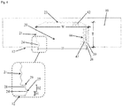
- Figs. 1A and 1B show a schematic view of two different a tuft picking devices 50 for brush making machines which preferably use an anchor-free process for mounting filament tufts into a brush, in particular into a toothbrush.
- the tuft picking devices 50 comprise at least a tuft picker 10 and a filament container 40. Further components which might belong to the tuft picking device 50 are not shown in order to facilitate Figs. 1A and 1B .
- the filament container 40 is suitable for holding a plurality of loose filaments 42 in a mutually parallel condition. That means the filaments 42 are located with parallel length axes in the filament container 40, wherein the length axes of the filaments 42 are parallel to the side walls of the filament container 40.
- the filaments 42 maybe for example monofilaments made from plastic material such as polyamide (PA), in particular PA 6.10 or PA 6.12.
- the diameter of the filament may be in the range from about 0.1 mm to about 0.5 mm or and the filaments may be cut into pieces of a length in the range of about 7mm to about 13 mm.
- the filament container 40 may be of any geometrical shape as long as the filaments 42 can be stored therein.
- the filament container 40 comprises two side walls which are immovable, one movable side wall and one open side.
- the movable side wall is located opposite to the open side and is moved into the direction of the open side, thereby moving the plurality of filaments 42 stored in the filament container 40 in the same direction.
- the filaments 42 are in contact with one of the different tuft pickers 10.
- the tuft picker 10 shown in Fig. 1A comprises four tuft picking notches 20 which are each suitable to take up filaments 42 from the filament container 40.
- the surface contour of the tuft picker 10 is straight or linear.
- Said kind of tuft picker 10 might also be named a picker bar.
- the tuft picker 10 is attached to the tuft picking device 50 in such that the tuft picker 10 can be moved linearly.
- the movement is a bidirectional linear movement along the open side of the filament container 40.
- a working stroke -meaning the movement of the tuft picker 10 that brings at least one tuft picking notch 20 into contact with the filaments 42 located in the filament container 40- is a linear movement in one direction.
- the tuft picker 10 is moved along the open side of the filament container 40 until all tuft picking notches 20 are filled with filaments 42. Then, in the position outside the filament container 40 the filaments 42 can be removed from the tuft picking notches 20 in order to be mounted to a brush. Then the tuft picker 10 can be moved in the reverse direction for a further working stroke in order to fill the tuft picking notches again.
- the tuft picker 10 shown in Fig. 1B comprises ten tuft picking notches 20 which are each suitable to take up filaments 42 from the filament container 40.
- the surface contour of said tuft picker 10 is a circle.
- Five tuft picking notches 20 are arranged at opposite halves of the circular tuft picker 10.
- the tuft picker 10 is attached to the tuft picking device 50 in such that the tuft picker 10 can be moved circularly.
- the movement is an unidirectional circular movement along the open side of the filament container 40.
- a working stroke, -meaning the movement of the tuft picker 10 that brings at least one tuft picking notch 20 into contact with the filaments 42 located in the filament container 40- is a circular movement in one direction.
- FIG. 1B comprises ten tuft picking notches 20 which are each suitable to take up filaments 42 from the filament container 40.
- the surface contour of said tuft picker 10 is a circle.
- Five tuft picking notches 20 are arranged at opposite halves of the circular tuft pick
- a working stroke of the tuft picker 10 corresponds to the movement along the open side of the filament container 40 until five tuft picking notches 20 at one side of the tuft picker 10 are filled with filaments 42.
- the other five tuft picking notches 20 are located outside the area of the filament container 40 so that the filaments 42 can be removed from said tuft picking notches 20 easily. That means charging and discharging of five and five tuft picking notches 20 takes place respectively.
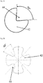
- Fig. 2A shows a schematic sketch of a filament 42 comprising one recess 44 in its circumference.
- the recess 44 might be until the middle of the filament 42 as shown or might be less deep.
- the included angle of the recess 44 is about 90°.
- the diameter of the filament 42 may be in the range of from about 0.18mm to about 0.35mm.
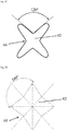
- Figs. 2B , 2C and 2D show a filament 42 comprising four recesses 44 in their circumference, respectively.
- the four recesses 44 are arranged regularly around the circumference of the filament 42, thereby forming an X-shaped filament. Different forms and sizes of recesses are shown in Fig. 2B , 2C and 2D .
- the maximal dimension of an X-shaped filament 42 may be in the range of from about 0.18mm to about 0.35mm.
- the included angle of each of the recesses 44 of the X-shaped filament 42 may be in the range of from about 40° to about 160°. Different included angles are shown, namely 40° ( Fig. 2B ), 120° ( Fig. 2C ) and 160° ( Fig. 2D ).
- the depth of the recesses 44 is less than until the middle of the filament in order to have a robust bulk in the middle of the filament 42.
- the four recesses 44 may be equal to each other in form, shape, size and opening angle as shown or may be different to each other.
- At least the two opposite recesses 44 are preferably equally formed compared to each other.
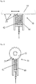
- Figs. 3A and B shows schematically two embodiments of a tuft picking notch 20 which might be located in a tuft picker 10 as shown in Figs. 1 .
- the tuft picking notch 20 comprises a first protrusion 24 comprising a top 25 which is located in the layer of the working surface 12 of the tuft picking notch 20. That means a top 25 of the first projection 24 limits an opening 22 of the tuft picking notch 20.
- the tuft picking notch 20 comprises a second protrusion 26 which top 27 is located off-site the working surface 12 of the notch 20.
- Located off-site means herein that the second protrusion 26 is located inside of the notch 20, in particular the top 27 of the second protrusion 26 is located inside the tuft picking notch 20. That means the opening 22 is not limited by the top 27 of the second protrusion 26.
- a distance D1 from the top 27 of the second protrusion 26 to the working surface 12 and the projection of the top 27 into the notch 20 are in the range of about 0.08mm to about 0.3mm.
- the second projection 26 is formed symmetrically, thus comprising a line of reflection symmetry S crossing the top 27 of the projection 26.
- the angle ⁇ between the working surface 12 of the tuft picker 10 and the line of reflection symmetry S crossing the top 27 of the second projection 26 is in the range of about 30°. If the contour of the tuft picker 10 is linear the angle ⁇ is measured between the line of reflection symmetry S of the second projection 26 and the working surface 12. If the contour of the tuft picker 10 is circular the angle ⁇ is measured between the line of reflection symmetry S of the second projection 26 and the tangent tangenting the working surface 12 of the tuft picker 10 at the middle of the opening 22 of the tuft picking notch 20. If the tuft picker 10 is a circular arc the circular arc comprises preferably a curvature/diameter in the range from 80mm to 300mm, more preferred with a curvature/diameter in the range from 100mm to 200mm.
- Fig. 3B shows an alternative embodiment of the tuft picking notch 20 shown in Fig. 3A .
- the tuft picking notch 20 shown in Fig. 3B is a symmetrical notch 20. That means the first projection 24 and the second projection 26 are formed equally and located equally on both sides of the opening 22 so that the tuft picking notch 20 comprises a line of reflection from the middle of the opening 22 to the middle of the bottom 23 of the notch 20.
- the top 25 of the first projection 24 and the top 27 of the second projection 26 are located off-site the working surface 12 of the notch 20.
- An angle ⁇ is measured between the line of reflection symmetry S of the first and second projections 24, 26 and the working surface 12.
- the angle ⁇ and the distance D1 for the first and second projection 24, 26 are identical.
- the angle ⁇ might be about 30°
- the distance D1 and the projection of the tops 25, 27 into the notch 20 might be in the range of about 0.08mm to about 0.3mm.
- the tuft picking notch 20 shown in Figs. 3A and 3B is a circular notch 20.
- the width W is identical to the diameter of the circular notch 20.
- a suitable width W is in the range of from about 0.5mm to about 5 mm.
- the depth T of the tuft picking notch 20 ranges from a bottom 23 of the notch 20 to the opening 22 of the notch 20.
- the depth T is smaller than the width W due to the flat opening 22.
- a suitable depth T is in the range of from about 0.5mm to about 4 mm.
- Fig. 4 shows another embodiment of a tuft picking notch 20.
- the tuft picking notch 20 shown in Fig. 4 has four protrusions 24, 26, 28, 30.
- the first protrusion 24 and the second protrusion 26 are located off-site the working surface 12 at opposite sides of the opening 22.
- the third protrusion 28 is located adjacent to the first protrusion 24 inside of the tuft picking notch 20 and the fourth protrusion 30 is located adjacent to the second protrusion 26 inside of the tuft picking notch 20.
- a distance D1 from the top 25 of the first protrusion 24 to the working surface 12 is in the range of about 0.08mm to about 0.3mm a distance D1 from the top of the second protrusion 26 to the working surface 12 is in the same range.
- a distance D2 from the top 29 of the third protrusion 28 to the top 25 of the first protrusion 24 is smaller than the distance D1, in particular about 10% smaller than the distance D1.
- a distance D2 from the top of the fourth protrusion 30 to the top of the second protrusion 26 is the same than between the first and third protrusion.
- the tuft picking notch 20 is symmetrically formed. That means the four projection 24, 26, 28, 30 are also symmetrically formed.
- the angle ⁇ between the working surface 12 of the tuft picker 10 and the line of reflection symmetry S crossing the tops of the first and second projections 24, 26 is in the range of about 30°.
- the angle ⁇ between the working surface 12 of the tuft picker 10 and the line of reflection symmetry S crossing the tops of the third and fourth projections 28, 30 is in the range of about 30-60°.
- the third and fourth projections 28, 30 project about 10% less into the notch 20, i.e. the tops of the third and fourth projections 28, 30 project less into the notch 20 than the tops of the first and second projections 24, 26 and the opening 22 is smaller than the width W of the notch 20.
- the tuft picking notch 20 shown in Fig. 4 is a rectangle, wherein the side walls 21 and the bottom 23 of the notch 20 are irregularly shaped, e.g. wherein the side walls 21 and the bottom 23 of the notch 20 are undulated comprising alternating depressions and elevations. In addition the edges of the rectangle are flattened.
- the depth T of the tuft picking notch 20 ranging from the base of the bottom 23 to the opening 22 of the notch 20 is in the range of from 0.5mm to 3mm, wherein the elevations at the bottom are about 0.05mm.
- the width W of the notch 20 measured at the base of the side walls 21 is in the range of from 1.5mm to 6mm, wherein the elevations at the bottom are about 0.05mm.
Landscapes
- Engineering & Computer Science (AREA)
- Manufacturing & Machinery (AREA)
- Brushes (AREA)
Claims (15)
- Büschelaufnehmer (10) für eine Büschelaufnahmevorrichtung (50), wobei eine Arbeitsoberfläche (12) des Büschelaufnehmers (10) wenigstens eine Büschelaufnahmekerbe (20) mit einer Tiefe (T), einer Breite (W) und einer Öffnung (22) umfasst, wobei ein erster Vorsprung (24) und ein zweiter Vorsprung (26) die Öffnung (22) der Büschelaufnahmekerbe (20) verglichen mit einer inneren Breite (W) verringern,
dadurch gekennzeichnet, dass
wenigstens ein oberes Ende (25, 27) des ersten und/oder zweiten Vorsprungs (24, 26) außerhalb der Arbeitsoberfläche (12) des Büschelaufnehmers (10) und in der Kerbe (20) liegt, wobei ein Abstand (D1) von dem wenigstens einen oberen Ende (25, 27) zur Arbeitsoberfläche (12) des Büschelaufnehmers (10) im Bereich von 0,05 mm bis 0,5 mm liegt, und wobei ein Winkel (α) zwischen der Arbeitsoberfläche (12) des Büschelaufnehmers (10) und einer Spiegelsymmetrielinie (S1, S2), die das wenigstens eine obere Ende (25, 27) durchläuft, im Bereich von 1° bis 45° liegt. - Büschelaufnehmer (10) nach Anspruch 1, wobei der Winkel (α) im Bereich von 3° bis 40°, vorzugsweise im Bereich von 3° bis 35°, mehr bevorzugt im Bereich von 5° bis 30°, mehr bevorzugt im Bereich von 5° bis 20°, mehr bevorzugt im Bereich von 8° bis 15° liegt.
- Büschelaufnehmer (10) nach Anspruch 1 oder 2, wobei die Arbeitsoberfläche (12) des Büschelaufnehmers (10) eine lineare Oberfläche oder ein Kreisbogen ist, umfassend eine Krümmung/einen Durchmesser im Bereich von 80 mm bis 300 mm, vorzugsweise im Bereich von 100 mm bis 200 mm.
- Büschelaufnehmer (10) nach einem der Ansprüche 1 bis 3, wobei der Abstand (D1) von dem wenigstens einen oberen Ende (25, 27) des ersten und/oder des zweiten Vorsprungs (24, 26) zur Arbeitsoberfläche (12) im Bereich von 0,05 mm bis 0,4 mm, vorzugsweise im Bereich von 0,05 mm bis 0,35 mm, mehr bevorzugt im Bereich von 0,08 mm bis 0,3 mm liegt.
- Büschelaufnehmer (10) nach einem der Ansprüche 1 bis 4, wobei das obere Ende (25, 27) des ersten und/oder des zweiten Vorsprungs (24, 26) im Bereich von 0,025 mm bis 0,25 mm, vorzugsweise im Bereich von 0,025 mm bis 0,2 mm, mehr bevorzugt von 0,04 mm bis 0,15 mm in die Kerbe (20) hineinragt.
- Büschelaufnehmer (10) nach einem der Ansprüche 1 bis 5, wobei die oberen Enden (25, 27) des ersten und des zweiten Vorsprungs (24, 26) außerhalb der Arbeitsoberfläche (12) des Büschelaufnehmers (10) und in der Kerbe (20) liegen.
- Büschelaufnehmer (10) nach Anspruch 6, wobei der Winkel (α) zwischen der Arbeitsoberfläche (12) des Büschelaufnehmers (10) und der Spiegelsymmetrielinie (S1), die das obere Ende (25) des ersten Vorsprungs (24) durchläuft, gleich dem Winkel (α) zwischen der Arbeitsoberfläche (12) des Büschelaufnehmers (10) und der Spiegelsymmetrielinie (S2), die das obere Ende (27) des zweiten Vorsprungs (26) durchläuft, ist.
- Büschelaufnehmer (10) nach einem der Ansprüche 1 bis 7, wobei die Büschelaufnahmekerbe (20) einen dritten und/oder einen vierten Vorsprung (28, 30) umfasst, die in der Kerbe (20) benachbart zu dem ersten und/oder dem zweiten Vorsprung (24, 26) liegen.
- Büschelaufnehmer (10) nach Anspruch 8, wobei das obere Ende (29) des dritten Vorsprungs (28) und/oder das obere Ende (31) des vierten Vorsprungs (30) weniger in die Kerbe (20) hineinragen als die oberen Enden (25, 27) des ersten und/oder des zweiten Vorsprungs (24, 26), vorzugsweise 5 % weniger, mehr bevorzugt 10 % weniger, mehr bevorzugt 15 % weniger.
- Büschelaufnehmer (10) nach einem der Ansprüche 1 bis 9, wobei die Breite (W) der Kerbe (20) entlang der Tiefe (T) der Kerbe (20) variiert, vorzugsweise wobei die Breite (W) am Boden (23) der Kerbe (20) größer ist als jenseits des ersten und/oder des zweiten Vorsprungs (24, 26) und/oder jenseits des dritten und/oder des vierten Vorsprungs (28, 30).
- Büschelaufnehmer (10) nach einem der Ansprüche 1 bis 10, wobei die Breite (W) der Büschelaufnahmekerbe (20) größer ist als die Tiefe (T) der Büschelaufnahmekerbe (20), vorzugsweise wobei die Breite (W) im Bereich von 0,5 mm bis 10 mm liegt, und/oder wobei die Tiefe (T) im Bereich von 0,5 mm bis 5 mm liegt.
- Büschelaufnehmer (10) nach einem der Ansprüche 1 bis 11, wobei die Büschelaufnahmekerbe (20) in der Form eines Kreises, eines Ovals, eines Polygons, vorzugsweise eines konvexen Polygons, eines zyklischen Polygons, eines regelmäßigen Vierecks, eines unregelmäßigen Vierecks, eines Polygons mit abgerundeten Winkeln oder einer Kombination davon vorliegt.
- Büschelaufnehmer (10) nach einem der Ansprüche 6 bis 12, wobei die Kerbe (20) eine Spiegelsymmetrielinie (S), vorzugsweise von der Mitte der Öffnung (22) zur Mitte des Bodens (23) umfasst.
- Büschelaufnehmer (10) nach einem der Ansprüche 1 bis 13, wobei der Boden (23) und/oder die Seitenwände (21) der Kerbe (20) eine Vielzahl von Vertiefungen und Erhebungen umfasst, vorzugsweise wobei der Boden (23) und/oder die Seitenwände (21) der Kerbe (20) gewellt sind.
- Büschelaufnehmer (10) nach Anspruch 14, wobei eine Vertiefung in den Seitenwänden (21) benachbart zu dem ersten und/oder dem zweiten Vorsprung (24, 26) oder benachbart zu dem dritten und/oder dem vierten Vorsprung (28, 30) angeordnet ist.
Priority Applications (4)
| Application Number | Priority Date | Filing Date | Title |
|---|---|---|---|
| US15/246,480 US10492597B2 (en) | 2015-09-03 | 2016-08-24 | Tuft picker for a tuft-picking device of a brush-making machine |
| PCT/US2016/048304 WO2017040132A1 (en) | 2015-09-03 | 2016-08-24 | Tuft picker for a tuft picking device of a brush making machine |
| BR112018003946-2A BR112018003946B1 (pt) | 2015-09-03 | 2016-08-24 | Seletor de tufo para um dispositivo de seleção de tufo de uma máquina de fabricação de escova |
| CN201680050293.1A CN107920656B (zh) | 2015-09-03 | 2016-08-24 | 用于制刷机的簇绒拣选装置的簇绒拣选器 |
Applications Claiming Priority (1)
| Application Number | Priority Date | Filing Date | Title |
|---|---|---|---|
| EP15183598 | 2015-09-03 |
Publications (2)
| Publication Number | Publication Date |
|---|---|
| EP3138438A1 EP3138438A1 (de) | 2017-03-08 |
| EP3138438B1 true EP3138438B1 (de) | 2018-09-05 |
Family
ID=54064163
Family Applications (1)
| Application Number | Title | Priority Date | Filing Date |
|---|---|---|---|
| EP16177575.4A Active EP3138438B1 (de) | 2015-09-03 | 2016-07-01 | Büschelaufnehmer für eine büschelaufnahmevorrichtung einer bürstenherstellungsmaschine |
Country Status (5)
| Country | Link |
|---|---|
| US (1) | US10492597B2 (de) |
| EP (1) | EP3138438B1 (de) |
| CN (1) | CN107920656B (de) |
| BR (1) | BR112018003946B1 (de) |
| WO (1) | WO2017040132A1 (de) |
Families Citing this family (3)
| Publication number | Priority date | Publication date | Assignee | Title |
|---|---|---|---|---|
| DE102016011337A1 (de) * | 2016-09-21 | 2018-03-22 | Zahoransky Ag | Bündelabnahmevorrichtung, Bürstenherstellungsmaschine, Verfahren zur Herstellung eines Bündelabnehmers sowie Verfahren zur Herstellung eines Gegenstücks einer Bündelabnahmevorrichtung |
| EP3351142B1 (de) | 2017-01-24 | 2019-10-16 | The Procter and Gamble Company | Büschelaufnehmer für eine bürstenherstellungsmaschine |
| EP3351143B1 (de) | 2017-01-24 | 2019-11-06 | The Procter and Gamble Company | Büschelaufnehmer für eine bürstenherstellungsmaschine |
Family Cites Families (55)
| Publication number | Priority date | Publication date | Assignee | Title |
|---|---|---|---|---|
| US1664424A (en) | 1924-04-01 | 1928-04-03 | Toledo Automatic Brush Machine | Tuft-separating mechanism for brush machines |
| GB418967A (en) | 1933-07-08 | 1934-11-02 | Arthur Zahoransky | Improvements in and relating to the fixing of bristles in brush and broom stocks |
| US2349532A (en) | 1942-11-13 | 1944-05-23 | Fisher Brush Machinery Corp | Tuft-making device for automatic brushmaking machines |
| US3167355A (en) | 1963-01-07 | 1965-01-26 | David F Demarest | Broom bristle segregating machine |
| GB1146518A (en) | 1965-11-16 | 1969-03-26 | Spojene Kartacovny | Improved device for separating bundles of predetermined size from a stack of fine hair, bristles or the like fibres |
| US3606472A (en) | 1970-01-27 | 1971-09-20 | Poloron Products Inc | Apparatus for manufacturing articles such as brushes and simulated tree branches |
| BE765338A (nl) | 1971-04-06 | 1971-08-30 | Boucherie Nv G B | Inrichting voor het voeden van het vulwerktuig van een borstelvervaardigingsmachine met minstens twee soorten vezels. |
| DE2128774A1 (de) | 1971-04-06 | 1972-10-26 | G B Boucherie, N V , Izegem (Bei gien) | Vorrichtung zum Speisen des Fullge rates einer Burstenherstellungsmaschine mit wenigstens zwei Faserarten |
| DE2911668A1 (de) | 1979-03-24 | 1980-09-25 | Boucherie Nv G B | Doppelfasermagazin fuer buerstenherstellungsmaschinen |
| DE3016790A1 (de) | 1980-05-02 | 1981-11-05 | Fa. Anton Zahoransky, 7868 Todtnau | Buerstenherstellungsmaschine und verfahren zum herstellen von buersten |
| BE902770A (nl) | 1985-06-28 | 1985-12-30 | Boucherie Nv G B | Inrichting voor de vezeltoevoer aan een vulwerktuig van een borstelvervaardigingsmachine. |
| US4693519A (en) | 1986-02-04 | 1987-09-15 | Tucel Industries Inc. | Filament stock box |
| JPH01254112A (ja) | 1988-04-01 | 1989-10-11 | Kao Corp | 植毛機のピッカー |
| BE1002082A6 (nl) | 1988-06-17 | 1990-06-19 | Boucherie Nv G B | Verbeterde inrichting voor de vezeltoevoer aan een vulwerktuig van een borstelvervaardigingsmachine. |
| EP0405204B1 (de) | 1989-06-24 | 1994-09-07 | Frisetta GmbH | Verfahren und Vorrichtung zum Herstellen von Borstenfeldern oder Borstenbündeln |
| US5165759A (en) | 1989-12-13 | 1992-11-24 | Tucel Industries, Inc. | Fusing machine |
| DE69014084T2 (de) | 1989-12-13 | 1995-03-23 | Tucel Industries | Verfahren und Vorrichtung zur Herstellung von Borstenbüscheln. |
| DE4027288C2 (de) | 1990-08-29 | 2001-08-09 | Coronet Werke Gmbh | Vorrichtung zur Erzeugung von Borstenbündeln und Verfahren zur Herstellung von Borstenwaren mittels der Vorrichtung |
| DE4040297C2 (de) | 1990-12-17 | 2003-08-21 | Zahoransky Anton Gmbh & Co | Bürstenherstellungsmaschine |
| JP2506000B2 (ja) | 1991-07-10 | 1996-06-12 | 花王株式会社 | 植毛機のピッカ― |
| JP2922339B2 (ja) | 1991-07-10 | 1999-07-19 | ミノルタ株式会社 | 画像形成装置用ブラシの製法 |
| GB2287901B (en) * | 1994-03-29 | 1998-05-06 | Boucherie Nv G B | A brush making machine |
| DE4411652C2 (de) | 1994-04-02 | 2003-10-09 | Zahoransky Anton Gmbh & Co | Bürstenherstellungsmaschine |
| BE1008378A3 (nl) | 1994-05-09 | 1996-04-02 | Boucherie Nv G B | Werkwijze en inrichting voor het toevoeren van vezels aan een vulwerktuig bij een borstelvervaardigingsmachine. |
| DE69725887T2 (de) | 1996-07-25 | 2004-09-09 | Whitehill Oral Technologies Inc. | Zahnbürste mit verbesserter reinigungs- und abtrieb- wirksamkeit |
| DE19728442A1 (de) | 1997-07-03 | 1999-01-07 | Zahoransky Anton Gmbh & Co | Bürstenherstellungsmaschine |
| DE29715117U1 (de) | 1997-08-22 | 1998-12-24 | G.B. Boucherie N.V., Izegem | Vorrichtung zur Entnahme von einzelnen Faserbündeln aus Faserkästen einer Bürstenherstellungsmaschine |
| DE19745024A1 (de) | 1997-10-11 | 1999-04-15 | Zahoransky Anton Gmbh & Co | Bürstenherstellungsmaschine |
| BE1011547A3 (nl) | 1997-11-14 | 1999-10-05 | Boucherie Nv G B | Inrichting voor het toevoeren van vezels aan een vulwerktuig bij een borstelvervaardigingsmachine. |
| US6290302B1 (en) | 1998-07-14 | 2001-09-18 | Firma G.B. Boucherie, Naamloze Vennootschap | Method for manufacturing brushes and brush manufacturing machine applying this method |
| WO2000010814A1 (de) | 1998-08-17 | 2000-03-02 | M + C Schiffer Gmbh | Verfahren und vorrichtung zur herstellung von borstenbündeln |
| DE19939333A1 (de) | 1999-08-19 | 2001-02-22 | Zahoransky Anton Gmbh & Co | Bürstenherstellungsmaschine |
| BE1013374A3 (nl) | 2000-04-04 | 2001-12-04 | Boucherie Nv G B | Werkwijze en inrichting voor het vervaardigen van borstels. |
| US20030135547A1 (en) * | 2001-07-23 | 2003-07-17 | Kent J. Thomas | Extensible modular communication executive with active message queue and intelligent message pre-validation |
| JP3916939B2 (ja) | 2001-12-07 | 2007-05-23 | ライオン株式会社 | ブラシ用植毛装置 |
| DE10346867A1 (de) * | 2003-10-09 | 2005-05-04 | Schiffer Fa M & C | Verfahren zur Herstellung von Bürsten, insbesondere Zahnbürsten |
| BE1015733A3 (nl) | 2003-11-28 | 2005-07-05 | Boucherie Nv G B | Inrichting voor het vervaardigen van borstels en werkwijze daarbij toegepast. |
| DE20319767U1 (de) | 2003-12-19 | 2005-05-04 | M + C Schiffer Gmbh | Vorrichtung zum Herstellen von Bürsten |
| US8172336B2 (en) * | 2004-10-22 | 2012-05-08 | Firma G. B. Boucherie N.V. | Tuft picking device for a brush making machine |
| DE202004016409U1 (de) * | 2004-10-22 | 2005-02-24 | Firma G.B. Boucherie N.V. | Bündelabnahmevorrichtung für eine Bürstenherstellungsmaschine |
| DE102005045827B4 (de) | 2005-09-24 | 2019-10-24 | Zahoransky Ag | Verfahren und Maschine zum Herstellen von Rundbürsten |
| DE102005056968B4 (de) | 2005-11-30 | 2019-05-29 | Zahoransky Ag | Stopfeinrichtung |
| DE202005020231U1 (de) * | 2005-12-27 | 2006-03-30 | Firma G.B. Boucherie N.V. | Bürsten-Stopfmaschine |
| DE102007047066B4 (de) | 2007-10-01 | 2016-08-11 | Zahoransky Ag | Bürstenherstellungsmaschine |
| DE202007014431U1 (de) | 2007-10-15 | 2008-01-10 | Firma G.B. Boucherie N.V. | Stopfmaschine für Besen oder Bürsten |
| DE102008059121B4 (de) | 2008-11-26 | 2020-07-02 | Zahoransky Ag | Bürstenherstellungsmaschine |
| DE102009013723A1 (de) | 2009-03-20 | 2010-09-23 | Zahoransky Ag | Verfahren und Vorrichtung zum Herstellen und Bereitstellen von Filamentbündel und Borstenfelder |
| CN201468419U (zh) | 2009-05-07 | 2010-05-19 | 陈崧 | 冷光光波美白牙刷 |
| CN201468428U (zh) * | 2009-08-04 | 2010-05-19 | 桐乡市永鑫制刷机械厂 | 适用于圆盘式输送装置的条刷机的贮毛器 |
| CN201468429U (zh) * | 2009-08-04 | 2010-05-19 | 桐乡市永鑫制刷机械厂 | 条刷机的给毛盘 |
| CN201468430U (zh) * | 2009-08-04 | 2010-05-19 | 桐乡市永鑫制刷机械厂 | 条刷机的给毛装置 |
| JP5469968B2 (ja) * | 2009-09-14 | 2014-04-16 | ライオン株式会社 | 植毛装置 |
| DE102010015118A1 (de) * | 2010-04-16 | 2011-10-20 | Zahoransky Ag | Vorrichtung zum Herstellen von Borstenfeldern für Bürsten |
| DE102010055702A1 (de) | 2010-12-22 | 2012-06-28 | Gb Boucherie Nv | Verfahren zum Betreiben einer Borstenbündelvereinzelungsvorrichtung sowie Borstenbündelvereinzelungsvorrichtung |
| EP3138436A1 (de) | 2015-09-03 | 2017-03-08 | The Procter and Gamble Company | Büschelaufnahmevorrichtung für eine bürstenherstellungsmaschine |
-
2016
- 2016-07-01 EP EP16177575.4A patent/EP3138438B1/de active Active
- 2016-08-24 CN CN201680050293.1A patent/CN107920656B/zh active Active
- 2016-08-24 BR BR112018003946-2A patent/BR112018003946B1/pt active IP Right Grant
- 2016-08-24 WO PCT/US2016/048304 patent/WO2017040132A1/en not_active Ceased
- 2016-08-24 US US15/246,480 patent/US10492597B2/en active Active
Also Published As
| Publication number | Publication date |
|---|---|
| CN107920656B (zh) | 2020-07-28 |
| EP3138438A1 (de) | 2017-03-08 |
| BR112018003946A2 (pt) | 2018-09-25 |
| CN107920656A (zh) | 2018-04-17 |
| US10492597B2 (en) | 2019-12-03 |
| WO2017040132A1 (en) | 2017-03-09 |
| BR112018003946B1 (pt) | 2022-02-08 |
| US20170065073A1 (en) | 2017-03-09 |
Similar Documents
| Publication | Publication Date | Title |
|---|---|---|
| US8608251B2 (en) | Brush head manufacturing method | |
| EP2385772B1 (de) | Zahnbürste | |
| US10398220B2 (en) | Tuft-picking device for a brush-making machine | |
| EP3138438B1 (de) | Büschelaufnehmer für eine büschelaufnahmevorrichtung einer bürstenherstellungsmaschine | |
| US10517389B2 (en) | Process and apparatus for creating tufts for tufted article | |
| US11089863B2 (en) | Tuft picker for a brush making machine | |
| US6361120B1 (en) | Brush tufting | |
| US11058214B2 (en) | Tuft picker for a brush making machine | |
| US20160353874A1 (en) | Device for filament end-rounding and a method for end-rounding (tooth)brush filaments | |
| US6354911B1 (en) | Method and apparatus for end-rounding bristles | |
| KR102120282B1 (ko) | 칫솔 |
Legal Events
| Date | Code | Title | Description |
|---|---|---|---|
| PUAI | Public reference made under article 153(3) epc to a published international application that has entered the european phase |
Free format text: ORIGINAL CODE: 0009012 |
|
| STAA | Information on the status of an ep patent application or granted ep patent |
Free format text: STATUS: THE APPLICATION HAS BEEN PUBLISHED |
|
| AK | Designated contracting states |
Kind code of ref document: A1 Designated state(s): AL AT BE BG CH CY CZ DE DK EE ES FI FR GB GR HR HU IE IS IT LI LT LU LV MC MK MT NL NO PL PT RO RS SE SI SK SM TR |
|
| AX | Request for extension of the european patent |
Extension state: BA ME |
|
| STAA | Information on the status of an ep patent application or granted ep patent |
Free format text: STATUS: REQUEST FOR EXAMINATION WAS MADE |
|
| 17P | Request for examination filed |
Effective date: 20170803 |
|
| RBV | Designated contracting states (corrected) |
Designated state(s): AL AT BE BG CH CY CZ DE DK EE ES FI FR GB GR HR HU IE IS IT LI LT LU LV MC MK MT NL NO PL PT RO RS SE SI SK SM TR |
|
| GRAP | Despatch of communication of intention to grant a patent |
Free format text: ORIGINAL CODE: EPIDOSNIGR1 |
|
| STAA | Information on the status of an ep patent application or granted ep patent |
Free format text: STATUS: GRANT OF PATENT IS INTENDED |
|
| RIC1 | Information provided on ipc code assigned before grant |
Ipc: A46D 3/08 20060101AFI20171204BHEP Ipc: A46D 3/04 20060101ALI20171204BHEP Ipc: A46D 1/08 20060101ALI20171204BHEP Ipc: A46D 7/00 20060101ALI20171204BHEP |
|
| INTG | Intention to grant announced |
Effective date: 20180110 |
|
| GRAJ | Information related to disapproval of communication of intention to grant by the applicant or resumption of examination proceedings by the epo deleted |
Free format text: ORIGINAL CODE: EPIDOSDIGR1 |
|
| STAA | Information on the status of an ep patent application or granted ep patent |
Free format text: STATUS: REQUEST FOR EXAMINATION WAS MADE |
|
| INTC | Intention to grant announced (deleted) | ||
| GRAP | Despatch of communication of intention to grant a patent |
Free format text: ORIGINAL CODE: EPIDOSNIGR1 |
|
| STAA | Information on the status of an ep patent application or granted ep patent |
Free format text: STATUS: GRANT OF PATENT IS INTENDED |
|
| INTG | Intention to grant announced |
Effective date: 20180410 |
|
| GRAS | Grant fee paid |
Free format text: ORIGINAL CODE: EPIDOSNIGR3 |
|
| GRAA | (expected) grant |
Free format text: ORIGINAL CODE: 0009210 |
|
| STAA | Information on the status of an ep patent application or granted ep patent |
Free format text: STATUS: THE PATENT HAS BEEN GRANTED |
|
| AK | Designated contracting states |
Kind code of ref document: B1 Designated state(s): AL AT BE BG CH CY CZ DE DK EE ES FI FR GB GR HR HU IE IS IT LI LT LU LV MC MK MT NL NO PL PT RO RS SE SI SK SM TR |
|
| REG | Reference to a national code |
Ref country code: GB Ref legal event code: FG4D |
|
| REG | Reference to a national code |
Ref country code: CH Ref legal event code: EP |
|
| REG | Reference to a national code |
Ref country code: AT Ref legal event code: REF Ref document number: 1036826 Country of ref document: AT Kind code of ref document: T Effective date: 20180915 |
|
| REG | Reference to a national code |
Ref country code: IE Ref legal event code: FG4D |
|
| REG | Reference to a national code |
Ref country code: DE Ref legal event code: R096 Ref document number: 602016005299 Country of ref document: DE |
|
| REG | Reference to a national code |
Ref country code: NL Ref legal event code: MP Effective date: 20180905 |
|
| REG | Reference to a national code |
Ref country code: LT Ref legal event code: MG4D |
|
| PG25 | Lapsed in a contracting state [announced via postgrant information from national office to epo] |
Ref country code: NO Free format text: LAPSE BECAUSE OF FAILURE TO SUBMIT A TRANSLATION OF THE DESCRIPTION OR TO PAY THE FEE WITHIN THE PRESCRIBED TIME-LIMIT Effective date: 20181205 Ref country code: BG Free format text: LAPSE BECAUSE OF FAILURE TO SUBMIT A TRANSLATION OF THE DESCRIPTION OR TO PAY THE FEE WITHIN THE PRESCRIBED TIME-LIMIT Effective date: 20181205 Ref country code: GR Free format text: LAPSE BECAUSE OF FAILURE TO SUBMIT A TRANSLATION OF THE DESCRIPTION OR TO PAY THE FEE WITHIN THE PRESCRIBED TIME-LIMIT Effective date: 20181206 Ref country code: RS Free format text: LAPSE BECAUSE OF FAILURE TO SUBMIT A TRANSLATION OF THE DESCRIPTION OR TO PAY THE FEE WITHIN THE PRESCRIBED TIME-LIMIT Effective date: 20180905 Ref country code: FI Free format text: LAPSE BECAUSE OF FAILURE TO SUBMIT A TRANSLATION OF THE DESCRIPTION OR TO PAY THE FEE WITHIN THE PRESCRIBED TIME-LIMIT Effective date: 20180905 Ref country code: LT Free format text: LAPSE BECAUSE OF FAILURE TO SUBMIT A TRANSLATION OF THE DESCRIPTION OR TO PAY THE FEE WITHIN THE PRESCRIBED TIME-LIMIT Effective date: 20180905 Ref country code: SE Free format text: LAPSE BECAUSE OF FAILURE TO SUBMIT A TRANSLATION OF THE DESCRIPTION OR TO PAY THE FEE WITHIN THE PRESCRIBED TIME-LIMIT Effective date: 20180905 |
|
| REG | Reference to a national code |
Ref country code: AT Ref legal event code: MK05 Ref document number: 1036826 Country of ref document: AT Kind code of ref document: T Effective date: 20180905 |
|
| PG25 | Lapsed in a contracting state [announced via postgrant information from national office to epo] |
Ref country code: AL Free format text: LAPSE BECAUSE OF FAILURE TO SUBMIT A TRANSLATION OF THE DESCRIPTION OR TO PAY THE FEE WITHIN THE PRESCRIBED TIME-LIMIT Effective date: 20180905 Ref country code: LV Free format text: LAPSE BECAUSE OF FAILURE TO SUBMIT A TRANSLATION OF THE DESCRIPTION OR TO PAY THE FEE WITHIN THE PRESCRIBED TIME-LIMIT Effective date: 20180905 Ref country code: HR Free format text: LAPSE BECAUSE OF FAILURE TO SUBMIT A TRANSLATION OF THE DESCRIPTION OR TO PAY THE FEE WITHIN THE PRESCRIBED TIME-LIMIT Effective date: 20180905 |
|
| PG25 | Lapsed in a contracting state [announced via postgrant information from national office to epo] |
Ref country code: EE Free format text: LAPSE BECAUSE OF FAILURE TO SUBMIT A TRANSLATION OF THE DESCRIPTION OR TO PAY THE FEE WITHIN THE PRESCRIBED TIME-LIMIT Effective date: 20180905 Ref country code: PL Free format text: LAPSE BECAUSE OF FAILURE TO SUBMIT A TRANSLATION OF THE DESCRIPTION OR TO PAY THE FEE WITHIN THE PRESCRIBED TIME-LIMIT Effective date: 20180905 Ref country code: IS Free format text: LAPSE BECAUSE OF FAILURE TO SUBMIT A TRANSLATION OF THE DESCRIPTION OR TO PAY THE FEE WITHIN THE PRESCRIBED TIME-LIMIT Effective date: 20190105 Ref country code: ES Free format text: LAPSE BECAUSE OF FAILURE TO SUBMIT A TRANSLATION OF THE DESCRIPTION OR TO PAY THE FEE WITHIN THE PRESCRIBED TIME-LIMIT Effective date: 20180905 Ref country code: RO Free format text: LAPSE BECAUSE OF FAILURE TO SUBMIT A TRANSLATION OF THE DESCRIPTION OR TO PAY THE FEE WITHIN THE PRESCRIBED TIME-LIMIT Effective date: 20180905 Ref country code: NL Free format text: LAPSE BECAUSE OF FAILURE TO SUBMIT A TRANSLATION OF THE DESCRIPTION OR TO PAY THE FEE WITHIN THE PRESCRIBED TIME-LIMIT Effective date: 20180905 Ref country code: CZ Free format text: LAPSE BECAUSE OF FAILURE TO SUBMIT A TRANSLATION OF THE DESCRIPTION OR TO PAY THE FEE WITHIN THE PRESCRIBED TIME-LIMIT Effective date: 20180905 Ref country code: AT Free format text: LAPSE BECAUSE OF FAILURE TO SUBMIT A TRANSLATION OF THE DESCRIPTION OR TO PAY THE FEE WITHIN THE PRESCRIBED TIME-LIMIT Effective date: 20180905 |
|
| PG25 | Lapsed in a contracting state [announced via postgrant information from national office to epo] |
Ref country code: SM Free format text: LAPSE BECAUSE OF FAILURE TO SUBMIT A TRANSLATION OF THE DESCRIPTION OR TO PAY THE FEE WITHIN THE PRESCRIBED TIME-LIMIT Effective date: 20180905 Ref country code: PT Free format text: LAPSE BECAUSE OF FAILURE TO SUBMIT A TRANSLATION OF THE DESCRIPTION OR TO PAY THE FEE WITHIN THE PRESCRIBED TIME-LIMIT Effective date: 20190105 Ref country code: SK Free format text: LAPSE BECAUSE OF FAILURE TO SUBMIT A TRANSLATION OF THE DESCRIPTION OR TO PAY THE FEE WITHIN THE PRESCRIBED TIME-LIMIT Effective date: 20180905 |
|
| REG | Reference to a national code |
Ref country code: DE Ref legal event code: R097 Ref document number: 602016005299 Country of ref document: DE |
|
| PLBE | No opposition filed within time limit |
Free format text: ORIGINAL CODE: 0009261 |
|
| STAA | Information on the status of an ep patent application or granted ep patent |
Free format text: STATUS: NO OPPOSITION FILED WITHIN TIME LIMIT |
|
| PG25 | Lapsed in a contracting state [announced via postgrant information from national office to epo] |
Ref country code: DK Free format text: LAPSE BECAUSE OF FAILURE TO SUBMIT A TRANSLATION OF THE DESCRIPTION OR TO PAY THE FEE WITHIN THE PRESCRIBED TIME-LIMIT Effective date: 20180905 |
|
| 26N | No opposition filed |
Effective date: 20190606 |
|
| PG25 | Lapsed in a contracting state [announced via postgrant information from national office to epo] |
Ref country code: SI Free format text: LAPSE BECAUSE OF FAILURE TO SUBMIT A TRANSLATION OF THE DESCRIPTION OR TO PAY THE FEE WITHIN THE PRESCRIBED TIME-LIMIT Effective date: 20180905 |
|
| PG25 | Lapsed in a contracting state [announced via postgrant information from national office to epo] |
Ref country code: MC Free format text: LAPSE BECAUSE OF FAILURE TO SUBMIT A TRANSLATION OF THE DESCRIPTION OR TO PAY THE FEE WITHIN THE PRESCRIBED TIME-LIMIT Effective date: 20180905 |
|
| PG25 | Lapsed in a contracting state [announced via postgrant information from national office to epo] |
Ref country code: TR Free format text: LAPSE BECAUSE OF FAILURE TO SUBMIT A TRANSLATION OF THE DESCRIPTION OR TO PAY THE FEE WITHIN THE PRESCRIBED TIME-LIMIT Effective date: 20180905 |
|
| PG25 | Lapsed in a contracting state [announced via postgrant information from national office to epo] |
Ref country code: LU Free format text: LAPSE BECAUSE OF NON-PAYMENT OF DUE FEES Effective date: 20190701 |
|
| PG25 | Lapsed in a contracting state [announced via postgrant information from national office to epo] |
Ref country code: FR Free format text: LAPSE BECAUSE OF NON-PAYMENT OF DUE FEES Effective date: 20190731 |
|
| PG25 | Lapsed in a contracting state [announced via postgrant information from national office to epo] |
Ref country code: IE Free format text: LAPSE BECAUSE OF NON-PAYMENT OF DUE FEES Effective date: 20190701 |
|
| GBPC | Gb: european patent ceased through non-payment of renewal fee |
Effective date: 20200701 |
|
| PG25 | Lapsed in a contracting state [announced via postgrant information from national office to epo] |
Ref country code: GB Free format text: LAPSE BECAUSE OF NON-PAYMENT OF DUE FEES Effective date: 20200701 |
|
| PG25 | Lapsed in a contracting state [announced via postgrant information from national office to epo] |
Ref country code: CY Free format text: LAPSE BECAUSE OF FAILURE TO SUBMIT A TRANSLATION OF THE DESCRIPTION OR TO PAY THE FEE WITHIN THE PRESCRIBED TIME-LIMIT Effective date: 20180905 |
|
| PG25 | Lapsed in a contracting state [announced via postgrant information from national office to epo] |
Ref country code: HU Free format text: LAPSE BECAUSE OF FAILURE TO SUBMIT A TRANSLATION OF THE DESCRIPTION OR TO PAY THE FEE WITHIN THE PRESCRIBED TIME-LIMIT; INVALID AB INITIO Effective date: 20160701 Ref country code: MT Free format text: LAPSE BECAUSE OF FAILURE TO SUBMIT A TRANSLATION OF THE DESCRIPTION OR TO PAY THE FEE WITHIN THE PRESCRIBED TIME-LIMIT Effective date: 20180905 |
|
| PG25 | Lapsed in a contracting state [announced via postgrant information from national office to epo] |
Ref country code: MK Free format text: LAPSE BECAUSE OF FAILURE TO SUBMIT A TRANSLATION OF THE DESCRIPTION OR TO PAY THE FEE WITHIN THE PRESCRIBED TIME-LIMIT Effective date: 20180905 |
|
| P01 | Opt-out of the competence of the unified patent court (upc) registered |
Effective date: 20230429 |
|
| PGFP | Annual fee paid to national office [announced via postgrant information from national office to epo] |
Ref country code: BE Payment date: 20250619 Year of fee payment: 10 |
|
| PGFP | Annual fee paid to national office [announced via postgrant information from national office to epo] |
Ref country code: DE Payment date: 20250604 Year of fee payment: 10 |
|
| PGFP | Annual fee paid to national office [announced via postgrant information from national office to epo] |
Ref country code: IT Payment date: 20250623 Year of fee payment: 10 |
|
| PGFP | Annual fee paid to national office [announced via postgrant information from national office to epo] |
Ref country code: CH Payment date: 20250801 Year of fee payment: 10 |