EP3076851B1 - Endoskopkopf und endoskop - Google Patents
Endoskopkopf und endoskop Download PDFInfo
- Publication number
- EP3076851B1 EP3076851B1 EP14806228.4A EP14806228A EP3076851B1 EP 3076851 B1 EP3076851 B1 EP 3076851B1 EP 14806228 A EP14806228 A EP 14806228A EP 3076851 B1 EP3076851 B1 EP 3076851B1
- Authority
- EP
- European Patent Office
- Prior art keywords
- mid
- endoscope head
- endoscope
- shaped element
- conductor track
- Prior art date
- Legal status (The legal status is an assumption and is not a legal conclusion. Google has not performed a legal analysis and makes no representation as to the accuracy of the status listed.)
- Active
Links
Images


Classifications
-
- A—HUMAN NECESSITIES
- A61—MEDICAL OR VETERINARY SCIENCE; HYGIENE
- A61B—DIAGNOSIS; SURGERY; IDENTIFICATION
- A61B1/00—Instruments for performing medical examinations of the interior of cavities or tubes of the body by visual or photographical inspection, e.g. endoscopes; Illuminating arrangements therefor
- A61B1/00064—Constructional details of the endoscope body
- A61B1/00071—Insertion part of the endoscope body
- A61B1/0008—Insertion part of the endoscope body characterised by distal tip features
- A61B1/00097—Sensors
-
- A—HUMAN NECESSITIES
- A61—MEDICAL OR VETERINARY SCIENCE; HYGIENE
- A61B—DIAGNOSIS; SURGERY; IDENTIFICATION
- A61B1/00—Instruments for performing medical examinations of the interior of cavities or tubes of the body by visual or photographical inspection, e.g. endoscopes; Illuminating arrangements therefor
- A61B1/00002—Operational features of endoscopes
- A61B1/00011—Operational features of endoscopes characterised by signal transmission
-
- A—HUMAN NECESSITIES
- A61—MEDICAL OR VETERINARY SCIENCE; HYGIENE
- A61B—DIAGNOSIS; SURGERY; IDENTIFICATION
- A61B1/00—Instruments for performing medical examinations of the interior of cavities or tubes of the body by visual or photographical inspection, e.g. endoscopes; Illuminating arrangements therefor
- A61B1/00002—Operational features of endoscopes
- A61B1/00025—Operational features of endoscopes characterised by power management
- A61B1/00027—Operational features of endoscopes characterised by power management characterised by power supply
-
- A—HUMAN NECESSITIES
- A61—MEDICAL OR VETERINARY SCIENCE; HYGIENE
- A61B—DIAGNOSIS; SURGERY; IDENTIFICATION
- A61B1/00—Instruments for performing medical examinations of the interior of cavities or tubes of the body by visual or photographical inspection, e.g. endoscopes; Illuminating arrangements therefor
- A61B1/00064—Constructional details of the endoscope body
- A61B1/00071—Insertion part of the endoscope body
- A61B1/0008—Insertion part of the endoscope body characterised by distal tip features
- A61B1/00098—Deflecting means for inserted tools
-
- A—HUMAN NECESSITIES
- A61—MEDICAL OR VETERINARY SCIENCE; HYGIENE
- A61B—DIAGNOSIS; SURGERY; IDENTIFICATION
- A61B1/00—Instruments for performing medical examinations of the interior of cavities or tubes of the body by visual or photographical inspection, e.g. endoscopes; Illuminating arrangements therefor
- A61B1/00064—Constructional details of the endoscope body
- A61B1/0011—Manufacturing of endoscope parts
-
- A—HUMAN NECESSITIES
- A61—MEDICAL OR VETERINARY SCIENCE; HYGIENE
- A61B—DIAGNOSIS; SURGERY; IDENTIFICATION
- A61B1/00—Instruments for performing medical examinations of the interior of cavities or tubes of the body by visual or photographical inspection, e.g. endoscopes; Illuminating arrangements therefor
- A61B1/005—Flexible endoscopes
- A61B1/0051—Flexible endoscopes with controlled bending of insertion part
- A61B1/0057—Constructional details of force transmission elements, e.g. control wires
-
- A—HUMAN NECESSITIES
- A61—MEDICAL OR VETERINARY SCIENCE; HYGIENE
- A61B—DIAGNOSIS; SURGERY; IDENTIFICATION
- A61B1/00—Instruments for performing medical examinations of the interior of cavities or tubes of the body by visual or photographical inspection, e.g. endoscopes; Illuminating arrangements therefor
- A61B1/012—Instruments for performing medical examinations of the interior of cavities or tubes of the body by visual or photographical inspection, e.g. endoscopes; Illuminating arrangements therefor characterised by internal passages or accessories therefor
- A61B1/015—Control of fluid supply or evacuation
-
- A—HUMAN NECESSITIES
- A61—MEDICAL OR VETERINARY SCIENCE; HYGIENE
- A61B—DIAGNOSIS; SURGERY; IDENTIFICATION
- A61B1/00—Instruments for performing medical examinations of the interior of cavities or tubes of the body by visual or photographical inspection, e.g. endoscopes; Illuminating arrangements therefor
- A61B1/012—Instruments for performing medical examinations of the interior of cavities or tubes of the body by visual or photographical inspection, e.g. endoscopes; Illuminating arrangements therefor characterised by internal passages or accessories therefor
- A61B1/018—Instruments for performing medical examinations of the interior of cavities or tubes of the body by visual or photographical inspection, e.g. endoscopes; Illuminating arrangements therefor characterised by internal passages or accessories therefor for receiving instruments
-
- A—HUMAN NECESSITIES
- A61—MEDICAL OR VETERINARY SCIENCE; HYGIENE
- A61B—DIAGNOSIS; SURGERY; IDENTIFICATION
- A61B1/00—Instruments for performing medical examinations of the interior of cavities or tubes of the body by visual or photographical inspection, e.g. endoscopes; Illuminating arrangements therefor
- A61B1/04—Instruments for performing medical examinations of the interior of cavities or tubes of the body by visual or photographical inspection, e.g. endoscopes; Illuminating arrangements therefor combined with photographic or television appliances
- A61B1/05—Instruments for performing medical examinations of the interior of cavities or tubes of the body by visual or photographical inspection, e.g. endoscopes; Illuminating arrangements therefor combined with photographic or television appliances characterised by the image sensor, e.g. camera, being in the distal end portion
- A61B1/051—Details of CCD assembly
-
- A—HUMAN NECESSITIES
- A61—MEDICAL OR VETERINARY SCIENCE; HYGIENE
- A61B—DIAGNOSIS; SURGERY; IDENTIFICATION
- A61B1/00—Instruments for performing medical examinations of the interior of cavities or tubes of the body by visual or photographical inspection, e.g. endoscopes; Illuminating arrangements therefor
- A61B1/06—Instruments for performing medical examinations of the interior of cavities or tubes of the body by visual or photographical inspection, e.g. endoscopes; Illuminating arrangements therefor with illuminating arrangements
- A61B1/0661—Endoscope light sources
- A61B1/0684—Endoscope light sources using light emitting diodes [LED]
-
- A—HUMAN NECESSITIES
- A61—MEDICAL OR VETERINARY SCIENCE; HYGIENE
- A61B—DIAGNOSIS; SURGERY; IDENTIFICATION
- A61B8/00—Diagnosis using ultrasonic, sonic or infrasonic waves
- A61B8/12—Diagnosis using ultrasonic, sonic or infrasonic waves in body cavities or body tracts, e.g. by using catheters
Definitions
- the present invention relates to an endoscope head and an endoscope provided with the same. More particularly, the present invention relates to an improved endoscope head for use at the distal end of a deflecting portion of an endoscope.
- an endoscope head which is arranged at the distal end of a deflecting section of an endoscope, is also made smaller and smaller. It is becoming increasingly difficult to integrate the devices used in endoscopy, such as LEDs, cameras and/or working channels, etc., in the endoscope head.
- the WO 2013/129 204 A1 discloses an endoscope section on part of an endoscope.
- the endoscope section has conductor tracks that can be powered by cables.
- the EP 1 030 607 A1 discloses an endoscope with a pull cable for manipulating tissue parts to be severed by pulling and transporting energy.
- the present invention is intended to show a new way of making further miniaturization of endoscopes and endoscope heads possible through an innovative design of an endoscope head.
- the object is achieved by an endoscope head according to claim 1.
- the present disclosure relates to an endoscope head at a deflecting end of an endoscope, comprising an endoscope head body with at least one conductor track applied thereto; at least one electronic instrument that Endoscope head body is seated and through which at least one conductor track can be electrically supplied; and at least one traction cable whose traction cable anchorage is seated in the endoscope head body; wherein the at least one traction cable is electrically connected to the at least one conductor track of the endoscope head body.
- the at least one traction cable can be electrically connected to the at least one conductor track of the endoscope head body via its traction cable anchorage.
- the traction cable anchorage can be an electrically conductive body that electrically connects the conductor track and the traction cable.
- four pull cords can be anchored on the endoscope head body, two of which pull cords are electrically connected to the at least one conductor track of the endoscope head body.
- two traction cables can be electrically conductive. The way it works is the same as with a conventional endoscope head, in which the deflection movement is controlled by means of four pull cables. All four traction cables can also be electrically conductive.
- the number of traction cables is not restricted.
- the endoscope head body can be an MID shaped element.
- the endoscope head body can be produced in a cost-effective and environmentally friendly manner, and it can be shaped in many different ways and with a high degree of freedom of design. Any endoscope head body shapes are therefore possible.
- a further miniaturization of the endoscope heads is realized.
- the number of materials used to manufacture the endoscope head body is kept to a minimum, which leads to a saving in material and the number of parts.
- the number of assembly steps is reduced.
- the accuracy of the shape and thus also the reliability of the endoscope head are drastically increased.
- materials that can be disposed of without any problems can be used.
- the axial length of the endoscope head body can be shortened.
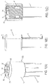
- figure 1 shows an endoscope head with pull cords according to an embodiment of the invention, wherein 1(A) a schematic perspective view, Fig.1(B) a side view and Fig.1(C) a sectional view along a line AA in Fig.1(B) demonstrate.
- figure 2 shows the endoscope head with pull cords according to the embodiment of FIG figure 1 , whereby Fig.2(A) a side view and Fig.2(B) a sectional view taken along a line DD in Fig.2(A) demonstrate.
- the endoscope shown has a deflecting section (also not shown) on a catheter section (not shown).
- the deflecting section extends from a ring member (not shown) on the proximal side of the deflecting section to an endoscope head 102 on the distal side of the deflecting section.
- the endoscope head 102 is thus arranged at a deflecting end of the endoscope.
- the endoscope head 102 has an MID (Molded Interconnected Device) molding 1 as an endoscope head body.
- the MID shaped element 1 is a plastic carrier made from an organic polymeric material, which can be produced, for example, by injection molding.
- the MID shaped element 1 consists of a thermoplastic or a duroplastic.
- the MID molded element 1 made of polypropylene (PP), acrylonitrile butadiene styrene (ABS), polycarbonate (PC), polyethylene terephthalate (PET), polybutylene terephthalate (PBT), polyamide (PA), polyphenylene sulfide (PPS), polysulfone (PSU), Polyethersulfone (PES), Polyetherimide (PEI), etc.
- PP polypropylene
- ABS acrylonitrile butadiene styrene
- PC polycarbonate
- PET polyethylene terephthalate
- PBT polybutylene terephthalate
- PA polyamide
- PPS polyphenylene sulfide
- PSU polysulfone
- PEI Polyetherimide
- the MID shaped member 1 is a cylinder-like member whose central axis extends from a proximal side to a distal side.
- the MID shaped element 1 can be connected to the deflecting section on the proximal side.
- the distal side of the MID shaped element 1 forms the distal side of the endoscope head 102.
- the MID shaped element 1 is surrounded by a cap 11 on the distal side and on the side surfaces.
- the cap 11 is a hollow cylinder provided with a base, the base of the cap forming the distal side of the endoscope head 102 when placed on the MID shaped element 1 .
- the cap 11 has such an inside diameter that it sits smoothly on the outside diameter of the MID shaped element 1 .
- a press fit can also be formed be.
- the cap 11 can have an internal thread on the inner peripheral surface and can be screwed onto an external thread on the MID shaped element 1 .
- Other positive connections between cap 11 and MID shaped element 1 are conceivable.
- the cap 11 On the distal end face, the cap 11 has distal openings 31 for signal output from an LED chip 3 described below, a distal opening for a camera window 61 for signal input for a camera 6 described below, a distal working channel opening 71 and distal flushing channel openings 71.
- the MID shaped element 1 projects beyond the cap 11 on the proximal side.
- a distal end section of a hose element (not shown) of the deflecting section is placed on the outer circumference of the MID shaped element 1 protruding proximally from the cap 11 .
- the distal end surface of the tube element is in sealing contact with the proximal end surface of the cap 11 .
- the distal end face of the tube member may be bonded to the proximal end face of the cap 11.
- FIG. 12 shows the MID shaped element 1 as the endoscope head body for the endoscope head according to the embodiment of FIG figure 1 .
- the MID shaped element 1 is provided with one or more metallic conductor tracks 21-28, 110, 111.
- the conductor tracks 21-28, 110, 111 can be applied to the MID shaped element 1 by two-component injection molding, by hot embossing, a mask exposure method, by laser structuring methods, by foil injection molding or another suitable method.
- the MID shaped element 1 provided with the conductor tracks 21-28, 110, 111 forms a three-dimensional printed circuit board.
- conductor tracks 21-28 for LED chips 3 described below and conductor tracks 110, 111 for a camera module 6 are formed on the MID shaped element 1.
- the MID shaped element 1 designed as a three-dimensional printed circuit board has several levels, which can be referred to as the first level for a traction cable anchoring body connection, the second level for a camera connection, the third level for an LED connection and the fourth level as the distal end surface.
- the first level and the second level can be offset from one another or can be at the same level.
- the MID shaped element 1 has indentations on its outer peripheral surface for the traction cable anchoring bodies 41 described below.
- Each of these indentations is of such a size that a traction cable anchoring body 41 can be accommodated in it and has a support surface area on its proximal side, on which the traction cable anchoring body is located 41 can be supported in the proximal direction.
- the support surface area thus extends horizontally, i.e. parallel to the proximal end surface of the MID mold element 1 and is located on the first plane described above.
- the indentations are adapted to the shape of the traction cable anchoring body 41 and are designed like a cylinder in the present example.
- the MID shaped element 1 has four such support surface areas.
- Each support surface area is provided centrally with a channel-like notch running to the proximal end surface of the MID shaped element 1, which receives the pull cable 4 connected to the pull cable anchoring body 41 when the pull cable anchoring body 41 is inserted in the support surface area.
- the diameter of the support surface area is in any case larger than the diameter of the traction cable 4. If, for example, a cuboid traction cable anchoring body is used and the indentation therefore has a cuboid shape, the result is a quadrangular support surface area.
- the support surface area is formed with a first conductor track 21 .
- a second conductor track 22 Connected to the conductor track 21 is a second conductor track 22, which initially extends vertically upwards formed at the edge of the bulge and extending horizontally away from the bulge on reaching the upper edge of the bulge and finally, as in figure 3 shown, merges into a third conductor track 23 extending vertically upwards.
- the third conductor track 23 is connected to a flat conductor track section 24 which is formed on the third level of the MID shaped element 1 .
- the planar conductor track section 24 forms an anode for a first LED chip 3 .
- the flat strip conductor section 25 forms a cathode for the first LED chip 3.
- the strip conductor sections 21-25 are shown in FIG figure 3 on the left side of a camera accommodation space provided above the second level for a camera connection. At the under consideration of figure 3 On the right side of the camera accommodating space, a wiring pattern similar to that on the left side is formed. In figure 3 on the right next to the second plane for a camera connection, an indentation for a traction cable anchoring body can be seen, which is also designed with a conductor track like the first conductor track 21 . This conductor track is connected to a flat conductor track section 26 on the third level.
- the planar conductor track section 26 forms a cathode for a second LED chip 3 .
- the planar conductor track section 27 forms an anode for the second LED chip 3.
- the planar conductor track section 25 is connected to the planar conductor track section 26 via a web 28, as is shown in FIG figure 3 is shown.
- the planar conductor track section 27 is connected to the planar conductor track section 24, which is shown in FIG figure 3 is not shown.
- Conductor track sections 110 are formed on the proximal side of the camera accommodation space, ie on the second level of the MID shaped element 1 , which lead to flat conductor track sections 111 for connecting a camera module 6 .
- the flat conductor track sections 111 are also shaped on the second level of the MID shaped element 1 .
- the trace portions 110 are electrically connected to a camera cable connector (not shown) provided on the proximal face of the MID mold element 1 . On this camera cable connector a supply cable is plugged in that is routed through the deflecting section.
- the MID shaped element 1 on the fourth level has a distal working channel opening 71 as an extension of a working channel element (not shown) for micro tools, for example, and at least one distal scavenging channel opening 81 of at least one scavenging channel.
- the MID shaped element 1 has two distal scavenging channel openings 81 for two scavenging channels. More specifically, in the MID mold 1 in the axial direction parallel to the central axis of the MID mold 1 in the area not occupied by the camera accommodating space and the wiring area, a working channel end portion and two scavenging channel end portions are provided as through holes.
- the working channel end section is arranged adjacent between the two scavenging channel end sections.
- the working channel end section On the distal end face of the MID shaped element 1, the working channel end section has the distal working channel opening 71 and the two scavenging channel end sections each have a distal scavenging channel opening 81.
- the working channel end section is arranged parallel and adjacent to the camera accommodation space.
- the scavenging channel end sections are arranged radially outside of the working channel end section, although the invention is not limited thereto.
- figure 4 shows an endoscope head body from figure 3 , in which traction cables are suspended.
- a traction cable anchoring body 41 is inserted into each lateral indentation on the MID shaped element 1 in such a way that its proximal side rests against the support surface area, so that a tensile force acting in the proximal direction is transmitted from the traction cable anchorage body 41 to the support surface area and thus to the MID shaped element 1.
- Each traction cable anchoring body 41 is fixed in a known manner at the distal end of a traction cable 4 .
- two lateral indentations on the MID shaped element 1 are provided with conductor tracks as described above.
- a traction cable anchoring body 41 with traction cable 4 is arranged in each case, which are electrically conductive.
- two of the four support surface areas are each lined with a conductor track section.
- Such a hawser anchor body 41 may have various shapes and may be a barrel nipple, a pear nipple, a ball nipple, etc.
- the MID shaped element 1 has four support surface areas for four traction cable anchoring bodies 41.
- the invention is not limited to this.
- the endoscope head 102 can have three, five or more traction cable anchoring bodies 41 and a corresponding number of support surface areas on the MID shaped element 1 .
- the endoscope head 102 can be pivoted in any desired direction in a known manner by means of a pulling movement on the pull cables 4 by a control element (not shown).
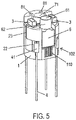
- figure 5 shows an endoscope head body from figure 4 , in which a camera module and LED chips are inserted.
- a first LED chip 3 is arranged on the flat conductor track section 24 (anode) and the flat conductor track section 25 (cathode).
- a second LED chip 3 is arranged on the conductor track section 26 (cathode) and the flat conductor track section 27 (anode).
- the LED chips 3 are arranged in such a way that their connections on the proximal side face the flat conductor track sections 24-27.
- the discharge surface of the LED chips 3 is on the distal side.
- the emission surface of the LED chips 3 is on a plane which is parallel and spaced apart from the distal end surface (fourth plane) of the MID mold element 1 . In other words, the distal end surface (fourth plane) of the MID mold element 1 protrudes in the distal direction beyond the discharge surface of the LED chips 3 .
- the camera module 6 is arranged in the camera accommodation space in such a way that the connection contacts 63 of the camera module 6 are in contact with the flat conductor track sections 111, see also Figure 2 (B) .
- the camera module 6 is arranged in such a way that its connection contacts on the proximal side face the flat conductor track sections 111 .
- a camera window 61 is arranged on the distal side, via which image information can be recorded. The distal end portion of the body of the camera module 6 extends to the camera window 61 and is surrounded by a cylindrical shield 62 .
- the shielding 62 extends in the distal direction beyond the distal end surface of the MID shaped element 1 and therefore protrudes slightly from the fourth plane of the MID shaped element 1 .
- the shielding 62 thus extends in the distal direction to beyond the horizontal plane of the emission surface of the LED chips 3. As a result, the shielding 62 shields the camera module 6 from the light radiation from the LED chips 3.
- the wall thickness of the distal end face of the cap 11 is selected to correspond to the height difference between the fourth plane of the MID mold element 1 and the distal end side of the shield 62 protruding from the fourth plane of the MID mold element 1 .
- a cavity 12 is therefore formed between the proximal inner surface of the distal end surface of the cap 11 and the third level of the MID shaped element 1, ie the level for the LED connection.
- This cavity 12 is delimited at the top by the cap 11 and (with the cap 11 in place) open only at the openings 31 on the distal side, see FIG Figure 1(C) .
- the openings 31 are each arranged exactly above the LED chips 3 .
- the cavity 12 can (but does not have to) be filled with a casting compound that covers the conductor track sections and LED chips 3 .
- the potting compound is transparent and curable and has sufficient adhesion to adhere to the bottom and walls of cavity 12.
- the MID shaped element 1 with the / the conductor tracks as a three-dimensional printed circuit board can be produced in various ways.
- a two-stage molding process can be used.
- a plastic carrier is injection molded as the base body of the MID shaped element 1 .
- the conductor track(s) are then applied to the base body, e.g. by two-component injection molding, hot embossing, mask exposure or laser structuring, etc.
- the MID shaped element 1 is designed in the manner of a cylinder with a small outer diameter in such a way that sufficient space is left for the working channel and the flushing channel(s).
- the cap 11 is placed on the MID shaped element 1 .
- the cap 11 can also be omitted.
- the outer surface and the distal end face of the MID shaped element 1 are shaped in such a way that they have no undercuts and can therefore be cleaned easily.
- the outer surface of the camera module 6 rests against the inner surface of the cap 11 .
- the MID shaped element 1 can also be shaped in such a way that a specific camera depression with a distal opening is provided in the MID shaped element 1, into which the camera module 6 is inserted from the distal side. The side surfaces of the camera module 6 are then surrounded by the MID shaped element 1, with the exception of the distal side.
- the specific camera recess can be dimensioned to fit the camera module 6 precisely.
- the camera shielding 62 protruding from the MID shaped element 1 on the distal side can be snapped into place on the proximal side in the MID shaped element 1 in order to give the camera module 6 a secure hold in the MID shaped element 1 and at the same time be easy to remove.
- the camera module 6 is firmly cast on the MID shaped element 1 using a casting compound.
- the MID mold member 1 can be formed to have a peripheral wall up to the height of the fourth plane. Then the sealing compound forms an end surface on the distal side, which forms the distal end surface of the endoscope head.
- the distal end surface of the casting compound is curved inward, but in a further example it can also be flat, ie even.
- the top surface of the transparent and hardened casting compound on the distal side of the MID shaped element is therefore curved inwards or extends flat. An outwardly directed curvature of the distal end face of the casting compound is also possible.
- the shielding extends in the distal direction beyond the distal end surface of the MID shaped element 1 and protrudes slightly from the fourth plane of the MID shaped element 1 of the distal end surface of the casting compound.
- a working channel section and two scavenging channel sections extend parallel to and at a distance from the central axis of the MID shaped element 1.
- the working channel section can also be arranged on the central axis of the MID shaped element 1.
- Three or more flushing channels can be provided. However, because of the small size, a design with one or two flushing channels is preferable.
- the working channel section and/or the scavenging channels can run obliquely in the MID shaped element 1 .
- a camera module 6 as an optical sensor is arranged on the MID mold element 1, and LED chips 3 are provided as optical signal generators as an example of an electronic instrument.
- LED chips 3 an ultrasonic emitting device can be used as the electronic instrument, and an acoustic sensor can be arranged instead of the camera module 6, the acoustic sensor being shielded from the cavity.
- the shielding wall portions protruding from the distal end face of the molding compound may be omitted.
Landscapes
- Health & Medical Sciences (AREA)
- Life Sciences & Earth Sciences (AREA)
- Surgery (AREA)
- Engineering & Computer Science (AREA)
- Physics & Mathematics (AREA)
- Biomedical Technology (AREA)
- Animal Behavior & Ethology (AREA)
- Radiology & Medical Imaging (AREA)
- Optics & Photonics (AREA)
- Nuclear Medicine, Radiotherapy & Molecular Imaging (AREA)
- Biophysics (AREA)
- Heart & Thoracic Surgery (AREA)
- Medical Informatics (AREA)
- Molecular Biology (AREA)
- Pathology (AREA)
- General Health & Medical Sciences (AREA)
- Public Health (AREA)
- Veterinary Medicine (AREA)
- Manufacturing & Machinery (AREA)
- Microelectronics & Electronic Packaging (AREA)
- Endoscopes (AREA)
- Instruments For Viewing The Inside Of Hollow Bodies (AREA)
- Ultra Sonic Daignosis Equipment (AREA)
Description
- Die vorliegende Erfindung bezieht sich auf einen Endoskopkopf und auf ein mit diesem versehenes Endoskop. Genauer gesagt bezieht sich die vorliegende Erfindung auf einen verbesserten Endoskopkopf, der am distalen Ende eines Deflectingabschnittes eines Endoskops einsetzbar ist.
- In der Endoskopie geht der Trend seit geraumer Zeit hin zu immer kleineren Endoskopen. In diesem Zusammenhang wird auch ein Endoskopkopf, der am distalen Ende eines Deflectingabschnittes eines Endoskops angeordnet ist, immer kleiner gestaltet. Dabei wird es immer schwieriger, die in der Endoskopie genutzten Einrichtungen wie z.B. LED, Kamera und/oder Arbeitskanal etc. im Endoskopkopf zu integrieren.
- Die
WO 2013/129 204 A1 offenbart einen Endoskopabschnitt an einem Teil eines Endoskops. Der Endoskopabschnitt hat Leiterbahnen, die über Kabel mit Strom versorgt werden können. - Die
EP 1 030 607 A1 offenbart ein Endoskop mit einem Zugseil zum Handhaben von abzutrennenden Gewebeteilen durch Ziehen und Transportieren von Energie. - Die vorliegende Erfindung soll einen neuen Weg aufzeigen, wie durch innovative Gestaltung eines Endoskopkopfes eine weitere Miniaturisierung von Endoskopen und Endoskopköpfen möglich wird.
- Somit ist es eine Aufgabe der vorliegenden Erfindung, einen verbesserten Endoskopkopf zu schaffen. Darüber hinaus soll ein verbessertes Endoskop geschaffen werden.
- Im Hinblick auf den Endoskopkopf ist die Aufgabe durch einen Endoskopkopf gemäß Anspruch 1 gelöst.
- Im Hinblick auf das Endoskop ist die Aufgabe durch ein Endoskop gemäß Anspruch 5 gelöst. Vorteilhafte Weiterbildungen sind Gegenstand der abhängigen Ansprüche.
- Die vorliegende Offenbarung betrifft einen Endoskopkopf an einem Deflectingende eines Endoskops, mit einem Endoskopkopfkörper mit zumindest einer an diesem aufgetragenen Leiterbahn; zumindest einem elektronischen Instrument, das im Endoskopkopfkörper sitzt und durch dessen zumindest eine Leiterbahn elektrisch versorgbar ist; und zumindest einem Zugseil, dessen Zugseilverankerung im Endoskopkopfkörper sitzt; wobei das zumindest eine Zugseil mit der zumindest einen Leiterbahn des Endoskopkopfkörpers elektrisch in Verbindung steht.
- Dadurch ergibt sich eine kostengünstig gestaltete elektrische Versorgung des Endoskopkopfes bei platzsparender Ausführung. Auf ein Raum benötigendes elektrisches Versorgungskabel für das elektronische Instrument kann verzichtet werden.
- Im Endoskopkopf kann das zumindest eine Zugseil über seine Zugseilverankerung mit der zumindest einen Leiterbahn des Endoskopkopfkörpers elektrisch in Verbindung stehen. Die Zugseilverankerung kann ein elektrisch leitfähiger Körper sein, der die Leiterbahn und das Zugseil elektrisch verbindet.
- Im Endoskopkopf können am Endoskopkopfkörper vier Zugseile verankert sein, von denen zwei Zugseile mit der zumindest einen Leiterbahn des Endoskopkopfkörpers elektrisch in Verbindung stehen. Von den vier Zugseilen können zwei Zugseile elektrisch leitfähig sein. Die Funktionsweise ist die gleiche wie bei einem herkömmlichen Endoskopkopf, bei dem mittels vier Zugseilen die Auslenkbewegung gesteuert wird. Es können auch alle vier Zugseile elektrisch leitfähig sein.
- Die Anzahl an Zugseilen ist nicht eingeschränkt.
- Der Endoskopkopfkörper kann ein MID-Formelement sein.
- Der Endoskopkopfkörper ist dadurch kostengünstig und umweltverträglich herstellbar, kann vielseitig und mit hoher Gestaltungsfreiheit geformt werden. Beliebige Endoskopkopfkörperformen sind daher möglich. Eine weitere Miniaturisierung der Endoskopkopfe wird verwirklicht. Die Anzahl an verwendeten Materialen zur Herstellung des Endoskopkopfkörpers ist auf ein Minimum beschränkt, was zu einer Material- und Teilezahleinsparung führt. Die Anzahl an Montageschritten wird verringert. Die Genauigkeit der Formgebung und damit auch die Zuverlässigkeit des Endoskopkopfes werden drastisch erhöht. Für den Endoskopkopfkörper können im Gegensatz zu herkömmlichen Leiterplatten unproblematisch entsorgbare Materialien eingesetzt werden. Die axiale Länge des Endoskopkopfkörpers kann verkürzt werden.
- Nachstehend sind Ausführungsbeispiele der Erfindung detailliert anhand von Beispielen erläutert.
-
-
Figur 1 zeigt einen Endoskopkopf mit Zugseilen gemäß einem Ausführungsbeispiel der Erfindung, wobeiFig. 1(A) eine schematische perspektivische Ansicht, -
Fig. 1(B) eine Seitenansicht undFig. 1(C) eine Schnittansicht entlang einer Linie A-A inFig. 1(B) zeigen. -
Figur 2 zeigt den Endoskopkopf mit Zugseilen gemäß dem Ausführungsbeispiel vonFigur 1 , wobeiFig. 2(A) eine Seitenansicht undFig. 2(B) eine Schnittansicht entlang einer Linie D-D inFig. 2(A) zeigen. -
Figur 3 zeigt einen Endoskopkopfkörper für den Endoskopkopf gemäß dem Ausführungsbeispiel vonFigur 1 . -
Figur 4 zeigt einen Endoskopkopfkörper vonFigur 3 , in den Zugseile eingehängt sind. -
Figur 5 zeigt einen Endoskopkopfkörper vonFigur 4 , in den ein Kameramodul und LED-Chips eingesetzt ist. - Nachstehend ist die vorliegenden Erfindung detailliert anhand der Zeichnungen beschrieben.
-
Figur 1 zeigt einen Endoskopkopf mit Zugseilen gemäß einem Ausführungsbeispiel der Erfindung, wobeiFig. 1(A) eine schematische perspektivische Ansicht,Fig. 1(B) eine Seitenansicht undFig. 1(C) eine Schnittansicht entlang einer Linie A-A inFig. 1(B) zeigen.Figur 2 zeigt den Endoskopkopf mit Zugseilen gemäß dem Ausführungsbeispiel vonFigur 1 , wobeiFig. 2(A) eine Seitenansicht undFig. 2(B) eine Schnittansicht entlang einer Linie D-D inFig. 2(A) zeigen. - Das dargestellte Endoskop weist an einem (nicht gezeigten) Katheterabschnitt einen Deflectingabschnitt (ebenfalls nicht gezeigt) auf. Der Deflectingabschnitt erstreckt sich von einem (nicht gezeigten) Ringelement an der proximalen Seite des Deflectingabschnittes zu einem Endoskopkopf 102 an der distalen Seite des Deflectingabschnittes. Der Endoskopkopf 102 ist somit an einem Deflectingende des Endoskops angeordnet.
- Der Endoskopkopf 102 weist ein MID-Formelement (molded interconnected device) 1 als Endoskopkopfkörper auf. Das MID-Formelement 1 ist ein Kunststoffträger aus einem organischen polymeren Material, der z.B. durch Spritzgießen herstellbar ist. Beispielsweise besteht das MID-Formelement 1 aus einem Thermoplast oder einem Duroplast. Insbesondere kann das MID-Formelement 1 aus Polypropylen (PP), Acrylnitryl-Butadienstyrol (ABS), Polycarbonat (PC), Polyethylenterephtalat (PET), Polybutylenterephtalat (PBT), Polyamid (PA), Polyphenylensulfid (PPS), Polysulfon (PSU), Polyethersulfon (PES), Polyetherimid (PEI), etc hergestellt werden. Diese Angaben sind lediglich Beispiele und weitere Materialen können für das MID-Formelement 1 verwendet werden.
- Das MID-Formelement 1 ist ein zylinderartiges Element, dessen Mittelachse sich von einer proximalen Seite zu einer distalen Seite erstreckt. An der proximalen Seite ist das MID-Formelement 1 an den Deflectingabschnitt verbindbar. Die distale Seite des MID-Formelementes 1 bildet die distale Seite des Endoskopkopfes 102.
- An der distalen Seite und an den Seitenflächen ist das MID-Formelement 1 von einer Kappe 11 umgeben. Die Kappe 11 ist ein mit einem Boden versehener Hohlzylinder, wobei der Boden der Kappe im am MID-Formelement 1 aufgesetzten Zustand die distale Seite des Endoskopkopfes 102 bildet. Die Kappe 11 hat einen solchen Innendurchmesser, dass sie leichtgängig am Außendurchmesser des MID-Formelementes 1 sitzt. Alternativ kann auch eine Presspassung ausgebildet sein. In einer weiteren Alternative kann die Kappe 11 an der Innenumfangsfläche ein Innengewinde aufweisen und auf ein Außengewinde am MID-Formelement 1 aufgeschraubt werden. Weitere formschlüssige Verbindungen zwischen Kappe 11 und MID-Formelement 1 sind denkbar.
- An der distalen Stirnfläche besitzt die Kappe 11 distale Öffnungen 31 für eine Signalausgabe eines nachstehend beschriebenen LED-Chips 3, eine distale Öffnung für ein Kamerafenster 61 für eine Signaleingabe für eine nachstehend beschriebene Kamera 6, eine distale Arbeitskanalöffnung 71 und distale Spülkanalöffnungen 71.
- Im am MID-Formelement 1 aufgesetzten Zustand der Kappe 11 ragt das MID-Formelement 1 an der proximalen Seite über die Kappe 11 vor. An dem aus der Kappe 11 proximal vorragenden Außenumfang des MID-Formelementes 1 wird ein distaler Endabschnitt eines nicht gezeigten Schlauchelementes des Deflectingabschnittes aufgesetzt. Die distale Stirnfläche des Schlauchelementes liegt an der proximalen Endfläche der Kappe 11 abgedichtet an. Die distale Stirnfläche des Schlauchelementes kann mit der proximalen Endfläche der Kappe 11 verklebt sein.
-
Figur 3 zeigt das MID-Formelement 1 als den Endoskopkopfkörper für den Endoskopkopf gemäß dem Ausführungsbeispiel vonFigur 1 . - Das MID-Formelement 1 ist mit einer oder mehreren metallischen Leiterbahnen 21-28, 110, 111 versehen. Die Leiterbahnen 21-28, 110, 111 können am MID-Formelement 1 durch Zweikomponentenspritzguss, durch Heißprägen, ein Maskenbelichtungsverfahren, durch Laserstrukturierverfahren, durch Folienhinterspritzen oder ein anderes geeignetes Verfahren aufgetragen werden. Im Prinzip bildet das mit der/den Leiterbahnen 21-28, 110, 111 versehene MID-Formelement 1 eine dreidimensionale Leiterplatte.
- Genauer gesagt sind am MID-Formelement 1 Leiterbahnen 21-28 für nachstehend beschriebene LED-Chips 3 und Leiterbahnen 110, 111 für ein Kameramodul 6 angeformt.
- Nachstehend sind die Leiterbahnen genauer beschrieben.
- Unter Betrachtung von
Figur 3 besitzt das als dreidimensionale Leiterplatte ausgebildete MID-Formelement 1 mehrere Ebenen, die als erste Ebene für einen Zugseilverankerungskörperanschluss, zweite Ebene für einen Kameraanschluss, dritte Ebene für einen LED-Anschluss und vierte Ebene als distale Endfläche bezeichnet werden können. Die erste Ebene und die zweite Ebene können zueinander versetzt sein oder auf gleicher Höhe liegen. - Beabstandet zur proximalen Endfläche besitzt das MID-Formelement 1 an seiner Außenumfangsfläche jeweilige Einbauchungen für nachstehend beschriebene Zugseilverankerungskörper 41. Jede dieser Einbauchungen hat eine derartige Größe, dass ein Zugseilverankerungskörper 41 darin Platz findet, besitzt an ihrer proximalen Seite einen Abstützflächenbereich, an dem sich der Zugseilverankerungskörper 41 in proximaler Richtung abstützen kann. Der Abstützflächenbereich erstreckt sich somit horizontal d.h. parallel zur proximalen Endfläche des MID-Formelements 1 und befindet sich an der vorstehend beschriebenen ersten Ebene. Die Einbauchungen sind an die Form des Zugseilverankerungskörpers 41 angepasst und sind im vorliegenden Beispiel zylinderartig gestaltet. Somit hat im vorliegenden Beispiel das MID-Formelement 1 vier solche Abstützflächenbereiche. Jeder Abstützflächenbereich ist zentrisch mit einer zur proximalen Endfläche des MID-Formelements 1 laufenden rinnenartigen Einkerbung versehen, die bei am Abstützflächenbereich eingesetzten Zugseilverankerungskörper 41 das mit dem Zugseilverankerungskörper 41 verbundene Zugseil 4 aufnimmt. Der Durchmesser des Abstützflächenbereiches ist auf jeden Fall größer als der Durchmesser des Zugseils 4. Sollte z.B. ein quaderartiger Zugseilverankerungskörper angewendet werden und die Einbauchung daher eine quaderartige Form haben, ergibt sich ein viereckiger Abstützflächenbereich.
- Zumindest für zwei Zugseilverankerungskörper (in
Figur 3 an den beiden dem Betrachter zugewandten Einbauchungen) ist der Abstützflächenbereich mit einer ersten Leiterbahn 21 ausgeformt. Mit der Leiterbahn 21 ist jeweils eine sich zunächst senkrecht nach oben erstreckende zweite Leiterbahn 22 verbunden, die am Rand der Einbauchung angeformt ist und sich bei Erreichen des oberen Randes der Einbauchung horizontal von der Einbauchung weg erstreckt und schließlich, wie inFigur 3 gezeigt, in eine sich senkrecht nach oben erstreckende dritte Leiterbahn 23 übergeht. Die dritte Leiterbahn 23 ist mit einem flächigen Leiterbahnabschnitt 24 verbunden, der an der dritten Ebene des MID-Formelements 1 angeformt ist. Der flächige Leiterbahnabschnitt 24 bildet eine Anode für einen ersten LED-Chip 3. Benachbart und kontaktfrei zum flächige Leiterbahnabschnitt 24 ist ein flächiger Leiterbahnabschnitt 25 an der dritten Ebene des MID-Formelements 1 angeformt. Der flächige Leiterbahnabschnitt 25 bildet eine Kathode für den ersten LED-Chip 3. Die Leiterbahneabschnitte 21-25 befinden sich unter Betrachtung vonFigur 3 an der linken Seite eines oberhalb der zweiten Ebene für einen Kameraanschluss vorgesehenen Kameraunterbringungsraums. An der unter Betrachtung vonFigur 3 rechten Seite des Kameraunterbringungsraums ist eine ähnliche Leiterbahnstruktur wie an der linken Seite ausgebildet. InFigur 3 ist rechts neben der zweiten Ebene für einen Kameraanschluss eine Einbauchung für einen Zugseilverankerungskörper erkennbar, die ebenfalls mit einer Leiterbahn wie die erste Leiterbahn 21 ausgebildet ist. Diese Leiterbahn ist mit einem flächigen Leiterbahnabschnitt 26 an der dritten Ebene verbunden. Der flächige Leiterbahnabschnitt 26 bildet eine Kathode für einen zweiten LED-Chip 3. Benachbart und kontaktfrei zum flächigen Leiterbahnabschnitt 26 ist ein flächiger Leiterbahnabschnitt 27 an der dritten Ebene des MID-Formelements 1 angeformt. Der flächige Leiterbahnabschnitt 27 bildet eine Anode für den zweiten LED-Chip 3. Der flächige Leiterbahnabschnitt 25 ist über einen Steg 28 mit dem flächigen Leiterbahnabschnitt 26 verbunden, wie dies inFigur 3 gezeigt ist. Der flächige Leiterbahnabschnitt 27 ist mit dem flächigen Leiterbahnabschnitt 24 verbunden, was in der Darstellung vonFigur 3 nicht gezeigt ist. - An der proximalen Seite des Kameraunterbringungsraums, d.h. auf der zweiten Ebene des MID-Formelements 1 sind Leiterbahnabschnitte 110 ausgeformt, die in flächige Leiterbahnabschnitte 111 für einen Anschluss eines Kameramoduls 6 münden. Die flächigen Leiterbahnabschnitte 111 sind auch auf der zweiten Ebene des MID-Formelements 1 ausgeformt. Die Leiterbahnabschnitte 110 sind mit einem (nicht gezeigten) Kamerakabelanschluss elektrisch verbunden, der an der proximalen Fläche des MID-Formelements 1 vorgesehen ist. An diesem Kamerakabelanschluss ist ein Versorgungskabel eingesteckt, dass im Deflectingabschnitt geführt ist.
- Außerdem weist das MID-Formelement 1 an der vierten Ebene eine distale Arbeitskanalöffnung 71 als Verlängerung eines nicht gezeigten Arbeitskanalelementes für z.B. Mikrowerkzeuge und zumindest eine distale Spülkanalöffnung 81 zumindest eines Spülkanals auf. Im vorliegenden Beispiel weist das MID-Formelement 1 zwei distale Spülkanalöffnungen 81 für zwei Spülkanale auf. Genauer gesagt sind im MID-Formelement 1 in axialer Richtung parallel zur Mittelachse des MID-Formelementes 1 in dem Bereich, der nicht von dem Kameraunterbringungsraum und dem Leiterbahnenbereich eingenommen wird, ein Arbeitskanalendabschnitt und zwei Spülkanalendabschnitte als Durchgangslöcher vorgesehen. Wie in
Fig. 1 gezeigt, ist der Arbeitskanalendabschnitt zwischen den beiden Spülkanalendabschnitten benachbart angeordnet. An der distalen Stirnfläche des MID-Formelementes 1 hat der Arbeitskanalendabschnitt die distale Arbeitskanalöffnung 71 und haben die beiden Spülkanalendabschnitte jeweils eine distale Spülkanalöffnung 81. Der Arbeitskanalendabschnitt ist dabei parallel und benachbart zu dem Kameraunterbringungsraum angeordnet. Die Spülkanalendabschnitte sind radial außerhalb des Arbeitskanalendabschnitt angeordnet, wobei die Erfindung nicht darauf beschränkt ist. - Nachstehend ist der weitere Aufbau des Endoskopkopfes 102 detailliert erläutert.
Figur 4 zeigt einen Endoskopkopfkörper vonFigur 3 , in den Zugseile eingehängt sind. - In jede seitliche Einbauchung am MID-Formelement 1 ist ein Zugseilverankerungskörper 41 so eingesetzt, dass seine proximalen Seite am Abstützflächenbereich anliegt, so dass eine in proximaler Richtung wirkende Zugkraft vom Zugseilverankerungskörper 41 auf den Abstützflächenbereich und somit auf das MID-Formelement 1 übertragen wird. Jeder Zugseilverankerungskörper 41 ist am distalen Ende eines Zugseils 4 in bekannter Weise fest angeordnet.
- Im vorliegenden Beispiel sind zwei seitliche Einbauchung am MID-Formelement 1 wie vorstehend beschrieben mit Leiterbahnen versehen. In diese Einbauchungen ist jeweils ein Zugseilverankerungskörper 41 mit Zugseil 4 angeordnet, die elektrisch leitfähig sind. Im vorliegenden Beispiel sind zwei der vier Abstützflächenbereiche mit jeweils einem Leiterbahnabschnitt ausgekleidet.
- Die beiden in
Figur 4 vorderen Zugseilverankerungskörper 41, die jeweils an einem Leiterbahnabschnitt 2 sitzen, und die mit ihnen verbundenen Zugseile 4 sind elektrisch leitfähig. Jeder Leiterbahnabschnitt 2, an dem ein elektrisch leitfähiger Zugseilverankerungskörper 41 sitzt, bildet einen elektrischen Anschluss für ein elektronisches Instrument. Somit können die Leiterbahnabschnitte 21-28 über die elektrisch leitfähigen Zugseile 4 mit elektrischem Strom versorgt werden. Eine Gleichspannungsversorgung oder eine Wechselspannungsversorgung des elektronischen Instruments oder der elektronischen Instrumente sind dadurch möglich. Im vorliegenden Beispiel vonFig. 1 sind am MID-Formelement vier Zugseile 4 verankert, von denen zwei Zugseile 4 mit der zumindest einen Leiterbahn 2 des MID-Formelementes 1 elektrisch in Verbindung stehen. - Ein solcher Zugseilverankerungskörper 41 kann verschiedene Formen haben und kann ein Tonnennippel, ein Birnennippel, ein Kugelnippel etc. sein.
- Im vorliegenden Beispiel hat das MID-Formelement 1 vier Abstützflächenbereiche für vier Zugseilverankerungskörper 41. Die Erfindung ist nicht darauf beschränkt. Der Endoskopkopf 102 kann drei, fünf oder mehr Zugseilverankerungskörper 41 und in entsprechender Anzahl Abstützflächenbereiche am MID-Formelement 1 aufweisen.
- Der Endoskopkopf 102 kann anhand einer Zugbewegung an den Zugseilen 4 durch ein nicht gezeigtes Steuerelement in eine beliebige Richtung in bekannter Weise geschwenkt werden.
-
Figur 5 zeigt einen Endoskopkopfkörper vonFigur 4 , in den ein Kameramodul und LED-Chips eingesetzt ist. - Auf dem flächigen Leiterbahnabschnitt 24 (Anode) und dem flächigen Leiterbahnabschnitt 25 (Kathode) ist ein erster LED-Chip 3 angeordnet. Auf dem flächigen Leiterbahnabschnitt 26 (Kathode) und dem flächigen Leiterbahnabschnitt 27 (Anode) ist ein zweiter LED-Chip 3 angeordnet. Insbesondere sind die LED-Chips 3 so angeordnet, dass ihre Anschlüsse an der proximalen Seite den flächigen Leiterbahnabschnitten 24-27 zugewandt sind. Die Abgabefläche der LED-Chips 3 befindet sich an deren distaler Seite. Die Abgabefläche der LED-Chips 3 befindet sich auf einer Ebene die parallel und beabstandet zur distalen Endfläche (vierte Ebene) des MID-Formelementes 1 ist. Anders ausgedrückt ragt die zur distalen Endfläche (vierte Ebene) des MID-Formelementes 1 in distaler Richtung über die Abgabefläche der LED-Chips 3 vor.
- In den Kameraunterbringungsraum ist das Kameramodul 6 so angeordnet, dass die Anschlusskontakte 63 des Kameramoduls 6 mit den flächigen Leiterbahnabschnitten 111 in Kontakt stehen, siehe auch
Figur 2 (B) . Insbesondere ist das Kameramodul 6 so angeordnet, dass seine Anschlusskontakte an der proximalen Seite den flächigen Leiterbahnabschnitten 111 zugewandt sind. An der distalen Seite ist ein Kamerafenster 61 angeordnet, über das Bildinformationen aufgenommen werden können. Der distale Endbereich des Körpers des Kameramoduls 6 erstreckt sich bis zu dem Kamerafenster 61 und ist von einer zylindrischen Abschirmung 62 umgeben. - Die Abschirmung 62 erstreckt sich in distaler Richtung bis über die distale Endfläche des MID-Formelementes 1 hinaus und ragt also von der vierten Ebene des MID-Formelementes 1 geringfügig vor. Die Abschirmung 62 erstreckt sich somit in distaler Richtung bis über die die horizontale Ebene der Abgabefläche der LED-Chips 3. Dadurch wird durch die Abschirmung 62 eine Abschirmung des Kameramoduls 6 vor der Lichtstrahlung der LED-Chips 3 geschaffen.
- Die Wandstärke der distalen Endfläche der Kappe 11 ist so gewählt, dass sie der Höhendifferenz zwischen der vierten Ebene des MID-Formelementes 1 und der distalen Endseite der von der vierten Ebene des MID-Formelementes 1 vorragenden Abschirmung 62 entspricht. Somit liegt bei auf dem MID-Formelement 1 aufgesetzter Kappe 11 die proximale Innenfläche der distalen Endfläche der Kappe 11 an der vierten Ebene des MID-Formelementes 1 an, und die distale Endseite der Abschirmung 62 ist in etwas fluchtend zur distalen Außenfläche der distalen Endfläche der Kappe 11.
- Zwischen der proximalen Innenfläche der distalen Endfläche der Kappe 11 und der dritten Ebene des MID-Formelementes 1, d.h. der Ebene für den LED-Anschluss, ist daher ein Hohlraum 12 gebildet. Dieser Hohlraum 12 ist an der Oberseite durch die Kappe 11 begrenzt und (bei aufgesetzter Kappe 11) nur an den Öffnungen 31 an der distalen Seite offen, siehe
Figur 1(C) . Die Öffnungen 31 sind jeweils genau oberhalb der LED-Chips 3 angeordnet. - Der Hohlraum 12 kann (aber muß nicht) mit einer Vergussmasse ausgefüllt sein, die die Leiterbahnabschnitte und LED-Chips 3 bedeckt. Die Vergussmasse ist transparent und aushärtbar und besitzt ein ausreichendes Haftungsvermögen für ein Anhaften am Boden und den Wänden des Hohlraums 12.
- Das MID-Formelement 1 mit der/den Leiterbahnen als dreidimensionale Leiterplatte kann auf verschiedene Weise hergestellt werden.
- Beispielsweise kann ein Zweistufenformverfahren angewendet werden.
- Zunächst wird ein Kunststoffträger als Grundkörper des MID-Formelementes 1 spritzgegossen. Danach werden die Leiterbahn(en) auf dem Grundkörper z.B. durch Zweikomponentenspritzguss, Heißprägen, Maskenbelichtung oder Laserstrukturierung etc. aufgetragen.
- Die Formgebung ist dabei weitgehend frei wählbar. Als Endoskopkopfkörper wird das MID-Formelement 1 zylinderartig mit einem kleinen Außendurchmesser so gestaltet, dass ausreichend Platz für den Arbeitskanal und den/die Spülkanäle belassen bleibt.
- Im vorliegenden Beispiel der
Figuren 1-5 sind am MID-Formelement 1 vier Zugseile 4 verankert, von denen zwei Zugseile 4 mit der zumindest einen Leiterbahn 2 des MID-Formelementes 1 elektrisch in Verbindung stehen. Die Erfindung ist aber auch auf ein MID-Formelement 1 anwendbar, bei dem kein Zugseil 4 elektrisch leitfähig ist. Die elektrische Versorgung der Leiterbahn 2 wird dann über im Deflectingabschnitt 100 verlaufende Kabel bewerkstelligt. - Im vorliegenden Beispiel ist die Kappe 11 auf das MID-Formelement 1 aufgesetzt. Die Kappe 11 kann auch weggelassen werden. In diesem Fall wird die Außenfläche und die distale Stirnfläche des MID-Formelement 1 so geformt, dass sie keine Hinterschneidungen aufweist und daher gut gereinigt werden kann.
- Im vorliegenden Beispiel der
Figuren 1-5 liegt die Außenfläche des Kameramoduls 6 an der Innenfläche der Kappe 11 an. Das MID-Formelement 1 kann auch so geformt sein, dass im MID-Formelement 1 eine spezifische Kameravertiefung mit distaler Öffnung vorgesehen ist, in die das Kameramodul 6 von der distalen Seite eingeschoben wird. Die Seitenflächen des Kameramoduls 6 sind dann mit Ausnahme an der distalen Seite von dem MID-Formelement 1 umgeben. Die spezifische Kameravertiefung kann passgenau für das Kameramodul 6 bemessen sein. Die an der distalen Seite von dem MID-Formelement 1 vorragende Kameraabschirmung 62 kann an der proximalen Seite im MID-Formelement 1 einrastbar sein, um dem Kameramodul 6 im MID-Formelement 1 sicheren Halt zu geben und gleichzeitig leicht entnehmbar zu sein. Alternativ ist das Kameramodul 6 am MID-Formelement 1 durch eine Vergussmasse fest angegossen. - Bei weggelassener Kappe 11 kann das MID-Formelement 1 so ausgebildet sein, dass es eine umlaufende Wand bis zu der Höhe der vierten Ebene hat. Dann bildet die Vergussmasse an der distalen Seite eine Endfläche, die die distale Endfläche des Endoskopkopfes bildet. Die distale Endfläche der Vergussmasse ist nach innen gewölbt ausgebildet kann aber in einem weiteren Bespiel auch flach d.h. eben sein. Die Deckfläche der transparenten und ausgehärteten Vergussmasse an der distalen Seite des MID-Formelementes ist also nach innen gewölbt oder erstreckt sich plan. Auch eine nach außen gerichtete Wölbung der distalen Endfläche der Vergussmasse ist möglich. Am distalen Ende des MID-Formelementes 1 ist somit ebenfalls ein Raum wie der Hohlraum 12 vorhanden, in dem zumindest ein elektronisches Instrument 3 auf einer Leiterbahn 2 des MID-Formelementes 1 sitzt, wobei dieser Raum durch die transparente und ausgehärtete Vergussmasse gefüllt ist. Die Abschirmung erstreckt sich auch in diesem Fall in distaler Richtung bis über die distale Endfläche des MID-Formelementes 1 und ragt von der vierte Ebene des MID-Formelementes 1 der distalen Endfläche der Vergussmasse geringfügig vor.
- Im MID-Formelement 1 erstreckt sich ein Arbeitskanalabschnitt und zwei Spülkanalabschnitte parallel und beabstandet zur Mittelachse des MID-Formelementes 1. Der Arbeitskanalabschnitt kann auch auf der Mittelachse des MID-Formelementes 1 angeordnet sein. Es können drei oder mehr Spülkanäle vorgesehen sein. Jedoch ist des kleines Aufbaus wegen eine Konstruktion mit einem oder zwei Spülkanälen zu bevorzugen. Der Arbeitskanalabschnitt und/oder die Spülkanäle kann/können in einer weiteren Alternative im MID-Formelement 1 schräg verlaufen.
- Im vorliegenden Beispiel ist ein Kameramodul 6 als ein optischer Sensor am MID-Formelement 1 angeordnet, und sind LED-Chips 3 als optische Signalgeber als ein Beispiel für ein elektronisches Instrument vorgesehen. Alternativ kann anstelle der LED-Chips 3 als elektronisches Instrument eine Ultraschallemittiereinrichtung sein, und anstelle des Kameramoduls 6 kann ein Akustiksensor angeordnet sein, wobei der Akustiksensor zum Hohlraum hin abgeschirmt ist.
- Wenn der Sensorbereich für eine andere Sensorart genutzt wird, wie z.B. ein akustischer Sensor, können die von der distalen Endfläche der Vergussmasse vorragenden Abschirmungswandabschnitte auch weggelassen werden.
-
- 1 MID-Formelement
- 11 Kappe
- 12 Hohlraum
- 21-28, 110, 111 Leiterbahn
- 3 LED-Chip
- 31 Öffnung
- 4 Zugseil
- 41 Zugseilverankerungskörper
- 6 Kameramodul
- 61 Kamerafenster
- 62 Kameraabschirmung
- 63 Kameraanschlusskontakte
- 7 Arbeitskanalelement
- 71 distale Arbeitskanalöffnung
- 8 Spülkanal
- 81 distale Spülkanalöffnung
- 102 Endoskopkopf
- 110 Leiterbahnabschnitte
- 111 Leiterbahnabschnitte für Anschluss des Kameramoduls
Claims (5)
- Endoskopkopf (102) an einem Deflectingende eines Endoskops, miteinem Endoskopkopfkörper (1) mit zumindest einer an diesem aufgetragenen Leiterbahn (21-28);zumindest einem elektronischen Instrument (3), das im Endoskopkopfkörper (1) sitzt und durch dessen zumindest eine Leiterbahn (21-28) elektrisch versorgbar ist; undzumindest einem Zugseil (4), dessen Zugseilverankerung (41) im Endoskopkopfkörper (1) sitzt, wobei der Endoskopkopf (102) so aufgebaut ist, dass der Endoskopkopf (102) anhand einer Zugbewegung am Zugseil (4) geschwenkt werden kann;wobei das zumindest eine Zugseil (4) mit der zumindest einen Leiterbahn (21-28) des Endoskopkopfkörpers (1) elektrisch in Verbindung steht.
- Endoskopkopf (102) gemäß Anspruch 1,
das zumindest eine Zugseil (4) über seine Zugseilverankerung (41) mit der zumindest einen Leiterbahn (21-28) des Endoskopkopfkörpers (1) elektrisch in Verbindung steht. - Endoskopkopf (102) gemäß Anspruch 1 oder 2, wobei
am Endoskopkopfkörper (1) vier Zugseile (4) verankert sind, von denen zwei Zugseile mit der zumindest einen Leiterbahn (21-28) des Endoskopkopfkörpers (1) elektrisch in Verbindung stehen. - Endoskopkopf (102) gemäß einem der Ansprüche 1 bis 3, wobei
der Endoskopkopfkörper ein MID-Formelement (1) ist. - Endoskop mit einem Endoskopkopf (102) gemäß einem der Ansprüche 1 bis 4.
Applications Claiming Priority (2)
| Application Number | Priority Date | Filing Date | Title |
|---|---|---|---|
| DE102013224683.8A DE102013224683A1 (de) | 2013-12-02 | 2013-12-02 | Endoskopkopf und endoskop |
| PCT/EP2014/075902 WO2015082328A1 (de) | 2013-12-02 | 2014-11-28 | Endoskopkopf und endoskop |
Publications (2)
| Publication Number | Publication Date |
|---|---|
| EP3076851A1 EP3076851A1 (de) | 2016-10-12 |
| EP3076851B1 true EP3076851B1 (de) | 2022-08-03 |
Family
ID=52003751
Family Applications (1)
| Application Number | Title | Priority Date | Filing Date |
|---|---|---|---|
| EP14806228.4A Active EP3076851B1 (de) | 2013-12-02 | 2014-11-28 | Endoskopkopf und endoskop |
Country Status (6)
| Country | Link |
|---|---|
| US (1) | US10939803B2 (de) |
| EP (1) | EP3076851B1 (de) |
| JP (1) | JP6533787B2 (de) |
| CN (1) | CN106061350B (de) |
| DE (1) | DE102013224683A1 (de) |
| WO (1) | WO2015082328A1 (de) |
Families Citing this family (43)
| Publication number | Priority date | Publication date | Assignee | Title |
|---|---|---|---|---|
| US10849483B2 (en) * | 2014-09-15 | 2020-12-01 | Vivid Medical, Inc. | Single-use, port deployable articulating endoscope |
| DE102015113016B4 (de) | 2015-08-07 | 2018-03-29 | Digital Endoscopy Gmbh | Endoskopkopf |
| DE102017107106A1 (de) | 2017-04-03 | 2018-10-04 | Hoya Corporation | Endoskop mit weitwinkeloptik und arbeitskanal |
| DE102017107978B4 (de) | 2017-04-12 | 2019-01-10 | Konstantin Bob | Endoskopkopf mit schwenkbarer Kamera- und Arbeitskanal-Einheit |
| US10485950B2 (en) * | 2017-08-03 | 2019-11-26 | ART MEDICAL Ltd. | Multipurpose cabling |
| CN107822580A (zh) * | 2017-10-20 | 2018-03-23 | 上海安清医疗器械有限公司 | 一种蜂巢结构的先端头部、内窥镜及其制造方法 |
| CN107802230B (zh) * | 2017-11-21 | 2023-09-26 | 江苏西铭医药有限公司 | 一种内窥镜用可调向套管组件及内窥镜装置 |
| AU2019294724B2 (en) | 2018-06-28 | 2024-10-24 | Boston Scientific Scimed, Inc. | Encapsulated components of medical devices, and methods therefor |
| CN109717820B (zh) * | 2018-12-07 | 2024-06-07 | 上海英诺伟医疗器械股份有限公司 | 基于柔性管的体内探测装置与系统 |
| JPWO2020121435A1 (ja) * | 2018-12-12 | 2021-09-30 | オリンパス株式会社 | 内視鏡の先端部および内視鏡 |
| WO2020129165A1 (ja) * | 2018-12-18 | 2020-06-25 | オリンパス株式会社 | 内視鏡先端構造、および内視鏡 |
| CN109700432B (zh) * | 2018-12-21 | 2024-06-07 | 上海英诺伟医疗器械股份有限公司 | 基于柔性管的探测封装结构与体内探测装置 |
| DE112019006478B4 (de) * | 2018-12-28 | 2023-11-16 | Hoya Corporation | Endoskop und Endoskopsystem |
| DE102019100395B4 (de) | 2019-01-09 | 2025-06-26 | Olympus Winter & Ibe Gmbh | Verbindungskörper eines Endoskops und Verfahren zum Montieren eines Endoskops |
| TWI733074B (zh) * | 2019-01-09 | 2021-07-11 | 榮晶生物科技股份有限公司 | 微型電子裝置及其電路基板 |
| WO2020170340A1 (ja) * | 2019-02-19 | 2020-08-27 | オリンパス株式会社 | 内視鏡先端構造、および内視鏡 |
| DE102019105671A1 (de) * | 2019-03-06 | 2020-09-10 | Hoya Corporation | Endoskop mit Lichtabstrahleinrichtung und Bildaufnahmeeinrichtung am distalen Endabschnitt |
| WO2020188688A1 (ja) | 2019-03-18 | 2020-09-24 | オリンパス株式会社 | 内視鏡の先端ユニット |
| WO2020188687A1 (ja) * | 2019-03-18 | 2020-09-24 | オリンパス株式会社 | 内視鏡の先端枠及び先端ユニット |
| WO2020188685A1 (ja) | 2019-03-18 | 2020-09-24 | オリンパス株式会社 | 内視鏡の先端ユニット |
| CN113329676B (zh) * | 2019-03-18 | 2024-05-24 | 奥林巴斯株式会社 | 保持框、内窥镜前端构造以及内窥镜 |
| WO2020194726A1 (ja) | 2019-03-28 | 2020-10-01 | オリンパス株式会社 | 内視鏡の先端枠及び先端ユニット |
| CN113350653B (zh) * | 2020-03-04 | 2025-11-21 | 南微医学科技股份有限公司 | 一种多功能导管 |
| WO2021181528A1 (ja) * | 2020-03-10 | 2021-09-16 | オリンパス株式会社 | 内視鏡、内視鏡の先端枠部材および内視鏡の挿入部 |
| JP7245956B2 (ja) * | 2020-03-10 | 2023-03-24 | オリンパス株式会社 | 内視鏡、内視鏡の先端枠部材および内視鏡の挿入部 |
| WO2021181530A1 (ja) * | 2020-03-10 | 2021-09-16 | オリンパス株式会社 | 内視鏡、内視鏡の先端枠部材および内視鏡の挿入部 |
| US12268368B2 (en) | 2020-04-30 | 2025-04-08 | Ambu A/S | Medical visualisation device |
| US11931066B2 (en) * | 2021-02-25 | 2024-03-19 | Avent, Inc. | Directly connected smart invasive medical device assembly |
| WO2022204311A1 (en) * | 2021-03-24 | 2022-09-29 | PacificMD Biotech, LLC | Endoscope and endoscope sheath with diagnostic and therapeutic interfaces |
| CN117377420A (zh) | 2021-06-03 | 2024-01-09 | 奥林巴斯医疗株式会社 | 摄像单元和内窥镜 |
| WO2022269901A1 (ja) | 2021-06-25 | 2022-12-29 | オリンパスメディカルシステムズ株式会社 | 撮像ユニット、内視鏡、および、撮像ユニットの製造方法 |
| CN117320610A (zh) | 2021-06-29 | 2023-12-29 | 奥林巴斯医疗株式会社 | 摄像单元、内窥镜以及摄像单元的制造方法 |
| WO2023017598A1 (ja) | 2021-08-12 | 2023-02-16 | オリンパスメディカルシステムズ株式会社 | 撮像ユニットと、この撮像ユニットを適用する内視鏡 |
| CN117678072A (zh) * | 2021-08-19 | 2024-03-08 | 奥林巴斯株式会社 | 摄像模块、内窥镜及摄像模块的制造方法 |
| CN114052829B (zh) * | 2021-10-11 | 2023-12-19 | 武汉威润八方医疗科技有限公司 | 输尿管取石装置 |
| US11963667B2 (en) * | 2021-11-26 | 2024-04-23 | Altek Biotechnology Corporation | Endoscopic image capturing assembly and endoscopic device therewith |
| US12551094B2 (en) * | 2021-11-26 | 2026-02-17 | Altek Biotechnology Corporation | Endoscopic image capturing assembly and endoscopic device therewith |
| WO2024004150A1 (ja) * | 2022-06-30 | 2024-01-04 | ジェイソル・メディカル株式会社 | 電子ユニット |
| TWI836767B (zh) * | 2022-12-02 | 2024-03-21 | 群光電子股份有限公司 | 內視鏡模組 |
| CN121568634A (zh) * | 2023-08-07 | 2026-02-24 | 波士顿科学医学有限公司 | 用于医疗装置的电子组件 |
| JP7717236B1 (ja) | 2024-01-19 | 2025-08-01 | オリンパスメディカルシステムズ株式会社 | 内視鏡、撮像モジュール、および、内視鏡の製造方法 |
| WO2026043706A1 (en) * | 2024-08-21 | 2026-02-26 | Boston Scientific Scimed, Inc. | Medical devices, systems, and methods |
| DE102024134028A1 (de) * | 2024-11-20 | 2026-05-21 | Karl Storz Se & Co. Kg | Zerlegung und Entsorgung eines medizinischen Instruments |
Citations (1)
| Publication number | Priority date | Publication date | Assignee | Title |
|---|---|---|---|---|
| EP1030607A1 (de) * | 1997-11-13 | 2000-08-30 | Boston Scientific Limited | Vorrichtung sowie verfahren zum abtrennen von läsionen |
Family Cites Families (85)
| Publication number | Priority date | Publication date | Assignee | Title |
|---|---|---|---|---|
| US3549806A (en) | 1967-05-05 | 1970-12-22 | Gen Electric | Fundamental pitch frequency signal extraction system for complex signals |
| US3605725A (en) | 1968-08-07 | 1971-09-20 | Medi Tech Inc | Controlled motion devices |
| DE6905185U (de) | 1969-02-11 | 1972-04-06 | Bowden Controls Ltd | Bowdenzug. |
| JPS4827116B1 (de) | 1969-09-12 | 1973-08-18 | ||
| JPS6121041Y2 (de) | 1977-08-04 | 1986-06-24 | ||
| JPS5939128B2 (ja) | 1979-10-31 | 1984-09-21 | オリンパス光学工業株式会社 | 内視鏡 |
| JPS57110228A (en) | 1980-12-26 | 1982-07-09 | Olympus Optical Co | Air and water sending switch apparatus of endoscope |
| US4415767A (en) | 1981-10-19 | 1983-11-15 | Votan | Method and apparatus for speech recognition and reproduction |
| JPS60148536A (ja) | 1984-01-17 | 1985-08-05 | オリンパス光学工業株式会社 | 内視鏡 |
| EP0161834B1 (de) | 1984-05-04 | 1988-01-07 | Warner-Lambert Technologies, Inc. | Objektivsystem für Endoskope |
| JPS61118713A (ja) * | 1984-11-14 | 1986-06-06 | Olympus Optical Co Ltd | 内視鏡 |
| US4670009A (en) | 1985-04-16 | 1987-06-02 | American Hospital Supply Corp. | Backform inserts for catheter |
| JPS62227312A (ja) | 1986-03-27 | 1987-10-06 | 旭光学工業株式会社 | 内視鏡の湾曲操作ワイヤの取付構造 |
| US5245133A (en) | 1991-10-15 | 1993-09-14 | Thomas & Betts Corporation | Moisture-resistant cable splice and sealing structure thereof |
| JP3219521B2 (ja) | 1993-03-01 | 2001-10-15 | オリンパス光学工業株式会社 | 内視鏡 |
| US5569157A (en) | 1993-05-07 | 1996-10-29 | Olympus Optical Co., Ltd. | Endoscope |
| US5588950A (en) | 1994-07-11 | 1996-12-31 | Asahi Kogaku Kogyo Kabushiki Kaisha | Portable endoscope system |
| US5630419A (en) | 1994-12-20 | 1997-05-20 | Tetrad Corporation | Sealing connector for multiconductor cables |
| DE19627016C1 (de) | 1996-07-04 | 1998-02-12 | Etm Endotech Gmbh Medizintechn | Flexibles Endoskop |
| US5845241A (en) | 1996-09-04 | 1998-12-01 | Hughes Electronics Corporation | High-accuracy, low-distortion time-frequency analysis of signals using rotated-window spectrograms |
| JPH10225439A (ja) | 1997-02-17 | 1998-08-25 | Olympus Optical Co Ltd | 内視鏡用撮像装置 |
| DE19731965A1 (de) | 1997-07-24 | 1999-01-28 | Etm Endotech Gmbh Medizintechn | Luft/Wasser- und Absaugventile an Endoskopen |
| DE19840986A1 (de) | 1998-09-08 | 2000-03-09 | Etm Endoskopische Technik Gmbh | Schnellverschluss für ein Endoskop |
| DE19843337A1 (de) | 1998-09-22 | 2000-03-23 | Sram De Gmbh | Justiereinrichtung für Betätigungszüge zum Steuern von Fahrradgetrieben |
| US6734893B1 (en) | 1998-12-04 | 2004-05-11 | Olympus Winter & Ibe Gmbh | Endoscopy illumination system for stroboscopy |
| JP3179426B2 (ja) * | 1998-12-21 | 2001-06-25 | オリンパス光学工業株式会社 | 内視鏡装置 |
| US6547722B1 (en) | 1999-07-13 | 2003-04-15 | Olympus Optical Co., Ltd. | Endoscope having resistance to high-temperature and high-pressure steam |
| JP2001061772A (ja) | 1999-08-30 | 2001-03-13 | Fuji Photo Optical Co Ltd | 内視鏡の流体制御装置 |
| JP3488170B2 (ja) | 2000-03-21 | 2004-01-19 | オリンパス株式会社 | 内視鏡 |
| JP3821206B2 (ja) | 2000-09-29 | 2006-09-13 | フジノン株式会社 | 内視鏡のコネクタ用防水キャップ |
| JP2002160691A (ja) | 2000-11-28 | 2002-06-04 | Nissin Kogyo Co Ltd | バーハンドル車両用ブレーキ装置 |
| JP2002238831A (ja) | 2001-02-16 | 2002-08-27 | Fuji Photo Optical Co Ltd | 内視鏡 |
| JP2002291699A (ja) | 2001-03-30 | 2002-10-08 | Asahi Optical Co Ltd | 声帯観察用の内視鏡システム |
| US20060199999A1 (en) | 2001-06-29 | 2006-09-07 | Intuitive Surgical Inc. | Cardiac tissue ablation instrument with flexible wrist |
| US6793622B2 (en) | 2001-09-05 | 2004-09-21 | Olympus Optical Co., Ltd. | Electric bending endoscope |
| JP2003190085A (ja) | 2001-12-25 | 2003-07-08 | Olympus Optical Co Ltd | 電気的コネクタ |
| JP2007111541A (ja) | 2002-05-29 | 2007-05-10 | Olympus Corp | 内視鏡装置と内視鏡用接続装置 |
| JP2004049891A (ja) | 2002-05-29 | 2004-02-19 | Olympus Corp | 内視鏡装置 |
| US7179223B2 (en) | 2002-08-06 | 2007-02-20 | Olympus Optical Co., Ltd. | Endoscope apparatus having an internal channel |
| DE10254609B4 (de) * | 2002-11-22 | 2017-12-07 | Stm Medizintechnik Starnberg Gmbh | Endoskopkopf |
| DE10320228A1 (de) | 2003-05-05 | 2004-11-25 | Stm Medizintechnik Starnberg Gmbh | Endoskopschaft |
| JP2005006769A (ja) * | 2003-06-17 | 2005-01-13 | Olympus Corp | カプセル内視鏡 |
| US7842028B2 (en) | 2005-04-14 | 2010-11-30 | Cambridge Endoscopic Devices, Inc. | Surgical instrument guide device |
| JP4461100B2 (ja) | 2004-02-16 | 2010-05-12 | オリンパス株式会社 | 内視鏡システム |
| AU2005228956B2 (en) | 2004-03-23 | 2011-08-18 | Boston Scientific Limited | In-vivo visualization system |
| JP2005304586A (ja) | 2004-04-19 | 2005-11-04 | Pentax Corp | 側方視型内視鏡の先端部 |
| US7811277B2 (en) * | 2004-09-30 | 2010-10-12 | Boston Scientific Scimed, Inc. | Steerable device and system |
| JP4661190B2 (ja) | 2004-11-30 | 2011-03-30 | 富士フイルム株式会社 | 洗浄アダプタ |
| CN2762381Y (zh) | 2004-12-17 | 2006-03-01 | 亮泰企业股份有限公司 | 交流电源插头及插座的防水结构 |
| US20060252993A1 (en) | 2005-03-23 | 2006-11-09 | Freed David I | Medical devices and systems |
| EP1886617A4 (de) | 2005-05-26 | 2010-09-29 | Ars Co Ltd | Endoskopvorrichtung |
| WO2007002526A1 (en) | 2005-06-24 | 2007-01-04 | Everest Vit, Inc. | Insertion tube storage carousel |
| DE102005041454A1 (de) | 2005-08-31 | 2007-03-01 | Karl Storz Gmbh & Co. Kg | Endoskop |
| AU2007201204B2 (en) | 2006-03-23 | 2012-07-12 | Ethicon Endo-Surgery, Inc. | Articulating endoscopic accessory channel |
| US20070225562A1 (en) | 2006-03-23 | 2007-09-27 | Ethicon Endo-Surgery, Inc. | Articulating endoscopic accessory channel |
| JP4812515B2 (ja) | 2006-05-26 | 2011-11-09 | 富士フイルム株式会社 | 洗浄アダプタ |
| US7615067B2 (en) | 2006-06-05 | 2009-11-10 | Cambridge Endoscopic Devices, Inc. | Surgical instrument |
| JP2008119057A (ja) | 2006-11-08 | 2008-05-29 | Matsushita Electric Works Ltd | カプセル型撮像装置 |
| KR200444134Y1 (ko) | 2007-07-09 | 2009-04-10 | 유메디칼 주식회사 | 음성신호를 이용한 후두 스트로보스코프 |
| ES2356497T3 (es) | 2007-08-23 | 2011-04-08 | Tyco Healthcare Group Lp | Dispositivos quirúrgicos endoscópicos. |
| US9005238B2 (en) | 2007-08-23 | 2015-04-14 | Covidien Lp | Endoscopic surgical devices |
| JP2009201762A (ja) | 2008-02-28 | 2009-09-10 | Hoya Corp | 内視鏡および撮影モジュール |
| EP2119390B1 (de) | 2008-05-16 | 2011-07-20 | FUJIFILM Corporation | Anschlussstück für Endoskop |
| CN102307510B (zh) * | 2008-12-10 | 2014-10-08 | 阿姆布股份有限公司 | 具有照相机壳体的内窥镜及制造照相机壳体的方法 |
| US8700129B2 (en) | 2008-12-31 | 2014-04-15 | St. Jude Medical, Atrial Fibrillation Division, Inc. | Devices and methods for catheter localization |
| US8512371B2 (en) * | 2009-10-06 | 2013-08-20 | Covidien Lp | Jaw, blade and gap manufacturing for surgical instruments with small jaws |
| DE102009060500B4 (de) | 2009-12-22 | 2015-12-17 | Xion Gmbh | Verfahren zur stroboskopischen Untersuchung sich wiederholender Vorgänge und Anordnung zum Betreiben dieses Verfahrens |
| WO2011108157A1 (ja) | 2010-03-05 | 2011-09-09 | オリンパスメディカルシステムズ株式会社 | 内視鏡 |
| CN102791182A (zh) | 2010-03-16 | 2012-11-21 | 奥林巴斯医疗株式会社 | 连接器座、连接器连接系统、光源装置和内窥镜 |
| TW201201641A (en) | 2010-06-18 | 2012-01-01 | Sun Wei Ren | Micro sensor |
| DE102010034623A1 (de) | 2010-08-17 | 2012-02-23 | Olympus Winter & Ibe Gmbh | Endoskop mit Videokamera im Schaftkörper |
| DE102010039731A1 (de) | 2010-08-25 | 2012-03-01 | Olympus Winter & Ibe Gmbh | Elektrisches Verbindungselement und Endoskopiesystem |
| JP5552014B2 (ja) | 2010-09-29 | 2014-07-16 | 富士フイルム株式会社 | 内視鏡の吸引ボタン |
| CN102665525B (zh) | 2010-12-24 | 2013-09-25 | 奥林巴斯株式会社 | 内窥镜装置 |
| EP2659656B1 (de) | 2010-12-29 | 2018-07-18 | Skype | Dynamische anpassung von datencodierung abhänig der cpu-last |
| DE102012100933A1 (de) | 2011-02-04 | 2012-08-09 | Schott Ag | Haftsystem, seine Herstellung und Anwendungen |
| JP5851118B2 (ja) | 2011-05-25 | 2016-02-03 | オリンパス株式会社 | 内視鏡装置 |
| EP2740397B1 (de) | 2011-08-03 | 2017-09-27 | Olympus Corporation | Drahtzugmechanismus und endoskopische vorrichtung |
| CN102401995B (zh) | 2011-11-18 | 2013-05-29 | 无锡微奥科技有限公司 | 一种内窥镜微型光学探头 |
| JP5883683B2 (ja) * | 2012-03-02 | 2016-03-15 | Hoya株式会社 | 光走査型内視鏡 |
| CN202748535U (zh) | 2012-08-16 | 2013-02-20 | 宁波舜宇光电信息有限公司 | 工业用内窥镜 |
| EP2878272A4 (de) | 2012-09-05 | 2016-04-20 | Olympus Corp | Ultraschallendoskop |
| US9549666B2 (en) * | 2012-11-10 | 2017-01-24 | Curvo Medical, Inc. | Coaxial micro-endoscope |
| CN103211566B (zh) | 2013-04-17 | 2014-12-10 | 杭州安杰思医学科技有限公司 | 具有注水注气选择按钮的内窥镜 |
| CN105473048B (zh) | 2013-08-20 | 2017-10-27 | 库克医学技术有限责任公司 | 可安装内窥镜的可视化装置和手柄 |
-
2013
- 2013-12-02 DE DE102013224683.8A patent/DE102013224683A1/de not_active Withdrawn
-
2014
- 2014-11-28 EP EP14806228.4A patent/EP3076851B1/de active Active
- 2014-11-28 JP JP2016536635A patent/JP6533787B2/ja active Active
- 2014-11-28 US US15/101,391 patent/US10939803B2/en active Active
- 2014-11-28 WO PCT/EP2014/075902 patent/WO2015082328A1/de not_active Ceased
- 2014-11-28 CN CN201480074685.2A patent/CN106061350B/zh active Active
Patent Citations (1)
| Publication number | Priority date | Publication date | Assignee | Title |
|---|---|---|---|---|
| EP1030607A1 (de) * | 1997-11-13 | 2000-08-30 | Boston Scientific Limited | Vorrichtung sowie verfahren zum abtrennen von läsionen |
Also Published As
| Publication number | Publication date |
|---|---|
| EP3076851A1 (de) | 2016-10-12 |
| US20170127915A1 (en) | 2017-05-11 |
| CN106061350A (zh) | 2016-10-26 |
| JP6533787B2 (ja) | 2019-06-19 |
| DE102013224683A1 (de) | 2015-06-03 |
| JP2017505154A (ja) | 2017-02-16 |
| WO2015082328A1 (de) | 2015-06-11 |
| CN106061350B (zh) | 2019-10-29 |
| US10939803B2 (en) | 2021-03-09 |
Similar Documents
| Publication | Publication Date | Title |
|---|---|---|
| EP3076851A1 (de) | Endoskopkopf und endoskop | |
| EP1659780B1 (de) | Bildaufnehmermodul sowie Verfahren zum Zusammenbauen eines Bildaufnehmermoduls | |
| DE19924189C2 (de) | Bildaufnehmermodul sowie Verfahren zum Zusammenbauen eines derartigen Bildaufnehmermoduls | |
| EP1484950B1 (de) | Elektrisches Kontaktierungsverfahren | |
| EP2606273B1 (de) | Gehäustes led-modul | |
| DE102007012818B4 (de) | Halbleitervorrichtung mit Anschlüssen | |
| EP2784373B1 (de) | Biegbarer LED-Streifen | |
| DE102010002580A1 (de) | Stecker, LED-Einheit und Verfahren zum Herstellen des Steckers | |
| EP2018043A1 (de) | Bildaufnehmermodul | |
| DE102019112685A1 (de) | Leuchte mit geschützt gelagerten Leuchtmitteln | |
| EP2265102B1 (de) | Sensoraufbau ohne Gehäuse | |
| EP2819492A1 (de) | MID-Bauteil, Verfahren zur Herstellung | |
| EP2730952B1 (de) | Lichtgitter | |
| DE102009012538B4 (de) | Lichtschranke und Verfahren zur Herstellung einer Lichtschranke | |
| EP3597018B1 (de) | Elektronisches steuermodul und verfahren zum herstellen eines elektronischen steuermoduls | |
| DE102008033205A1 (de) | Bauelementhalter zur Befestigung eines elektronischen Bauelements | |
| WO2015185167A1 (de) | Baustein, baustein-anordnung und verfahren zum herstellen eines bausteins | |
| DE102018118478B4 (de) | Verfahren zur Herstellung einer beleuchtbaren Baugruppe und beleuchtbare Baugruppe | |
| DE102010041121A1 (de) | Schaltungsträger sowie Verfahren zur Herstellung eines Schaltungsträgers | |
| DE10106478B4 (de) | Magnetische Längenmessvorrichtung | |
| EP3408865B1 (de) | Bauelementträger mit kontaktkammern für eine optoelektronische vorrichtung | |
| DE19901913A1 (de) | Elektrisches Gerät mit einem Gehäuse | |
| DE20309009U1 (de) | Elektrisches Bauteil, insbesondere Positionssensor | |
| DE102013017229A1 (de) | LED-Streifen sowie Steckerelement | |
| EP4054825B1 (de) | Verfahren zur herstellung eines funktionsbauteil-pakets |
Legal Events
| Date | Code | Title | Description |
|---|---|---|---|
| PUAI | Public reference made under article 153(3) epc to a published international application that has entered the european phase |
Free format text: ORIGINAL CODE: 0009012 |
|
| 17P | Request for examination filed |
Effective date: 20160614 |
|
| AK | Designated contracting states |
Kind code of ref document: A1 Designated state(s): AL AT BE BG CH CY CZ DE DK EE ES FI FR GB GR HR HU IE IS IT LI LT LU LV MC MK MT NL NO PL PT RO RS SE SI SK SM TR |
|
| AX | Request for extension of the european patent |
Extension state: BA ME |
|
| DAX | Request for extension of the european patent (deleted) | ||
| STAA | Information on the status of an ep patent application or granted ep patent |
Free format text: STATUS: EXAMINATION IS IN PROGRESS |
|
| 17Q | First examination report despatched |
Effective date: 20200206 |
|
| GRAP | Despatch of communication of intention to grant a patent |
Free format text: ORIGINAL CODE: EPIDOSNIGR1 |
|
| STAA | Information on the status of an ep patent application or granted ep patent |
Free format text: STATUS: GRANT OF PATENT IS INTENDED |
|
| INTG | Intention to grant announced |
Effective date: 20220503 |
|
| GRAS | Grant fee paid |
Free format text: ORIGINAL CODE: EPIDOSNIGR3 |
|
| GRAA | (expected) grant |
Free format text: ORIGINAL CODE: 0009210 |
|
| STAA | Information on the status of an ep patent application or granted ep patent |
Free format text: STATUS: THE PATENT HAS BEEN GRANTED |
|
| AK | Designated contracting states |
Kind code of ref document: B1 Designated state(s): AL AT BE BG CH CY CZ DE DK EE ES FI FR GB GR HR HU IE IS IT LI LT LU LV MC MK MT NL NO PL PT RO RS SE SI SK SM TR |
|
| REG | Reference to a national code |
Ref country code: AT Ref legal event code: REF Ref document number: 1508086 Country of ref document: AT Kind code of ref document: T Effective date: 20220815 Ref country code: CH Ref legal event code: EP |
|
| REG | Reference to a national code |
Ref country code: DE Ref legal event code: R096 Ref document number: 502014016341 Country of ref document: DE |
|
| REG | Reference to a national code |
Ref country code: IE Ref legal event code: FG4D Free format text: LANGUAGE OF EP DOCUMENT: GERMAN |
|
| REG | Reference to a national code |
Ref country code: LT Ref legal event code: MG9D |
|
| REG | Reference to a national code |
Ref country code: NL Ref legal event code: MP Effective date: 20220803 |
|
| PG25 | Lapsed in a contracting state [announced via postgrant information from national office to epo] |
Ref country code: SE Free format text: LAPSE BECAUSE OF FAILURE TO SUBMIT A TRANSLATION OF THE DESCRIPTION OR TO PAY THE FEE WITHIN THE PRESCRIBED TIME-LIMIT Effective date: 20220803 Ref country code: RS Free format text: LAPSE BECAUSE OF FAILURE TO SUBMIT A TRANSLATION OF THE DESCRIPTION OR TO PAY THE FEE WITHIN THE PRESCRIBED TIME-LIMIT Effective date: 20220803 Ref country code: PT Free format text: LAPSE BECAUSE OF FAILURE TO SUBMIT A TRANSLATION OF THE DESCRIPTION OR TO PAY THE FEE WITHIN THE PRESCRIBED TIME-LIMIT Effective date: 20221205 Ref country code: NO Free format text: LAPSE BECAUSE OF FAILURE TO SUBMIT A TRANSLATION OF THE DESCRIPTION OR TO PAY THE FEE WITHIN THE PRESCRIBED TIME-LIMIT Effective date: 20221103 Ref country code: NL Free format text: LAPSE BECAUSE OF FAILURE TO SUBMIT A TRANSLATION OF THE DESCRIPTION OR TO PAY THE FEE WITHIN THE PRESCRIBED TIME-LIMIT Effective date: 20220803 Ref country code: LV Free format text: LAPSE BECAUSE OF FAILURE TO SUBMIT A TRANSLATION OF THE DESCRIPTION OR TO PAY THE FEE WITHIN THE PRESCRIBED TIME-LIMIT Effective date: 20220803 Ref country code: LT Free format text: LAPSE BECAUSE OF FAILURE TO SUBMIT A TRANSLATION OF THE DESCRIPTION OR TO PAY THE FEE WITHIN THE PRESCRIBED TIME-LIMIT Effective date: 20220803 Ref country code: FI Free format text: LAPSE BECAUSE OF FAILURE TO SUBMIT A TRANSLATION OF THE DESCRIPTION OR TO PAY THE FEE WITHIN THE PRESCRIBED TIME-LIMIT Effective date: 20220803 Ref country code: ES Free format text: LAPSE BECAUSE OF FAILURE TO SUBMIT A TRANSLATION OF THE DESCRIPTION OR TO PAY THE FEE WITHIN THE PRESCRIBED TIME-LIMIT Effective date: 20220803 |
|
| PG25 | Lapsed in a contracting state [announced via postgrant information from national office to epo] |
Ref country code: PL Free format text: LAPSE BECAUSE OF FAILURE TO SUBMIT A TRANSLATION OF THE DESCRIPTION OR TO PAY THE FEE WITHIN THE PRESCRIBED TIME-LIMIT Effective date: 20220803 Ref country code: IS Free format text: LAPSE BECAUSE OF FAILURE TO SUBMIT A TRANSLATION OF THE DESCRIPTION OR TO PAY THE FEE WITHIN THE PRESCRIBED TIME-LIMIT Effective date: 20221203 Ref country code: HR Free format text: LAPSE BECAUSE OF FAILURE TO SUBMIT A TRANSLATION OF THE DESCRIPTION OR TO PAY THE FEE WITHIN THE PRESCRIBED TIME-LIMIT Effective date: 20220803 Ref country code: GR Free format text: LAPSE BECAUSE OF FAILURE TO SUBMIT A TRANSLATION OF THE DESCRIPTION OR TO PAY THE FEE WITHIN THE PRESCRIBED TIME-LIMIT Effective date: 20221104 |
|
| PG25 | Lapsed in a contracting state [announced via postgrant information from national office to epo] |
Ref country code: SM Free format text: LAPSE BECAUSE OF FAILURE TO SUBMIT A TRANSLATION OF THE DESCRIPTION OR TO PAY THE FEE WITHIN THE PRESCRIBED TIME-LIMIT Effective date: 20220803 Ref country code: RO Free format text: LAPSE BECAUSE OF FAILURE TO SUBMIT A TRANSLATION OF THE DESCRIPTION OR TO PAY THE FEE WITHIN THE PRESCRIBED TIME-LIMIT Effective date: 20220803 Ref country code: DK Free format text: LAPSE BECAUSE OF FAILURE TO SUBMIT A TRANSLATION OF THE DESCRIPTION OR TO PAY THE FEE WITHIN THE PRESCRIBED TIME-LIMIT Effective date: 20220803 Ref country code: CZ Free format text: LAPSE BECAUSE OF FAILURE TO SUBMIT A TRANSLATION OF THE DESCRIPTION OR TO PAY THE FEE WITHIN THE PRESCRIBED TIME-LIMIT Effective date: 20220803 |
|
| REG | Reference to a national code |
Ref country code: DE Ref legal event code: R097 Ref document number: 502014016341 Country of ref document: DE |
|
| PG25 | Lapsed in a contracting state [announced via postgrant information from national office to epo] |
Ref country code: SK Free format text: LAPSE BECAUSE OF FAILURE TO SUBMIT A TRANSLATION OF THE DESCRIPTION OR TO PAY THE FEE WITHIN THE PRESCRIBED TIME-LIMIT Effective date: 20220803 Ref country code: EE Free format text: LAPSE BECAUSE OF FAILURE TO SUBMIT A TRANSLATION OF THE DESCRIPTION OR TO PAY THE FEE WITHIN THE PRESCRIBED TIME-LIMIT Effective date: 20220803 |
|
| PLBE | No opposition filed within time limit |
Free format text: ORIGINAL CODE: 0009261 |
|
| STAA | Information on the status of an ep patent application or granted ep patent |
Free format text: STATUS: NO OPPOSITION FILED WITHIN TIME LIMIT |
|
| PG25 | Lapsed in a contracting state [announced via postgrant information from national office to epo] |
Ref country code: MC Free format text: LAPSE BECAUSE OF FAILURE TO SUBMIT A TRANSLATION OF THE DESCRIPTION OR TO PAY THE FEE WITHIN THE PRESCRIBED TIME-LIMIT Effective date: 20220803 Ref country code: AL Free format text: LAPSE BECAUSE OF FAILURE TO SUBMIT A TRANSLATION OF THE DESCRIPTION OR TO PAY THE FEE WITHIN THE PRESCRIBED TIME-LIMIT Effective date: 20220803 |
|
| REG | Reference to a national code |
Ref country code: CH Ref legal event code: PL |
|
| 26N | No opposition filed |
Effective date: 20230504 |
|
| REG | Reference to a national code |
Ref country code: BE Ref legal event code: MM Effective date: 20221130 |
|
| PG25 | Lapsed in a contracting state [announced via postgrant information from national office to epo] |
Ref country code: LI Free format text: LAPSE BECAUSE OF NON-PAYMENT OF DUE FEES Effective date: 20221130 Ref country code: CH Free format text: LAPSE BECAUSE OF NON-PAYMENT OF DUE FEES Effective date: 20221130 |
|
| PG25 | Lapsed in a contracting state [announced via postgrant information from national office to epo] |
Ref country code: SI Free format text: LAPSE BECAUSE OF FAILURE TO SUBMIT A TRANSLATION OF THE DESCRIPTION OR TO PAY THE FEE WITHIN THE PRESCRIBED TIME-LIMIT Effective date: 20220803 Ref country code: LU Free format text: LAPSE BECAUSE OF NON-PAYMENT OF DUE FEES Effective date: 20221128 |
|
| PG25 | Lapsed in a contracting state [announced via postgrant information from national office to epo] |
Ref country code: IE Free format text: LAPSE BECAUSE OF NON-PAYMENT OF DUE FEES Effective date: 20221128 |
|
| PG25 | Lapsed in a contracting state [announced via postgrant information from national office to epo] |
Ref country code: BE Free format text: LAPSE BECAUSE OF NON-PAYMENT OF DUE FEES Effective date: 20221130 |
|
| REG | Reference to a national code |
Ref country code: AT Ref legal event code: MM01 Ref document number: 1508086 Country of ref document: AT Kind code of ref document: T Effective date: 20221128 |
|
| PG25 | Lapsed in a contracting state [announced via postgrant information from national office to epo] |
Ref country code: AT Free format text: LAPSE BECAUSE OF NON-PAYMENT OF DUE FEES Effective date: 20221128 |
|
| PG25 | Lapsed in a contracting state [announced via postgrant information from national office to epo] |
Ref country code: HU Free format text: LAPSE BECAUSE OF FAILURE TO SUBMIT A TRANSLATION OF THE DESCRIPTION OR TO PAY THE FEE WITHIN THE PRESCRIBED TIME-LIMIT; INVALID AB INITIO Effective date: 20141128 |
|
| PG25 | Lapsed in a contracting state [announced via postgrant information from national office to epo] |
Ref country code: CY Free format text: LAPSE BECAUSE OF FAILURE TO SUBMIT A TRANSLATION OF THE DESCRIPTION OR TO PAY THE FEE WITHIN THE PRESCRIBED TIME-LIMIT Effective date: 20220803 |
|
| PG25 | Lapsed in a contracting state [announced via postgrant information from national office to epo] |
Ref country code: MK Free format text: LAPSE BECAUSE OF FAILURE TO SUBMIT A TRANSLATION OF THE DESCRIPTION OR TO PAY THE FEE WITHIN THE PRESCRIBED TIME-LIMIT Effective date: 20220803 Ref country code: IT Free format text: LAPSE BECAUSE OF FAILURE TO SUBMIT A TRANSLATION OF THE DESCRIPTION OR TO PAY THE FEE WITHIN THE PRESCRIBED TIME-LIMIT Effective date: 20220803 |
|
| PG25 | Lapsed in a contracting state [announced via postgrant information from national office to epo] |
Ref country code: BG Free format text: LAPSE BECAUSE OF FAILURE TO SUBMIT A TRANSLATION OF THE DESCRIPTION OR TO PAY THE FEE WITHIN THE PRESCRIBED TIME-LIMIT Effective date: 20220803 |
|
| PG25 | Lapsed in a contracting state [announced via postgrant information from national office to epo] |
Ref country code: MT Free format text: LAPSE BECAUSE OF FAILURE TO SUBMIT A TRANSLATION OF THE DESCRIPTION OR TO PAY THE FEE WITHIN THE PRESCRIBED TIME-LIMIT Effective date: 20220803 |
|
| PGFP | Annual fee paid to national office [announced via postgrant information from national office to epo] |
Ref country code: FR Payment date: 20250930 Year of fee payment: 12 |
|
| PG25 | Lapsed in a contracting state [announced via postgrant information from national office to epo] |
Ref country code: TR Free format text: LAPSE BECAUSE OF FAILURE TO SUBMIT A TRANSLATION OF THE DESCRIPTION OR TO PAY THE FEE WITHIN THE PRESCRIBED TIME-LIMIT Effective date: 20220803 |
|
| PGFP | Annual fee paid to national office [announced via postgrant information from national office to epo] |
Ref country code: DE Payment date: 20250930 Year of fee payment: 12 |
|
| PGFP | Annual fee paid to national office [announced via postgrant information from national office to epo] |
Ref country code: GB Payment date: 20251001 Year of fee payment: 12 |