EP2977126B1 - Refractory material and nozzle for casting - Google Patents
Refractory material and nozzle for casting Download PDFInfo
- Publication number
- EP2977126B1 EP2977126B1 EP14767723.1A EP14767723A EP2977126B1 EP 2977126 B1 EP2977126 B1 EP 2977126B1 EP 14767723 A EP14767723 A EP 14767723A EP 2977126 B1 EP2977126 B1 EP 2977126B1
- Authority
- EP
- European Patent Office
- Prior art keywords
- mgo
- mass
- refractory material
- refractory
- particles
- Prior art date
- Legal status (The legal status is an assumption and is not a legal conclusion. Google has not performed a legal analysis and makes no representation as to the accuracy of the status listed.)
- Active
Links
- 239000011819 refractory material Substances 0.000 title claims description 209
- 238000005266 casting Methods 0.000 title claims description 50
- CPLXHLVBOLITMK-UHFFFAOYSA-N Magnesium oxide Chemical compound [Mg]=O CPLXHLVBOLITMK-UHFFFAOYSA-N 0.000 claims description 559
- 239000002245 particle Substances 0.000 claims description 307
- 239000011800 void material Substances 0.000 claims description 110
- OKTJSMMVPCPJKN-UHFFFAOYSA-N Carbon Chemical compound [C] OKTJSMMVPCPJKN-UHFFFAOYSA-N 0.000 claims description 84
- 239000002994 raw material Substances 0.000 claims description 77
- PNEYBMLMFCGWSK-UHFFFAOYSA-N aluminium oxide Inorganic materials [O-2].[O-2].[O-2].[Al+3].[Al+3] PNEYBMLMFCGWSK-UHFFFAOYSA-N 0.000 claims description 74
- 229910000831 Steel Inorganic materials 0.000 claims description 73
- 239000010959 steel Substances 0.000 claims description 73
- 229910052799 carbon Inorganic materials 0.000 claims description 71
- VYPSYNLAJGMNEJ-UHFFFAOYSA-N Silicium dioxide Chemical compound O=[Si]=O VYPSYNLAJGMNEJ-UHFFFAOYSA-N 0.000 claims description 68
- GWEVSGVZZGPLCZ-UHFFFAOYSA-N Titan oxide Chemical compound O=[Ti]=O GWEVSGVZZGPLCZ-UHFFFAOYSA-N 0.000 claims description 56
- 229910052593 corundum Inorganic materials 0.000 claims description 55
- 229910001845 yogo sapphire Inorganic materials 0.000 claims description 53
- JKWMSGQKBLHBQQ-UHFFFAOYSA-N diboron trioxide Chemical compound O=BOB=O JKWMSGQKBLHBQQ-UHFFFAOYSA-N 0.000 claims description 51
- 239000000203 mixture Substances 0.000 claims description 51
- DLYUQMMRRRQYAE-UHFFFAOYSA-N tetraphosphorus decaoxide Chemical compound O1P(O2)(=O)OP3(=O)OP1(=O)OP2(=O)O3 DLYUQMMRRRQYAE-UHFFFAOYSA-N 0.000 claims description 48
- MCMNRKCIXSYSNV-UHFFFAOYSA-N Zirconium dioxide Chemical compound O=[Zr]=O MCMNRKCIXSYSNV-UHFFFAOYSA-N 0.000 claims description 44
- 229910011255 B2O3 Inorganic materials 0.000 claims description 42
- 238000010438 heat treatment Methods 0.000 claims description 40
- 239000000126 substance Substances 0.000 claims description 37
- 239000011159 matrix material Substances 0.000 claims description 35
- 239000000377 silicon dioxide Substances 0.000 claims description 30
- 229910052681 coesite Inorganic materials 0.000 claims description 29
- 229910052906 cristobalite Inorganic materials 0.000 claims description 29
- 229910052682 stishovite Inorganic materials 0.000 claims description 29
- 229910052905 tridymite Inorganic materials 0.000 claims description 29
- 229910052751 metal Inorganic materials 0.000 claims description 28
- 239000002184 metal Substances 0.000 claims description 28
- 230000001590 oxidative effect Effects 0.000 claims description 24
- 229910052596 spinel Inorganic materials 0.000 claims description 22
- 239000011029 spinel Substances 0.000 claims description 22
- 150000001875 compounds Chemical class 0.000 claims description 19
- 239000007787 solid Substances 0.000 claims description 17
- QDOXWKRWXJOMAK-UHFFFAOYSA-N dichromium trioxide Chemical compound O=[Cr]O[Cr]=O QDOXWKRWXJOMAK-UHFFFAOYSA-N 0.000 claims description 13
- 229910052710 silicon Inorganic materials 0.000 claims description 9
- HBMJWWWQQXIZIP-UHFFFAOYSA-N silicon carbide Chemical compound [Si+]#[C-] HBMJWWWQQXIZIP-UHFFFAOYSA-N 0.000 claims description 9
- 229910052782 aluminium Inorganic materials 0.000 claims description 8
- 238000004519 manufacturing process Methods 0.000 claims description 8
- 150000002739 metals Chemical class 0.000 claims description 8
- -1 magnesia-chromia Substances 0.000 claims description 7
- 229910052749 magnesium Inorganic materials 0.000 claims description 7
- RUDFQVOCFDJEEF-UHFFFAOYSA-N yttrium(III) oxide Inorganic materials [O-2].[O-2].[O-2].[Y+3].[Y+3] RUDFQVOCFDJEEF-UHFFFAOYSA-N 0.000 claims description 6
- 150000002484 inorganic compounds Chemical class 0.000 claims description 5
- 229910010272 inorganic material Inorganic materials 0.000 claims description 5
- 239000006104 solid solution Substances 0.000 claims description 4
- 229910002078 fully stabilized zirconia Inorganic materials 0.000 claims description 3
- 229910002077 partially stabilized zirconia Inorganic materials 0.000 claims description 3
- 238000012795 verification Methods 0.000 claims description 3
- ODINCKMPIJJUCX-UHFFFAOYSA-N Calcium oxide Chemical compound [Ca]=O ODINCKMPIJJUCX-UHFFFAOYSA-N 0.000 claims 2
- 239000000395 magnesium oxide Substances 0.000 description 273
- 235000012245 magnesium oxide Nutrition 0.000 description 273
- 239000010410 layer Substances 0.000 description 160
- 230000035939 shock Effects 0.000 description 62
- 238000012360 testing method Methods 0.000 description 45
- 230000007797 corrosion Effects 0.000 description 38
- 238000005260 corrosion Methods 0.000 description 38
- 230000000694 effects Effects 0.000 description 38
- 230000003628 erosive effect Effects 0.000 description 36
- 238000011156 evaluation Methods 0.000 description 33
- 239000000843 powder Substances 0.000 description 29
- 238000000034 method Methods 0.000 description 28
- 238000006243 chemical reaction Methods 0.000 description 23
- 239000007789 gas Substances 0.000 description 23
- 230000000052 comparative effect Effects 0.000 description 22
- 239000011248 coating agent Substances 0.000 description 21
- 238000000576 coating method Methods 0.000 description 20
- 229910002804 graphite Inorganic materials 0.000 description 20
- 239000010439 graphite Substances 0.000 description 20
- 239000011230 binding agent Substances 0.000 description 19
- 239000002893 slag Substances 0.000 description 17
- 238000004381 surface treatment Methods 0.000 description 17
- 230000006866 deterioration Effects 0.000 description 15
- 238000005755 formation reaction Methods 0.000 description 13
- 238000007654 immersion Methods 0.000 description 13
- 230000015572 biosynthetic process Effects 0.000 description 12
- 238000007254 oxidation reaction Methods 0.000 description 12
- 239000000463 material Substances 0.000 description 11
- 230000003647 oxidation Effects 0.000 description 11
- 229910045601 alloy Inorganic materials 0.000 description 10
- 239000000956 alloy Substances 0.000 description 10
- 239000005388 borosilicate glass Substances 0.000 description 10
- 239000011362 coarse particle Substances 0.000 description 10
- 239000005011 phenolic resin Substances 0.000 description 10
- KXGFMDJXCMQABM-UHFFFAOYSA-N 2-methoxy-6-methylphenol Chemical compound [CH]OC1=CC=CC([CH])=C1O KXGFMDJXCMQABM-UHFFFAOYSA-N 0.000 description 9
- 230000002378 acidificating effect Effects 0.000 description 9
- 239000000654 additive Substances 0.000 description 9
- 229910052810 boron oxide Inorganic materials 0.000 description 9
- 229910002092 carbon dioxide Inorganic materials 0.000 description 9
- 238000009749 continuous casting Methods 0.000 description 9
- 238000007796 conventional method Methods 0.000 description 9
- 230000006378 damage Effects 0.000 description 9
- 238000000280 densification Methods 0.000 description 9
- 229910044991 metal oxide Inorganic materials 0.000 description 9
- 150000004706 metal oxides Chemical class 0.000 description 9
- 229920001568 phenolic resin Polymers 0.000 description 9
- 239000011347 resin Substances 0.000 description 9
- 229920005989 resin Polymers 0.000 description 9
- 230000000996 additive effect Effects 0.000 description 8
- 239000011247 coating layer Substances 0.000 description 8
- 239000010419 fine particle Substances 0.000 description 8
- XLYOFNOQVPJJNP-UHFFFAOYSA-M hydroxide Chemical compound [OH-] XLYOFNOQVPJJNP-UHFFFAOYSA-M 0.000 description 8
- 229910010271 silicon carbide Inorganic materials 0.000 description 8
- OGIDPMRJRNCKJF-UHFFFAOYSA-N titanium oxide Inorganic materials [Ti]=O OGIDPMRJRNCKJF-UHFFFAOYSA-N 0.000 description 8
- BVKZGUZCCUSVTD-UHFFFAOYSA-L Carbonate Chemical compound [O-]C([O-])=O BVKZGUZCCUSVTD-UHFFFAOYSA-L 0.000 description 7
- 238000005299 abrasion Methods 0.000 description 7
- 230000036571 hydration Effects 0.000 description 7
- 238000006703 hydration reaction Methods 0.000 description 7
- 238000004898 kneading Methods 0.000 description 7
- 239000007788 liquid Substances 0.000 description 7
- 238000011160 research Methods 0.000 description 7
- 229910052814 silicon oxide Inorganic materials 0.000 description 7
- 229910021364 Al-Si alloy Inorganic materials 0.000 description 6
- 230000006872 improvement Effects 0.000 description 6
- 229920000642 polymer Polymers 0.000 description 6
- 230000002708 enhancing effect Effects 0.000 description 5
- 229910052760 oxygen Inorganic materials 0.000 description 5
- 239000001301 oxygen Substances 0.000 description 5
- 238000005192 partition Methods 0.000 description 5
- 239000000047 product Substances 0.000 description 5
- 238000007493 shaping process Methods 0.000 description 5
- XLYOFNOQVPJJNP-UHFFFAOYSA-N water Substances O XLYOFNOQVPJJNP-UHFFFAOYSA-N 0.000 description 5
- CURLTUGMZLYLDI-UHFFFAOYSA-N Carbon dioxide Chemical compound O=C=O CURLTUGMZLYLDI-UHFFFAOYSA-N 0.000 description 4
- 238000000354 decomposition reaction Methods 0.000 description 4
- 230000008034 disappearance Effects 0.000 description 4
- 239000012535 impurity Substances 0.000 description 4
- 238000009628 steelmaking Methods 0.000 description 4
- 229910018134 Al-Mg Inorganic materials 0.000 description 3
- 229910018467 Al—Mg Inorganic materials 0.000 description 3
- 230000009471 action Effects 0.000 description 3
- 230000003064 anti-oxidating effect Effects 0.000 description 3
- 239000003963 antioxidant agent Substances 0.000 description 3
- 230000003078 antioxidant effect Effects 0.000 description 3
- 235000006708 antioxidants Nutrition 0.000 description 3
- 239000011449 brick Substances 0.000 description 3
- 230000008859 change Effects 0.000 description 3
- 239000002131 composite material Substances 0.000 description 3
- 238000011049 filling Methods 0.000 description 3
- 239000011521 glass Substances 0.000 description 3
- 238000005259 measurement Methods 0.000 description 3
- 238000002844 melting Methods 0.000 description 3
- 230000008018 melting Effects 0.000 description 3
- 230000002093 peripheral effect Effects 0.000 description 3
- 239000012071 phase Substances 0.000 description 3
- 230000008569 process Effects 0.000 description 3
- 238000010998 test method Methods 0.000 description 3
- XKRFYHLGVUSROY-UHFFFAOYSA-N Argon Chemical compound [Ar] XKRFYHLGVUSROY-UHFFFAOYSA-N 0.000 description 2
- IJGRMHOSHXDMSA-UHFFFAOYSA-N Atomic nitrogen Chemical compound N#N IJGRMHOSHXDMSA-UHFFFAOYSA-N 0.000 description 2
- 229910052580 B4C Inorganic materials 0.000 description 2
- BPQQTUXANYXVAA-UHFFFAOYSA-N Orthosilicate Chemical compound [O-][Si]([O-])([O-])[O-] BPQQTUXANYXVAA-UHFFFAOYSA-N 0.000 description 2
- NBIIXXVUZAFLBC-UHFFFAOYSA-N Phosphoric acid Chemical compound OP(O)(O)=O NBIIXXVUZAFLBC-UHFFFAOYSA-N 0.000 description 2
- 238000013459 approach Methods 0.000 description 2
- QVGXLLKOCUKJST-UHFFFAOYSA-N atomic oxygen Chemical compound [O] QVGXLLKOCUKJST-UHFFFAOYSA-N 0.000 description 2
- 239000006229 carbon black Substances 0.000 description 2
- 239000001569 carbon dioxide Substances 0.000 description 2
- 150000004649 carbonic acid derivatives Chemical class 0.000 description 2
- 238000003763 carbonization Methods 0.000 description 2
- 230000015556 catabolic process Effects 0.000 description 2
- 239000007795 chemical reaction product Substances 0.000 description 2
- 239000010431 corundum Substances 0.000 description 2
- 230000007547 defect Effects 0.000 description 2
- 238000006731 degradation reaction Methods 0.000 description 2
- 238000010586 diagram Methods 0.000 description 2
- 238000009826 distribution Methods 0.000 description 2
- 150000002148 esters Chemical class 0.000 description 2
- 150000004677 hydrates Chemical class 0.000 description 2
- 230000006698 induction Effects 0.000 description 2
- 230000001939 inductive effect Effects 0.000 description 2
- 229910003465 moissanite Inorganic materials 0.000 description 2
- 239000002356 single layer Substances 0.000 description 2
- 229910052708 sodium Inorganic materials 0.000 description 2
- 239000011734 sodium Substances 0.000 description 2
- 239000000243 solution Substances 0.000 description 2
- 229910002076 stabilized zirconia Inorganic materials 0.000 description 2
- 239000002344 surface layer Substances 0.000 description 2
- 238000011144 upstream manufacturing Methods 0.000 description 2
- XDVOLDOITVSJGL-UHFFFAOYSA-N 3,7-dihydroxy-2,4,6,8,9-pentaoxa-1,3,5,7-tetraborabicyclo[3.3.1]nonane Chemical compound O1B(O)OB2OB(O)OB1O2 XDVOLDOITVSJGL-UHFFFAOYSA-N 0.000 description 1
- 238000012935 Averaging Methods 0.000 description 1
- 229920000049 Carbon (fiber) Polymers 0.000 description 1
- XUIMIQQOPSSXEZ-UHFFFAOYSA-N Silicon Chemical compound [Si] XUIMIQQOPSSXEZ-UHFFFAOYSA-N 0.000 description 1
- BOTDANWDWHJENH-UHFFFAOYSA-N Tetraethyl orthosilicate Chemical compound CCO[Si](OCC)(OCC)OCC BOTDANWDWHJENH-UHFFFAOYSA-N 0.000 description 1
- 150000004703 alkoxides Chemical class 0.000 description 1
- CAVCGVPGBKGDTG-UHFFFAOYSA-N alumanylidynemethyl(alumanylidynemethylalumanylidenemethylidene)alumane Chemical compound [Al]#C[Al]=C=[Al]C#[Al] CAVCGVPGBKGDTG-UHFFFAOYSA-N 0.000 description 1
- ILRRQNADMUWWFW-UHFFFAOYSA-K aluminium phosphate Chemical compound O1[Al]2OP1(=O)O2 ILRRQNADMUWWFW-UHFFFAOYSA-K 0.000 description 1
- 229910000147 aluminium phosphate Inorganic materials 0.000 description 1
- 229910000323 aluminium silicate Inorganic materials 0.000 description 1
- 238000004458 analytical method Methods 0.000 description 1
- 229910052786 argon Inorganic materials 0.000 description 1
- KGBXLFKZBHKPEV-UHFFFAOYSA-N boric acid Chemical compound OB(O)O KGBXLFKZBHKPEV-UHFFFAOYSA-N 0.000 description 1
- 229960002645 boric acid Drugs 0.000 description 1
- 235000010338 boric acid Nutrition 0.000 description 1
- 229910052796 boron Inorganic materials 0.000 description 1
- 238000004364 calculation method Methods 0.000 description 1
- 150000001721 carbon Chemical class 0.000 description 1
- 239000004917 carbon fiber Substances 0.000 description 1
- 238000004140 cleaning Methods 0.000 description 1
- 239000000571 coke Substances 0.000 description 1
- 238000001246 colloidal dispersion Methods 0.000 description 1
- 239000008119 colloidal silica Substances 0.000 description 1
- 238000013329 compounding Methods 0.000 description 1
- 238000001816 cooling Methods 0.000 description 1
- 239000013078 crystal Substances 0.000 description 1
- 238000005261 decarburization Methods 0.000 description 1
- 230000007423 decrease Effects 0.000 description 1
- HNPSIPDUKPIQMN-UHFFFAOYSA-N dioxosilane;oxo(oxoalumanyloxy)alumane Chemical compound O=[Si]=O.O=[Al]O[Al]=O HNPSIPDUKPIQMN-UHFFFAOYSA-N 0.000 description 1
- 239000006185 dispersion Substances 0.000 description 1
- 238000001035 drying Methods 0.000 description 1
- 238000004453 electron probe microanalysis Methods 0.000 description 1
- 230000001747 exhibiting effect Effects 0.000 description 1
- 150000004679 hydroxides Chemical class 0.000 description 1
- 238000005470 impregnation Methods 0.000 description 1
- 239000011261 inert gas Substances 0.000 description 1
- 230000008595 infiltration Effects 0.000 description 1
- 238000001764 infiltration Methods 0.000 description 1
- 229910052500 inorganic mineral Inorganic materials 0.000 description 1
- 150000002500 ions Chemical class 0.000 description 1
- JEIPFZHSYJVQDO-UHFFFAOYSA-N iron(III) oxide Inorganic materials O=[Fe]O[Fe]=O JEIPFZHSYJVQDO-UHFFFAOYSA-N 0.000 description 1
- 238000000691 measurement method Methods 0.000 description 1
- 230000007246 mechanism Effects 0.000 description 1
- 150000001247 metal acetylides Chemical class 0.000 description 1
- 235000010755 mineral Nutrition 0.000 description 1
- 239000011707 mineral Substances 0.000 description 1
- 238000000465 moulding Methods 0.000 description 1
- 229910052757 nitrogen Inorganic materials 0.000 description 1
- 229910052755 nonmetal Inorganic materials 0.000 description 1
- 150000002894 organic compounds Chemical class 0.000 description 1
- VGTPKLINSHNZRD-UHFFFAOYSA-N oxoborinic acid Chemical compound OB=O VGTPKLINSHNZRD-UHFFFAOYSA-N 0.000 description 1
- 230000000149 penetrating effect Effects 0.000 description 1
- ISWSIDIOOBJBQZ-UHFFFAOYSA-N phenol group Chemical group C1(=CC=CC=C1)O ISWSIDIOOBJBQZ-UHFFFAOYSA-N 0.000 description 1
- TWHXWYVOWJCXSI-UHFFFAOYSA-N phosphoric acid;hydrate Chemical compound O.OP(O)(O)=O TWHXWYVOWJCXSI-UHFFFAOYSA-N 0.000 description 1
- 229910052698 phosphorus Inorganic materials 0.000 description 1
- 230000000704 physical effect Effects 0.000 description 1
- 238000009829 pitch coating Methods 0.000 description 1
- 238000005498 polishing Methods 0.000 description 1
- 238000000634 powder X-ray diffraction Methods 0.000 description 1
- 238000002360 preparation method Methods 0.000 description 1
- 230000001737 promoting effect Effects 0.000 description 1
- 230000009467 reduction Effects 0.000 description 1
- 230000003014 reinforcing effect Effects 0.000 description 1
- 150000003839 salts Chemical class 0.000 description 1
- 238000005204 segregation Methods 0.000 description 1
- 238000007873 sieving Methods 0.000 description 1
- 239000005368 silicate glass Substances 0.000 description 1
- 239000010703 silicon Substances 0.000 description 1
- 239000001488 sodium phosphate Substances 0.000 description 1
- 229910000162 sodium phosphate Inorganic materials 0.000 description 1
- 239000007790 solid phase Substances 0.000 description 1
- 239000002904 solvent Substances 0.000 description 1
- 238000000638 solvent extraction Methods 0.000 description 1
- 238000003892 spreading Methods 0.000 description 1
- 230000007480 spreading Effects 0.000 description 1
- 230000006641 stabilisation Effects 0.000 description 1
- 238000011105 stabilization Methods 0.000 description 1
- 230000001629 suppression Effects 0.000 description 1
- 239000010936 titanium Substances 0.000 description 1
- 229910052719 titanium Inorganic materials 0.000 description 1
- 150000003609 titanium compounds Chemical class 0.000 description 1
- 230000009466 transformation Effects 0.000 description 1
- RYFMWSXOAZQYPI-UHFFFAOYSA-K trisodium phosphate Chemical compound [Na+].[Na+].[Na+].[O-]P([O-])([O-])=O RYFMWSXOAZQYPI-UHFFFAOYSA-K 0.000 description 1
- 239000000037 vitreous enamel Substances 0.000 description 1
Images


Classifications
-
- B—PERFORMING OPERATIONS; TRANSPORTING
- B22—CASTING; POWDER METALLURGY
- B22D—CASTING OF METALS; CASTING OF OTHER SUBSTANCES BY THE SAME PROCESSES OR DEVICES
- B22D41/00—Casting melt-holding vessels, e.g. ladles, tundishes, cups or the like
- B22D41/50—Pouring-nozzles
- B22D41/52—Manufacturing or repairing thereof
- B22D41/54—Manufacturing or repairing thereof characterised by the materials used therefor
-
- C—CHEMISTRY; METALLURGY
- C04—CEMENTS; CONCRETE; ARTIFICIAL STONE; CERAMICS; REFRACTORIES
- C04B—LIME, MAGNESIA; SLAG; CEMENTS; COMPOSITIONS THEREOF, e.g. MORTARS, CONCRETE OR LIKE BUILDING MATERIALS; ARTIFICIAL STONE; CERAMICS; REFRACTORIES; TREATMENT OF NATURAL STONE
- C04B35/00—Shaped ceramic products characterised by their composition; Ceramics compositions; Processing powders of inorganic compounds preparatory to the manufacturing of ceramic products
- C04B35/01—Shaped ceramic products characterised by their composition; Ceramics compositions; Processing powders of inorganic compounds preparatory to the manufacturing of ceramic products based on oxide ceramics
- C04B35/013—Shaped ceramic products characterised by their composition; Ceramics compositions; Processing powders of inorganic compounds preparatory to the manufacturing of ceramic products based on oxide ceramics containing carbon
-
- C—CHEMISTRY; METALLURGY
- C04—CEMENTS; CONCRETE; ARTIFICIAL STONE; CERAMICS; REFRACTORIES
- C04B—LIME, MAGNESIA; SLAG; CEMENTS; COMPOSITIONS THEREOF, e.g. MORTARS, CONCRETE OR LIKE BUILDING MATERIALS; ARTIFICIAL STONE; CERAMICS; REFRACTORIES; TREATMENT OF NATURAL STONE
- C04B35/00—Shaped ceramic products characterised by their composition; Ceramics compositions; Processing powders of inorganic compounds preparatory to the manufacturing of ceramic products
- C04B35/01—Shaped ceramic products characterised by their composition; Ceramics compositions; Processing powders of inorganic compounds preparatory to the manufacturing of ceramic products based on oxide ceramics
- C04B35/03—Shaped ceramic products characterised by their composition; Ceramics compositions; Processing powders of inorganic compounds preparatory to the manufacturing of ceramic products based on oxide ceramics based on magnesium oxide, calcium oxide or oxide mixtures derived from dolomite
- C04B35/04—Shaped ceramic products characterised by their composition; Ceramics compositions; Processing powders of inorganic compounds preparatory to the manufacturing of ceramic products based on oxide ceramics based on magnesium oxide, calcium oxide or oxide mixtures derived from dolomite based on magnesium oxide
- C04B35/043—Refractories from grain sized mixtures
- C04B35/0435—Refractories from grain sized mixtures containing refractory metal compounds other than chromium oxide or chrome ore
-
- C—CHEMISTRY; METALLURGY
- C04—CEMENTS; CONCRETE; ARTIFICIAL STONE; CERAMICS; REFRACTORIES
- C04B—LIME, MAGNESIA; SLAG; CEMENTS; COMPOSITIONS THEREOF, e.g. MORTARS, CONCRETE OR LIKE BUILDING MATERIALS; ARTIFICIAL STONE; CERAMICS; REFRACTORIES; TREATMENT OF NATURAL STONE
- C04B35/00—Shaped ceramic products characterised by their composition; Ceramics compositions; Processing powders of inorganic compounds preparatory to the manufacturing of ceramic products
- C04B35/01—Shaped ceramic products characterised by their composition; Ceramics compositions; Processing powders of inorganic compounds preparatory to the manufacturing of ceramic products based on oxide ceramics
- C04B35/10—Shaped ceramic products characterised by their composition; Ceramics compositions; Processing powders of inorganic compounds preparatory to the manufacturing of ceramic products based on oxide ceramics based on aluminium oxide
- C04B35/101—Refractories from grain sized mixtures
- C04B35/106—Refractories from grain sized mixtures containing zirconium oxide or zircon (ZrSiO4)
-
- C—CHEMISTRY; METALLURGY
- C04—CEMENTS; CONCRETE; ARTIFICIAL STONE; CERAMICS; REFRACTORIES
- C04B—LIME, MAGNESIA; SLAG; CEMENTS; COMPOSITIONS THEREOF, e.g. MORTARS, CONCRETE OR LIKE BUILDING MATERIALS; ARTIFICIAL STONE; CERAMICS; REFRACTORIES; TREATMENT OF NATURAL STONE
- C04B35/00—Shaped ceramic products characterised by their composition; Ceramics compositions; Processing powders of inorganic compounds preparatory to the manufacturing of ceramic products
- C04B35/01—Shaped ceramic products characterised by their composition; Ceramics compositions; Processing powders of inorganic compounds preparatory to the manufacturing of ceramic products based on oxide ceramics
- C04B35/48—Shaped ceramic products characterised by their composition; Ceramics compositions; Processing powders of inorganic compounds preparatory to the manufacturing of ceramic products based on oxide ceramics based on zirconium or hafnium oxides, zirconates, zircon or hafnates
- C04B35/482—Refractories from grain sized mixtures
-
- C—CHEMISTRY; METALLURGY
- C04—CEMENTS; CONCRETE; ARTIFICIAL STONE; CERAMICS; REFRACTORIES
- C04B—LIME, MAGNESIA; SLAG; CEMENTS; COMPOSITIONS THEREOF, e.g. MORTARS, CONCRETE OR LIKE BUILDING MATERIALS; ARTIFICIAL STONE; CERAMICS; REFRACTORIES; TREATMENT OF NATURAL STONE
- C04B2235/00—Aspects relating to ceramic starting mixtures or sintered ceramic products
- C04B2235/02—Composition of constituents of the starting material or of secondary phases of the final product
- C04B2235/30—Constituents and secondary phases not being of a fibrous nature
- C04B2235/32—Metal oxides, mixed metal oxides, or oxide-forming salts thereof, e.g. carbonates, nitrates, (oxy)hydroxides, chlorides
- C04B2235/3205—Alkaline earth oxides or oxide forming salts thereof, e.g. beryllium oxide
- C04B2235/3206—Magnesium oxides or oxide-forming salts thereof
-
- C—CHEMISTRY; METALLURGY
- C04—CEMENTS; CONCRETE; ARTIFICIAL STONE; CERAMICS; REFRACTORIES
- C04B—LIME, MAGNESIA; SLAG; CEMENTS; COMPOSITIONS THEREOF, e.g. MORTARS, CONCRETE OR LIKE BUILDING MATERIALS; ARTIFICIAL STONE; CERAMICS; REFRACTORIES; TREATMENT OF NATURAL STONE
- C04B2235/00—Aspects relating to ceramic starting mixtures or sintered ceramic products
- C04B2235/02—Composition of constituents of the starting material or of secondary phases of the final product
- C04B2235/30—Constituents and secondary phases not being of a fibrous nature
- C04B2235/32—Metal oxides, mixed metal oxides, or oxide-forming salts thereof, e.g. carbonates, nitrates, (oxy)hydroxides, chlorides
- C04B2235/3217—Aluminum oxide or oxide forming salts thereof, e.g. bauxite, alpha-alumina
-
- C—CHEMISTRY; METALLURGY
- C04—CEMENTS; CONCRETE; ARTIFICIAL STONE; CERAMICS; REFRACTORIES
- C04B—LIME, MAGNESIA; SLAG; CEMENTS; COMPOSITIONS THEREOF, e.g. MORTARS, CONCRETE OR LIKE BUILDING MATERIALS; ARTIFICIAL STONE; CERAMICS; REFRACTORIES; TREATMENT OF NATURAL STONE
- C04B2235/00—Aspects relating to ceramic starting mixtures or sintered ceramic products
- C04B2235/02—Composition of constituents of the starting material or of secondary phases of the final product
- C04B2235/30—Constituents and secondary phases not being of a fibrous nature
- C04B2235/32—Metal oxides, mixed metal oxides, or oxide-forming salts thereof, e.g. carbonates, nitrates, (oxy)hydroxides, chlorides
- C04B2235/3224—Rare earth oxide or oxide forming salts thereof, e.g. scandium oxide
- C04B2235/3225—Yttrium oxide or oxide-forming salts thereof
-
- C—CHEMISTRY; METALLURGY
- C04—CEMENTS; CONCRETE; ARTIFICIAL STONE; CERAMICS; REFRACTORIES
- C04B—LIME, MAGNESIA; SLAG; CEMENTS; COMPOSITIONS THEREOF, e.g. MORTARS, CONCRETE OR LIKE BUILDING MATERIALS; ARTIFICIAL STONE; CERAMICS; REFRACTORIES; TREATMENT OF NATURAL STONE
- C04B2235/00—Aspects relating to ceramic starting mixtures or sintered ceramic products
- C04B2235/02—Composition of constituents of the starting material or of secondary phases of the final product
- C04B2235/30—Constituents and secondary phases not being of a fibrous nature
- C04B2235/32—Metal oxides, mixed metal oxides, or oxide-forming salts thereof, e.g. carbonates, nitrates, (oxy)hydroxides, chlorides
- C04B2235/3231—Refractory metal oxides, their mixed metal oxides, or oxide-forming salts thereof
- C04B2235/3232—Titanium oxides or titanates, e.g. rutile or anatase
-
- C—CHEMISTRY; METALLURGY
- C04—CEMENTS; CONCRETE; ARTIFICIAL STONE; CERAMICS; REFRACTORIES
- C04B—LIME, MAGNESIA; SLAG; CEMENTS; COMPOSITIONS THEREOF, e.g. MORTARS, CONCRETE OR LIKE BUILDING MATERIALS; ARTIFICIAL STONE; CERAMICS; REFRACTORIES; TREATMENT OF NATURAL STONE
- C04B2235/00—Aspects relating to ceramic starting mixtures or sintered ceramic products
- C04B2235/02—Composition of constituents of the starting material or of secondary phases of the final product
- C04B2235/30—Constituents and secondary phases not being of a fibrous nature
- C04B2235/32—Metal oxides, mixed metal oxides, or oxide-forming salts thereof, e.g. carbonates, nitrates, (oxy)hydroxides, chlorides
- C04B2235/3231—Refractory metal oxides, their mixed metal oxides, or oxide-forming salts thereof
- C04B2235/3244—Zirconium oxides, zirconates, hafnium oxides, hafnates, or oxide-forming salts thereof
-
- C—CHEMISTRY; METALLURGY
- C04—CEMENTS; CONCRETE; ARTIFICIAL STONE; CERAMICS; REFRACTORIES
- C04B—LIME, MAGNESIA; SLAG; CEMENTS; COMPOSITIONS THEREOF, e.g. MORTARS, CONCRETE OR LIKE BUILDING MATERIALS; ARTIFICIAL STONE; CERAMICS; REFRACTORIES; TREATMENT OF NATURAL STONE
- C04B2235/00—Aspects relating to ceramic starting mixtures or sintered ceramic products
- C04B2235/02—Composition of constituents of the starting material or of secondary phases of the final product
- C04B2235/30—Constituents and secondary phases not being of a fibrous nature
- C04B2235/34—Non-metal oxides, non-metal mixed oxides, or salts thereof that form the non-metal oxides upon heating, e.g. carbonates, nitrates, (oxy)hydroxides, chlorides
- C04B2235/3409—Boron oxide, borates, boric acids, or oxide forming salts thereof, e.g. borax
-
- C—CHEMISTRY; METALLURGY
- C04—CEMENTS; CONCRETE; ARTIFICIAL STONE; CERAMICS; REFRACTORIES
- C04B—LIME, MAGNESIA; SLAG; CEMENTS; COMPOSITIONS THEREOF, e.g. MORTARS, CONCRETE OR LIKE BUILDING MATERIALS; ARTIFICIAL STONE; CERAMICS; REFRACTORIES; TREATMENT OF NATURAL STONE
- C04B2235/00—Aspects relating to ceramic starting mixtures or sintered ceramic products
- C04B2235/02—Composition of constituents of the starting material or of secondary phases of the final product
- C04B2235/30—Constituents and secondary phases not being of a fibrous nature
- C04B2235/34—Non-metal oxides, non-metal mixed oxides, or salts thereof that form the non-metal oxides upon heating, e.g. carbonates, nitrates, (oxy)hydroxides, chlorides
- C04B2235/3418—Silicon oxide, silicic acids, or oxide forming salts thereof, e.g. silica sol, fused silica, silica fume, cristobalite, quartz or flint
-
- C—CHEMISTRY; METALLURGY
- C04—CEMENTS; CONCRETE; ARTIFICIAL STONE; CERAMICS; REFRACTORIES
- C04B—LIME, MAGNESIA; SLAG; CEMENTS; COMPOSITIONS THEREOF, e.g. MORTARS, CONCRETE OR LIKE BUILDING MATERIALS; ARTIFICIAL STONE; CERAMICS; REFRACTORIES; TREATMENT OF NATURAL STONE
- C04B2235/00—Aspects relating to ceramic starting mixtures or sintered ceramic products
- C04B2235/02—Composition of constituents of the starting material or of secondary phases of the final product
- C04B2235/30—Constituents and secondary phases not being of a fibrous nature
- C04B2235/38—Non-oxide ceramic constituents or additives
- C04B2235/3817—Carbides
- C04B2235/3821—Boron carbides
-
- C—CHEMISTRY; METALLURGY
- C04—CEMENTS; CONCRETE; ARTIFICIAL STONE; CERAMICS; REFRACTORIES
- C04B—LIME, MAGNESIA; SLAG; CEMENTS; COMPOSITIONS THEREOF, e.g. MORTARS, CONCRETE OR LIKE BUILDING MATERIALS; ARTIFICIAL STONE; CERAMICS; REFRACTORIES; TREATMENT OF NATURAL STONE
- C04B2235/00—Aspects relating to ceramic starting mixtures or sintered ceramic products
- C04B2235/02—Composition of constituents of the starting material or of secondary phases of the final product
- C04B2235/30—Constituents and secondary phases not being of a fibrous nature
- C04B2235/38—Non-oxide ceramic constituents or additives
- C04B2235/3817—Carbides
- C04B2235/3826—Silicon carbides
-
- C—CHEMISTRY; METALLURGY
- C04—CEMENTS; CONCRETE; ARTIFICIAL STONE; CERAMICS; REFRACTORIES
- C04B—LIME, MAGNESIA; SLAG; CEMENTS; COMPOSITIONS THEREOF, e.g. MORTARS, CONCRETE OR LIKE BUILDING MATERIALS; ARTIFICIAL STONE; CERAMICS; REFRACTORIES; TREATMENT OF NATURAL STONE
- C04B2235/00—Aspects relating to ceramic starting mixtures or sintered ceramic products
- C04B2235/02—Composition of constituents of the starting material or of secondary phases of the final product
- C04B2235/30—Constituents and secondary phases not being of a fibrous nature
- C04B2235/40—Metallic constituents or additives not added as binding phase
- C04B2235/401—Alkaline earth metals
-
- C—CHEMISTRY; METALLURGY
- C04—CEMENTS; CONCRETE; ARTIFICIAL STONE; CERAMICS; REFRACTORIES
- C04B—LIME, MAGNESIA; SLAG; CEMENTS; COMPOSITIONS THEREOF, e.g. MORTARS, CONCRETE OR LIKE BUILDING MATERIALS; ARTIFICIAL STONE; CERAMICS; REFRACTORIES; TREATMENT OF NATURAL STONE
- C04B2235/00—Aspects relating to ceramic starting mixtures or sintered ceramic products
- C04B2235/02—Composition of constituents of the starting material or of secondary phases of the final product
- C04B2235/30—Constituents and secondary phases not being of a fibrous nature
- C04B2235/40—Metallic constituents or additives not added as binding phase
- C04B2235/402—Aluminium
-
- C—CHEMISTRY; METALLURGY
- C04—CEMENTS; CONCRETE; ARTIFICIAL STONE; CERAMICS; REFRACTORIES
- C04B—LIME, MAGNESIA; SLAG; CEMENTS; COMPOSITIONS THEREOF, e.g. MORTARS, CONCRETE OR LIKE BUILDING MATERIALS; ARTIFICIAL STONE; CERAMICS; REFRACTORIES; TREATMENT OF NATURAL STONE
- C04B2235/00—Aspects relating to ceramic starting mixtures or sintered ceramic products
- C04B2235/02—Composition of constituents of the starting material or of secondary phases of the final product
- C04B2235/30—Constituents and secondary phases not being of a fibrous nature
- C04B2235/42—Non metallic elements added as constituents or additives, e.g. sulfur, phosphor, selenium or tellurium
- C04B2235/422—Carbon
- C04B2235/425—Graphite
-
- C—CHEMISTRY; METALLURGY
- C04—CEMENTS; CONCRETE; ARTIFICIAL STONE; CERAMICS; REFRACTORIES
- C04B—LIME, MAGNESIA; SLAG; CEMENTS; COMPOSITIONS THEREOF, e.g. MORTARS, CONCRETE OR LIKE BUILDING MATERIALS; ARTIFICIAL STONE; CERAMICS; REFRACTORIES; TREATMENT OF NATURAL STONE
- C04B2235/00—Aspects relating to ceramic starting mixtures or sintered ceramic products
- C04B2235/02—Composition of constituents of the starting material or of secondary phases of the final product
- C04B2235/30—Constituents and secondary phases not being of a fibrous nature
- C04B2235/42—Non metallic elements added as constituents or additives, e.g. sulfur, phosphor, selenium or tellurium
- C04B2235/428—Silicon
-
- C—CHEMISTRY; METALLURGY
- C04—CEMENTS; CONCRETE; ARTIFICIAL STONE; CERAMICS; REFRACTORIES
- C04B—LIME, MAGNESIA; SLAG; CEMENTS; COMPOSITIONS THEREOF, e.g. MORTARS, CONCRETE OR LIKE BUILDING MATERIALS; ARTIFICIAL STONE; CERAMICS; REFRACTORIES; TREATMENT OF NATURAL STONE
- C04B2235/00—Aspects relating to ceramic starting mixtures or sintered ceramic products
- C04B2235/02—Composition of constituents of the starting material or of secondary phases of the final product
- C04B2235/50—Constituents or additives of the starting mixture chosen for their shape or used because of their shape or their physical appearance
- C04B2235/54—Particle size related information
- C04B2235/5418—Particle size related information expressed by the size of the particles or aggregates thereof
- C04B2235/5427—Particle size related information expressed by the size of the particles or aggregates thereof millimeter or submillimeter sized, i.e. larger than 0,1 mm
-
- C—CHEMISTRY; METALLURGY
- C04—CEMENTS; CONCRETE; ARTIFICIAL STONE; CERAMICS; REFRACTORIES
- C04B—LIME, MAGNESIA; SLAG; CEMENTS; COMPOSITIONS THEREOF, e.g. MORTARS, CONCRETE OR LIKE BUILDING MATERIALS; ARTIFICIAL STONE; CERAMICS; REFRACTORIES; TREATMENT OF NATURAL STONE
- C04B2235/00—Aspects relating to ceramic starting mixtures or sintered ceramic products
- C04B2235/02—Composition of constituents of the starting material or of secondary phases of the final product
- C04B2235/50—Constituents or additives of the starting mixture chosen for their shape or used because of their shape or their physical appearance
- C04B2235/54—Particle size related information
- C04B2235/5418—Particle size related information expressed by the size of the particles or aggregates thereof
- C04B2235/5436—Particle size related information expressed by the size of the particles or aggregates thereof micrometer sized, i.e. from 1 to 100 micron
-
- C—CHEMISTRY; METALLURGY
- C04—CEMENTS; CONCRETE; ARTIFICIAL STONE; CERAMICS; REFRACTORIES
- C04B—LIME, MAGNESIA; SLAG; CEMENTS; COMPOSITIONS THEREOF, e.g. MORTARS, CONCRETE OR LIKE BUILDING MATERIALS; ARTIFICIAL STONE; CERAMICS; REFRACTORIES; TREATMENT OF NATURAL STONE
- C04B2235/00—Aspects relating to ceramic starting mixtures or sintered ceramic products
- C04B2235/02—Composition of constituents of the starting material or of secondary phases of the final product
- C04B2235/50—Constituents or additives of the starting mixture chosen for their shape or used because of their shape or their physical appearance
- C04B2235/54—Particle size related information
- C04B2235/5418—Particle size related information expressed by the size of the particles or aggregates thereof
- C04B2235/5445—Particle size related information expressed by the size of the particles or aggregates thereof submicron sized, i.e. from 0,1 to 1 micron
-
- C—CHEMISTRY; METALLURGY
- C04—CEMENTS; CONCRETE; ARTIFICIAL STONE; CERAMICS; REFRACTORIES
- C04B—LIME, MAGNESIA; SLAG; CEMENTS; COMPOSITIONS THEREOF, e.g. MORTARS, CONCRETE OR LIKE BUILDING MATERIALS; ARTIFICIAL STONE; CERAMICS; REFRACTORIES; TREATMENT OF NATURAL STONE
- C04B2235/00—Aspects relating to ceramic starting mixtures or sintered ceramic products
- C04B2235/02—Composition of constituents of the starting material or of secondary phases of the final product
- C04B2235/50—Constituents or additives of the starting mixture chosen for their shape or used because of their shape or their physical appearance
- C04B2235/54—Particle size related information
- C04B2235/5463—Particle size distributions
- C04B2235/5472—Bimodal, multi-modal or multi-fraction
-
- C—CHEMISTRY; METALLURGY
- C04—CEMENTS; CONCRETE; ARTIFICIAL STONE; CERAMICS; REFRACTORIES
- C04B—LIME, MAGNESIA; SLAG; CEMENTS; COMPOSITIONS THEREOF, e.g. MORTARS, CONCRETE OR LIKE BUILDING MATERIALS; ARTIFICIAL STONE; CERAMICS; REFRACTORIES; TREATMENT OF NATURAL STONE
- C04B2235/00—Aspects relating to ceramic starting mixtures or sintered ceramic products
- C04B2235/70—Aspects relating to sintered or melt-casted ceramic products
- C04B2235/72—Products characterised by the absence or the low content of specific components, e.g. alkali metal free alumina ceramics
-
- C—CHEMISTRY; METALLURGY
- C04—CEMENTS; CONCRETE; ARTIFICIAL STONE; CERAMICS; REFRACTORIES
- C04B—LIME, MAGNESIA; SLAG; CEMENTS; COMPOSITIONS THEREOF, e.g. MORTARS, CONCRETE OR LIKE BUILDING MATERIALS; ARTIFICIAL STONE; CERAMICS; REFRACTORIES; TREATMENT OF NATURAL STONE
- C04B2235/00—Aspects relating to ceramic starting mixtures or sintered ceramic products
- C04B2235/70—Aspects relating to sintered or melt-casted ceramic products
- C04B2235/96—Properties of ceramic products, e.g. mechanical properties such as strength, toughness, wear resistance
- C04B2235/9607—Thermal properties, e.g. thermal expansion coefficient
Definitions
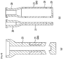
- the present invention relates to a refractory material for use, primarily, in continuous casting equipment, particularly, molten steel vessels such as a converter and a ladle, a tundish, a casting nozzle and the like; and a casting nozzle, such as a long nozzle, an immersion nozzle, a sliding nozzle plate (hereinafter referred to as "SN plate”), an upper nozzle, or a lower nozzle, using the refractory material.
- a refractory material for use, primarily, in continuous casting equipment, particularly, molten steel vessels such as a converter and a ladle, a tundish, a casting nozzle and the like; and a casting nozzle, such as a long nozzle, an immersion nozzle, a sliding nozzle plate (hereinafter referred to as "SN plate”), an upper nozzle, or a lower nozzle, using the refractory material.
- SN plate sliding nozzle plate
- refractory materials in the field of continuous casting e.g., refractory materials for use in a ladle long nozzle used for the purpose of an oxygen-free process between a ladle and a tundish, an immersion nozzle used for the purpose of control of molten steel fluidity between a tundish and a casting mold, an SN plate used for the purpose of control of molten steel flow rate, an Al 2 O 3 -SiO 2 -C based refractory material and an Al 2 O 3 -C based refractory material excellent in thermal shock resistance have been widely employed.
- a component supplied from molten steel For example, as regards high-Mn steel, Ca-treated steel, high-oxygen steel as typified by porcelain enamel steel, or the like, under continuous collision of molten steel against a refractory material, inclusions existing in the molten steel (in this specification, such inclusions existing in molten steel and consisting of non-metal components will hereinafter be also referred to as "slag"), such as (FeO), (MnO), (CaO) and (V 2 O 5 ) (in this specification, a chemical component enclosed in parentheses means that it is a component contained in slag) react with the refractory material to produce a highly erosive composite oxide at a contact interface therebetween, and the resulting composite oxide reacts with the refractory material, while penetrating inside a refractory microstructure ,
- the low-melting-point substance significantly accelerates damage to the refractory material, thereby becoming a factor for deterioration in durability.
- the Al 2 O 3 component added as a primary aggregate to the conventional refractory material is formed as a low-melting-point substance through reaction with oxides such as (FeO), (MnO), (CaO) and (V 2 O 5 ). Therefore, the above techniques fail to obtain a sufficient effect, in fact.
- Patent Document 1 proposes an alumina-magnesia-graphite based refractory material produced using a composition obtained by adding magnesia having a particle size of 0.02 to 1.0 mm or less to a mixture primarily comprised of alumina and graphite, in an amount of 3 to 60 weight% or less, or a refractory material comprising the alumina-magnesia-graphite based refractory material and spinel contained therein.
- the Patent Document 2 proposes a continuous casting nozzle having an inner bore portion a part or an entirety of which is constructed of a refractory material comprises spinel and periclase as a mineral phase, wherein an amount of impurities other than Al 2 O 3 and MgO making up spinel and periclase is 3 weight% or less.
- the Patent Document 3 proposes an immersion nozzle having a nozzle body constructed of a spinal-periclase-graphite based refractory material comprising spinel: 50 to 95 weight%, periclase: 3 to 20 weight%, and graphite: 5 to 30 weight%, with the remainder being unavoidable impurities: 3 weight% or less.
- an MgO component such as magnesia (periclase) or spinel has heretofore been selected in many cases, because it is less likely to form a low-melting-point substance through reaction with the slug components such as (FeO), (MnO), (CaO) and (V 2 O 5 ), as compared to the Al 2 O 3 component.
- magnesia has a thermal expansion rate greater than that of alumina.
- magnesia when magnesia is applied to a casting nozzle, it causes an increase in the risk of crack formation, and imposes restrictions on applicable portions and the amount of addition of magnesia.
- the MgO (periclase) content is about 20 weight% at a maximum, and, if the content exceeds this value, there arises a problem of deterioration in thermal shock resistance, as described in its specification (paragraph [0017]).
- a magnesia aggregate-containing refractory material and a low-carbon refractory material exhibit excellent erosion/corrosion resistance.
- these refractory materials when applied to a member requiring thermal shock resistance such as a casting nozzle, they cause an increase in the risk of crack formation due to their high expansion property, and thus impose restrictions on the amount of addition of MgO.
- the above conventional refractory materials have a problem that, although the MgO component originally owns excellent erosion/corrosion resistance against the slag components, the excellence is not sufficiently utilized because it has to be partially sacrificed for achieving a balance between thermal shock resistance and erosion/corrosion resistance.
- Patent Document 4 discloses a method of producing an MgO-C based unburned brick for use in an SN plate and the like, wherein the method comprises: adding magnesia clinker containing MgO in an amount of 95% or more, in an amount of up to 86 weight%; adding stabilized zirconia (YSZ, CSZ) having a stabilization degree of 80 to 100%, in the form of coarse particles and fine particles; adding unstabilized zirconia (0.044 mm or less) in an amount of 3 to 15 weight% in the form of extra-fine particles; adding 3 to 15 weight% of carbon, metal Al, metal Si and a phenol resin; and subjecting the resulting mixture to kneading, shaping, and hardening heat treatment.
- YSZ, CSZ stabilized zirconia having a stabilization degree of 80 to 100%, in the form of coarse particles and fine particles
- unstabilized zirconia 0.044 mm or less
- the Patent Document 4 relates to an invention intended to enhance thermal shock resistance of a refractory material by utilizing a volume change during crystal transformation of the unstabilized zirconia. In other words, this method induces microscopic defects in a refractory microstructure. Thus, there is a limit on improvement of thermal shock resistance
- Patent Document 5 discloses a refractory material produced using refractory coarse aggregate particles having an average particle size of 10 to 50 mm, wherein respective surfaces of the refractory coarse aggregate particles are coated with a polymer compound such as phenolic resin, whereby a void space can be formed between a surface of each refractory coarse aggregate particle and a matrix to thereby lower the elastic modulus of the refractory material.
- Patent Document 6 discloses an MgO-C based unburned brick having a refractory microstructure comprising 10 to 50 volume% of a magnesia particle having a layer formed therearound to have a thickness of 5 to 100 ⁇ m and comprised of a void space and pitch.
- the layer comprised of a void space and pitch can allegedly block propagation of crack to provide enhanced thermal shock resistance.
- Patent Document 7 discloses a continuous casting nozzle member prepared by subjecting a composition comprising: 80 to 99.5 mass% of a raw material obtained by coating 100 mass parts of a magnesia raw material having a particle size of less than 0.5 mm, with 6 to 30 mass parts of high-softening-point pitch; and 0.5 to 20 mass% of metal powder, to burning in a non-oxidizing atmosphere at a temperature of 500 to 1200°C, wherein the nozzle member has a thermal expansion rate at 1500°C of 1.5% or less.
- Each of the Patent Documents 5 and 6 relates to a technique of preliminarily coating respective surfaces of aggregate particles with a polymer compound, pitch or the like.
- this technique has a problem that a coating agent such as a polymer compound or pitch strongly tends to be unevenly distributed because refractory raw materials have a particle size distribution, particularly, due to a strong cohesive force of extra-fine particles, and thereby it is difficult to uniformly form uniform coatings on respective surface of the particles.
- a coating agent such as a polymer compound or pitch strongly tends to be unevenly distributed because refractory raw materials have a particle size distribution, particularly, due to a strong cohesive force of extra-fine particles, and thereby it is difficult to uniformly form uniform coatings on respective surface of the particles.
- due to difficulty in control of coating thickness it is necessary to add the coating agent in an excessive amount.
- this technique has a problem that, due to damage or peeling of a polymer compound or pitch coating caused by temperature, solvent, inter-particle friction force and others, during a kneading step, it is difficult to sufficiently obtain an expected quality improvement effect, and thereby equality does not become stable.
- the Patent Document 7 discloses a technical concept indicating that it is effective to provide a clearance for absorbing thermal expansion, around each magnesia particle.
- the Patent Document 7 is intended to solve the problem by providing a coating layer comprising a high-softening-point pitch, around each particle, and, during the course of receiving a thermal load, forming a carbide layer (spring-like layer) having a cushioning property or elastic property, from the high-softening-point pitch, as a suitable material having a gas cavity (air layer) around each particle.
- Patent Document 8 describes MgO-C unburned refractory having a structure containing 10-50 vol.% magnesia particles having a layer of 5-100 ⁇ m thickness consisting of gap and pitch in the circumference.
- the present invention primarily addresses a technical problem of significant improvement in thermal shock resistance of an MgO-containing refractory material having excellent erosion/corrosion resistance against slag or in-steel inclusions, i.e., a technical problem of providing a refractory material having both excellent erosion/corrosion resistance and thermal shock resistance, which has hardly been obtainable by the conventional techniques, and a casting nozzle using the refractory material.
- a basic material such as MgO-containing magnesia (periclase) has a strong ion binding property and thereby a thermal expansion amount thereof is large as compared to other refractory particles.
- the thermal expansion amount of the refractory material generally increases in a manner proportional to a presence rate of high-expansion refractory particles.
- a total thermal expansion amount of the refractory material is approximately determined by a sum of products each resulting from multiplying a thermal expansion rate of a respective one of the raw materials by a rate of contribution to the total thermal expansion amount, such as a volume fraction, of the raw material, so-called "additivity rule".
- the conventionally commonly-used means to improve thermal shock resistance of a high-expansion refractory material is a technique of adding a raw material capable of developing an expansion lowering effect and an elastic-modulus lowering effect, e.g., addition of carbon or unstabilized zirconia, or a technique of physically coating respective peripheries of magnesia aggregate particles with pitch or a polymer compound or the like.
- a refractory material of the present invention is prepared by forming an ideal gas cavity space (approximately continuous void layer) around each particle containing MgO (hereinafter referred to as "MgO-containing particle") in a carbon and MgO-containing refractory raw material, and controlling a thickness of the void layer, so that it becomes possible to provide a refractory material capable of controlling thermal expansion thereof without relying on the additivity rule, i.e., a chemical composition thereof to exhibit an outstanding low-expansion property. That is, the essence of the present invention is to form an approximately continuous void layer free of solids such as carbon, around each of the MgO-containing particles exhibiting a high expansion property.
- approximately continuous void layer means that, in cross-section microscopic observation of the periphery of the MgO-containing particle, a contour of a void around the MgO-containing particle has an approximately geometrically similarly magnified shape with respect to a cross-sectional contour of the particle, wherein the particle resides inside the void space, like a ball of a spherical bell (see FIG. 10(a) ).
- the refractory material has a microstructure in which the void layer around each of the MgO-containing particles is free of structural objects, such as carbon, which pose an impediment to thermal expansion of the MgO-containing particle (first requirement), and, secondly, the microstructure is free from a situation where adjacent ones of the MgO-containing particles, or each of the MgO-containing particles and a matrix, are partially in direct contact with each other in a random manner due to unevenness or partial absence of the void layer (second requirement).
- structural objects such as carbon
- the coating material such as combustible liquid is partially peeled or removed from the peripheries of the particles during a kneading step, and it is impossible to control the occurrence and level of this phenomenon.
- the void layer inevitably has a partially thinned region or a partially absent region (see FIG. 11(b) ).
- the void layer exists around the entire periphery of each of the MgO-containing particles, i.e., in a "continuous state" around each of the MgO-containing particles.
- a continuous state around each of the MgO-containing particles.
- the void layer actually exists around the entire periphery of each of the MgO-containing particles, and even when a partial contact state between a certain one of the MgO-containing particles and an adjacent one of the MgO-containing particles or a matrix is observed during verification by microscopic observation, such a state is not a "joined or bonded" state enough to ensure fixing of the certain MgO-containing particle with respect to the adjacent MgO-containing particle or the matrix.
- whether or not there is this "joined or bonded" state is a difference between the present invention and each of the conventional techniques, in terms of the void layer around each of the MgO-containing particles.
- an approximately continuous void layer free of solids such as carbon is formed around each of the MgO-containing particles.
- This provides an advantageous effect that thermal expansion of each of the MgO-containing particles during the course of receiving a thermal load is absorbed by the approximately continuous void layer around the MgO-containing particle, and therefore the thermal expansion of the MgO-containing particle superficially disappears. That is, as long as the void layer exists around each of the MgO-containing particles during the course of receiving a thermal load, a thermal expansion amount of the refractory material consists mainly of a thermal expansion amount of a three-dimensionally continuous carbonaceous matrix region. Thus, it becomes possible to extremely significantly reduce the thermal expansion amount of the refractory material.
- the conventional techniques impose limits on MgO content and use application in order to suppress deterioration in thermal shock resistance, so that an excellent erosion/corrosion-resistant property owned by the refractory material has not been sufficiently utilized so far.
- the present invention does not follow the additivity rule, and therefore can lower the expansion of the refractory material even if it contains a large amount of MgO. This makes it possible to provide a refractory material having thermal shock resistance and erosion/corrosion resistance without sacrificing the excellent erosion/corrosion-resistant property of MgO against slag or in-steel inclusions.
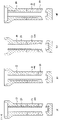
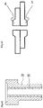
- the present invention can be applied to an MgO-C based refractory material for use in various portions requiring thermal shock resistance, e.g., lining or a region of a main body to be subjected to a contact with molten steel, of a continuous casting nozzle, such as an immersion nozzle, a long nozzle, an upper or lower nozzle or an SN plate, or a casting member, and a molten steel vessel such as a converter.
- a continuous casting nozzle such as an immersion nozzle, a long nozzle, an upper or lower nozzle or an SN plate, or a casting member
- a molten steel vessel such as a converter.
- the present invention provides a refractory material as defined in claims 1 to 5. Furthermore, the present invention provides a casting nozzle which is partially or entirely formed of such a refractory material, as defined in claims 6 to 8.
- the chemical composition of the refractory material of the present invention comprises, in a state after the refractory material is subjected to a heat treatment in a non-oxidizing atmosphere at 1000°C: MgO in an amount of 40 mass% or more; a free carbon component in an amount of 4 to 30 mass%; and one or more selected from the group consisting of B 2 O 3 , P 2 O 5 , SiO 2 and TiO 2 , in a total amount of 0.3 to 3 mass%, with the optional remainder being at least one other type of additional refractory component as defined in the claims.
- the reason that the chemical composition is specified as a result as measured "after the refractory material is subjected to a heat treatment in a non-oxidizing atmosphere at 1000°C" is to promote removal of water from the refractory material and removal of volatile matter from organic substances, hydrates and carbonate compounds in the refractory material, and promote carbonization of an organic binder component, thereby obtaining a stationary state in terms of composition.
- the temperature may be set to 800°C or more if it is just needed to satisfy this requirement, it is set to 1000°C to stabilize a chemical composition in the refractory material to thereby facilitate enhancing analytical accuracy, i.e., to settle spreading of volatile matter in the refractory composition, particularly, in a resin component, and prevent formation of any new substance by a chemical reaction at a temperature of greater than 1000°C.
- a heating time is set to a period to be continued until a change in weight due to heating disappears.
- Specific examples of the heat treatment in a non-oxidizing atmosphere at 1000°C include: a technique of burning the refractory material in a sheath filled with a carbonaceous raw material such as coke; and a technique of holding the refractory material at 1000°C for 1 to 3 hours, in an inert gas atmosphere such as nitrogen or argon, wherein an oxygen concentration is adjusted to 0.1% or less.
- Specific conditions, such as an atmosphere, a holding time and a size of a sample may be arbitrarily selected and determined according to the above purpose.
- the content of the free carbon component is set to 4 to 30 mass%.
- the term “free carbon component” means particle-form (including a meaning of "fiber-form") carbonaceous component produced by subjecting various organic binders, pitch, tar and/or carbon black, except carbides such as B 4 C and SiC, to a heat treatment in a non-oxidizing atmosphere at 1000°C, and crystalline carbon, e.g., graphite.
- the "free carbon component” will hereinafter be also referred to simply as "carbon”.
- a carbonaceous matrix region containing the free carbon component and residing between particles will hereinafter be referred to as "carbonaceous matrix”.
- the carbon content is less than 4 mass%, a three-dimensionally continuous carbonaceous matrix cannot grow in a refractory microstructure, thereby failing to exert a sufficient expansion lowering effect. If the carbon content is greater than 30 mass%, this is advantageous in terms of strength and thermal shock resistance, but, on the other hand, damage to the carbonaceous matrix by molten steel, slag, gas and others becomes severe, and wear of the refractory material increases, causing a problem of deterioration in durability.
- a microstructure of the refractory material (refractory microstructure) of the present invention is constructed such that a void layer having a certain thickness is formed in an interface between a three-dimensionally continuous carbonaceous matrix and each of a plurality of MgO-containing particles residing in the carbonaceous matrix, in such a manner as to surround the MgO-containing particle.
- the refractory material of the present invention has a refractory microstructure in which a void layer exists in an interface between a carbonaceous matrix (carbon-containing matrix microstructure) residing on opposite sides of a maximum-size one of a plurality of MgO-containing particles in the refractory material (hereinafter referred to as "maximum-diameter particle”), and the maximum-diameter particle, wherein a sum of respective thicknesses of the void layer at two positions on the opposite sides is 0.2 to 3.0% in terms of a ratio with respect to a particle size of the maximum-diameter particle.
- maximum-diameter particle a maximum-size one of a plurality of MgO-containing particles in the refractory material
- This refractory microstructure can be specified by microscopic observation thereof at room temperature after being subjected to the heat treatment in a non-oxidizing atmosphere at 1000°C.
- the reason that the microscopic observation of the refractory microstructure is performed "after the refractory material is subjected to the heat treatment in a non-oxidizing atmosphere at 1000°C" is to promote removal of water from the refractory material and removal of volatile matter from organic substances, hydrates and carbonate compounds in the refractory material, and promote carbonization of an organic binder component, thereby obtaining a stationary state in terms of composition.
- the refractory material has already undergone a heat treatment at 1000°C or more, or a heat treatment at 800°C or more depending on a type of the volatile matter, in a manufacturing process thereof, it is possible to perform the microstructure observation and evaluation of a chemical composition except for metal components, using the refractory material in a state of a product just after the manufacturing process.
- a given-thick void layer is formed around each of the MgO-containing particles as highly expansive particles, for the purpose of preliminarily forming, around each of the MgO-containing particles, an expansion-absorbing zone for allowing the MgO-containing particle in the refractory microstructure to freely expand when the refractory material undergoes temperature changes during preheating, casting or cooling, thereby absorbing thermal expansion of the MgO-containing particles at temperatures of up to a given value by the void layers around the particles inside the refractory material to prevent the thermal expansion of the particles from emerging as an thermal expansion amount of the refractory material.
- Patent Documents 5 to 7 When a substance such as carbon exists inside the void layers around the respective particles, as in the aforementioned conventional techniques (Patent Documents 5 to 7), the expansion absorbing ability of the void layers deteriorates, thereby impairing the expansion lowering effect. Differently, in the present invention, an approximately continuous void layer free of foreign substances such as carbon is formed. This makes it possible to drastically reduce the thermal expansion amount of the refractory material.
- respective surfaces of MgO-containing particles are subjected to a contact with water-containing gas or water vapor for a given time, during a heat treatment in a raw material stage or after shaping, to thereby form a hydroxide layer or a carbonate layer on the surfaces of the MgO-containing particles.
- a thickness of a coating layer consisting of a hydroxide layer or a carbonate layer can be adjusted by changing a concentration of water vapor, carbon dioxide gas or the like, a treatment temperature, a treatment time, a pressure of carbon dioxide gas, or an amount of addition of hydroxide.
- a formation temperature of the coating layer is appropriately set to 350°C or less for a carbonate layer, or to 260°C or less for a hydroxide layer.
- a porous active layer containing fine MgO particles (this layer will hereinafter be also referred to simply as "MgO active layer") is formed as a surface layer thereof.
- MgO active layer contains a large amount of fine MgO particles and therefore has a highly reactive property.
- a thickness of the MgO active layer which is originally porous is reduced, and, in microscopic observation at room temperature after the refractory material is subjected to the heat treatment in a non-oxidizing atmosphere at 1000°C, a formation of a void layer around each of the MgO-containing particles can be observed.
- one or more selected from the group consisting of B 2 O 3 , P 2 O 5 , SiO 2 and TiO 2 each of which is an acidic oxide are contained in the refractory microstructure in a total amount of 0.3 to 3 mass%.
- the MgO active layer and the one or more acidic oxides induce an erosive reaction (densification reaction) therebetween, and the reacted region is contracted, so that an approximately continuous void layer is formed around each of the MgO-containing particles.
- an inorganic compound (including a solid solution) of one or more selected from the group consisting of B 2 O 3 , P 2 O 5 , SiO 2 and TiO 2 with MgO is also formed in an entirety or a part of a surface of each of the MgO-containing particles. This inorganic compound can be ascertained by EPMA observation or powder X-ray diffractometry.
- B 2 O 3 and P 2 O 5 are particularly preferable because they have a high vapor pressure during high-temperature heating under coexistence with carbon and can be easily spread in the refractory microstructure in the form of gas.
- the acidic oxides may be used independently, or in the form of a combination of two or more of them, or in the form of a glass powder or a compound containing one or more of them.
- TiO 2 or SiO 2 having difficulty in inducing the densification by itself may be used in combination with B 2 O 3 , P 2 O 5 or the like so as to rapidly promote the densification.
- the acidic oxides may be added in the form of an oxide (metal oxide) from the beginning, or may be added in the form of a hydrate, a hydroxide, a carbonate or an organic compound of a metal oxide, or may be added in the form of a glass powder, a composite oxide powder or an inorganic compound powder.
- a glass powder containing a component other than the acidic oxides serving as effective components, or the like a total amount of the remainder except for the effective components should be limited to 1 mass% or less with respect to the entire refractory material.
- the one or more acidic oxides are present in the refractory material in the form of fine particles having, particularly, a particle size of 0.1 mm or less. In this case, the one or more acidic oxides effectively act in an MgO-active-layer densifying effect.
- the total content of the one or more acidic oxides i.e., effective components, is set to fall within the range of 0.3 to 3 mass%. If the content is less than 0.3 mass%, the MgO-active-layer densifying effect becomes insufficient. On the other hand, if the content is greater than 3 mass%, a reaction product is excessively formed, so that a void layer around each of the MgO-containing particles disappears, resulting in failing to obtain the expansion lowering effect.
- a larger thickness of the void layer around each of the MgO-containing particles is more preferable from a viewpoint of achieving lower thermal expansion.
- the void layer is preferably formed around each of all refractory particles having a thermal expansion amount greater than that of carbon.
- the void layers around the refractory particles cause deterioration in strength of the refractory material.
- the void layer around each of the MgO-containing particles is obtained by: inducing a chemical reaction between MgO and gas or liquid on respective surfaces of refractory particles in a pretreatment stage of an MgO-containing raw material or in a manufacturing process of the refractory material, i.e., forming a coating layer consisting of a hydroxide layer or a carbonate layer on each surface of MgO-containing particles; and then thermally decomposing the coating layer at a temperature equal to or greater than a decomposition temperature of the coating layer, while utilizing a densification reaction with one or more of B 2 O 3 , P 2 O 5 , SiO 2 and TiO 2 , in a high-temperature range.
- refractory particles have a particle size distribution through a sieving operation.
- the hydroxide layer or the carbonate layer can be approximately evenly formed over the entire region of a surface of each of the refractory particles even though they have different particle sizes.
- micro-space value (hereinafter also referred to simply as "MS value"
- MS value a ratio of a thickness of the void layer to a particle size
- a particle size per-particle void layer thickness rate (rate of a thickness of void layer per particle)
- a smaller particle has a larger MS value. Therefore, knowing an MS value of a coarse particle is equivalent to knowing a lower limit of the per-particle void layer thickness rate in the refractory microstructure, so that the microstructure can be roughly evaluated based on MS values in the refractory microstructure.
- the MS value represents a minimum value of a rate of the expansion-absorbing zone existing around each particle in the refractory microstructure.
- the inventers calculated the MS value in the following manner. Through microscopic microstructure observation of the refractory material, ten coarse particles are selected in descending order of particle size, and an arbitrary line passing through a center of a circle inscribed in each of the coarse particles is drawn. Further, three lines passing through the center of the circle are drawn at a 45-degree pitch with reference to the arbitrary line. That is, total four lines are drawn per coarse particle. Then, a length (D1, D2, D3, D4) between contour points of the coarse particle on each of the lines at two positions on opposite sides of the coarse particle, and a sum (L1, L2, L3, L4) of thicknesses of a void layer on each of the lines at two positions on the opposite sides and outside a particle interface are measured. In the measurement of each thickness of the void layer, a minimum thickness is measured based on a line perpendicular to a surface of the particle.
- MS1, MS2, MS3 and MS4 are calculated by the above formula using the values obtained using the four lines, and an average of them is calculated as an MS value of one of the coarse particles.
- Respective MS values of the preliminarily selected ten particles are calculated in the above manner, and averaged to obtain an MS value of the refractory microstructure.
- an MS value is obtained by averaging respective MS values of ten coarse particles selected in descending order of particle size. This is one way to obtain an MS value of a maximum-diameter particle in a microscopic observation field. That is, considering measurement error, an average of respective MS values of ten coarse particles selected in descending order of particle size is obtained and deemed as an MS value of a maximum-diameter particle in a microscopic observation field (the MS value of the maximum-diameter particle will hereinafter be referred to simply as "MS value", unless otherwise noted).
- a thickness of a void layer around each particle which is capable of exerting the expansion lowering effect while achieving a balance between respective ones of strength, corrosion/abrasion resistance and abrasion resistance, is, in terms of a thickness of the void layer around a maximum-diameter particle, in the range of 0.1 to 1.5% of a particle size of the maximum-diameter particle.
- the void layer exists at two positions on opposite sides of each particle.
- thermal expansion amount in a microstructure where all particles consist MgO-containing particles, supposing that a thermal expansion rate of the MgO-containing particle is 2.4% at 1500°C because a thermal expansion rate of the MgO-containing particle (aggregate particle) is generally 2.0% or more at 1500°C, while estimating that a thermal expansion of a carbonaceous matrix surrounding the particle is 0.4% at the same temperature, a difference therebetween is 2.0%.
- a casting temperature in steel making is about 1500°C.
- each of the MgO-containing particles can have an approximately continuous void layer thickness rate (expansion-absorbing zone), depending on casting conditions, so that it becomes possible to achieve lower thermal expansion without relying on the additivity rule.
- a void layer may be formed around each of the MgO-containing particles to thereby achieve lower thermal expansion in the entire refractory material.
- the content of the MgO-containing particles is less than 40 mass%, continuity of the additional refractory material particles each having no effective void layer increases, so that it becomes impossible to expect a lower thermal expansion rate in the entire refractory material. Meanwhile, as a prerequisite for effectively bringing out a low expansion property while developing effective strength, it is necessary that the carbonaceous matrix is three-dimensionally continuous.
- the refractory raw material particles to be used it is necessary to limit the number of the particles, so as to lower continuity thereof, and it is also necessary to employ a particle size composition in which a rate of a fine particle fraction causing an increase in the continuity is minimized.
- a particle size of the refractory raw material particles in the present invention on the assumption that an amount of the refractory material except for the free carbon component is 100 mass%, a total amount having a particle size of 0.1 mm or less among the raw material particles is 45 mass% or less. This makes it easy to develop the expansion lowering effect.
- the content of particles of the refractory components having a particle size of 0.1 mm or less is less than 5 mass%, thermal shock resistance is excellent, but the refractory microstructure is liable to become excessively coarse so that a loss is likely to be accelerated due to in-steel components, molten steel stream, oxidation phenomenon and others.
- refractory raw material particles comprised of a solid solution or a compound comprising a commonly-used refractory component except for B 2 O 3 , P 2 O 5 , SiO 2 and TiO 2 .
- the inventive refractory material contains an optional remainder of at least one other type of additional refractory component selected from the group consisting of an Al 2 O 3 component; an oxide component selected from ZrO 2 , Y 2 O 3 , CaO and Cr 2 O 3 ; and SiC, preferably, one or more selected from the group consisting of Al 2 O 3 , ZrO 2 , Y 2 O 3 , CaO, Cr 2 O 3 and SiC.
- the refractory particles corresponding to the content have difficulty in applying an appropriate internal pressure to a surrounding carbonaceous partition wall (matrix) corresponding to the PET bottle, so that enhancement in reinforcing the carbonaceous partition is weakened, and, in extreme cases, the carbonaceous partition wall is damaged due to its deformation, thereby causing deterioration in material strength.
- a surrounding carbonaceous partition wall matrix
- the carbonaceous partition wall is damaged due to its deformation, thereby causing deterioration in material strength.
- 2.0% is enough just in calculation.
- a range of the MS value capable of achieving a balance between strength and thermal expansion rate is extended up to a value (3.0%) slightly greater than 2.0%.
- the MS value is greater than 3.0%, the aforementioned undesirable situation will occur all over the refractory microstructure at a temperature equivalent to the casting temperature. This causes deterioration in macroscopic material strength, and degradation in physical properties such as corrosion resistance and abrasion resistance. If the MS value is less than 0.2%, the expansion lowering effect cannot be obtained although mechanical strength is good.
- the refractory material of the present invention on the assumption that an amount of the refractory material except for the free carbon component is 100 mass%, a total amount of particles having a particle size of 0.1 mm or less among of the raw material particles is 5 to 45 mass%, and a maximum thermal expansion rate at temperatures of up to 1500°C is 1.1% or less.
- the refractory material desirably acts, particularly, as a type requiring thermal shock resistance in an effective manner.
- the present invention is based on a finding that further excellent lower expansion property can be obtained by lowering continuity of the raw material particles, in addition to providing the refractory microstructure in which the void layer is provided around each of the MgO-containing particles.
- the content of raw material particles having a particle size of 0.1 mm or less is set to 5 to 45 mass%. If the content of the refractory particles having a particle size of 0.1 mm or less is less than 5 mass%, the microstructure of the refractory material becomes excessively coarse, thereby causing an increase in loss under molten steel stream. On the other hand, if the content is greater than 45 mass%, thermal expansion rate increases, thereby causing deterioration in thermal shock resistance.
- the maximum thermal expansion rate at temperatures of up to 1500°C is set to 1.1% or less.
- the refractory material effectively acts, particularly, as a type requiring thermal shock resistance and abrasion resistance in molten steel. This makes it possible to reduce the thermal expansion rate of the refractory material containing the MgO-containing particles to thereby overcome a weak point in thermal shock resistance due to a high expansion property of the MgO-containing particles.
- the refractory material of the present invention is usable in various applications including casting nozzles.
- MgO component As is well known, a role of the MgO component is to impart erosion/corrosion resistance, based on its property that it hardly forms a low-melting-point substance even in a contact reaction with components in a molten substance containing a large amount of CaO and consisting almost of slag (such as a molten substance derived from a so-called slag layer floating on molten steel, or the like), or in a contact reaction with fine basic inclusions such as (FeO), (MnO) and (CaO) dispersed in molten steel, because MgO is basis oxide.
- slag such as a molten substance derived from a so-called slag layer floating on molten steel, or the like
- fine basic inclusions such as (FeO), (MnO) and (CaO) dispersed in molten steel, because MgO is basis oxide.
- an effect of lowering thermal expansion in the entire refractory material can be obtained by the technique of forming the void layer around each of the MgO-containing particles, so that it becomes possible to increase the MgO content in the refractory material without causing deterioration in thermal shock resistance, and therefore provide a refractory material having both of high thermal shock resistance and erosion/corrosion resistance, which has hardly been achievable by the conventional techniques.
- the refractory material of the present invention also contains the free carbon component in an amount of 4 to 30 mass%.
- MgO-C reaction MgO (solid) + C (solid) ⁇ Mg (gas) + CO (gas)
- Examples of the casting environment which is liable to induce the above reaction include: an environment which has a high casting temperature and is likable to cause CO gas generated in a refractory microstructure to easily move (from the refractory microstructure) to the outside, for example, in a continues casting operation, an inner wall region of a pouring nozzle such as a stopper nozzle or an immersion nozzle. Particularly, in such a region, a contact with slag components such as in-steel inclusions is more likely to occur, so that the slag components can intrude into the refractory microstructure to induce a melting-point lowering reaction with MgO, and accelerate the MgO - C reaction.
- bonds linking the MgO-containing particles to each other and the MgO-containing particles as aggregate are gasified and vanished to form brittle areas, so that deterioration in erosion/corrosion resistance and mechanical strength, and a metal and slag infiltration phenomenon, become more likely to occur. Further, such gas components are spread over and deposited in the void layers existing around the respective MgO-containing particles in the refractory microstructure, in the form of fine particles or whiskers. This is likely to cause disappearance of the void layers and thus exert a negative influence on the expansion lowering effect.
- the inventors have found, as a technique of maintaining soundness of the refractory microstructure and the expansion lowering effect even in environments which are liable to accelerate the MgO - C reaction, a technique of adding a certain amount of Al 2 O 3 component to a composition, wherein the composition is set to a specific range allowing the refractory material to maintain excellent erosion/corrosion resistance without impairing soundness of the refractory microstructure and the expansion lowering effect, over a long period of time of casting operation.
- a part of the MgO component is replaced with an Al 2 O 3 component, wherein the composition is adjusted such that a mass ratio (Al 2 O 3 / MgO) is set in the range of 0 to 0.65.
- the lower limit of the mass ratio (Al 2 O 3 / MgO) is set to 0, because there is a possibility that no Al 2 O 3 component is added.
- the addition of the Al 2 O 3 component is based on the finding that the Al 2 O 3 component allows a part of the MgO component to be transformed into a spinel phase which is thermodynamically stable, so that it becomes possible to suppress the MgO - C reaction.
- the suppression of the MgO - C reaction formation of whiskers by re-oxidation of a volatile component in a gas cavity space, particularly, in the void layers around the respective MgO-containing particles, can be suppressed, so that it becomes possible to maintain the void layers around the respective MgO-containing particles, and thus maintain the expansion lowering effect of the refractory material until a final stage of a casting operation.
- the addition of the Al 2 O 3 component can suppress the MgO - C reaction to exert excellent effects.
- non-significant or no void layer is formed between each of Al 2 O 3 particles and the carbonaceous matrix, although the present invention is intended to form an approximately continuous void layer between a surface of each of the MgO-containing particles and the carbonaceous matrix. Therefore, an increase in amount of Al 2 O 3 leads to a relatively large increase in thermal expansion rate, as compared to the MgO-containing particles each having a sufficient void. Thus, it is preferable to impose a limit on an amount of addition of Al 2 O 3 .
- a refractory material for a region necessary to have a thermal shock-resistant property as well as high erosion/corrosion-resistant property requires a low thermal expansion property.
- the mass ratio (Al 2 O 3 / MgO) is set to greater than 0.65, thermal expansion tends to significant increase as compared to other refractory materials, so that a balance in thermal expansion is disrupted, and a risk of the occurrence of crack formation increases.
- the composition should be adjusted to fall within the above range.
- ZrO 2 , Y 2 O 3 , CaO, Cr 2 O 3 and/or SiC As a refractory component other than the Al 2 O 3 component, it is possible to add ZrO 2 , Y 2 O 3 , CaO, Cr 2 O 3 and/or SiC. These may be used independently, and it is also possible to use various types of ZrO 2- based raw materials (unstabilized zirconia, partially stabilized zirconia, fully stabilized zirconia, and alumina-zirconia), chromia, magnesia-chromia, and spinel. In this case, the expansion lowering effect can be developed by setting the content of the MgO component to at least 40 mass% or more. SiC is preferably added in an amount of 15 mass% or less.
- a contact with outside air containing oxidizing gas is unavoidable.
- a function of preventing oxidation of the refractory material is important to bringing out its desired effects until a final stage of a casting operation.
- a refractory product for steel making, and a flow-rate controlling SN plate, an upper nozzle or a lower nozzle, particularly, requiring strength, oxidation resistance and erosion/corrosion resistance is generally not subjected to coating of an anti-oxidant, differently from an immersion nozzle and a long nozzle, so that it is essential to add an antioxidant to a raw material thereof.
- the refractory material of the present invention may contain one or more metals selected from the group consisting of Al, Si and Mg, in a total amount of 0.5 to 6 mass%, whereby primarily the anti-oxidation function during a casting operation can be brought out. If the content is less than 0.5 mass%, the anti-oxidation function becomes insufficient.
- the content is greater than 6 mass%, a product derived from the additive is deposited in an air hole/gas cavity space, and the void layers around the respective MgO-containing particles, undesirably causing difficulty in maintaining the expansion lowering effect, and deterioration in thermal shock resistance of the refractory material.
- Al, Si and Mg may be contained independently in the form of a metal element, or may be contained in the form of an alloy powder formed of two or more of them.
- Si may be preferably used in combination with Al, because it has an effect of suppressing formation of aluminum carbide after a heat treatment or during use.
- B 4 C is effectively contained.
- the content of B 4 C is appropriately set to 0.5 to 1.5 mass%. If the content is less than 0.5 mass%, the anti-oxidation function becomes insufficient. On the other hand, if the content is greater than 1.5 mass%, it becomes difficult to maintain the expansion lowering effect, and erosion/corrosion resistance becomes more likely to deteriorate.
- the one or more metals or alloy selected from the group consisting of Al, Si and Mg, and B 4 C can be mixedly used in the above respective amounts.
- the present invention can significantly improve thermal shock resistance of an carbon and MgO-containing refractory material to provide a refractory material having both excellent erosion/corrosion resistance and thermal shock resistance, which has hardly been obtainable by the conventional techniques, and a casting nozzle using the refractory material.
- a role of MgO-containing particles used in the present invention is to bring out an expansion lowering effect based on formation of an approximately continuous void layer around a surface of each of the particles, and improve erosion/corrosion resistance based on an MgO component.
- the MgO-containing particles typically include a particle-form magnesia-based raw material consisting primarily of naturally-produced or artificially-synthesized MgO.
- magnesia-based raw material it is possible to use either one of fused magnesia and sintered magnesia. In either case, the purity of MgO is preferably 90 mass% or more.
- the raw material for the MgO-containing particles it is also possible to partially use a spinel-based raw material containing a theoretical spinel composition (MgO ⁇ Al 2 O 3 ).
- MgO ⁇ Al 2 O 3 a theoretical spinel composition
- the MgO-containing particles i.e., an MgO source, are at least partially made of a magnesia-based raw material (periclase).
- the refractory material of the present invention contains one or more metal oxides (hereinafter referred to as "specific metal oxides") selected from the group consisting of B 2 O 3 , P 2 O 5 , SiO 2 and TiO 2 .
- specific metal oxides selected from the group consisting of B 2 O 3 , P 2 O 5 , SiO 2 and TiO 2 .
- As a raw material therefor it is possible to use one or more selected from oxides, hydroxides, colloidal substances, esters, metal alkoxides, etc., of B, P, Si and Ti, independently or in the form of a combination of two or more thereof.
- B 2 O 3 source it is possible to use boron oxide, tetraboric acid, metaboric acid, orthoboric acid, or borate ester.
- borosilicate glass it is also possible to use borosilicate glass.
- phosphoric acid As a P 2 O 5 source, it is possible to use phosphoric acid, phosphoric ester, various phosphoric salts, such as aluminum phosphate and sodium phosphate, or phosphate hydrate.
- SiO 2 source it is possible to use orthosilicate, metasilicate, anhydrous silica powder, colloidal silica, a solution type of ethyl silicate or the like, silicate, or aluminosilicate, without causing deterioration in quality.
- TiO 2 source it is possible to use titanium oxide, titania hydrate, titanium compound, or colloidal dispersion.
- the one or more specific metal oxides selected from the group consisting of B 2 O 3 , P 2 O 5 , SiO 2 and TiO 2 it is desirable to adequately perform dispersion during kneading, and use as the raw materials, a fine powder having a particle size of 0.1 mm or less, or a liquid type.
- the MgO component, B 2 O 3 , P 2 O 5 , SiO 2 and TiO 2 it is possible to contain at least one other type of additional refractory component.
- the additional refractory component an Al 2 O 3 component is most preferable, for the aforementioned reason.
- the additional refractory component other than Al 2 O 3 it is possible to use an oxide component such as ZrO 2 , Y 2 O 3 , CaO or Cr 2 O 3 , and SiC. These may be added independently, or may be used in the form of a solid solution or a compound.
- the expansion lowering effect can be developed by setting the content of the MgO component to at least 40 mass% or more.
- SiC is preferably added in an amount of 15 mass% or less.
- a natural raw material can be used as refractory particles, as mentioned above.
- impurities an inevitable component other than effective components
- a content of the inevitable component is limited to about 3 mass % or less, preferably, about 2 mass % or less, more preferably, about 1 mass % or less.
- the content of the inevitable component can be adjusted to some extent, for example, by employing a technique of selecting each raw material whose effective components are high in purity, or a technique of enhancing cleaning or the like during a manufacturing process.
- a carbon raw material serving as a binder may be used.
- binder carbon it is preferable to use a phenolic resin, pitch or tar, because they can leave residual carbon as a binding network, at a high rate after burning in a non-oxidizing atmosphere.
- a solid carbonaceous raw material except for the binder carbon raw material may be arbitrarily used.
- the solid carbonaceous raw material except for the binder carbon raw material it is possible to use a particle-form carbonaceous raw material such as graphite or carbon black, or a fiber-form carbonaceous raw material such as carbon fibers.
- a ratio of a free carbon component to the refractory material is in the range of 4 to 30 mass %, while taking into account a rate of a loss of the binder carbon raw material (a rate after subtraction of a rate of residual carbon) and a rate of a loss of the solid carbonaceous raw material (a loss of impurities on heating, etc.), and others.
- the oxide component B 2 O 3 , P 2 O 5 , SiO 2 and/or TiO 2 around each of the MgO-containing particles it is preferable to perform the kneading after preparing the oxide components B 2 O 3 , P 2 O 5 , SiO 2 and TiO 2 , in a liquid form or a fine powder form, and directly adding, to the MgO-containing particles, additives using the liquid or fine power-form oxide components independently or in the form of a combination of two or more of them.
- FIG. 1(a) illustrates one type of immersion nozzle (casting nozzle) in which a refractory material 20 of the present invention is disposed to defined a part of a region of the nozzle to be subjected to a contact with molten steel, in the form of a single layer having a surface to be subjected to a contact with molten steel, and a back surface.
- the refractory material 20 of the present invention may be additionally disposed to form a powder line portion 21.
- the resulting immersion nozzle is configured such that the refractory product 20 of the present invention is disposed to define an entirety of the region to be subjected to a contact with molten steel, in the form of a single layer having a surface to be subjected to a contact with molten steel, and a back surface.
- FIG. 1(a) illustrates an example of a circular cylindrical-shaped type
- a casting nozzle using the refractory material of the present invention is not limited to a particular shape, such a circular cylindrical shape.
- the refractory material of the present invention can be used in immersion nozzles (casting nozzles) having various shapes, such as a flat shape, an elliptic shape or a funnel shape (a funnel shape having a diametrally enlarged upper portion), primarily used for thin slab casting, as illustrated in FIG. 1(b) .
- FIG. 2(a) illustrates another type of immersion nozzle (casting nozzle) which comprising a plurality of layers comprised of: a first layer disposed to define a part (in this type, inner bore surface) of a region of the nozzle to be subjected to a contact with molten steel, wherein the first layer is composed of the refractory material 20 of the present invention; and a second layer (a powder line portion 21 or a nozzle body 22) disposed on a back side of the first layer, wherein the second layer has a composition different from that of the refractory material 20.
- the plurality of layers are integrated together in direct contact relation to each other.
- FIG. 2(b) illustrates yet another type in which, in addition to the part in FIG.
- the refractory material 20 of the present invention is further used to define an inner peripheral surface and an outer peripheral surface of a discharge port, as the region to be subjected to a contact with molten steel, wherein a lower portion of the nozzle including a portion located immediately upstream of the discharge port is entirely formed of the refractory material 20 of the present invention.
- a surface layer defining an inner peripheral surface to be subjected to a contact with molten steel may be formed of the refractory material 20 of the present invention, and the remaining region may be formed of a different refractory material, such as an alumina-graphite based refractory material.
- refractory material of the powder line portion 21 and the nozzle body 22 on the back side of the first layer, illustrated in FIG. 2
- a refractory material comprising carbon and refractory particles comprised of one or more selected from the group consisting of Al 2 O 3 , SiO 2 , MgO and ZrO 2 and compounds thereof; and a refractory material having a composition which falls within the range of that of the refractory material of the present invention but is different from that of the refractory material disposed to define a part or an entirety of the region to be subjected to a contact with molten steel.
- the above multi-layer casting nozzle may be produced by: partitioning a raw material mixture filling space in a target region inside a CIP molding mold, at a position radially distant from a molten steel contact surface (inner bore surface) by a given thickness; filling one sub-space on the side of the molten steel contact surface with a raw material mixture for the refractory material of the present invention, while filling the other sub-space on a back side thereof with a raw material mixtures, for example, for the refractory material comprising carbon and refractory particles composed of one or more selected from the group consisting of Al 2 O 3 , SiO 2 , MgO and ZrO 2 and compounds thereof; removing a jig used for the partition, such as a partition plate; and then subjecting the mixtures to pressure forming.
- FIG. 3 illustrates one type of long nozzle in which the refractory material 20 of the present invention is disposed to define a part of a region to be subjected to a contact with molten steel.
- FIG. 4 and FIG. 5 illustrate, respectively, another type of long nozzle and one type of lower nozzle each of which comprising a plurality of layers comprised of: a first layer disposed to define a part of a region of the nozzle to be subjected to a contact with molten steel, wherein the first layer is composed of the refractory material 20 of the present invention; and a second layer (a nozzle body 22) disposed on a back side of the first layer, wherein the second layer has a composition different from that of the refractory material 20.
- the plurality of layers are integrated together in direct contact relation to each other.
- FIG. 6 illustrates one type of SN plate formed of the refractory material 20 of the present invention.
- a CaO-based alumina adhesion-resisting refractory material 23 may be used to define a region to be subjected to a contact with molten steel, such as an inner bore surface of a casting nozzle, and the refractory material 20 of the present invention may be used for a portion on a back side thereof, and a part or an entirety of an intermediate layer of the nozzle.
- the CaO-based refractory material and the MgO-based refractory material of the present invention are a basic material in common.
- a phenolic resin was added as a binder to each of a plurality of types of refractory raw materials (refractory particles) having respective compositions illustrated in Tables 1 to 9, and, after kneading, the resulting mixture was adjusted to have formability suitable for shaping.
- the mixture was formed into a desired shape by a CIP process, and the shaped body was subjected to a hardening-drying treatment at temperatures of up to 300°C and then to a heat treatment in a non-oxidizing atmosphere at 1000°C.
- fused magnesia clinker particles and spinel fine powder were used as the Mg-containing particles.
- the obtained refractory material was subjected to analysis for chemical composition, microstructure observation, and an evaluation test.
- microstructure observation a refractory microstructure was observed through a microscope after being subjected to impregnation with a resin and then mirror-finishing by mechanical polishing, and then an MS value was calculated in the aforementioned manner.
- the refractory material was evaluated in terms of thermal expansion rate, wear resistance (erosion/corrosion resistance), thermal shock resistance, and oxidation resistance.
- thermal expansion rate a thermal expansion rate at temperatures of up to 1500°C was measured (according to JIS R 2207-3) to evaluate a maximum thermal expansion rate at temperatures of up to 1500°C.
- the evaluation of wear resistance (erosion/corrosion resistance) of the refractory material was performed by an in-molten steel rotation test using high-oxygen steel.
- the in-molten steel rotation test is a method for evaluating erosion/corrosion resistance against molten steel to be owned as one prerequisite by the refractory material of the present invention.
- the term "wear” or "wear damage” is used as a concept generally expressing a state in which a sample after the test is dimensionally reduced, irrespective of whether a damaging mechanism is a loss caused by a chemical reaction (corrosion due to lowering in meting point, etc.) or a loss caused by a mechanical abrasive action, such as abrasion (so-called "erosion").
- FIG. 7 schematically illustrates an in-molten steel rotation test method
- FIG. 8 illustrates a test piece for the in-molten steel rotation test
- FIG. 8(a) is a schematic front view
- FIG. 8(b) is a schematic top plan view.
- a test piece 10 held at a lower portion of a holder 11 is immersed in molten steel 13 in a crucible 12.
- the test piece 10 is formed in a rectangular parallelepiped shape and the number of test pieces 10 is four.
- the holder 11 is formed in a square pillar shape, wherein the four test pieces 10 are fixed, respectively, to four side surfaces of the lower portion of the holder 11.
- the test pieces 10 are inserted, respectively, into four recesses provided in the square pillar-shaped holder 11, in such a manner that they can be pulled out therefrom after completion of the test.
- An upper portion of the holder 11 is connected to and held by a non-illustrated rotary shaft in a rotatable manner about a longitudinal axis thereof as a rotation axis.
- the holder 11 is made of a zirconia-carbon based refractory material and formed to have a square shape with a side of 40 mm, in horizontal cross-section, and a longitudinal length of 160 mm.
- Each of the test pieces 10 has a portion exposed from the holder 11.
- the exposed portion has a heightwise length of 20 mm, a widthwise length of 20 mm and a protruding length of 25 mm.
- the test piece 10 is attached to the holder at a position located upwardly away from a lower end thereof by 10 mm.
- the crucible 12 is made of a refractory material and formed in a cylindrical shape having an inner diameter of 130 mm and a depth of 190 mm.
- the holder 11 is immersed at a depth of 50 mm or more.
- the crucible 12 is placed inside a high-frequency induction furnace 14. Although not illustrated, an upper surface of the crucible can be closed by a cover.
- the test pieces 10 are immersed in the molten steel 13 (high-oxygen steel, in-steel oxygen concentration: 100 to 150 ppm), and rotated at an average circumferential velocity of 1 m/sec at an outermost periphery of each of the test pieces 10.
- the temperature of the molten steel 13 is kept in the range of 1550 to 1600°C.
- the test pieces 10 are pulled up, and, an adhesion/wear speed ( ⁇ m/min) is measured.
- each of the test pieces 10 after completion of the test is detached from the holder, and cut along a horizontal plane with respect to the rotation axis. Then, respective lengths at 6 positions of the cut surface are measured at 3 mm pitch in a direction from an edge 10a of the test piece 10 toward the rotation axis, and averaged. Respective lengths at the same positions of the test piece 10 before the test are also measured and averaged, as illustrated in FIG. 9(a) .
- the wear speed is essentially required to be 35 ⁇ m/min or less.
- the wear resistance (erosion/corrosion resistance) of the material was relatively evaluated by using the following criteria for the wear speed: Excellent ( ⁇ ): ⁇ 0 to 5 ⁇ m/min, Good ( ⁇ ): ⁇ 5 to 20 ⁇ m/min, Acceptable ( ⁇ ): 21 to 35 ⁇ m/min, and NG ( ⁇ ): > 36 ⁇ m/mm.
- the endurance limit temperature ⁇ T of thermal shock resistance to be owned as one prerequisite by the refractory material of the present invention, particularly, a continuous casting refractory material requiring thermal shock resistance is 800°C or more.
- the endurance limit temperature ⁇ T was 800°C or more
- the sample was evaluated as Good (o)
- the endurance limit temperature ⁇ T was 700°C or less
- the sample was evaluated as NG ( ⁇ )
- the sample was evaluated as Acceptable ( ⁇ ).
- Oxidation resistance was evaluated by placing a sample (30 mm square) of the refractory material in an atmospheric atmosphere at 800°C or 1400°C. Immediately after holding the temperature for 3 hours, the sample was taken out and, after being cooled, cut in a horizontal direction. Then, an average thickness of a decarburized layer was measured.
- the sample When the thickness of the decarburized layer was less than 0.5 mm at the above two temperatures, the sample was evaluated as Excellent ( ⁇ ), and when it was less than 1 mm at the above two temperatures, the sample was evaluated as Good (o). On the other hand, when the thickness of the decarburized layer was greater than 1 mm at the above two temperatures, the sample was evaluated as NG ( ⁇ ).
- Inventive Examples 1 to 7 and Comparative Examples 1 to 10 presented in Tables 1 and 2 are examples in which, regarding a group of refractory materials containing MgO as a primary component, i.e., using MgO-containing particles containing periclase as a primary component, an influence of the void layer thickness rate between the maximum-diameter MgO-containing particle and the carbonaceous matrix (MS value) was researched.
- Each of Comparative Examples 1 to 9 corresponds to at least one of: a refractory material in which the MgO-containing particles are not subjected to the surface treatment; a refractory material in which the content of B 2 O 3 is not in the range of 0.3 to 3 mass% (no B 2 O 3 is contained); and a refractory material in which the free carbon component is not in the range of 4 to 30 mass%.
- Table 3 is an example in which an influence of the content of MgO and each component containing alumina, zirconia, alumina-zirconia and silicon carbide, as the additional refractory component, was researched.
- the wear speed was calculated from a maximum dimensional change in a width direction before and after the immersion.
- the wear speed was less than 25 ⁇ m/min, the sample was evaluated as Excellent ( ⁇ ), and, when it was 25 to 50 ⁇ m/min, the sample was evaluated as Good (o).
- the wear speed was greater than 50 ⁇ m/min (but there was a remaining portion), the sample was evaluated as Acceptable ( ⁇ ), and, when there was no remaining portion, the sample was evaluated as NG ( ⁇ ).
- ( ⁇ ), ( ⁇ ) and ( ⁇ ) were determined as usable (OK).
- Table 4 presents a result of research on an influence of the content of B 2 O 3 in regard to a group of refractory materials in which the content of the free carbon component is 17 mass% (falling within the range of 4 to 30 mass%) and the MgO-containing particles is subjected to the surface treatment, in a group of refractory materials containing MgO as a primary component (a group of refractory materials using MgO-containing particles containing periclase as a primary component).
- Table 5 presents a result of research on a range of the MS value in regard to a group of refractory materials containing MgO as a primary component (a group of refractory materials using MgO-containing particles containing periclase as a primary component).
- samples were prepared by setting the content of B 2 O 3 to 3 mass% (the maximum amount in the allocable range defined in the appended claims), and changing a level of the surface treatment for the MgO-containing particles.
- Table 6 presents a result of research on, in a group of refractory materials containing MgO as a primary component (a group of refractory materials using MgO-containing particles containing periclase as a primary component), a refractory material using borosilicate glass as the B 2 O 3 source, a refractory material using P 2 O 5 , SiO 2 or TiO 2 as a component (specific metal oxide) other than B 2 O 3 , and a refractory material using a combination of two or more specific metal oxides including B 2 O 3 .
- Table 7 presents a result of research on an influence of the Al 2 O 3 component.
- Inventive Examples 27, 28, 30 and 31 are examples in which a part of the MgO-containing particles is replaced with an alumina fine power as corundum. Observing these Inventive Examples on the basis of Inventive Example 3 where a mass ratio of (Al 2 O 3 / MgO) is 0, it is proven that the maximum thermal expansion rate at temperatures of up to 1500°C becomes larger as the mass ratio is gradually increase to 0.13 (Inventive Example 27), 0.50 (Inventive Example 28) and 0.65 (Inventive Example 30).
- the thermal shock resistance deteriorates to a level approximately equal to ( ⁇ ) although it falls with a usable range.
- the reason is as follows. Firstly, even if the thickness of the void layer around each of the MgO-containing particles is approximately the same, an absolute amount of the void layers (around the respective MgO-containing particles) becomes smaller along with an increase in amount of the alumina particles, because no void layer exists around each of the alumina particles.
- a rigid skeletal structure formed with poor stress absorbing ability by the alumina particles becomes larger along with an increase in amount of the alumina particles.
- the alumina particles mixedly exist together with the MgO-containing particles in a fine particle fraction, and therefore a spinel formation reaction progresses with time.
- the mass ratio of (Al 2 O 3 / MgO) is preferably set to 0.65 or less.
- Table 8 presents a result of research on an influence of a ratio of MgO-containing particles having a particle size of 0.1 mm or less to the entire MgO-containing particles.
- ratio of MgO-containing particles having a particle size of - 0.1 mm means a ratio of a part of MgO-containing particles having a particle size of 0.1 mm or less, in a state at room temperature after the refractory material is subjected to the heat treatment in a non-oxidizing atmosphere at 1000°C, and on an assumption that an amount of the refractory material except for the free carbon component and boron oxide is 100 mass%. This applies to other Tables.
- Table 9 presents a result of research on an influence of addition of one or more metals or alloys selected from the group consisting of Al, Si and Mg, or addition of B 4 C, independently or in combination with one or more of the metals or alloys.
- fine graphite particle size: under 0.1 mm
- the chemical composition of Al, Si, Mg or B 4 C in Table 9 is presented by mass%, on an assumption that an entire amount of the refractory material as measured after being subjected to a heat treatment in a non-oxidizing atmosphere at 600°C before start of the heat treatment in a non-oxidizing atmosphere at 1000°C is 100 mass%, and any other chemical component is presented by mass% as measured after the refractory material is subjected to a heat treatment in a non-oxidizing atmosphere at 1000°C.
- Inventive Examples 38, 39 and 43 correspond to a group of refractory materials comprising an Al-Si alloy containing metal Al and metal Si at a mass ratio of 3 : 1, and Inventive Examples 40 to 42 correspond to a group of refractory materials additionally using B 4 C in combination with the Al-Si alloy.
- Inventive Examples 44 to 46 correspond to a group of refractory materials containing only metal Al independently, and Inventive Example 47 corresponds to a refractory material using B 4 C in combination with the metal Al.
- Inventive Examples 48 to 50 correspond to a group of refractory materials containing only metal Si independently, and Inventive Example 51 corresponds to a refractory material using B 4 C in combination with the metal Si.
- Inventive Example 52 corresponds to a refractory material containing only B 4 C independently
- Inventive Example 53 corresponds to a refractory material comprising an Al-Mg alloy containing metal Al and metal Mg at a mass ratio of 1 : 1
- Al-Si alloy and Al-Mg alloy are used.
- a mixture of Al and Si or a mixture of Al and Mg may also be used to obtain the same effect.
Landscapes
- Engineering & Computer Science (AREA)
- Chemical & Material Sciences (AREA)
- Ceramic Engineering (AREA)
- Manufacturing & Machinery (AREA)
- Materials Engineering (AREA)
- Structural Engineering (AREA)
- Organic Chemistry (AREA)
- Mechanical Engineering (AREA)
- Composite Materials (AREA)
- Compositions Of Oxide Ceramics (AREA)
- Ceramic Products (AREA)
- Casting Support Devices, Ladles, And Melt Control Thereby (AREA)
Applications Claiming Priority (2)
| Application Number | Priority Date | Filing Date | Title |
|---|---|---|---|
| JP2013058733 | 2013-03-21 | ||
| PCT/JP2014/057472 WO2014148530A1 (ja) | 2013-03-21 | 2014-03-19 | 耐火物及び鋳造用ノズル |
Publications (3)
| Publication Number | Publication Date |
|---|---|
| EP2977126A1 EP2977126A1 (en) | 2016-01-27 |
| EP2977126A4 EP2977126A4 (en) | 2017-03-22 |
| EP2977126B1 true EP2977126B1 (en) | 2022-05-04 |
Family
ID=51580205
Family Applications (1)
| Application Number | Title | Priority Date | Filing Date |
|---|---|---|---|
| EP14767723.1A Active EP2977126B1 (en) | 2013-03-21 | 2014-03-19 | Refractory material and nozzle for casting |
Country Status (12)
| Country | Link |
|---|---|
| US (1) | US9821371B2 (ko) |
| EP (1) | EP2977126B1 (ko) |
| JP (1) | JP6027676B2 (ko) |
| KR (1) | KR101722041B1 (ko) |
| CN (1) | CN105188987B (ko) |
| AU (1) | AU2014239412B2 (ko) |
| BR (1) | BR112015024070B1 (ko) |
| CA (1) | CA2903361C (ko) |
| ES (1) | ES2916203T3 (ko) |
| RU (1) | RU2637196C2 (ko) |
| TW (1) | TWI502058B (ko) |
| WO (1) | WO2014148530A1 (ko) |
Families Citing this family (14)
| Publication number | Priority date | Publication date | Assignee | Title |
|---|---|---|---|---|
| EP2789960B1 (de) * | 2013-04-12 | 2018-12-19 | Refractory Intellectual Property GmbH & Co. KG | Verfahren zur Bestimmung des Zustandes einer feuerfesten Auskleidung eines metallurgischen Schmelzgefässes |
| US10935320B2 (en) | 2013-04-12 | 2021-03-02 | Refractory Intellectual Property Gmbh & Co. Kg | Method for determining the state of a refractory lining of a metallurgical vessel for molten metal in particular |
| JP6663230B2 (ja) * | 2016-01-25 | 2020-03-11 | 黒崎播磨株式会社 | ノズル構造体 |
| KR101907930B1 (ko) * | 2016-10-17 | 2018-10-15 | 주식회사 포스코 | 노즐 및 이의 제조 방법 |
| WO2018155118A1 (ja) | 2017-02-24 | 2018-08-30 | Jfeスチール株式会社 | 黒鉛含有耐火物および黒鉛含有耐火物の製造方法 |
| WO2019078563A1 (ko) * | 2017-10-17 | 2019-04-25 | 엘지전자 주식회사 | 리튬이차전지 양극활물질 소성용 내화갑 및 그 제조 방법 |
| JP6726651B2 (ja) * | 2017-11-24 | 2020-07-22 | 明智セラミックス株式会社 | 連続鋳造用ノズルの製造方法 |
| CN110304909A (zh) * | 2019-07-21 | 2019-10-08 | 山东耐火材料集团有限公司 | 精密铸造用中频炉干式料及其制备方法 |
| CN110918970B (zh) * | 2019-11-15 | 2021-06-25 | 中天钢铁集团有限公司 | 一种降低硅脱氧钢加工过程断丝率的浸入式水口内衬材料 |
| CN111099884A (zh) * | 2019-12-23 | 2020-05-05 | 江苏奥能耐火材料有限公司 | 一种浸入式水口添加金属锆的陶瓷结合抗冲刷材料 |
| RU2729806C1 (ru) * | 2020-01-09 | 2020-08-12 | Акционерное общество «ЕВРАЗ Нижнетагильский металлургический комбинат» (АО «ЕВРАЗ НТМК») | Сталеразливочный погружной стакан |
| CN111470853B (zh) * | 2020-03-26 | 2022-06-17 | 北京利尔高温材料股份有限公司 | 一种镁质喷补料及其应用 |
| JP7071605B1 (ja) * | 2022-03-02 | 2022-05-19 | 黒崎播磨株式会社 | 連続鋳造用の耐火物及び耐火物部材 |
| JP7071604B1 (ja) * | 2022-03-02 | 2022-05-19 | 黒崎播磨株式会社 | 連続鋳造用の耐火物及び耐火物部材 |
Citations (1)
| Publication number | Priority date | Publication date | Assignee | Title |
|---|---|---|---|---|
| JPH06321625A (ja) * | 1993-05-10 | 1994-11-22 | Harima Ceramic Co Ltd | MgO−C質不焼成れんが |
Family Cites Families (25)
| Publication number | Priority date | Publication date | Assignee | Title |
|---|---|---|---|---|
| US3664853A (en) * | 1970-03-06 | 1972-05-23 | Bethlehem Steel Corp | Impregnated fired refractory shape and method of producing same |
| JP2599428B2 (ja) | 1988-06-02 | 1997-04-09 | 川崎炉材株式会社 | MgO−C系不焼成れんがの製造方法 |
| JP2667734B2 (ja) * | 1990-07-20 | 1997-10-27 | ローム株式会社 | サーマルプリントヘッドの製造方法 |
| JPH059062A (ja) * | 1991-06-28 | 1993-01-19 | Nippon Steel Corp | 塩基性耐火物 |
| JP3197680B2 (ja) * | 1993-05-07 | 2001-08-13 | 新日本製鐵株式会社 | MgO−C質不焼成れんがの製造方法 |
| IN191421B (ko) * | 1994-06-15 | 2003-11-29 | Vesuvius Frnance Sa | |
| JPH09278546A (ja) * | 1996-04-05 | 1997-10-28 | Nippon Steel Corp | 溶融金属用容器内張り不定形流し込み耐火物及びその成形体 |
| JP3213699B2 (ja) | 1997-05-08 | 2001-10-02 | 品川白煉瓦株式会社 | 鋼の連続鋳造用ノズル |
| JPH1138818A (ja) | 1997-07-16 | 1999-02-12 | Minolta Co Ltd | 画像転写装置 |
| JP3358989B2 (ja) | 1998-05-14 | 2002-12-24 | 品川白煉瓦株式会社 | 鋼の連続鋳造用浸漬ノズル |
| US6461991B1 (en) | 1998-01-28 | 2002-10-08 | Krosaki Corporation | Alumina-magnesia-graphite refractory |
| JP4737846B2 (ja) | 2000-02-15 | 2011-08-03 | 株式会社リコー | 非磁性一成分現像方式 |
| BE1013540A3 (fr) * | 2000-05-29 | 2002-03-05 | Rotary Nozzle Internat S A | Plaque refractaire. |
| JP4542281B2 (ja) | 2001-04-16 | 2010-09-08 | 新日本製鐵株式会社 | コーティングを施した耐火物用粗骨材、それを用いた耐火物及び金属精錬用溶融金属容器 |
| JP2004323260A (ja) | 2003-04-22 | 2004-11-18 | Shinagawa Refract Co Ltd | 連続鋳造用ノズル材及び連続鋳造用ノズル |
| JP4835040B2 (ja) | 2005-05-20 | 2011-12-14 | 株式会社豊田自動織機 | 産業車両の制御装置、産業車両、及び産業車両の制御方法 |
| JP2006321626A (ja) | 2005-05-20 | 2006-11-30 | Duplo Corp | 給紙装置 |
| DE202007018373U1 (de) * | 2007-03-07 | 2008-08-21 | Refratechnik Holding Gmbh | Feuerfester kohlenstoffgebundener Magnesiastein |
| CN101888910B (zh) * | 2007-12-05 | 2012-12-19 | 新日本制铁株式会社 | 浸渍喷嘴及连续铸造方法 |
| JP2009278546A (ja) | 2008-05-16 | 2009-11-26 | Mitsubishi Electric Corp | 送信ダイバーシチ方法、移動局、基地局および無線通信システム |
| KR101310737B1 (ko) * | 2008-07-28 | 2013-09-25 | 신닛테츠스미킨 카부시키카이샤 | 연속 주조용 노즐 |
| TWI421225B (zh) * | 2010-05-19 | 2014-01-01 | Krosaki Harima Corp | A refractory, a continuous casting nozzle using the refractory and a method for manufacturing the continuous casting nozzle, and a continuous casting method using the continuous casting nozzle |
| JP2013081113A (ja) | 2011-10-05 | 2013-05-02 | Canon Inc | 電子機器 |
| PL2786975T3 (pl) | 2011-12-01 | 2019-06-28 | Krosakiharima Corporation | Produkt ogniotrwały i dysza odlewnicza |
| WO2014112493A1 (ja) * | 2013-01-16 | 2014-07-24 | 黒崎播磨株式会社 | マグネシアカーボンれんが |
-
2014
- 2014-03-19 AU AU2014239412A patent/AU2014239412B2/en active Active
- 2014-03-19 BR BR112015024070A patent/BR112015024070B1/pt active IP Right Grant
- 2014-03-19 JP JP2015506817A patent/JP6027676B2/ja active Active
- 2014-03-19 RU RU2015144969A patent/RU2637196C2/ru active
- 2014-03-19 WO PCT/JP2014/057472 patent/WO2014148530A1/ja active Application Filing
- 2014-03-19 KR KR1020157019945A patent/KR101722041B1/ko active IP Right Grant
- 2014-03-19 US US14/777,909 patent/US9821371B2/en active Active
- 2014-03-19 ES ES14767723T patent/ES2916203T3/es active Active
- 2014-03-19 EP EP14767723.1A patent/EP2977126B1/en active Active
- 2014-03-19 CA CA2903361A patent/CA2903361C/en active Active
- 2014-03-19 CN CN201480016398.6A patent/CN105188987B/zh active Active
- 2014-03-21 TW TW103110677A patent/TWI502058B/zh active
Patent Citations (1)
| Publication number | Priority date | Publication date | Assignee | Title |
|---|---|---|---|---|
| JPH06321625A (ja) * | 1993-05-10 | 1994-11-22 | Harima Ceramic Co Ltd | MgO−C質不焼成れんが |
Also Published As
| Publication number | Publication date |
|---|---|
| CN105188987B (zh) | 2016-11-16 |
| ES2916203T3 (es) | 2022-06-29 |
| JP6027676B2 (ja) | 2016-11-16 |
| WO2014148530A1 (ja) | 2014-09-25 |
| BR112015024070A2 (pt) | 2017-07-18 |
| AU2014239412A1 (en) | 2015-10-29 |
| EP2977126A4 (en) | 2017-03-22 |
| RU2015144969A (ru) | 2017-04-28 |
| TW201510194A (zh) | 2015-03-16 |
| US20160297003A1 (en) | 2016-10-13 |
| CA2903361A1 (en) | 2014-09-25 |
| TWI502058B (zh) | 2015-10-01 |
| KR101722041B1 (ko) | 2017-04-03 |
| KR20150100849A (ko) | 2015-09-02 |
| BR112015024070B1 (pt) | 2019-12-24 |
| AU2014239412B2 (en) | 2016-05-26 |
| CA2903361C (en) | 2018-01-02 |
| CN105188987A (zh) | 2015-12-23 |
| EP2977126A1 (en) | 2016-01-27 |
| RU2637196C2 (ru) | 2017-11-30 |
| JPWO2014148530A1 (ja) | 2017-02-16 |
| US9821371B2 (en) | 2017-11-21 |
Similar Documents
| Publication | Publication Date | Title |
|---|---|---|
| EP2977126B1 (en) | Refractory material and nozzle for casting | |
| TWI466844B (zh) | Refractory and casting nozzles | |
| JPWO2018155030A1 (ja) | 鋼の鋳造用耐火物,及びスライディングノズル装置用のプレート | |
| JP2015193511A (ja) | 鋳造用耐火物、並びにそれを使用した鋳造用ノズル及びスライディングノズル用プレート | |
| JP6193793B2 (ja) | 鋳造用耐火物、並びにそれを使用した鋳造用ノズル及びスライディングノズル用プレート | |
| WO2022215727A1 (ja) | キャスタブル耐火物 | |
| JP7416117B2 (ja) | キャスタブル耐火物および溶鋼鍋 | |
| WO2011058811A1 (ja) | スライディングノズルプレート | |
| JP6154772B2 (ja) | アルミナ−炭化珪素−炭素質れんが | |
| JP2010082653A (ja) | スライディングノズル装置用の塩基性プレート耐火物 | |
| JP5920412B2 (ja) | 連続鋳造ノズル | |
| JP2012192430A (ja) | アルミナ−カーボン質スライドゲートプレート | |
| JPH0352423B2 (ko) | ||
| TW202124329A (zh) | CaO-ZrO組成物、CaO-ZrO組成物之製造方法、含CaO-ZrO之耐火物及鑄造用噴嘴 | |
| JP3176836B2 (ja) | 不定形耐火物 | |
| JP2017001889A (ja) | 不焼成プレート耐火物 | |
| JP2016185890A (ja) | 耐火物及びスライディングノズル用プレート | |
| Rout | Studies on the Effect of Alumina Aggregates on he Performances of Alumna-Carbon Refractories | |
| JPH09278539A (ja) | 不定形耐火物 |
Legal Events
| Date | Code | Title | Description |
|---|---|---|---|
| PUAI | Public reference made under article 153(3) epc to a published international application that has entered the european phase |
Free format text: ORIGINAL CODE: 0009012 |
|
| 17P | Request for examination filed |
Effective date: 20151021 |
|
| AK | Designated contracting states |
Kind code of ref document: A1 Designated state(s): AL AT BE BG CH CY CZ DE DK EE ES FI FR GB GR HR HU IE IS IT LI LT LU LV MC MK MT NL NO PL PT RO RS SE SI SK SM TR |
|
| AX | Request for extension of the european patent |
Extension state: BA ME |
|
| DAX | Request for extension of the european patent (deleted) | ||
| A4 | Supplementary search report drawn up and despatched |
Effective date: 20170220 |
|
| RIC1 | Information provided on ipc code assigned before grant |
Ipc: B22D 41/54 20060101ALI20170214BHEP Ipc: C04B 35/106 20060101ALI20170214BHEP Ipc: C04B 35/01 20060101ALI20170214BHEP Ipc: C04B 35/043 20060101ALI20170214BHEP Ipc: B22D 11/10 20060101AFI20170214BHEP Ipc: C04B 35/482 20060101ALI20170214BHEP |
|
| STAA | Information on the status of an ep patent application or granted ep patent |
Free format text: STATUS: EXAMINATION IS IN PROGRESS |
|
| 17Q | First examination report despatched |
Effective date: 20190129 |
|
| STAA | Information on the status of an ep patent application or granted ep patent |
Free format text: STATUS: EXAMINATION IS IN PROGRESS |
|
| GRAP | Despatch of communication of intention to grant a patent |
Free format text: ORIGINAL CODE: EPIDOSNIGR1 |
|
| STAA | Information on the status of an ep patent application or granted ep patent |
Free format text: STATUS: GRANT OF PATENT IS INTENDED |
|
| INTG | Intention to grant announced |
Effective date: 20211028 |
|
| GRAS | Grant fee paid |
Free format text: ORIGINAL CODE: EPIDOSNIGR3 |
|
| GRAA | (expected) grant |
Free format text: ORIGINAL CODE: 0009210 |
|
| STAA | Information on the status of an ep patent application or granted ep patent |
Free format text: STATUS: THE PATENT HAS BEEN GRANTED |
|
| AK | Designated contracting states |
Kind code of ref document: B1 Designated state(s): AL AT BE BG CH CY CZ DE DK EE ES FI FR GB GR HR HU IE IS IT LI LT LU LV MC MK MT NL NO PL PT RO RS SE SI SK SM TR |
|
| REG | Reference to a national code |
Ref country code: GB Ref legal event code: FG4D |
|
| REG | Reference to a national code |
Ref country code: CH Ref legal event code: EP |
|
| REG | Reference to a national code |
Ref country code: AT Ref legal event code: REF Ref document number: 1488476 Country of ref document: AT Kind code of ref document: T Effective date: 20220515 |
|
| REG | Reference to a national code |
Ref country code: DE Ref legal event code: R096 Ref document number: 602014083558 Country of ref document: DE |
|
| REG | Reference to a national code |
Ref country code: FI Ref legal event code: FGE |
|
| REG | Reference to a national code |
Ref country code: IE Ref legal event code: FG4D |
|
| REG | Reference to a national code |
Ref country code: NL Ref legal event code: FP |
|
| REG | Reference to a national code |
Ref country code: ES Ref legal event code: FG2A Ref document number: 2916203 Country of ref document: ES Kind code of ref document: T3 Effective date: 20220629 |
|
| REG | Reference to a national code |
Ref country code: LT Ref legal event code: MG9D |
|
| REG | Reference to a national code |
Ref country code: AT Ref legal event code: MK05 Ref document number: 1488476 Country of ref document: AT Kind code of ref document: T Effective date: 20220504 |
|
| PG25 | Lapsed in a contracting state [announced via postgrant information from national office to epo] |
Ref country code: SE Free format text: LAPSE BECAUSE OF FAILURE TO SUBMIT A TRANSLATION OF THE DESCRIPTION OR TO PAY THE FEE WITHIN THE PRESCRIBED TIME-LIMIT Effective date: 20220504 Ref country code: PT Free format text: LAPSE BECAUSE OF FAILURE TO SUBMIT A TRANSLATION OF THE DESCRIPTION OR TO PAY THE FEE WITHIN THE PRESCRIBED TIME-LIMIT Effective date: 20220905 Ref country code: NO Free format text: LAPSE BECAUSE OF FAILURE TO SUBMIT A TRANSLATION OF THE DESCRIPTION OR TO PAY THE FEE WITHIN THE PRESCRIBED TIME-LIMIT Effective date: 20220804 Ref country code: LT Free format text: LAPSE BECAUSE OF FAILURE TO SUBMIT A TRANSLATION OF THE DESCRIPTION OR TO PAY THE FEE WITHIN THE PRESCRIBED TIME-LIMIT Effective date: 20220504 Ref country code: HR Free format text: LAPSE BECAUSE OF FAILURE TO SUBMIT A TRANSLATION OF THE DESCRIPTION OR TO PAY THE FEE WITHIN THE PRESCRIBED TIME-LIMIT Effective date: 20220504 Ref country code: GR Free format text: LAPSE BECAUSE OF FAILURE TO SUBMIT A TRANSLATION OF THE DESCRIPTION OR TO PAY THE FEE WITHIN THE PRESCRIBED TIME-LIMIT Effective date: 20220805 Ref country code: BG Free format text: LAPSE BECAUSE OF FAILURE TO SUBMIT A TRANSLATION OF THE DESCRIPTION OR TO PAY THE FEE WITHIN THE PRESCRIBED TIME-LIMIT Effective date: 20220804 Ref country code: AT Free format text: LAPSE BECAUSE OF FAILURE TO SUBMIT A TRANSLATION OF THE DESCRIPTION OR TO PAY THE FEE WITHIN THE PRESCRIBED TIME-LIMIT Effective date: 20220504 |
|
| PG25 | Lapsed in a contracting state [announced via postgrant information from national office to epo] |
Ref country code: RS Free format text: LAPSE BECAUSE OF FAILURE TO SUBMIT A TRANSLATION OF THE DESCRIPTION OR TO PAY THE FEE WITHIN THE PRESCRIBED TIME-LIMIT Effective date: 20220504 Ref country code: PL Free format text: LAPSE BECAUSE OF FAILURE TO SUBMIT A TRANSLATION OF THE DESCRIPTION OR TO PAY THE FEE WITHIN THE PRESCRIBED TIME-LIMIT Effective date: 20220504 Ref country code: LV Free format text: LAPSE BECAUSE OF FAILURE TO SUBMIT A TRANSLATION OF THE DESCRIPTION OR TO PAY THE FEE WITHIN THE PRESCRIBED TIME-LIMIT Effective date: 20220504 Ref country code: IS Free format text: LAPSE BECAUSE OF FAILURE TO SUBMIT A TRANSLATION OF THE DESCRIPTION OR TO PAY THE FEE WITHIN THE PRESCRIBED TIME-LIMIT Effective date: 20220904 |
|
| PG25 | Lapsed in a contracting state [announced via postgrant information from national office to epo] |
Ref country code: SM Free format text: LAPSE BECAUSE OF FAILURE TO SUBMIT A TRANSLATION OF THE DESCRIPTION OR TO PAY THE FEE WITHIN THE PRESCRIBED TIME-LIMIT Effective date: 20220504 Ref country code: SK Free format text: LAPSE BECAUSE OF FAILURE TO SUBMIT A TRANSLATION OF THE DESCRIPTION OR TO PAY THE FEE WITHIN THE PRESCRIBED TIME-LIMIT Effective date: 20220504 Ref country code: RO Free format text: LAPSE BECAUSE OF FAILURE TO SUBMIT A TRANSLATION OF THE DESCRIPTION OR TO PAY THE FEE WITHIN THE PRESCRIBED TIME-LIMIT Effective date: 20220504 Ref country code: EE Free format text: LAPSE BECAUSE OF FAILURE TO SUBMIT A TRANSLATION OF THE DESCRIPTION OR TO PAY THE FEE WITHIN THE PRESCRIBED TIME-LIMIT Effective date: 20220504 Ref country code: DK Free format text: LAPSE BECAUSE OF FAILURE TO SUBMIT A TRANSLATION OF THE DESCRIPTION OR TO PAY THE FEE WITHIN THE PRESCRIBED TIME-LIMIT Effective date: 20220504 Ref country code: CZ Free format text: LAPSE BECAUSE OF FAILURE TO SUBMIT A TRANSLATION OF THE DESCRIPTION OR TO PAY THE FEE WITHIN THE PRESCRIBED TIME-LIMIT Effective date: 20220504 |
|
| REG | Reference to a national code |
Ref country code: DE Ref legal event code: R097 Ref document number: 602014083558 Country of ref document: DE |
|
| PLBE | No opposition filed within time limit |
Free format text: ORIGINAL CODE: 0009261 |
|
| STAA | Information on the status of an ep patent application or granted ep patent |
Free format text: STATUS: NO OPPOSITION FILED WITHIN TIME LIMIT |
|
| PG25 | Lapsed in a contracting state [announced via postgrant information from national office to epo] |
Ref country code: AL Free format text: LAPSE BECAUSE OF FAILURE TO SUBMIT A TRANSLATION OF THE DESCRIPTION OR TO PAY THE FEE WITHIN THE PRESCRIBED TIME-LIMIT Effective date: 20220504 |
|
| 26N | No opposition filed |
Effective date: 20230207 |
|
| PG25 | Lapsed in a contracting state [announced via postgrant information from national office to epo] |
Ref country code: SI Free format text: LAPSE BECAUSE OF FAILURE TO SUBMIT A TRANSLATION OF THE DESCRIPTION OR TO PAY THE FEE WITHIN THE PRESCRIBED TIME-LIMIT Effective date: 20220504 |
|
| PGFP | Annual fee paid to national office [announced via postgrant information from national office to epo] |
Ref country code: BE Payment date: 20230310 Year of fee payment: 10 |
|
| PGFP | Annual fee paid to national office [announced via postgrant information from national office to epo] |
Ref country code: ES Payment date: 20230406 Year of fee payment: 10 |
|
| PG25 | Lapsed in a contracting state [announced via postgrant information from national office to epo] |
Ref country code: MC Free format text: LAPSE BECAUSE OF FAILURE TO SUBMIT A TRANSLATION OF THE DESCRIPTION OR TO PAY THE FEE WITHIN THE PRESCRIBED TIME-LIMIT Effective date: 20220504 |
|
| REG | Reference to a national code |
Ref country code: CH Ref legal event code: PL |
|
| GBPC | Gb: european patent ceased through non-payment of renewal fee |
Effective date: 20230319 |
|
| PG25 | Lapsed in a contracting state [announced via postgrant information from national office to epo] |
Ref country code: LU Free format text: LAPSE BECAUSE OF NON-PAYMENT OF DUE FEES Effective date: 20230319 |
|
| REG | Reference to a national code |
Ref country code: IE Ref legal event code: MM4A |
|
| PG25 | Lapsed in a contracting state [announced via postgrant information from national office to epo] |
Ref country code: GB Free format text: LAPSE BECAUSE OF NON-PAYMENT OF DUE FEES Effective date: 20230319 |
|
| PG25 | Lapsed in a contracting state [announced via postgrant information from national office to epo] |
Ref country code: LI Free format text: LAPSE BECAUSE OF NON-PAYMENT OF DUE FEES Effective date: 20230331 Ref country code: IT Free format text: LAPSE BECAUSE OF FAILURE TO SUBMIT A TRANSLATION OF THE DESCRIPTION OR TO PAY THE FEE WITHIN THE PRESCRIBED TIME-LIMIT Effective date: 20220504 Ref country code: IE Free format text: LAPSE BECAUSE OF NON-PAYMENT OF DUE FEES Effective date: 20230319 Ref country code: GB Free format text: LAPSE BECAUSE OF NON-PAYMENT OF DUE FEES Effective date: 20230319 Ref country code: FR Free format text: LAPSE BECAUSE OF NON-PAYMENT OF DUE FEES Effective date: 20230331 Ref country code: CH Free format text: LAPSE BECAUSE OF NON-PAYMENT OF DUE FEES Effective date: 20230331 |
|
| PGFP | Annual fee paid to national office [announced via postgrant information from national office to epo] |
Ref country code: NL Payment date: 20240311 Year of fee payment: 11 |
|
| PGFP | Annual fee paid to national office [announced via postgrant information from national office to epo] |
Ref country code: FI Payment date: 20240306 Year of fee payment: 11 Ref country code: DE Payment date: 20240325 Year of fee payment: 11 |