EP2971424B1 - Automated film pickup and placement method for insulating glass units - Google Patents
Automated film pickup and placement method for insulating glass units Download PDFInfo
- Publication number
- EP2971424B1 EP2971424B1 EP14714839.9A EP14714839A EP2971424B1 EP 2971424 B1 EP2971424 B1 EP 2971424B1 EP 14714839 A EP14714839 A EP 14714839A EP 2971424 B1 EP2971424 B1 EP 2971424B1
- Authority
- EP
- European Patent Office
- Prior art keywords
- sheet
- vacuum
- platen
- pickup
- corner
- Prior art date
- Legal status (The legal status is an assumption and is not a legal conclusion. Google has not performed a legal analysis and makes no representation as to the accuracy of the status listed.)
- Not-in-force
Links
- 238000000034 method Methods 0.000 title claims description 46
- 239000011521 glass Substances 0.000 title claims description 22
- 125000006850 spacer group Chemical group 0.000 claims description 18
- 239000000463 material Substances 0.000 claims description 8
- 230000005484 gravity Effects 0.000 claims description 6
- 229920000642 polymer Polymers 0.000 claims description 5
- 230000007246 mechanism Effects 0.000 claims description 2
- 230000037303 wrinkles Effects 0.000 description 6
- 239000000853 adhesive Substances 0.000 description 5
- 230000001070 adhesive effect Effects 0.000 description 5
- 238000009413 insulation Methods 0.000 description 5
- 230000033001 locomotion Effects 0.000 description 5
- 238000004519 manufacturing process Methods 0.000 description 5
- 229920000139 polyethylene terephthalate Polymers 0.000 description 5
- 239000005020 polyethylene terephthalate Substances 0.000 description 5
- 230000008569 process Effects 0.000 description 5
- 239000000758 substrate Substances 0.000 description 5
- 229920002367 Polyisobutene Polymers 0.000 description 3
- 230000000694 effects Effects 0.000 description 3
- -1 polyethylene terephthalate Polymers 0.000 description 3
- 239000000565 sealant Substances 0.000 description 3
- 238000005265 energy consumption Methods 0.000 description 2
- 238000005516 engineering process Methods 0.000 description 2
- 238000010438 heat treatment Methods 0.000 description 2
- 238000012986 modification Methods 0.000 description 2
- 230000004048 modification Effects 0.000 description 2
- 239000002699 waste material Substances 0.000 description 2
- 229920002799 BoPET Polymers 0.000 description 1
- 229920006257 Heat-shrinkable film Polymers 0.000 description 1
- 230000003213 activating effect Effects 0.000 description 1
- 230000004888 barrier function Effects 0.000 description 1
- 230000008901 benefit Effects 0.000 description 1
- 230000005540 biological transmission Effects 0.000 description 1
- 238000007664 blowing Methods 0.000 description 1
- 230000008859 change Effects 0.000 description 1
- 238000000576 coating method Methods 0.000 description 1
- 238000010276 construction Methods 0.000 description 1
- 238000001816 cooling Methods 0.000 description 1
- 238000003708 edge detection Methods 0.000 description 1
- 238000004134 energy conservation Methods 0.000 description 1
- 239000002803 fossil fuel Substances 0.000 description 1
- 238000001802 infusion Methods 0.000 description 1
- 230000003287 optical effect Effects 0.000 description 1
- 229920006254 polymer film Polymers 0.000 description 1
- 230000002250 progressing effect Effects 0.000 description 1
- 230000005855 radiation Effects 0.000 description 1
- 230000003595 spectral effect Effects 0.000 description 1
- 238000007669 thermal treatment Methods 0.000 description 1
- 230000009466 transformation Effects 0.000 description 1
- 230000000007 visual effect Effects 0.000 description 1
Images

Classifications
-
- B—PERFORMING OPERATIONS; TRANSPORTING
- B65—CONVEYING; PACKING; STORING; HANDLING THIN OR FILAMENTARY MATERIAL
- B65H—HANDLING THIN OR FILAMENTARY MATERIAL, e.g. SHEETS, WEBS, CABLES
- B65H5/00—Feeding articles separated from piles; Feeding articles to machines
- B65H5/08—Feeding articles separated from piles; Feeding articles to machines by grippers, e.g. suction grippers
-
- B—PERFORMING OPERATIONS; TRANSPORTING
- B65—CONVEYING; PACKING; STORING; HANDLING THIN OR FILAMENTARY MATERIAL
- B65G—TRANSPORT OR STORAGE DEVICES, e.g. CONVEYORS FOR LOADING OR TIPPING, SHOP CONVEYOR SYSTEMS OR PNEUMATIC TUBE CONVEYORS
- B65G49/00—Conveying systems characterised by their application for specified purposes not otherwise provided for
- B65G49/05—Conveying systems characterised by their application for specified purposes not otherwise provided for for fragile or damageable materials or articles
- B65G49/06—Conveying systems characterised by their application for specified purposes not otherwise provided for for fragile or damageable materials or articles for fragile sheets, e.g. glass
- B65G49/068—Stacking or destacking devices; Means for preventing damage to stacked sheets, e.g. spaces
-
- B—PERFORMING OPERATIONS; TRANSPORTING
- B25—HAND TOOLS; PORTABLE POWER-DRIVEN TOOLS; MANIPULATORS
- B25J—MANIPULATORS; CHAMBERS PROVIDED WITH MANIPULATION DEVICES
- B25J11/00—Manipulators not otherwise provided for
-
- B—PERFORMING OPERATIONS; TRANSPORTING
- B25—HAND TOOLS; PORTABLE POWER-DRIVEN TOOLS; MANIPULATORS
- B25J—MANIPULATORS; CHAMBERS PROVIDED WITH MANIPULATION DEVICES
- B25J15/00—Gripping heads and other end effectors
- B25J15/06—Gripping heads and other end effectors with vacuum or magnetic holding means
- B25J15/0616—Gripping heads and other end effectors with vacuum or magnetic holding means with vacuum
-
- B—PERFORMING OPERATIONS; TRANSPORTING
- B65—CONVEYING; PACKING; STORING; HANDLING THIN OR FILAMENTARY MATERIAL
- B65H—HANDLING THIN OR FILAMENTARY MATERIAL, e.g. SHEETS, WEBS, CABLES
- B65H9/00—Registering, e.g. orientating, articles; Devices therefor
- B65H9/04—Fixed or adjustable stops or gauges
-
- E—FIXED CONSTRUCTIONS
- E06—DOORS, WINDOWS, SHUTTERS, OR ROLLER BLINDS IN GENERAL; LADDERS
- E06B—FIXED OR MOVABLE CLOSURES FOR OPENINGS IN BUILDINGS, VEHICLES, FENCES OR LIKE ENCLOSURES IN GENERAL, e.g. DOORS, WINDOWS, BLINDS, GATES
- E06B3/00—Window sashes, door leaves, or like elements for closing wall or like openings; Layout of fixed or moving closures, e.g. windows in wall or like openings; Features of rigidly-mounted outer frames relating to the mounting of wing frames
- E06B3/66—Units comprising two or more parallel glass or like panes permanently secured together
- E06B3/67—Units comprising two or more parallel glass or like panes permanently secured together characterised by additional arrangements or devices for heat or sound insulation or for controlled passage of light
- E06B3/6715—Units comprising two or more parallel glass or like panes permanently secured together characterised by additional arrangements or devices for heat or sound insulation or for controlled passage of light specially adapted for increased thermal insulation or for controlled passage of light
-
- E—FIXED CONSTRUCTIONS
- E06—DOORS, WINDOWS, SHUTTERS, OR ROLLER BLINDS IN GENERAL; LADDERS
- E06B—FIXED OR MOVABLE CLOSURES FOR OPENINGS IN BUILDINGS, VEHICLES, FENCES OR LIKE ENCLOSURES IN GENERAL, e.g. DOORS, WINDOWS, BLINDS, GATES
- E06B3/00—Window sashes, door leaves, or like elements for closing wall or like openings; Layout of fixed or moving closures, e.g. windows in wall or like openings; Features of rigidly-mounted outer frames relating to the mounting of wing frames
- E06B3/66—Units comprising two or more parallel glass or like panes permanently secured together
- E06B3/673—Assembling the units
- E06B3/67365—Transporting or handling panes, spacer frames or units during assembly
- E06B3/67386—Presses; Clamping means holding the panes during assembly
-
- B—PERFORMING OPERATIONS; TRANSPORTING
- B65—CONVEYING; PACKING; STORING; HANDLING THIN OR FILAMENTARY MATERIAL
- B65G—TRANSPORT OR STORAGE DEVICES, e.g. CONVEYORS FOR LOADING OR TIPPING, SHOP CONVEYOR SYSTEMS OR PNEUMATIC TUBE CONVEYORS
- B65G49/00—Conveying systems characterised by their application for specified purposes not otherwise provided for
- B65G49/05—Conveying systems characterised by their application for specified purposes not otherwise provided for for fragile or damageable materials or articles
- B65G49/06—Conveying systems characterised by their application for specified purposes not otherwise provided for for fragile or damageable materials or articles for fragile sheets, e.g. glass
- B65G49/067—Sheet handling, means, e.g. manipulators, devices for turning or tilting sheet glass
Definitions
- the present invention relates generally to the operation of automated or robotic assembly equipment, especially for the manufacturing of windows, and in particular to any such equipment adapted for pickup of sheets, panels, films, webs or laminates of various sizes at a first location and the placement or attachment of such material at a desired second location, such as to frames of multi-pane insulating glass units (IGUs).
- IGUs multi-pane insulating glass units
- climate control In architectural structures, generally the most energy demanding activity is climate control. Whether cooling or heating, the desire to maintain the interior temperature of a structure at a temperature comfortable for the average human in standard attire can be very energy intensive. While, in some climates, the outside temperature is commonly within a desirable range and climate control is inexpensive and not heavily used, in most environments, at least for a portion of the year, there is a desire to alter the environment within a structure compared to the environment outside. In some environments, the temperature differential between the inside of a structure and the outside environment can be large with differences in temperature of 20oC or more.
- One of the best ways to both control the energy expended to alter the temperature and to maintain a temperature in a structure is to properly insulate the structure. While not an active technology in most cases, insulation allows for the temperature differential inside and outside the structure to be maintained without as much infusion of energy. Good insulation is a barrier to heat transfer. Thus, less energy is required to maintain the temperature, and the temperature is more easily maintained in a particular range.
- the science of insulated glass is well understood, and it is critical in high-performance building envelopes.
- the current state of the art is the use of multi-pane windows. These windows utilize multiple panes of glass, which are separated by air gaps, to provide for insulating structures without sacrificing transparency.
- the windows generally improve their insulating capacity through the simple addition of more glass panes. Double-pane windows provide good insulation while triple- or even quadruple-pane windows provide additional insulation.
- This technology can be combined with certain types of coatings for the panes to provide for additional spectral manipulation including near-infrared reflection or transmission or thermal radiation characteristics. While these products work very well from an insulation perspective, they suffer from a couple of major drawbacks.
- U.S. Patent 4,335,166 to Lizardo et al describes a thermally insulating multi-pane glazing structure, known in the industry as an insulating glass unit or IGU, in which the interior pane is an interior glazing sheet such as a polyethylene terephthalate (PET) film.
- PET polyethylene terephthalate
- This film is suspended between outer, generally glass, panes and separated therefrom by spacers, and one embodiment describes the use of a heat-shrinkable film.
- PET polyethylene terephthalate
- This film is suspended between outer, generally glass, panes and separated therefrom by spacers, and one embodiment describes the use of a heat-shrinkable film.
- This provides the structure of a triple-pane (or more) window while dramatically reducing the weight of the center pane(s) and, thus, the window's weight and thickness.
- U.S. Patent 4,950,344 shows an IGU with a film.
- PIB polyisobutylene
- a primary sealant such as polyisobutylene (PIB) may be placed between the film and the spacer as well as between the spacer and the glass to enhance durability and act as an assembly aid.
- PIB is tacky and can, therefore, temporarily fasten the film or glass to the spacer.
- a sealant is peripherally applied around the spacer frame to mechanically anchor the film, spacer frames, and glass panes.
- the interpane voids are then preferably filled with a low heat transfer gas.
- a taut film will generally not include wrinkles or waves.
- applying the film so that it is taut during assembly to the spacers and keeping it taut is generally impossible.
- the film is generally placed in a reasonably taut fashion, secured by the spacer and cured sealant system, and then thermally shrunk in place by heating the IGU. The heat makes the film taut.
- the film still needs to be relatively flat in the IGU to begin with.
- IGUs are often custom made and largely constructed by hand. Any flexible film sheet must be cut to the required size and then carefully attached to the spacer frame. Currently, this is done by hand as the film can be difficult to handle and, since it is being attached to an adhesive, a missed positioning can result in a damaged product or a fold or wrinkle that cannot be easily removed and that thermal shrinking cannot correct. Further, since each piece of film can be different, and cut from a different position from an unrolling roll of film, there is no standardization from one IGU to the next in construction making the process difficult for automation.
- systems and methods for automatically lifting and positioning a cut sheet of flexible film from a cutting table to a corresponding mount mount a sheet from a cutting table onto a spacer frame of an insulating glass unit.
- the systems and methods can handle a large variety of sizes and shapes and provide for matching and alignment.
- the sheet being mounted could be a flexible film polymer sheet, e.g. of polyethylene terephthalate, or could be a thin sheet of glass.
- a position and orientation of the specified sheet on a table is first identified and then a robotic sheet pickup apparatus is moved to a position corresponding to that of the identified sheet, such that the specified sheet can be lifted edge-first off of the table.
- the robotic sheet pickup apparatus could be a robotic platen or gantry having a substantially planar surface with vacuum pickup channels. Lifting the edge of the specified sheet may thus be performed primarily using vacuum suction.
- the position and orientation may be identified by an (x, y)-coordinate of at least one corner of the sheet, along with an identification of the longwise direction of the sheet.
- Physical liftoff of one corner e.g. by means of a suction cup, may draw the sheet into proximity of the primary vacuum suction. The vacuum then draws the sheet to the platen starting at one edge and following the channels to the opposite edge.
- the specified sheet that has been picked up or lifted off the table is next subject to an active alignment process.
- the platen is inverted so that the vacuum pickup surface becomes a top surface, with the sheet laying on that top surface.
- the platen may then be tilted in a first direction to move the sheet widthwise until it abuts against a first edge stop of the platen, and then the platen is tilted in a second direction to move the sheet in a longwise direction until the short edge of the sheet abuts against a second edge stop of the platen. Moving of the sheets during the tilting operations may be assisted by an air cushion formed by blowing air from the platen under the sheet.
- the sheet may be dropped onto a tilt table distinct from the table from which it was originally picked up, and aligned in a manner similar to the tilting of the platen.
- the platen or tilt table may transport and attach the sheet to a spacer frame of an insulating glass unit.
- Described herein is a method of mounting a sheet onto a spacer frame of an insulating glass unit, the method comprising: identifying a position and orientation upon a cutting table of a specified sheet to be mounted, wherein the sheet is of any arbitrary size; moving a sheet pickup apparatus to a position corresponding to the identified position and orientation of the specified sheet; lifting a corner of a specified sheet off of the cutting table; lifting an edge of that sheet off the cutting table; lifting the remaining portion of the sheet off the cutting table so it lies adjacent to a lifting surface; inverting the sheet pickup apparatus so that the sheet lays on the lifting surface; moving the sheet to abut a fence on the lifting surface; rotating the sheet pickup apparatus to align the sheet with a frame; and attaching the sheet to the frame.
- the sheet is a flexible film polymer sheet.
- the sheet is a glass sheet.
- the position of the specified sheet is identified by the location of at least one corner of the specified sheet.
- the orientation of the specified sheet is identified by a longwise direction from the at least one corner.
- lifting the corner of the specified sheet uses mechanical suction.
- the edge of the specified sheet is proximate to a corner of the sheet.
- the sheet pickup apparatus comprises a platen that includes a set of channels in the pickup surface, the channels coupled at one end to a vacuum manifold.
- moving the sheet to abut the fence on the lifting surface is performed by tilting a platen with the sheet thereon in one or more orientations.
- the sheet pickup apparatus comprises a gantry having a substantially planar platen with plurality of channels coupled to a vacuum source.
- positioning the sheet so that it lays upon the pickup surface comprises tilting the pickup surface.
- moving the sheet to abut the fence is performed by tilting the pickup surface in one or more orientations.
- moving the sheet to abut the fence is assisted by suspending the sheet on a cushion comprising a flow of compressed air.
- the method further comprises an active alignment mechanism determining a position and orientation of the sheet on the pickup surface.
- a sheet pickup apparatus comprising: an arm; and a vacuum platen attached on an end of the arm, the vacuum platen including: a mechanical suction cup; a substantially planar vacuum pickup surface; and a fence element; wherein the mechanical suction cup lifts a corner of a sheet off of a cutting table; wherein a vacuum at the substantially planar vacuum pickup surface lifts a remaining portion of the sheet off the cutting table; wherein, the vacuum platen inverted, the vacuum is released, the sheet remaining on the substantially planar pickup surface due to the force of gravity; and wherein the vacuum platen tilts to move the sheet to abut the fence.
- a prior art sheet pickup apparatus is shown in DE1266230 .
- the substantially planar vacuum pickup surface comprises a plurality of vacuum channels.
- the plurality of vacuum channels are covered by a vacuum-permeable diffuser pad.
- the vacuum channels in the plurality of vacuum channels are independently addressable.
- the sheet is a flexible film polymer sheet.
- a method of picking up a thin sheet of material comprising: providing a sheet pickup apparatus comprising: an arm; and a vacuum platen attached on an end of the arm, the vacuum platen including: a mechanical suction cup; a substantially planar vacuum pickup surface; and a fence element; the mechanical suction cup lifting a corner of a sheet off of a cutting table; a vacuum at the substantially planar vacuum pickup surface lifting a remaining portion of the sheet off the cutting table; inverting the vacuum platen; releasing the vacuum; and tilting the vacuum platen to move the sheet to abut the fence.
- the systems and methods discussed herein are designed, in an embodiment, to pick up a sheet of flexible film or other thin generally planar material, where the sheet is of a size that can vary with each pickup, match that sheet to a frame of matching size, orient the sheet to the frame, and position it on an adhesive which is towards the periphery of the frame in a generally planar arrangement.
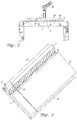
- the method generally begins with identifying a position and orientation of a specified sheet (19a) from a roll (15) including multiple sheets (19a) -(19d) on a cutting table (11) and moving a robotic sheet pickup apparatus (21) to a corresponding position to that identified for the sheet (19a).
- the pickup apparatus (21) may have a substantially planar platen (23) with a set of channels (33) coupled to a vacuum source.
- the sheet (19a) is laid upon a top surface of a tilt table, which generally is the platen (23) placed in an inverted position.
- the platen (23) is tilted from the inverted position to bring a corner of the sheet (19a) to abut against physical fences (29) and (30).
- a cutting table (11) which may be part of an automated film cutting line or conveyor system, has a flexible film substrate (13) lying on its surface and supplied, for example, from a roll (15).
- the substrate (13) is preferably a polymer film material, such as polyethylene terephthalate (PET).
- PET polyethylene terephthalate
- other sheet material including thin glass (with appropriate modifications to the supply technique), could be provided onto the table (11).
- sheets (19a)-(19d) are cut for subsequent attachment to the frame (41) of an insulating glass unit (IGU).
- IGU insulating glass unit
- the sheets (19a)-(19d) for the IGUs can be of various sizes, even within a single production run.
- the sheets (19a)-(19d) may be positioned on the cutting table (11) in any order and any orientation.
- the sheets (19a)-(19d) may be needed in order of numbering, or in any other order, and the sheets (19c)-(19d) may be arranged laterally while the sheets (19a)-(19b) are arranged longitudinally, for example.
- Efforts are typically made to plan the production of IGUs so that the sheets (19a)-(19d) can be cut with minimal waste of the substrate material (13) and therefore some variability in order that the sheets (19a)-(19d) are needed is necessary.
- Any unusable material may be stored on another roll (17) on the opposite side of the table (11) from the substrate supply (15).
- the various cut sheets (19a)-(19d) are located at various positions on the table (11). Specific selected sheets (19a) will generally be picked up individually, while leaving other cut sheets (19b)-(19d) on the table (11) and ideally in their same relative positions.
- the specific selected sheet (19a) after being picked-up, needs to be properly associated with, and aligned to, an awaiting IGU frame (41) for attachment.
- each sheet (19a)-(19d) is associated with a particular frame (41) which is also present in an associated manufacturing area or conveyor.
- the alignment of the sheet (19a) to the frame (41) may require that a determination of which dimension is arranged in which direction, so that the sheet (19a) is correctly oriented, be performed.
- an x-y coordinate system may be used to specify locations and orientations on the table (11) as indicated in FIG. 1 .
- This coordinate system is arbitrarily established by using a corner of the table (11) as origin, the length of the table (11) as an x-direction, and the across the table (11) dimension as a y-direction. This allows for one or more corners of the sheets (19a)-(19d) to be identified via (x, y) points in the coordinate system based on how the film (13) has been laid out. It should be noted that because the coordinate system is associated with the table, a specific sheet (19a) could actually change coordinates as the roll (15) is rolled or unrolled.
- one way to identify a specific sheet's (19a) location and orientation is by an (x, y)-coordinate of one corner together with an identification of the lengthwise direction of the sheet (19a).
- either edge could be identified as its "lengthwise” direction.
- the size of the sheet (19a) may also be known.
- the coordinates of each of the sheet's (19a) corners could be identified to provide its location.
- the coordinate system is necessarily arbitrary and any imposed coordinate position system where a particular point or dimension can be used to refer to a particular location on the table (11) can alternatively or additionally be used.
- the x-y coordinate system may be replaced, in an alternative embodiment, with a polar system.
- a 2-dimensional system is generally preferred as the table (11) forms a planar surface for the film (13)
- a 3-dimensional system may be used including, but not limited to, an x-y-z system, a spherical system, or a cylindrical system.
- a sheet pickup apparatus (21) is provided in the vicinity of the cutting table (11). In FIG. 1 , this is shown as a vacuum platen (23) on the end of a robotic arm (25). While the apparatus (21) will generally be mechanized to provide for automatic pickup, in an alternative embodiment the robotic arm (25) may be replaced by a simple swing arm controlled by a human operator.
- the vacuum platen (23) may have its own coordinate system based on positions on the platen (23). In order to simplify discussion herein, this will be referred to as the u-v coordinate system (to distinguish the coordinates from those of the table (11)).
- the u-v coordinate system may be aligned with the x-y coordinate system (e.g., they may have the same dimensional attributes) so that a position on one corresponds to the same position on the other should their origin points be aligned.
- the origin of the u-v coordinate system on the platen (23) may be positioned anywhere, but will often be positioned at or near the mechanical suction cup (34) or the corner of the fences (29) and (30) to simplify alignment determinations.
- a desired transformation of the table's x-y coordinate system to the platen's (23) u-v coordinate system may be provided so that the position of the sheet (19a) on the table (11) can be aligned with a particular position of the platen (23).
- the pickup apparatus (21) will provide a variety of different degrees of motion to the vacuum platen (23). This will often be full motion in all dimensions. More specifically, the platen (23) will generally be allowed to move across the table's x-y coordinates to align above a particular sheet (19a), to be rotated parallel to the u-v coordinate plane to align a particular edge of the platen (23) with a particular edge of the sheet (19a), to be rotated in a plane perpendicular to the u-v coordinate plane to invert the platen (23), and to move up and down vertically relative to the plane of the table (11) to engage the film (13) or move away from the table (11).
- the vacuum platen (23) has been moved by its robotic arm (25) to a position corresponding to that of the identified sheet (19a) and generally parallel therewith, such that the specified sheet (19a) can be lifted off of the table (11) without disturbing the other sheets (19b)-(19d).
- the platen (23) has a substantially planar vacuum pickup surface (27) including a set of parallel grooves or channels (33) coupled to a vacuum source, so that lifting the specified sheet (19a) may be performed using vacuum suction.
- the channels (33), in an embodiment, are about one inch (25.4 mm) deep, about 1 ⁇ 2 inch (12.7 mm) wide, separated by about 2 inches (50.8 mm) from neighboring channels (about 21 ⁇ 2 inches or 63.5 mm center-to-center), and up to about 13 feet (4 meters) long.
- the vacuum source is coupled to the channels (33) via a manifold (32) at one end of the channels (33).
- the selected sheet (19a) must be brought very close, for example, within about 1 ⁇ 2 inch to about % inch (12.7 to 19.05 mm) of the platen's channels (33) before the vacuum suction has any effect on the film (13).
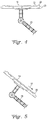
- a mechanical suction cup (34) may be provided to connect with and lift a corner of the selected sheet (19a) to within the required distance so that a particular sheet can be lifted without disturbing any neighboring sheets (19b)-(19d) even if they abut the selected sheet (19a) directly.
- the sheet (19a) will generally be edge lifted.
- one channel (33) will be initially activated so that when a corner of the sheet (19a) is positioned sufficiently close to the appropriate vacuum channel by the mechanical suction cup (34), the vacuum created by that channel (33) will serve to pull a portion of the sheet (19a) along the edge and in close proximity to the corner closer to the platen (23). As that portion moves closer to the platen (23), an adjacent portion aligned with the first is now close enough to be affected by the vacuum channel (33) and also pulled closer.
- the corner of the sheet (19a) is raised by mechanical suction cup (34), the corner is close enough to the platen (23) to initially engage an active vacuum channel (33) and as the active vacuum channel (33) pulls the corner closer, adjacent portions of the sheet (19a) are also pulled toward the vacuum channel (33).
- the portions of the roll (13) that are not part of the sheet (19a) are not lifted with the sheet (19a) which separates from the rest of the film (13) along the cuts.
- the fence elements (29) and (30) may also be used to hold the remainder of the roll against the table (11) in an embodiment.
- an array of vacuum openings or channels (33) may cover the vacuum pickup surface (27) of the platen (23). This in turn may be covered by vacuum-permeable diffuser pad (35) (shown partially peeled away).
- the vacuum channels (33) may have a wavy profile so that the pad (35) (if present) or the sheet (19a) being picked up (if the diffuser pad is not provided) do not locally slip into the channels (33).
- the channels (33) may be addressable by valves (not seen) within the manifold (32), so that specified channels (33) or rows of channels (33) are provided with vacuum suction, while other channels (33) remain inactive. This, essentially, allows each channel (33) (or subset of channels (33)) to be individually controlled.
- An edge or corner of a sheet (19a) may be picked up (as at (31) in FIG. 2 ) first, before the rest of the sheet (19a) is picked up, thereby minimizing the possibility of lift-off of adjacent sheets (19b)-(19d). Further, as the sheet (19a) is essentially picked up using a smooth sliding motion first in one direction and then the other, which is a similar motion to that used to smooth a bed sheet or rug to flatten it, there is generally very little wrinkling of the sheet (19a) being picked up and it is generally maintained in a fairly flat (planar) state.
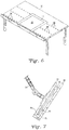
- the vacuum platen (23) is inverted by the robotic arm (25) so that the pickup surface (27) is now the top surface, with the sheet (19a) laying on that surface (27) with gravity pushing the sheet (19a) into the pickup surface (27). Only when the vacuum platen (23) is fully inverted as shown in FIG. 4 are the vacuum channels (33) turned off. The sheet (19a) then relaxes and settles onto the pickup surface (27) due to gravity. Some air may be pumped into the channels (19a) to create an air cushion upon which the sheet (19a) rests instead of having it rest on the pickup surface (27) to further remove any wrinkles.
- the platen (23) is then tilted as shown in FIG. 5 so that the sheet (19) slides down against the fence element (29).
- the platen (23) will then be tilted in an orthogonal direction so that the sheet (19) also slides down against another fence element (30) (seen in FIG. 3 ) until it is properly nestled in the corner where the two fences (29) and (30) intersect.
- both directions of tilt can be performed simultaneously. Tilting is preferably first in a widthwise direction so that the long edge of the sheet (19a) rests against one fence, and then in a lengthwise direction so that the short edge of the sheet (19a) rests against the other fence.
- the platen (23) may, in an embodiment, be rotated prior to the sheet (19a) being picked up so that the order of dimensional tilt (e.g., u then v axial direction) is always the same.
- the order of dimensional tilt e.g., u then v axial direction
- either edge could go first as there is no long edge.
- the tilting is generally just enough to allow the sheet (19a) to slide to abut the fences (29) and (30) and is insufficient to allow the sheet (19a) to wrinkle under the force of gravity due to the force imposed on the sheet (19a) by the fence (29) or (30).
- the air cushion can assist with this by lowering the frictional engagement between the sheet (19a) and pickup surface (27).
- the position of the sheet (19a) may also be verified by an optical reader capable of seeing the edge (31) and determining how close the sheet (19a) is to the corner of the fences (29) and (30). If necessary, the tilt process can be repeated to adjust the sheet (19a) position or the air cushion upon which the sheet (19a) rests can be adjusted to alter the friction between the sheet (19a) and the surface (27). Even if the sheet (19a) doesn't fully abut against the stops (29) and/or (30), the visual sensing can provide the sheet's (19a) position precisely enough for subsequent attachment to the IGU frame as slight offsets can be accounted for.
- the fence elements (29) and (30) need not actually meet.
- the "corner" of the two fences (29) and (30) could be a virtual extension of the fences (29) and (30). Leaving a slight gap at the corner has an advantage, when movement of the sheet (19a) via gravity is also assisted by an air cushion supplied through the channels (33), to allow for air to escape without wrinkling the edge of the sheet (19a) and can also assist in edge detection of the sheet (19a) by having the corner not directly abut another surface (even though the edge (31) does).
- the fences (29) and (30) preferably also have a set of slots along the plane of the pickup surface (27) to allow blown air to escape without riding over the fences (29) and (30) themselves to resist wrinkling of the sheet (19a) where it abuts the fences (29) and (30).
- a frame support (39), such as the depicted upright table or a conveyor, may be provided for the IGU frame (41).
- the frame (41) already has a first outer panel of glass (43) with spacers and adhesive applied thereto and is awaiting reception of the flexible sheet (19a) from the platen (23).
- One embodiment facilitating transport of the frames (41) could be provided with a series of rows of rollers (45) along the major surfaces of the frame support (39).
- a horizontal table is only one possibility, and other equipment for supporting a frame (41) during sheet (19a) attachment could be used instead.
- an arbitrary coordinate system can be supplied to the frame support (39) to allow for the location of the frame (41) to be communicated to the pickup apparatus (21) for alignment purposes.
- the platen (23) resumes vacuum suction of the sheet (19a) which is now located generally adjacent to the fences (29) and (30).
- the sheet (19a) can now be precisely aligned with the IGU frame (41) by aligning the sheet's (19a) coordinate position on the platen (23) with the frame's (41) coordinate position on the frame support (39). Once aligned, the sheet (19a) is placed against the IGU frame (41) by the arm (25).
- the frame (41) has an adhesive surface thereon for holding the sheet (19a) in place, the sheet (19a) adheres to the frame (41). Once attached, the vacuum from platen (23) is stopped or reversed and the sheet (19a) is released from the platen (23) and remains attached to the frame (41). The process may then be repeated for the next frame (41) and sheet (19b) combination.
- the sheet (19a) is generally planar and held generally parallel with the platen (23) when the sheet (19a) engages the frame (41), and the platen (23) is generally parallel to the frame at the same time, the sheet (19a) is applied to the frame (41) with relatively few (if any) wrinkles or waves therein.
- the IGU is ready for thermal treatment to thermally shrink the sheet (19a) while avoiding wrinkles or folds which could inhibit a resultant planar surface.
Landscapes
- Engineering & Computer Science (AREA)
- Civil Engineering (AREA)
- Structural Engineering (AREA)
- Mechanical Engineering (AREA)
- Robotics (AREA)
- Blow-Moulding Or Thermoforming Of Plastics Or The Like (AREA)
- Manipulator (AREA)
- Sheets, Magazines, And Separation Thereof (AREA)
- Casting Or Compression Moulding Of Plastics Or The Like (AREA)
- Automatic Assembly (AREA)
Applications Claiming Priority (3)
| Application Number | Priority Date | Filing Date | Title |
|---|---|---|---|
| US201361786219P | 2013-03-14 | 2013-03-14 | |
| US14/153,227 US9896289B2 (en) | 2013-03-14 | 2014-01-13 | Automated film pickup and placement method for insulating glass units |
| PCT/US2014/020151 WO2014158788A1 (en) | 2013-03-14 | 2014-03-04 | Automated film pickup and placement method for insulating glass units |
Publications (2)
| Publication Number | Publication Date |
|---|---|
| EP2971424A1 EP2971424A1 (en) | 2016-01-20 |
| EP2971424B1 true EP2971424B1 (en) | 2017-05-03 |
Family
ID=51522116
Family Applications (1)
| Application Number | Title | Priority Date | Filing Date |
|---|---|---|---|
| EP14714839.9A Not-in-force EP2971424B1 (en) | 2013-03-14 | 2014-03-04 | Automated film pickup and placement method for insulating glass units |
Country Status (10)
| Country | Link |
|---|---|
| US (1) | US9896289B2 (enExample) |
| EP (1) | EP2971424B1 (enExample) |
| JP (1) | JP2016513592A (enExample) |
| KR (1) | KR20150131228A (enExample) |
| CN (1) | CN105008649B (enExample) |
| AU (1) | AU2014241909B2 (enExample) |
| CA (1) | CA2899984A1 (enExample) |
| RU (1) | RU2015143624A (enExample) |
| TW (1) | TWI629147B (enExample) |
| WO (1) | WO2014158788A1 (enExample) |
Families Citing this family (20)
| Publication number | Priority date | Publication date | Assignee | Title |
|---|---|---|---|---|
| JP2014076522A (ja) * | 2012-10-11 | 2014-05-01 | Seiko Epson Corp | ロボットハンド及びロボット装置 |
| JP6208601B2 (ja) | 2014-03-06 | 2017-10-04 | ファナック株式会社 | ワーク位置決め機能を有するロボットハンド、ロボットシステム、及びワークの位置決め把持方法 |
| CN104289621B (zh) * | 2014-08-01 | 2018-05-01 | 徐州德坤电气科技有限公司 | 一种基于数字总线的空调器翅片总成自动胀管系统 |
| CN106672624A (zh) * | 2016-12-13 | 2017-05-17 | 惠科股份有限公司 | 一种显示面板的传送装置 |
| CN109333781B (zh) * | 2016-12-30 | 2020-09-08 | 绍兴柯桥新兴门业有限公司 | 一种用于陶瓷喯釉的输送下料一体机 |
| CN107020757B (zh) * | 2017-06-02 | 2023-02-24 | 江西海源复合材料科技股份有限公司 | 碳纤维复合材料生产线及生产方法 |
| US10195747B1 (en) * | 2017-08-03 | 2019-02-05 | General Electric Company | Multi-faced apparatus and system for automated handling of components |
| CN107717378A (zh) * | 2017-10-26 | 2018-02-23 | 江西宝群电子科技有限公司 | 一种膜片组件与机芯体装配的装置 |
| CN108081300A (zh) * | 2017-11-08 | 2018-05-29 | 江苏新光数控技术有限公司 | 一种用于玻璃搬运机械手 |
| US10486884B2 (en) * | 2017-11-30 | 2019-11-26 | JLS Automation | Vacuum packaging apparatus |
| CN110759636A (zh) * | 2018-07-25 | 2020-02-07 | 湖南巨强再生资源科技发展有限公司 | 一种微晶板自动卸料设备 |
| CN108946087B (zh) * | 2018-07-27 | 2023-07-28 | 江苏云天高胜机器人科技有限公司 | 盖片供给装置 |
| GB2592445A (en) * | 2020-02-28 | 2021-09-01 | Richard Lang Andrew | Window holding device |
| CN112591459B (zh) * | 2020-12-22 | 2025-10-28 | 深圳惠科精密工业有限公司 | 自动分料吸头装置及贴料设备 |
| CN113233195B (zh) * | 2021-04-25 | 2022-04-12 | 江南大学附属医院 | 一种病理玻片自动整理定位机及方法 |
| JP7689472B2 (ja) * | 2021-09-29 | 2025-06-06 | 芝浦メカトロニクス株式会社 | ピックアップ装置及び実装装置 |
| CN117228345A (zh) * | 2023-09-27 | 2023-12-15 | 格林策巴赫机械(嘉善)有限公司 | 电子玻璃机械手自适应堆垛方法 |
| SE547221C2 (en) | 2023-10-10 | 2025-06-10 | Hybridized As | A method and a production line for manufacturing of building elements |
| US20250237107A1 (en) * | 2024-01-22 | 2025-07-24 | Meshtec International Co., Ltd. | Security screen system and method of automated or semi-automated assembly |
| CN120397728B (zh) * | 2025-06-27 | 2025-08-22 | 苏州晟成光伏设备有限公司 | 一种柔性片材的取放装置、取放方法及玻璃上料机 |
Family Cites Families (35)
| Publication number | Priority date | Publication date | Assignee | Title |
|---|---|---|---|---|
| DE1266230B (de) | 1965-12-03 | 1968-04-11 | Rheinische Ziehglas A G | Vorrichtung zum einzelweisen Abheben von Scheiben, insbesondere Glasscheiben, von einem in etwa hochkant stehenden Stapel |
| US4121865A (en) | 1976-12-09 | 1978-10-24 | Littwin Sr Robert L | Pickup method and apparatus |
| US4335166A (en) | 1980-11-21 | 1982-06-15 | Cardinal Insulated Glass Co. | Method of manufacturing a multiple-pane insulating glass unit |
| DE3637561A1 (de) | 1985-11-18 | 1987-05-21 | Lisec Peter | Vorrichtung zum anbringen von flexiblen abstandhaltern auf glastafeln |
| FR2603566B1 (fr) * | 1986-09-08 | 1992-07-03 | Nippon Sheet Glass Co Ltd | Dispositif pour charger des produits fabriques a partir de verre en feuilles |
| US4950344A (en) | 1988-12-05 | 1990-08-21 | Lauren Manufacturing Company | Method of manufacturing multiple-pane sealed glazing units |
| DE68912608T2 (de) * | 1989-10-20 | 1994-07-14 | Sgn Soc Gen Tech Nouvelle | Polyvalente vorrichtung zum schnellen abheben von glasscheiben. |
| US5207553A (en) | 1992-02-26 | 1993-05-04 | Haruo Konagai | Suction lifting device for flat workpieces |
| US5259859A (en) | 1992-09-02 | 1993-11-09 | Ppg Industries, Inc. | Lightweight vacuum shuttle |
| ES2104109T3 (es) | 1993-04-14 | 1997-10-01 | Bystronic Masch | Instalacion para la clasificacion de material en placas. |
| AT402395B (de) | 1995-10-13 | 1997-04-25 | Lisec Peter | Vorrichtung zum umsetzen von isolierglasscheiben |
| US6069416A (en) | 1996-06-24 | 2000-05-30 | Anorad Corporation | Two-axis motor platen and method for making |
| JP4316027B2 (ja) * | 1998-07-22 | 2009-08-19 | 株式会社神戸製鋼所 | 部品の位置決め方法及びその装置 |
| JP4190065B2 (ja) | 1998-10-23 | 2008-12-03 | 日立造船株式会社 | 薄板の保持搬送方法 |
| US6345818B1 (en) * | 1998-10-26 | 2002-02-12 | Fanuc Robotics North America Inc. | Robotic manipulator having a gripping tool assembly |
| JP2000191334A (ja) * | 1998-12-25 | 2000-07-11 | Asahi Glass Co Ltd | 板ガラスの搬送装置 |
| JP4526151B2 (ja) | 2000-01-28 | 2010-08-18 | キヤノンアネルバ株式会社 | 基板処理装置の基板移載装置 |
| DE10148038A1 (de) * | 2001-09-28 | 2003-04-17 | Grenzebach Maschb Gmbh | Einrichtung zur Plattenübergabe von einem Plattenförderer auf ein Stapelgestell oder dergleichen |
| JP4197932B2 (ja) * | 2002-11-28 | 2008-12-17 | 三洋電機株式会社 | 輸送ロボットおよび輸送ロボットを採用した混成集積回路の製造方法 |
| EP1431215A1 (de) | 2002-12-19 | 2004-06-23 | Bystronic Maschinen AG | Verfahren und Vorrichtung zum beschicken einer Glasverarbeitungsanlage |
| CA2421121A1 (fr) | 2003-03-13 | 2004-09-13 | Roger Mercure | Dispositif et methode pour la valorisation et l'optimisation de panneaux a decouper |
| CA2460859A1 (en) | 2003-03-13 | 2004-09-13 | Bromer Inc. | Storage system for glass offcuts |
| DE10323234B4 (de) * | 2003-05-22 | 2008-10-30 | Webasto Ag | Verfahren zum Herstellen einer gewölbten Scheibenanordnung für ein Fahrzeug |
| TWI245731B (en) | 2003-12-26 | 2005-12-21 | Sentelic Corp | Pasting-film/testing equipment |
| DE102004032435B4 (de) * | 2004-07-05 | 2006-12-21 | Lenhardt Maschinenbau Gmbh | Verfahren und Vorrichtung zum Zusammenbauen von Isolierglasscheiben, die mit einem von Luft verschiedenen Gas gefüllt sind. |
| KR20050089731A (ko) | 2004-10-13 | 2005-09-08 | 동일파텍주식회사 | 액정표시장치용 매크로 검사장치 |
| DE102005014290A1 (de) | 2005-03-24 | 2006-09-28 | Giesecke & Devrient Gmbh | Vorrichtung für die Ausrichtung von ungeordnetem Blattgut |
| DE102005033040B3 (de) | 2005-07-15 | 2007-03-22 | Lenhardt Maschinenbau Gmbh | Vorrichtung zum Zusammenbauen von Isolierglasscheiben, die mit einem von Luft verschiedenen Gas gefüllt sind |
| JP4850721B2 (ja) | 2007-01-04 | 2012-01-11 | 株式会社日立プラントテクノロジー | フィルム貼付方法及びフィルム貼付装置 |
| DE202007004183U1 (de) * | 2007-03-16 | 2008-08-07 | Kuka Systems Gmbh | Rahmungseinrichtung |
| CN101537995B (zh) * | 2008-03-18 | 2011-10-26 | 上海力进铝质工程有限公司 | 可倾式真空负载提升机 |
| JP5576709B2 (ja) * | 2010-05-13 | 2014-08-20 | リンテック株式会社 | 支持装置および支持方法ならびに搬送装置および搬送方法 |
| TWM415902U (en) | 2011-04-22 | 2011-11-11 | Chien Yutsai Entpr Ltd | Drawing and shifting device for flexible sheet |
| CN202542468U (zh) * | 2011-12-31 | 2012-11-21 | 佛山市高明南亮玻璃制品有限公司 | 一种玻璃上片台的双边上片装置 |
| TWM444982U (zh) | 2012-09-17 | 2013-01-11 | Zheng-Zhong Hong | 膠膜片材之對位裝置 |
-
2014
- 2014-01-13 US US14/153,227 patent/US9896289B2/en not_active Expired - Fee Related
- 2014-03-04 JP JP2016500581A patent/JP2016513592A/ja active Pending
- 2014-03-04 CN CN201480014919.4A patent/CN105008649B/zh not_active Expired - Fee Related
- 2014-03-04 WO PCT/US2014/020151 patent/WO2014158788A1/en not_active Ceased
- 2014-03-04 KR KR1020157028926A patent/KR20150131228A/ko not_active Withdrawn
- 2014-03-04 AU AU2014241909A patent/AU2014241909B2/en not_active Ceased
- 2014-03-04 EP EP14714839.9A patent/EP2971424B1/en not_active Not-in-force
- 2014-03-04 RU RU2015143624A patent/RU2015143624A/ru not_active Application Discontinuation
- 2014-03-04 CA CA2899984A patent/CA2899984A1/en not_active Abandoned
- 2014-03-13 TW TW103109172A patent/TWI629147B/zh not_active IP Right Cessation
Also Published As
| Publication number | Publication date |
|---|---|
| KR20150131228A (ko) | 2015-11-24 |
| TW201501887A (zh) | 2015-01-16 |
| WO2014158788A1 (en) | 2014-10-02 |
| EP2971424A1 (en) | 2016-01-20 |
| US9896289B2 (en) | 2018-02-20 |
| RU2015143624A (ru) | 2017-04-26 |
| AU2014241909B2 (en) | 2017-06-22 |
| CN105008649B (zh) | 2017-06-23 |
| CN105008649A (zh) | 2015-10-28 |
| RU2015143624A3 (enExample) | 2018-03-19 |
| JP2016513592A (ja) | 2016-05-16 |
| CA2899984A1 (en) | 2014-10-02 |
| US20140261962A1 (en) | 2014-09-18 |
| TWI629147B (zh) | 2018-07-11 |
| AU2014241909A1 (en) | 2015-10-29 |
Similar Documents
| Publication | Publication Date | Title |
|---|---|---|
| EP2971424B1 (en) | Automated film pickup and placement method for insulating glass units | |
| US20200411450A1 (en) | Glass substrate and display device comprising the same | |
| US8919406B2 (en) | Bonding apparatus | |
| JP5821664B2 (ja) | 貼り合わせ装置、及び貼り合わせ方法 | |
| TW200947619A (en) | Substrate-cutting system, substrate-producing apparatus, substrate-scribing method, and substrate-cutting method | |
| CN105579654B (zh) | 输送设备 | |
| US9186876B1 (en) | Masking technology | |
| CN107745187B (zh) | 压膜治具和激光切膜系统 | |
| JPS6227246A (ja) | 可撓性プラスチック材料のシートの把持・移送方法及び装置 | |
| JP5877761B2 (ja) | 保持装置、搬送システム及び保持方法 | |
| CN110391155A (zh) | 附着基板的方法和用于附着基板的设备 | |
| JP2003197724A (ja) | 貼付けウエハ分離装置および貼付けウエハ分離方法 | |
| TW201607764A (zh) | 積層體之剝離裝置及剝離方法、與電子裝置之製造方法 | |
| TWI659847B (zh) | 積層體之剝離裝置及剝離方法以及電子元件之製造方法 | |
| WO2013177818A1 (zh) | 真空贴合机及其工作方法 | |
| CN101128294A (zh) | 脆性材料制板切割方法及其设备 | |
| JP2006327819A (ja) | ガラス板の移載装置および移載方法 | |
| WO2006136523A3 (en) | Support and handling device, particularly for glass panes or panels | |
| KR100934361B1 (ko) | 기판처리장치 | |
| JPH11235689A (ja) | 薄板の保持搬送装置 | |
| WO2015079746A1 (ja) | 板ガラスの積層方法及びその積層装置 | |
| KR101531565B1 (ko) | 흡음패널용 장식 필름 부착장치 및 이를 이용한 흡음패널용 장식 필름 부착방법 | |
| CN215046783U (zh) | 一种面板的自动夹取定位装置 | |
| WO2021108154A1 (en) | Laminating system | |
| JPH11138736A (ja) | フィルム張付装置 |
Legal Events
| Date | Code | Title | Description |
|---|---|---|---|
| PUAI | Public reference made under article 153(3) epc to a published international application that has entered the european phase |
Free format text: ORIGINAL CODE: 0009012 |
|
| 17P | Request for examination filed |
Effective date: 20151014 |
|
| AK | Designated contracting states |
Kind code of ref document: A1 Designated state(s): AL AT BE BG CH CY CZ DE DK EE ES FI FR GB GR HR HU IE IS IT LI LT LU LV MC MK MT NL NO PL PT RO RS SE SI SK SM TR |
|
| AX | Request for extension of the european patent |
Extension state: BA ME |
|
| DAX | Request for extension of the european patent (deleted) | ||
| GRAP | Despatch of communication of intention to grant a patent |
Free format text: ORIGINAL CODE: EPIDOSNIGR1 |
|
| STAA | Information on the status of an ep patent application or granted ep patent |
Free format text: STATUS: GRANT OF PATENT IS INTENDED |
|
| INTG | Intention to grant announced |
Effective date: 20161128 |
|
| GRAS | Grant fee paid |
Free format text: ORIGINAL CODE: EPIDOSNIGR3 |
|
| GRAA | (expected) grant |
Free format text: ORIGINAL CODE: 0009210 |
|
| STAA | Information on the status of an ep patent application or granted ep patent |
Free format text: STATUS: THE PATENT HAS BEEN GRANTED |
|
| AK | Designated contracting states |
Kind code of ref document: B1 Designated state(s): AL AT BE BG CH CY CZ DE DK EE ES FI FR GB GR HR HU IE IS IT LI LT LU LV MC MK MT NL NO PL PT RO RS SE SI SK SM TR |
|
| REG | Reference to a national code |
Ref country code: GB Ref legal event code: FG4D |
|
| REG | Reference to a national code |
Ref country code: AT Ref legal event code: REF Ref document number: 890200 Country of ref document: AT Kind code of ref document: T Effective date: 20170515 Ref country code: CH Ref legal event code: EP |
|
| REG | Reference to a national code |
Ref country code: IE Ref legal event code: FG4D |
|
| REG | Reference to a national code |
Ref country code: DE Ref legal event code: R096 Ref document number: 602014009332 Country of ref document: DE |
|
| REG | Reference to a national code |
Ref country code: NL Ref legal event code: MP Effective date: 20170503 |
|
| REG | Reference to a national code |
Ref country code: AT Ref legal event code: MK05 Ref document number: 890200 Country of ref document: AT Kind code of ref document: T Effective date: 20170503 |
|
| REG | Reference to a national code |
Ref country code: LT Ref legal event code: MG4D |
|
| PG25 | Lapsed in a contracting state [announced via postgrant information from national office to epo] |
Ref country code: FI Free format text: LAPSE BECAUSE OF FAILURE TO SUBMIT A TRANSLATION OF THE DESCRIPTION OR TO PAY THE FEE WITHIN THE PRESCRIBED TIME-LIMIT Effective date: 20170503 Ref country code: NO Free format text: LAPSE BECAUSE OF FAILURE TO SUBMIT A TRANSLATION OF THE DESCRIPTION OR TO PAY THE FEE WITHIN THE PRESCRIBED TIME-LIMIT Effective date: 20170803 Ref country code: AT Free format text: LAPSE BECAUSE OF FAILURE TO SUBMIT A TRANSLATION OF THE DESCRIPTION OR TO PAY THE FEE WITHIN THE PRESCRIBED TIME-LIMIT Effective date: 20170503 Ref country code: GR Free format text: LAPSE BECAUSE OF FAILURE TO SUBMIT A TRANSLATION OF THE DESCRIPTION OR TO PAY THE FEE WITHIN THE PRESCRIBED TIME-LIMIT Effective date: 20170804 Ref country code: ES Free format text: LAPSE BECAUSE OF FAILURE TO SUBMIT A TRANSLATION OF THE DESCRIPTION OR TO PAY THE FEE WITHIN THE PRESCRIBED TIME-LIMIT Effective date: 20170503 Ref country code: LT Free format text: LAPSE BECAUSE OF FAILURE TO SUBMIT A TRANSLATION OF THE DESCRIPTION OR TO PAY THE FEE WITHIN THE PRESCRIBED TIME-LIMIT Effective date: 20170503 Ref country code: HR Free format text: LAPSE BECAUSE OF FAILURE TO SUBMIT A TRANSLATION OF THE DESCRIPTION OR TO PAY THE FEE WITHIN THE PRESCRIBED TIME-LIMIT Effective date: 20170503 |
|
| PG25 | Lapsed in a contracting state [announced via postgrant information from national office to epo] |
Ref country code: BG Free format text: LAPSE BECAUSE OF FAILURE TO SUBMIT A TRANSLATION OF THE DESCRIPTION OR TO PAY THE FEE WITHIN THE PRESCRIBED TIME-LIMIT Effective date: 20170803 Ref country code: PL Free format text: LAPSE BECAUSE OF FAILURE TO SUBMIT A TRANSLATION OF THE DESCRIPTION OR TO PAY THE FEE WITHIN THE PRESCRIBED TIME-LIMIT Effective date: 20170503 Ref country code: RS Free format text: LAPSE BECAUSE OF FAILURE TO SUBMIT A TRANSLATION OF THE DESCRIPTION OR TO PAY THE FEE WITHIN THE PRESCRIBED TIME-LIMIT Effective date: 20170503 Ref country code: LV Free format text: LAPSE BECAUSE OF FAILURE TO SUBMIT A TRANSLATION OF THE DESCRIPTION OR TO PAY THE FEE WITHIN THE PRESCRIBED TIME-LIMIT Effective date: 20170503 Ref country code: NL Free format text: LAPSE BECAUSE OF FAILURE TO SUBMIT A TRANSLATION OF THE DESCRIPTION OR TO PAY THE FEE WITHIN THE PRESCRIBED TIME-LIMIT Effective date: 20170503 Ref country code: SE Free format text: LAPSE BECAUSE OF FAILURE TO SUBMIT A TRANSLATION OF THE DESCRIPTION OR TO PAY THE FEE WITHIN THE PRESCRIBED TIME-LIMIT Effective date: 20170503 Ref country code: IS Free format text: LAPSE BECAUSE OF FAILURE TO SUBMIT A TRANSLATION OF THE DESCRIPTION OR TO PAY THE FEE WITHIN THE PRESCRIBED TIME-LIMIT Effective date: 20170903 |
|
| PG25 | Lapsed in a contracting state [announced via postgrant information from national office to epo] |
Ref country code: DK Free format text: LAPSE BECAUSE OF FAILURE TO SUBMIT A TRANSLATION OF THE DESCRIPTION OR TO PAY THE FEE WITHIN THE PRESCRIBED TIME-LIMIT Effective date: 20170503 Ref country code: EE Free format text: LAPSE BECAUSE OF FAILURE TO SUBMIT A TRANSLATION OF THE DESCRIPTION OR TO PAY THE FEE WITHIN THE PRESCRIBED TIME-LIMIT Effective date: 20170503 Ref country code: SK Free format text: LAPSE BECAUSE OF FAILURE TO SUBMIT A TRANSLATION OF THE DESCRIPTION OR TO PAY THE FEE WITHIN THE PRESCRIBED TIME-LIMIT Effective date: 20170503 Ref country code: RO Free format text: LAPSE BECAUSE OF FAILURE TO SUBMIT A TRANSLATION OF THE DESCRIPTION OR TO PAY THE FEE WITHIN THE PRESCRIBED TIME-LIMIT Effective date: 20170503 Ref country code: CZ Free format text: LAPSE BECAUSE OF FAILURE TO SUBMIT A TRANSLATION OF THE DESCRIPTION OR TO PAY THE FEE WITHIN THE PRESCRIBED TIME-LIMIT Effective date: 20170503 |
|
| REG | Reference to a national code |
Ref country code: DE Ref legal event code: R097 Ref document number: 602014009332 Country of ref document: DE |
|
| REG | Reference to a national code |
Ref country code: FR Ref legal event code: PLFP Year of fee payment: 5 |
|
| PG25 | Lapsed in a contracting state [announced via postgrant information from national office to epo] |
Ref country code: IT Free format text: LAPSE BECAUSE OF FAILURE TO SUBMIT A TRANSLATION OF THE DESCRIPTION OR TO PAY THE FEE WITHIN THE PRESCRIBED TIME-LIMIT Effective date: 20170503 Ref country code: SM Free format text: LAPSE BECAUSE OF FAILURE TO SUBMIT A TRANSLATION OF THE DESCRIPTION OR TO PAY THE FEE WITHIN THE PRESCRIBED TIME-LIMIT Effective date: 20170503 |
|
| PLBE | No opposition filed within time limit |
Free format text: ORIGINAL CODE: 0009261 |
|
| STAA | Information on the status of an ep patent application or granted ep patent |
Free format text: STATUS: NO OPPOSITION FILED WITHIN TIME LIMIT |
|
| 26N | No opposition filed |
Effective date: 20180206 |
|
| PGFP | Annual fee paid to national office [announced via postgrant information from national office to epo] |
Ref country code: DE Payment date: 20180308 Year of fee payment: 5 |
|
| PG25 | Lapsed in a contracting state [announced via postgrant information from national office to epo] |
Ref country code: SI Free format text: LAPSE BECAUSE OF FAILURE TO SUBMIT A TRANSLATION OF THE DESCRIPTION OR TO PAY THE FEE WITHIN THE PRESCRIBED TIME-LIMIT Effective date: 20170503 |
|
| PGFP | Annual fee paid to national office [announced via postgrant information from national office to epo] |
Ref country code: FR Payment date: 20180223 Year of fee payment: 5 Ref country code: BE Payment date: 20180315 Year of fee payment: 5 |
|
| REG | Reference to a national code |
Ref country code: CH Ref legal event code: PL |
|
| GBPC | Gb: european patent ceased through non-payment of renewal fee |
Effective date: 20180304 |
|
| PG25 | Lapsed in a contracting state [announced via postgrant information from national office to epo] |
Ref country code: MC Free format text: LAPSE BECAUSE OF FAILURE TO SUBMIT A TRANSLATION OF THE DESCRIPTION OR TO PAY THE FEE WITHIN THE PRESCRIBED TIME-LIMIT Effective date: 20170503 |
|
| REG | Reference to a national code |
Ref country code: IE Ref legal event code: MM4A |
|
| PG25 | Lapsed in a contracting state [announced via postgrant information from national office to epo] |
Ref country code: LU Free format text: LAPSE BECAUSE OF NON-PAYMENT OF DUE FEES Effective date: 20180304 |
|
| PG25 | Lapsed in a contracting state [announced via postgrant information from national office to epo] |
Ref country code: IE Free format text: LAPSE BECAUSE OF NON-PAYMENT OF DUE FEES Effective date: 20180304 |
|
| PG25 | Lapsed in a contracting state [announced via postgrant information from national office to epo] |
Ref country code: GB Free format text: LAPSE BECAUSE OF NON-PAYMENT OF DUE FEES Effective date: 20180304 Ref country code: CH Free format text: LAPSE BECAUSE OF NON-PAYMENT OF DUE FEES Effective date: 20180331 Ref country code: LI Free format text: LAPSE BECAUSE OF NON-PAYMENT OF DUE FEES Effective date: 20180331 |
|
| REG | Reference to a national code |
Ref country code: DE Ref legal event code: R119 Ref document number: 602014009332 Country of ref document: DE |
|
| REG | Reference to a national code |
Ref country code: BE Ref legal event code: MM Effective date: 20190331 |
|
| PG25 | Lapsed in a contracting state [announced via postgrant information from national office to epo] |
Ref country code: DE Free format text: LAPSE BECAUSE OF NON-PAYMENT OF DUE FEES Effective date: 20191001 Ref country code: MT Free format text: LAPSE BECAUSE OF NON-PAYMENT OF DUE FEES Effective date: 20180304 |
|
| PG25 | Lapsed in a contracting state [announced via postgrant information from national office to epo] |
Ref country code: FR Free format text: LAPSE BECAUSE OF NON-PAYMENT OF DUE FEES Effective date: 20190331 Ref country code: BE Free format text: LAPSE BECAUSE OF NON-PAYMENT OF DUE FEES Effective date: 20190331 |
|
| PG25 | Lapsed in a contracting state [announced via postgrant information from national office to epo] |
Ref country code: TR Free format text: LAPSE BECAUSE OF FAILURE TO SUBMIT A TRANSLATION OF THE DESCRIPTION OR TO PAY THE FEE WITHIN THE PRESCRIBED TIME-LIMIT Effective date: 20170503 |
|
| PG25 | Lapsed in a contracting state [announced via postgrant information from national office to epo] |
Ref country code: PT Free format text: LAPSE BECAUSE OF FAILURE TO SUBMIT A TRANSLATION OF THE DESCRIPTION OR TO PAY THE FEE WITHIN THE PRESCRIBED TIME-LIMIT Effective date: 20170503 |
|
| PG25 | Lapsed in a contracting state [announced via postgrant information from national office to epo] |
Ref country code: CY Free format text: LAPSE BECAUSE OF FAILURE TO SUBMIT A TRANSLATION OF THE DESCRIPTION OR TO PAY THE FEE WITHIN THE PRESCRIBED TIME-LIMIT Effective date: 20170503 Ref country code: HU Free format text: LAPSE BECAUSE OF FAILURE TO SUBMIT A TRANSLATION OF THE DESCRIPTION OR TO PAY THE FEE WITHIN THE PRESCRIBED TIME-LIMIT; INVALID AB INITIO Effective date: 20140304 Ref country code: MK Free format text: LAPSE BECAUSE OF NON-PAYMENT OF DUE FEES Effective date: 20170503 |
|
| PG25 | Lapsed in a contracting state [announced via postgrant information from national office to epo] |
Ref country code: AL Free format text: LAPSE BECAUSE OF FAILURE TO SUBMIT A TRANSLATION OF THE DESCRIPTION OR TO PAY THE FEE WITHIN THE PRESCRIBED TIME-LIMIT Effective date: 20170503 |