EP2959986B1 - Method and apparatus for manufacturing a pipe element having shoulder, groove and bead - Google Patents
Method and apparatus for manufacturing a pipe element having shoulder, groove and bead Download PDFInfo
- Publication number
- EP2959986B1 EP2959986B1 EP15176201.0A EP15176201A EP2959986B1 EP 2959986 B1 EP2959986 B1 EP 2959986B1 EP 15176201 A EP15176201 A EP 15176201A EP 2959986 B1 EP2959986 B1 EP 2959986B1
- Authority
- EP
- European Patent Office
- Prior art keywords
- segment
- roller
- outer diameter
- pipe element
- rollers
- Prior art date
- Legal status (The legal status is an assumption and is not a legal conclusion. Google has not performed a legal analysis and makes no representation as to the accuracy of the status listed.)
- Not-in-force
Links
Images


Classifications
-
- F—MECHANICAL ENGINEERING; LIGHTING; HEATING; WEAPONS; BLASTING
- F16—ENGINEERING ELEMENTS AND UNITS; GENERAL MEASURES FOR PRODUCING AND MAINTAINING EFFECTIVE FUNCTIONING OF MACHINES OR INSTALLATIONS; THERMAL INSULATION IN GENERAL
- F16L—PIPES; JOINTS OR FITTINGS FOR PIPES; SUPPORTS FOR PIPES, CABLES OR PROTECTIVE TUBING; MEANS FOR THERMAL INSULATION IN GENERAL
- F16L21/00—Joints with sleeve or socket
- F16L21/06—Joints with sleeve or socket with a divided sleeve or ring clamping around the pipe-ends
-
- F—MECHANICAL ENGINEERING; LIGHTING; HEATING; WEAPONS; BLASTING
- F16—ENGINEERING ELEMENTS AND UNITS; GENERAL MEASURES FOR PRODUCING AND MAINTAINING EFFECTIVE FUNCTIONING OF MACHINES OR INSTALLATIONS; THERMAL INSULATION IN GENERAL
- F16L—PIPES; JOINTS OR FITTINGS FOR PIPES; SUPPORTS FOR PIPES, CABLES OR PROTECTIVE TUBING; MEANS FOR THERMAL INSULATION IN GENERAL
- F16L21/00—Joints with sleeve or socket
- F16L21/02—Joints with sleeve or socket with elastic sealing rings between pipe and sleeve or between pipe and socket, e.g. with rolling or other prefabricated profiled rings
- F16L21/022—Joints with sleeve or socket with elastic sealing rings between pipe and sleeve or between pipe and socket, e.g. with rolling or other prefabricated profiled rings used with sleeves or nipples for pipes of the same diameter, or with reduction pieces
-
- B—PERFORMING OPERATIONS; TRANSPORTING
- B21—MECHANICAL METAL-WORKING WITHOUT ESSENTIALLY REMOVING MATERIAL; PUNCHING METAL
- B21B—ROLLING OF METAL
- B21B23/00—Tube-rolling not restricted to methods provided for in only one of groups B21B17/00, B21B19/00, B21B21/00, e.g. combined processes planetary tube rolling, auxiliary arrangements, e.g. lubricating, special tube blanks, continuous casting combined with tube rolling
-
- B—PERFORMING OPERATIONS; TRANSPORTING
- B21—MECHANICAL METAL-WORKING WITHOUT ESSENTIALLY REMOVING MATERIAL; PUNCHING METAL
- B21D—WORKING OR PROCESSING OF SHEET METAL OR METAL TUBES, RODS OR PROFILES WITHOUT ESSENTIALLY REMOVING MATERIAL; PUNCHING METAL
- B21D15/00—Corrugating tubes
- B21D15/04—Corrugating tubes transversely, e.g. helically
- B21D15/06—Corrugating tubes transversely, e.g. helically annularly
-
- B—PERFORMING OPERATIONS; TRANSPORTING
- B21—MECHANICAL METAL-WORKING WITHOUT ESSENTIALLY REMOVING MATERIAL; PUNCHING METAL
- B21D—WORKING OR PROCESSING OF SHEET METAL OR METAL TUBES, RODS OR PROFILES WITHOUT ESSENTIALLY REMOVING MATERIAL; PUNCHING METAL
- B21D17/00—Forming single grooves in sheet metal or tubular or hollow articles
- B21D17/04—Forming single grooves in sheet metal or tubular or hollow articles by rolling
-
- B—PERFORMING OPERATIONS; TRANSPORTING
- B21—MECHANICAL METAL-WORKING WITHOUT ESSENTIALLY REMOVING MATERIAL; PUNCHING METAL
- B21D—WORKING OR PROCESSING OF SHEET METAL OR METAL TUBES, RODS OR PROFILES WITHOUT ESSENTIALLY REMOVING MATERIAL; PUNCHING METAL
- B21D22/00—Shaping without cutting, by stamping, spinning, or deep-drawing
- B21D22/14—Spinning
- B21D22/16—Spinning over shaping mandrels or formers
-
- B—PERFORMING OPERATIONS; TRANSPORTING
- B21—MECHANICAL METAL-WORKING WITHOUT ESSENTIALLY REMOVING MATERIAL; PUNCHING METAL
- B21D—WORKING OR PROCESSING OF SHEET METAL OR METAL TUBES, RODS OR PROFILES WITHOUT ESSENTIALLY REMOVING MATERIAL; PUNCHING METAL
- B21D39/00—Application of procedures in order to connect objects or parts, e.g. coating with sheet metal otherwise than by plating; Tube expanders
- B21D39/04—Application of procedures in order to connect objects or parts, e.g. coating with sheet metal otherwise than by plating; Tube expanders of tubes with tubes; of tubes with rods
- B21D39/046—Connecting tubes to tube-like fittings
-
- B—PERFORMING OPERATIONS; TRANSPORTING
- B21—MECHANICAL METAL-WORKING WITHOUT ESSENTIALLY REMOVING MATERIAL; PUNCHING METAL
- B21D—WORKING OR PROCESSING OF SHEET METAL OR METAL TUBES, RODS OR PROFILES WITHOUT ESSENTIALLY REMOVING MATERIAL; PUNCHING METAL
- B21D41/00—Application of procedures in order to alter the diameter of tube ends
- B21D41/02—Enlarging
- B21D41/021—Enlarging by means of tube-flaring hand tools
- B21D41/023—Enlarging by means of tube-flaring hand tools comprising rolling elements
-
- F—MECHANICAL ENGINEERING; LIGHTING; HEATING; WEAPONS; BLASTING
- F16—ENGINEERING ELEMENTS AND UNITS; GENERAL MEASURES FOR PRODUCING AND MAINTAINING EFFECTIVE FUNCTIONING OF MACHINES OR INSTALLATIONS; THERMAL INSULATION IN GENERAL
- F16L—PIPES; JOINTS OR FITTINGS FOR PIPES; SUPPORTS FOR PIPES, CABLES OR PROTECTIVE TUBING; MEANS FOR THERMAL INSULATION IN GENERAL
- F16L17/00—Joints with packing adapted to sealing by fluid pressure
- F16L17/02—Joints with packing adapted to sealing by fluid pressure with sealing rings arranged between outer surface of pipe and inner surface of sleeve or socket
- F16L17/025—Joints with packing adapted to sealing by fluid pressure with sealing rings arranged between outer surface of pipe and inner surface of sleeve or socket the sealing rings having radially directed ribs
-
- F—MECHANICAL ENGINEERING; LIGHTING; HEATING; WEAPONS; BLASTING
- F16—ENGINEERING ELEMENTS AND UNITS; GENERAL MEASURES FOR PRODUCING AND MAINTAINING EFFECTIVE FUNCTIONING OF MACHINES OR INSTALLATIONS; THERMAL INSULATION IN GENERAL
- F16L—PIPES; JOINTS OR FITTINGS FOR PIPES; SUPPORTS FOR PIPES, CABLES OR PROTECTIVE TUBING; MEANS FOR THERMAL INSULATION IN GENERAL
- F16L17/00—Joints with packing adapted to sealing by fluid pressure
- F16L17/02—Joints with packing adapted to sealing by fluid pressure with sealing rings arranged between outer surface of pipe and inner surface of sleeve or socket
- F16L17/04—Joints with packing adapted to sealing by fluid pressure with sealing rings arranged between outer surface of pipe and inner surface of sleeve or socket with longitudinally split or divided sleeve
-
- F—MECHANICAL ENGINEERING; LIGHTING; HEATING; WEAPONS; BLASTING
- F16—ENGINEERING ELEMENTS AND UNITS; GENERAL MEASURES FOR PRODUCING AND MAINTAINING EFFECTIVE FUNCTIONING OF MACHINES OR INSTALLATIONS; THERMAL INSULATION IN GENERAL
- F16L—PIPES; JOINTS OR FITTINGS FOR PIPES; SUPPORTS FOR PIPES, CABLES OR PROTECTIVE TUBING; MEANS FOR THERMAL INSULATION IN GENERAL
- F16L23/00—Flanged joints
- F16L23/04—Flanged joints the flanges being connected by members tensioned in the radial plane
- F16L23/08—Flanged joints the flanges being connected by members tensioned in the radial plane connection by tangentially arranged pin and nut
-
- F—MECHANICAL ENGINEERING; LIGHTING; HEATING; WEAPONS; BLASTING
- F16—ENGINEERING ELEMENTS AND UNITS; GENERAL MEASURES FOR PRODUCING AND MAINTAINING EFFECTIVE FUNCTIONING OF MACHINES OR INSTALLATIONS; THERMAL INSULATION IN GENERAL
- F16L—PIPES; JOINTS OR FITTINGS FOR PIPES; SUPPORTS FOR PIPES, CABLES OR PROTECTIVE TUBING; MEANS FOR THERMAL INSULATION IN GENERAL
- F16L25/00—Constructive types of pipe joints not provided for in groups F16L13/00 - F16L23/00 ; Details of pipe joints not otherwise provided for, e.g. electrically conducting or insulating means
- F16L25/12—Joints for pipes being spaced apart axially
Definitions
- This invention relates to an apparatus for making pipe elements joined together by mechanical couplings and methods for making such pipe elements with that apparatus.
- Such couplings comprise two or more coupling segments joined in end to end relation by threaded fasteners.
- the segments surround a central space which receives the pipe elements.
- Each segment has a pair of arcuate projections known as "keys" which engage the outer surfaces of the pipe elements.
- the keys are often received in circumferential grooves in the pipe elements which provide a positive mechanical engagement against bending and axial loads applied to the joint.
- Each segment also defines a channel between its pair of arcuate projections which receives a ring-shaped gasket. The gasket is typically compressed between the segments and the pipe elements to effect a fluid tight joint.
- Circumferential grooves are advantageously formed by cold working the sidewall of the pipe element because, unlike cut grooves, material is not removed from the pipe sidewall and thus thinner walled pipe elements may be grooved by the cold working process. It is advantageous to use thinner walled pipe elements for weight and cost savings in high pressure and /or high load applications.
- prior art cold working methods and pipe designs do not produce coupling and pipe element engagement features adequate for high loads and pressures sustainable by comparable cut groove systems used on thicker walled pipe elements.
- There are clear advantages to be had through improvements to the design and manufacture of thin walled grooved pipe elements by cold working which will allow thin walled grooved pipe elements to be joined by mechanical couplings and used in high pressure/high load applications.
- US 6 196 039 B1 discloses groove rollers, an outside roller with a peripheral surface that includes a first protrusion configured to form the groove, and a second protrusion, an inside roller has a peripheral surface that includes a notch configured to receive the first protrusion, and has a second notch configured to receive the second protrusion.
- the present invention is directed to device for forming the ends of a pipe element according to claim 1.
- the device comprising a first roller and second roller (80) for imparting a shape to a sidewall of a pipe element, wherein said first roller rotates about an axis.
- the first roller comprises a first segment having a first outer diameter and a second segment positioned contiguous with the first segment.
- the second segment has a second outer diameter smaller than the first outer diameter.
- a third segment is positioned contiguous with the second segment and has a third outer diameter larger than the second outer diameter.
- An eighth segment is positioned contiguous with the third segment and has an eighth outer diameter smaller than the second outer diameter.
- a ninth segment is positioned contiguous with the eighth segment and has an eighth outer diameter approximately equal to the second outer diameter.
- the second roller comprises a fourth segment having a fourth outer diameter and a fifth segment positioned contiguous with said fourth segment and having a fifth outer diameter greater than the fourth outer diameter.
- a sixth segment is positioned contiguous with said fifth segment and has an sixth outer diameter less than the fifth outer diameter.
- a seventh segment is positioned contiguous with said sixth segment and has a seventh outer diameter approximately equal to the fifth outer diameter.
- the fifth segment comprises a first annular surface positioned adjacent to the fourth segment and oriented substantially perpendicularly to the second axis, and a second annular surface positioned adjacent to the sixth segment and oriented angularly with respect to the second axis.
- the device comprises a support frame.
- the first roller is mounted on the support frame and is rotatable about a first axis.
- the first roller is adapted to engage an inner surface of the pipe element.
- Means for rotating the first roller about the first axis are also provided.
- the second roller is mounted on the support frame and is rotatable about a second axis oriented substantially parallel to the first axis.
- the second roller is movable toward and away from the first roller and is adapted to engage an outer surface of the pipe element.
- Means for moving the second roller relatively to the first roller for compressing the sidewall while the rollers rotate are also provided.
- the rollers are arranged relatively to one another on the support frame such that: the fourth segment is aligned with the first segment; the fifth segment is aligned with the second segment; the sixth segment is aligned with the third segment.
- the rotating means may comprise an electric motor or a hydraulic motor operated by a pump, and the moving means may comprise a hydraulic actuator or a jackscrew by way of example.
- the invention further encompasses a method of imparting a shape to the sidewall of a pipe element having an inner surface and an outer surface according to claim 8 by using the device according to the invention.
- the method comprises: contacting the inner surface of the pipe element at a first point on the first segment of the first roller; contacting the outer surface of the pipe element at a third point on the fifth segment of the second roller; rotating one of the first and second rollers thereby causing the other of the first and second rollers and the pipe element to rotate, the first roller circumferentially traverses the inner surface of the pipe element, and the second roller circumferentially traverses the outer surface of the pipe element; moving one of the first and second rollers toward the other of the first and second rollers and deforming the sidewall of the pipe element through contact between the inner surface of the pipe element and the first and third segments of the first roller, and contact between the outer surface of the pipe element and the fifth and seventh segments of the second roller; continue moving one of the first and second rollers toward the other of the first and second rollers
- pipe element means any tubular structure, including, for example, pipe stock 10 as shown in Figure 1 , as well as the tubular portion 12 of a fluid handling or control component such as the valve 14 shown in Figure 2 .
- Other components such as pumps and strainers, as well as fittings such as tees, elbows, bends and reducers are also included as having or comprising "pipe elements" as defined herein.
- pipe element 10 has an outer diameter 16 which passes through a point on a longitudinal axis 18 at the pipe element's center of curvature. At least one end 20 of pipe element 10 is configured to receive a key of a mechanical coupling (not shown), the configuration comprising a shoulder 22 positioned at the end 20, a groove 24 positioned adjacent to the shoulder 22, and a bead 26 positioned contiguous with the groove 24.
- shoulder 22 extends circumferentially around the pipe element and has an outwardly facing surface 28.
- Surface 28 has an outer diameter 30 that is greater than the outer diameter 16 of the pipe element 10 excluding the shoulder.
- Shoulder 30 also has an outwardly facing curved surface 32.
- Curved surface 32 also extends circumferentially around the pipe element and has a center of curvature on an axis 34 oriented perpendicular to the longitudinal axis 18 of the pipe element 10.
- axis 34 is shown perpendicular to the viewing plane and is therefore seen end on.
- Groove 24 is defined by a first side surface 36 which is positioned contiguous with the curved surface 32 of the shoulder 30.
- Side surface 36 may be oriented angularly.
- the orientation angle 41 may range from about 80° to about 85° with respect to the longitudinal axis 18.
- the side surface 36 maybe oriented substantially perpendicularly to longitudinal axis 18.
- substantially perpendicularly refers to an angular orientation which may not be exactly perpendicular, but is established as close as practicable in view of manufacturing practices and tolerances. Perpendicular orientation of the first side surface 36 stiffens the pipe element radially and helps it maintain its roundness.
- a second side surface 38 further defines the groove 24.
- Second side surface 38 is positioned in spaced apart relation to the first side surface 36 and is oriented angularly with respect to the longitudinal axis 18.
- Side surface 38 may have an orientation angle 40 from about 40° to about 70° or about 45° to about 65°. In the particular embodiment shown in Figure 1 , orientation angle 40 is about 55° which is considered advantageous when the groove receives keys of a mechanical coupling as shown in Figures 3-6 .
- a floor surface 42 extends between the first side surface 36 and the second side surface 38 of groove 24.
- the floor surface 42 is substantially parallel to the longitudinal axis 18 and has an outer diameter 44 which is less than the outer diameter 16 of the pipe element excluding the groove.
- the groove 24 also has an inner diameter 17 which, in the embodiment shown in Figure 1 , is approximately equal to the inner diameter 19 of the pipe element 10.
- Bead 26 is positioned contiguous with the second side surface 38 of the groove 24 and also extends circumferentially around the pipe element.
- the bead 26 projects outwardly away from axis 18 and has an apex 46 with an outer diameter 48 greater than the outer diameter 16 of the pipe element excluding the bead.
- the diameter 48 of the apex 46 is less than the outer diameter 30 of shoulder 22. Bead 26 increases the radial stiffness of the pipe element and thereby helps maintain its roundness.
- a beadless pipe element embodiment 10a is also feasible. Similar to the embodiment 10 shown in Figure 1 , for the embodiment 10a in Figure 1A the floor surface 42 is substantially parallel to the longitudinal axis 18 and has an outer diameter 44 which is less than the outer diameter 16 of the pipe element excluding the groove. The groove 24 also has an inner diameter 17 which is approximately equal to the inner diameter 19 of the pipe element 10a.
- the configuration of the end of the pipe element 10 is the same at both ends (not shown for clarity), but other configurations are also feasible wherein the ends may be dissimilar.
- the pipe elements 50 at opposite ends of valve 14 also have the above-described end configurations which allow the valve, or any other fluid control component or fitting, to be joined to other pipe elements using mechanical couplings, examples of which are shown in Figures 3 , 3A and 3B .
- valves and other fluid control components and fittings may also have dissimilar end configurations.
- mechanical coupling 52 comprises two or more segments 54 attached to one another in end to end relation, in this example by threaded fasteners 56.
- the segments 54 surround a central space 58 which receives the pipe elements 10 to join them in a fluid tight joint.
- An elastomeric gasket 60 is captured between the segments 54 and has inwardly facing sealing surfaces 62 which engage the outwardly facing surfaces 28 of shoulders 24 to ensure fluid tightness.
- Each segment has a pair of arcuate surfaces or keys 64 which project inwardly toward the central space and are received within the grooves 24 of the pipe elements 10.
- the coupling 53 comprises a single segment formed of a unitary body 55 having ends 57 and 59 in spaced apart, facing relation.
- Bolt pads 61 extend from the ends 57 and 59 and a fastener 63 extends between the bolt pads for drawing them together upon tightening of the fastener.
- the unitary body surrounds a central space 65 which receives the pipe elements to form a joint.
- Keys 67 in spaced relation on either side of the coupling 53 extend circumferentially along the unitary body 55 and project radially inwardly.
- a gasket 60 similar to that as described above is positioned between the keys. Tightening of the fastener 63 draws the keys 67 into engagement with grooves in the pipe elements and compresses the gasket 60 between the unitary body 55 and the pipe elements.
- Figure 3B shows another coupling embodiment 69, formed of two segments 71 and 73 joined at one end by a hinge 75.
- the opposite ends 77 and 79 of the segments are in spaced apart facing relation and connected by a fastener 81.
- Segments 71 and 73 also have circumferential keys 83 in spaced relation and a gasket 60 is positioned between them.
- the segments surround a central space 65 which receives the pipe elements to form a joint. Tightening of the fastener 81 draws the keys 83 into engagement with grooves in the pipe elements and compresses the gasket 60 between the segments and the pipe elements.
- a joint may be formed between two pipe elements 10 by first disassembling the coupling 52 (see Figure 3 ) and slipping the gasket 60 over an end of one of the pipe elements. The end of the other pipe element is then aligned in proximity with the end of the first pipe element, and the gasket is positioned so as to bridge the small gap between the two pipe element ends, with the sealing surfaces 62 of the gasket engaging respective outer surfaces 28 of the shoulders 24 of each pipe element. Next the coupling segments 54 are positioned surrounding the gasket 60 and the ends of the pipe elements with the keys 64 aligned with respective grooves 24 in each pipe element. Fasteners 56 are then applied and tightened so as to draw the segments toward one another, engage the keys 64 within respective grooves 24 and compress the gasket 60 against the pipe elements so as to form a fluid tight joint.
- Figures 4-6 show in detail the engagement of the pipe elements 10 with an installation ready type coupling 52 wherein the segments 54 are pre-assembled and held in spaced relation from one another by fasteners 56, the segments being supported on the gasket 60.
- the segments are sufficiently far apart that the pipe elements 10 may be inserted into the central space 58 without disassembling the coupling as shown in Figures 4 and 5 .
- the outwardly facing surfaces 28 of shoulders 22 engage the sealing surfaces 62 of the gasket 60 and the keys 64 align with the grooves 24 in each of the pipe elements.
- the fasteners 56 (see also Figure 1 ) joining the segments 54 to one another are tightened, drawing the segments toward one another.
- the keys 64 have a cross sectional shape that is compatible with the grooves, and the keys are dimensioned such that a first lateral key surface 66 engages the groove first side surface 36, and a second lateral key surface 68 engages the angularly oriented second side surface 38 of the groove. It is advantageous that the surfaces 68 and 38 have complementary orientation angles to maximize surface to surface contact.
- Orientation angles for lateral key surface 68 measured with respect to the pipe element longitudinal axis 18 from about 40° to about 70°, or from about 45° to about 65°, or about 55° are contemplated. It is also advantageous that surfaces 66 and 36 have complementary orientation angles. Orientation angles for lateral key surface 66 measured with respect to the pipe element longitudinal axis 18 (see also Figure 1 ) from about 80° to about 85° are contemplated.
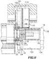
- Figure 7 shows a device 74 for roll forming the ends of a pipe element and imparting a shape to its sidewalk
- Device 74 comprises a support frame 76 on which is mounted a first or inner roller 78, and a second or outer roller 80.
- Inner roller 78 is mounted for rotation about an axis 82 and is adapted to engage and support an inner surface of a pipe element during the cold working process disclosed herein.
- Means 84 for rotating the inner roller are provided with device 74.
- Such means may include, for example an electric motor, or a hydraulic motor operated by a pump.
- Outer roller 80 is mounted on a yoke 86 and is free to rotate about an axis 88 which is substantially parallel to the axis of rotation 82 of the inner roller 78.
- Yoke 86 allows the outer roller 80 to move toward and away from the inner roller 78 so that it may engage an outer surface of the pipe element during roll forming.
- Means 90 are provided to move the outer roller 80 on yoke 86, and such means may comprise, for example, a hydraulic actuator or a jackscrew.
- Inner roller 78 is formed of a plurality of segments having different outer diameters which cooperate with various segments comprising the outer roller 80 (which are also distinguishable from one another by their respective outer diameters) to impart a desired shape to the pipe element sidewall as described herein.
- Inner roller 78 is comprised of a first segment 94 having an outer diameter 94a, a second segment 96 positioned contiguous with the first segment and having an outer diameter 96a smaller than outer diameter 94a, a third segment 98 positioned contiguous with the second segment and having an outer diameter 98a larger than outer diameter 96a, a eighth segment 100 positioned contiguous with the third segment and having an outer diameter 100a smaller than outer diameter 96a, and a ninth segment 102 positioned contiguous with the eighth segment (100) and having an outer diameter 102a approximately equal to outer diameter 96a.
- outer roller 80 is comprised of a fourth segment 104 having an outer diameter 104a, a fifth segment 106 positioned contiguous with the fourth segment 104 and having an outer diameter 106a greater than outer diameter 104a, a sixth segment 108 positioned contiguous with the fifth segment 106 and having outer diameter 108a less than outer diameter 106a, and a seventh segment 110 positioned contiguous with the sixth segment 108 and having an outer diameter 110a approximately equal to outer diameter 106a.
- the rollers are aligned so as to cooperate with one another and impart the desired sidewall shape.
- the segment 94 on the inner roller 78 is aligned with segment 104 on the outer roller 80; segment 96 on the inner roller is aligned with segment 106 on the outer roller; segment 98 on the inner roller is aligned with segment 108 on the outer roller, and segments 100 and 102 on the inner roller are aligned with segment 110 on the outer roller.
- Annular surfaces on each of the rollers also cooperate in pairs with one another to impart the desired shape to the pipe element sidewall.
- an annular surface 112 positioned on inner roller 78 between segments 94 and 96 cooperates with an annular surface 114 positioned on outer roller 80 between segments 104 and 106 to form the first side surface 36 of the groove 24.
- Annular surface 114 can be considered part of segment 106 and, in this example, is oriented substantially perpendicularly to the axis of rotation 88 of the outer roller 80.
- annular surface 116 positioned on outer roller 80 between segments 106 and 108 cooperates with an annular surface 118 positioned on inner roller 78 between segments 96 and 98 to form the second side surface 38 of groove 24.
- Annular surface 116 may also be considered part of segment 106, and is angularly oriented with respect to axis 88. Orientation angles 120 may range from about 40° to about 70° or from about 45° to about 65° or may be at about 55°.
- the annular surfaces on the inner roller 78 will have substantially the same orientation as the annular surface on the outer roller 80 with which they cooperate, however, other configurations are of course feasible.
- a flange 122 which, in this example, extends radially outwardly from the inner roller 78 and engages a groove 124 in the outer roller 80 when the outer roller 80 is moved towards the inner roller 78 to compress the pipe element between them during cold working.
- FIGs 9-11 illustrate an example method of roll forming a pipe element 10 to impart the sidewall shape as shown in Figure 1 .
- pipe element 10 is supported on inner roller 78 with its inner surface 126 contacting at least two of the segments 94, 98 and 102 at respective contact points 128, 129 and 130.
- contact may be at 128, 129 and 130 or at any two of the three.
- contact will be at 128 and may be at 129 and 130.
- Outer roller 80 is moved toward the inner roller 78 and contacts the outer surface 132 of pipe element 10 with segment 106.
- Flange 122 on inner roller 78 acts as a stop to properly position the pipe element axially on the rollers.
- both the inner and outer rollers 78 and 80 are in contact with the pipe element 10 the inner roller is rotated about axis 82 by rotating means 84.
- This causes pipe element 10 to rotate in the same direction as the inner roller 78, and the outer roller 80 to rotate in the opposite direction about its axis 88.
- it is advantageous to rotate the inner roller and move the outer roller toward it it is understood that other combinations of rotating and moving the rollers are also feasible.
- outer roller 80 is moved toward the inner roller 78 to compress the pipe element between the rollers while the rollers are rotating.
- the pipe element sidewall 134 is thereby deformed through contact between the pipe element inner surface 126 and segments 94 and 98 of inner roller 78, and segments 106 and 110 of outer roller 80. This action begins to form the shoulder 22, the groove 24 and bead 26 in the sidewall 134.
- the rollers and pipe element continue to rotate, and, as shown in Figure 11 , the outer roller 80 is moved further towards inner roller 78 to further compress the sidewall 134.
- Sidewall 134 is compressed between segments 94 and 104 to form the shoulder 22, the compressive force between the segments thinning the sidewall over the region of the shoulder 22 and enlarging its diameter to a desired final outer diameter 30 as shown in Figure 1 .
- Sidewall 134 is also compressed between segments 96 and 106 to establish the final dimensions of the groove floor 42, including its outer diameter 44 shown in Figure 1 .
- the sidewall 134 is also compressed between segments 96 and 106 to establish the inner diameter 17 of the portion of the pipe element 10 comprising the groove 24 to be approximately equal to the pipe inner diameter 19 (which is not compressed between the rollers) as shown in Figure 1 .
- the sidewall 134 is compressed between annular surface 116 and the annular surface 118 to form the second side surface 38 of the groove 24 (the first side surface having been formed by cooperation between annular surfaces 112 and 114).
- Segment 110 also contacts the outer surface 132 of the pipe element 10 to assist in forming the bead 26.
Priority Applications (1)
| Application Number | Priority Date | Filing Date | Title |
|---|---|---|---|
| PL15176201T PL2959986T3 (pl) | 2010-12-02 | 2011-11-30 | Sposób i aparatura do wytwarzania elementu rurowego mającego wzmocnienie, żłobienie i zgrubienie |
Applications Claiming Priority (4)
| Application Number | Priority Date | Filing Date | Title |
|---|---|---|---|
| US41896710P | 2010-12-02 | 2010-12-02 | |
| US201161530771P | 2011-09-02 | 2011-09-02 | |
| EP11844300.1A EP2643625B1 (en) | 2010-12-02 | 2011-11-30 | Pipe element having shoulder, groove and bead and methods and apparatus for manufacture thereof |
| PCT/US2011/062563 WO2012075095A2 (en) | 2010-12-02 | 2011-11-30 | Pipe element having shoulder, groove and bead and methods and apparatus for manufacture thereof |
Related Parent Applications (2)
| Application Number | Title | Priority Date | Filing Date |
|---|---|---|---|
| EP11844300.1A Division EP2643625B1 (en) | 2010-12-02 | 2011-11-30 | Pipe element having shoulder, groove and bead and methods and apparatus for manufacture thereof |
| EP11844300.1A Division-Into EP2643625B1 (en) | 2010-12-02 | 2011-11-30 | Pipe element having shoulder, groove and bead and methods and apparatus for manufacture thereof |
Publications (2)
| Publication Number | Publication Date |
|---|---|
| EP2959986A1 EP2959986A1 (en) | 2015-12-30 |
| EP2959986B1 true EP2959986B1 (en) | 2018-12-19 |
Family
ID=46161503
Family Applications (4)
| Application Number | Title | Priority Date | Filing Date |
|---|---|---|---|
| EP15176201.0A Not-in-force EP2959986B1 (en) | 2010-12-02 | 2011-11-30 | Method and apparatus for manufacturing a pipe element having shoulder, groove and bead |
| EP11844300.1A Active EP2643625B1 (en) | 2010-12-02 | 2011-11-30 | Pipe element having shoulder, groove and bead and methods and apparatus for manufacture thereof |
| EP14158515.8A Active EP2759354B1 (en) | 2010-12-02 | 2011-11-30 | Method and apparatus for manufacturing a pipe element having shoulder, groove and bead |
| EP20140158108 Withdrawn EP2745950A1 (en) | 2010-12-02 | 2011-11-30 | Method and apparatus for manufacturing a pipe element having shoulder, groove and bead |
Family Applications After (3)
| Application Number | Title | Priority Date | Filing Date |
|---|---|---|---|
| EP11844300.1A Active EP2643625B1 (en) | 2010-12-02 | 2011-11-30 | Pipe element having shoulder, groove and bead and methods and apparatus for manufacture thereof |
| EP14158515.8A Active EP2759354B1 (en) | 2010-12-02 | 2011-11-30 | Method and apparatus for manufacturing a pipe element having shoulder, groove and bead |
| EP20140158108 Withdrawn EP2745950A1 (en) | 2010-12-02 | 2011-11-30 | Method and apparatus for manufacturing a pipe element having shoulder, groove and bead |
Country Status (16)
| Country | Link |
|---|---|
| US (4) | US8777277B2 (es) |
| EP (4) | EP2959986B1 (es) |
| JP (2) | JP5667700B2 (es) |
| KR (4) | KR101895518B1 (es) |
| AU (2) | AU2011336680B9 (es) |
| BR (2) | BR112013011398B1 (es) |
| CA (3) | CA3090856C (es) |
| DK (1) | DK2959986T3 (es) |
| ES (3) | ES2559026T3 (es) |
| HK (1) | HK1212290A1 (es) |
| IL (3) | IL225253A (es) |
| MX (4) | MX366355B (es) |
| PL (1) | PL2959986T3 (es) |
| SG (2) | SG189897A1 (es) |
| TW (2) | TWI558479B (es) |
| WO (1) | WO2012075095A2 (es) |
Families Citing this family (48)
| Publication number | Priority date | Publication date | Assignee | Title |
|---|---|---|---|---|
| US7086131B2 (en) * | 2004-05-14 | 2006-08-08 | Victaulic Company | Deformable mechanical pipe coupling |
| US8282136B2 (en) | 2008-06-30 | 2012-10-09 | Mueller International, Llc | Slip on groove coupling with multiple sealing gasket |
| US8621741B2 (en) * | 2009-11-30 | 2014-01-07 | Howard Hagiya | 4-way compression grooved coupling |
| ES2548775T3 (es) * | 2011-09-02 | 2015-10-20 | Victaulic Company | Procedimiento y dispositivo para moldear por centrifugación |
| DE102011116768A1 (de) * | 2011-10-22 | 2013-04-25 | Norma Germany Gmbh | Profilschelle mit Dichtelement |
| USD696751S1 (en) | 2011-10-27 | 2013-12-31 | Mueller International, Llc | Slip-on gasket |
| USD680629S1 (en) | 2011-11-21 | 2013-04-23 | Mueller International, Llc | Slip-on coupling segment |
| USD680630S1 (en) | 2011-11-21 | 2013-04-23 | Mueller International, Llc | Slip-on coupling assembly |
| US9194516B2 (en) | 2012-01-20 | 2015-11-24 | Mueller International, Llc | Slip-on coupling |
| US9039046B2 (en) | 2012-01-20 | 2015-05-26 | Mueller International, Llc | Coupling with tongue and groove |
| US9500307B2 (en) | 2012-01-20 | 2016-11-22 | Mueller International, Llc | Slip-on coupling gasket |
| US9534715B2 (en) | 2012-01-20 | 2017-01-03 | Mueller International, Llc | Coupling gasket with multiple sealing surfaces |
| DE102012008970B3 (de) * | 2012-05-03 | 2013-06-27 | Joimax Gmbh | Chirurgische Werkzeugeinrichtung |
| US9199295B2 (en) * | 2012-09-10 | 2015-12-01 | The Boeing Company | Roller swage method and apparatus |
| US9168585B2 (en) | 2012-11-02 | 2015-10-27 | Mueller International, Llc | Coupling with extending parting line |
| US8776835B2 (en) * | 2012-12-05 | 2014-07-15 | Hamilton Sundstrand Corporation | Fluid duct with improved connecting bead |
| MY175943A (en) * | 2013-01-17 | 2020-07-16 | Univ Malaya | A method of producing a unitary pipe having a combination of square and circular cross sections |
| US9333548B2 (en) | 2013-08-12 | 2016-05-10 | Victaulic Company | Method and device for forming grooves in pipe elements |
| JP5727663B1 (ja) * | 2013-11-18 | 2015-06-03 | 日新製鋼株式会社 | 流体送給管の継手部の転造加工方法および流体送給管 |
| USD731033S1 (en) * | 2014-02-13 | 2015-06-02 | Neoperl Gmbh | Flexible hose with hose connection or hose fittings |
| US10189070B2 (en) * | 2014-08-29 | 2019-01-29 | Victaulic Company | Roller for roll forming |
| US10369609B2 (en) * | 2014-08-29 | 2019-08-06 | Victaulic Company | Roller with compound angle flange |
| US10245631B2 (en) * | 2014-10-13 | 2019-04-02 | Victaulic Company | Roller set and pipe elements |
| PT3015751T (pt) * | 2014-10-31 | 2018-01-09 | Apex Gold International Ltd | Peça acessória de ajustamento para conexão a um elemento tubular, conexão de tubagem e um método para a conexão de uma peça acessória de ajustamento a um elemento tubular |
| CN105107971B (zh) * | 2015-09-30 | 2017-04-19 | 甘志宏 | 一种金属管道连接用滚压连接装置及其滚压方法 |
| CN105215118B (zh) * | 2015-11-03 | 2017-06-06 | 成都中电锦江信息产业有限公司 | 一种滚槽机 |
| KR101654238B1 (ko) | 2015-11-23 | 2016-09-06 | 정우금속공업 주식회사 | 배관 연결장치 및 이의 제조방법 |
| CA3009356C (en) | 2015-12-28 | 2020-07-21 | Victaulic Company | Adapter coupling |
| ES2951087T3 (es) * | 2016-01-26 | 2023-10-17 | Victaulic Co Of America | Combinación que comprende un acoplamiento y un elemento de tubería con ranura de cuña |
| US10859190B2 (en) | 2016-05-16 | 2020-12-08 | Victaulic Company | Sprung coupling |
| USD816191S1 (en) * | 2016-06-13 | 2018-04-24 | 5132887 Manitoba Ltd. | Plumbing fitting |
| DE102016124487A1 (de) * | 2016-12-15 | 2018-06-21 | Mv Pipe Technologies Gmbh | Vorrichtung und Verfahren zum Erzeugen einer umlaufenden Nut in einem Endabschnitt eines Metallrohres |
| SG10201913214UA (en) * | 2017-01-19 | 2020-03-30 | Victaulic Co Of America | Direct coupling compatible sprinkler |
| US11035505B2 (en) | 2017-02-06 | 2021-06-15 | North American Pipe Corporation | System, method and apparatus for in-line removable pipe assembly |
| US11268638B2 (en) | 2017-07-28 | 2022-03-08 | ASC Engineered Solutions, LLC | Pre-assembled coupling assemblies with pipe fitting |
| US11209107B2 (en) | 2017-07-28 | 2021-12-28 | ASC Engineered Solutions, LLC | Pre-assembled coupling assembly with cap |
| USD845702S1 (en) * | 2017-11-29 | 2019-04-16 | Tyrone Wilson, SR. | Drinking straw regulator |
| USD865919S1 (en) | 2018-01-08 | 2019-11-05 | Tyco Fire Products Lp | Pipe coupling |
| JP2019132425A (ja) * | 2018-01-29 | 2019-08-08 | 日本ヴィクトリック株式会社 | 配管継手構造 |
| CN108772481B (zh) * | 2018-06-28 | 2023-11-10 | 成都飞机工业(集团)有限责任公司 | 一种双扩口导管滚波成形方法 |
| KR102102038B1 (ko) | 2018-06-29 | 2020-04-17 | 파이발텍 주식회사 | 그루브 형성장치 |
| DE102019133414A1 (de) | 2018-12-07 | 2020-06-10 | Minimax Viking Research & Development Gmbh | Verfahren und System zur Modellierung eines Rohrnetzwerks |
| KR101976100B1 (ko) * | 2019-03-28 | 2019-05-09 | (주)한서티앤티 | 밴딩 파이프 가공용 펀칭장치 |
| US10711929B1 (en) * | 2019-06-29 | 2020-07-14 | Shanghai Vision Mechanical Joint Co., Ltd. | Pipe element coupler and coupling method thereof |
| US11781683B2 (en) | 2019-11-15 | 2023-10-10 | Victaulic Company | Shrouded coupling |
| KR102168474B1 (ko) * | 2020-05-19 | 2020-10-21 | 부성테크(주) | 서스펜션 미들튜브 제조 시스템 |
| DE102021202883A1 (de) * | 2021-03-24 | 2022-09-29 | Glatt Gesellschaft Mit Beschränkter Haftung | System mit einer Vorrichtung zur Herstellung einer Rohrleitungseinheit und Verfahren zur Herstellung einer Rohrleitungseinheit |
| CN114589467B (zh) * | 2022-03-29 | 2023-04-28 | 成都光明派特贵金属有限公司 | 贵金属多级变径通道及其制作方法 |
Family Cites Families (133)
| Publication number | Priority date | Publication date | Assignee | Title |
|---|---|---|---|---|
| US433271A (en) | 1890-07-29 | Machine for expanding can-covers | ||
| US514588A (en) | 1894-02-13 | Flue expander and beader | ||
| US411130A (en) * | 1889-09-17 | Territory | ||
| US40967A (en) | 1863-12-15 | Improvement in tools for fastening boiler-tubes | ||
| US818843A (en) | 1905-12-16 | 1906-04-24 | Washington Mccormick | Tube expanding and beading tool. |
| US856896A (en) | 1906-10-19 | 1907-06-11 | Washington Mccormick | Tube expanding and beading tool. |
| US1472047A (en) | 1922-05-13 | 1923-10-30 | Crane Co | Method of lapping metal pipes |
| US1582525A (en) | 1922-12-18 | 1926-04-27 | Adolph Mueller | Machine for spinning, trimming, or flanging thin metal tubes |
| US1967031A (en) | 1930-11-22 | 1934-07-17 | Chrysler Corp | Method of coating articles |
| US2355852A (en) | 1943-06-08 | 1944-08-15 | Frank F Fisher | Tube expanding tool |
| US2777715A (en) * | 1952-06-24 | 1957-01-15 | Walter O Beyer | Flange coupling with sealing means responsive to internal or external pressure |
| US2821415A (en) * | 1953-04-09 | 1958-01-28 | Race & Race Inc | Grooved and internally reinforced pipe end |
| US2933124A (en) | 1955-01-24 | 1960-04-19 | Kronprinz Ag | Machines for the formation of wheel rims and the like |
| US3029667A (en) * | 1955-08-31 | 1962-04-17 | Lodge & Shipley Co | Metal working |
| US3015502A (en) * | 1957-11-29 | 1962-01-02 | Victaulic Co Of America | Grooved tubing for connection with sleeve type coupling |
| US3122830A (en) | 1959-06-08 | 1964-03-03 | Lockheed Aircraft Corp | Method for forming an integral flange on a metal tube |
| US3290914A (en) | 1963-08-28 | 1966-12-13 | Vaill Engineering Company | Method and apparatus for forming cylindrical shapes |
| US3311971A (en) | 1964-01-16 | 1967-04-04 | Nooter Corp | Vessel lining method |
| US3403931A (en) * | 1964-08-11 | 1968-10-01 | Gray Tool Co | Clamp |
| US3364709A (en) | 1965-02-02 | 1968-01-23 | Vaill Engineering Company | Machine tool for fabricating tubular members |
| US3382693A (en) | 1965-03-02 | 1968-05-14 | Vni Kt I Podshipnikovoi Promy | Ring rolling tool |
| US3381353A (en) * | 1965-08-04 | 1968-05-07 | Lemmerz Werke Gmbh | Method of making tire rim |
| US3541826A (en) * | 1968-02-19 | 1970-11-24 | Certain Teed Prod Corp | Roll grooving and swaging device |
| US3648500A (en) | 1969-08-22 | 1972-03-14 | Torrington Co | Method and apparatus for forming cylindrical shapes |
| GB1344066A (en) | 1970-08-04 | 1974-01-16 | Secr Defence | Metal working |
| US3680341A (en) | 1970-12-30 | 1972-08-01 | Flaturn Inc | Method and apparatus for reconditioning a drum of a reproducing machine |
| US3724878A (en) * | 1971-03-24 | 1973-04-03 | J Ford | Flexible connector |
| SU445496A1 (ru) | 1972-05-10 | 1974-10-05 | Предприятие П/Я Р-6331 | Устройство дл раскатки труб |
| US3787945A (en) | 1973-05-14 | 1974-01-29 | Gen Motors Corp | Method of fabricating an expanded tube connection |
| US3906771A (en) | 1974-07-17 | 1975-09-23 | Dresser Ind | Expander for random trim tubing |
| US4311248A (en) | 1974-11-04 | 1982-01-19 | Construction Forms, Inc. | High pressure coupling apparatus |
| US3967837A (en) | 1974-11-04 | 1976-07-06 | Construction Forms, Inc. | High pressure coupling apparatus |
| US3995466A (en) * | 1975-09-19 | 1976-12-07 | Victaulic Company Of America | Machine for roll grooving of pipe |
| JPS52101748U (es) * | 1976-01-30 | 1977-08-02 | ||
| GB1578142A (en) | 1976-04-22 | 1980-11-05 | Metal Box Co Ltd | Expanding the moughs of hollow articles |
| JPS5329269A (en) * | 1976-08-31 | 1978-03-18 | Fuji Machine Mfg | Method and device for spinning forming of bellow pipe |
| JPS52101748A (en) | 1976-11-04 | 1977-08-26 | Hitachi Heating Appliance Co Ltd | Uniformly heating apparatus of electronic cooker |
| US4091648A (en) * | 1977-04-06 | 1978-05-30 | Zap-Lok Systems International | Pipe grooving systems |
| US4114414A (en) * | 1977-04-29 | 1978-09-19 | E.G. Sprinkler Corporation | Backup roll for thin walled pipe grooving device |
| US4134286A (en) | 1977-09-13 | 1979-01-16 | Dresser Industries, Inc. | Method and apparatus for expanding tubes |
| US4143535A (en) | 1978-02-21 | 1979-03-13 | Automatic Sprinkler Limited | Pipe end shaper |
| JPS5536071A (en) | 1978-09-07 | 1980-03-13 | Fuji Kikai Seizo Kk | Pattern molding machine to circumferential surface of vessel |
| SU730420A1 (ru) | 1978-09-22 | 1980-04-30 | Всесоюзный научно-исследовательский и проектно-технологический институт угольного машиностроения | Устройство дл развальцовки трубчатых заготовок |
| FR2475949A1 (fr) | 1980-02-15 | 1981-08-21 | Vallourec | Procede de dudgeonnage, dudgeon susceptible d'etre utilise pour la mise en oeuvre de ce procede, et assemblage obtenu a l'aide de ce procede |
| US4319472A (en) | 1980-03-07 | 1982-03-16 | Carrier Corporation | Tube end expander and method of operating the same |
| JPS5865089U (ja) * | 1981-10-24 | 1983-05-02 | 高木 賢次郎 | 装飾兼広告装置 |
| US4527818A (en) * | 1981-02-17 | 1985-07-09 | Texaco Inc. | Coupling for pipe or tubing |
| JPS6031576U (ja) * | 1981-09-30 | 1985-03-04 | カルソニックカンセイ株式会社 | 空気調和装置のパイプ連結構造 |
| US4522433A (en) | 1982-05-14 | 1985-06-11 | Stanley Aviation Corporation | Spherical seat flexible O-ring coupling |
| GB2128522B (en) | 1982-09-29 | 1986-02-26 | Carrier Corp | A tube expanding and grooving tool and method |
| JPS6030891U (ja) * | 1983-08-09 | 1985-03-02 | 株式会社 吉川製作所 | サイドプル式キャリパ−ブレ−キのブレ−キシュ−構造 |
| JPS6133719A (ja) | 1984-07-26 | 1986-02-17 | Daido Metal Kogyo Kk | つば付ブシユの製造方法およびその装置 |
| US4706355A (en) | 1984-12-11 | 1987-11-17 | Q-Dot Corporation | Method of making an internally grooved and expanded tubular heat exchanger apparatus |
| JPH067968B2 (ja) | 1985-02-13 | 1994-02-02 | 株式会社日立製作所 | パイプの端部加工装置 |
| DE3662812D1 (en) * | 1985-05-11 | 1989-05-18 | Niigata Engineering Co Ltd | Quick release coupling device |
| US4615198A (en) | 1985-06-26 | 1986-10-07 | Westinghouse Electric Corp. | Apparatus and method for reforming and rolling tube ends |
| JPS623590A (ja) | 1985-06-28 | 1987-01-09 | Matsushita Electric Ind Co Ltd | カラ−映像信号再生装置 |
| JPH0212382Y2 (es) * | 1985-11-21 | 1990-04-06 | ||
| US4716752A (en) | 1986-05-13 | 1988-01-05 | Dresser Industries, Inc. | Tube expanding and flaring tool |
| JPS63149038A (ja) | 1986-12-15 | 1988-06-21 | Nippon Steel Corp | 外アツプセツト・プレスによる鋼管端部の加工方法 |
| JPH0212382A (ja) | 1988-06-29 | 1990-01-17 | Nec Corp | エアブラシ描画方式 |
| JPH0318876A (ja) | 1989-06-16 | 1991-01-28 | Nec Corp | 電子写真装置の帯電器 |
| US4942751A (en) | 1989-10-13 | 1990-07-24 | R. Gale Rhodes, Jr. | Process and apparatus for forming internally enhanced tubing |
| IT1236712B (it) | 1989-11-15 | 1993-03-26 | Procedimento e apparecchiatura per la produzione di tubi in lega leggera a diametro maggiorato a partire da tubi a diametro inferiore. | |
| US5080400A (en) * | 1990-04-30 | 1992-01-14 | Abb Vetro Gray Inc. | Double lobe tubular connector clamp |
| RU1787625C (ru) | 1990-07-09 | 1993-01-15 | Н.М. Бурштейн | Способ раздачи конца трубы |
| US5531370A (en) | 1990-08-14 | 1996-07-02 | Rohrberg; Roderick G. | High-precision sizing, cutting and welding tool system for specialty aerospace alloys |
| DE4037306C1 (es) | 1990-11-23 | 1991-11-28 | Rasmussen Gmbh, 6457 Maintal, De | |
| JPH04339522A (ja) * | 1991-05-15 | 1992-11-26 | Matsushita Electric Works Ltd | 金属パイプの端部の縮径加工方法 |
| US5184495A (en) | 1991-12-03 | 1993-02-09 | Prideco, Inc. | Method of internally and externally upsetting the end of a metal tube |
| US5327756A (en) | 1991-12-31 | 1994-07-12 | Fox Francis J | Method and apparatus for forming spiral grooves internally in metal tubing |
| US5279143A (en) * | 1993-01-15 | 1994-01-18 | Victaulic Company Of America | Self-tracking roll for grooving thin walled pipe |
| US5450738A (en) | 1993-08-31 | 1995-09-19 | Grinnell Corporation | Method and apparatus for forming piping element connections having multiple outward steps |
| JP2960964B2 (ja) | 1993-11-29 | 1999-10-12 | プロプライアタリー・テクノロジー・インコーポレーテッド | 導管カップリング |
| JP3018876B2 (ja) | 1993-12-03 | 2000-03-13 | 東洋インキ製造株式会社 | 電子写真用現像剤 |
| JP3164272B2 (ja) | 1994-02-02 | 2001-05-08 | ディン カーン | ヒートパイプの製造方法およびその製造に用いる加工具 |
| DE4437395A1 (de) | 1994-10-19 | 1996-05-02 | Werdau Fahrzeugwerk | Verfahren zum Anstauchen von Rohrenden und Vorrichtung zur Durchführung des Verfahrens |
| JP3018876U (ja) * | 1995-05-31 | 1995-11-28 | 株式会社東洋アソシエイツ | 管の取り付け具 |
| JPH0953772A (ja) | 1995-08-12 | 1997-02-25 | Shizusei Kogyo Kk | ステンレス鋼管の接続構造及び接続端部の成形装置 |
| JPH09152068A (ja) * | 1995-12-01 | 1997-06-10 | Benkan Corp | 薄肉ステンレス鋼管と管継手との接続機構 |
| US5890287A (en) | 1996-01-10 | 1999-04-06 | Usui Kokusai Sangyo Kaisha Limited | Connection structure and process for connecting eye joints and slender metal pipes |
| JP3744044B2 (ja) * | 1996-01-22 | 2006-02-08 | 株式会社デンソー | パイプ多段ひも出し加工装置 |
| FR2766253B1 (fr) * | 1997-07-21 | 1999-10-08 | Caillau Ets | Dispositif de connexion entre un tube et un tuyau souple procede pour fabriquer un tel dispositif |
| DE29721760U1 (de) | 1997-12-10 | 1998-01-29 | Franz Viegener Ii Gmbh & Co Kg | Unlösbare Preßverbindung zwischen einem Fitting und einem Metallrohrende |
| US5904063A (en) | 1998-01-16 | 1999-05-18 | Owens; Carl H. | Tube beading apparatus |
| NO310226B1 (no) | 1998-02-03 | 2001-06-11 | Kongsberg Automotive Asa | Fremgangsmåte og verktöy for tildannelse av et forstörret endeparti av en stang |
| US6032502A (en) | 1998-08-31 | 2000-03-07 | American National Can Co. | Apparatus and method for necking containers |
| FR2786417B1 (fr) * | 1998-11-27 | 2001-01-19 | Ems Societe | Procede et dispositif de formage a froid d'un bourrelet peripherique dans l'extremite d'un tube notamment metallique |
| US6233991B1 (en) | 1999-01-26 | 2001-05-22 | Bryant Products, Inc. | Apparatus and method for spin forming a tube |
| CA2483113C (en) | 1999-02-24 | 2007-10-02 | Copperweld Canada Inc. | Process for cold forming tube ends |
| US6196039B1 (en) * | 1999-03-25 | 2001-03-06 | Anvil International, Inc. | Groove rolling of piping elements |
| US6390124B1 (en) * | 1999-08-06 | 2002-05-21 | Futaba Industrial Co. Ltd. | Fuel inlet and manufacturing method thereof |
| FR2801522B1 (fr) * | 1999-11-30 | 2002-02-01 | Parker Hannifin Sa | Procede de deformation d'un tube a proximite de l'une de ses extremites et outil mis en oeuvre dans ce procede |
| DE10031989B4 (de) | 2000-06-30 | 2007-08-16 | Witzig & Frank Gmbh | Verfahren und Vorrichtung zur Herstellung von Pressfittings aus Stahl, insbesondere Edelstahl |
| NL1015773C2 (nl) | 2000-07-21 | 2002-01-22 | Johan Massue | Werkwijze en inrichting voor het vervormen van een hol werkstuk. |
| NL1016348C2 (nl) | 2000-07-21 | 2002-01-22 | Johan Massue | Werkwijze en forceermachine voor het vervormen van een hol werkstuk. |
| CN1447724A (zh) | 2000-08-16 | 2003-10-08 | 帕克-汉尼芬有限公司 | 使工件端部成形的装置 |
| DE60104137T2 (de) | 2000-10-05 | 2005-08-25 | Tesma International Inc., Concord | Kaltverformung von antriebskeilnaben |
| AT4835U1 (de) * | 2000-11-13 | 2001-12-27 | Tesma Motoren Getriebetechnik | Treibstoffbehälter mit einem rohr |
| US7415765B2 (en) | 2002-03-27 | 2008-08-26 | Ohtsuka Co., Ltd. | Flange coupling and manufacturing method for the same |
| ES2194612B1 (es) * | 2002-05-08 | 2005-03-01 | Dinak, S.A. | Sistema de acoplamiento estanco para chimeneas y conductos modulares prefabricados. |
| JP3949513B2 (ja) | 2002-05-27 | 2007-07-25 | 本田技研工業株式会社 | 超塑性加工用金型 |
| JP3504653B1 (ja) | 2002-08-28 | 2004-03-08 | 清 小川 | 鋼管複合加工設備と鋼管加工方法 |
| ITMI20030010A1 (it) | 2003-01-08 | 2004-07-09 | Antonio Romanelli | Raccordo a compressione per tubi. |
| JP4346951B2 (ja) * | 2003-05-08 | 2009-10-21 | 株式会社ベステックスキョーエイ | フューエルインレットの製造方法 |
| US6918278B2 (en) * | 2003-06-20 | 2005-07-19 | Victaulic Company Of America | Pipe preparation tool adaptable for different diameter pipes |
| JP3823952B2 (ja) | 2003-07-04 | 2006-09-20 | 東洋製罐株式会社 | エンボス加工缶体の製造方法 |
| DE10331061B4 (de) * | 2003-07-09 | 2005-05-19 | Technische Universität Dresden | Ringförmige Verbundwerkstücke und Kaltwalzverfahren zu ihrer Fertigung |
| JP3839803B2 (ja) * | 2003-08-08 | 2006-11-01 | 5Zigenインターナショナル株式会社 | 自動車用マフラーの出口位置決め調整装置 |
| DE10350682A1 (de) * | 2003-10-30 | 2005-06-02 | Daimlerchrysler Ag | Rohrleitungsverbindung |
| US7114358B2 (en) | 2004-01-06 | 2006-10-03 | Arrow Fabricated Tubing, Ltd. | Tube expanding apparatus |
| DE102004003693B3 (de) | 2004-01-24 | 2004-12-09 | Rasmussen Gmbh | Steckkupplung zum Anschließen einer Fluidleitung an einem Rohr |
| US8267432B2 (en) * | 2004-03-26 | 2012-09-18 | Victaulic Company | Coupling having angularly oriented key surfaces |
| CA2561272C (en) * | 2004-03-26 | 2014-02-18 | Victaulic Company | Pipe coupling having keys with camming surfaces |
| TW200602577A (en) * | 2004-04-22 | 2006-01-16 | Swagelok Co | Fitting for tube and pipe |
| US7086131B2 (en) | 2004-05-14 | 2006-08-08 | Victaulic Company | Deformable mechanical pipe coupling |
| US7712796B2 (en) * | 2004-05-14 | 2010-05-11 | Victaulic Company | Deformable mechanical pipe coupling |
| US7316142B2 (en) | 2004-05-21 | 2008-01-08 | Lancaster Paul B | Metal spin forming head |
| US7225660B1 (en) | 2005-05-13 | 2007-06-05 | Kw Industries, Inc. | Apparatus and method for expanding a tube diameter and a pole formed thereby |
| JP4851815B2 (ja) | 2006-03-01 | 2012-01-11 | 株式会社スギノマシン | 拡管装置 |
| DE102006038989B3 (de) | 2006-08-21 | 2007-12-13 | Esser-Werke Gmbh & Co. Kg | Förderrohr für den Feststofftransport |
| DE102007002228A1 (de) * | 2007-01-10 | 2008-07-31 | Benteler Automobiltechnik Gmbh | Verfahren und Vorrichtung zur Herstellung von innenprofilierten Rohren |
| US8246709B2 (en) * | 2007-04-20 | 2012-08-21 | Tehag Ag | Device and method for connecting housing sections of soot particle filters |
| US7950701B2 (en) | 2007-05-15 | 2011-05-31 | Victaulic Company | Pipe coupling having movable gripping bodies |
| CN201102044Y (zh) | 2007-09-04 | 2008-08-20 | 潘鑫钟 | 一种金属管端部的凸环成型工具 |
| US20090083962A1 (en) * | 2007-09-27 | 2009-04-02 | Langdon Incorporated | Flange-forming system for tube and related methods |
| US8033579B2 (en) * | 2007-10-05 | 2011-10-11 | Ckd Corporation | Fluid device connecting structure |
| US8079621B2 (en) | 2007-11-15 | 2011-12-20 | Lincoln Brass Works, Inc. | Reinforced bead tube design |
| JP5722046B2 (ja) * | 2008-01-30 | 2015-05-20 | ノーマ・ユー・エス・ホールディング・リミテッド・ライアビリティ・カンパニーNorma U. S. Holding Llc | ガスケット付中心リブを備えた単一ボルトバンドクランプおよびそれを用いるパイプ重ね継手 |
| JP2009222107A (ja) | 2008-03-14 | 2009-10-01 | Riken Corp | ハウジング形管継手 |
| EP2184525B1 (de) * | 2008-11-06 | 2011-10-19 | Eifeler Maschinenbau GmbH | Rohrverbindung mit einem Rohr und Verfahren zur Herstellung eines Verbindungsabschnitts einer Rohrverbindung |
| US7931310B2 (en) * | 2009-03-10 | 2011-04-26 | Western Oilfields Supply Co. | Pipe coupler |
| ES2548775T3 (es) * | 2011-09-02 | 2015-10-20 | Victaulic Company | Procedimiento y dispositivo para moldear por centrifugación |
-
2011
- 2011-11-30 DK DK15176201.0T patent/DK2959986T3/en active
- 2011-11-30 CA CA3090856A patent/CA3090856C/en active Active
- 2011-11-30 CA CA3003037A patent/CA3003037C/en active Active
- 2011-11-30 MX MX2015009635A patent/MX366355B/es unknown
- 2011-11-30 SG SG2013028212A patent/SG189897A1/en unknown
- 2011-11-30 EP EP15176201.0A patent/EP2959986B1/en not_active Not-in-force
- 2011-11-30 US US13/307,404 patent/US8777277B2/en active Active
- 2011-11-30 EP EP11844300.1A patent/EP2643625B1/en active Active
- 2011-11-30 MX MX2015009639A patent/MX364975B/es unknown
- 2011-11-30 ES ES14158515.8T patent/ES2559026T3/es active Active
- 2011-11-30 KR KR1020187010739A patent/KR101895518B1/ko active IP Right Grant
- 2011-11-30 AU AU2011336680A patent/AU2011336680B9/en active Active
- 2011-11-30 WO PCT/US2011/062563 patent/WO2012075095A2/en active Application Filing
- 2011-11-30 BR BR112013011398-7A patent/BR112013011398B1/pt active IP Right Grant
- 2011-11-30 ES ES11844300.1T patent/ES2653697T3/es active Active
- 2011-11-30 MX MX2013006221A patent/MX2013006221A/es active IP Right Grant
- 2011-11-30 CA CA2818980A patent/CA2818980C/en active Active
- 2011-11-30 BR BR122014029444-1A patent/BR122014029444B1/pt not_active IP Right Cessation
- 2011-11-30 EP EP14158515.8A patent/EP2759354B1/en active Active
- 2011-11-30 ES ES15176201T patent/ES2716128T3/es active Active
- 2011-11-30 JP JP2013533020A patent/JP5667700B2/ja active Active
- 2011-11-30 KR KR1020187010741A patent/KR101935907B1/ko active IP Right Grant
- 2011-11-30 SG SG10201501517UA patent/SG10201501517UA/en unknown
- 2011-11-30 KR KR1020187010740A patent/KR101935908B1/ko active IP Right Grant
- 2011-11-30 PL PL15176201T patent/PL2959986T3/pl unknown
- 2011-11-30 EP EP20140158108 patent/EP2745950A1/en not_active Withdrawn
- 2011-11-30 KR KR1020137011923A patent/KR101895517B1/ko active IP Right Grant
- 2011-12-02 TW TW103145342A patent/TWI558479B/zh not_active IP Right Cessation
- 2011-12-02 TW TW100144469A patent/TWI468611B/zh active
-
2013
- 2013-03-17 IL IL225253A patent/IL225253A/en active IP Right Grant
- 2013-05-31 MX MX2019005601A patent/MX2019005601A/es unknown
-
2014
- 2014-03-28 US US14/228,283 patent/US9333543B2/en active Active
- 2014-05-28 US US14/288,654 patent/US9010164B2/en active Active
- 2014-12-12 JP JP2014251611A patent/JP6021197B2/ja not_active Expired - Fee Related
-
2016
- 2016-01-12 HK HK16100263.2A patent/HK1212290A1/xx not_active IP Right Cessation
- 2016-01-14 AU AU2016200217A patent/AU2016200217B2/en active Active
- 2016-04-08 US US15/094,036 patent/US10161547B2/en active Active
- 2016-09-29 IL IL248134A patent/IL248134B/en active IP Right Grant
-
2017
- 2017-11-14 IL IL255651A patent/IL255651B/en active IP Right Grant
Non-Patent Citations (1)
| Title |
|---|
| None * |
Also Published As
Similar Documents
| Publication | Publication Date | Title |
|---|---|---|
| EP2959986B1 (en) | Method and apparatus for manufacturing a pipe element having shoulder, groove and bead | |
| US9038428B2 (en) | Spin forming method |
Legal Events
| Date | Code | Title | Description |
|---|---|---|---|
| PUAI | Public reference made under article 153(3) epc to a published international application that has entered the european phase |
Free format text: ORIGINAL CODE: 0009012 |
|
| AC | Divisional application: reference to earlier application |
Ref document number: 2643625 Country of ref document: EP Kind code of ref document: P |
|
| AK | Designated contracting states |
Kind code of ref document: A1 Designated state(s): AL AT BE BG CH CY CZ DE DK EE ES FI FR GB GR HR HU IE IS IT LI LT LU LV MC MK MT NL NO PL PT RO RS SE SI SK SM TR |
|
| 17P | Request for examination filed |
Effective date: 20160401 |
|
| RBV | Designated contracting states (corrected) |
Designated state(s): AL AT BE BG CH CY CZ DE DK EE ES FI FR GB GR HR HU IE IS IT LI LT LU LV MC MK MT NL NO PL PT RO RS SE SI SK SM TR |
|
| REG | Reference to a national code |
Ref country code: HK Ref legal event code: DE Ref document number: 1212290 Country of ref document: HK |
|
| STAA | Information on the status of an ep patent application or granted ep patent |
Free format text: STATUS: EXAMINATION IS IN PROGRESS |
|
| 17Q | First examination report despatched |
Effective date: 20171108 |
|
| GRAP | Despatch of communication of intention to grant a patent |
Free format text: ORIGINAL CODE: EPIDOSNIGR1 |
|
| STAA | Information on the status of an ep patent application or granted ep patent |
Free format text: STATUS: GRANT OF PATENT IS INTENDED |
|
| INTG | Intention to grant announced |
Effective date: 20180716 |
|
| GRAS | Grant fee paid |
Free format text: ORIGINAL CODE: EPIDOSNIGR3 |
|
| GRAA | (expected) grant |
Free format text: ORIGINAL CODE: 0009210 |
|
| STAA | Information on the status of an ep patent application or granted ep patent |
Free format text: STATUS: THE PATENT HAS BEEN GRANTED |
|
| AC | Divisional application: reference to earlier application |
Ref document number: 2643625 Country of ref document: EP Kind code of ref document: P |
|
| AK | Designated contracting states |
Kind code of ref document: B1 Designated state(s): AL AT BE BG CH CY CZ DE DK EE ES FI FR GB GR HR HU IE IS IT LI LT LU LV MC MK MT NL NO PL PT RO RS SE SI SK SM TR |
|
| REG | Reference to a national code |
Ref country code: GB Ref legal event code: FG4D |
|
| REG | Reference to a national code |
Ref country code: CH Ref legal event code: EP |
|
| REG | Reference to a national code |
Ref country code: IE Ref legal event code: FG4D |
|
| REG | Reference to a national code |
Ref country code: DE Ref legal event code: R096 Ref document number: 602011055033 Country of ref document: DE |
|
| REG | Reference to a national code |
Ref country code: AT Ref legal event code: REF Ref document number: 1078135 Country of ref document: AT Kind code of ref document: T Effective date: 20190115 |
|
| REG | Reference to a national code |
Ref country code: DK Ref legal event code: T3 Effective date: 20190212 |
|
| REG | Reference to a national code |
Ref country code: RO Ref legal event code: EPE |
|
| REG | Reference to a national code |
Ref country code: SE Ref legal event code: TRGR |
|
| REG | Reference to a national code |
Ref country code: NL Ref legal event code: FP |
|
| PG25 | Lapsed in a contracting state [announced via postgrant information from national office to epo] |
Ref country code: LT Free format text: LAPSE BECAUSE OF FAILURE TO SUBMIT A TRANSLATION OF THE DESCRIPTION OR TO PAY THE FEE WITHIN THE PRESCRIBED TIME-LIMIT Effective date: 20181219 Ref country code: BG Free format text: LAPSE BECAUSE OF FAILURE TO SUBMIT A TRANSLATION OF THE DESCRIPTION OR TO PAY THE FEE WITHIN THE PRESCRIBED TIME-LIMIT Effective date: 20190319 Ref country code: HR Free format text: LAPSE BECAUSE OF FAILURE TO SUBMIT A TRANSLATION OF THE DESCRIPTION OR TO PAY THE FEE WITHIN THE PRESCRIBED TIME-LIMIT Effective date: 20181219 Ref country code: LV Free format text: LAPSE BECAUSE OF FAILURE TO SUBMIT A TRANSLATION OF THE DESCRIPTION OR TO PAY THE FEE WITHIN THE PRESCRIBED TIME-LIMIT Effective date: 20181219 |
|
| REG | Reference to a national code |
Ref country code: LT Ref legal event code: MG4D |
|
| REG | Reference to a national code |
Ref country code: NO Ref legal event code: T2 Effective date: 20181219 |
|
| PG25 | Lapsed in a contracting state [announced via postgrant information from national office to epo] |
Ref country code: AL Free format text: LAPSE BECAUSE OF FAILURE TO SUBMIT A TRANSLATION OF THE DESCRIPTION OR TO PAY THE FEE WITHIN THE PRESCRIBED TIME-LIMIT Effective date: 20181219 Ref country code: RS Free format text: LAPSE BECAUSE OF FAILURE TO SUBMIT A TRANSLATION OF THE DESCRIPTION OR TO PAY THE FEE WITHIN THE PRESCRIBED TIME-LIMIT Effective date: 20181219 Ref country code: GR Free format text: LAPSE BECAUSE OF FAILURE TO SUBMIT A TRANSLATION OF THE DESCRIPTION OR TO PAY THE FEE WITHIN THE PRESCRIBED TIME-LIMIT Effective date: 20190320 |
|
| REG | Reference to a national code |
Ref country code: ES Ref legal event code: FG2A Ref document number: 2716128 Country of ref document: ES Kind code of ref document: T3 Effective date: 20190610 |
|
| PG25 | Lapsed in a contracting state [announced via postgrant information from national office to epo] |
Ref country code: PT Free format text: LAPSE BECAUSE OF FAILURE TO SUBMIT A TRANSLATION OF THE DESCRIPTION OR TO PAY THE FEE WITHIN THE PRESCRIBED TIME-LIMIT Effective date: 20190419 Ref country code: CZ Free format text: LAPSE BECAUSE OF FAILURE TO SUBMIT A TRANSLATION OF THE DESCRIPTION OR TO PAY THE FEE WITHIN THE PRESCRIBED TIME-LIMIT Effective date: 20181219 |
|
| PG25 | Lapsed in a contracting state [announced via postgrant information from national office to epo] |
Ref country code: IS Free format text: LAPSE BECAUSE OF FAILURE TO SUBMIT A TRANSLATION OF THE DESCRIPTION OR TO PAY THE FEE WITHIN THE PRESCRIBED TIME-LIMIT Effective date: 20190419 Ref country code: SK Free format text: LAPSE BECAUSE OF FAILURE TO SUBMIT A TRANSLATION OF THE DESCRIPTION OR TO PAY THE FEE WITHIN THE PRESCRIBED TIME-LIMIT Effective date: 20181219 Ref country code: EE Free format text: LAPSE BECAUSE OF FAILURE TO SUBMIT A TRANSLATION OF THE DESCRIPTION OR TO PAY THE FEE WITHIN THE PRESCRIBED TIME-LIMIT Effective date: 20181219 Ref country code: SM Free format text: LAPSE BECAUSE OF FAILURE TO SUBMIT A TRANSLATION OF THE DESCRIPTION OR TO PAY THE FEE WITHIN THE PRESCRIBED TIME-LIMIT Effective date: 20181219 |
|
| REG | Reference to a national code |
Ref country code: DE Ref legal event code: R097 Ref document number: 602011055033 Country of ref document: DE |
|
| PLBE | No opposition filed within time limit |
Free format text: ORIGINAL CODE: 0009261 |
|
| STAA | Information on the status of an ep patent application or granted ep patent |
Free format text: STATUS: NO OPPOSITION FILED WITHIN TIME LIMIT |
|
| 26N | No opposition filed |
Effective date: 20190920 |
|
| PGFP | Annual fee paid to national office [announced via postgrant information from national office to epo] |
Ref country code: PL Payment date: 20190920 Year of fee payment: 9 |
|
| REG | Reference to a national code |
Ref country code: DE Ref legal event code: R082 Ref document number: 602011055033 Country of ref document: DE Representative=s name: MEISSNER BOLTE PATENTANWAELTE RECHTSANWAELTE P, DE |
|
| PGFP | Annual fee paid to national office [announced via postgrant information from national office to epo] |
Ref country code: RO Payment date: 20191107 Year of fee payment: 9 Ref country code: SE Payment date: 20191108 Year of fee payment: 9 Ref country code: FI Payment date: 20191028 Year of fee payment: 9 Ref country code: IE Payment date: 20191029 Year of fee payment: 9 Ref country code: NO Payment date: 20191028 Year of fee payment: 9 |
|
| PG25 | Lapsed in a contracting state [announced via postgrant information from national office to epo] |
Ref country code: SI Free format text: LAPSE BECAUSE OF FAILURE TO SUBMIT A TRANSLATION OF THE DESCRIPTION OR TO PAY THE FEE WITHIN THE PRESCRIBED TIME-LIMIT Effective date: 20181219 |
|
| PGFP | Annual fee paid to national office [announced via postgrant information from national office to epo] |
Ref country code: DK Payment date: 20191028 Year of fee payment: 9 Ref country code: ES Payment date: 20191202 Year of fee payment: 9 Ref country code: IT Payment date: 20191113 Year of fee payment: 9 Ref country code: FR Payment date: 20191029 Year of fee payment: 9 Ref country code: BE Payment date: 20191021 Year of fee payment: 9 |
|
| PGFP | Annual fee paid to national office [announced via postgrant information from national office to epo] |
Ref country code: TR Payment date: 20191025 Year of fee payment: 9 Ref country code: AT Payment date: 20191028 Year of fee payment: 9 |
|
| PGFP | Annual fee paid to national office [announced via postgrant information from national office to epo] |
Ref country code: GB Payment date: 20191029 Year of fee payment: 9 |
|
| REG | Reference to a national code |
Ref country code: CH Ref legal event code: PL |
|
| REG | Reference to a national code |
Ref country code: NL Ref legal event code: MM Effective date: 20191201 |
|
| PG25 | Lapsed in a contracting state [announced via postgrant information from national office to epo] |
Ref country code: MC Free format text: LAPSE BECAUSE OF FAILURE TO SUBMIT A TRANSLATION OF THE DESCRIPTION OR TO PAY THE FEE WITHIN THE PRESCRIBED TIME-LIMIT Effective date: 20181219 Ref country code: LU Free format text: LAPSE BECAUSE OF NON-PAYMENT OF DUE FEES Effective date: 20191130 Ref country code: LI Free format text: LAPSE BECAUSE OF NON-PAYMENT OF DUE FEES Effective date: 20191130 Ref country code: CH Free format text: LAPSE BECAUSE OF NON-PAYMENT OF DUE FEES Effective date: 20191130 |
|
| PG25 | Lapsed in a contracting state [announced via postgrant information from national office to epo] |
Ref country code: NL Free format text: LAPSE BECAUSE OF NON-PAYMENT OF DUE FEES Effective date: 20191201 |
|
| PG25 | Lapsed in a contracting state [announced via postgrant information from national office to epo] |
Ref country code: CY Free format text: LAPSE BECAUSE OF FAILURE TO SUBMIT A TRANSLATION OF THE DESCRIPTION OR TO PAY THE FEE WITHIN THE PRESCRIBED TIME-LIMIT Effective date: 20181219 |
|
| REG | Reference to a national code |
Ref country code: FI Ref legal event code: MAE |
|
| REG | Reference to a national code |
Ref country code: NO Ref legal event code: MMEP Ref country code: DK Ref legal event code: EBP Effective date: 20201130 |
|
| REG | Reference to a national code |
Ref country code: AT Ref legal event code: MM01 Ref document number: 1078135 Country of ref document: AT Kind code of ref document: T Effective date: 20201130 |
|
| GBPC | Gb: european patent ceased through non-payment of renewal fee |
Effective date: 20201130 |
|
| PG25 | Lapsed in a contracting state [announced via postgrant information from national office to epo] |
Ref country code: HU Free format text: LAPSE BECAUSE OF FAILURE TO SUBMIT A TRANSLATION OF THE DESCRIPTION OR TO PAY THE FEE WITHIN THE PRESCRIBED TIME-LIMIT; INVALID AB INITIO Effective date: 20111130 Ref country code: MT Free format text: LAPSE BECAUSE OF FAILURE TO SUBMIT A TRANSLATION OF THE DESCRIPTION OR TO PAY THE FEE WITHIN THE PRESCRIBED TIME-LIMIT Effective date: 20181219 Ref country code: NO Free format text: LAPSE BECAUSE OF NON-PAYMENT OF DUE FEES Effective date: 20201130 Ref country code: RO Free format text: LAPSE BECAUSE OF NON-PAYMENT OF DUE FEES Effective date: 20201130 Ref country code: FI Free format text: LAPSE BECAUSE OF NON-PAYMENT OF DUE FEES Effective date: 20201130 |
|
| REG | Reference to a national code |
Ref country code: SE Ref legal event code: EUG |
|
| REG | Reference to a national code |
Ref country code: BE Ref legal event code: MM Effective date: 20201130 |
|
| PG25 | Lapsed in a contracting state [announced via postgrant information from national office to epo] |
Ref country code: AT Free format text: LAPSE BECAUSE OF NON-PAYMENT OF DUE FEES Effective date: 20201130 |
|
| REG | Reference to a national code |
Ref country code: IE Ref legal event code: MM4A |
|
| PG25 | Lapsed in a contracting state [announced via postgrant information from national office to epo] |
Ref country code: FR Free format text: LAPSE BECAUSE OF NON-PAYMENT OF DUE FEES Effective date: 20201130 Ref country code: IT Free format text: LAPSE BECAUSE OF NON-PAYMENT OF DUE FEES Effective date: 20201130 Ref country code: IE Free format text: LAPSE BECAUSE OF NON-PAYMENT OF DUE FEES Effective date: 20201130 |
|
| PG25 | Lapsed in a contracting state [announced via postgrant information from national office to epo] |
Ref country code: GB Free format text: LAPSE BECAUSE OF NON-PAYMENT OF DUE FEES Effective date: 20201130 Ref country code: DK Free format text: LAPSE BECAUSE OF NON-PAYMENT OF DUE FEES Effective date: 20201130 Ref country code: SE Free format text: LAPSE BECAUSE OF NON-PAYMENT OF DUE FEES Effective date: 20201201 |
|
| PGFP | Annual fee paid to national office [announced via postgrant information from national office to epo] |
Ref country code: DE Payment date: 20211013 Year of fee payment: 11 |
|
| REG | Reference to a national code |
Ref country code: ES Ref legal event code: FD2A Effective date: 20220207 |
|
| PG25 | Lapsed in a contracting state [announced via postgrant information from national office to epo] |
Ref country code: ES Free format text: LAPSE BECAUSE OF NON-PAYMENT OF DUE FEES Effective date: 20201201 |
|
| PG25 | Lapsed in a contracting state [announced via postgrant information from national office to epo] |
Ref country code: TR Free format text: LAPSE BECAUSE OF NON-PAYMENT OF DUE FEES Effective date: 20201130 Ref country code: MK Free format text: LAPSE BECAUSE OF FAILURE TO SUBMIT A TRANSLATION OF THE DESCRIPTION OR TO PAY THE FEE WITHIN THE PRESCRIBED TIME-LIMIT Effective date: 20181219 |
|
| PG25 | Lapsed in a contracting state [announced via postgrant information from national office to epo] |
Ref country code: BE Free format text: LAPSE BECAUSE OF NON-PAYMENT OF DUE FEES Effective date: 20201130 |
|
| REG | Reference to a national code |
Ref country code: AT Ref legal event code: UEP Ref document number: 1078135 Country of ref document: AT Kind code of ref document: T Effective date: 20181219 |
|
| PG25 | Lapsed in a contracting state [announced via postgrant information from national office to epo] |
Ref country code: PL Free format text: LAPSE BECAUSE OF NON-PAYMENT OF DUE FEES Effective date: 20201130 |
|
| REG | Reference to a national code |
Ref country code: DE Ref legal event code: R119 Ref document number: 602011055033 Country of ref document: DE |
|
| PG25 | Lapsed in a contracting state [announced via postgrant information from national office to epo] |
Ref country code: DE Free format text: LAPSE BECAUSE OF NON-PAYMENT OF DUE FEES Effective date: 20230601 |