EP2954180B1 - Internal combustion engine coupled turbocharger with an infinitely variable transmission - Google Patents
Internal combustion engine coupled turbocharger with an infinitely variable transmission Download PDFInfo
- Publication number
- EP2954180B1 EP2954180B1 EP14707270.6A EP14707270A EP2954180B1 EP 2954180 B1 EP2954180 B1 EP 2954180B1 EP 14707270 A EP14707270 A EP 14707270A EP 2954180 B1 EP2954180 B1 EP 2954180B1
- Authority
- EP
- European Patent Office
- Prior art keywords
- internal combustion
- turbocharger
- combustion engine
- side gear
- differential
- Prior art date
- Legal status (The legal status is an assumption and is not a legal conclusion. Google has not performed a legal analysis and makes no representation as to the accuracy of the status listed.)
- Not-in-force
Links
Images


Classifications
-
- F—MECHANICAL ENGINEERING; LIGHTING; HEATING; WEAPONS; BLASTING
- F02—COMBUSTION ENGINES; HOT-GAS OR COMBUSTION-PRODUCT ENGINE PLANTS
- F02B—INTERNAL-COMBUSTION PISTON ENGINES; COMBUSTION ENGINES IN GENERAL
- F02B37/00—Engines characterised by provision of pumps driven at least for part of the time by exhaust
- F02B37/04—Engines with exhaust drive and other drive of pumps, e.g. with exhaust-driven pump and mechanically-driven second pump
- F02B37/10—Engines with exhaust drive and other drive of pumps, e.g. with exhaust-driven pump and mechanically-driven second pump at least one pump being alternatively or simultaneously driven by exhaust and other drive, e.g. by pressurised fluid from a reservoir or an engine-driven pump
- F02B37/105—Engines with exhaust drive and other drive of pumps, e.g. with exhaust-driven pump and mechanically-driven second pump at least one pump being alternatively or simultaneously driven by exhaust and other drive, e.g. by pressurised fluid from a reservoir or an engine-driven pump exhaust drive and pump being both connected through gearing to engine-driven shaft
-
- F—MECHANICAL ENGINEERING; LIGHTING; HEATING; WEAPONS; BLASTING
- F02—COMBUSTION ENGINES; HOT-GAS OR COMBUSTION-PRODUCT ENGINE PLANTS
- F02B—INTERNAL-COMBUSTION PISTON ENGINES; COMBUSTION ENGINES IN GENERAL
- F02B37/00—Engines characterised by provision of pumps driven at least for part of the time by exhaust
- F02B37/04—Engines with exhaust drive and other drive of pumps, e.g. with exhaust-driven pump and mechanically-driven second pump
-
- F—MECHANICAL ENGINEERING; LIGHTING; HEATING; WEAPONS; BLASTING
- F02—COMBUSTION ENGINES; HOT-GAS OR COMBUSTION-PRODUCT ENGINE PLANTS
- F02B—INTERNAL-COMBUSTION PISTON ENGINES; COMBUSTION ENGINES IN GENERAL
- F02B39/00—Component parts, details, or accessories relating to, driven charging or scavenging pumps, not provided for in groups F02B33/00 - F02B37/00
- F02B39/02—Drives of pumps; Varying pump drive gear ratio
- F02B39/04—Mechanical drives; Variable-gear-ratio drives
-
- F—MECHANICAL ENGINEERING; LIGHTING; HEATING; WEAPONS; BLASTING
- F02—COMBUSTION ENGINES; HOT-GAS OR COMBUSTION-PRODUCT ENGINE PLANTS
- F02B—INTERNAL-COMBUSTION PISTON ENGINES; COMBUSTION ENGINES IN GENERAL
- F02B41/00—Engines characterised by special means for improving conversion of heat or pressure energy into mechanical power
- F02B41/02—Engines with prolonged expansion
- F02B41/10—Engines with prolonged expansion in exhaust turbines
-
- F—MECHANICAL ENGINEERING; LIGHTING; HEATING; WEAPONS; BLASTING
- F02—COMBUSTION ENGINES; HOT-GAS OR COMBUSTION-PRODUCT ENGINE PLANTS
- F02C—GAS-TURBINE PLANTS; AIR INTAKES FOR JET-PROPULSION PLANTS; CONTROLLING FUEL SUPPLY IN AIR-BREATHING JET-PROPULSION PLANTS
- F02C3/00—Gas-turbine plants characterised by the use of combustion products as the working fluid
- F02C3/04—Gas-turbine plants characterised by the use of combustion products as the working fluid having a turbine driving a compressor
- F02C3/107—Gas-turbine plants characterised by the use of combustion products as the working fluid having a turbine driving a compressor with two or more rotors connected by power transmission
- F02C3/113—Gas-turbine plants characterised by the use of combustion products as the working fluid having a turbine driving a compressor with two or more rotors connected by power transmission with variable power transmission between rotors
-
- F—MECHANICAL ENGINEERING; LIGHTING; HEATING; WEAPONS; BLASTING
- F02—COMBUSTION ENGINES; HOT-GAS OR COMBUSTION-PRODUCT ENGINE PLANTS
- F02C—GAS-TURBINE PLANTS; AIR INTAKES FOR JET-PROPULSION PLANTS; CONTROLLING FUEL SUPPLY IN AIR-BREATHING JET-PROPULSION PLANTS
- F02C6/00—Plural gas-turbine plants; Combinations of gas-turbine plants with other apparatus; Adaptations of gas-turbine plants for special use
- F02C6/04—Gas-turbine plants providing heated or pressurised working fluid for other apparatus, e.g. without mechanical power output
- F02C6/10—Gas-turbine plants providing heated or pressurised working fluid for other apparatus, e.g. without mechanical power output supplying working fluid to a user, e.g. a chemical process, which returns working fluid to a turbine of the plant
- F02C6/12—Turbochargers, i.e. plants for augmenting mechanical power output of internal-combustion piston engines by increase of charge pressure
-
- F—MECHANICAL ENGINEERING; LIGHTING; HEATING; WEAPONS; BLASTING
- F02—COMBUSTION ENGINES; HOT-GAS OR COMBUSTION-PRODUCT ENGINE PLANTS
- F02C—GAS-TURBINE PLANTS; AIR INTAKES FOR JET-PROPULSION PLANTS; CONTROLLING FUEL SUPPLY IN AIR-BREATHING JET-PROPULSION PLANTS
- F02C7/00—Features, components parts, details or accessories, not provided for in, or of interest apart form groups F02C1/00 - F02C6/00; Air intakes for jet-propulsion plants
- F02C7/36—Power transmission arrangements between the different shafts of the gas turbine plant, or between the gas-turbine plant and the power user
-
- F—MECHANICAL ENGINEERING; LIGHTING; HEATING; WEAPONS; BLASTING
- F04—POSITIVE - DISPLACEMENT MACHINES FOR LIQUIDS; PUMPS FOR LIQUIDS OR ELASTIC FLUIDS
- F04D—NON-POSITIVE-DISPLACEMENT PUMPS
- F04D25/00—Pumping installations or systems
- F04D25/02—Units comprising pumps and their driving means
- F04D25/026—Units comprising pumps and their driving means with a magnetic coupling
-
- F—MECHANICAL ENGINEERING; LIGHTING; HEATING; WEAPONS; BLASTING
- F04—POSITIVE - DISPLACEMENT MACHINES FOR LIQUIDS; PUMPS FOR LIQUIDS OR ELASTIC FLUIDS
- F04D—NON-POSITIVE-DISPLACEMENT PUMPS
- F04D25/00—Pumping installations or systems
- F04D25/02—Units comprising pumps and their driving means
- F04D25/028—Units comprising pumps and their driving means the driving means being a planetary gear
-
- F—MECHANICAL ENGINEERING; LIGHTING; HEATING; WEAPONS; BLASTING
- F16—ENGINEERING ELEMENTS AND UNITS; GENERAL MEASURES FOR PRODUCING AND MAINTAINING EFFECTIVE FUNCTIONING OF MACHINES OR INSTALLATIONS; THERMAL INSULATION IN GENERAL
- F16H—GEARING
- F16H15/00—Gearings for conveying rotary motion with variable gear ratio, or for reversing rotary motion, by friction between rotary members
- F16H15/02—Gearings for conveying rotary motion with variable gear ratio, or for reversing rotary motion, by friction between rotary members without members having orbital motion
- F16H15/04—Gearings providing a continuous range of gear ratios
- F16H15/06—Gearings providing a continuous range of gear ratios in which a member A of uniform effective diameter mounted on a shaft may co-operate with different parts of a member B
- F16H15/26—Gearings providing a continuous range of gear ratios in which a member A of uniform effective diameter mounted on a shaft may co-operate with different parts of a member B in which the member B has a spherical friction surface centered on its axis of revolution
- F16H15/28—Gearings providing a continuous range of gear ratios in which a member A of uniform effective diameter mounted on a shaft may co-operate with different parts of a member B in which the member B has a spherical friction surface centered on its axis of revolution with external friction surface
-
- F—MECHANICAL ENGINEERING; LIGHTING; HEATING; WEAPONS; BLASTING
- F16—ENGINEERING ELEMENTS AND UNITS; GENERAL MEASURES FOR PRODUCING AND MAINTAINING EFFECTIVE FUNCTIONING OF MACHINES OR INSTALLATIONS; THERMAL INSULATION IN GENERAL
- F16H—GEARING
- F16H15/00—Gearings for conveying rotary motion with variable gear ratio, or for reversing rotary motion, by friction between rotary members
- F16H15/02—Gearings for conveying rotary motion with variable gear ratio, or for reversing rotary motion, by friction between rotary members without members having orbital motion
- F16H15/04—Gearings providing a continuous range of gear ratios
- F16H15/40—Gearings providing a continuous range of gear ratios in which two members co-operative by means of balls, or rollers of uniform effective diameter, not mounted on shafts
-
- F—MECHANICAL ENGINEERING; LIGHTING; HEATING; WEAPONS; BLASTING
- F16—ENGINEERING ELEMENTS AND UNITS; GENERAL MEASURES FOR PRODUCING AND MAINTAINING EFFECTIVE FUNCTIONING OF MACHINES OR INSTALLATIONS; THERMAL INSULATION IN GENERAL
- F16H—GEARING
- F16H48/00—Differential gearings
- F16H48/06—Differential gearings with gears having orbital motion
- F16H48/08—Differential gearings with gears having orbital motion comprising bevel gears
-
- G—PHYSICS
- G06—COMPUTING OR CALCULATING; COUNTING
- G06F—ELECTRIC DIGITAL DATA PROCESSING
- G06F8/00—Arrangements for software engineering
- G06F8/60—Software deployment
- G06F8/65—Updates
-
- H—ELECTRICITY
- H02—GENERATION; CONVERSION OR DISTRIBUTION OF ELECTRIC POWER
- H02K—DYNAMO-ELECTRIC MACHINES
- H02K49/00—Dynamo-electric clutches; Dynamo-electric brakes
- H02K49/10—Dynamo-electric clutches; Dynamo-electric brakes of the permanent-magnet type
-
- H—ELECTRICITY
- H02—GENERATION; CONVERSION OR DISTRIBUTION OF ELECTRIC POWER
- H02K—DYNAMO-ELECTRIC MACHINES
- H02K49/00—Dynamo-electric clutches; Dynamo-electric brakes
- H02K49/10—Dynamo-electric clutches; Dynamo-electric brakes of the permanent-magnet type
- H02K49/102—Magnetic gearings, i.e. assembly of gears, linear or rotary, by which motion is magnetically transferred without physical contact
-
- F—MECHANICAL ENGINEERING; LIGHTING; HEATING; WEAPONS; BLASTING
- F05—INDEXING SCHEMES RELATING TO ENGINES OR PUMPS IN VARIOUS SUBCLASSES OF CLASSES F01-F04
- F05D—INDEXING SCHEME FOR ASPECTS RELATING TO NON-POSITIVE-DISPLACEMENT MACHINES OR ENGINES, GAS-TURBINES OR JET-PROPULSION PLANTS
- F05D2220/00—Application
- F05D2220/40—Application in turbochargers
-
- Y—GENERAL TAGGING OF NEW TECHNOLOGICAL DEVELOPMENTS; GENERAL TAGGING OF CROSS-SECTIONAL TECHNOLOGIES SPANNING OVER SEVERAL SECTIONS OF THE IPC; TECHNICAL SUBJECTS COVERED BY FORMER USPC CROSS-REFERENCE ART COLLECTIONS [XRACs] AND DIGESTS
- Y02—TECHNOLOGIES OR APPLICATIONS FOR MITIGATION OR ADAPTATION AGAINST CLIMATE CHANGE
- Y02T—CLIMATE CHANGE MITIGATION TECHNOLOGIES RELATED TO TRANSPORTATION
- Y02T10/00—Road transport of goods or passengers
- Y02T10/10—Internal combustion engine [ICE] based vehicles
- Y02T10/12—Improving ICE efficiencies
Definitions
- the present invention relates to energy recovery systems and more specifically to waste heat recovery systems used with internal combustions engines.
- Turbo lag is a time required to adjust a power output of the turbocharger in response to an adjustment in a throttle of the vehicle. Turbo lag is caused by an amount of time needed to generate a required pressure boost by an exhaust system and the turbine. Turbo lag significantly depends on the inertia of the components of the turbocharger, an amount of friction within the turbocharger, and an initial speed of the turbocharger, and an amount of exhaust gas passing through the turbine. A number of ways exist to decrease the turbo lag. For example, it is possible to decrease the rotational inertia, to change the aspect ratio of the turbine, to use variable geometry components, amongst other improvement, but all improvements significantly affect a cost and complexity of the turbocharger.
- boost threshold Another issue associated with such a turbocharger is a boost threshold.
- Turbochargers start producing boost only when enough energy can be recuperated by the turbine. Without the required amount of kinetic energy, the turbocharger will not be able to provide the required amount of boost.
- An engine speed at which this limitation disappears is called a boost threshold speed.
- the boost threshold speed is dependent on an engine size and an operating speed of the engine, a throttle opening, and a design of the turbocharger. As a result of the boot threshold, an operator of a vehicle including the turbocharger may notice an ineffectiveness of the turbocharger when the engine is operated under a certain speed.
- turbocharger comprising the features of claim 1.
- Preferred embodiments of this turbocharger are defined in the dependent claims.
- FIG. 2 schematically illustrates a turbocharger 200 for use with an internal combustion engine 202.
- the turbocharger 200 is in driving engagement and fluid communication with the internal combustion engine 202.
- the turbocharger 200 is in driving engagement with the internal combustion engine 202 through a differential device 204, a ratio adjusting device 206, and an infinitely variable transmission 208.
- the internal combustion engine 202 is used as a power source for a vehicle (not shown); however, it is understood that the internal combustion engine 202 may be used in other applications, such as in stationary power generation applications.
- the output shaft 214 is also drivingly engaged with the internal combustion engine 202 through the ratio adjusting device 206 and the infinitely variable transmission 208; however, it is understood that the turbine portion 210 and the compressor portion 212 may be drivingly engaged internal combustion engine 202 in another manner that facilitates infinitely variable driving engagement therebetween. As shown in FIG. 2 , the output shaft 214 passes through a central perforation 221 formed through the compressor portion 212; however, it is understood that the output shaft 214 may pass through the turbine portion 210 or that the output shaft 214 may be drivingly engaged with the internal combustion engine 202 in another manner.
- the differential carrier 226 is a member in driving engagement with the output shaft 214 on which the plurality of spider gears 228 are rotatingly disposed.
- the plurality of spider gears 228 are bevel gears each in driving engagement with the first side gear 222 and the second side gear 224 and facilitate a differential action therebetween.
- FIG. 2 illustrates the differential device 204 having two spider gears 228; however, it is understood that the differential device 204 may include three or more spider gears 228.
- the turbocharger 200 can be adapted to include a planetary style differential, instead of the bevel gear style differential shown in FIG. 2 .
- the internal combustion engine 202 comprises at least an engine block (not shown) and an engine output 232; however, it is understood that the internal combustion engine 202 will typically include other components, such as a plurality of valves, a plurality of pistons, at least one crankshaft, a plurality of connecting rods, a clutching device, a fuel delivery system, an ignition system, and a cooling system.
- the internal combustion engine 202 is in fluid communication with the turbocharger 200 through the intake port 220 and the exhaust port 218.
- the internal combustion engine 202 is in driving engagement with the output shaft 214 through the infinitely variable transmission 208 and the ratio adjusting device 206.
- the internal combustion engine 202 may be any type of internal combustion engine which may be fitted with a turbocharger.
- the infinitely variable transmission 208 is a drive ratio adjusting device that is in driving engagement with the ratio adjusting device 206 and the internal combustion engine 202.
- the infinitely variable transmission 208 may be placed in an infinite number of drive ratios to facilitate driving engagement between the ratio adjusting device 206 and the internal combustion engine 202. It is understood that the infinitely variable transmission 208 may be placed in a positive drive ratio, a negative drive ratio, and a zero drive ratio.
- the infinitely variable transmission 208 may include a clutching device (not shown) for drivingly disengaging the internal combustion engine 202 from the turbocharger 200.
- the infinitely variable transmission 208 may be a tilting ball style infinitely variable transmission or another type of infinitely variable transmission.
- the infinitely variable transmission 208 disposed about a portion of the output shaft 214; however, it is understood that the infinitely variable transmission 208 may be arranged in another manner, such as through a gear, a belt, or a power take off, for example. It is also understood that the infinitely variable transmission 208 can be substituted with an electric motor (not shown), the electric motor in electrical communication with a control system (not shown) of a vehicle incorporating the turbocharger 200.
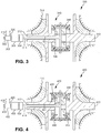
- FIG. 3 schematically illustrates a turbocharger 300 for use with an internal combustion engine 302 according to another example.
- the example shown in FIG. 3 includes similar components to the turbocharger 200 for use with the internal combustion engine 202 illustrated in FIG. 2 . Similar features of the example shown in FIG. 3 are numbered similarly in series, with the exception of the features described below.
- FIG. 3 schematically illustrates the turbocharger 300 for use with an internal combustion engine 302.
- the turbocharger 300 is in driving engagement and fluid communication with the internal combustion engine 302.
- the turbocharger 300 is in driving engagement with the internal combustion engine 302 through a differential device 340, a ratio adjusting device 306, and an infinitely variable transmission 308.
- the internal combustion engine 302 is used as a power source for a vehicle (not shown); however, it is understood that the internal combustion engine 302 may be used in other applications, such as in stationary power generation applications.
- the differential device 340 comprises a first side gear 342, a second side gear 344, a differential carrier 346, and a plurality of spider gears 348.
- the first side gear 342, the second side gear 344, the differential carrier 346, and the plurality of spider gears 348 are disposed within the housing 316, between the turbine portion 310 and the compressor portion 312.
- the first side gear 342 and the second side gear 344 are magnetic bevel gears respectively disposed on and spliningly engaged with the compressor portion 312 and the turbine portion 310.
- Each of the side gears 342, 344 comprise a plurality of magnets arranged in a circular pattern in a face of the side gears 342, 344. A polarity of alternating magnets is reversed for magnetically engaging each of the plurality of spider gears 348.
- the first side gear 342 and the second side gear 344 may be integrally formed with the compressor portion 312 and the turbine portion 310, respectively.
- the differential carrier 346 is a member in driving engagement with the output shaft 314 on which the plurality of spider gears 348 are rotatingly disposed.
- the plurality of spider gears 348 are magnetic bevel gears each in magnetic engagement with the first side gear 342 and the second side gear 344 and facilitate a differential action therebetween.
- Each of the spider gears 348 comprise a plurality of magnets arranged in a circular pattern in a face of the gears 348. A polarity of alternating magnets is reversed for magnetically engaging each of the side gears 342, 344.
- FIG. 3 illustrates the differential device 340 having two spider gears 328; however, it is understood that the differential device 340 may include three or more spider gears 348.
- FIG. 4 schematically illustrates a turbocharger 400 for use with an internal combustion engine 402 according to another example.
- the example shown in FIG. 4 includes similar components to the turbocharger 200 for use with the internal combustion engine 202 illustrated in FIG. 2 . Similar features of the example shown in FIG. 4 are numbered similarly in series, with the exception of the features described below.
- FIG. 4 schematically illustrates the turbocharger 400 for use with an internal combustion engine 402.
- the turbocharger 400 is in driving engagement and fluid communication with the internal combustion engine 402.
- the turbocharger 400 is in driving engagement with the internal combustion engine 402 through a differential device 450, a ratio adjusting device 406, and an infinitely variable transmission 408.
- the internal combustion engine 402 is used as a power source for a vehicle (not shown); however, it is understood that the internal combustion engine 402 may be used in other applications, such as in stationary power generation applications.
- the differential device 450 comprises a first side gear 452, a second side gear 454, a first intermediate ferrite member 455, a second intermediate ferrite member 456, a differential carrier 457, and a plurality of spider gears 458.
- the first side gear 452, the second side gear 454, the first intermediate ferrite member 455, the second intermediate ferrite member 456, the differential carrier 457, and the plurality of spider gears 458 are disposed within the housing 416, between the turbine portion 410 and the compressor portion 412.
- the differential carrier 457 is a member in driving engagement with the output shaft 414 on which the plurality of spider gears 458 are rotatingly disposed.
- FIG. 5 schematically illustrates a turbocharger 500 for use with an internal combustion engine 502 according to another example.
- the example shown in FIG. 5 includes similar components to the turbocharger 200 for use with the internal combustion engine 202 illustrated in FIG. 2 . Similar features of the example shown in FIG. 5 are numbered similarly in series, with the exception of the features described below.
- the first drive ring 562 is an annular member formed from a metal.
- the first drive ring 562 is disposed on and spliningly engaged with the compressor portion 512.
- a portion of an outer surface of the first drive ring 562 is configured to contact a portion of each of the plurality of balls 568.
- the portion of each of the plurality of balls 568 is in driving engagement with the first drive ring 562 through one of a boundary layer type friction and an elastohydrodynamic film.
- Such driving engagement affords a transfer of torque without slipping.
- At least a portion of the housing 516 is filled with a shear thickening fluid to facilitate the driving engagement with the first drive ring 562 and the plurality of balls 568.
- the second drive ring 564 is an annular member formed from a metal.
- the second drive ring 564 is disposed on and spliningly engaged with the turbine portion 510.
- a portion of an outer surface of the second drive ring 564 is configured to contact a portion of each of the plurality of balls 568.
- the portion of each of the plurality of balls 568 is in driving engagement with the second drive ring 564 through one of a boundary layer type friction and an elastohydrodynamic film.
- at least a portion of the housing 516 is filled with the shear thickening fluid to facilitate the driving engagement with the second drive ring 564 and the plurality of balls 568.
- the ball carrier 566 is a member in driving engagement with the output shaft 514.
- the ball carrier includes a plurality of axes 569 in a radially arrangement onto which the plurality of balls 568 are rotatingly disposed.
- FIG. 6 schematically illustrates a turbocharger 600 for use with an internal combustion engine 602 according to another example.
- the example shown in FIG. 6 includes similar components to the turbocharger 200 for use with the internal combustion engine 202 illustrated in FIG. 2 . Similar features of the example shown in FIG. 6 are numbered similarly in series, with the exception of the features described below.
- FIG. 6 schematically illustrates the turbocharger 600 for use with an internal combustion engine 602.
- the turbocharger 600 is in driving engagement and fluid communication with the internal combustion engine 602.
- the turbocharger 600 is in driving engagement with the internal combustion engine 602 through a differential device 670, a ratio adjusting device 606, and an infinitely variable transmission 608.
- the internal combustion engine 602 is used as a power source for a vehicle (not shown); however, it is understood that the internal combustion engine 602 may be used in other applications, such as in stationary power generation applications.
- the turbocharger 600 includes a turbine portion 610, a compressor portion 612, the differential device 670, an output gear 613, and an output shaft 615.
- the turbine portion 610, the compressor portion 612, the differential device 670, the output gear 613, and the output shaft 615 are rotatably mounted within a housing 616 using a plurality of bearings (not shown).
- the turbine portion 610 and the compressor portion 612 are drivingly engaged with the output shaft 615 through the differential device 670 and the output gear 613.
- the turbine portion 610 is driven by exhaust gases via an exhaust port 618 of the internal combustion engine 602.
- the turbine portion 610 is drivingly engaged with the compressor portion 612 through the differential device 670 to provide compressed air to an intake port 620 of the internal combustion engine 602.
- the output shaft 615 is also drivingly engaged with the internal combustion engine 602 through the ratio adjusting device 606 and the infinitely variable transmission 608; however, it is understood that the turbine portion 610 and the compressor portion 612 may be drivingly engaged with the internal combustion engine 602 in another manner that facilitates infinitely variable driving engagement therebetween.
- the differential device 670 comprises a first side gear 672, a second side gear 674, a differential carrier 676, a plurality of spider gears 677, and a differential housing 678.
- the first side gear 672, the second side gear 674, the differential carrier 676, and the plurality of spider gears 677 are disposed within the differential housing 678, which is rotatably disposed between the turbine portion 610 and the compressor portion 612.
- the first side gear 672 and the second side gear 674 are bevel gears respectively disposed on and spliningly engaged with the compressor portion 612 and the turbine portion 610.
- the first side gear 672 and the second side gear 674 may be integrally formed with the compressor portion 612 and the turbine portion 610, respectively.
- the differential housing 678 is a hollow member into which the first side gear 672, the second side gear 674, the differential carrier 676, and the plurality of spider gears 677 are disposed.
- An outer surface of the differential housing 678 includes a ring gear 679 coupled thereto. Alternately, it is understood that the ring gear 679 may be integrally formed with the differential housing 678.
- the ring gear 679 is in driving engagement with the output gear 613.
- the output gear 613 is drivingly engaged with the ring gear 679 and the output shaft 615.
- the output gear 613 is rotatably disposed in the housing 616 and supported by bearings (not shown).
- the output shaft 615 is a member drivingly engaged with the internal combustion engine 602 and the output gear 613.
- the output shaft 615 is drivingly engaged with the internal combustion engine 602 through the ratio adjusting device 606 and the infinitely variable transmission 608.
- FIG. 7 schematically illustrates the turbocharger 700 for use with an internal combustion engine 702.
- the turbocharger 700 is in driving engagement and fluid communication with the internal combustion engine 702.
- the turbocharger 700 is in driving engagement with the internal combustion engine 702 through a differential device 780, a ratio adjusting device 706, and an infinitely variable transmission 708.
- the internal combustion engine 702 is used as a power source for a vehicle (not shown); however, it is understood that the internal combustion engine 702 may be used in other applications, such as in stationary power generation applications.
- the turbocharger 700 includes a turbine portion 782, a compressor portion 784, the differential device 780, an output gear 713, and an output shaft 715.
- the turbine portion 782, the compressor portion 784, the differential device 780, the output gear 713, and the output shaft 715 are rotatably mounted within a housing 716 using a plurality of bearings (not shown).
- the output shaft 715 is also drivingly engaged with the internal combustion engine 702 through the ratio adjusting device 706 and the infinitely variable transmission 708; however, it is understood that the turbine portion 782 and the compressor portion 784 may be drivingly engaged internal combustion engine 702 in another manner that facilitates infinitely variable driving engagement therebetween.
- the differential device 780 comprises a first side gear 787, a second side gear 788, a differential carrier 789, a plurality of spider gears 790, a pair of intermediate ferrous members 791, and a differential housing 792.
- the first side gear 787, the second side gear 788, the differential carrier 789, and the plurality of spider gears 790 are disposed within the differential housing 792, which is rotatably disposed between the turbine portion 782 and the compressor portion 784.
- Each of intermediate ferrous members 791 is fixed with respect to the housing 716 and each is disposed between the first side gear 787 and the compressor portion 784 and the second side gear 788 and the turbine portion 782, respectively.
- the first side gear 787 and the second side gear 788 are bevel gears respectively disposed adjacent to and in magnetic driving engagement with the compressor portion 784 and the turbine portion 782.
- the first side gear 787 includes a third magnetic array 793 to facilitate driving engagement with the compressor portion 784.
- the third magnetic array 793 is cylindrical in shape and is disposed about the second magnetic array 786 of the compressor portion 784.
- the second side gear 788 includes a fourth magnetic array 794 to facilitate driving engagement with the turbine portion 782.
- the fourth magnetic array 795 is cylindrical in shape and is disposed about the first magnetic array 785 of the turbine portion 782.
- the third magnetic array 793, one of the intermediate ferrous members 791, and the second magnetic array 786 form a magnetic drive ratio adjusting device, which is used to adjust a drive ratio between the compressor portion 784 and the first side gear 787.
- the magnetic drive ratio adjusting device is used to cause a speed reduction between the compressor portion 784 and the first side gear 787. It is understood that other magnetic arrangements may be used to cause a speed reduction between the compressor portion 784 and the first side gear 787.
- the fourth magnetic array 795, one of the intermediate ferrous members 791, and the first magnetic array 785 form a magnetic drive ratio adjusting device, which is used to adjust a drive ratio between the turbine portion 782 and the second side gear 788.
- the magnetic drive ratio adjusting device is used to cause a speed reduction between the turbine portion 782 and the second side gear 788. It is understood that other magnetic arrangements may be used to cause a speed reduction between the turbine portion 782 and the second side gear 788. Further, it is understood that the principles of the magnetic drive ratio adjusting device may be applied to any of the examples described hereinabove.
- the differential carrier 789 is a member in driving engagement with the differential housing 792.
- the plurality of spider gears 790 is rotatingly disposed on the differential carrier 789.
- the plurality of spider gears 790 are bevel gears each in driving engagement with the first side gear 787 and the second side gear 788 and facilitate a differential action therebetween.
- FIG. 7 illustrates the differential device 780 having two spider gears 790; however, it is understood that the differential device 780 may include three or more spider gears 790.
- the differential housing 792 is a hollow member into which the first side gear 787, the second side gear 788, the differential carrier 789, and the plurality of spider gears 790 are disposed.
- An outer surface of the differential housing 792 includes a ring gear 795 coupled thereto.
- the ring gear 795 may be integrally formed with the differential housing 792.
- the ring gear 795 is in driving engagement with the output gear 713.
- the output gear 713 is drivingly engaged with the ring gear 795 and the output shaft 715.
- the output gear 713 is rotatably disposed in the housing 716 and supported by bearings (not shown).
- the output shaft 715 is a member drivingly engaged with the internal combustion engine 702 and the output gear 713.
- the output shaft 715 is drivingly engaged with the internal combustion engine 702 through the ratio adjusting device 706 and the infinitely variable transmission 708.
- the manner of providing driving engagement between the internal combustion engine 602, 702 and the differential device 670, 780 may be adapted to provide driving engagement between the internal combustion engine 202, 302, 402, 502 and the differential device 204, 340, 450, 560.
- the turbocharger 200, 300, 400, 500, 600, 700 is drivingly engaged with the internal combustion engine 202, 302, 402, 502, 602, 702 through the infinitely variable transmission 208, 308, 408, 508, 608, 708 for at least two purposes: a first purpose is to allow the compressor portion 212, 312, 412, 512, 612, 784 to be at least partially driven by the internal combustion engine 202, 302, 402, 502, 602, 702; a second purpose is to allow the turbine portion 210, 310, 410, 510, 610, 782 to be drivingly engaged with the internal combustion engine 202, 302, 402, 502, 602, 702, or an output (not shown) thereof, through the infinitely variable transmission 208, 308, 408, 508, 608, 708.
- differential device 204, 340, 450, 560, 670, 780 allow for the turbine portion 210, 310, 410, 510, 610, 782 and the compressor portion 212, 312, 412, 512, 612, 784 to rotate at different speeds, which increases a performance of the turbocharger 200, 300, 400, 500, 600, 700.
- FIG. 8 illustrates an exemplary speed diagram of the compressor portion 212, 312, 412, 512, 612, 784, the carrier 226, 346, 457, 566, 676, 789, and the turbine portion 210, 310, 410, 510, 610, 782 of the differential device 204, 340, 450, 560, 670, 780 during three different modes of operation of the turbocharger 200, 300, 400, 500, 600, 700.
- a control system in communication with the infinitely variable transmission 208, 308, 408, 508, 608, 708 is used to control a rotational speed of the carrier 226, 346, 457, 566, 676, 789 (and thus a rotational speed of the compressor portion 212, 312, 412, 512, 612, 784.
- the control system may adjust the infinitely variable transmission 208, 308, 408, 508, 608, 708 based on at least one of a driver action, a speed of a vehicle the turbocharger 200, 300, 400, 500, 600, 700 is incorporated in, a rotational speed of the compressor portion 212, 312, 412, 512, 612, 784, and a rotational speed of the turbine portion 210, 310, 410, 510, 610, 782.
- the driver action may a throttle adjustment.
- the three horizontal axes of FIG. 8 represent respectively, from top to bottom, a rotation speed of the compressor portion 212, 312, 412, 512, 612, 784 (and the side gear 222, 342, 452, 672, 787 or the drive ring 562), a rotation speed of the carrier 226, 346, 457, 566, 676, 789, and a rotation speed of the turbine portion 210, 310, 410, 510, 610, 782 (and the side gear 224, 344, 454, 674, 788 or the drive ring 564).
- the rotation speed of the turbine portion 210, 310, 410, 510, 610, 782 is determined by the exhaust gases flowing through the turbine portion 210, 310, 410, 510, 610, 782.
- the rotational speed of the compressor portion 212, 312, 412, 512, 612, 784 may be varied while keeping the rotational speed of the turbine portion 210, 310, 410, 510, 610, 782 substantially constant.
- a first mode of operation of the turbocharger 200, 300, 400, 500, 600, 700 is represented on the speed diagram at point A.
- the rotational speed of the carrier 226, 346, 457, 566, 676, 789 is substantially equal to zero, which is indicative that a ratio of the infinitely variable transmission 208, 308, 408, 508, 608, 708 is substantially equal to zero.
- the compressor portion 212, 312, 412, 512, 612, 784 is rotating at the same speed as the turbine portion 210, 310, 410, 510, 610, 782, but in an opposite direction.
- energy coming from the turbine portion 210, 310, 410, 510, 610, 782 is entirely applied to the compressor portion 212, 312, 412, 512, 612, 784, only with an opposite direction of rotation.
- a second mode of operation of the turbocharger 200, 300, 400, 500, 600, 700 is represented on the speed diagram by a range of speeds at B.
- the rotational speed of the carrier 226, 346, 457, 566, 676, 789 is a negative value (with respect to the turbine portion 210, 310, 410, 510, 610, 782).
- energy is applied from the internal combustion engine 202, 302, 402, 502, 602, 702 to accelerate the compressor portion 212, 312, 412, 512, 612, 784 and to provide additional boost.
- Energy applied from the internal combustion engine 202, 302, 402, 502, 602, 702 reduces a turbo lag of the turbocharger 200, 300, 400, 500, 600, 700.
- Energy applied from the internal combustion engine 202, 302, 402, 502, 602, 702 is in addition to energy applied by the turbine portion 210, 310, 410, 510, 610, 782.
- the rotational speed of the carrier 226, 346, 457, 566, 676, 789 is the product of the speed of the internal combustion engine 202, 302, 402, 502, 602, 702, a ratio employed by the infinitely variable transmission 208, 308, 408, 508, 608, 708, and a ratio employed by the ratio adjusting device 206, 306, 406, 506, 606, 706. It is understood that each of the aforementioned ratios may be determined in order to increase an effectiveness of the turbocharger 200, 300, 400, 500, 600, 700.
- a third mode of operation of the turbocharger 200, 300, 400, 500, 600, 700 is represented on the speed diagram by a range of speeds at C.
- the rotational speed of the carrier 226, 346, 457, 566, 676, 789 is a positive value (with respect to the turbine portion 210, 310, 410, 510, 610, 782).
- energy is applied from the turbine portion 210, 310, 410, 510, 610, 782 to the internal combustion engine 202, 302, 402, 502, 602, 702.
- the amount of energy applied from the turbine portion 210, 310, 410, 510, 610, 782 is a surplus amount of energy not required by the compressor portion 212, 312, 412, 512, 612, 784.
- substantially all or a very large percentage of energy from the turbine portion 210, 310, 410, 510, 610, 782 is applied to the carrier 226, 346, 457, 566, 676, 789, the ratio adjusting device 206, 306, 406, 506, 606, 706, the infinitely variable transmission 208, 308, 408, 508, 608, 708, and the internal combustion engine 202, 302, 402, 502, 602, 702.
- the third mode of operation allows energy to be recuperated and to be applied to the internal combustion engine 202, 302, 402, 502, 602, 702, or the output thereof.
- the rotational speed of the carrier 226, 346, 457, 566, 676, 789 is the product of the speed of the internal combustion engine 202, 302, 402, 502, 602, 702, a ratio employed by the infinitely variable transmission 208, 308, 408, 508, 608, 708, and a ratio employed by the ratio adjusting device 206, 306, 406, 506, 606, 706. It is understood that each of the aforementioned ratios may be determined in order to increase an effectiveness of the turbocharger 200, 300, 400, 500, 600, 700.
- the turbocharger 200, 300, 400, 500, 600, 700 also prevents a maximum boost pressure from being exceeded by being able to direct at least a portion of the energy recuperated in the turbine portion 210, 310, 410, 510, 610, 782 to the internal combustion engine 202, 302, 402, 502, 602, 702. Further, the turbocharger 200, 300, 400, 500, 600, 700 is able to adapt a speed of the compressor portion 212, 312, 412, 512, 612, 784 to achieve a required compression by adjusting a ratio of the infinitely variable transmission 208, 308, 408, 508, 608, 708.
Landscapes
- Engineering & Computer Science (AREA)
- General Engineering & Computer Science (AREA)
- Mechanical Engineering (AREA)
- Chemical & Material Sciences (AREA)
- Combustion & Propulsion (AREA)
- Software Systems (AREA)
- Theoretical Computer Science (AREA)
- Power Engineering (AREA)
- General Chemical & Material Sciences (AREA)
- Chemical Kinetics & Catalysis (AREA)
- Computer Security & Cryptography (AREA)
- Physics & Mathematics (AREA)
- General Physics & Mathematics (AREA)
- Supercharger (AREA)
- Information Transfer Between Computers (AREA)
Priority Applications (1)
| Application Number | Priority Date | Filing Date | Title |
|---|---|---|---|
| EP18193076.9A EP3431734A1 (en) | 2013-02-08 | 2014-02-07 | Internal combustion engine coupled turbocharger with an infinitely variable transmission |
Applications Claiming Priority (2)
| Application Number | Priority Date | Filing Date | Title |
|---|---|---|---|
| US201361762379P | 2013-02-08 | 2013-02-08 | |
| PCT/US2014/015352 WO2014124291A1 (en) | 2013-02-08 | 2014-02-07 | Internal combustion engine coupled turbocharger with an infinitely variable transmission |
Related Child Applications (2)
| Application Number | Title | Priority Date | Filing Date |
|---|---|---|---|
| EP18193076.9A Division EP3431734A1 (en) | 2013-02-08 | 2014-02-07 | Internal combustion engine coupled turbocharger with an infinitely variable transmission |
| EP18193076.9A Division-Into EP3431734A1 (en) | 2013-02-08 | 2014-02-07 | Internal combustion engine coupled turbocharger with an infinitely variable transmission |
Publications (2)
| Publication Number | Publication Date |
|---|---|
| EP2954180A1 EP2954180A1 (en) | 2015-12-16 |
| EP2954180B1 true EP2954180B1 (en) | 2018-11-14 |
Family
ID=50189765
Family Applications (2)
| Application Number | Title | Priority Date | Filing Date |
|---|---|---|---|
| EP14707270.6A Not-in-force EP2954180B1 (en) | 2013-02-08 | 2014-02-07 | Internal combustion engine coupled turbocharger with an infinitely variable transmission |
| EP18193076.9A Withdrawn EP3431734A1 (en) | 2013-02-08 | 2014-02-07 | Internal combustion engine coupled turbocharger with an infinitely variable transmission |
Family Applications After (1)
| Application Number | Title | Priority Date | Filing Date |
|---|---|---|---|
| EP18193076.9A Withdrawn EP3431734A1 (en) | 2013-02-08 | 2014-02-07 | Internal combustion engine coupled turbocharger with an infinitely variable transmission |
Country Status (4)
| Country | Link |
|---|---|
| US (2) | US9404414B2 (https=) |
| EP (2) | EP2954180B1 (https=) |
| JP (2) | JP6317371B2 (https=) |
| WO (2) | WO2014124063A1 (https=) |
Families Citing this family (32)
| Publication number | Priority date | Publication date | Assignee | Title |
|---|---|---|---|---|
| US9347532B2 (en) | 2012-01-19 | 2016-05-24 | Dana Limited | Tilting ball variator continuously variable transmission torque vectoring device |
| EP2815152A1 (en) | 2012-02-15 | 2014-12-24 | Dana Limited | Transmission and driveline having a tilting ball variator continuously variable transmission |
| US9556941B2 (en) | 2012-09-06 | 2017-01-31 | Dana Limited | Transmission having a continuously or infinitely variable variator drive |
| US9599204B2 (en) | 2012-09-07 | 2017-03-21 | Dana Limited | Ball type CVT with output coupled powerpaths |
| CN104755812A (zh) | 2012-09-07 | 2015-07-01 | 德纳有限公司 | 包括动力分流路径的基于球型cvp的ivt |
| CN104769329B (zh) | 2012-09-07 | 2017-06-23 | 德纳有限公司 | 球型连续式无级变速器/无限式无级变速器 |
| WO2014039900A1 (en) | 2012-09-07 | 2014-03-13 | Dana Limited | Ball type cvt with powersplit paths |
| CN104769326B (zh) | 2012-09-07 | 2017-04-19 | 德纳有限公司 | 包括直接驱动模式的球型cvt |
| WO2014078583A1 (en) | 2012-11-17 | 2014-05-22 | Dana Limited | Continuously variable transmission |
| WO2014124063A1 (en) | 2013-02-08 | 2014-08-14 | Microsoft Corporation | Pervasive service providing device-specific updates |
| CN105121905A (zh) | 2013-03-14 | 2015-12-02 | 德纳有限公司 | 球型连续式无级变速器 |
| US9752500B2 (en) * | 2013-03-14 | 2017-09-05 | Pratt & Whitney Canada Corp. | Gas turbine engine with transmission and method of adjusting rotational speed |
| WO2014159756A2 (en) | 2013-03-14 | 2014-10-02 | Dana Limited | Continuously variable transmission and an infinitely variable transmission variatory drive |
| WO2014197711A1 (en) | 2013-06-06 | 2014-12-11 | Dana Limited | 3-mode front wheel drive and rear wheel drive continuously variable planetary transmission |
| WO2015073883A1 (en) | 2013-11-18 | 2015-05-21 | Dana Limited | Infinite variable transmission with planetary gear set |
| US10088022B2 (en) | 2013-11-18 | 2018-10-02 | Dana Limited | Torque peak detection and control mechanism for a CVP |
| US9796477B2 (en) * | 2014-11-20 | 2017-10-24 | Hamilton Sundstrand Corporation | Engine driven-shaft driven compressor utilizing infinitely variable transmission |
| US10224798B2 (en) | 2015-06-23 | 2019-03-05 | Michael F. Leas | Magnetic spiral bevel gear |
| CN106438041A (zh) * | 2015-08-12 | 2017-02-22 | 熵零股份有限公司 | 叶轮发动机 |
| US9664253B2 (en) * | 2015-09-11 | 2017-05-30 | Gkn Driveline North America, Inc. | Crowned profile driveshaft journal |
| US10030594B2 (en) | 2015-09-18 | 2018-07-24 | Dana Limited | Abuse mode torque limiting control method for a ball-type continuously variable transmission |
| CN105204915A (zh) * | 2015-10-29 | 2015-12-30 | 小米科技有限责任公司 | 应用程序更新方法、装置及系统 |
| CN105610866A (zh) * | 2016-02-18 | 2016-05-25 | 四川长虹电器股份有限公司 | 实现智能设备自动接入家庭无线局域网系统及方法 |
| US20170363098A1 (en) * | 2016-06-20 | 2017-12-21 | United Technologies Corporation | Booster compressor with speed change system |
| GB2561532B (en) * | 2017-01-30 | 2019-06-19 | Jaguar Land Rover Ltd | Waste heat recovery system |
| TWI655116B (zh) | 2017-05-19 | 2019-04-01 | 財團法人工業技術研究院 | 一種傳動機構及其應用之單向組件 |
| TWI665399B (zh) | 2018-05-16 | 2019-07-11 | 財團法人工業技術研究院 | 雙軸變速箱機構 |
| CN109681448A (zh) * | 2018-11-06 | 2019-04-26 | 樊品良 | 一种空氧泵 |
| CN110748417B (zh) * | 2019-12-24 | 2020-04-10 | 沈阳微控新能源技术有限公司 | 一种基于磁耦合联轴器的涡轮增压器和发动机 |
| US11480098B1 (en) | 2021-07-23 | 2022-10-25 | Mustafa Ali Al-Huwaider | Continuously variable transmission (CVT) driven supercharger through transmission output |
| US11773793B2 (en) * | 2022-02-04 | 2023-10-03 | Ford Global Technologies, Llc | Method and system for compressed air supply |
| US12392283B1 (en) * | 2024-05-15 | 2025-08-19 | Flowserve Pte. Ltd. | Energy recovery turbocharger with integral motor/generator |
Family Cites Families (282)
| Publication number | Priority date | Publication date | Assignee | Title |
|---|---|---|---|---|
| US1063244A (en) | 1908-03-18 | 1913-06-03 | Ludwig Maria Dieterich | Variable-power transmitting and controlling mechanism. |
| US1215969A (en) | 1916-12-14 | 1917-02-13 | Thomas E Murray | Sheet-metal piston. |
| US1526140A (en) | 1921-10-03 | 1925-02-10 | Hollow Ball Company Inc | Manufacture of hollow metal balls |
| US2060884A (en) | 1933-09-19 | 1936-11-17 | Erban Operating Corp | Power transmission mechanism |
| US2019006A (en) | 1934-02-01 | 1935-10-29 | Ferrarl Lorenzo | Change speed gear |
| FR796188A (fr) | 1935-10-04 | 1936-03-31 | Changement de vitesse à friction | |
| US2148759A (en) | 1938-02-10 | 1939-02-28 | Grand Cecil W Le | Variable transmission unit |
| US2405201A (en) | 1942-08-29 | 1946-08-06 | Imp Brass Mfg Co | Method of forming closed metal capsules |
| CH290407A (de) | 1950-09-20 | 1953-04-30 | Ag Dabo | Mechanisches stufenloses Wechselgetriebe. |
| FR1030702A (fr) | 1950-12-06 | 1953-06-16 | Tiltman Langley Lab Ltd | Perfectionnements aux mécanismes de transmission à rapport de vitesses variable dans une gamme continue |
| US2729118A (en) * | 1955-04-25 | 1956-01-03 | Lyell M Emslie | Gearless differential |
| US2931235A (en) | 1957-11-12 | 1960-04-05 | George Cohen 600 Group Ltd | Variable speed friction drive transmissions |
| DE1237380B (de) * | 1958-08-13 | 1967-03-23 | Differential Diesel Engines Es | Aufgeladene Brennkraftmaschine mit einem Aufladesystem mit zwei Antrieben |
| US3203278A (en) | 1963-01-02 | 1965-08-31 | Ford Motor Co | Variable speed friction drive transmission |
| FR1472282A (fr) | 1966-02-24 | 1967-03-10 | Chambre Syndicale Des Fabrican | Procédé et appareillage pour la transformation d'un tronçon de tube métallique en sphère, et application de la sphère ainsi obtenue à la réalisation de noeuds d'assemblage notamment pour charpentes tubulaires |
| US3376633A (en) | 1966-04-20 | 1968-04-09 | Richard H. Wesley | Ball joint forming methods |
| GB1127825A (en) | 1966-06-15 | 1968-09-18 | Filden Engineering Ltd | Improvements relating to the manufacture of spherical and spheroidal objects |
| US3407687A (en) | 1967-03-27 | 1968-10-29 | Hayashi Tadashi | Variable ratio power transmission device |
| US3470720A (en) | 1967-09-01 | 1969-10-07 | Phillip R Eklund | Method of making hollow balls for use in ball bearing and/or similar rolling operations |
| US3505718A (en) | 1968-01-15 | 1970-04-14 | Gen Ind Inc | One-piece sheet metal hollow ball for ball valves |
| US3583060A (en) | 1968-12-30 | 1971-06-08 | Ametek Inc | Method of swaging a metal fitting on a steel wire |
| US3688600A (en) | 1971-04-26 | 1972-09-05 | Ford Motor Co | Infinitely variable overdrive transmission mechanism |
| US3765270A (en) | 1971-04-26 | 1973-10-16 | Ford Motor Co | Multiple ratio power transmission mechanism with an infinitely variable overdrive range |
| FR2185076A5 (https=) | 1972-05-16 | 1973-12-28 | Burke John | |
| US3774280A (en) | 1972-07-18 | 1973-11-27 | Us Air Force | Method of fabricating hollow balls for use in rolling contact bearing applications |
| US3831245A (en) | 1973-03-01 | 1974-08-27 | Columbus Auto Parts | Method of producing ball joints |
| US3894559A (en) | 1974-03-28 | 1975-07-15 | Leland Q Depuy | Manifold valve |
| FR2280451A1 (fr) | 1974-08-01 | 1976-02-27 | Roche Jean | Procede et moyens de fabrication de corps spheriques et de revolution pleins ou creux |
| JPS5266804U (https=) * | 1975-11-14 | 1977-05-18 | ||
| US4046988A (en) | 1976-03-05 | 1977-09-06 | Kobe Steel Ltd. | Method of preventing base metal end crack in arc welding and end tab used therefor |
| GB1592180A (en) | 1976-12-14 | 1981-07-01 | Gaasenbeek Johannes L | Skidsteering apparatus |
| US4187709A (en) | 1976-08-23 | 1980-02-12 | Kevin Strickland | Explosive forming |
| US4344336A (en) | 1979-07-23 | 1982-08-17 | Ford Motor Company | Differential traction drive with extreme overall torque ratios for use in a gas turbine engine driveline |
| US4368572A (en) | 1979-10-15 | 1983-01-18 | Toyo Kogyo Co., Ltd. | Method of manufacturing a shaft structure having a spherical bulb |
| IT1119624B (it) | 1979-12-18 | 1986-03-10 | Fiat Allis Macch Movi | Cambio di velocita del tipo con comando idraulico per l'innesto delle marce e contralbero |
| DE3169011D1 (en) | 1980-05-31 | 1985-03-28 | Bl Tech Ltd | Control systems for continuously variable ratio transmissions |
| US4360090A (en) | 1980-10-20 | 1982-11-23 | General Motors Corporation | Torque reversal control valve for a torque converter clutch |
| DE3245045A1 (de) | 1982-12-06 | 1984-06-07 | Adam Opel AG, 6090 Rüsselsheim | Kraftfahrzeug-hybridantriebsvorrichtung |
| EP0156936B1 (de) | 1984-04-03 | 1987-12-09 | Klinger AG | Verfahren zum Herstellen eines kugelförmigen Schaltgliedes für Fluid-Absperrorgane |
| US4693134A (en) | 1985-06-20 | 1987-09-15 | Excelermatic Inc. | High-powered vehicle drive train |
| AU6019686A (en) | 1985-07-22 | 1987-01-29 | Borg-Warner Corporation | Dual pass continuously variable transmission with asymmetric variator |
| GB8522747D0 (en) | 1985-09-13 | 1985-10-16 | Fellows T G | Transmission systems |
| US4731044A (en) | 1985-12-18 | 1988-03-15 | Borg-Warner Automotive, Inc. | Tension sensor and control arrangement for a continuously variable transmission |
| US4784017A (en) | 1986-07-03 | 1988-11-15 | Johnshoy Edward W | Continuously variable transmission and torque retaining differential |
| GB2196892B (en) | 1986-11-05 | 1990-01-17 | Concentric Pumps Ltd | Fixing components on shafts |
| DE3706716A1 (de) | 1987-03-02 | 1988-09-15 | Planetroll Antriebe Gmbh | Getriebe |
| US4856371A (en) | 1987-03-12 | 1989-08-15 | Tractiontec Corporation | Traction drive transmission system |
| WO1988009886A1 (en) | 1987-06-04 | 1988-12-15 | The Gleason Works | Continuously variable differential |
| EP0347186B1 (en) | 1988-06-17 | 1994-08-17 | Malcolm Tomlinson | Variable ratio power transmission |
| JP2832980B2 (ja) | 1988-10-26 | 1998-12-09 | トヨタ自動車株式会社 | 車両用遊星歯車式変速装置 |
| US5109962A (en) | 1989-12-28 | 1992-05-05 | Fuji Jukogyo Kabushiki Kaisha | Transmission ratio control system for a continuously variable transmission |
| GB9018082D0 (en) | 1990-08-17 | 1990-10-03 | Fellows Thomas G | Improvements in or relating to transmissions of the toroidal-race,rolling-traction type |
| GB9019943D0 (en) | 1990-09-12 | 1990-10-24 | Tomlinson Malcolm | Double toric-type traction variators |
| US5217412A (en) | 1990-10-20 | 1993-06-08 | Luk Lamellen Und Kupplungsbau Gmbh | Continuously variable speed transmission |
| JP2768012B2 (ja) | 1990-12-25 | 1998-06-25 | 日産自動車株式会社 | 無段変速機 |
| US5238460A (en) | 1991-02-28 | 1993-08-24 | Mazda Motor Corporation | Power transmission system for vehicle |
| JPH04357347A (ja) * | 1991-05-31 | 1992-12-10 | Fuji Oozx Kk | 動力伝達装置 |
| DE4120589A1 (de) | 1991-06-21 | 1993-01-07 | Porsche Ag | Verfahren zur steuerung eines stufenlosen getriebes eines kraftfahrzeugs |
| DE4126993A1 (de) | 1991-08-16 | 1993-02-18 | Fichtel & Sachs Ag | Antriebsnabe für ein Fahrzeug, insbesondere Fahrrad, mit stufenlos einstellbarem Übersetzungsverhältnis. |
| US5168778A (en) | 1991-08-29 | 1992-12-08 | Borg-Warner Automotive, Inc. | CVT downshift control strategy to minimize slip at the drive pulley |
| DE4226453A1 (de) | 1992-08-10 | 1994-02-17 | Sauer Sundstrand Gmbh & Co | Antriebseinrichtung für einen automativen Fahrantrieb, z. B. bei einem Gabelstapler oder Radlader |
| US5683322A (en) | 1993-04-21 | 1997-11-04 | Meyerle; Michael | Continuous hydrostatic-mechanical branch power split transmission particularly for power vehicles |
| IN189939B (https=) | 1993-12-20 | 2003-05-17 | Torotrak Dev Ltd | |
| US5577423A (en) | 1994-03-04 | 1996-11-26 | Mimura; Kenji | Differential gear |
| US5588929A (en) | 1994-11-28 | 1996-12-31 | Chrysler Corporation | Four-speed automatic transmission |
| US5520588A (en) | 1995-05-03 | 1996-05-28 | General Motors Corporation | Power transmission |
| JPH0937407A (ja) | 1995-07-18 | 1997-02-07 | Toyota Motor Corp | 回生制動制御装置 |
| US5927357A (en) | 1997-12-30 | 1999-07-27 | Black & Decker Inc. | Portable wood planing machine |
| US5776028A (en) | 1995-09-01 | 1998-07-07 | Honda Giken Kogyo Kabushiki Kaisha | Belt-type continuously variable transmission |
| US5599251A (en) | 1995-09-27 | 1997-02-04 | Ford Motor Company | Six speed automatic transmission for automotive vehicles |
| JPH09119506A (ja) | 1995-10-23 | 1997-05-06 | Toyota Motor Corp | 差動装置 |
| JP3213227B2 (ja) | 1995-11-21 | 2001-10-02 | 本田技研工業株式会社 | 自動変速機のトルク検出及び制御装置 |
| US5659956A (en) | 1996-02-12 | 1997-08-26 | Braginsky; Mikhail | Process for the production of hollow ball bearings |
| US5730678A (en) | 1996-02-28 | 1998-03-24 | Gen Dynamics Defense Syst Inc | Multi-range, hydromechanical transmission for motor vehicles |
| JP2000508743A (ja) | 1996-04-22 | 2000-07-11 | ツェットエフ、フリードリッヒスハーフェン、アクチエンゲゼルシャフト | 遊星歯車装置及びクラッチ/ブレーキ装置 |
| KR0183215B1 (ko) | 1996-06-18 | 1999-04-01 | 박병재 | 차량용 무단 변속기 |
| DE19703544A1 (de) | 1997-01-31 | 1998-08-06 | Zahnradfabrik Friedrichshafen | Reibradgetriebe |
| CA2240977C (en) | 1997-06-18 | 2002-01-22 | Jacob S. Belinky | Removable trailer hitch ball |
| US6551210B2 (en) | 2000-10-24 | 2003-04-22 | Motion Technologies, Llc. | Continuously variable transmission |
| DE19743058A1 (de) | 1997-09-30 | 1999-04-01 | Bosch Gmbh Robert | Vorrichtung und Verfahren zur Verstellung der Übersetzung eines CVT |
| US5996226A (en) | 1997-12-23 | 1999-12-07 | Itt Manufacturing Enterprises, Inc. | Method of manufacturing push rod balls |
| JP3391244B2 (ja) | 1997-12-25 | 2003-03-31 | 日産自動車株式会社 | ハイブリッド車両の制御装置 |
| US5971883A (en) | 1998-03-13 | 1999-10-26 | General Motors Corporation | Multi-speed power transmission |
| US6036616A (en) | 1998-03-19 | 2000-03-14 | Ford Global Technologies, Inc. | All wheel drive continously variable transmission having dual mode operation |
| US6071208A (en) | 1998-06-22 | 2000-06-06 | Koivunen; Erkki | Compact multi-ratio automatic transmission |
| JP3001859B1 (ja) | 1998-08-18 | 2000-01-24 | 本田技研工業株式会社 | 車両用無段変速機の変速制御装置 |
| US5961415A (en) | 1998-09-17 | 1999-10-05 | Ford Global Technologies, Inc. | Single cavity toroidal traction drive continually variable transmission |
| DE19844618A1 (de) | 1998-09-29 | 2000-03-30 | Zahnradfabrik Friedrichshafen | Verfahren zur Reduzierung der thermischen Belastung eines Automatgetriebes für ein Kraftfahrzeug in einem Notfahrbetrieb |
| JP2000120822A (ja) | 1998-10-21 | 2000-04-28 | Nsk Ltd | 無段変速装置 |
| US6059685A (en) | 1999-05-06 | 2000-05-09 | Ford Global Technologies, Inc. | Coaxial traction drive automatic transmission for automotive vehicles |
| US6371880B1 (en) | 1999-06-03 | 2002-04-16 | Hyundai Motor Company | Limited slip differential |
| US6045477A (en) | 1999-06-14 | 2000-04-04 | General Motors Corporation | Continuously variable multi-range powertrain with a geared neutral |
| US6083135A (en) | 1999-06-18 | 2000-07-04 | Ford Global Technologies, Inc. | Multiple speed overdrive transmission for a motor vehicle |
| US6053839A (en) | 1999-06-18 | 2000-04-25 | Ford Global Technologies, Inc. | Multiple speed overdrive transmission for a motor vehicle |
| DE19929424A1 (de) | 1999-06-26 | 2001-01-11 | Bosch Gmbh Robert | Reibrad-Umlaufgetriebe mit Kegelrädern |
| KR100341749B1 (ko) | 1999-07-08 | 2002-06-24 | 이계안 | 자동변속기용 기어 트레인 |
| JP4345146B2 (ja) | 1999-07-29 | 2009-10-14 | アイシン精機株式会社 | 変速装置 |
| US6217474B1 (en) | 1999-10-22 | 2001-04-17 | General Motors Corporation | Multi speed power transmission |
| DE10021912A1 (de) | 2000-05-05 | 2001-11-08 | Daimler Chrysler Ag | Stufenloses Fahrzeuggetriebe |
| US6358178B1 (en) | 2000-07-07 | 2002-03-19 | General Motors Corporation | Planetary gearing for a geared neutral traction drive |
| JP3678122B2 (ja) | 2000-07-10 | 2005-08-03 | 日産自動車株式会社 | 変速比無限大無段変速機のトルク制御装置 |
| DE10040039A1 (de) | 2000-08-11 | 2002-02-21 | Daimler Chrysler Ag | Wechselgetriebe-Anordnung |
| KR100374770B1 (ko) | 2000-08-22 | 2003-03-06 | 구택서 | 기어 치합을 통해 신뢰성 있는 무단 변속 동작을 수행하는 변속기와, 그를 이용한 차량용 무단 변속 장치 |
| US6554735B2 (en) | 2000-09-28 | 2003-04-29 | Fuji Jukogyo Kabushiki Kaisha | Planetary gear type differential apparatus |
| DE10056002A1 (de) | 2000-11-11 | 2002-05-23 | Bosch Gmbh Robert | Radareinrichtung und Verfahren zum Betreiben einer Radareinrichtung |
| US6447422B1 (en) | 2001-01-16 | 2002-09-10 | General Motors Corporation | Dual mode, geared neutral continuously variable transmission |
| US6752696B2 (en) | 2001-03-12 | 2004-06-22 | Nsk Ltd. | Rolling elements for rolling bearing, method of producing the same, and rolling bearing |
| JP2002274353A (ja) | 2001-03-16 | 2002-09-25 | Nissan Motor Co Ltd | 車両用制駆動力制御装置 |
| EP2261537A3 (en) | 2001-04-26 | 2012-06-13 | Fallbrook Technologies Inc. | Continuously variable transmission |
| DE10121042C1 (de) | 2001-04-28 | 2003-05-08 | Daimler Chrysler Ag | Wechselgetriebe-Anordnung mit einem stufenlosen Toroidgetriebe und einem Planetenräder-Summengetriebe |
| EP1258658A3 (en) | 2001-05-14 | 2009-07-15 | Nissan Motor Company, Limited | Auxiliary Transmission |
| JP2002340138A (ja) | 2001-05-21 | 2002-11-27 | Honda Motor Co Ltd | 車両用自動変速装置 |
| JP2003097669A (ja) | 2001-09-27 | 2003-04-03 | Jatco Ltd | トルクスプリット式変速比無限大無段変速機 |
| US6895218B2 (en) | 2001-10-11 | 2005-05-17 | Sprint Spectrum L.P. | Method for in-building distribution using wireless access technology |
| US6866606B2 (en) | 2001-10-25 | 2005-03-15 | Honda Giken Kogyo Kabushiki Kaisha | Continuously variable transmission system for vehicles |
| JP2003127688A (ja) | 2001-10-25 | 2003-05-08 | Tochigi Fuji Ind Co Ltd | 動力伝達装置 |
| US6641497B2 (en) | 2001-12-07 | 2003-11-04 | Murray, Inc. | Epicyclic transmission for zero turning radius vehicles |
| JP2003176862A (ja) | 2001-12-11 | 2003-06-27 | Jatco Ltd | 動力伝達装置 |
| DE10206202A1 (de) | 2002-02-15 | 2003-08-28 | Daimler Chrysler Ag | Kraftfahrzeuggetriebe mit einem Toroidvariator |
| US20030200783A1 (en) | 2002-04-26 | 2003-10-30 | Dean Shai | Hollow tubular blank provided in wall thereof with one or more reinforcing ribs |
| US20030213125A1 (en) | 2002-05-20 | 2003-11-20 | Su-Yueh Chiuchang | Ball valve body manufacturing method |
| US6931316B2 (en) | 2002-06-05 | 2005-08-16 | Nissan Motor Co., Ltd. | Toroidal continuously variable transmission control apparatus |
| US7720522B2 (en) | 2003-02-25 | 2010-05-18 | Medtronic, Inc. | Fiducial marker devices, tools, and methods |
| JP3921148B2 (ja) | 2002-08-07 | 2007-05-30 | ジヤトコ株式会社 | パワースプリット型無段変速装置 |
| US6962545B2 (en) | 2002-09-23 | 2005-11-08 | Bae Systems Onctrols | Multi-range parallel-hybrid continuously variable transmission |
| ES2431114T3 (es) | 2002-09-30 | 2013-11-25 | Ulrich Rohs | Transmisión |
| DE10249484A1 (de) | 2002-10-24 | 2004-05-06 | Zf Friedrichshafen Ag | Leistungsverzweigtes 2-Bereichs-Getriebe |
| US6986725B2 (en) | 2002-11-01 | 2006-01-17 | Eaton Corporation | Continuously variable stepped transmission |
| JP3896958B2 (ja) | 2002-12-05 | 2007-03-22 | 日本精工株式会社 | 無段変速装置 |
| US6783477B2 (en) | 2002-12-18 | 2004-08-31 | General Motors Corporation | Family of six-speed dual-clutch transmissions having three planetary gear sets |
| DE10358114A1 (de) | 2002-12-23 | 2004-07-01 | Luk Lamellen Und Kupplungsbau Beteiligungs Kg | Getriebe mit stufenlos verstellbarer Übersetzung, mit oder ohne Leistungsverzweigung sowie mit und ohne E-Maschine |
| US7011600B2 (en) | 2003-02-28 | 2006-03-14 | Fallbrook Technologies Inc. | Continuously variable transmission |
| DE10315313A1 (de) | 2003-04-04 | 2005-01-20 | Zf Friedrichshafen Ag | Getriebe, insbesondere automatisiertes leistungsverzweigtes Mehrganggetriebe |
| EP1620629B1 (en) | 2003-04-25 | 2009-04-22 | Intersyn Technologies | System and method using a continuously variable transmission to control one or more system components |
| GB0315408D0 (en) | 2003-07-01 | 2003-08-06 | Torotrak Dev Ltd | Continuously variable ratio transmission system |
| JP4370842B2 (ja) | 2003-07-14 | 2009-11-25 | 日本精工株式会社 | 無段変速装置 |
| US7166052B2 (en) | 2003-08-11 | 2007-01-23 | Fallbrook Technologies Inc. | Continuously variable planetary gear set |
| JP4304051B2 (ja) | 2003-11-12 | 2009-07-29 | 本田技研工業株式会社 | 変速機 |
| JP3991975B2 (ja) | 2003-11-12 | 2007-10-17 | 日産自動車株式会社 | ハイブリッド変速機の変速制御装置 |
| US7086981B2 (en) | 2004-02-18 | 2006-08-08 | The Gates Corporation | Transmission and constant speed accessory drive |
| DE102004022356B3 (de) | 2004-04-30 | 2005-12-01 | Getrag Getriebe- Und Zahnradfabrik Hermann Hagenmeyer Gmbh & Cie Kg | Toroidgetriebe |
| US20080017499A1 (en) | 2004-07-06 | 2008-01-24 | Brockhoff Bruce W | Solar Collector |
| US7104917B2 (en) | 2004-09-28 | 2006-09-12 | General Motors Corporation | Countershaft planetary transmissions |
| JP4974896B2 (ja) | 2004-10-05 | 2012-07-11 | フォールブルック テクノロジーズ インコーポレイテッド | 連続可変変速機 |
| AU2011224083B2 (en) | 2004-10-05 | 2013-07-04 | Fallbrook Intellectual Property Company Llc | Continuously Variable Transmission |
| US8182351B2 (en) | 2004-10-29 | 2012-05-22 | Ronjo Llc | Universal joint assembly for an automotive driveline system |
| US7186199B1 (en) | 2004-10-29 | 2007-03-06 | Torque-Traction Technologies. Llc. | Torque vectoring gear drive apparatus |
| EP1828630A2 (en) | 2004-10-29 | 2007-09-05 | Ronjo Company | A universal joint assembly for an automotive driveline system |
| US20080185201A1 (en) | 2004-12-22 | 2008-08-07 | Timothy Bishop | Spring Hybrid Drive |
| JP4626337B2 (ja) | 2005-02-23 | 2011-02-09 | 株式会社エクォス・リサーチ | 無段変速機 |
| DE102005010751A1 (de) | 2005-03-09 | 2006-09-14 | Zf Friedrichshafen Ag | Differenzialgetriebevorrichtung |
| JP4637632B2 (ja) | 2005-03-31 | 2011-02-23 | 株式会社エクォス・リサーチ | 無段変速機 |
| US7473202B2 (en) | 2005-04-15 | 2009-01-06 | Eaton Corporation | Continuously variable dual mode transmission |
| DE102005024738A1 (de) | 2005-05-31 | 2006-12-14 | Zf Friedrichshafen Ag | Leistungsverzweigtes Getriebe, umfassend einen Variator |
| US7238135B2 (en) | 2005-06-03 | 2007-07-03 | Gm Global Technology Operations, Inc. | Three-mode continuously variable transmission with a direct low mode and two split path high modes |
| US8226518B2 (en) | 2005-06-06 | 2012-07-24 | Power Gear S.L. | Continually variable transmission |
| JP4501790B2 (ja) | 2005-06-15 | 2010-07-14 | トヨタ自動車株式会社 | 車両の減速度制御装置 |
| CN102518769B (zh) | 2005-07-23 | 2015-04-15 | 卢克摩擦片和离合器两合公司 | 具有变速比可无级调节的多个变速比范围的功率分流式变速器 |
| US7329201B2 (en) | 2005-08-03 | 2008-02-12 | Gm Global Technology Operations, Inc. | Electrically variable transmission having two or three planetary gear sets with two or three fixed interconnections |
| JP2009509425A (ja) * | 2005-09-21 | 2009-03-05 | クウィッカー,インク. | デバイス認識コンテンツの配信 |
| US7364527B2 (en) | 2005-09-23 | 2008-04-29 | General Motors Corporation | Nine speed automatic transmission with six torque-transmitting mechanisms |
| US7311634B2 (en) | 2005-09-28 | 2007-12-25 | Hyundai Motor Company | Seven-speed powertrain of an automatic transmission for vehicles |
| AT8859U1 (de) | 2005-09-29 | 2007-01-15 | Magna Steyr Fahrzeugtechnik Ag | Differentialgetriebeeinheit für kraftfahrzeuge mit aktiver steuerung der antriebskraftverteilung |
| PT103369A (pt) | 2005-10-18 | 2007-04-30 | Champlon Joao Armando Soledade | Transmissão de variação contínua (cvt) engrenada |
| JP4371099B2 (ja) | 2005-10-26 | 2009-11-25 | トヨタ自動車株式会社 | 動力伝達装置の制御装置 |
| JP2007118791A (ja) | 2005-10-28 | 2007-05-17 | Advics:Kk | 車両用自動制動装置 |
| GB0522361D0 (en) | 2005-11-02 | 2005-12-07 | Torotrak Dev Ltd | Continuously variable ratio transmission drive |
| DE102006048198A1 (de) | 2005-12-16 | 2007-07-12 | Bosch Rexroth Ag | Hydrostatischer Antrieb und Verfahren zum Abbremsen eines hydrostatischen Antriebs |
| US7588514B2 (en) | 2005-12-27 | 2009-09-15 | Eaton Corporation | Method for controlling engine braking in a vehicle powertrain |
| EP1811202A1 (en) | 2005-12-30 | 2007-07-25 | Fallbrook Technologies, Inc. | A continuously variable gear transmission |
| DE102006006644A1 (de) | 2006-02-14 | 2007-08-23 | Zf Friedrichshafen Ag | Mehrstufengetriebe |
| US8425364B2 (en) | 2006-04-10 | 2013-04-23 | Derek Lahr | Cam-based infinitely variable transmission |
| US7980972B1 (en) | 2006-05-01 | 2011-07-19 | Purdue Research Foundation | Roller variator for actuating continuously variable transmissions |
| JP4158122B2 (ja) | 2006-05-25 | 2008-10-01 | アイシン・エィ・ダブリュ株式会社 | ハイブリッド駆動装置 |
| KR100793882B1 (ko) | 2006-07-20 | 2008-01-15 | 현대자동차주식회사 | 자동변속기의 파워 트레인 |
| KR100774665B1 (ko) | 2006-09-21 | 2007-11-08 | 현대자동차주식회사 | 토로이달을 이용한 하이브리드 파워트레인 구조 |
| US7479081B2 (en) | 2006-10-25 | 2009-01-20 | Gm Global Technology Operations | Hybrid electrically variable transmission with dual power paths and selective motor connection |
| EP2089642B1 (en) | 2006-11-08 | 2013-04-10 | Fallbrook Intellectual Property Company LLC | Clamping force generator |
| FR2909957A1 (fr) | 2006-12-18 | 2008-06-20 | Peugeot Citroen Automobiles Sa | Procede de freinage pour vehicule hybride et procede d'amelioration d'un vehicule hybride pour la mise en oeuvre de ce procede |
| JP2008180214A (ja) | 2006-12-28 | 2008-08-07 | Toyota Motor Corp | 内燃機関のカム軸トルク低減機構 |
| US20100093479A1 (en) | 2007-02-12 | 2010-04-15 | Fallbrook Technologies Inc. | Continuously variable transmissions and methods therefor |
| JP5350274B2 (ja) | 2007-02-16 | 2013-11-27 | フォールブルック インテレクチュアル プロパティー カンパニー エルエルシー | 無限可変変速機、連続可変変速機、方法、組立品、部分組立品、およびそのための構成要素 |
| GB0703351D0 (en) | 2007-02-21 | 2007-03-28 | Torotrak Dev Ltd | Continuously variable transmission |
| US20080207363A1 (en) | 2007-02-23 | 2008-08-28 | Gm Global Technology Operations, Inc. | Low cost torque vectoring system |
| DE112007003315A5 (de) | 2007-02-26 | 2009-11-05 | GIF Gesellschaft für Industrieforschung mbH | Antriebsanordnung mit einem stufenlos einstellbaren Teilgetriebe |
| JP5591686B2 (ja) | 2007-04-24 | 2014-09-17 | フォールブルック インテレクチュアル プロパティー カンパニー エルエルシー | 電気牽引駆動装置 |
| KR100903319B1 (ko) | 2007-05-08 | 2009-06-16 | 현대자동차주식회사 | 8속 자동 변속기 |
| WO2008154897A2 (de) | 2007-06-21 | 2008-12-24 | Luk Lamellen Und Kupplungsbau Beteiligungs Kg | Fahrzeuggetriebe mit stufenlos veränderbarer übersetzung |
| FR2918433B1 (fr) | 2007-07-05 | 2009-12-18 | Peugeot Citroen Automobiles Sa | Organe de transmission destine a etre interpose entre un arbre moteur et deux demi-arbres et permettant de piloter en continu la repartition du couple transmis aux demi-arbres |
| JP2009058085A (ja) | 2007-08-31 | 2009-03-19 | Toyota Motor Corp | シフト制御装置 |
| GB0717143D0 (en) | 2007-09-04 | 2007-10-17 | Torotrak Dev Ltd | Continuously variable transmission |
| WO2009047035A1 (de) | 2007-10-02 | 2009-04-16 | Zf Friedrichshafen Ag | Getriebevorrichtung mit einem variator |
| US8594867B2 (en) | 2007-11-04 | 2013-11-26 | GM Global Technology Operations LLC | System architecture for a blended braking system in a hybrid powertrain system |
| CN101861482B (zh) | 2007-11-16 | 2014-05-07 | 福博科知识产权有限责任公司 | 用于变速传动装置的控制器 |
| US7878935B2 (en) | 2007-11-26 | 2011-02-01 | Derek Lahr | Continuously variable transmission with external cam |
| JP5173459B2 (ja) | 2008-01-31 | 2013-04-03 | 本田技研工業株式会社 | 無段変速機の変速制御方法 |
| US20100310815A1 (en) | 2008-02-01 | 2010-12-09 | Omnidea, Lda. | Plastic deformation technological process for production of thin wall revolution shells from tubular billets |
| US7951035B2 (en) | 2008-02-07 | 2011-05-31 | American Axle & Manufacturing, Inc. | Continuously variable torque vectoring axle assembly |
| US8313405B2 (en) | 2008-02-29 | 2012-11-20 | Fallbrook Intellectual Property Company Llc | Continuously and/or infinitely variable transmissions and methods therefor |
| JP4459280B2 (ja) | 2008-05-13 | 2010-04-28 | 川崎重工業株式会社 | エンジンの発電・スタータ装置 |
| US20100031935A1 (en) * | 2008-08-05 | 2010-02-11 | Vandyne Ed | Super-turbocharger having a high speed traction drive and a continuously variable transmission |
| US8469856B2 (en) | 2008-08-26 | 2013-06-25 | Fallbrook Intellectual Property Company Llc | Continuously variable transmission |
| ITBO20080577A1 (it) | 2008-09-19 | 2010-03-20 | Cnh Italia Spa | Veicolo agricolo a trasmissione variabile continua |
| US8167759B2 (en) | 2008-10-14 | 2012-05-01 | Fallbrook Technologies Inc. | Continuously variable transmission |
| US8029401B2 (en) | 2008-10-31 | 2011-10-04 | Deere & Company | Split path power shift transmission |
| US8062175B2 (en) | 2008-11-04 | 2011-11-22 | GM Global Technology Operations LLC | Method and apparatus for optimizing braking control during a threshold braking event |
| US8344673B2 (en) | 2008-12-04 | 2013-01-01 | Nuovo Pignone S.P.A. | Torsional mode damping apparatus |
| US8257217B2 (en) | 2009-02-03 | 2012-09-04 | Ford Global Technologies, Llc | Infinitely variable transmission with offset output shaft |
| WO2010092661A1 (ja) | 2009-02-10 | 2010-08-19 | トヨタ自動車株式会社 | 無段変速機構およびその無段変速機構を用いた変速機 |
| JP4835959B2 (ja) | 2009-03-30 | 2011-12-14 | アイシン・エィ・ダブリュ株式会社 | 回転電機制御装置 |
| BRPI1012518B1 (pt) | 2009-04-16 | 2019-10-22 | Fallbrook Ip Co Llc | conjunto de estator e mecanismo de mudança de velocidade para uma transmissão continuamente variável |
| GB2470717B (en) | 2009-05-19 | 2015-04-22 | Torotrak Dev Ltd | Continuously variable ratio transmission |
| US8152669B2 (en) | 2009-07-16 | 2012-04-10 | GM Global Technology Operations LLC | Clutch arrangements for an electrically-variable transmission |
| CN101989913B (zh) | 2009-07-31 | 2015-05-20 | 中兴通讯股份有限公司 | 用于使局域网中的网络设备获取业务内容的方法及装置 |
| JP5146537B2 (ja) | 2009-12-02 | 2013-02-20 | トヨタ自動車株式会社 | 無段変速機 |
| US8784261B2 (en) | 2009-12-02 | 2014-07-22 | Toyota Jidosha Kabushiki Kaisha | Continuously variable transmission |
| BR112012013742A2 (pt) * | 2009-12-08 | 2018-04-03 | Hydracharge Llc | aparelho acelerador de turbo hidráulico |
| CA2784348A1 (en) | 2009-12-16 | 2011-06-23 | Allison Transmission, Inc. | System and method for controlling endload force of a variator |
| US8257216B2 (en) | 2010-01-14 | 2012-09-04 | Ford Global Technologies, Llc | Infinitely variable transmission |
| JP2011153583A (ja) * | 2010-01-28 | 2011-08-11 | Toyota Central R&D Labs Inc | 過給装置 |
| JP5131353B2 (ja) | 2010-03-18 | 2013-01-30 | トヨタ自動車株式会社 | 無段変速機 |
| EP2593695B1 (en) | 2010-07-16 | 2016-03-30 | Volvo Construction Equipment AB | Continuously variable transmission and a working machine including a continuously variable transmission |
| US20110165986A1 (en) | 2010-07-19 | 2011-07-07 | Ford Global Technologies, Llc | Transmission Producing Continuously Speed Ratios |
| US8475316B2 (en) | 2010-07-22 | 2013-07-02 | Ford Global Technologies, Llc | Accessory drive and engine restarting system |
| WO2012018644A1 (en) * | 2010-07-26 | 2012-02-09 | Vandyne Super Turbo, Inc. | Superturbocharger control systems |
| US8413916B2 (en) | 2010-08-02 | 2013-04-09 | Techtronic Floor Care Technology Limited | Force responsive shredder |
| JP5222329B2 (ja) | 2010-08-05 | 2013-06-26 | 本田技研工業株式会社 | 車両用制動装置 |
| WO2012024225A1 (en) | 2010-08-16 | 2012-02-23 | Allison Transmission, Inc. | Gear scheme for infinitely variable transmission |
| US8888643B2 (en) | 2010-11-10 | 2014-11-18 | Fallbrook Intellectual Property Company Llc | Continuously variable transmission |
| US9109663B2 (en) | 2010-11-15 | 2015-08-18 | Allison Transmission, Inc. | Input clutch assembly for infinitely variable transmission |
| US8376889B2 (en) | 2010-12-07 | 2013-02-19 | Ford Global Technologies, Llc | Transmission producing continuously variable speed ratios |
| US8622871B2 (en) | 2010-12-20 | 2014-01-07 | Caterpillar Inc. | Control arrangement and method of controlling a transmission in a machine |
| US8425365B2 (en) | 2010-12-22 | 2013-04-23 | GM Global Technology Operations LLC | Planetary layshaft transmission |
| CN103403396B (zh) | 2011-01-19 | 2016-08-24 | 范戴尼超级涡轮有限公司 | 大扭矩牵引驱动装置和传递旋转机械能的方法 |
| CN103313887B (zh) | 2011-01-21 | 2016-03-23 | 丰田自动车株式会社 | 车辆控制装置 |
| DE102011076034A1 (de) | 2011-05-18 | 2012-11-22 | Zf Friedrichshafen Ag | Fahrzeug und Verfahren zum Betreiben eines Fahrzeuges |
| EP2724053A4 (en) | 2011-06-21 | 2016-01-06 | Volvo Constr Equip Ab | METHOD FOR CONTROLLING A STAGE-FREE POWER ENGINE TRANSMISSION AND CONTINUOUS POWER BRANCH |
| CN202165536U (zh) | 2011-06-30 | 2012-03-14 | 长城汽车股份有限公司 | 具有六前进挡一倒挡的自动变速器 |
| US8888646B2 (en) | 2011-11-21 | 2014-11-18 | Gm Global Technology Operations, Llc | Two-mode continuously variable transmission |
| US20130133965A1 (en) | 2011-11-30 | 2013-05-30 | Martin T. Books | Vehicle braking management for a hybrid power train system |
| US20130174544A1 (en) * | 2012-01-05 | 2013-07-11 | Vincent Valetutti | Electric Supercharged Co-Power Hybrid Vehicle |
| US9090312B2 (en) | 2012-01-12 | 2015-07-28 | Shimano Inc. | Continuously variable bicycle transmission |
| US9347532B2 (en) | 2012-01-19 | 2016-05-24 | Dana Limited | Tilting ball variator continuously variable transmission torque vectoring device |
| WO2013112408A1 (en) | 2012-01-23 | 2013-08-01 | Fallbrook Intellectual Property Company Llc | Infinitely variable transmissions, continuously variable transmissions methods, assemblies, subassemblies, and components therefor |
| EP2815152A1 (en) | 2012-02-15 | 2014-12-24 | Dana Limited | Transmission and driveline having a tilting ball variator continuously variable transmission |
| US8808131B2 (en) | 2012-02-28 | 2014-08-19 | Caterpillar Inc. | Multi-range hydro-mechanical transmission |
| US9103249B2 (en) * | 2012-02-29 | 2015-08-11 | Caterpillar Inc. | Flywheel mechanical energy derived from engine exhaust heat |
| US9109679B2 (en) | 2012-05-09 | 2015-08-18 | Gm Global Technology Operations, Llc | Toroidal traction drive transmission |
| US9400051B2 (en) | 2012-06-15 | 2016-07-26 | Allison Transmisson, Inc. | Cold operation mode control for an IVT |
| US9556941B2 (en) | 2012-09-06 | 2017-01-31 | Dana Limited | Transmission having a continuously or infinitely variable variator drive |
| WO2014039438A2 (en) | 2012-09-06 | 2014-03-13 | Dana Limited | Cvt variator ball and method of construction thereof |
| US9599204B2 (en) | 2012-09-07 | 2017-03-21 | Dana Limited | Ball type CVT with output coupled powerpaths |
| CN104755812A (zh) | 2012-09-07 | 2015-07-01 | 德纳有限公司 | 包括动力分流路径的基于球型cvp的ivt |
| CN104769329B (zh) | 2012-09-07 | 2017-06-23 | 德纳有限公司 | 球型连续式无级变速器/无限式无级变速器 |
| WO2014039900A1 (en) | 2012-09-07 | 2014-03-13 | Dana Limited | Ball type cvt with powersplit paths |
| WO2014039440A1 (en) | 2012-09-07 | 2014-03-13 | Dana Limited | Cvt based on a ball type cvp including powersplit paths through a bevel gear |
| CN104769326B (zh) | 2012-09-07 | 2017-04-19 | 德纳有限公司 | 包括直接驱动模式的球型cvt |
| WO2014039846A2 (en) | 2012-09-07 | 2014-03-13 | Dana Limited | Active torque ripple rectifier |
| US9052000B2 (en) | 2012-09-07 | 2015-06-09 | Dana Limited | Ball type CVT/IVT including planetary gear sets |
| JP6040359B2 (ja) | 2012-10-09 | 2016-12-07 | 株式会社 神崎高級工機製作所 | ベルト式無段変速装置の出力部制動機構 |
| US8545368B1 (en) | 2012-11-01 | 2013-10-01 | Caterpillar Inc. | Regulation of a machine with a continuously variable transmission and service brakes |
| WO2014078583A1 (en) | 2012-11-17 | 2014-05-22 | Dana Limited | Continuously variable transmission |
| WO2014124063A1 (en) | 2013-02-08 | 2014-08-14 | Microsoft Corporation | Pervasive service providing device-specific updates |
| WO2014165259A1 (en) | 2013-03-13 | 2014-10-09 | Dana Limited | Transmission with cvt and ivt variator drive |
| WO2014151889A2 (en) | 2013-03-14 | 2014-09-25 | Dana Limited | Cvt variator ball and method of construction thereof |
| CN105121905A (zh) | 2013-03-14 | 2015-12-02 | 德纳有限公司 | 球型连续式无级变速器 |
| WO2014159756A2 (en) | 2013-03-14 | 2014-10-02 | Dana Limited | Continuously variable transmission and an infinitely variable transmission variatory drive |
| EP2971864B1 (en) | 2013-03-15 | 2021-01-13 | Allison Transmission, Inc. | Split power infinitely variable transmission architecture |
| WO2014179719A1 (en) | 2013-05-03 | 2014-11-06 | Dana Limited | 4-mode rear wheel drive continuously variable planetary transmission |
| WO2014179717A1 (en) | 2013-05-03 | 2014-11-06 | Dana Limited | Dual-mode synchronous shift continuousley variable transmission |
| WO2014186732A1 (en) | 2013-05-17 | 2014-11-20 | Dana Limited | 3-mode front-wheel drive continuously variable planetary transmission with stacked gearsets |
| WO2014197711A1 (en) | 2013-06-06 | 2014-12-11 | Dana Limited | 3-mode front wheel drive and rear wheel drive continuously variable planetary transmission |
| US20150024899A1 (en) | 2013-07-18 | 2015-01-22 | Dana Limited | Variable-radius contact geometry for traction drives |
| JP5941882B2 (ja) | 2013-08-08 | 2016-06-29 | ジヤトコ株式会社 | 無段変速機の変速制御装置 |
| ITBS20130148A1 (it) | 2013-10-21 | 2015-04-22 | Rubinetterie Utensilerie Bonomi S R L | Assieme, precursore e procedimento per la formatura di corpi cavi |
| WO2015073883A1 (en) | 2013-11-18 | 2015-05-21 | Dana Limited | Infinite variable transmission with planetary gear set |
| US10088022B2 (en) | 2013-11-18 | 2018-10-02 | Dana Limited | Torque peak detection and control mechanism for a CVP |
| US20150142281A1 (en) | 2013-11-18 | 2015-05-21 | Dana Limited | Braking management system for a transmission incorporating a cvp |
| BR112016029669A2 (pt) | 2014-06-17 | 2017-08-22 | Dana Ltd | transmissão variável tendo por base uma caixa de câmbio de três modos com estágio direcional |
| CN106662222A (zh) | 2014-06-27 | 2017-05-10 | 德纳有限公司 | 基于连续可变行星齿轮技术的4模式动力分流变速器 |
| US9644721B2 (en) | 2014-10-17 | 2017-05-09 | Allison Transmission, Inc. | Split power infinitely variable transmission architecture incorporating a planetary type ball variator with multiple fixed ranges and low variator load at vehicle launch |
| JP2017537285A (ja) | 2014-12-08 | 2017-12-14 | ダナ リミテッド | 3モードの前輪駆動および後輪駆動用の遊星機構無段変速機 |
-
2014
- 2014-02-06 WO PCT/US2014/014970 patent/WO2014124063A1/en not_active Ceased
- 2014-02-07 JP JP2015557132A patent/JP6317371B2/ja active Active
- 2014-02-07 EP EP14707270.6A patent/EP2954180B1/en not_active Not-in-force
- 2014-02-07 US US14/175,584 patent/US9404414B2/en not_active Expired - Fee Related
- 2014-02-07 WO PCT/US2014/015352 patent/WO2014124291A1/en not_active Ceased
- 2014-02-07 EP EP18193076.9A patent/EP3431734A1/en not_active Withdrawn
-
2016
- 2016-07-13 US US15/209,487 patent/US9644530B2/en not_active Expired - Fee Related
-
2018
- 2018-03-29 JP JP2018064898A patent/JP2018135887A/ja active Pending
Non-Patent Citations (1)
| Title |
|---|
| None * |
Also Published As
| Publication number | Publication date |
|---|---|
| US20160319731A1 (en) | 2016-11-03 |
| WO2014124063A1 (en) | 2014-08-14 |
| US20140223901A1 (en) | 2014-08-14 |
| EP3431734A1 (en) | 2019-01-23 |
| JP2018135887A (ja) | 2018-08-30 |
| US9404414B2 (en) | 2016-08-02 |
| US9644530B2 (en) | 2017-05-09 |
| JP2016507032A (ja) | 2016-03-07 |
| EP2954180A1 (en) | 2015-12-16 |
| JP6317371B2 (ja) | 2018-04-25 |
| WO2014124291A1 (en) | 2014-08-14 |
Similar Documents
| Publication | Publication Date | Title |
|---|---|---|
| EP2954180B1 (en) | Internal combustion engine coupled turbocharger with an infinitely variable transmission | |
| US7055507B2 (en) | Continuously variable drive for superchargers | |
| EP2042705B1 (en) | Supercharged turbocompound engine | |
| US20060032225A1 (en) | Super-turbocharger | |
| CN108397287B (zh) | 用于动力整合的系统及具有该系统的发动机 | |
| US20200011229A1 (en) | Driven turbocharger with dual stage compressors | |
| JP2011153583A (ja) | 過給装置 | |
| US10677147B2 (en) | Electrically-assisted turbocharger | |
| US20080256950A1 (en) | Turbo Lag Reducer | |
| US20160017793A1 (en) | Turbocharger with Electrically Coupled Fully Variable Turbo-Compound Capability and Method of Controlling the Same | |
| EP2573356B1 (en) | Supercharging system and method for operation | |
| JP2002242687A (ja) | 遠心エンジン過給機のための多段速度歯車装置 | |
| US20100155159A1 (en) | Hydro-mechanical clutch for a hybrid transmission and method for operating the same | |
| US20140260244A1 (en) | Centrifugal supercharger and supercharging system for engine using the same | |
| CN103573951A (zh) | 用于涡轮增压器的飞轮组件 | |
| US20100307465A1 (en) | Infinitely variable, computer-controlled, positive pressure, electrically driven supercharger to increase fuel economy and performance | |
| US20160252095A1 (en) | Axial compressor with a magnetic stepper or servo motor | |
| US8307970B2 (en) | Dual housing clutch assembly for a hybrid vehicle | |
| JP6634014B2 (ja) | 過給装置 | |
| CN206071714U (zh) | 一种涡轮增压发动机的双增压结构 | |
| US20200200074A1 (en) | Multiple stage turbo-charged engine system | |
| JP6281237B2 (ja) | 内燃機関と内燃機関の制御方法 | |
| GB2568908A (en) | Cylinder head apparatus | |
| WO2015029894A1 (ja) | 過給システム、内燃機関、及び内燃機関の過給方法 | |
| KR20190014877A (ko) | 가변 속도 슈퍼차저 |
Legal Events
| Date | Code | Title | Description |
|---|---|---|---|
| PUAI | Public reference made under article 153(3) epc to a published international application that has entered the european phase |
Free format text: ORIGINAL CODE: 0009012 |
|
| 17P | Request for examination filed |
Effective date: 20150903 |
|
| AK | Designated contracting states |
Kind code of ref document: A1 Designated state(s): AL AT BE BG CH CY CZ DE DK EE ES FI FR GB GR HR HU IE IS IT LI LT LU LV MC MK MT NL NO PL PT RO RS SE SI SK SM TR |
|
| AX | Request for extension of the european patent |
Extension state: BA ME |
|
| DAX | Request for extension of the european patent (deleted) | ||
| STAA | Information on the status of an ep patent application or granted ep patent |
Free format text: STATUS: EXAMINATION IS IN PROGRESS |
|
| 17Q | First examination report despatched |
Effective date: 20171220 |
|
| GRAP | Despatch of communication of intention to grant a patent |
Free format text: ORIGINAL CODE: EPIDOSNIGR1 |
|
| STAA | Information on the status of an ep patent application or granted ep patent |
Free format text: STATUS: GRANT OF PATENT IS INTENDED |
|
| RIC1 | Information provided on ipc code assigned before grant |
Ipc: G06F 8/65 20180101ALI20180425BHEP Ipc: F02B 37/04 20060101ALI20180425BHEP Ipc: H02K 49/10 20060101ALI20180425BHEP Ipc: F02B 41/10 20060101ALI20180425BHEP Ipc: F16H 13/08 20060101ALI20180425BHEP Ipc: F02B 37/10 20060101AFI20180425BHEP Ipc: F16H 48/08 20060101ALI20180425BHEP Ipc: F02C 6/12 20060101ALI20180425BHEP Ipc: F02C 3/113 20060101ALI20180425BHEP Ipc: F16H 48/00 20120101ALI20180425BHEP Ipc: F16H 15/40 20060101ALI20180425BHEP Ipc: F02C 7/36 20060101ALI20180425BHEP Ipc: F02B 39/04 20060101ALI20180425BHEP |
|
| INTG | Intention to grant announced |
Effective date: 20180528 |
|
| GRAS | Grant fee paid |
Free format text: ORIGINAL CODE: EPIDOSNIGR3 |
|
| GRAA | (expected) grant |
Free format text: ORIGINAL CODE: 0009210 |
|
| STAA | Information on the status of an ep patent application or granted ep patent |
Free format text: STATUS: THE PATENT HAS BEEN GRANTED |
|
| AK | Designated contracting states |
Kind code of ref document: B1 Designated state(s): AL AT BE BG CH CY CZ DE DK EE ES FI FR GB GR HR HU IE IS IT LI LT LU LV MC MK MT NL NO PL PT RO RS SE SI SK SM TR |
|
| REG | Reference to a national code |
Ref country code: CH Ref legal event code: EP Ref country code: AT Ref legal event code: REF Ref document number: 1065094 Country of ref document: AT Kind code of ref document: T Effective date: 20181115 |
|
| REG | Reference to a national code |
Ref country code: DE Ref legal event code: R096 Ref document number: 602014035955 Country of ref document: DE |
|
| REG | Reference to a national code |
Ref country code: IE Ref legal event code: FG4D |
|
| REG | Reference to a national code |
Ref country code: NL Ref legal event code: MP Effective date: 20181114 |
|
| REG | Reference to a national code |
Ref country code: LT Ref legal event code: MG4D |
|
| REG | Reference to a national code |
Ref country code: AT Ref legal event code: MK05 Ref document number: 1065094 Country of ref document: AT Kind code of ref document: T Effective date: 20181114 |
|
| PG25 | Lapsed in a contracting state [announced via postgrant information from national office to epo] |
Ref country code: ES Free format text: LAPSE BECAUSE OF FAILURE TO SUBMIT A TRANSLATION OF THE DESCRIPTION OR TO PAY THE FEE WITHIN THE PRESCRIBED TIME-LIMIT Effective date: 20181114 Ref country code: LV Free format text: LAPSE BECAUSE OF FAILURE TO SUBMIT A TRANSLATION OF THE DESCRIPTION OR TO PAY THE FEE WITHIN THE PRESCRIBED TIME-LIMIT Effective date: 20181114 Ref country code: HR Free format text: LAPSE BECAUSE OF FAILURE TO SUBMIT A TRANSLATION OF THE DESCRIPTION OR TO PAY THE FEE WITHIN THE PRESCRIBED TIME-LIMIT Effective date: 20181114 Ref country code: LT Free format text: LAPSE BECAUSE OF FAILURE TO SUBMIT A TRANSLATION OF THE DESCRIPTION OR TO PAY THE FEE WITHIN THE PRESCRIBED TIME-LIMIT Effective date: 20181114 Ref country code: BG Free format text: LAPSE BECAUSE OF FAILURE TO SUBMIT A TRANSLATION OF THE DESCRIPTION OR TO PAY THE FEE WITHIN THE PRESCRIBED TIME-LIMIT Effective date: 20190214 Ref country code: FI Free format text: LAPSE BECAUSE OF FAILURE TO SUBMIT A TRANSLATION OF THE DESCRIPTION OR TO PAY THE FEE WITHIN THE PRESCRIBED TIME-LIMIT Effective date: 20181114 Ref country code: NO Free format text: LAPSE BECAUSE OF FAILURE TO SUBMIT A TRANSLATION OF THE DESCRIPTION OR TO PAY THE FEE WITHIN THE PRESCRIBED TIME-LIMIT Effective date: 20190214 Ref country code: IS Free format text: LAPSE BECAUSE OF FAILURE TO SUBMIT A TRANSLATION OF THE DESCRIPTION OR TO PAY THE FEE WITHIN THE PRESCRIBED TIME-LIMIT Effective date: 20190314 Ref country code: AT Free format text: LAPSE BECAUSE OF FAILURE TO SUBMIT A TRANSLATION OF THE DESCRIPTION OR TO PAY THE FEE WITHIN THE PRESCRIBED TIME-LIMIT Effective date: 20181114 |
|
| PG25 | Lapsed in a contracting state [announced via postgrant information from national office to epo] |
Ref country code: NL Free format text: LAPSE BECAUSE OF FAILURE TO SUBMIT A TRANSLATION OF THE DESCRIPTION OR TO PAY THE FEE WITHIN THE PRESCRIBED TIME-LIMIT Effective date: 20181114 Ref country code: RS Free format text: LAPSE BECAUSE OF FAILURE TO SUBMIT A TRANSLATION OF THE DESCRIPTION OR TO PAY THE FEE WITHIN THE PRESCRIBED TIME-LIMIT Effective date: 20181114 Ref country code: GR Free format text: LAPSE BECAUSE OF FAILURE TO SUBMIT A TRANSLATION OF THE DESCRIPTION OR TO PAY THE FEE WITHIN THE PRESCRIBED TIME-LIMIT Effective date: 20190215 Ref country code: SE Free format text: LAPSE BECAUSE OF FAILURE TO SUBMIT A TRANSLATION OF THE DESCRIPTION OR TO PAY THE FEE WITHIN THE PRESCRIBED TIME-LIMIT Effective date: 20181114 Ref country code: AL Free format text: LAPSE BECAUSE OF FAILURE TO SUBMIT A TRANSLATION OF THE DESCRIPTION OR TO PAY THE FEE WITHIN THE PRESCRIBED TIME-LIMIT Effective date: 20181114 Ref country code: PT Free format text: LAPSE BECAUSE OF FAILURE TO SUBMIT A TRANSLATION OF THE DESCRIPTION OR TO PAY THE FEE WITHIN THE PRESCRIBED TIME-LIMIT Effective date: 20190314 |
|
| PG25 | Lapsed in a contracting state [announced via postgrant information from national office to epo] |
Ref country code: DK Free format text: LAPSE BECAUSE OF FAILURE TO SUBMIT A TRANSLATION OF THE DESCRIPTION OR TO PAY THE FEE WITHIN THE PRESCRIBED TIME-LIMIT Effective date: 20181114 Ref country code: IT Free format text: LAPSE BECAUSE OF FAILURE TO SUBMIT A TRANSLATION OF THE DESCRIPTION OR TO PAY THE FEE WITHIN THE PRESCRIBED TIME-LIMIT Effective date: 20181114 Ref country code: CZ Free format text: LAPSE BECAUSE OF FAILURE TO SUBMIT A TRANSLATION OF THE DESCRIPTION OR TO PAY THE FEE WITHIN THE PRESCRIBED TIME-LIMIT Effective date: 20181114 Ref country code: PL Free format text: LAPSE BECAUSE OF FAILURE TO SUBMIT A TRANSLATION OF THE DESCRIPTION OR TO PAY THE FEE WITHIN THE PRESCRIBED TIME-LIMIT Effective date: 20181114 |
|
| REG | Reference to a national code |
Ref country code: DE Ref legal event code: R097 Ref document number: 602014035955 Country of ref document: DE |
|
| PG25 | Lapsed in a contracting state [announced via postgrant information from national office to epo] |
Ref country code: SK Free format text: LAPSE BECAUSE OF FAILURE TO SUBMIT A TRANSLATION OF THE DESCRIPTION OR TO PAY THE FEE WITHIN THE PRESCRIBED TIME-LIMIT Effective date: 20181114 Ref country code: RO Free format text: LAPSE BECAUSE OF FAILURE TO SUBMIT A TRANSLATION OF THE DESCRIPTION OR TO PAY THE FEE WITHIN THE PRESCRIBED TIME-LIMIT Effective date: 20181114 Ref country code: EE Free format text: LAPSE BECAUSE OF FAILURE TO SUBMIT A TRANSLATION OF THE DESCRIPTION OR TO PAY THE FEE WITHIN THE PRESCRIBED TIME-LIMIT Effective date: 20181114 Ref country code: SM Free format text: LAPSE BECAUSE OF FAILURE TO SUBMIT A TRANSLATION OF THE DESCRIPTION OR TO PAY THE FEE WITHIN THE PRESCRIBED TIME-LIMIT Effective date: 20181114 |
|
| REG | Reference to a national code |
Ref country code: DE Ref legal event code: R119 Ref document number: 602014035955 Country of ref document: DE |
|
| PLBE | No opposition filed within time limit |
Free format text: ORIGINAL CODE: 0009261 |
|
| STAA | Information on the status of an ep patent application or granted ep patent |
Free format text: STATUS: NO OPPOSITION FILED WITHIN TIME LIMIT |
|
| REG | Reference to a national code |
Ref country code: CH Ref legal event code: PL |
|
| 26N | No opposition filed |
Effective date: 20190815 |
|
| GBPC | Gb: european patent ceased through non-payment of renewal fee |
Effective date: 20190214 |
|
| PG25 | Lapsed in a contracting state [announced via postgrant information from national office to epo] |
Ref country code: SI Free format text: LAPSE BECAUSE OF FAILURE TO SUBMIT A TRANSLATION OF THE DESCRIPTION OR TO PAY THE FEE WITHIN THE PRESCRIBED TIME-LIMIT Effective date: 20181114 Ref country code: LU Free format text: LAPSE BECAUSE OF NON-PAYMENT OF DUE FEES Effective date: 20190207 Ref country code: MC Free format text: LAPSE BECAUSE OF FAILURE TO SUBMIT A TRANSLATION OF THE DESCRIPTION OR TO PAY THE FEE WITHIN THE PRESCRIBED TIME-LIMIT Effective date: 20181114 |
|
| REG | Reference to a national code |
Ref country code: BE Ref legal event code: MM Effective date: 20190228 |
|
| REG | Reference to a national code |
Ref country code: IE Ref legal event code: MM4A |
|
| PG25 | Lapsed in a contracting state [announced via postgrant information from national office to epo] |
Ref country code: CH Free format text: LAPSE BECAUSE OF NON-PAYMENT OF DUE FEES Effective date: 20190228 Ref country code: LI Free format text: LAPSE BECAUSE OF NON-PAYMENT OF DUE FEES Effective date: 20190228 |
|
| PG25 | Lapsed in a contracting state [announced via postgrant information from national office to epo] |
Ref country code: DE Free format text: LAPSE BECAUSE OF NON-PAYMENT OF DUE FEES Effective date: 20190903 Ref country code: GB Free format text: LAPSE BECAUSE OF NON-PAYMENT OF DUE FEES Effective date: 20190214 Ref country code: IE Free format text: LAPSE BECAUSE OF NON-PAYMENT OF DUE FEES Effective date: 20190207 |
|
| PG25 | Lapsed in a contracting state [announced via postgrant information from national office to epo] |
Ref country code: FR Free format text: LAPSE BECAUSE OF NON-PAYMENT OF DUE FEES Effective date: 20190228 Ref country code: BE Free format text: LAPSE BECAUSE OF NON-PAYMENT OF DUE FEES Effective date: 20190228 |
|
| PG25 | Lapsed in a contracting state [announced via postgrant information from national office to epo] |
Ref country code: TR Free format text: LAPSE BECAUSE OF FAILURE TO SUBMIT A TRANSLATION OF THE DESCRIPTION OR TO PAY THE FEE WITHIN THE PRESCRIBED TIME-LIMIT Effective date: 20181114 |
|
| PG25 | Lapsed in a contracting state [announced via postgrant information from national office to epo] |
Ref country code: MT Free format text: LAPSE BECAUSE OF NON-PAYMENT OF DUE FEES Effective date: 20190207 |
|
| PG25 | Lapsed in a contracting state [announced via postgrant information from national office to epo] |
Ref country code: CY Free format text: LAPSE BECAUSE OF FAILURE TO SUBMIT A TRANSLATION OF THE DESCRIPTION OR TO PAY THE FEE WITHIN THE PRESCRIBED TIME-LIMIT Effective date: 20181114 |
|
| PG25 | Lapsed in a contracting state [announced via postgrant information from national office to epo] |
Ref country code: HU Free format text: LAPSE BECAUSE OF FAILURE TO SUBMIT A TRANSLATION OF THE DESCRIPTION OR TO PAY THE FEE WITHIN THE PRESCRIBED TIME-LIMIT; INVALID AB INITIO Effective date: 20140207 |
|
| PG25 | Lapsed in a contracting state [announced via postgrant information from national office to epo] |
Ref country code: MK Free format text: LAPSE BECAUSE OF FAILURE TO SUBMIT A TRANSLATION OF THE DESCRIPTION OR TO PAY THE FEE WITHIN THE PRESCRIBED TIME-LIMIT Effective date: 20181114 |