EP2954180B1 - Internal combustion engine coupled turbocharger with an infinitely variable transmission - Google Patents
Internal combustion engine coupled turbocharger with an infinitely variable transmission Download PDFInfo
- Publication number
- EP2954180B1 EP2954180B1 EP14707270.6A EP14707270A EP2954180B1 EP 2954180 B1 EP2954180 B1 EP 2954180B1 EP 14707270 A EP14707270 A EP 14707270A EP 2954180 B1 EP2954180 B1 EP 2954180B1
- Authority
- EP
- European Patent Office
- Prior art keywords
- internal combustion
- turbocharger
- combustion engine
- side gear
- differential
- Prior art date
- Legal status (The legal status is an assumption and is not a legal conclusion. Google has not performed a legal analysis and makes no representation as to the accuracy of the status listed.)
- Not-in-force
Links
- 238000002485 combustion reaction Methods 0.000 title claims description 107
- 230000005540 biological transmission Effects 0.000 title claims description 47
- 241000239290 Araneae Species 0.000 claims description 45
- CWYNVVGOOAEACU-UHFFFAOYSA-N Fe2+ Chemical compound [Fe+2] CWYNVVGOOAEACU-UHFFFAOYSA-N 0.000 claims description 8
- 239000007789 gas Substances 0.000 description 15
- 229910000859 α-Fe Inorganic materials 0.000 description 11
- 239000012530 fluid Substances 0.000 description 10
- 238000004891 communication Methods 0.000 description 9
- 239000003570 air Substances 0.000 description 7
- 238000010586 diagram Methods 0.000 description 6
- 230000009699 differential effect Effects 0.000 description 6
- 238000010248 power generation Methods 0.000 description 6
- 230000007423 decrease Effects 0.000 description 4
- 230000009467 reduction Effects 0.000 description 4
- 230000008901 benefit Effects 0.000 description 3
- 239000002184 metal Substances 0.000 description 3
- 230000008719 thickening Effects 0.000 description 3
- 230000009471 action Effects 0.000 description 2
- 230000008859 change Effects 0.000 description 2
- 230000006835 compression Effects 0.000 description 2
- 238000007906 compression Methods 0.000 description 2
- 230000001419 dependent effect Effects 0.000 description 2
- 239000000446 fuel Substances 0.000 description 2
- 230000006872 improvement Effects 0.000 description 2
- 230000006698 induction Effects 0.000 description 2
- 239000000463 material Substances 0.000 description 2
- 238000000034 method Methods 0.000 description 2
- 238000011084 recovery Methods 0.000 description 2
- 239000012080 ambient air Substances 0.000 description 1
- 238000001816 cooling Methods 0.000 description 1
- 238000006073 displacement reaction Methods 0.000 description 1
- 238000005516 engineering process Methods 0.000 description 1
- 230000008569 process Effects 0.000 description 1
- 230000004044 response Effects 0.000 description 1
- 239000002918 waste heat Substances 0.000 description 1
Images


Classifications
-
- F—MECHANICAL ENGINEERING; LIGHTING; HEATING; WEAPONS; BLASTING
- F02—COMBUSTION ENGINES; HOT-GAS OR COMBUSTION-PRODUCT ENGINE PLANTS
- F02B—INTERNAL-COMBUSTION PISTON ENGINES; COMBUSTION ENGINES IN GENERAL
- F02B37/00—Engines characterised by provision of pumps driven at least for part of the time by exhaust
- F02B37/04—Engines with exhaust drive and other drive of pumps, e.g. with exhaust-driven pump and mechanically-driven second pump
- F02B37/10—Engines with exhaust drive and other drive of pumps, e.g. with exhaust-driven pump and mechanically-driven second pump at least one pump being alternatively or simultaneously driven by exhaust and other drive, e.g. by pressurised fluid from a reservoir or an engine-driven pump
- F02B37/105—Engines with exhaust drive and other drive of pumps, e.g. with exhaust-driven pump and mechanically-driven second pump at least one pump being alternatively or simultaneously driven by exhaust and other drive, e.g. by pressurised fluid from a reservoir or an engine-driven pump exhaust drive and pump being both connected through gearing to engine-driven shaft
-
- F—MECHANICAL ENGINEERING; LIGHTING; HEATING; WEAPONS; BLASTING
- F02—COMBUSTION ENGINES; HOT-GAS OR COMBUSTION-PRODUCT ENGINE PLANTS
- F02B—INTERNAL-COMBUSTION PISTON ENGINES; COMBUSTION ENGINES IN GENERAL
- F02B37/00—Engines characterised by provision of pumps driven at least for part of the time by exhaust
- F02B37/04—Engines with exhaust drive and other drive of pumps, e.g. with exhaust-driven pump and mechanically-driven second pump
-
- F—MECHANICAL ENGINEERING; LIGHTING; HEATING; WEAPONS; BLASTING
- F02—COMBUSTION ENGINES; HOT-GAS OR COMBUSTION-PRODUCT ENGINE PLANTS
- F02B—INTERNAL-COMBUSTION PISTON ENGINES; COMBUSTION ENGINES IN GENERAL
- F02B39/00—Component parts, details, or accessories relating to, driven charging or scavenging pumps, not provided for in groups F02B33/00 - F02B37/00
- F02B39/02—Drives of pumps; Varying pump drive gear ratio
- F02B39/04—Mechanical drives; Variable-gear-ratio drives
-
- F—MECHANICAL ENGINEERING; LIGHTING; HEATING; WEAPONS; BLASTING
- F02—COMBUSTION ENGINES; HOT-GAS OR COMBUSTION-PRODUCT ENGINE PLANTS
- F02B—INTERNAL-COMBUSTION PISTON ENGINES; COMBUSTION ENGINES IN GENERAL
- F02B41/00—Engines characterised by special means for improving conversion of heat or pressure energy into mechanical power
- F02B41/02—Engines with prolonged expansion
- F02B41/10—Engines with prolonged expansion in exhaust turbines
-
- F—MECHANICAL ENGINEERING; LIGHTING; HEATING; WEAPONS; BLASTING
- F02—COMBUSTION ENGINES; HOT-GAS OR COMBUSTION-PRODUCT ENGINE PLANTS
- F02C—GAS-TURBINE PLANTS; AIR INTAKES FOR JET-PROPULSION PLANTS; CONTROLLING FUEL SUPPLY IN AIR-BREATHING JET-PROPULSION PLANTS
- F02C3/00—Gas-turbine plants characterised by the use of combustion products as the working fluid
- F02C3/04—Gas-turbine plants characterised by the use of combustion products as the working fluid having a turbine driving a compressor
- F02C3/107—Gas-turbine plants characterised by the use of combustion products as the working fluid having a turbine driving a compressor with two or more rotors connected by power transmission
- F02C3/113—Gas-turbine plants characterised by the use of combustion products as the working fluid having a turbine driving a compressor with two or more rotors connected by power transmission with variable power transmission between rotors
-
- F—MECHANICAL ENGINEERING; LIGHTING; HEATING; WEAPONS; BLASTING
- F02—COMBUSTION ENGINES; HOT-GAS OR COMBUSTION-PRODUCT ENGINE PLANTS
- F02C—GAS-TURBINE PLANTS; AIR INTAKES FOR JET-PROPULSION PLANTS; CONTROLLING FUEL SUPPLY IN AIR-BREATHING JET-PROPULSION PLANTS
- F02C6/00—Plural gas-turbine plants; Combinations of gas-turbine plants with other apparatus; Adaptations of gas-turbine plants for special use
- F02C6/04—Gas-turbine plants providing heated or pressurised working fluid for other apparatus, e.g. without mechanical power output
- F02C6/10—Gas-turbine plants providing heated or pressurised working fluid for other apparatus, e.g. without mechanical power output supplying working fluid to a user, e.g. a chemical process, which returns working fluid to a turbine of the plant
- F02C6/12—Turbochargers, i.e. plants for augmenting mechanical power output of internal-combustion piston engines by increase of charge pressure
-
- F—MECHANICAL ENGINEERING; LIGHTING; HEATING; WEAPONS; BLASTING
- F02—COMBUSTION ENGINES; HOT-GAS OR COMBUSTION-PRODUCT ENGINE PLANTS
- F02C—GAS-TURBINE PLANTS; AIR INTAKES FOR JET-PROPULSION PLANTS; CONTROLLING FUEL SUPPLY IN AIR-BREATHING JET-PROPULSION PLANTS
- F02C7/00—Features, components parts, details or accessories, not provided for in, or of interest apart form groups F02C1/00 - F02C6/00; Air intakes for jet-propulsion plants
- F02C7/36—Power transmission arrangements between the different shafts of the gas turbine plant, or between the gas-turbine plant and the power user
-
- F—MECHANICAL ENGINEERING; LIGHTING; HEATING; WEAPONS; BLASTING
- F04—POSITIVE - DISPLACEMENT MACHINES FOR LIQUIDS; PUMPS FOR LIQUIDS OR ELASTIC FLUIDS
- F04D—NON-POSITIVE-DISPLACEMENT PUMPS
- F04D25/00—Pumping installations or systems
- F04D25/02—Units comprising pumps and their driving means
- F04D25/026—Units comprising pumps and their driving means with a magnetic coupling
-
- F—MECHANICAL ENGINEERING; LIGHTING; HEATING; WEAPONS; BLASTING
- F04—POSITIVE - DISPLACEMENT MACHINES FOR LIQUIDS; PUMPS FOR LIQUIDS OR ELASTIC FLUIDS
- F04D—NON-POSITIVE-DISPLACEMENT PUMPS
- F04D25/00—Pumping installations or systems
- F04D25/02—Units comprising pumps and their driving means
- F04D25/028—Units comprising pumps and their driving means the driving means being a planetary gear
-
- F—MECHANICAL ENGINEERING; LIGHTING; HEATING; WEAPONS; BLASTING
- F16—ENGINEERING ELEMENTS AND UNITS; GENERAL MEASURES FOR PRODUCING AND MAINTAINING EFFECTIVE FUNCTIONING OF MACHINES OR INSTALLATIONS; THERMAL INSULATION IN GENERAL
- F16H—GEARING
- F16H15/00—Gearings for conveying rotary motion with variable gear ratio, or for reversing rotary motion, by friction between rotary members
- F16H15/02—Gearings for conveying rotary motion with variable gear ratio, or for reversing rotary motion, by friction between rotary members without members having orbital motion
- F16H15/04—Gearings providing a continuous range of gear ratios
- F16H15/06—Gearings providing a continuous range of gear ratios in which a member A of uniform effective diameter mounted on a shaft may co-operate with different parts of a member B
- F16H15/26—Gearings providing a continuous range of gear ratios in which a member A of uniform effective diameter mounted on a shaft may co-operate with different parts of a member B in which the member B has a spherical friction surface centered on its axis of revolution
- F16H15/28—Gearings providing a continuous range of gear ratios in which a member A of uniform effective diameter mounted on a shaft may co-operate with different parts of a member B in which the member B has a spherical friction surface centered on its axis of revolution with external friction surface
-
- F—MECHANICAL ENGINEERING; LIGHTING; HEATING; WEAPONS; BLASTING
- F16—ENGINEERING ELEMENTS AND UNITS; GENERAL MEASURES FOR PRODUCING AND MAINTAINING EFFECTIVE FUNCTIONING OF MACHINES OR INSTALLATIONS; THERMAL INSULATION IN GENERAL
- F16H—GEARING
- F16H15/00—Gearings for conveying rotary motion with variable gear ratio, or for reversing rotary motion, by friction between rotary members
- F16H15/02—Gearings for conveying rotary motion with variable gear ratio, or for reversing rotary motion, by friction between rotary members without members having orbital motion
- F16H15/04—Gearings providing a continuous range of gear ratios
- F16H15/40—Gearings providing a continuous range of gear ratios in which two members co-operative by means of balls, or rollers of uniform effective diameter, not mounted on shafts
-
- F—MECHANICAL ENGINEERING; LIGHTING; HEATING; WEAPONS; BLASTING
- F16—ENGINEERING ELEMENTS AND UNITS; GENERAL MEASURES FOR PRODUCING AND MAINTAINING EFFECTIVE FUNCTIONING OF MACHINES OR INSTALLATIONS; THERMAL INSULATION IN GENERAL
- F16H—GEARING
- F16H48/00—Differential gearings
- F16H48/06—Differential gearings with gears having orbital motion
- F16H48/08—Differential gearings with gears having orbital motion comprising bevel gears
-
- G—PHYSICS
- G06—COMPUTING; CALCULATING OR COUNTING
- G06F—ELECTRIC DIGITAL DATA PROCESSING
- G06F8/00—Arrangements for software engineering
- G06F8/60—Software deployment
- G06F8/65—Updates
-
- H—ELECTRICITY
- H02—GENERATION; CONVERSION OR DISTRIBUTION OF ELECTRIC POWER
- H02K—DYNAMO-ELECTRIC MACHINES
- H02K49/00—Dynamo-electric clutches; Dynamo-electric brakes
- H02K49/10—Dynamo-electric clutches; Dynamo-electric brakes of the permanent-magnet type
-
- H—ELECTRICITY
- H02—GENERATION; CONVERSION OR DISTRIBUTION OF ELECTRIC POWER
- H02K—DYNAMO-ELECTRIC MACHINES
- H02K49/00—Dynamo-electric clutches; Dynamo-electric brakes
- H02K49/10—Dynamo-electric clutches; Dynamo-electric brakes of the permanent-magnet type
- H02K49/102—Magnetic gearings, i.e. assembly of gears, linear or rotary, by which motion is magnetically transferred without physical contact
-
- F—MECHANICAL ENGINEERING; LIGHTING; HEATING; WEAPONS; BLASTING
- F05—INDEXING SCHEMES RELATING TO ENGINES OR PUMPS IN VARIOUS SUBCLASSES OF CLASSES F01-F04
- F05D—INDEXING SCHEME FOR ASPECTS RELATING TO NON-POSITIVE-DISPLACEMENT MACHINES OR ENGINES, GAS-TURBINES OR JET-PROPULSION PLANTS
- F05D2220/00—Application
- F05D2220/40—Application in turbochargers
-
- Y—GENERAL TAGGING OF NEW TECHNOLOGICAL DEVELOPMENTS; GENERAL TAGGING OF CROSS-SECTIONAL TECHNOLOGIES SPANNING OVER SEVERAL SECTIONS OF THE IPC; TECHNICAL SUBJECTS COVERED BY FORMER USPC CROSS-REFERENCE ART COLLECTIONS [XRACs] AND DIGESTS
- Y02—TECHNOLOGIES OR APPLICATIONS FOR MITIGATION OR ADAPTATION AGAINST CLIMATE CHANGE
- Y02T—CLIMATE CHANGE MITIGATION TECHNOLOGIES RELATED TO TRANSPORTATION
- Y02T10/00—Road transport of goods or passengers
- Y02T10/10—Internal combustion engine [ICE] based vehicles
- Y02T10/12—Improving ICE efficiencies
Definitions
- the present invention relates to energy recovery systems and more specifically to waste heat recovery systems used with internal combustions engines.
- Turbo lag is a time required to adjust a power output of the turbocharger in response to an adjustment in a throttle of the vehicle. Turbo lag is caused by an amount of time needed to generate a required pressure boost by an exhaust system and the turbine. Turbo lag significantly depends on the inertia of the components of the turbocharger, an amount of friction within the turbocharger, and an initial speed of the turbocharger, and an amount of exhaust gas passing through the turbine. A number of ways exist to decrease the turbo lag. For example, it is possible to decrease the rotational inertia, to change the aspect ratio of the turbine, to use variable geometry components, amongst other improvement, but all improvements significantly affect a cost and complexity of the turbocharger.
- boost threshold Another issue associated with such a turbocharger is a boost threshold.
- Turbochargers start producing boost only when enough energy can be recuperated by the turbine. Without the required amount of kinetic energy, the turbocharger will not be able to provide the required amount of boost.
- An engine speed at which this limitation disappears is called a boost threshold speed.
- the boost threshold speed is dependent on an engine size and an operating speed of the engine, a throttle opening, and a design of the turbocharger. As a result of the boot threshold, an operator of a vehicle including the turbocharger may notice an ineffectiveness of the turbocharger when the engine is operated under a certain speed.
- turbocharger comprising the features of claim 1.
- Preferred embodiments of this turbocharger are defined in the dependent claims.
- FIG. 2 schematically illustrates a turbocharger 200 for use with an internal combustion engine 202.
- the turbocharger 200 is in driving engagement and fluid communication with the internal combustion engine 202.
- the turbocharger 200 is in driving engagement with the internal combustion engine 202 through a differential device 204, a ratio adjusting device 206, and an infinitely variable transmission 208.
- the internal combustion engine 202 is used as a power source for a vehicle (not shown); however, it is understood that the internal combustion engine 202 may be used in other applications, such as in stationary power generation applications.
- the output shaft 214 is also drivingly engaged with the internal combustion engine 202 through the ratio adjusting device 206 and the infinitely variable transmission 208; however, it is understood that the turbine portion 210 and the compressor portion 212 may be drivingly engaged internal combustion engine 202 in another manner that facilitates infinitely variable driving engagement therebetween. As shown in FIG. 2 , the output shaft 214 passes through a central perforation 221 formed through the compressor portion 212; however, it is understood that the output shaft 214 may pass through the turbine portion 210 or that the output shaft 214 may be drivingly engaged with the internal combustion engine 202 in another manner.
- the differential carrier 226 is a member in driving engagement with the output shaft 214 on which the plurality of spider gears 228 are rotatingly disposed.
- the plurality of spider gears 228 are bevel gears each in driving engagement with the first side gear 222 and the second side gear 224 and facilitate a differential action therebetween.
- FIG. 2 illustrates the differential device 204 having two spider gears 228; however, it is understood that the differential device 204 may include three or more spider gears 228.
- the turbocharger 200 can be adapted to include a planetary style differential, instead of the bevel gear style differential shown in FIG. 2 .
- the internal combustion engine 202 comprises at least an engine block (not shown) and an engine output 232; however, it is understood that the internal combustion engine 202 will typically include other components, such as a plurality of valves, a plurality of pistons, at least one crankshaft, a plurality of connecting rods, a clutching device, a fuel delivery system, an ignition system, and a cooling system.
- the internal combustion engine 202 is in fluid communication with the turbocharger 200 through the intake port 220 and the exhaust port 218.
- the internal combustion engine 202 is in driving engagement with the output shaft 214 through the infinitely variable transmission 208 and the ratio adjusting device 206.
- the internal combustion engine 202 may be any type of internal combustion engine which may be fitted with a turbocharger.
- the infinitely variable transmission 208 is a drive ratio adjusting device that is in driving engagement with the ratio adjusting device 206 and the internal combustion engine 202.
- the infinitely variable transmission 208 may be placed in an infinite number of drive ratios to facilitate driving engagement between the ratio adjusting device 206 and the internal combustion engine 202. It is understood that the infinitely variable transmission 208 may be placed in a positive drive ratio, a negative drive ratio, and a zero drive ratio.
- the infinitely variable transmission 208 may include a clutching device (not shown) for drivingly disengaging the internal combustion engine 202 from the turbocharger 200.
- the infinitely variable transmission 208 may be a tilting ball style infinitely variable transmission or another type of infinitely variable transmission.
- the infinitely variable transmission 208 disposed about a portion of the output shaft 214; however, it is understood that the infinitely variable transmission 208 may be arranged in another manner, such as through a gear, a belt, or a power take off, for example. It is also understood that the infinitely variable transmission 208 can be substituted with an electric motor (not shown), the electric motor in electrical communication with a control system (not shown) of a vehicle incorporating the turbocharger 200.
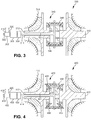
- FIG. 3 schematically illustrates a turbocharger 300 for use with an internal combustion engine 302 according to another example.
- the example shown in FIG. 3 includes similar components to the turbocharger 200 for use with the internal combustion engine 202 illustrated in FIG. 2 . Similar features of the example shown in FIG. 3 are numbered similarly in series, with the exception of the features described below.
- FIG. 3 schematically illustrates the turbocharger 300 for use with an internal combustion engine 302.
- the turbocharger 300 is in driving engagement and fluid communication with the internal combustion engine 302.
- the turbocharger 300 is in driving engagement with the internal combustion engine 302 through a differential device 340, a ratio adjusting device 306, and an infinitely variable transmission 308.
- the internal combustion engine 302 is used as a power source for a vehicle (not shown); however, it is understood that the internal combustion engine 302 may be used in other applications, such as in stationary power generation applications.
- the differential device 340 comprises a first side gear 342, a second side gear 344, a differential carrier 346, and a plurality of spider gears 348.
- the first side gear 342, the second side gear 344, the differential carrier 346, and the plurality of spider gears 348 are disposed within the housing 316, between the turbine portion 310 and the compressor portion 312.
- the first side gear 342 and the second side gear 344 are magnetic bevel gears respectively disposed on and spliningly engaged with the compressor portion 312 and the turbine portion 310.
- Each of the side gears 342, 344 comprise a plurality of magnets arranged in a circular pattern in a face of the side gears 342, 344. A polarity of alternating magnets is reversed for magnetically engaging each of the plurality of spider gears 348.
- the first side gear 342 and the second side gear 344 may be integrally formed with the compressor portion 312 and the turbine portion 310, respectively.
- the differential carrier 346 is a member in driving engagement with the output shaft 314 on which the plurality of spider gears 348 are rotatingly disposed.
- the plurality of spider gears 348 are magnetic bevel gears each in magnetic engagement with the first side gear 342 and the second side gear 344 and facilitate a differential action therebetween.
- Each of the spider gears 348 comprise a plurality of magnets arranged in a circular pattern in a face of the gears 348. A polarity of alternating magnets is reversed for magnetically engaging each of the side gears 342, 344.
- FIG. 3 illustrates the differential device 340 having two spider gears 328; however, it is understood that the differential device 340 may include three or more spider gears 348.
- FIG. 4 schematically illustrates a turbocharger 400 for use with an internal combustion engine 402 according to another example.
- the example shown in FIG. 4 includes similar components to the turbocharger 200 for use with the internal combustion engine 202 illustrated in FIG. 2 . Similar features of the example shown in FIG. 4 are numbered similarly in series, with the exception of the features described below.
- FIG. 4 schematically illustrates the turbocharger 400 for use with an internal combustion engine 402.
- the turbocharger 400 is in driving engagement and fluid communication with the internal combustion engine 402.
- the turbocharger 400 is in driving engagement with the internal combustion engine 402 through a differential device 450, a ratio adjusting device 406, and an infinitely variable transmission 408.
- the internal combustion engine 402 is used as a power source for a vehicle (not shown); however, it is understood that the internal combustion engine 402 may be used in other applications, such as in stationary power generation applications.
- the differential device 450 comprises a first side gear 452, a second side gear 454, a first intermediate ferrite member 455, a second intermediate ferrite member 456, a differential carrier 457, and a plurality of spider gears 458.
- the first side gear 452, the second side gear 454, the first intermediate ferrite member 455, the second intermediate ferrite member 456, the differential carrier 457, and the plurality of spider gears 458 are disposed within the housing 416, between the turbine portion 410 and the compressor portion 412.
- the differential carrier 457 is a member in driving engagement with the output shaft 414 on which the plurality of spider gears 458 are rotatingly disposed.
- FIG. 5 schematically illustrates a turbocharger 500 for use with an internal combustion engine 502 according to another example.
- the example shown in FIG. 5 includes similar components to the turbocharger 200 for use with the internal combustion engine 202 illustrated in FIG. 2 . Similar features of the example shown in FIG. 5 are numbered similarly in series, with the exception of the features described below.
- the first drive ring 562 is an annular member formed from a metal.
- the first drive ring 562 is disposed on and spliningly engaged with the compressor portion 512.
- a portion of an outer surface of the first drive ring 562 is configured to contact a portion of each of the plurality of balls 568.
- the portion of each of the plurality of balls 568 is in driving engagement with the first drive ring 562 through one of a boundary layer type friction and an elastohydrodynamic film.
- Such driving engagement affords a transfer of torque without slipping.
- At least a portion of the housing 516 is filled with a shear thickening fluid to facilitate the driving engagement with the first drive ring 562 and the plurality of balls 568.
- the second drive ring 564 is an annular member formed from a metal.
- the second drive ring 564 is disposed on and spliningly engaged with the turbine portion 510.
- a portion of an outer surface of the second drive ring 564 is configured to contact a portion of each of the plurality of balls 568.
- the portion of each of the plurality of balls 568 is in driving engagement with the second drive ring 564 through one of a boundary layer type friction and an elastohydrodynamic film.
- at least a portion of the housing 516 is filled with the shear thickening fluid to facilitate the driving engagement with the second drive ring 564 and the plurality of balls 568.
- the ball carrier 566 is a member in driving engagement with the output shaft 514.
- the ball carrier includes a plurality of axes 569 in a radially arrangement onto which the plurality of balls 568 are rotatingly disposed.
- FIG. 6 schematically illustrates a turbocharger 600 for use with an internal combustion engine 602 according to another example.
- the example shown in FIG. 6 includes similar components to the turbocharger 200 for use with the internal combustion engine 202 illustrated in FIG. 2 . Similar features of the example shown in FIG. 6 are numbered similarly in series, with the exception of the features described below.
- FIG. 6 schematically illustrates the turbocharger 600 for use with an internal combustion engine 602.
- the turbocharger 600 is in driving engagement and fluid communication with the internal combustion engine 602.
- the turbocharger 600 is in driving engagement with the internal combustion engine 602 through a differential device 670, a ratio adjusting device 606, and an infinitely variable transmission 608.
- the internal combustion engine 602 is used as a power source for a vehicle (not shown); however, it is understood that the internal combustion engine 602 may be used in other applications, such as in stationary power generation applications.
- the turbocharger 600 includes a turbine portion 610, a compressor portion 612, the differential device 670, an output gear 613, and an output shaft 615.
- the turbine portion 610, the compressor portion 612, the differential device 670, the output gear 613, and the output shaft 615 are rotatably mounted within a housing 616 using a plurality of bearings (not shown).
- the turbine portion 610 and the compressor portion 612 are drivingly engaged with the output shaft 615 through the differential device 670 and the output gear 613.
- the turbine portion 610 is driven by exhaust gases via an exhaust port 618 of the internal combustion engine 602.
- the turbine portion 610 is drivingly engaged with the compressor portion 612 through the differential device 670 to provide compressed air to an intake port 620 of the internal combustion engine 602.
- the output shaft 615 is also drivingly engaged with the internal combustion engine 602 through the ratio adjusting device 606 and the infinitely variable transmission 608; however, it is understood that the turbine portion 610 and the compressor portion 612 may be drivingly engaged with the internal combustion engine 602 in another manner that facilitates infinitely variable driving engagement therebetween.
- the differential device 670 comprises a first side gear 672, a second side gear 674, a differential carrier 676, a plurality of spider gears 677, and a differential housing 678.
- the first side gear 672, the second side gear 674, the differential carrier 676, and the plurality of spider gears 677 are disposed within the differential housing 678, which is rotatably disposed between the turbine portion 610 and the compressor portion 612.
- the first side gear 672 and the second side gear 674 are bevel gears respectively disposed on and spliningly engaged with the compressor portion 612 and the turbine portion 610.
- the first side gear 672 and the second side gear 674 may be integrally formed with the compressor portion 612 and the turbine portion 610, respectively.
- the differential housing 678 is a hollow member into which the first side gear 672, the second side gear 674, the differential carrier 676, and the plurality of spider gears 677 are disposed.
- An outer surface of the differential housing 678 includes a ring gear 679 coupled thereto. Alternately, it is understood that the ring gear 679 may be integrally formed with the differential housing 678.
- the ring gear 679 is in driving engagement with the output gear 613.
- the output gear 613 is drivingly engaged with the ring gear 679 and the output shaft 615.
- the output gear 613 is rotatably disposed in the housing 616 and supported by bearings (not shown).
- the output shaft 615 is a member drivingly engaged with the internal combustion engine 602 and the output gear 613.
- the output shaft 615 is drivingly engaged with the internal combustion engine 602 through the ratio adjusting device 606 and the infinitely variable transmission 608.
- FIG. 7 schematically illustrates the turbocharger 700 for use with an internal combustion engine 702.
- the turbocharger 700 is in driving engagement and fluid communication with the internal combustion engine 702.
- the turbocharger 700 is in driving engagement with the internal combustion engine 702 through a differential device 780, a ratio adjusting device 706, and an infinitely variable transmission 708.
- the internal combustion engine 702 is used as a power source for a vehicle (not shown); however, it is understood that the internal combustion engine 702 may be used in other applications, such as in stationary power generation applications.
- the turbocharger 700 includes a turbine portion 782, a compressor portion 784, the differential device 780, an output gear 713, and an output shaft 715.
- the turbine portion 782, the compressor portion 784, the differential device 780, the output gear 713, and the output shaft 715 are rotatably mounted within a housing 716 using a plurality of bearings (not shown).
- the output shaft 715 is also drivingly engaged with the internal combustion engine 702 through the ratio adjusting device 706 and the infinitely variable transmission 708; however, it is understood that the turbine portion 782 and the compressor portion 784 may be drivingly engaged internal combustion engine 702 in another manner that facilitates infinitely variable driving engagement therebetween.
- the differential device 780 comprises a first side gear 787, a second side gear 788, a differential carrier 789, a plurality of spider gears 790, a pair of intermediate ferrous members 791, and a differential housing 792.
- the first side gear 787, the second side gear 788, the differential carrier 789, and the plurality of spider gears 790 are disposed within the differential housing 792, which is rotatably disposed between the turbine portion 782 and the compressor portion 784.
- Each of intermediate ferrous members 791 is fixed with respect to the housing 716 and each is disposed between the first side gear 787 and the compressor portion 784 and the second side gear 788 and the turbine portion 782, respectively.
- the first side gear 787 and the second side gear 788 are bevel gears respectively disposed adjacent to and in magnetic driving engagement with the compressor portion 784 and the turbine portion 782.
- the first side gear 787 includes a third magnetic array 793 to facilitate driving engagement with the compressor portion 784.
- the third magnetic array 793 is cylindrical in shape and is disposed about the second magnetic array 786 of the compressor portion 784.
- the second side gear 788 includes a fourth magnetic array 794 to facilitate driving engagement with the turbine portion 782.
- the fourth magnetic array 795 is cylindrical in shape and is disposed about the first magnetic array 785 of the turbine portion 782.
- the third magnetic array 793, one of the intermediate ferrous members 791, and the second magnetic array 786 form a magnetic drive ratio adjusting device, which is used to adjust a drive ratio between the compressor portion 784 and the first side gear 787.
- the magnetic drive ratio adjusting device is used to cause a speed reduction between the compressor portion 784 and the first side gear 787. It is understood that other magnetic arrangements may be used to cause a speed reduction between the compressor portion 784 and the first side gear 787.
- the fourth magnetic array 795, one of the intermediate ferrous members 791, and the first magnetic array 785 form a magnetic drive ratio adjusting device, which is used to adjust a drive ratio between the turbine portion 782 and the second side gear 788.
- the magnetic drive ratio adjusting device is used to cause a speed reduction between the turbine portion 782 and the second side gear 788. It is understood that other magnetic arrangements may be used to cause a speed reduction between the turbine portion 782 and the second side gear 788. Further, it is understood that the principles of the magnetic drive ratio adjusting device may be applied to any of the examples described hereinabove.
- the differential carrier 789 is a member in driving engagement with the differential housing 792.
- the plurality of spider gears 790 is rotatingly disposed on the differential carrier 789.
- the plurality of spider gears 790 are bevel gears each in driving engagement with the first side gear 787 and the second side gear 788 and facilitate a differential action therebetween.
- FIG. 7 illustrates the differential device 780 having two spider gears 790; however, it is understood that the differential device 780 may include three or more spider gears 790.
- the differential housing 792 is a hollow member into which the first side gear 787, the second side gear 788, the differential carrier 789, and the plurality of spider gears 790 are disposed.
- An outer surface of the differential housing 792 includes a ring gear 795 coupled thereto.
- the ring gear 795 may be integrally formed with the differential housing 792.
- the ring gear 795 is in driving engagement with the output gear 713.
- the output gear 713 is drivingly engaged with the ring gear 795 and the output shaft 715.
- the output gear 713 is rotatably disposed in the housing 716 and supported by bearings (not shown).
- the output shaft 715 is a member drivingly engaged with the internal combustion engine 702 and the output gear 713.
- the output shaft 715 is drivingly engaged with the internal combustion engine 702 through the ratio adjusting device 706 and the infinitely variable transmission 708.
- the manner of providing driving engagement between the internal combustion engine 602, 702 and the differential device 670, 780 may be adapted to provide driving engagement between the internal combustion engine 202, 302, 402, 502 and the differential device 204, 340, 450, 560.
- the turbocharger 200, 300, 400, 500, 600, 700 is drivingly engaged with the internal combustion engine 202, 302, 402, 502, 602, 702 through the infinitely variable transmission 208, 308, 408, 508, 608, 708 for at least two purposes: a first purpose is to allow the compressor portion 212, 312, 412, 512, 612, 784 to be at least partially driven by the internal combustion engine 202, 302, 402, 502, 602, 702; a second purpose is to allow the turbine portion 210, 310, 410, 510, 610, 782 to be drivingly engaged with the internal combustion engine 202, 302, 402, 502, 602, 702, or an output (not shown) thereof, through the infinitely variable transmission 208, 308, 408, 508, 608, 708.
- differential device 204, 340, 450, 560, 670, 780 allow for the turbine portion 210, 310, 410, 510, 610, 782 and the compressor portion 212, 312, 412, 512, 612, 784 to rotate at different speeds, which increases a performance of the turbocharger 200, 300, 400, 500, 600, 700.
- FIG. 8 illustrates an exemplary speed diagram of the compressor portion 212, 312, 412, 512, 612, 784, the carrier 226, 346, 457, 566, 676, 789, and the turbine portion 210, 310, 410, 510, 610, 782 of the differential device 204, 340, 450, 560, 670, 780 during three different modes of operation of the turbocharger 200, 300, 400, 500, 600, 700.
- a control system in communication with the infinitely variable transmission 208, 308, 408, 508, 608, 708 is used to control a rotational speed of the carrier 226, 346, 457, 566, 676, 789 (and thus a rotational speed of the compressor portion 212, 312, 412, 512, 612, 784.
- the control system may adjust the infinitely variable transmission 208, 308, 408, 508, 608, 708 based on at least one of a driver action, a speed of a vehicle the turbocharger 200, 300, 400, 500, 600, 700 is incorporated in, a rotational speed of the compressor portion 212, 312, 412, 512, 612, 784, and a rotational speed of the turbine portion 210, 310, 410, 510, 610, 782.
- the driver action may a throttle adjustment.
- the three horizontal axes of FIG. 8 represent respectively, from top to bottom, a rotation speed of the compressor portion 212, 312, 412, 512, 612, 784 (and the side gear 222, 342, 452, 672, 787 or the drive ring 562), a rotation speed of the carrier 226, 346, 457, 566, 676, 789, and a rotation speed of the turbine portion 210, 310, 410, 510, 610, 782 (and the side gear 224, 344, 454, 674, 788 or the drive ring 564).
- the rotation speed of the turbine portion 210, 310, 410, 510, 610, 782 is determined by the exhaust gases flowing through the turbine portion 210, 310, 410, 510, 610, 782.
- the rotational speed of the compressor portion 212, 312, 412, 512, 612, 784 may be varied while keeping the rotational speed of the turbine portion 210, 310, 410, 510, 610, 782 substantially constant.
- a first mode of operation of the turbocharger 200, 300, 400, 500, 600, 700 is represented on the speed diagram at point A.
- the rotational speed of the carrier 226, 346, 457, 566, 676, 789 is substantially equal to zero, which is indicative that a ratio of the infinitely variable transmission 208, 308, 408, 508, 608, 708 is substantially equal to zero.
- the compressor portion 212, 312, 412, 512, 612, 784 is rotating at the same speed as the turbine portion 210, 310, 410, 510, 610, 782, but in an opposite direction.
- energy coming from the turbine portion 210, 310, 410, 510, 610, 782 is entirely applied to the compressor portion 212, 312, 412, 512, 612, 784, only with an opposite direction of rotation.
- a second mode of operation of the turbocharger 200, 300, 400, 500, 600, 700 is represented on the speed diagram by a range of speeds at B.
- the rotational speed of the carrier 226, 346, 457, 566, 676, 789 is a negative value (with respect to the turbine portion 210, 310, 410, 510, 610, 782).
- energy is applied from the internal combustion engine 202, 302, 402, 502, 602, 702 to accelerate the compressor portion 212, 312, 412, 512, 612, 784 and to provide additional boost.
- Energy applied from the internal combustion engine 202, 302, 402, 502, 602, 702 reduces a turbo lag of the turbocharger 200, 300, 400, 500, 600, 700.
- Energy applied from the internal combustion engine 202, 302, 402, 502, 602, 702 is in addition to energy applied by the turbine portion 210, 310, 410, 510, 610, 782.
- the rotational speed of the carrier 226, 346, 457, 566, 676, 789 is the product of the speed of the internal combustion engine 202, 302, 402, 502, 602, 702, a ratio employed by the infinitely variable transmission 208, 308, 408, 508, 608, 708, and a ratio employed by the ratio adjusting device 206, 306, 406, 506, 606, 706. It is understood that each of the aforementioned ratios may be determined in order to increase an effectiveness of the turbocharger 200, 300, 400, 500, 600, 700.
- a third mode of operation of the turbocharger 200, 300, 400, 500, 600, 700 is represented on the speed diagram by a range of speeds at C.
- the rotational speed of the carrier 226, 346, 457, 566, 676, 789 is a positive value (with respect to the turbine portion 210, 310, 410, 510, 610, 782).
- energy is applied from the turbine portion 210, 310, 410, 510, 610, 782 to the internal combustion engine 202, 302, 402, 502, 602, 702.
- the amount of energy applied from the turbine portion 210, 310, 410, 510, 610, 782 is a surplus amount of energy not required by the compressor portion 212, 312, 412, 512, 612, 784.
- substantially all or a very large percentage of energy from the turbine portion 210, 310, 410, 510, 610, 782 is applied to the carrier 226, 346, 457, 566, 676, 789, the ratio adjusting device 206, 306, 406, 506, 606, 706, the infinitely variable transmission 208, 308, 408, 508, 608, 708, and the internal combustion engine 202, 302, 402, 502, 602, 702.
- the third mode of operation allows energy to be recuperated and to be applied to the internal combustion engine 202, 302, 402, 502, 602, 702, or the output thereof.
- the rotational speed of the carrier 226, 346, 457, 566, 676, 789 is the product of the speed of the internal combustion engine 202, 302, 402, 502, 602, 702, a ratio employed by the infinitely variable transmission 208, 308, 408, 508, 608, 708, and a ratio employed by the ratio adjusting device 206, 306, 406, 506, 606, 706. It is understood that each of the aforementioned ratios may be determined in order to increase an effectiveness of the turbocharger 200, 300, 400, 500, 600, 700.
- the turbocharger 200, 300, 400, 500, 600, 700 also prevents a maximum boost pressure from being exceeded by being able to direct at least a portion of the energy recuperated in the turbine portion 210, 310, 410, 510, 610, 782 to the internal combustion engine 202, 302, 402, 502, 602, 702. Further, the turbocharger 200, 300, 400, 500, 600, 700 is able to adapt a speed of the compressor portion 212, 312, 412, 512, 612, 784 to achieve a required compression by adjusting a ratio of the infinitely variable transmission 208, 308, 408, 508, 608, 708.
Landscapes
- Engineering & Computer Science (AREA)
- General Engineering & Computer Science (AREA)
- Mechanical Engineering (AREA)
- Chemical & Material Sciences (AREA)
- Combustion & Propulsion (AREA)
- Software Systems (AREA)
- Theoretical Computer Science (AREA)
- Power Engineering (AREA)
- General Chemical & Material Sciences (AREA)
- Chemical Kinetics & Catalysis (AREA)
- Computer Security & Cryptography (AREA)
- General Physics & Mathematics (AREA)
- Physics & Mathematics (AREA)
- Supercharger (AREA)
- Information Transfer Between Computers (AREA)
Description
- The present invention relates to energy recovery systems and more specifically to waste heat recovery systems used with internal combustions engines.
- In conventional reciprocating piston engines, ambient air is typically pulled inside an engine cylinder during an intake (or induction) stroke of a piston. The volumetric efficiency, which is the amount of air inducted into the engine cylinder by the piston divided by the cylinder volume, is limited both by the atmospheric pressure and the change in pressure needed to bring air into the cylinder. Increasing the volumetric efficiency reduces relative engine losses, increases engine efficiency, and also increase the power output of the engine without increasing a displacement of the engine. A related common trend is engine downsizing, which means a size of the engine is reduced in order to decrease engine losses significantly, while maintaining about the same amount of power output from the engine.
- In order to improve the volumetric efficiency of naturally aspirated engines, two forced induction devices may be typically used; a turbocharger or a supercharger. A supercharger typically comprises a compressor in driving engagement with an engine crankshaft to compress additional air before intake into the engine. Superchargers will not be discussed in detail herein as they do not recuperate the kinetic energy from an exhaust gas flow; instead superchargers increase the power of the engine by increasing the volumetric efficiency of the engine.
-
FIG. 1 shows a cut-through sketch of a turbocharger 100 known in the prior art. Aturbine 102, which is a radial inflow turbine expander, is shown which has anintake port 104 where the exhaust gas flow enters theturbine 102 radially and leaves through anoutlet port 106 axially. A plurality ofblades 108 of theturbine 102 allow for a recuperation of kinetic energy from the exhaust gas flow, which is directed to acentral rotor hub 110. Thecentral rotor hub 110 is also drivingly engaged with acompressor 112, in which a flow of air enters anintake port 114 axially and is pushed radially to anoutlet port 116 by a plurality ofblades 118 of thecompressor 112. Due to inherent limitations in the design, the turbocharger 100 is subject to several issues that may be solved by using a complex control methodology or through the addition of costly technologies to the turbocharger 100. - One issue associated with such a turbocharger is a maximum boost pressure that the engine can withstand without damage to components of the engine due to increased pressure. Further, knocking of the engine may damage the turbocharger. A boost pressure increases depending on am amount of exhaust gases, as the compressor is directly linked to the turbine. At a certain point, pressure has to be limited to avoid engine knocking and other potential damage related to the increased pressure at an intake manifold of the engine. This issue is commonly corrected through the use of a wastegate. The wastegate diverts a portion of the exhaust gas from the turbine, thus limiting the pressure and amount of energy that can be recuperated by the turbine. In a conventional configuration of a turbocharger, the excessive wasted exhaust and the complex control of the wastegate cannot be avoided.
- Another issue associated with such a turbocharger issue is a dynamic known as turbo lag. Turbo lag is a time required to adjust a power output of the turbocharger in response to an adjustment in a throttle of the vehicle. Turbo lag is caused by an amount of time needed to generate a required pressure boost by an exhaust system and the turbine. Turbo lag significantly depends on the inertia of the components of the turbocharger, an amount of friction within the turbocharger, and an initial speed of the turbocharger, and an amount of exhaust gas passing through the turbine. A number of ways exist to decrease the turbo lag. For example, it is possible to decrease the rotational inertia, to change the aspect ratio of the turbine, to use variable geometry components, amongst other improvement, but all improvements significantly affect a cost and complexity of the turbocharger.
- Another issue associated with such a turbocharger is a boost threshold. Turbochargers start producing boost only when enough energy can be recuperated by the turbine. Without the required amount of kinetic energy, the turbocharger will not be able to provide the required amount of boost. An engine speed at which this limitation disappears is called a boost threshold speed. The boost threshold speed is dependent on an engine size and an operating speed of the engine, a throttle opening, and a design of the turbocharger. As a result of the boot threshold, an operator of a vehicle including the turbocharger may notice an ineffectiveness of the turbocharger when the engine is operated under a certain speed.
- A final issue associated with such a turbocharger is based on an energy recuperation capability of the turbocharger. The turbine of the turbocharger is only able to recuperate energy from the exhaust gas flow to compress intake gases. If the operator of the vehicle requests a low amount of power output from the engine, compression of the intake gases is not necessary, and all of the kinetic energy in the exhaust gas flow is directed around the turbine using the wastegate. Directing the exhaust gas flow around the turbine using the wastegate is an inefficient manner of operation for the turbocharger.
-
DE 12 37 380 B discloses a turbocharger for use with an internal combustion engine. The turbocharger comprises: a differential device having a carrier, a compressor in driving engagement with a first side gear of the differential device, and a turbine in driving engagement with a second side gear of the differential device, wherein the carrier of the differential device is in driving engagement with an infinitely variable transmission and the infinitely variable transmission is in driving engagement with the internal combustion engine. - It is an object of the present invention to develop a turbocharger for an internal combustion engine that is simply controlled, reduces turbo lag, decreases a boost threshold of the turbocharger, and increases an efficiency of the internal combustion engine.
- According to the invention, this object is solved by a turbocharger comprising the features of claim 1. Preferred embodiments of this turbocharger are defined in the dependent claims.
- Various aspects of this invention will become apparent to those skilled in the art from the following detailed description of the preferred embodiment, when read in light of the accompanying drawings.
- The above, as well as other advantages of the present invention will become readily apparent to those skilled in the art from the following detailed description when considered in the light of the accompanying drawings in which:
-
FIG. 1 is a schematic illustration of a cut away side view of a turbocharger known in the prior art; -
FIG. 2 is a schematic illustration of a cut away side view of an example of a turbocharger not covered by the present invention but useful for understanding the invention, wherein the turbocharger is in driving engagement with a ratio adjusting device, an infinitely variable transmission, and an internal combustion engine; -
FIG. 3 is a schematic illustration of a cut away side view of another example of a turbocharger not covered by the present invention but useful for understanding the invention, wherein the turbocharger is in driving engagement with a ratio adjusting device, an infinitely variable transmission, and an internal combustion engine; -
FIG. 4 is a schematic illustration of a cut away side view of another example of a turbocharger not covered by the present invention but useful for understanding the invention, wherein the turbocharger is in driving engagement with a ratio adjusting device, an infinitely variable transmission, and an internal combustion engine; -
FIG. 5 is a schematic illustration of a cut away side view of another example of a turbocharger not covered by the present invention but useful for understanding the invention, wherein, the turbocharger is in driving engagement with a ratio adjusting device, an infinitely variable transmission, and an internal combustion engine; -
FIG. 6 is a schematic illustration of a cut away side view of another example of a turbocharger not covered by the present invention but useful for understanding the invention, wherein the turbocharger is in driving engagement with a ratio adjusting device, an infinitely variable transmission, and an internal combustion engine; -
FIG. 7 is a schematic illustration of a cut away side view of a turbocharger according to an embodiment of the present invention, wherein the turbocharger is in driving engagement with a ratio adjusting device, an infinitely variable transmission, and an internal combustion engine; and -
FIG. 8 is a speed diagram of the turbocharger according to the embodiment of the present invention. - It is to be understood that the invention may assume various alternative orientations and step sequences, except where expressly specified to the contrary. It is also to be understood that the specific devices and processes illustrated in
FIGS. 7 and 8 , and described in the following specification are simply exemplary embodiments of the inventive concepts defined herein. Hence, specific dimensions, directions or other physical characteristics relating to this embodiment are not to be considered as limiting, unless expressly stated otherwise. -
FIG. 2 schematically illustrates aturbocharger 200 for use with aninternal combustion engine 202. Theturbocharger 200 is in driving engagement and fluid communication with theinternal combustion engine 202. Theturbocharger 200 is in driving engagement with theinternal combustion engine 202 through adifferential device 204, a ratio adjustingdevice 206, and an infinitelyvariable transmission 208. Typically, theinternal combustion engine 202 is used as a power source for a vehicle (not shown); however, it is understood that theinternal combustion engine 202 may be used in other applications, such as in stationary power generation applications. - The
turbocharger 200 includes aturbine portion 210, acompressor portion 212, thedifferential device 204, and anoutput shaft 214. Theturbine portion 210, thecompressor portion 212, thedifferential device 204, and theoutput shaft 214 are rotatably mounted within ahousing 216 using a plurality of bearings (not shown). Theturbine portion 210 and thecompressor portion 212 are drivingly engaged with theoutput shaft 214 through thedifferential device 204. As is known in the art, theturbine portion 210 is driven by exhaust gases via anexhaust port 218 of theinternal combustion engine 202. Theturbine portion 210 is drivingly engaged with thecompressor portion 212 through thedifferential device 204 to provide compressed air to anintake port 220 of theinternal combustion engine 202. Theoutput shaft 214 is also drivingly engaged with theinternal combustion engine 202 through theratio adjusting device 206 and the infinitelyvariable transmission 208; however, it is understood that theturbine portion 210 and thecompressor portion 212 may be drivingly engagedinternal combustion engine 202 in another manner that facilitates infinitely variable driving engagement therebetween. As shown inFIG. 2 , theoutput shaft 214 passes through acentral perforation 221 formed through thecompressor portion 212; however, it is understood that theoutput shaft 214 may pass through theturbine portion 210 or that theoutput shaft 214 may be drivingly engaged with theinternal combustion engine 202 in another manner. - The
differential device 204 comprises a first side gear 222, asecond side gear 224, adifferential carrier 226, and a plurality of spider gears 228. The first side gear 222, thesecond side gear 224, thedifferential carrier 226, and the plurality of spider gears 228 are disposed within thehousing 216, between theturbine portion 210 and thecompressor portion 212. The first side gear 222 and thesecond side gear 224 are bevel gears respectively disposed on and spliningly engaged with thecompressor portion 212 and theturbine portion 210. Alternately, it is understood that the first side gear 222 and thesecond side gear 224 may be integrally formed with thecompressor portion 212 and theturbine portion 210, respectively. Thedifferential carrier 226 is a member in driving engagement with theoutput shaft 214 on which the plurality of spider gears 228 are rotatingly disposed. The plurality of spider gears 228 are bevel gears each in driving engagement with the first side gear 222 and thesecond side gear 224 and facilitate a differential action therebetween.FIG. 2 illustrates thedifferential device 204 having two spider gears 228; however, it is understood that thedifferential device 204 may include three or more spider gears 228. It is also understood that theturbocharger 200 can be adapted to include a planetary style differential, instead of the bevel gear style differential shown inFIG. 2 . - The
internal combustion engine 202 comprises at least an engine block (not shown) and anengine output 232; however, it is understood that theinternal combustion engine 202 will typically include other components, such as a plurality of valves, a plurality of pistons, at least one crankshaft, a plurality of connecting rods, a clutching device, a fuel delivery system, an ignition system, and a cooling system. Theinternal combustion engine 202 is in fluid communication with theturbocharger 200 through theintake port 220 and theexhaust port 218. Theinternal combustion engine 202 is in driving engagement with theoutput shaft 214 through the infinitelyvariable transmission 208 and theratio adjusting device 206. Theinternal combustion engine 202 may be any type of internal combustion engine which may be fitted with a turbocharger. - The
ratio adjusting device 206 is a drive ratio adjusting device in driving engagement with theoutput shaft 214 and the infinitelyvariable transmission 208. Theratio adjusting device 206 is a fixed ratio device which adjusts a drive ratio between theoutput shaft 214 and the infinitelyvariable transmission 208. As a non-limiting example, theratio adjusting device 206 may comprise a plurality of gears drivingly engaged with one another.FIG. 2 illustrates theratio adjusting device 206 disposed about a portion of theoutput shaft 214; however, it is understood that theratio adjusting device 206 may be arranged in another manner, such as through a gear, a belt, or a power take off, for example. - The infinitely
variable transmission 208 is a drive ratio adjusting device that is in driving engagement with theratio adjusting device 206 and theinternal combustion engine 202. The infinitelyvariable transmission 208 may be placed in an infinite number of drive ratios to facilitate driving engagement between theratio adjusting device 206 and theinternal combustion engine 202. It is understood that the infinitelyvariable transmission 208 may be placed in a positive drive ratio, a negative drive ratio, and a zero drive ratio. The infinitelyvariable transmission 208 may include a clutching device (not shown) for drivingly disengaging theinternal combustion engine 202 from theturbocharger 200. As a non-limiting example, the infinitelyvariable transmission 208 may be a tilting ball style infinitely variable transmission or another type of infinitely variable transmission.FIG. 2 illustrates the infinitelyvariable transmission 208 disposed about a portion of theoutput shaft 214; however, it is understood that the infinitelyvariable transmission 208 may be arranged in another manner, such as through a gear, a belt, or a power take off, for example. It is also understood that the infinitelyvariable transmission 208 can be substituted with an electric motor (not shown), the electric motor in electrical communication with a control system (not shown) of a vehicle incorporating theturbocharger 200. -
FIG. 3 schematically illustrates aturbocharger 300 for use with aninternal combustion engine 302 according to another example. The example shown inFIG. 3 includes similar components to theturbocharger 200 for use with theinternal combustion engine 202 illustrated inFIG. 2 . Similar features of the example shown inFIG. 3 are numbered similarly in series, with the exception of the features described below. -
FIG. 3 schematically illustrates theturbocharger 300 for use with aninternal combustion engine 302. Theturbocharger 300 is in driving engagement and fluid communication with theinternal combustion engine 302. Theturbocharger 300 is in driving engagement with theinternal combustion engine 302 through adifferential device 340, aratio adjusting device 306, and an infinitelyvariable transmission 308. Typically, theinternal combustion engine 302 is used as a power source for a vehicle (not shown); however, it is understood that theinternal combustion engine 302 may be used in other applications, such as in stationary power generation applications. - The
differential device 340 comprises afirst side gear 342, asecond side gear 344, adifferential carrier 346, and a plurality of spider gears 348. Thefirst side gear 342, thesecond side gear 344, thedifferential carrier 346, and the plurality of spider gears 348 are disposed within thehousing 316, between theturbine portion 310 and thecompressor portion 312. - The
first side gear 342 and thesecond side gear 344 are magnetic bevel gears respectively disposed on and spliningly engaged with thecompressor portion 312 and theturbine portion 310. Each of the side gears 342, 344 comprise a plurality of magnets arranged in a circular pattern in a face of the side gears 342, 344. A polarity of alternating magnets is reversed for magnetically engaging each of the plurality of spider gears 348. Alternately, it is understood that thefirst side gear 342 and thesecond side gear 344 may be integrally formed with thecompressor portion 312 and theturbine portion 310, respectively. - The
differential carrier 346 is a member in driving engagement with theoutput shaft 314 on which the plurality of spider gears 348 are rotatingly disposed. - The plurality of spider gears 348 are magnetic bevel gears each in magnetic engagement with the
first side gear 342 and thesecond side gear 344 and facilitate a differential action therebetween. Each of the spider gears 348 comprise a plurality of magnets arranged in a circular pattern in a face of thegears 348. A polarity of alternating magnets is reversed for magnetically engaging each of the side gears 342, 344.FIG. 3 illustrates thedifferential device 340 having two spider gears 328; however, it is understood that thedifferential device 340 may include three or more spider gears 348. -
FIG. 4 schematically illustrates aturbocharger 400 for use with aninternal combustion engine 402 according to another example. The example shown inFIG. 4 includes similar components to theturbocharger 200 for use with theinternal combustion engine 202 illustrated inFIG. 2 . Similar features of the example shown inFIG. 4 are numbered similarly in series, with the exception of the features described below. -
FIG. 4 schematically illustrates theturbocharger 400 for use with aninternal combustion engine 402. Theturbocharger 400 is in driving engagement and fluid communication with theinternal combustion engine 402. Theturbocharger 400 is in driving engagement with theinternal combustion engine 402 through adifferential device 450, aratio adjusting device 406, and an infinitelyvariable transmission 408. Typically, theinternal combustion engine 402 is used as a power source for a vehicle (not shown); however, it is understood that theinternal combustion engine 402 may be used in other applications, such as in stationary power generation applications. - The
differential device 450 comprises afirst side gear 452, asecond side gear 454, a firstintermediate ferrite member 455, a secondintermediate ferrite member 456, adifferential carrier 457, and a plurality of spider gears 458. Thefirst side gear 452, thesecond side gear 454, the firstintermediate ferrite member 455, the secondintermediate ferrite member 456, thedifferential carrier 457, and the plurality of spider gears 458 are disposed within thehousing 416, between theturbine portion 410 and thecompressor portion 412. - The
first side gear 452 and thesecond side gear 454 are magnetic bevel gears respectively disposed on and spliningly engaged with thecompressor portion 412 and theturbine portion 410. Each of the side gears 452, 454 comprise a plurality of magnets arranged in a circular pattern in a face of the side gears 452, 454. A polarity of alternating magnets is reversed for magnetically engaging each of the plurality of spider gears 458 through theintermediate ferrite members first side gear 452 and thesecond side gear 454 may be integrally formed with thecompressor portion 412 and theturbine portion 410, respectively. - The first
intermediate ferrite member 455 is a member disposed between thefirst side gear 452 and the plurality of spider gears 458. The firstintermediate ferrite member 455 is formed from a ferrous material and facilitates in a transfer of the magnetic field between thefirst side gear 452 and the plurality of spider gears 458. - The second
intermediate ferrite member 456 is a member disposed between thesecond side gear 454 and the plurality of spider gears 458. The secondintermediate ferrite member 456 is formed from a ferrous material and facilitates in a transfer of the magnetic field between thesecond side gear 454 and the plurality of spider gears 458. - The
differential carrier 457 is a member in driving engagement with theoutput shaft 414 on which the plurality of spider gears 458 are rotatingly disposed. - The plurality of spider gears 458 are magnetic bevel gears each in magnetic engagement with the
first side gear 452 and thesecond side gear 454 through theintermediate ferrite members first side gear 452 and thesecond side gear 454. Each of the spider gears 458 comprise a plurality of magnets arranged in a circular pattern in a face of thegears 458. A polarity of alternating magnets is reversed for magnetically engaging each of the side gears 452, 454 through theintermediate ferrite members FIG. 4 illustrates thedifferential device 450 having two spider gears 458; however, it is understood that thedifferential device 450 may include three or more spider gears 458. -
FIG. 5 schematically illustrates aturbocharger 500 for use with aninternal combustion engine 502 according to another example. The example shown inFIG. 5 includes similar components to theturbocharger 200 for use with theinternal combustion engine 202 illustrated inFIG. 2 . Similar features of the example shown inFIG. 5 are numbered similarly in series, with the exception of the features described below. -
FIG. 5 schematically illustrates theturbocharger 500 for use with aninternal combustion engine 502. Theturbocharger 500 is in driving engagement and fluid communication with theinternal combustion engine 502. Theturbocharger 500 is in driving engagement with theinternal combustion engine 502 through adifferential device 560, aratio adjusting device 506, and an infinitelyvariable transmission 508. Typically, theinternal combustion engine 502 is used as a power source for a vehicle (not shown); however, it is understood that theinternal combustion engine 502 may be used in other applications, such as in stationary power generation applications. - The
differential device 560 comprises afirst drive ring 562, asecond drive ring 564, aball carrier 566, and a plurality ofballs 568. Thefirst drive ring 562, thesecond drive ring 564, theball carrier 566, and the plurality ofballs 568 are disposed within thehousing 516, between theturbine portion 510 and thecompressor portion 512. - The
first drive ring 562 is an annular member formed from a metal. Thefirst drive ring 562 is disposed on and spliningly engaged with thecompressor portion 512. A portion of an outer surface of thefirst drive ring 562 is configured to contact a portion of each of the plurality ofballs 568. The portion of each of the plurality ofballs 568 is in driving engagement with thefirst drive ring 562 through one of a boundary layer type friction and an elastohydrodynamic film. Such driving engagement affords a transfer of torque without slipping. At least a portion of thehousing 516 is filled with a shear thickening fluid to facilitate the driving engagement with thefirst drive ring 562 and the plurality ofballs 568. - The
second drive ring 564 is an annular member formed from a metal. Thesecond drive ring 564 is disposed on and spliningly engaged with theturbine portion 510. A portion of an outer surface of thesecond drive ring 564 is configured to contact a portion of each of the plurality ofballs 568. The portion of each of the plurality ofballs 568 is in driving engagement with thesecond drive ring 564 through one of a boundary layer type friction and an elastohydrodynamic film. As mentioned hereinabove, at least a portion of thehousing 516 is filled with the shear thickening fluid to facilitate the driving engagement with thesecond drive ring 564 and the plurality ofballs 568. - The
ball carrier 566 is a member in driving engagement with theoutput shaft 514. The ball carrier includes a plurality of axes 569 in a radially arrangement onto which the plurality ofballs 568 are rotatingly disposed. - The plurality of
balls 568 are metal spheres in driving engagement with thefirst drive ring 562 and thesecond drive ring 564 through the shear thickening fluid. The plurality ofballs 568 facilitates a differential action between thefirst drive ring 562 and thesecond drive ring 564, when theballs 568 rotate about the plurality of axes 569. Thedifferential device 560 may include three ormore balls 568. -
FIG. 6 schematically illustrates a turbocharger 600 for use with aninternal combustion engine 602 according to another example. The example shown inFIG. 6 includes similar components to theturbocharger 200 for use with theinternal combustion engine 202 illustrated inFIG. 2 . Similar features of the example shown inFIG. 6 are numbered similarly in series, with the exception of the features described below. -
FIG. 6 schematically illustrates the turbocharger 600 for use with aninternal combustion engine 602. The turbocharger 600 is in driving engagement and fluid communication with theinternal combustion engine 602. The turbocharger 600 is in driving engagement with theinternal combustion engine 602 through adifferential device 670, aratio adjusting device 606, and an infinitelyvariable transmission 608. Typically, theinternal combustion engine 602 is used as a power source for a vehicle (not shown); however, it is understood that theinternal combustion engine 602 may be used in other applications, such as in stationary power generation applications. - The turbocharger 600 includes a
turbine portion 610, acompressor portion 612, thedifferential device 670, anoutput gear 613, and anoutput shaft 615. Theturbine portion 610, thecompressor portion 612, thedifferential device 670, theoutput gear 613, and theoutput shaft 615 are rotatably mounted within ahousing 616 using a plurality of bearings (not shown). Theturbine portion 610 and thecompressor portion 612 are drivingly engaged with theoutput shaft 615 through thedifferential device 670 and theoutput gear 613. As is known in the art, theturbine portion 610 is driven by exhaust gases via an exhaust port 618 of theinternal combustion engine 602. Theturbine portion 610 is drivingly engaged with thecompressor portion 612 through thedifferential device 670 to provide compressed air to anintake port 620 of theinternal combustion engine 602. Theoutput shaft 615 is also drivingly engaged with theinternal combustion engine 602 through theratio adjusting device 606 and the infinitelyvariable transmission 608; however, it is understood that theturbine portion 610 and thecompressor portion 612 may be drivingly engaged with theinternal combustion engine 602 in another manner that facilitates infinitely variable driving engagement therebetween. - The
differential device 670 comprises afirst side gear 672, asecond side gear 674, adifferential carrier 676, a plurality of spider gears 677, and adifferential housing 678. Thefirst side gear 672, thesecond side gear 674, thedifferential carrier 676, and the plurality of spider gears 677 are disposed within thedifferential housing 678, which is rotatably disposed between theturbine portion 610 and thecompressor portion 612. Thefirst side gear 672 and thesecond side gear 674 are bevel gears respectively disposed on and spliningly engaged with thecompressor portion 612 and theturbine portion 610. Alternately, it is understood that thefirst side gear 672 and thesecond side gear 674 may be integrally formed with thecompressor portion 612 and theturbine portion 610, respectively. Thedifferential carrier 676 is a member in driving engagement with thedifferential housing 678. The plurality of spider gears 677 is rotatingly disposed on thedifferential carrier 676. The plurality of spider gears 677 are bevel gears each in driving engagement with thefirst side gear 672 and thesecond side gear 674 and facilitate a differential action therebetween.FIG. 6 illustrates thedifferential device 670 having two spider gears 677; however, it is understood that thedifferential device 670 may include three or more spider gears 677. - The
differential housing 678 is a hollow member into which thefirst side gear 672, thesecond side gear 674, thedifferential carrier 676, and the plurality of spider gears 677 are disposed. An outer surface of thedifferential housing 678 includes aring gear 679 coupled thereto. Alternately, it is understood that thering gear 679 may be integrally formed with thedifferential housing 678. Thering gear 679 is in driving engagement with theoutput gear 613. - The
output gear 613 is drivingly engaged with thering gear 679 and theoutput shaft 615. Theoutput gear 613 is rotatably disposed in thehousing 616 and supported by bearings (not shown). - The
output shaft 615 is a member drivingly engaged with theinternal combustion engine 602 and theoutput gear 613. Theoutput shaft 615 is drivingly engaged with theinternal combustion engine 602 through theratio adjusting device 606 and the infinitelyvariable transmission 608. -
FIG. 7 schematically illustrates aturbocharger 700 for use with aninternal combustion engine 702 according to an embodiment of the invention. The embodiment shown inFIG. 7 includes similar components to theturbocharger 200 for use with aninternal combustion engine 202 illustrated inFIG. 2 . Similar features of the embodiment shown inFIG. 7 are numbered similarly in series, with the exception of the features described below. -
FIG. 7 schematically illustrates theturbocharger 700 for use with aninternal combustion engine 702. Theturbocharger 700 is in driving engagement and fluid communication with theinternal combustion engine 702. Theturbocharger 700 is in driving engagement with theinternal combustion engine 702 through adifferential device 780, aratio adjusting device 706, and an infinitelyvariable transmission 708. Typically, theinternal combustion engine 702 is used as a power source for a vehicle (not shown); however, it is understood that theinternal combustion engine 702 may be used in other applications, such as in stationary power generation applications. - The
turbocharger 700 includes aturbine portion 782, acompressor portion 784, thedifferential device 780, anoutput gear 713, and anoutput shaft 715. Theturbine portion 782, thecompressor portion 784, thedifferential device 780, theoutput gear 713, and theoutput shaft 715 are rotatably mounted within a housing 716 using a plurality of bearings (not shown). Theoutput shaft 715 is also drivingly engaged with theinternal combustion engine 702 through theratio adjusting device 706 and the infinitelyvariable transmission 708; however, it is understood that theturbine portion 782 and thecompressor portion 784 may be drivingly engagedinternal combustion engine 702 in another manner that facilitates infinitely variable driving engagement therebetween. - The
turbine portion 782 and thecompressor portion 784 are drivingly engaged with theoutput shaft 715 through thedifferential device 780 and theoutput gear 713. As is known in the art, theturbine portion 782 is driven by exhaust gases via an exhaust port 718 of theinternal combustion engine 702. Theturbine portion 782 is drivingly engaged with thecompressor portion 784 through thedifferential device 780 to provide compressed air to an intake port 720 of theinternal combustion engine 702. Theturbine portion 782 includes a first magnetic array 785 to facilitate driving engagement with thedifferential device 780. As shown inFIG. 7 , the first magnetic array 785 is cylindrical in shape and is disposed within a portion of thedifferential device 780. Thecompressor portion 784 includes a secondmagnetic array 786 to facilitate driving engagement with thedifferential device 780. As shown inFIG. 7 , the secondmagnetic array 786 is cylindrical in shape and is disposed within a portion of thedifferential device 780. - The
differential device 780 comprises afirst side gear 787, a second side gear 788, adifferential carrier 789, a plurality of spider gears 790, a pair of intermediateferrous members 791, and adifferential housing 792. Thefirst side gear 787, the second side gear 788, thedifferential carrier 789, and the plurality of spider gears 790 are disposed within thedifferential housing 792, which is rotatably disposed between theturbine portion 782 and thecompressor portion 784. Each of intermediateferrous members 791 is fixed with respect to the housing 716 and each is disposed between thefirst side gear 787 and thecompressor portion 784 and the second side gear 788 and theturbine portion 782, respectively. Thefirst side gear 787 and the second side gear 788 are bevel gears respectively disposed adjacent to and in magnetic driving engagement with thecompressor portion 784 and theturbine portion 782. Thefirst side gear 787 includes a thirdmagnetic array 793 to facilitate driving engagement with thecompressor portion 784. As shown inFIG. 7 , the thirdmagnetic array 793 is cylindrical in shape and is disposed about the secondmagnetic array 786 of thecompressor portion 784. The second side gear 788 includes a fourthmagnetic array 794 to facilitate driving engagement with theturbine portion 782. As shown inFIG. 7 , the fourthmagnetic array 795 is cylindrical in shape and is disposed about the first magnetic array 785 of theturbine portion 782. - The third
magnetic array 793, one of the intermediateferrous members 791, and the secondmagnetic array 786 form a magnetic drive ratio adjusting device, which is used to adjust a drive ratio between thecompressor portion 784 and thefirst side gear 787. The magnetic drive ratio adjusting device is used to cause a speed reduction between thecompressor portion 784 and thefirst side gear 787. It is understood that other magnetic arrangements may be used to cause a speed reduction between thecompressor portion 784 and thefirst side gear 787. - The fourth
magnetic array 795, one of the intermediateferrous members 791, and the first magnetic array 785 form a magnetic drive ratio adjusting device, which is used to adjust a drive ratio between theturbine portion 782 and the second side gear 788. The magnetic drive ratio adjusting device is used to cause a speed reduction between theturbine portion 782 and the second side gear 788. It is understood that other magnetic arrangements may be used to cause a speed reduction between theturbine portion 782 and the second side gear 788. Further, it is understood that the principles of the magnetic drive ratio adjusting device may be applied to any of the examples described hereinabove. - The
differential carrier 789 is a member in driving engagement with thedifferential housing 792. The plurality of spider gears 790 is rotatingly disposed on thedifferential carrier 789. The plurality of spider gears 790 are bevel gears each in driving engagement with thefirst side gear 787 and the second side gear 788 and facilitate a differential action therebetween.FIG. 7 illustrates thedifferential device 780 having two spider gears 790; however, it is understood that thedifferential device 780 may include three or more spider gears 790. - The
differential housing 792 is a hollow member into which thefirst side gear 787, the second side gear 788, thedifferential carrier 789, and the plurality of spider gears 790 are disposed. An outer surface of thedifferential housing 792 includes aring gear 795 coupled thereto. Alternately, it is understood that thering gear 795 may be integrally formed with thedifferential housing 792. Thering gear 795 is in driving engagement with theoutput gear 713. - The
output gear 713 is drivingly engaged with thering gear 795 and theoutput shaft 715. Theoutput gear 713 is rotatably disposed in the housing 716 and supported by bearings (not shown). - The
output shaft 715 is a member drivingly engaged with theinternal combustion engine 702 and theoutput gear 713. Theoutput shaft 715 is drivingly engaged with theinternal combustion engine 702 through theratio adjusting device 706 and the infinitelyvariable transmission 708. - It is understood that the manner of providing driving engagement between the
internal combustion engine differential device 670, 780 (through the use of thedifferential housing ring gear output gear 613, 713) as described above and shown inFIGS. 6 and7 , may be adapted to provide driving engagement between theinternal combustion engine differential device - In use, the
turbocharger internal combustion engine variable transmission compressor portion internal combustion engine turbine portion internal combustion engine variable transmission differential device turbine portion compressor portion turbocharger -
FIG. 8 illustrates an exemplary speed diagram of thecompressor portion carrier turbine portion differential device turbocharger variable transmission carrier compressor portion variable transmission turbocharger compressor portion turbine portion - The three horizontal axes of
FIG. 8 represent respectively, from top to bottom, a rotation speed of thecompressor portion side gear carrier turbine portion side gear turbine portion turbine portion differential device compressor portion turbine portion - A first mode of operation of the
turbocharger carrier variable transmission compressor portion turbine portion turbine portion compressor portion - A second mode of operation of the
turbocharger carrier turbine portion internal combustion engine compressor portion internal combustion engine turbocharger internal combustion engine turbine portion carrier internal combustion engine variable transmission ratio adjusting device turbocharger - A third mode of operation of the
turbocharger carrier turbine portion turbine portion internal combustion engine turbine portion compressor portion turbine portion carrier ratio adjusting device variable transmission internal combustion engine internal combustion engine carrier internal combustion engine variable transmission ratio adjusting device turbocharger - The
turbocharger internal combustion engine turbocharger turbine portion internal combustion engine internal combustion engine turbocharger internal combustion engine compressor portion turbocharger internal combustion engine compressor portion turbocharger turbine portion internal combustion engine turbocharger compressor portion variable transmission - In accordance with the provisions of the patent statutes, the present invention has been described in what is considered to represent its preferred embodiment. However, it should be noted that the invention can be practiced otherwise than as specifically illustrated and described without departing from its scope.
Claims (9)
- A turbocharger (700) for use with an internal combustion engine (702), the turbocharger (700) comprising:a differential device (780) havinga carrier (789) drivingly engageable with an infinitely variable transmission (708), the infinitely variable transmission (708) drivingly engageable with the internal combustion engine (702),a first side gear (787), anda second side gear (788);a compressor (784) drivingly engageable with the first side gear (787) of the differential device (780); anda turbine (782) drivingly engageable with the second side gear (788) of the differential device (780);characterized in thatthe first side gear (787) has a first plurality of magnets (793),the second side gear (788) has a second plurality of magnets (794),the compressor (784) has a plurality of magnets (786), andthe turbine portion (782) has a plurality of magnets (785),wherein the compressor (784) is in magnetic driving engagement with the first side gear (787) and the turbine (782) is in magnetic driving engagement with the second side gear (788).
- The turbocharger (700) for use with the internal combustion (702) engine according to claim 1, wherein the compressor (784) and the first side gear (787) form a first magnetic drive ratio adjusting device, and
the turbine (782) and the second side gear (788) form a second magnetic drive ratio adjusting device. - The turbocharger (700) for use with the internal combustion engine (702) according to claim 1, further comprising a plurality of spider gears (790), the plurality of spider gears (790) in driving engagement with the first side gear (787) and the second side gear (788) of the differential device (780).
- The turbocharger (700) for use with the internal combustion engine (702) according to claim 3, wherein the plurality of spider gears (790) include a plurality of magnets, wherein the plurality of spider gears are in magnetic driving engagement with the first side gear and the second side gear.
- The turbocharger (700) for use with the internal combustion engine (702) according to claim 4, further comprising at least one intermediate ferrous member, the intermediate ferrous member disposed between the plurality of spider gears and one of the first side gear and the second side gear.
- The turbocharger (700) for use with the internal combustion engine (702) according to claim 1, further comprising a ratio adjusting device (706), the ratio adjusting device (706) drivingly engageable with the differential device (780) and the infinitely variable transmission (708).
- The turbocharger (700) for use with the internal combustion engine (702) according to claim 1, further comprising a differential housing (792), the first side gear (787) and the second side gear (788) of the differential device (790) disposed within the differential housing (792), the differential housing (792) drivingly engageable with the infinitely variable transmission.
- The turbocharger (780) for use with the internal combustion engine (702) according to claim 1, further comprising an output shaft (715), the output shaft (715) drivingly engageable with the differential device (780) and the infinitely variable transmission (708).
- The turbocharger (700) for use with the internal combustion engine (702) according to claim 8, wherein the output shaft (715) passes through one of the compressor and the turbine.
Priority Applications (1)
| Application Number | Priority Date | Filing Date | Title |
|---|---|---|---|
| EP18193076.9A EP3431734A1 (en) | 2013-02-08 | 2014-02-07 | Internal combustion engine coupled turbocharger with an infinitely variable transmission |
Applications Claiming Priority (2)
| Application Number | Priority Date | Filing Date | Title |
|---|---|---|---|
| US201361762379P | 2013-02-08 | 2013-02-08 | |
| PCT/US2014/015352 WO2014124291A1 (en) | 2013-02-08 | 2014-02-07 | Internal combustion engine coupled turbocharger with an infinitely variable transmission |
Related Child Applications (2)
| Application Number | Title | Priority Date | Filing Date |
|---|---|---|---|
| EP18193076.9A Division-Into EP3431734A1 (en) | 2013-02-08 | 2014-02-07 | Internal combustion engine coupled turbocharger with an infinitely variable transmission |
| EP18193076.9A Division EP3431734A1 (en) | 2013-02-08 | 2014-02-07 | Internal combustion engine coupled turbocharger with an infinitely variable transmission |
Publications (2)
| Publication Number | Publication Date |
|---|---|
| EP2954180A1 EP2954180A1 (en) | 2015-12-16 |
| EP2954180B1 true EP2954180B1 (en) | 2018-11-14 |
Family
ID=50189765
Family Applications (2)
| Application Number | Title | Priority Date | Filing Date |
|---|---|---|---|
| EP14707270.6A Not-in-force EP2954180B1 (en) | 2013-02-08 | 2014-02-07 | Internal combustion engine coupled turbocharger with an infinitely variable transmission |
| EP18193076.9A Withdrawn EP3431734A1 (en) | 2013-02-08 | 2014-02-07 | Internal combustion engine coupled turbocharger with an infinitely variable transmission |
Family Applications After (1)
| Application Number | Title | Priority Date | Filing Date |
|---|---|---|---|
| EP18193076.9A Withdrawn EP3431734A1 (en) | 2013-02-08 | 2014-02-07 | Internal combustion engine coupled turbocharger with an infinitely variable transmission |
Country Status (4)
| Country | Link |
|---|---|
| US (2) | US9404414B2 (en) |
| EP (2) | EP2954180B1 (en) |
| JP (2) | JP6317371B2 (en) |
| WO (2) | WO2014124063A1 (en) |
Families Citing this family (31)
| Publication number | Priority date | Publication date | Assignee | Title |
|---|---|---|---|---|
| US9347532B2 (en) | 2012-01-19 | 2016-05-24 | Dana Limited | Tilting ball variator continuously variable transmission torque vectoring device |
| EP2815152A1 (en) | 2012-02-15 | 2014-12-24 | Dana Limited | Transmission and driveline having a tilting ball variator continuously variable transmission |
| WO2014039447A1 (en) | 2012-09-06 | 2014-03-13 | Dana Limited | Transmission having a continuously or infinitely variable variator drive |
| WO2014039448A2 (en) | 2012-09-07 | 2014-03-13 | Dana Limited | Ball type cvt with output coupled powerpaths |
| US9556943B2 (en) | 2012-09-07 | 2017-01-31 | Dana Limited | IVT based on a ball-type CVP including powersplit paths |
| US9353842B2 (en) | 2012-09-07 | 2016-05-31 | Dana Limited | Ball type CVT with powersplit paths |
| WO2014039708A1 (en) | 2012-09-07 | 2014-03-13 | Dana Limited | Ball type cvt including a direct drive mode |
| US9689477B2 (en) | 2012-09-07 | 2017-06-27 | Dana Limited | Ball type continuously variable transmission/infinitely variable transmission |
| WO2014078583A1 (en) | 2012-11-17 | 2014-05-22 | Dana Limited | Continuously variable transmission |
| WO2014124063A1 (en) | 2013-02-08 | 2014-08-14 | Microsoft Corporation | Pervasive service providing device-specific updates |
| CN105121905A (en) | 2013-03-14 | 2015-12-02 | 德纳有限公司 | Ball type continuously variable transmission |
| EP2971860A4 (en) | 2013-03-14 | 2016-12-28 | Dana Ltd | Transmission with cvt and ivt variator drive |
| US9752500B2 (en) * | 2013-03-14 | 2017-09-05 | Pratt & Whitney Canada Corp. | Gas turbine engine with transmission and method of adjusting rotational speed |
| CN105339705B (en) | 2013-06-06 | 2018-03-30 | 德纳有限公司 | Three pattern front-wheel drives and rear wheel drive planetary gear stepless speed changing transmission device |
| WO2015073948A2 (en) | 2013-11-18 | 2015-05-21 | Dana Limited | Torque peak detection and control mechanism for cvp |
| WO2015073887A1 (en) | 2013-11-18 | 2015-05-21 | Dana Limited | Infinite variable transmission with planetary gear set |
| US9796477B2 (en) * | 2014-11-20 | 2017-10-24 | Hamilton Sundstrand Corporation | Engine driven-shaft driven compressor utilizing infinitely variable transmission |
| US10224798B2 (en) | 2015-06-23 | 2019-03-05 | Michael F. Leas | Magnetic spiral bevel gear |
| CN106438041A (en) * | 2015-08-12 | 2017-02-22 | 熵零股份有限公司 | Blade wheel engine |
| US9664253B2 (en) * | 2015-09-11 | 2017-05-30 | Gkn Driveline North America, Inc. | Crowned profile driveshaft journal |
| US10030594B2 (en) | 2015-09-18 | 2018-07-24 | Dana Limited | Abuse mode torque limiting control method for a ball-type continuously variable transmission |
| CN105204915A (en) * | 2015-10-29 | 2015-12-30 | 小米科技有限责任公司 | Application program updating method, device and system |
| CN105610866A (en) * | 2016-02-18 | 2016-05-25 | 四川长虹电器股份有限公司 | System and method for automatically accessing intelligent equipment to home wireless local area network |
| US20170363098A1 (en) * | 2016-06-20 | 2017-12-21 | United Technologies Corporation | Booster compressor with speed change system |
| GB2561532B (en) * | 2017-01-30 | 2019-06-19 | Jaguar Land Rover Ltd | Waste heat recovery system |
| TWI655116B (en) | 2017-05-19 | 2019-04-01 | 財團法人工業技術研究院 | A transmission mechanism and one-way assembly thereof |
| TWI665399B (en) | 2018-05-16 | 2019-07-11 | 財團法人工業技術研究院 | Dual-shaft gearbox mechanism |
| CN109681448A (en) * | 2018-11-06 | 2019-04-26 | 樊品良 | A kind of sky oxygen pump |
| CN110748417B (en) * | 2019-12-24 | 2020-04-10 | 沈阳微控新能源技术有限公司 | Turbocharger and engine based on magnetic coupling |
| US11480098B1 (en) | 2021-07-23 | 2022-10-25 | Mustafa Ali Al-Huwaider | Continuously variable transmission (CVT) driven supercharger through transmission output |
| US11773793B2 (en) * | 2022-02-04 | 2023-10-03 | Ford Global Technologies, Llc | Method and system for compressed air supply |
Family Cites Families (282)
| Publication number | Priority date | Publication date | Assignee | Title |
|---|---|---|---|---|
| US1063244A (en) | 1908-03-18 | 1913-06-03 | Ludwig Maria Dieterich | Variable-power transmitting and controlling mechanism. |
| US1215969A (en) | 1916-12-14 | 1917-02-13 | Thomas E Murray | Sheet-metal piston. |
| US1526140A (en) | 1921-10-03 | 1925-02-10 | Hollow Ball Company Inc | Manufacture of hollow metal balls |
| US2060884A (en) | 1933-09-19 | 1936-11-17 | Erban Operating Corp | Power transmission mechanism |
| US2019006A (en) | 1934-02-01 | 1935-10-29 | Ferrarl Lorenzo | Change speed gear |
| FR796188A (en) | 1935-10-04 | 1936-03-31 | Friction shifting | |
| US2148759A (en) | 1938-02-10 | 1939-02-28 | Grand Cecil W Le | Variable transmission unit |
| US2405201A (en) | 1942-08-29 | 1946-08-06 | Imp Brass Mfg Co | Method of forming closed metal capsules |
| CH290407A (en) | 1950-09-20 | 1953-04-30 | Ag Dabo | Mechanical stepless change gear. |
| FR1030702A (en) | 1950-12-06 | 1953-06-16 | Tiltman Langley Lab Ltd | Improvements to variable speed ratio transmission mechanisms in a continuous range |
| US2729118A (en) * | 1955-04-25 | 1956-01-03 | Lyell M Emslie | Gearless differential |
| US2931235A (en) | 1957-11-12 | 1960-04-05 | George Cohen 600 Group Ltd | Variable speed friction drive transmissions |
| DE1237380B (en) * | 1958-08-13 | 1967-03-23 | Differential Diesel Engines Es | Supercharged internal combustion engine with a supercharging system with two drives |
| US3203278A (en) | 1963-01-02 | 1965-08-31 | Ford Motor Co | Variable speed friction drive transmission |
| FR1472282A (en) | 1966-02-24 | 1967-03-10 | Chambre Syndicale Des Fabrican | Method and apparatus for transforming a section of metal tube into a sphere, and application of the sphere thus obtained to the production of assembly nodes, in particular for tubular frames |
| US3376633A (en) | 1966-04-20 | 1968-04-09 | Richard H. Wesley | Ball joint forming methods |
| GB1127825A (en) | 1966-06-15 | 1968-09-18 | Filden Engineering Ltd | Improvements relating to the manufacture of spherical and spheroidal objects |
| US3407687A (en) | 1967-03-27 | 1968-10-29 | Hayashi Tadashi | Variable ratio power transmission device |
| US3470720A (en) | 1967-09-01 | 1969-10-07 | Phillip R Eklund | Method of making hollow balls for use in ball bearing and/or similar rolling operations |
| US3505718A (en) | 1968-01-15 | 1970-04-14 | Gen Ind Inc | One-piece sheet metal hollow ball for ball valves |
| US3583060A (en) | 1968-12-30 | 1971-06-08 | Ametek Inc | Method of swaging a metal fitting on a steel wire |
| US3765270A (en) | 1971-04-26 | 1973-10-16 | Ford Motor Co | Multiple ratio power transmission mechanism with an infinitely variable overdrive range |
| US3688600A (en) | 1971-04-26 | 1972-09-05 | Ford Motor Co | Infinitely variable overdrive transmission mechanism |
| FR2185076A5 (en) | 1972-05-16 | 1973-12-28 | Burke John | |
| US3774280A (en) | 1972-07-18 | 1973-11-27 | Us Air Force | Method of fabricating hollow balls for use in rolling contact bearing applications |
| US3831245A (en) | 1973-03-01 | 1974-08-27 | Columbus Auto Parts | Method of producing ball joints |
| US3894559A (en) | 1974-03-28 | 1975-07-15 | Leland Q Depuy | Manifold valve |
| FR2280451A1 (en) | 1974-08-01 | 1976-02-27 | Roche Jean | Hollow spherical body mfr - with tubing hot or cold spun between hemispherical dies |
| JPS5266804U (en) * | 1975-11-14 | 1977-05-18 | ||
| US4046988A (en) | 1976-03-05 | 1977-09-06 | Kobe Steel Ltd. | Method of preventing base metal end crack in arc welding and end tab used therefor |
| GB1592180A (en) | 1976-12-14 | 1981-07-01 | Gaasenbeek Johannes L | Skidsteering apparatus |
| US4187709A (en) | 1976-08-23 | 1980-02-12 | Kevin Strickland | Explosive forming |
| US4344336A (en) | 1979-07-23 | 1982-08-17 | Ford Motor Company | Differential traction drive with extreme overall torque ratios for use in a gas turbine engine driveline |
| US4368572A (en) | 1979-10-15 | 1983-01-18 | Toyo Kogyo Co., Ltd. | Method of manufacturing a shaft structure having a spherical bulb |
| IT1119624B (en) | 1979-12-18 | 1986-03-10 | Fiat Allis Macch Movi | SPEED CHANGE OF TYPE WITH HYDRAULIC CONTROL FOR GEARING AND GEAR SHAFT |
| EP0043184B1 (en) | 1980-05-31 | 1985-02-20 | Bl Technology Limited | Control systems for continuously variable ratio transmissions |
| US4360090A (en) | 1980-10-20 | 1982-11-23 | General Motors Corporation | Torque reversal control valve for a torque converter clutch |
| DE3245045A1 (en) | 1982-12-06 | 1984-06-07 | Adam Opel AG, 6090 Rüsselsheim | Motor vehicle hybrid drive arrangement |
| DE3468067D1 (en) | 1984-04-03 | 1988-01-21 | Klinger Ag | Process for producing a spherical plug for a fluid valve |
| US4693134A (en) | 1985-06-20 | 1987-09-15 | Excelermatic Inc. | High-powered vehicle drive train |
| AU6019686A (en) | 1985-07-22 | 1987-01-29 | Borg-Warner Corporation | Dual pass continuously variable transmission with asymmetric variator |
| GB8522747D0 (en) | 1985-09-13 | 1985-10-16 | Fellows T G | Transmission systems |
| US4731044A (en) | 1985-12-18 | 1988-03-15 | Borg-Warner Automotive, Inc. | Tension sensor and control arrangement for a continuously variable transmission |
| US4784017A (en) | 1986-07-03 | 1988-11-15 | Johnshoy Edward W | Continuously variable transmission and torque retaining differential |
| GB2196892B (en) | 1986-11-05 | 1990-01-17 | Concentric Pumps Ltd | Fixing components on shafts |
| DE3706716A1 (en) | 1987-03-02 | 1988-09-15 | Planetroll Antriebe Gmbh | TRANSMISSION |
| US4856371A (en) | 1987-03-12 | 1989-08-15 | Tractiontec Corporation | Traction drive transmission system |
| ATE91536T1 (en) | 1987-06-04 | 1993-07-15 | Gleason Works | CONTINUOUSLY VARIABLE DIFFERENTIAL. |
| EP0347186B1 (en) | 1988-06-17 | 1994-08-17 | Malcolm Tomlinson | Variable ratio power transmission |
| JP2832980B2 (en) | 1988-10-26 | 1998-12-09 | トヨタ自動車株式会社 | Planetary gear type transmission for vehicles |
| GB2239911B (en) | 1989-12-28 | 1994-03-02 | Fuji Heavy Ind Ltd | Transmission ratio control system for a continuously variable transmission |
| GB9018082D0 (en) | 1990-08-17 | 1990-10-03 | Fellows Thomas G | Improvements in or relating to transmissions of the toroidal-race,rolling-traction type |
| GB9019943D0 (en) | 1990-09-12 | 1990-10-24 | Tomlinson Malcolm | Double toric-type traction variators |
| US5217412A (en) | 1990-10-20 | 1993-06-08 | Luk Lamellen Und Kupplungsbau Gmbh | Continuously variable speed transmission |
| JP2768012B2 (en) | 1990-12-25 | 1998-06-25 | 日産自動車株式会社 | Continuously variable transmission |
| US5238460A (en) | 1991-02-28 | 1993-08-24 | Mazda Motor Corporation | Power transmission system for vehicle |
| JPH04357347A (en) * | 1991-05-31 | 1992-12-10 | Fuji Oozx Kk | Power transmitting device |
| DE4120589A1 (en) | 1991-06-21 | 1993-01-07 | Porsche Ag | METHOD FOR CONTROLLING A CONTINUOUSLY TRANSMISSION OF A MOTOR VEHICLE |
| DE4126993A1 (en) | 1991-08-16 | 1993-02-18 | Fichtel & Sachs Ag | Drive hub for a vehicle, especially a bicycle, with a continuously variable transmission ratio. |
| US5168778A (en) | 1991-08-29 | 1992-12-08 | Borg-Warner Automotive, Inc. | CVT downshift control strategy to minimize slip at the drive pulley |
| DE4226453A1 (en) | 1992-08-10 | 1994-02-17 | Sauer Sundstrand Gmbh & Co | Hydraulic transmission for fork lift truck - has variable pump and electronic control of transmission ratio |
| US5683322A (en) | 1993-04-21 | 1997-11-04 | Meyerle; Michael | Continuous hydrostatic-mechanical branch power split transmission particularly for power vehicles |
| IN189939B (en) | 1993-12-20 | 2003-05-17 | Torotrak Dev Ltd | |
| US5577423A (en) | 1994-03-04 | 1996-11-26 | Mimura; Kenji | Differential gear |
| US5588929A (en) | 1994-11-28 | 1996-12-31 | Chrysler Corporation | Four-speed automatic transmission |
| US5520588A (en) | 1995-05-03 | 1996-05-28 | General Motors Corporation | Power transmission |
| JPH0937407A (en) | 1995-07-18 | 1997-02-07 | Toyota Motor Corp | Controller for regenerative braking |
| US5927357A (en) | 1997-12-30 | 1999-07-27 | Black & Decker Inc. | Portable wood planing machine |
| US5776028A (en) | 1995-09-01 | 1998-07-07 | Honda Giken Kogyo Kabushiki Kaisha | Belt-type continuously variable transmission |
| US5599251A (en) | 1995-09-27 | 1997-02-04 | Ford Motor Company | Six speed automatic transmission for automotive vehicles |
| JPH09119506A (en) | 1995-10-23 | 1997-05-06 | Toyota Motor Corp | Differential gear |
| JP3213227B2 (en) | 1995-11-21 | 2001-10-02 | 本田技研工業株式会社 | Automatic transmission torque detection and control device |
| US5659956A (en) | 1996-02-12 | 1997-08-26 | Braginsky; Mikhail | Process for the production of hollow ball bearings |
| US5730678A (en) | 1996-02-28 | 1998-03-24 | Gen Dynamics Defense Syst Inc | Multi-range, hydromechanical transmission for motor vehicles |
| JP2000508743A (en) | 1996-04-22 | 2000-07-11 | ツェットエフ、フリードリッヒスハーフェン、アクチエンゲゼルシャフト | Planetary gear device and clutch / brake device |
| KR0183215B1 (en) | 1996-06-18 | 1999-04-01 | 박병재 | Non-stage transmission for a vehicle |
| DE19703544A1 (en) | 1997-01-31 | 1998-08-06 | Zahnradfabrik Friedrichshafen | Friction gear |
| US6241271B1 (en) | 1997-06-18 | 2001-06-05 | Draw-Tite, Inc. | Removable trailer hitch ball |
| US6551210B2 (en) | 2000-10-24 | 2003-04-22 | Motion Technologies, Llc. | Continuously variable transmission |
| DE19743058A1 (en) | 1997-09-30 | 1999-04-01 | Bosch Gmbh Robert | Device and method for adjusting the translation of a CVT |
| US5996226A (en) | 1997-12-23 | 1999-12-07 | Itt Manufacturing Enterprises, Inc. | Method of manufacturing push rod balls |
| JP3391244B2 (en) | 1997-12-25 | 2003-03-31 | 日産自動車株式会社 | Control device for hybrid vehicle |
| US5971883A (en) | 1998-03-13 | 1999-10-26 | General Motors Corporation | Multi-speed power transmission |
| US6036616A (en) | 1998-03-19 | 2000-03-14 | Ford Global Technologies, Inc. | All wheel drive continously variable transmission having dual mode operation |
| US6071208A (en) | 1998-06-22 | 2000-06-06 | Koivunen; Erkki | Compact multi-ratio automatic transmission |
| JP3001859B1 (en) | 1998-08-18 | 2000-01-24 | 本田技研工業株式会社 | Transmission control device for continuously variable transmission for vehicles |
| US5961415A (en) | 1998-09-17 | 1999-10-05 | Ford Global Technologies, Inc. | Single cavity toroidal traction drive continually variable transmission |
| DE19844618A1 (en) | 1998-09-29 | 2000-03-30 | Zahnradfabrik Friedrichshafen | Method for reducing the thermal load on an automatic transmission for a motor vehicle in an emergency mode |
| JP2000120822A (en) | 1998-10-21 | 2000-04-28 | Nsk Ltd | Continuously variable transmission device |
| US6059685A (en) | 1999-05-06 | 2000-05-09 | Ford Global Technologies, Inc. | Coaxial traction drive automatic transmission for automotive vehicles |
| US6371880B1 (en) | 1999-06-03 | 2002-04-16 | Hyundai Motor Company | Limited slip differential |
| US6045477A (en) | 1999-06-14 | 2000-04-04 | General Motors Corporation | Continuously variable multi-range powertrain with a geared neutral |
| US6083135A (en) | 1999-06-18 | 2000-07-04 | Ford Global Technologies, Inc. | Multiple speed overdrive transmission for a motor vehicle |
| US6053839A (en) | 1999-06-18 | 2000-04-25 | Ford Global Technologies, Inc. | Multiple speed overdrive transmission for a motor vehicle |
| DE19929424A1 (en) | 1999-06-26 | 2001-01-11 | Bosch Gmbh Robert | Friction wheel epicyclic gear with bevel gears |
| KR100341749B1 (en) | 1999-07-08 | 2002-06-24 | 이계안 | GEAR TRAIN FOR ATs |
| JP4345146B2 (en) | 1999-07-29 | 2009-10-14 | アイシン精機株式会社 | Transmission |
| US6217474B1 (en) | 1999-10-22 | 2001-04-17 | General Motors Corporation | Multi speed power transmission |
| DE10021912A1 (en) | 2000-05-05 | 2001-11-08 | Daimler Chrysler Ag | Drive train for motor vehicle has second planet wheel with diameter such that for stepping up of variable speed gear contact point of second planet wheel with driven element corresponds to center of rotation of second planet wheel |
| US6358178B1 (en) | 2000-07-07 | 2002-03-19 | General Motors Corporation | Planetary gearing for a geared neutral traction drive |
| JP3678122B2 (en) | 2000-07-10 | 2005-08-03 | 日産自動車株式会社 | Torque control device for continuously variable transmission with infinite gear ratio |
| DE10040039A1 (en) | 2000-08-11 | 2002-02-21 | Daimler Chrysler Ag | Change gear assembly |
| KR100374770B1 (en) | 2000-08-22 | 2003-03-06 | 구택서 | A stepless transmission and a transmission apparatus for vehicles using the same |
| US6554735B2 (en) | 2000-09-28 | 2003-04-29 | Fuji Jukogyo Kabushiki Kaisha | Planetary gear type differential apparatus |
| DE10056002A1 (en) | 2000-11-11 | 2002-05-23 | Bosch Gmbh Robert | Radar device has received echo pulses split between at least 2 reception paths controlled for providing different directional characteristics |
| US6447422B1 (en) | 2001-01-16 | 2002-09-10 | General Motors Corporation | Dual mode, geared neutral continuously variable transmission |
| US6752696B2 (en) | 2001-03-12 | 2004-06-22 | Nsk Ltd. | Rolling elements for rolling bearing, method of producing the same, and rolling bearing |
| JP2002274353A (en) | 2001-03-16 | 2002-09-25 | Nissan Motor Co Ltd | Vehicular braking/driving force control device |
| CN100472101C (en) | 2001-04-26 | 2009-03-25 | 运动技术有限责任公司 | Continuously variable transmission |
| DE10121042C1 (en) | 2001-04-28 | 2003-05-08 | Daimler Chrysler Ag | Change gear arrangement with a toroidal continuously variable transmission and a planetary gear total gear |
| EP1258658A3 (en) | 2001-05-14 | 2009-07-15 | Nissan Motor Company, Limited | Auxiliary Transmission |
| JP2002340138A (en) | 2001-05-21 | 2002-11-27 | Honda Motor Co Ltd | Automatic transmission for vehicle |
| JP2003097669A (en) | 2001-09-27 | 2003-04-03 | Jatco Ltd | Torque split type continuously variable transmission with infinite gear ratio |
| US6895218B2 (en) | 2001-10-11 | 2005-05-17 | Sprint Spectrum L.P. | Method for in-building distribution using wireless access technology |
| JP2003127688A (en) | 2001-10-25 | 2003-05-08 | Tochigi Fuji Ind Co Ltd | Power transmission device |
| US6866606B2 (en) | 2001-10-25 | 2005-03-15 | Honda Giken Kogyo Kabushiki Kaisha | Continuously variable transmission system for vehicles |
| US6641497B2 (en) | 2001-12-07 | 2003-11-04 | Murray, Inc. | Epicyclic transmission for zero turning radius vehicles |
| JP2003176862A (en) | 2001-12-11 | 2003-06-27 | Jatco Ltd | Power transmission device |
| DE10206202A1 (en) | 2002-02-15 | 2003-08-28 | Daimler Chrysler Ag | Toroid variator drive system for road vehicle gives stepless variation in effective gear ratio using swiveling rollers in two toroidal chambers set side-by-side |
| US20030200783A1 (en) | 2002-04-26 | 2003-10-30 | Dean Shai | Hollow tubular blank provided in wall thereof with one or more reinforcing ribs |
| US20030213125A1 (en) | 2002-05-20 | 2003-11-20 | Su-Yueh Chiuchang | Ball valve body manufacturing method |
| US6931316B2 (en) | 2002-06-05 | 2005-08-16 | Nissan Motor Co., Ltd. | Toroidal continuously variable transmission control apparatus |
| US7720522B2 (en) | 2003-02-25 | 2010-05-18 | Medtronic, Inc. | Fiducial marker devices, tools, and methods |
| JP3921148B2 (en) | 2002-08-07 | 2007-05-30 | ジヤトコ株式会社 | Power split type continuously variable transmission |
| US6962545B2 (en) | 2002-09-23 | 2005-11-08 | Bae Systems Onctrols | Multi-range parallel-hybrid continuously variable transmission |
| AU2003271545A1 (en) | 2002-09-30 | 2004-04-23 | Ulrich Rohs | Transmission |
| DE10249484A1 (en) | 2002-10-24 | 2004-05-06 | Zf Friedrichshafen Ag | Dual area transmission unit with branched output, comprising two minus planetary gear sets and friction wheel alterator designed as single line device |
| US6986725B2 (en) | 2002-11-01 | 2006-01-17 | Eaton Corporation | Continuously variable stepped transmission |
| JP3896958B2 (en) | 2002-12-05 | 2007-03-22 | 日本精工株式会社 | Continuously variable transmission |
| US6783477B2 (en) | 2002-12-18 | 2004-08-31 | General Motors Corporation | Family of six-speed dual-clutch transmissions having three planetary gear sets |
| DE10358114A1 (en) | 2002-12-23 | 2004-07-01 | Luk Lamellen Und Kupplungsbau Beteiligungs Kg | Power-branched gearbox with continuously adjustable ratio has at least two ratio ranges that differ only in conversion ratio between input shaft of parallel discrete gearbox and output shaft |
| US7011600B2 (en) | 2003-02-28 | 2006-03-14 | Fallbrook Technologies Inc. | Continuously variable transmission |
| DE10315313A1 (en) | 2003-04-04 | 2005-01-20 | Zf Friedrichshafen Ag | Transmission, in particular automated power-split multi-speed transmission |
| US7234543B2 (en) | 2003-04-25 | 2007-06-26 | Intersyn Ip Holdings, Llc | Systems and methods for directionally drilling a borehole using a continuously variable transmission |
| GB0315408D0 (en) | 2003-07-01 | 2003-08-06 | Torotrak Dev Ltd | Continuously variable ratio transmission system |
| JP4370842B2 (en) | 2003-07-14 | 2009-11-25 | 日本精工株式会社 | Continuously variable transmission |
| US7166052B2 (en) | 2003-08-11 | 2007-01-23 | Fallbrook Technologies Inc. | Continuously variable planetary gear set |
| JP3991975B2 (en) | 2003-11-12 | 2007-10-17 | 日産自動車株式会社 | Shift control device for hybrid transmission |
| JP4304051B2 (en) | 2003-11-12 | 2009-07-29 | 本田技研工業株式会社 | transmission |
| US7086981B2 (en) | 2004-02-18 | 2006-08-08 | The Gates Corporation | Transmission and constant speed accessory drive |
| DE102004022356B3 (en) | 2004-04-30 | 2005-12-01 | Getrag Getriebe- Und Zahnradfabrik Hermann Hagenmeyer Gmbh & Cie Kg | toroidal |
| US20080017499A1 (en) | 2004-07-06 | 2008-01-24 | Brockhoff Bruce W | Solar Collector |
| US7104917B2 (en) | 2004-09-28 | 2006-09-12 | General Motors Corporation | Countershaft planetary transmissions |
| WO2006041718A2 (en) | 2004-10-05 | 2006-04-20 | Fallbrook Technologies, Inc. | Continuously variable transmission |
| AU2011224083B2 (en) | 2004-10-05 | 2013-07-04 | Fallbrook Intellectual Property Company Llc | Continuously Variable Transmission |
| US7186199B1 (en) | 2004-10-29 | 2007-03-06 | Torque-Traction Technologies. Llc. | Torque vectoring gear drive apparatus |
| US7320645B2 (en) | 2004-10-29 | 2008-01-22 | Ronjo Company | Universal joint assembly for an automotive driveline system |
| US8182351B2 (en) | 2004-10-29 | 2012-05-22 | Ronjo Llc | Universal joint assembly for an automotive driveline system |
| US20080185201A1 (en) | 2004-12-22 | 2008-08-07 | Timothy Bishop | Spring Hybrid Drive |
| JP4626337B2 (en) | 2005-02-23 | 2011-02-09 | 株式会社エクォス・リサーチ | Continuously variable transmission |
| DE102005010751A1 (en) | 2005-03-09 | 2006-09-14 | Zf Friedrichshafen Ag | Differential transmission unit for four-wheel drive vehicle, employs variator drive principle to distribute input power between front and rear wheels |
| JP4637632B2 (en) | 2005-03-31 | 2011-02-23 | 株式会社エクォス・リサーチ | Continuously variable transmission |
| US7473202B2 (en) | 2005-04-15 | 2009-01-06 | Eaton Corporation | Continuously variable dual mode transmission |
| DE102005024738A1 (en) | 2005-05-31 | 2006-12-14 | Zf Friedrichshafen Ag | A power split transmission comprising a variator |
| US7238135B2 (en) | 2005-06-03 | 2007-07-03 | Gm Global Technology Operations, Inc. | Three-mode continuously variable transmission with a direct low mode and two split path high modes |
| ES2351797T3 (en) | 2005-06-06 | 2011-02-10 | Powertrack Internacional De Automoción, S.L. | CONTINUOUSLY VARIABLE TRANSMISSION. |
| JP4501790B2 (en) | 2005-06-15 | 2010-07-14 | トヨタ自動車株式会社 | Vehicle deceleration control device |
| KR20080027363A (en) | 2005-07-23 | 2008-03-26 | 루크 라멜렌 운트 쿠프룽스바우 베타일리궁스 카게 | Power-splitting gearbox with several ratio ranges with steplessly adjustable ratios |
| US7329201B2 (en) | 2005-08-03 | 2008-02-12 | Gm Global Technology Operations, Inc. | Electrically variable transmission having two or three planetary gear sets with two or three fixed interconnections |
| EP1934731A4 (en) * | 2005-09-21 | 2009-09-16 | Qwikker Inc | Device-aware content delivery |
| US7364527B2 (en) | 2005-09-23 | 2008-04-29 | General Motors Corporation | Nine speed automatic transmission with six torque-transmitting mechanisms |
| US7311634B2 (en) | 2005-09-28 | 2007-12-25 | Hyundai Motor Company | Seven-speed powertrain of an automatic transmission for vehicles |
| AT8859U1 (en) | 2005-09-29 | 2007-01-15 | Magna Steyr Fahrzeugtechnik Ag | DIFFERENTIAL GEARBOX UNIT FOR MOTOR VEHICLES WITH ACTIVE CONTROL OF THE DRIVE POWER DISTRIBUTION |
| PT103369A (en) | 2005-10-18 | 2007-04-30 | Champlon Joao Armando Soledade | ENGINE CONTINUOUS VARIATION (CVT) TRANSMISSION |
| JP4371099B2 (en) | 2005-10-26 | 2009-11-25 | トヨタ自動車株式会社 | Power transmission control device |
| JP2007118791A (en) | 2005-10-28 | 2007-05-17 | Advics:Kk | Automatic braking device for vehicle |
| GB0522361D0 (en) | 2005-11-02 | 2005-12-07 | Torotrak Dev Ltd | Continuously variable ratio transmission drive |
| DE102006048198A1 (en) | 2005-12-16 | 2007-07-12 | Bosch Rexroth Ag | Hydrostatic drive and method for braking a hydrostatic drive |
| US7588514B2 (en) | 2005-12-27 | 2009-09-15 | Eaton Corporation | Method for controlling engine braking in a vehicle powertrain |
| EP1811202A1 (en) | 2005-12-30 | 2007-07-25 | Fallbrook Technologies, Inc. | A continuously variable gear transmission |
| DE102006006644A1 (en) | 2006-02-14 | 2007-08-23 | Zf Friedrichshafen Ag | Multi-step reduction gear in planetary transmission, particularly automat transmission for vehicle, has three planet sets, six rotating shafts and clutches, where drive shaft is constantly connected with center gear of planet set |
| US8425364B2 (en) | 2006-04-10 | 2013-04-23 | Derek Lahr | Cam-based infinitely variable transmission |
| US7980972B1 (en) | 2006-05-01 | 2011-07-19 | Purdue Research Foundation | Roller variator for actuating continuously variable transmissions |
| JP4158122B2 (en) | 2006-05-25 | 2008-10-01 | アイシン・エィ・ダブリュ株式会社 | Hybrid drive device |
| KR100793882B1 (en) | 2006-07-20 | 2008-01-15 | 현대자동차주식회사 | Power train for automatic transmission |
| KR100774665B1 (en) | 2006-09-21 | 2007-11-08 | 현대자동차주식회사 | Hybrid power train structure using a toroidal variator |
| US7479081B2 (en) | 2006-10-25 | 2009-01-20 | Gm Global Technology Operations | Hybrid electrically variable transmission with dual power paths and selective motor connection |
| WO2008057507A1 (en) | 2006-11-08 | 2008-05-15 | Fallbrook Technologies Inc. | Clamping force generator |
| FR2909957A1 (en) | 2006-12-18 | 2008-06-20 | Peugeot Citroen Automobiles Sa | Braking method for hybrid vehicle, involves applying dissipative braking torque to wheels, applying additional braking torque to wheels by electric machine, and modulating additional torque based on pedal course and braking pressure |
| JP2008180214A (en) | 2006-12-28 | 2008-08-07 | Toyota Motor Corp | Cam shaft torque reducing mechanism for internal combustion engine |
| CN101657653B (en) | 2007-02-12 | 2014-07-16 | 福博科知识产权有限责任公司 | Continuously variable transmissions and methods therefor |
| US8313404B2 (en) | 2007-02-16 | 2012-11-20 | Fallbrook Intellectual Property Company Llc | Infinitely variable transmissions, continuously variable transmissions, methods, assemblies, subassemblies, and components therefor |
| GB0703351D0 (en) | 2007-02-21 | 2007-03-28 | Torotrak Dev Ltd | Continuously variable transmission |
| US20080207363A1 (en) | 2007-02-23 | 2008-08-28 | Gm Global Technology Operations, Inc. | Low cost torque vectoring system |
| DE112007003315A5 (en) | 2007-02-26 | 2009-11-05 | GIF Gesellschaft für Industrieforschung mbH | Drive arrangement with a continuously variable partial transmission |
| CN101720397B (en) | 2007-04-24 | 2013-01-02 | 福博科技术公司 | Electric traction drives |
| KR100903319B1 (en) | 2007-05-08 | 2009-06-16 | 현대자동차주식회사 | 8-shift automatic transmission |
| WO2008154897A2 (en) | 2007-06-21 | 2008-12-24 | Luk Lamellen Und Kupplungsbau Beteiligungs Kg | Vehicle transmission with continuously adjustable transmission ratio |
| FR2918433B1 (en) | 2007-07-05 | 2009-12-18 | Peugeot Citroen Automobiles Sa | TRANSMISSION DEVICE FOR INTERACTING BETWEEN A MOTOR SHAFT AND TWO HALF-SHAFTS AND FOR CONTINUOUSLY PILOTING THE DISTRIBUTION OF THE TORQUE TRANSMITTED TO THE HALF-SHAFTS |
| JP2009058085A (en) | 2007-08-31 | 2009-03-19 | Toyota Motor Corp | Shift control device |
| GB0717143D0 (en) | 2007-09-04 | 2007-10-17 | Torotrak Dev Ltd | Continuously variable transmission |
| WO2009047035A1 (en) | 2007-10-02 | 2009-04-16 | Zf Friedrichshafen Ag | Transmission device having a variator |
| US8594867B2 (en) | 2007-11-04 | 2013-11-26 | GM Global Technology Operations LLC | System architecture for a blended braking system in a hybrid powertrain system |
| WO2009065055A2 (en) | 2007-11-16 | 2009-05-22 | Fallbrook Technologies Inc. | Controller for variable transmission |
| US7878935B2 (en) | 2007-11-26 | 2011-02-01 | Derek Lahr | Continuously variable transmission with external cam |
| JP5173459B2 (en) | 2008-01-31 | 2013-04-03 | 本田技研工業株式会社 | Shift control method for continuously variable transmission |
| EP2265396B1 (en) | 2008-02-01 | 2015-12-16 | Omnidea, Lda. | Plastic deformation technological process for production of thin wall revolution shells from tubular billets |
| US7951035B2 (en) | 2008-02-07 | 2011-05-31 | American Axle & Manufacturing, Inc. | Continuously variable torque vectoring axle assembly |
| US8313405B2 (en) | 2008-02-29 | 2012-11-20 | Fallbrook Intellectual Property Company Llc | Continuously and/or infinitely variable transmissions and methods therefor |
| JP4459280B2 (en) | 2008-05-13 | 2010-04-28 | 川崎重工業株式会社 | Engine power generation and starter equipment |
| US20100031935A1 (en) * | 2008-08-05 | 2010-02-11 | Vandyne Ed | Super-turbocharger having a high speed traction drive and a continuously variable transmission |
| US8469856B2 (en) | 2008-08-26 | 2013-06-25 | Fallbrook Intellectual Property Company Llc | Continuously variable transmission |
| ITBO20080577A1 (en) | 2008-09-19 | 2010-03-20 | Cnh Italia Spa | AGRICULTURAL VEHICLE WITH CONTINUOUS VARIABLE TRANSMISSION |
| US8167759B2 (en) | 2008-10-14 | 2012-05-01 | Fallbrook Technologies Inc. | Continuously variable transmission |
| US8029401B2 (en) | 2008-10-31 | 2011-10-04 | Deere & Company | Split path power shift transmission |
| US8062175B2 (en) | 2008-11-04 | 2011-11-22 | GM Global Technology Operations LLC | Method and apparatus for optimizing braking control during a threshold braking event |
| US8344673B2 (en) | 2008-12-04 | 2013-01-01 | Nuovo Pignone S.P.A. | Torsional mode damping apparatus |
| US8257217B2 (en) | 2009-02-03 | 2012-09-04 | Ford Global Technologies, Llc | Infinitely variable transmission with offset output shaft |
| WO2010092661A1 (en) | 2009-02-10 | 2010-08-19 | トヨタ自動車株式会社 | Continuously variable transmission mechanism and gearbox employing continuously variable transmission mechanism |
| JP4835959B2 (en) | 2009-03-30 | 2011-12-14 | アイシン・エィ・ダブリュ株式会社 | Rotating electrical machine control device |
| KR101820351B1 (en) | 2009-04-16 | 2018-02-28 | 폴브룩 인텔렉츄얼 프로퍼티 컴퍼니 엘엘씨 | Stator assembly and shifting mechanism for a continuously variable transmission |
| GB2470717B (en) | 2009-05-19 | 2015-04-22 | Torotrak Dev Ltd | Continuously variable ratio transmission |
| US8152669B2 (en) | 2009-07-16 | 2012-04-10 | GM Global Technology Operations LLC | Clutch arrangements for an electrically-variable transmission |
| CN101989913B (en) | 2009-07-31 | 2015-05-20 | 中兴通讯股份有限公司 | Method and device for enabling network equipment in local area network to acquire service content |
| WO2011067814A1 (en) | 2009-12-02 | 2011-06-09 | トヨタ自動車株式会社 | Stepless transmission |
| US8784261B2 (en) | 2009-12-02 | 2014-07-22 | Toyota Jidosha Kabushiki Kaisha | Continuously variable transmission |
| CN102667096B (en) * | 2009-12-08 | 2016-07-06 | 水力管理有限责任公司 | Hydraulic turbine accelerator installation |
| CN102713351B (en) | 2009-12-16 | 2016-06-29 | 艾里逊变速箱公司 | For controlling the system and method for gear end load forces |
| US8257216B2 (en) | 2010-01-14 | 2012-09-04 | Ford Global Technologies, Llc | Infinitely variable transmission |
| JP2011153583A (en) * | 2010-01-28 | 2011-08-11 | Toyota Central R&D Labs Inc | Supercharger |
| CN102265063B (en) | 2010-03-18 | 2014-04-09 | 丰田自动车株式会社 | Continuously variable transmission |
| EP2593695B1 (en) | 2010-07-16 | 2016-03-30 | Volvo Construction Equipment AB | Continuously variable transmission and a working machine including a continuously variable transmission |
| US20110165986A1 (en) | 2010-07-19 | 2011-07-07 | Ford Global Technologies, Llc | Transmission Producing Continuously Speed Ratios |
| US8475316B2 (en) | 2010-07-22 | 2013-07-02 | Ford Global Technologies, Llc | Accessory drive and engine restarting system |
| WO2012018644A1 (en) * | 2010-07-26 | 2012-02-09 | Vandyne Super Turbo, Inc. | Superturbocharger control systems |
| US8413916B2 (en) | 2010-08-02 | 2013-04-09 | Techtronic Floor Care Technology Limited | Force responsive shredder |
| JP5222329B2 (en) | 2010-08-05 | 2013-06-26 | 本田技研工業株式会社 | Braking device for vehicle |
| KR20130131314A (en) | 2010-08-16 | 2013-12-03 | 알리손 트랜스미션, 인크. | Gear scheme for infinitely variable transmission |
| US8888643B2 (en) | 2010-11-10 | 2014-11-18 | Fallbrook Intellectual Property Company Llc | Continuously variable transmission |
| US9109663B2 (en) | 2010-11-15 | 2015-08-18 | Allison Transmission, Inc. | Input clutch assembly for infinitely variable transmission |
| US8376889B2 (en) | 2010-12-07 | 2013-02-19 | Ford Global Technologies, Llc | Transmission producing continuously variable speed ratios |
| US8622871B2 (en) | 2010-12-20 | 2014-01-07 | Caterpillar Inc. | Control arrangement and method of controlling a transmission in a machine |
| US8425365B2 (en) | 2010-12-22 | 2013-04-23 | GM Global Technology Operations LLC | Planetary layshaft transmission |
| WO2012100103A1 (en) | 2011-01-19 | 2012-07-26 | Vandyne Superturbo, Inc. | High torque traction drive |
| US9669808B2 (en) | 2011-01-21 | 2017-06-06 | Toyota Jidosha Kabushiki Kaisha | Vehicle engine brake control apparatus |
| DE102011076034A1 (en) | 2011-05-18 | 2012-11-22 | Zf Friedrichshafen Ag | Vehicle and method for operating a vehicle |
| WO2012177187A1 (en) | 2011-06-21 | 2012-12-27 | Volvo Construction Equipment Ab | A method for controlling a power split continuously variable transmission and a power split continuously variable transmission |
| CN202165536U (en) | 2011-06-30 | 2012-03-14 | 长城汽车股份有限公司 | Automatic transmission with six forward gears and reverse gear |
| US8888646B2 (en) | 2011-11-21 | 2014-11-18 | Gm Global Technology Operations, Llc | Two-mode continuously variable transmission |
| US20130133965A1 (en) | 2011-11-30 | 2013-05-30 | Martin T. Books | Vehicle braking management for a hybrid power train system |
| US20130174544A1 (en) * | 2012-01-05 | 2013-07-11 | Vincent Valetutti | Electric Supercharged Co-Power Hybrid Vehicle |
| US9090312B2 (en) | 2012-01-12 | 2015-07-28 | Shimano Inc. | Continuously variable bicycle transmission |
| US9347532B2 (en) | 2012-01-19 | 2016-05-24 | Dana Limited | Tilting ball variator continuously variable transmission torque vectoring device |
| WO2013112408A1 (en) | 2012-01-23 | 2013-08-01 | Fallbrook Intellectual Property Company Llc | Infinitely variable transmissions, continuously variable transmissions methods, assemblies, subassemblies, and components therefor |
| EP2815152A1 (en) | 2012-02-15 | 2014-12-24 | Dana Limited | Transmission and driveline having a tilting ball variator continuously variable transmission |
| US8808131B2 (en) | 2012-02-28 | 2014-08-19 | Caterpillar Inc. | Multi-range hydro-mechanical transmission |
| US9103249B2 (en) * | 2012-02-29 | 2015-08-11 | Caterpillar Inc. | Flywheel mechanical energy derived from engine exhaust heat |
| US9109679B2 (en) | 2012-05-09 | 2015-08-18 | Gm Global Technology Operations, Llc | Toroidal traction drive transmission |
| US9400051B2 (en) | 2012-06-15 | 2016-07-26 | Allison Transmisson, Inc. | Cold operation mode control for an IVT |
| WO2014039438A2 (en) | 2012-09-06 | 2014-03-13 | Dana Limited | Cvt variator ball and method of construction thereof |
| WO2014039447A1 (en) | 2012-09-06 | 2014-03-13 | Dana Limited | Transmission having a continuously or infinitely variable variator drive |
| US9556943B2 (en) | 2012-09-07 | 2017-01-31 | Dana Limited | IVT based on a ball-type CVP including powersplit paths |
| WO2014039439A1 (en) | 2012-09-07 | 2014-03-13 | Dana Limited | Ball type cvt/ivt including planetary gear sets |
| WO2014039440A1 (en) | 2012-09-07 | 2014-03-13 | Dana Limited | Cvt based on a ball type cvp including powersplit paths through a bevel gear |
| WO2014039708A1 (en) | 2012-09-07 | 2014-03-13 | Dana Limited | Ball type cvt including a direct drive mode |
| US9353842B2 (en) | 2012-09-07 | 2016-05-31 | Dana Limited | Ball type CVT with powersplit paths |
| WO2014039846A2 (en) | 2012-09-07 | 2014-03-13 | Dana Limited | Active torque ripple rectifier |
| WO2014039448A2 (en) | 2012-09-07 | 2014-03-13 | Dana Limited | Ball type cvt with output coupled powerpaths |
| US9689477B2 (en) | 2012-09-07 | 2017-06-27 | Dana Limited | Ball type continuously variable transmission/infinitely variable transmission |
| JP6040359B2 (en) | 2012-10-09 | 2016-12-07 | 株式会社 神崎高級工機製作所 | Output part braking mechanism of belt type continuously variable transmission |
| US8545368B1 (en) | 2012-11-01 | 2013-10-01 | Caterpillar Inc. | Regulation of a machine with a continuously variable transmission and service brakes |
| WO2014078583A1 (en) | 2012-11-17 | 2014-05-22 | Dana Limited | Continuously variable transmission |
| WO2014124063A1 (en) | 2013-02-08 | 2014-08-14 | Microsoft Corporation | Pervasive service providing device-specific updates |
| WO2014165259A1 (en) | 2013-03-13 | 2014-10-09 | Dana Limited | Transmission with cvt and ivt variator drive |
| US20140274552A1 (en) | 2013-03-14 | 2014-09-18 | Dana Limited | Cvt variator ball and method of construction thereof |
| CN105121905A (en) | 2013-03-14 | 2015-12-02 | 德纳有限公司 | Ball type continuously variable transmission |
| EP2971860A4 (en) | 2013-03-14 | 2016-12-28 | Dana Ltd | Transmission with cvt and ivt variator drive |
| AU2014229074B2 (en) | 2013-03-15 | 2017-05-25 | Allison Transmission, Inc. | Split power infinitely variable transmission architecture |
| WO2014179719A1 (en) | 2013-05-03 | 2014-11-06 | Dana Limited | 4-mode rear wheel drive continuously variable planetary transmission |
| WO2014179717A1 (en) | 2013-05-03 | 2014-11-06 | Dana Limited | Dual-mode synchronous shift continuousley variable transmission |
| WO2014186732A1 (en) | 2013-05-17 | 2014-11-20 | Dana Limited | 3-mode front-wheel drive continuously variable planetary transmission with stacked gearsets |
| CN105339705B (en) | 2013-06-06 | 2018-03-30 | 德纳有限公司 | Three pattern front-wheel drives and rear wheel drive planetary gear stepless speed changing transmission device |
| US20150024899A1 (en) | 2013-07-18 | 2015-01-22 | Dana Limited | Variable-radius contact geometry for traction drives |
| JP5941882B2 (en) | 2013-08-08 | 2016-06-29 | ジヤトコ株式会社 | Shift control device for continuously variable transmission |
| ITBS20130148A1 (en) | 2013-10-21 | 2015-04-22 | Rubinetterie Utensilerie Bonomi S R L | ASSEMBLY, PRECURSOR AND PROCEDURE FOR THE FORMATION OF CABLES |
| WO2015073887A1 (en) | 2013-11-18 | 2015-05-21 | Dana Limited | Infinite variable transmission with planetary gear set |
| US20150142281A1 (en) | 2013-11-18 | 2015-05-21 | Dana Limited | Braking management system for a transmission incorporating a cvp |
| WO2015073948A2 (en) | 2013-11-18 | 2015-05-21 | Dana Limited | Torque peak detection and control mechanism for cvp |
| CN106536987A (en) | 2014-06-17 | 2017-03-22 | 德纳有限公司 | Off-highway continuously variable planetary-based multimore transmission including infinite variable transmission and direct continuously variable tranmission |
| WO2015200769A1 (en) | 2014-06-27 | 2015-12-30 | Dana Limited | 4-mode powersplit transmission based on continuously variable planetary technology |
| US9644721B2 (en) | 2014-10-17 | 2017-05-09 | Allison Transmission, Inc. | Split power infinitely variable transmission architecture incorporating a planetary type ball variator with multiple fixed ranges and low variator load at vehicle launch |
| CN107110303A (en) | 2014-12-08 | 2017-08-29 | 德纳有限公司 | 3 pattern front-wheel drives and the stepless planetary variable-speed device of rear wheel drive |
-
2014
- 2014-02-06 WO PCT/US2014/014970 patent/WO2014124063A1/en active Application Filing
- 2014-02-07 US US14/175,584 patent/US9404414B2/en not_active Expired - Fee Related
- 2014-02-07 WO PCT/US2014/015352 patent/WO2014124291A1/en active Application Filing
- 2014-02-07 EP EP14707270.6A patent/EP2954180B1/en not_active Not-in-force
- 2014-02-07 JP JP2015557132A patent/JP6317371B2/en active Active
- 2014-02-07 EP EP18193076.9A patent/EP3431734A1/en not_active Withdrawn
-
2016
- 2016-07-13 US US15/209,487 patent/US9644530B2/en not_active Expired - Fee Related
-
2018
- 2018-03-29 JP JP2018064898A patent/JP2018135887A/en active Pending
Non-Patent Citations (1)
| Title |
|---|
| None * |
Also Published As
| Publication number | Publication date |
|---|---|
| WO2014124291A1 (en) | 2014-08-14 |
| EP2954180A1 (en) | 2015-12-16 |
| US9644530B2 (en) | 2017-05-09 |
| JP2016507032A (en) | 2016-03-07 |
| US20160319731A1 (en) | 2016-11-03 |
| WO2014124063A1 (en) | 2014-08-14 |
| US9404414B2 (en) | 2016-08-02 |
| JP6317371B2 (en) | 2018-04-25 |
| US20140223901A1 (en) | 2014-08-14 |
| JP2018135887A (en) | 2018-08-30 |
| EP3431734A1 (en) | 2019-01-23 |
Similar Documents
| Publication | Publication Date | Title |
|---|---|---|
| US9644530B2 (en) | Internal combustion engine coupled turbocharger with an infinitely variable transmission | |
| EP1582716B1 (en) | Continuously variable drive for superchargers | |
| EP2042705B1 (en) | Supercharged turbocompound engine | |
| US20060032225A1 (en) | Super-turbocharger | |
| CN108397287B (en) | System for power integration and engine with same | |
| US9752496B2 (en) | Turbocharger with electrically coupled fully variable turbo-compound capability and method of controlling the same | |
| JPH10238354A (en) | Hybrid supercharged engine | |
| US20080256950A1 (en) | Turbo Lag Reducer | |
| US10677147B2 (en) | Electrically-assisted turbocharger | |
| JP2011153583A (en) | Supercharger | |
| EP2573356B1 (en) | Supercharging system and method for operation | |
| US20140260244A1 (en) | Centrifugal supercharger and supercharging system for engine using the same | |
| JP2002242687A (en) | Multiple speed gear device for centrifugal engine supercharger | |
| US20100307465A1 (en) | Infinitely variable, computer-controlled, positive pressure, electrically driven supercharger to increase fuel economy and performance | |
| US20160252095A1 (en) | Axial compressor with a magnetic stepper or servo motor | |
| JP6649277B2 (en) | Power transmission device using magnetic field | |
| EP2341225A1 (en) | Method for controlling a turbocompound engine apparatus | |
| US8307970B2 (en) | Dual housing clutch assembly for a hybrid vehicle | |
| JP6634014B2 (en) | Supercharging device | |
| US20200200074A1 (en) | Multiple stage turbo-charged engine system | |
| GB2568908A (en) | Cylinder head apparatus | |
| WO2015029894A1 (en) | Supercharging system, internal combustion engine, and supercharging method for internal combustion engine | |
| GB2551479A (en) | A turbocharger with sequential exhaust turbines | |
| KR20240113334A (en) | Roller accelerated Electronic supercharger for low-emission motorcycle engines | |
| KR20190014877A (en) | Varivable speed supercharger |
Legal Events
| Date | Code | Title | Description |
|---|---|---|---|
| PUAI | Public reference made under article 153(3) epc to a published international application that has entered the european phase |
Free format text: ORIGINAL CODE: 0009012 |
|
| 17P | Request for examination filed |
Effective date: 20150903 |
|
| AK | Designated contracting states |
Kind code of ref document: A1 Designated state(s): AL AT BE BG CH CY CZ DE DK EE ES FI FR GB GR HR HU IE IS IT LI LT LU LV MC MK MT NL NO PL PT RO RS SE SI SK SM TR |
|
| AX | Request for extension of the european patent |
Extension state: BA ME |
|
| DAX | Request for extension of the european patent (deleted) | ||
| STAA | Information on the status of an ep patent application or granted ep patent |
Free format text: STATUS: EXAMINATION IS IN PROGRESS |
|
| 17Q | First examination report despatched |
Effective date: 20171220 |
|
| GRAP | Despatch of communication of intention to grant a patent |
Free format text: ORIGINAL CODE: EPIDOSNIGR1 |
|
| STAA | Information on the status of an ep patent application or granted ep patent |
Free format text: STATUS: GRANT OF PATENT IS INTENDED |
|
| RIC1 | Information provided on ipc code assigned before grant |
Ipc: G06F 8/65 20180101ALI20180425BHEP Ipc: F02B 37/04 20060101ALI20180425BHEP Ipc: H02K 49/10 20060101ALI20180425BHEP Ipc: F02B 41/10 20060101ALI20180425BHEP Ipc: F16H 13/08 20060101ALI20180425BHEP Ipc: F02B 37/10 20060101AFI20180425BHEP Ipc: F16H 48/08 20060101ALI20180425BHEP Ipc: F02C 6/12 20060101ALI20180425BHEP Ipc: F02C 3/113 20060101ALI20180425BHEP Ipc: F16H 48/00 20120101ALI20180425BHEP Ipc: F16H 15/40 20060101ALI20180425BHEP Ipc: F02C 7/36 20060101ALI20180425BHEP Ipc: F02B 39/04 20060101ALI20180425BHEP |
|
| INTG | Intention to grant announced |
Effective date: 20180528 |
|
| GRAS | Grant fee paid |
Free format text: ORIGINAL CODE: EPIDOSNIGR3 |
|
| GRAA | (expected) grant |
Free format text: ORIGINAL CODE: 0009210 |
|
| STAA | Information on the status of an ep patent application or granted ep patent |
Free format text: STATUS: THE PATENT HAS BEEN GRANTED |
|
| AK | Designated contracting states |
Kind code of ref document: B1 Designated state(s): AL AT BE BG CH CY CZ DE DK EE ES FI FR GB GR HR HU IE IS IT LI LT LU LV MC MK MT NL NO PL PT RO RS SE SI SK SM TR |
|
| REG | Reference to a national code |
Ref country code: CH Ref legal event code: EP Ref country code: AT Ref legal event code: REF Ref document number: 1065094 Country of ref document: AT Kind code of ref document: T Effective date: 20181115 |
|
| REG | Reference to a national code |
Ref country code: DE Ref legal event code: R096 Ref document number: 602014035955 Country of ref document: DE |
|
| REG | Reference to a national code |
Ref country code: IE Ref legal event code: FG4D |
|
| REG | Reference to a national code |
Ref country code: NL Ref legal event code: MP Effective date: 20181114 |
|
| REG | Reference to a national code |
Ref country code: LT Ref legal event code: MG4D |
|
| REG | Reference to a national code |
Ref country code: AT Ref legal event code: MK05 Ref document number: 1065094 Country of ref document: AT Kind code of ref document: T Effective date: 20181114 |
|
| PG25 | Lapsed in a contracting state [announced via postgrant information from national office to epo] |
Ref country code: ES Free format text: LAPSE BECAUSE OF FAILURE TO SUBMIT A TRANSLATION OF THE DESCRIPTION OR TO PAY THE FEE WITHIN THE PRESCRIBED TIME-LIMIT Effective date: 20181114 Ref country code: LV Free format text: LAPSE BECAUSE OF FAILURE TO SUBMIT A TRANSLATION OF THE DESCRIPTION OR TO PAY THE FEE WITHIN THE PRESCRIBED TIME-LIMIT Effective date: 20181114 Ref country code: HR Free format text: LAPSE BECAUSE OF FAILURE TO SUBMIT A TRANSLATION OF THE DESCRIPTION OR TO PAY THE FEE WITHIN THE PRESCRIBED TIME-LIMIT Effective date: 20181114 Ref country code: LT Free format text: LAPSE BECAUSE OF FAILURE TO SUBMIT A TRANSLATION OF THE DESCRIPTION OR TO PAY THE FEE WITHIN THE PRESCRIBED TIME-LIMIT Effective date: 20181114 Ref country code: BG Free format text: LAPSE BECAUSE OF FAILURE TO SUBMIT A TRANSLATION OF THE DESCRIPTION OR TO PAY THE FEE WITHIN THE PRESCRIBED TIME-LIMIT Effective date: 20190214 Ref country code: FI Free format text: LAPSE BECAUSE OF FAILURE TO SUBMIT A TRANSLATION OF THE DESCRIPTION OR TO PAY THE FEE WITHIN THE PRESCRIBED TIME-LIMIT Effective date: 20181114 Ref country code: NO Free format text: LAPSE BECAUSE OF FAILURE TO SUBMIT A TRANSLATION OF THE DESCRIPTION OR TO PAY THE FEE WITHIN THE PRESCRIBED TIME-LIMIT Effective date: 20190214 Ref country code: IS Free format text: LAPSE BECAUSE OF FAILURE TO SUBMIT A TRANSLATION OF THE DESCRIPTION OR TO PAY THE FEE WITHIN THE PRESCRIBED TIME-LIMIT Effective date: 20190314 Ref country code: AT Free format text: LAPSE BECAUSE OF FAILURE TO SUBMIT A TRANSLATION OF THE DESCRIPTION OR TO PAY THE FEE WITHIN THE PRESCRIBED TIME-LIMIT Effective date: 20181114 |
|
| PG25 | Lapsed in a contracting state [announced via postgrant information from national office to epo] |
Ref country code: NL Free format text: LAPSE BECAUSE OF FAILURE TO SUBMIT A TRANSLATION OF THE DESCRIPTION OR TO PAY THE FEE WITHIN THE PRESCRIBED TIME-LIMIT Effective date: 20181114 Ref country code: RS Free format text: LAPSE BECAUSE OF FAILURE TO SUBMIT A TRANSLATION OF THE DESCRIPTION OR TO PAY THE FEE WITHIN THE PRESCRIBED TIME-LIMIT Effective date: 20181114 Ref country code: GR Free format text: LAPSE BECAUSE OF FAILURE TO SUBMIT A TRANSLATION OF THE DESCRIPTION OR TO PAY THE FEE WITHIN THE PRESCRIBED TIME-LIMIT Effective date: 20190215 Ref country code: SE Free format text: LAPSE BECAUSE OF FAILURE TO SUBMIT A TRANSLATION OF THE DESCRIPTION OR TO PAY THE FEE WITHIN THE PRESCRIBED TIME-LIMIT Effective date: 20181114 Ref country code: AL Free format text: LAPSE BECAUSE OF FAILURE TO SUBMIT A TRANSLATION OF THE DESCRIPTION OR TO PAY THE FEE WITHIN THE PRESCRIBED TIME-LIMIT Effective date: 20181114 Ref country code: PT Free format text: LAPSE BECAUSE OF FAILURE TO SUBMIT A TRANSLATION OF THE DESCRIPTION OR TO PAY THE FEE WITHIN THE PRESCRIBED TIME-LIMIT Effective date: 20190314 |
|
| PG25 | Lapsed in a contracting state [announced via postgrant information from national office to epo] |
Ref country code: DK Free format text: LAPSE BECAUSE OF FAILURE TO SUBMIT A TRANSLATION OF THE DESCRIPTION OR TO PAY THE FEE WITHIN THE PRESCRIBED TIME-LIMIT Effective date: 20181114 Ref country code: IT Free format text: LAPSE BECAUSE OF FAILURE TO SUBMIT A TRANSLATION OF THE DESCRIPTION OR TO PAY THE FEE WITHIN THE PRESCRIBED TIME-LIMIT Effective date: 20181114 Ref country code: CZ Free format text: LAPSE BECAUSE OF FAILURE TO SUBMIT A TRANSLATION OF THE DESCRIPTION OR TO PAY THE FEE WITHIN THE PRESCRIBED TIME-LIMIT Effective date: 20181114 Ref country code: PL Free format text: LAPSE BECAUSE OF FAILURE TO SUBMIT A TRANSLATION OF THE DESCRIPTION OR TO PAY THE FEE WITHIN THE PRESCRIBED TIME-LIMIT Effective date: 20181114 |
|
| REG | Reference to a national code |
Ref country code: DE Ref legal event code: R097 Ref document number: 602014035955 Country of ref document: DE |
|
| PG25 | Lapsed in a contracting state [announced via postgrant information from national office to epo] |
Ref country code: SK Free format text: LAPSE BECAUSE OF FAILURE TO SUBMIT A TRANSLATION OF THE DESCRIPTION OR TO PAY THE FEE WITHIN THE PRESCRIBED TIME-LIMIT Effective date: 20181114 Ref country code: RO Free format text: LAPSE BECAUSE OF FAILURE TO SUBMIT A TRANSLATION OF THE DESCRIPTION OR TO PAY THE FEE WITHIN THE PRESCRIBED TIME-LIMIT Effective date: 20181114 Ref country code: EE Free format text: LAPSE BECAUSE OF FAILURE TO SUBMIT A TRANSLATION OF THE DESCRIPTION OR TO PAY THE FEE WITHIN THE PRESCRIBED TIME-LIMIT Effective date: 20181114 Ref country code: SM Free format text: LAPSE BECAUSE OF FAILURE TO SUBMIT A TRANSLATION OF THE DESCRIPTION OR TO PAY THE FEE WITHIN THE PRESCRIBED TIME-LIMIT Effective date: 20181114 |
|
| REG | Reference to a national code |
Ref country code: DE Ref legal event code: R119 Ref document number: 602014035955 Country of ref document: DE |
|
| PLBE | No opposition filed within time limit |
Free format text: ORIGINAL CODE: 0009261 |
|
| STAA | Information on the status of an ep patent application or granted ep patent |
Free format text: STATUS: NO OPPOSITION FILED WITHIN TIME LIMIT |
|
| REG | Reference to a national code |
Ref country code: CH Ref legal event code: PL |
|
| 26N | No opposition filed |
Effective date: 20190815 |
|
| GBPC | Gb: european patent ceased through non-payment of renewal fee |
Effective date: 20190214 |
|
| PG25 | Lapsed in a contracting state [announced via postgrant information from national office to epo] |
Ref country code: SI Free format text: LAPSE BECAUSE OF FAILURE TO SUBMIT A TRANSLATION OF THE DESCRIPTION OR TO PAY THE FEE WITHIN THE PRESCRIBED TIME-LIMIT Effective date: 20181114 Ref country code: LU Free format text: LAPSE BECAUSE OF NON-PAYMENT OF DUE FEES Effective date: 20190207 Ref country code: MC Free format text: LAPSE BECAUSE OF FAILURE TO SUBMIT A TRANSLATION OF THE DESCRIPTION OR TO PAY THE FEE WITHIN THE PRESCRIBED TIME-LIMIT Effective date: 20181114 |
|
| REG | Reference to a national code |
Ref country code: BE Ref legal event code: MM Effective date: 20190228 |
|
| REG | Reference to a national code |
Ref country code: IE Ref legal event code: MM4A |
|
| PG25 | Lapsed in a contracting state [announced via postgrant information from national office to epo] |
Ref country code: CH Free format text: LAPSE BECAUSE OF NON-PAYMENT OF DUE FEES Effective date: 20190228 Ref country code: LI Free format text: LAPSE BECAUSE OF NON-PAYMENT OF DUE FEES Effective date: 20190228 |
|
| PG25 | Lapsed in a contracting state [announced via postgrant information from national office to epo] |
Ref country code: DE Free format text: LAPSE BECAUSE OF NON-PAYMENT OF DUE FEES Effective date: 20190903 Ref country code: GB Free format text: LAPSE BECAUSE OF NON-PAYMENT OF DUE FEES Effective date: 20190214 Ref country code: IE Free format text: LAPSE BECAUSE OF NON-PAYMENT OF DUE FEES Effective date: 20190207 |
|
| PG25 | Lapsed in a contracting state [announced via postgrant information from national office to epo] |
Ref country code: FR Free format text: LAPSE BECAUSE OF NON-PAYMENT OF DUE FEES Effective date: 20190228 Ref country code: BE Free format text: LAPSE BECAUSE OF NON-PAYMENT OF DUE FEES Effective date: 20190228 |
|
| PG25 | Lapsed in a contracting state [announced via postgrant information from national office to epo] |
Ref country code: TR Free format text: LAPSE BECAUSE OF FAILURE TO SUBMIT A TRANSLATION OF THE DESCRIPTION OR TO PAY THE FEE WITHIN THE PRESCRIBED TIME-LIMIT Effective date: 20181114 |
|
| PG25 | Lapsed in a contracting state [announced via postgrant information from national office to epo] |
Ref country code: MT Free format text: LAPSE BECAUSE OF NON-PAYMENT OF DUE FEES Effective date: 20190207 |
|
| PG25 | Lapsed in a contracting state [announced via postgrant information from national office to epo] |
Ref country code: CY Free format text: LAPSE BECAUSE OF FAILURE TO SUBMIT A TRANSLATION OF THE DESCRIPTION OR TO PAY THE FEE WITHIN THE PRESCRIBED TIME-LIMIT Effective date: 20181114 |
|
| PG25 | Lapsed in a contracting state [announced via postgrant information from national office to epo] |
Ref country code: HU Free format text: LAPSE BECAUSE OF FAILURE TO SUBMIT A TRANSLATION OF THE DESCRIPTION OR TO PAY THE FEE WITHIN THE PRESCRIBED TIME-LIMIT; INVALID AB INITIO Effective date: 20140207 |
|
| PG25 | Lapsed in a contracting state [announced via postgrant information from national office to epo] |
Ref country code: MK Free format text: LAPSE BECAUSE OF FAILURE TO SUBMIT A TRANSLATION OF THE DESCRIPTION OR TO PAY THE FEE WITHIN THE PRESCRIBED TIME-LIMIT Effective date: 20181114 |