EP2942208A1 - Procédé de fabrication d'un panneau mural ou de sol décoré - Google Patents
Procédé de fabrication d'un panneau mural ou de sol décoré Download PDFInfo
- Publication number
- EP2942208A1 EP2942208A1 EP14167698.1A EP14167698A EP2942208A1 EP 2942208 A1 EP2942208 A1 EP 2942208A1 EP 14167698 A EP14167698 A EP 14167698A EP 2942208 A1 EP2942208 A1 EP 2942208A1
- Authority
- EP
- European Patent Office
- Prior art keywords
- carrier
- wood
- floor panel
- support
- optionally
- Prior art date
- Legal status (The legal status is an assumption and is not a legal conclusion. Google has not performed a legal analysis and makes no representation as to the accuracy of the status listed.)
- Withdrawn
Links
Images

Classifications
-
- B—PERFORMING OPERATIONS; TRANSPORTING
- B44—DECORATIVE ARTS
- B44C—PRODUCING DECORATIVE EFFECTS; MOSAICS; TARSIA WORK; PAPERHANGING
- B44C5/00—Processes for producing special ornamental bodies
- B44C5/04—Ornamental plaques, e.g. decorative panels, decorative veneers
-
- B—PERFORMING OPERATIONS; TRANSPORTING
- B27—WORKING OR PRESERVING WOOD OR SIMILAR MATERIAL; NAILING OR STAPLING MACHINES IN GENERAL
- B27N—MANUFACTURE BY DRY PROCESSES OF ARTICLES, WITH OR WITHOUT ORGANIC BINDING AGENTS, MADE FROM PARTICLES OR FIBRES CONSISTING OF WOOD OR OTHER LIGNOCELLULOSIC OR LIKE ORGANIC MATERIAL
- B27N3/00—Manufacture of substantially flat articles, e.g. boards, from particles or fibres
- B27N3/08—Moulding or pressing
- B27N3/24—Moulding or pressing characterised by using continuously acting presses having endless belts or chains moved within the compression zone
-
- B—PERFORMING OPERATIONS; TRANSPORTING
- B27—WORKING OR PRESERVING WOOD OR SIMILAR MATERIAL; NAILING OR STAPLING MACHINES IN GENERAL
- B27N—MANUFACTURE BY DRY PROCESSES OF ARTICLES, WITH OR WITHOUT ORGANIC BINDING AGENTS, MADE FROM PARTICLES OR FIBRES CONSISTING OF WOOD OR OTHER LIGNOCELLULOSIC OR LIKE ORGANIC MATERIAL
- B27N7/00—After-treatment, e.g. reducing swelling or shrinkage, surfacing; Protecting the edges of boards against access of humidity
- B27N7/005—Coating boards, e.g. with a finishing or decorating layer
-
- B—PERFORMING OPERATIONS; TRANSPORTING
- B29—WORKING OF PLASTICS; WORKING OF SUBSTANCES IN A PLASTIC STATE IN GENERAL
- B29C—SHAPING OR JOINING OF PLASTICS; SHAPING OF MATERIAL IN A PLASTIC STATE, NOT OTHERWISE PROVIDED FOR; AFTER-TREATMENT OF THE SHAPED PRODUCTS, e.g. REPAIRING
- B29C43/00—Compression moulding, i.e. applying external pressure to flow the moulding material; Apparatus therefor
- B29C43/22—Compression moulding, i.e. applying external pressure to flow the moulding material; Apparatus therefor of articles of indefinite length
-
- B—PERFORMING OPERATIONS; TRANSPORTING
- B29—WORKING OF PLASTICS; WORKING OF SUBSTANCES IN A PLASTIC STATE IN GENERAL
- B29C—SHAPING OR JOINING OF PLASTICS; SHAPING OF MATERIAL IN A PLASTIC STATE, NOT OTHERWISE PROVIDED FOR; AFTER-TREATMENT OF THE SHAPED PRODUCTS, e.g. REPAIRING
- B29C43/00—Compression moulding, i.e. applying external pressure to flow the moulding material; Apparatus therefor
- B29C43/32—Component parts, details or accessories; Auxiliary operations
- B29C43/44—Compression means for making articles of indefinite length
- B29C43/48—Endless belts
-
- B—PERFORMING OPERATIONS; TRANSPORTING
- B30—PRESSES
- B30B—PRESSES IN GENERAL
- B30B5/00—Presses characterised by the use of pressing means other than those mentioned in the preceding groups
- B30B5/04—Presses characterised by the use of pressing means other than those mentioned in the preceding groups wherein the pressing means is in the form of an endless band
- B30B5/06—Presses characterised by the use of pressing means other than those mentioned in the preceding groups wherein the pressing means is in the form of an endless band co-operating with another endless band
-
- B—PERFORMING OPERATIONS; TRANSPORTING
- B32—LAYERED PRODUCTS
- B32B—LAYERED PRODUCTS, i.e. PRODUCTS BUILT-UP OF STRATA OF FLAT OR NON-FLAT, e.g. CELLULAR OR HONEYCOMB, FORM
- B32B37/00—Methods or apparatus for laminating, e.g. by curing or by ultrasonic bonding
- B32B37/14—Methods or apparatus for laminating, e.g. by curing or by ultrasonic bonding characterised by the properties of the layers
- B32B37/16—Methods or apparatus for laminating, e.g. by curing or by ultrasonic bonding characterised by the properties of the layers with all layers existing as coherent layers before laminating
- B32B37/20—Methods or apparatus for laminating, e.g. by curing or by ultrasonic bonding characterised by the properties of the layers with all layers existing as coherent layers before laminating involving the assembly of continuous webs only
-
- E—FIXED CONSTRUCTIONS
- E04—BUILDING
- E04F—FINISHING WORK ON BUILDINGS, e.g. STAIRS, FLOORS
- E04F13/00—Coverings or linings, e.g. for walls or ceilings
-
- E—FIXED CONSTRUCTIONS
- E04—BUILDING
- E04F—FINISHING WORK ON BUILDINGS, e.g. STAIRS, FLOORS
- E04F13/00—Coverings or linings, e.g. for walls or ceilings
- E04F13/07—Coverings or linings, e.g. for walls or ceilings composed of covering or lining elements; Sub-structures therefor; Fastening means therefor
- E04F13/08—Coverings or linings, e.g. for walls or ceilings composed of covering or lining elements; Sub-structures therefor; Fastening means therefor composed of a plurality of similar covering or lining elements
- E04F13/0866—Coverings or linings, e.g. for walls or ceilings composed of covering or lining elements; Sub-structures therefor; Fastening means therefor composed of a plurality of similar covering or lining elements composed of several layers, e.g. sandwich panels or layered panels
-
- E—FIXED CONSTRUCTIONS
- E04—BUILDING
- E04F—FINISHING WORK ON BUILDINGS, e.g. STAIRS, FLOORS
- E04F15/00—Flooring
- E04F15/02—Flooring or floor layers composed of a number of similar elements
-
- E—FIXED CONSTRUCTIONS
- E04—BUILDING
- E04F—FINISHING WORK ON BUILDINGS, e.g. STAIRS, FLOORS
- E04F15/00—Flooring
- E04F15/02—Flooring or floor layers composed of a number of similar elements
- E04F15/10—Flooring or floor layers composed of a number of similar elements of other materials, e.g. fibrous or chipped materials, organic plastics, magnesite tiles, hardboard, or with a top layer of other materials
- E04F15/102—Flooring or floor layers composed of a number of similar elements of other materials, e.g. fibrous or chipped materials, organic plastics, magnesite tiles, hardboard, or with a top layer of other materials of fibrous or chipped materials, e.g. bonded with synthetic resins
-
- B—PERFORMING OPERATIONS; TRANSPORTING
- B29—WORKING OF PLASTICS; WORKING OF SUBSTANCES IN A PLASTIC STATE IN GENERAL
- B29C—SHAPING OR JOINING OF PLASTICS; SHAPING OF MATERIAL IN A PLASTIC STATE, NOT OTHERWISE PROVIDED FOR; AFTER-TREATMENT OF THE SHAPED PRODUCTS, e.g. REPAIRING
- B29C43/00—Compression moulding, i.e. applying external pressure to flow the moulding material; Apparatus therefor
- B29C43/32—Component parts, details or accessories; Auxiliary operations
- B29C43/44—Compression means for making articles of indefinite length
- B29C43/48—Endless belts
- B29C2043/483—Endless belts cooperating with a second endless belt, i.e. double band presses
-
- B—PERFORMING OPERATIONS; TRANSPORTING
- B29—WORKING OF PLASTICS; WORKING OF SUBSTANCES IN A PLASTIC STATE IN GENERAL
- B29C—SHAPING OR JOINING OF PLASTICS; SHAPING OF MATERIAL IN A PLASTIC STATE, NOT OTHERWISE PROVIDED FOR; AFTER-TREATMENT OF THE SHAPED PRODUCTS, e.g. REPAIRING
- B29C43/00—Compression moulding, i.e. applying external pressure to flow the moulding material; Apparatus therefor
- B29C43/22—Compression moulding, i.e. applying external pressure to flow the moulding material; Apparatus therefor of articles of indefinite length
- B29C43/28—Compression moulding, i.e. applying external pressure to flow the moulding material; Apparatus therefor of articles of indefinite length incorporating preformed parts or layers, e.g. compression moulding around inserts or for coating articles
-
- B—PERFORMING OPERATIONS; TRANSPORTING
- B29—WORKING OF PLASTICS; WORKING OF SUBSTANCES IN A PLASTIC STATE IN GENERAL
- B29L—INDEXING SCHEME ASSOCIATED WITH SUBCLASS B29C, RELATING TO PARTICULAR ARTICLES
- B29L2031/00—Other particular articles
- B29L2031/732—Floor coverings
-
- B—PERFORMING OPERATIONS; TRANSPORTING
- B32—LAYERED PRODUCTS
- B32B—LAYERED PRODUCTS, i.e. PRODUCTS BUILT-UP OF STRATA OF FLAT OR NON-FLAT, e.g. CELLULAR OR HONEYCOMB, FORM
- B32B2471/00—Floor coverings
-
- B—PERFORMING OPERATIONS; TRANSPORTING
- B32—LAYERED PRODUCTS
- B32B—LAYERED PRODUCTS, i.e. PRODUCTS BUILT-UP OF STRATA OF FLAT OR NON-FLAT, e.g. CELLULAR OR HONEYCOMB, FORM
- B32B2607/00—Walls, panels
Definitions
- the present invention relates to a method for producing a decorated wall or floor panel, to an apparatus for producing a decorated wall or floor panel, and to a wall or floor panel produced according to such a method.
- Decorated panels are known per se, whereby the term wall panel is also to be understood as panels which are suitable for ceiling clothing. They usually consist of a carrier or core made of a solid material, for example a wood material, which is provided on at least one side with a decorative layer and a cover layer and optionally with other layers, for example, arranged between the decorative and cover layer wear layer.
- the decorative layer is usually a printed paper impregnated with a resin.
- the top layer and the remaining layers are usually made of resin.
- the production of the panels such as the core or the carrier may possibly still offer room for improvement.
- the term "decorated wall or floor panel” or “decorative panel” is to be understood, in particular, as walls, ceilings, door panels or floor panels, which have a decoration applied to a support panel and a decorative pattern.
- Decorative panels are used in a variety of ways, both in the field of interior design of rooms, as well as decorative cladding of buildings, for example in exhibition construction.
- One of the most common uses of decorative panels is their use as floor coverings. The decorative panels often have a decor that is intended to recreate a natural material.
- Examples of such modeled natural materials or decorative patterns are wood species such as maple, oak, birch, cherry, ash, walnut, chestnut, wenge or exotic woods such as panga panga, mahogany, bamboo and bubinga.
- wood species such as maple, oak, birch, cherry, ash, walnut, chestnut, wenge or exotic woods such as panga panga, mahogany, bamboo and bubinga.
- many natural materials are modeled on stone surfaces or ceramic surfaces.
- a "decor template” in the sense of the present invention may be understood as meaning, in particular, such an original natural material or at least a surface of one which is to be imitated or imitated by the decor.
- a "pourable” material may, in particular, be understood as meaning a material which can be applied to a substrate by a pouring process or spreading process.
- the material may be present as a fluid or in particular as a pourable solid.
- a "granulate” or a “granular material” can be understood as meaning a solid or a heap of a solid which comprises or comprises a large number of solid particles, such as grains or spheres consists.
- granular or pulverulent materials may be mentioned here.
- a "support” may in particular be understood as a layer serving as a core or as a base layer in a finished panel, which may in particular comprise a natural material, such as a wood-based material, a fiber material or a material comprising a plastic.
- a natural material such as a wood-based material, a fiber material or a material comprising a plastic.
- the wearer may already impart or contribute to the panel a suitable stability.
- a “web-like carrier” may be understood to mean a carrier which, in its production process, has a web-like and therefore significantly greater length compared to its thickness or width and whose length may be, for example, greater than 15 meters.
- a "plate-shaped carrier” can also be understood to mean a carrier which is formed by singulation from the web-like carrier and is designed in the form of a plate. Furthermore, the plate-shaped carrier already pretend the shape and / or size of the panel to be produced. However, the plate-shaped carrier may also be provided as a large plate.
- a large plate according to the invention is in particular a carrier whose dimensions exceed the dimensions of the final decorative panels by a multiple and which is divided in the course of the manufacturing process into a corresponding plurality of decorative panels, for example by sawing, laser or water jet cutting.
- the large plate can correspond to the web-shaped carrier.
- Wood materials in the context of the invention are in addition to solid wood materials such as cross-laminated timber, glued laminated timber, hardwood plywood, plywood, laminated veneer lumber, FunierstMailholz and bending plywood. Furthermore are wood-based materials within the meaning of the invention, wood chip materials such as chipboard, extruded plates, Oriented Structural Board (OSB) and chipboard wood and wood fiber materials such as wood fiber insulation (HFD), medium-hard and hard fiberboard (MB, HFH), and in particular medium-density fiberboard ( MDF) and high-density fibreboard (HDF).
- wood fiber insulation HFD
- MB medium-hard and hard fiberboard
- MDF medium-density fiberboard
- HDF high-density fibreboard
- wood materials such as wood-polymer materials (WPC), sandwich panels of a lightweight core material such as foam, rigid foam or paper honeycomb and a wood layer applied thereto, as well as mineral, such as cement, bonded wood chipboard form wood materials in the context of the invention.
- WPC wood-polymer materials
- sandwich panels of a lightweight core material such as foam, rigid foam or paper honeycomb and a wood layer applied thereto, as well as mineral, such as cement, bonded wood chipboard form wood materials in the context of the invention.
- Cork also represents a wood material in the context of the invention.
- fiber materials means materials such as paper and nonwovens based on vegetable, animal, mineral or even artificial fibers, as well as cardboard.
- fiber materials made of vegetable fibers and in addition to papers and webs of cellulose fibers plates of biomass such as straw, corn straw, bamboo, foliage, algae extracts, hemp, cotton or oil palm fibers.
- animal fiber materials include keratin-based materials such as wool or horsehair.
- mineral fiber materials are mineral wool or glass wool.
- the method for producing a wall or floor panel comprises the following method steps.
- a carrier or a core is generated.
- the above-described method comprises according to method step a) first of all providing a pourable carrier material.
- the carrier material serves as the basis for the production of in particular plate-shaped carriers for panels. It may be present, for example, as a uniform material or as a material mixture of two or more materials.
- the support material or at least one constituent of the support material should have a melting point or a softening point in order to form the support material in a further process step by the action of heat, as explained in detail below.
- the support material can be provided as a pourable solid or as granules, wherein the granules depending on the material used purely by way of example may have a particle size in a range of ⁇ 100 ⁇ m to ⁇ 10mm.
- a particularly homogeneous mixture of various components can be produced, with a particularly defined mixture is obtainable with a precisely adjustable composition.
- so-called dry blends can be used, ie dry plastic powders with additives.
- granules can be distributed very homogeneously and also very clearly on a substrate, in particular in the above-described size range, so that a carrier with a highly defined property profile is distributed can generate.
- a preferred bed or distribution of the support material may have a deviation of the bulk density of ⁇ 5%, in particular ⁇ 3%.
- the pourable, in particular granular, carrier material is arranged between two belt-like conveying means.
- a lower belt-like conveyor is circulating and at a defined distance from the lower conveyor an upper belt-like conveyor is moved circumferentially.
- the carrier material can be applied to the lower conveyor and then limited by the lower and the upper conveyor. By an exact scattering can be dispensed with a lateral boundary.
- the carrier material can thus be conveyed to or through individual processing stations and processed into a carrier.
- the carrier material can already be preformed in this process step.
- the belt-like conveying means can take on two functions, namely that of a means of transport and that of a mold.
- the band-like conveying means may be at least partially made of Teflon or polytetrafluoroethylene (PTFE).
- the bands may be formed entirely of polytetrafluoroethylene, or bands provided with an outer coating of polytetrafluoroethylene may be used. In the latter case, glass fiber reinforced plastic tapes can be used.
- polyterafluoroethylene is resistant to chemicals as well as against decomposition even at high temperatures, so that on the one hand a problem-free temperature treatment of the support material is possible and the Grants are also stable for a long period of time.
- the carrier material can be freely selectable.
- the discharging of the carrier material according to method step b) can be realized in particular by means of one or a plurality of scattering heads, which can discharge the carrier material in a defined manner.
- the scattering heads these may for example be part of a scattering unit and have at least one rotating scattering roller.
- a funnel can be provided, which can carry out the material to be discharged defined on the scattering roller.
- a doctor may further be provided which sweeps the material in recesses of the roller.
- the material can be discharged by means of a rotating brush roller from the scattering roller, where it hits against a baffle and from there slides on the conveyor.
- a spread width setting may be further provided.
- a particularly homogeneous discharge of the carrier material can take place, which can likewise lead to a homogeneous carrier with defined quality.
- a scattering head or two, three or more scattering heads can be provided.
- the carrier can be particularly tailor-made in a particularly simple manner, for example by providing a desired material mixture.
- the mixture can be easily adapted during the manufacturing process or between batches, so that a particularly large variability can be ensured.
- a mixture for the carrier material can be generated only immediately before processing, so that a negative influence on the various components with each other and a consequent reduction in the quality of the carrier produced can be prevented.
- a shaping of the carrier material arranged between the band-like conveying means takes place under the action of temperature or heat.
- this method step takes place by the applied heat or heat thus melting or softening of the carrier material or at least part thereof, whereby, for example, the granules can be formed. In this state, it can homogeneously fill the receiving space forming between the conveying means and thus form a web-shaped carrier which can be further treated.
- the thus formed web-shaped carrier can be compressed according to method step d) below.
- This process step can be carried out in particular in a suitable press or roller. There is thus here a first compression of the web-shaped carrier.
- the carrier can already essentially obtain its desired thickness, so that in the following processing steps only a slight compression needs to take place and thus the further steps can be particularly gentle, as will be explained in detail below.
- it can be ensured, in particular, that the temperature of the carrier has cooled down so far that a suitable compressibility can be achieved while maintaining the desired result.
- a further treatment of the support under the action of pressure using a two-belt press is now carried out.
- the surface properties of the carrier can be adjusted in this method step.
- a smoothing of the surface can take place.
- the previously compressed carrier can be treated under the action of pressure, wherein in particular the pressure can be selected to be low such that this second compression takes place only in a very small range.
- a compression in the range of ⁇ 10%, ⁇ 5%, in particular ⁇ 3% of the total thickness of the Carrier done before compressing.
- densification may be in a range of 0.2-0.3mm with a panel thickness of 4.5mm.
- the configuration of the processing device in this process step can be chosen in particular depending on a desired adjustment of the surface properties, which can be particularly gentle.
- the use of a two-belt press may be advantageous, since particularly gentle compression steps are possible with such a press, and furthermore the surface quality can be adjusted in a particularly effective and defined manner.
- the use of a belt press can enable high line speeds, so that the entire process can enable a particularly high throughput.
- such a belt press which usually has a fairly long processing space in the conveying direction of the carrier, have a plurality of tempering zones, which may allow a temperature profile and thus an effective adjustment of the surface properties even at high line speeds.
- a particularly uniform and defined adjustable belt tension of the two-band press can be made possible by the provision of pneumatic cylinders, for example, so that the adjustment of the surface quality as well as the compression can be particularly exact.
- the belt press can include about steel bands and be tempered by a thermal oil heating.
- Smoothing or adjusting the surface finish may mean in this step that, although the uppermost surface is smoothed, already introduced structures or pores, however, are not or only influenced within a defined range, so that they still remain in the desired manner after this process step may be present, insofar as this is desired. This can be done especially by the Use of a belt press with a suitable temperature profile and with suitable pressure values are made possible.
- the carrier is cooled before or in the two-band press.
- cooling can take place only in a limited range, so that the carrier still has a temperature which is elevated compared with the room temperature (22 ° C.) but is below the previously set elevated temperature.
- This can be done for example by a suitable choice of the temperature of the tempering, which are located in the two-band press, or the carrier can be cooled in particular by before the dual-band press arranged temperature control.
- a particularly high-quality surface image can be generated, since the bands of the two-band press, which can be configured for example from polytetrafluoroethylene (Teflon), are spared.
- a bowls or an occurrence of voids or pores can be prevented, so that the surface of the carrier can be particularly high quality.
- a further cooling of the web-shaped carrier is then optionally carried out.
- the support can be cooled to a temperature which corresponds to the room temperature or, purely by way of example, lies in a range of up to 20 ° C. above it.
- the carrier After cooling of the carrier produced, the carrier can first be stored in a web-like form or as an isolated plate-like carrier, and the process can initially be completed. However, preferably immediately follow further treatment steps, which may be feasible without grinding, in particular to the provided carrier to produce a finished panel, as explained in detail below.
- the method comprises the further following method steps in order to provide the support with a decoration and to coat it with a protective layer.
- the subsequent steps are preferably carried out directly with the web-shaped carrier produced.
- the web-shaped carrier is first subdivided into a plurality of plate-shaped carriers prior to one of method steps g) to j) and / or the plate-shaped carrier is further processed by the corresponding following method steps.
- the following explanations apply to both alternatives, with a further discussion of treatment of the carrier for the sake of simplicity.
- a pretreatment of the carrier for electrostatic discharge may thus optionally first be carried out, for example, before process step g).
- This may in particular serve to avoid the occurrence of blurring in the course of decor application.
- This is particularly suitable for printing methods for applying the decorative layers, since the buildup in the course of the production process electrostatic charge in the substrates to be printed leads to a deflection of the ink or ink drops on their way from the print head to the surface to be printed. The thus caused inaccuracy of the ink application leads to the noticeable blurring of the printed image.
- the means for discharging electrostatic charges may comprise at least one roller, brush or lip of a conductive material with a conductivity ⁇ 1 * 10 3 Sm -1 , which electrically conductively contacts the carrier at least in the area of the printing unit and which is connected to an electrical ground potential is.
- the electrical ground potential can be provided for example by a ground.
- a device for discharging electrostatic charges may be a device for generating a corona discharge.
- a decorative substrate may furthermore optionally be applied to at least one partial region of the carrier.
- a primer can be applied in particular for printing processes as a decorative substrate, for example in a thickness of ⁇ 10 ⁇ m to ⁇ 60 ⁇ m.
- the primer used may be a liquid radiation-curing mixture based on a urethane or a urethane acrylate, optionally with one or more of a photoinitiator, a reactive diluent, a UV stabilizer, a rheology agent such as a thickener, radical scavenger, leveling agent, defoamer or preservative, pigment and / or or a dye.
- the urethane acrylate can be contained in the form of reactive oligomers or prepolymers in the primer composition.
- reactive oligomer or "prepolymer” is understood to mean a compound having urethane acrylate units which can be radiation-induced, optionally reactive to urethane polymer or urethane acrylate polymer with the addition of a reactive binder or a reactive diluent
- Urethane acrylates in the context of the invention are compounds which are essentially composed of one or more aliphatic structural elements and urethane groups.
- Aliphatic structural elements include both alkylene groups, preferably having 4 to 10 carbon atoms, and cycloalkylene groups having preferably 6 to 20 carbon atoms. Both the alkylene and the cycloalkylene groups may be mono- or polysubstituted with C 1 -C 4 -alkyl, in particular with methyl, and may contain one or more non-adjacent oxygen atoms.
- the aliphatic structural elements are optionally connected to each other via quaternary or tertiary carbon atoms, via urea groups, biuret, urethdione, allophanate, cyanurate, urethane, ester or amide groups or via ether oxygen or amine nitrogen.
- urethane acrylates according to the invention may also have ethylenically unsaturated structural elements. These are preferably vinyl or allyl groups which are also reactive with C 1 -C 4 -alkyl, in particular Methyl may be substituted and which in particular derived from ⁇ , ⁇ -ethylenically unsaturated carboxylic acids or their amides. Particularly preferred ethylenically unsaturated structural units are acryloyl and methacryloyl groups such as acrylamido and methacrylamido and especially acryloxy and methacryloxy.
- Radiation-curable in the sense of the invention means that the primer composition can be at least partially polymerized, induced by electromagnetic radiation of a suitable wavelength, such as, for example, UV radiation, or electron radiation.
- urethane acrylates have the advantage of good adhesion both to the support material and to the decorative layer, ie the decorative color or ink. This is due inter alia to the polymerization reactions occurring in this type of polymers, in which on the one hand a radiation-induced radical polymerization of the OH groups occurs, on the other hand, a post-curing of the polymer via the NCO groups.
- a tack-free and workable surface is obtained immediately after the radiation-induced curing, while the final properties of the primer layer are also influenced by the NCO group-based post-curing and ensure a secure bond to the substrate.
- the postcuring that occurs ensures that sufficient layer stability is achieved even in less or unexposed areas of the support.
- pre-structured carriers ie carriers whose surface already has a three-dimensional structuring, can be provided with a primer layer with the method according to the invention, which ensures that the subsequently applied decoration is adhesively bonded to the carrier.
- the primer can preferably be applied in the process according to the invention by means of rubber rollers, casting machine or by spraying onto the carrier plate.
- the primer is preferably used in an amount between ⁇ 1 g / m 2 and ⁇ 100 g / m 2 , preferably between ⁇ 10 g / m 2 and ⁇ 50 g / m 2 , in particular between ⁇ 20 g / m 2 and ⁇ 40 g / m 2 applied.
- irradiation is carried out with a radiation source of suitable wavelength.
- a primer it is possible to apply the decor to a decorative paper which can be printed with a corresponding decor, which can be provided as a connection means, for example, by means of a resin layer previously applied to the support.
- a resin layer is suitable both for flexo printing, offset printing or screen printing methods, and in particular for digital printing techniques, such as inkjet method or laser printing method.
- a resin composition having as a resin component at least one compound selected from the group consisting of melamine resin, formaldehyde resin, urea resin, phenol resin, epoxy resin, unsaturated polyester resin, diallyl phthalate, or mixtures thereof.
- the resin composition can be applied, for example, in an application amount of between ⁇ 5 g / m 2 and ⁇ 40 g / m 2 , preferably ⁇ 10 g / m 2 and ⁇ 30 g / m 2 .
- a paper or nonwoven having a grammage of between ⁇ 30 g / m 2 and ⁇ 80 g / m 2 , preferably between ⁇ 40 g / m 2 and ⁇ 70 g / m 2 may be applied to the plate-shaped carrier.
- a decoration which imitates a decorative pattern can be applied to at least one subregion of the carrier.
- the decor can be applied by the so-called direct printing.
- direct printing refers to the application of a decoration directly to the support of a panel or to a non-printed matter applied to the support Fiber material layer or a decorative background understood.
- Different printing techniques such as flexographic printing, offset printing or screen printing can be used.
- digital printing techniques for example, inkjet method or laser printing method can be used.
- the decor can be applied identical to a template.
- the three-dimensional decor data can be provided by a three-dimensional scanning of the decor template by means of electromagnetic radiation, for example by a three-dimensional scanner (3D scanner).
- a plurality of decorative layers with at least partially different surface application based on provided three-dimensional decor data can be applied successively.
- the decorative layers can be formed from a particular radiation-curable ink and / or ink.
- a UV-curable ink or ink may be used.
- a particularly detailed and consistent replica of the decorative template can be achieved.
- a synchronous pore can be in particular a pore or a different type of structure, which is spatially arranged exactly where it is optically represented by a haptic structuring matching the optical decor features. This is essentially the case automatically in this refinement, since the structural design is precisely produced by the ink or ink.
- decor templates such as wood-based panels
- this color impression or color gradient can be modeled in particular detail in this embodiment, which also affects the overall impression of the panel makes it look even more identical.
- the ink or ink used is radiation-curable, a particularly rapid solidification can be achieved, as a result of which the plurality of layers can be rapidly applied to one another, which can also make the overall process feasible in a shorter time and thus more cost-effective.
- the term radiation-curable ink is understood to mean a composition containing binder and / or filler and having color pigments which can be at least partially polymerized induced by electromagnetic radiation of suitable wavelength, such as UV radiation or electron radiation.
- the term radiation-curable ink is to be understood as meaning a substantially filler-free, color pigments-containing composition which can be at least partially polymerized induced by electromagnetic radiation of suitable wavelength, such as UV radiation or electron radiation.
- the decorative layers can each be applied in a thickness in a range of ⁇ 5 ⁇ m to ⁇ 10 ⁇ m.
- a color and / or structure positive image also apply a corresponding negative image of the decor template.
- the color impression of, for example, a grain can be reversed by the use of digital data, so that a negative arises with respect to the color or, in particular, lighter and darker areas.
- the same is in addition to the color impression also for the applied Structure possible, so that also with respect to the structural design of a negative is feasible. Even such effects can be easily integrated into a production process on the basis of digital three-dimensional data without any lead time or conversions.
- a coating of a protective layer on at least a portion of the decoration may be provided.
- a layer for protecting the applied decoration can be applied in particular as a wear or cover layer above the decorative layer in a subsequent process step, which in particular protects the decorative layer from wear or damage by dirt, moisture or mechanical effects such as abrasion.
- the wear and / or cover layer is laid on the printed support as a pre-produced overlay layer, for example based on melamine, and connected thereto by pressure and / or heat.
- a radiation-curable composition such as, for example, a radiation-curable lacquer, such as an acrylic lacquer, is also applied to form the wear and / or cover layer.
- the wear layer hard materials such as titanium nitride, titanium carbide, silicon nitride, silicon carbide, boron carbide, tungsten carbide, tantalum carbide, aluminum oxide (corundum), zirconium oxide or mixtures thereof, to increase the wear resistance of the layer.
- the application can be applied for example by means of rollers, such as rubber rollers or by means of pouring devices.
- cover layer can first be partially cured and subsequently a final coating with a urethane acrylate and a final curing, such as with a gallium radiator, are performed.
- the cover and / or wear layer may include means for reducing the static (electrostatic) charge of the final laminate.
- the cover and / or wearing layer compounds such. Choline chloride has.
- the antistatic agent may, for example, in a concentration between ⁇ 0.1 wt .-% and ⁇ 40.0 wt .-%, preferably between ⁇ 1.0 wt .-% and ⁇ 30.0 wt .-% in the cover and / or composition for forming wear layer.
- a structuring in particular a surface structuring matching the decor
- the carrier plate already has a structuring and alignment of a printing tool for applying the decor and the support plate to each other in dependence on by means of the optical process detected structuring of the support plate.
- a necessary relative to the orientation relative movement between the pressure tool and support plate to each other by a displacement of the support plate or by a displacement of the pressure tool.
- structuring of the decorative panels takes place after application of the covering and / or wearing course.
- a curable composition is applied as cover and / or wear layer and a curing process takes place only to the extent that only partial hardening of the cover and / or wear layer takes place.
- a desired surface structure is impressed by means of suitable tools, such as a hard metal structural roll or a stamp.
- the embossing is done in accordance with the applied decor.
- the carrier plate and the embossing tool by appropriate Relative movements are aligned with each other. Subsequent to the introduction of the desired structure into the partially cured cover and / or wear layer, a further hardening of the now structured covering and / or wear layer takes place.
- a matching with the decor surface structuring is introduced.
- the surface of the decorative panel has a haptic perceptible structure, which corresponds in shape and pattern of the applied decor, so as to obtain a true to the original reproduction of a natural material also in terms of haptics.
- a counter-pull can be applied on the side opposite the decorative side. It is particularly preferred that the counter-pull is applied in a common calendering with the paper or non-woven on the decorative side.
- the edge regions of the panel can be structured or profiled, in order to provide in particular detachable connecting elements.
- a profiling it can be provided that a decorative and / or functional profile is introduced by means of suitable material-removing tools at least into a part of the edges of the decorative panel.
- a functional profile is understood, for example, to mean the introduction of a tongue and / or groove profile into an edge in order to make decorative panels connectable to each other via the introduced profilings.
- elastic materials are advantageous, since such profiles alone can be produced by them, which are particularly easy to handle and stable. In particular, no further materials are necessary to produce the fasteners.
- the method described above enables an improved production of a wall panel or floor panel.
- the support material can be chosen particularly freely and, in particular, support materials can be used which can have particularly advantageous properties for the panel to be produced.
- support materials can be used which can have particularly advantageous properties for the panel to be produced.
- the method for producing a carrier that can be used in the method for producing a wall and floor panel can be advantageous, in particular in the context of the present inventive method for producing wall and floor panels, since it enables particularly high line speeds, which far exceed those of the prior art Line speeds known to the art, as a feed rate of the carrier or the conveying means, may be for the manufacture of a panel.
- Line speeds of up to 15 m / min can be achieved, in particular by the use of a two-belt press, whereby values of 6 m / min or more can also be possible for materials which are problematic in this respect.
- a very accurate thickness can be achieved, in particular for panel support materials, wherein, for example, thickness tolerances in a range of 0.1 mm or less can be achieved.
- a carrier produced by the above-described method can furthermore have a particularly uniform thickness, which allows a particularly defined and reproducible product and thus a particularly high quality.
- a carrier material based on a plastic or a wood-plastic composite material can be provided.
- the carrier plate may be formed of a thermoplastic, elastomeric or thermosetting plastic.
- recycled materials from the materials mentioned can be used in the context of the method according to the invention.
- thermoplastic materials such as polyvinyl chloride, polyolefins (for example polyethylene (PE), polypropylene (PP), polyamides (PA), polyurethanes (PU), polystyrene (PS), acrylonitrile-butadiene-styrene (ABS), polymethyl methacrylate may be preferred as the plate material (PMMA), polycarbonate (PC), polyethylene terephthalate (PET), polyetheretherketone (PEEK) or mixtures or co-polymers thereof, plasticizers may be provided independently of the base material of the support, for example in a range of> 0 wt.
- PE polyethylene
- PP polypropylene
- PA polyamides
- PU polyurethanes
- PS polystyrene
- ABS acrylonitrile-butadiene-styrene
- PMMA plate material
- PC polycarbonate
- PET polyethylene terephthalate
- PEEK polyetheretherketone
- plasticizers may
- % to ⁇ 20% by weight in particular ⁇ 10% by weight, preferably ⁇ 7% by weight, for example in a range from ⁇ 5% by weight to ⁇ 10% by weight for example, the plasticizer marketed under the trade name "Dinsch" by the company BASF
- copolymers such as, for example, acrylates or methacrylates, may be provided as a replacement for conventional plasticizers Essse in this embodiment, the carrier to be cooled to a temperature below the melting temperature of the plastic component.
- thermoplastics also offer the advantage that the products made from them can be recycled very easily. Recycled materials from other sources can also be used. This results in a further possibility for reducing the production costs.
- Such carriers are very elastic or resilient, which allows a comfortable impression when walking and also can reduce the noise occurring when committing compared to conventional materials, thus an improved footfall sound can be realized.
- the above-mentioned carriers offer the advantage of good water resistance since they have a swelling of 1% or less. This is true in a surprising way in addition to pure plastic substrates for WPC materials, as they are explained in detail below.
- the carrier material may comprise or consist of wood-polymer materials (WPC).
- WPC wood-polymer materials
- a wood and a polymer may be suitable, which may be present in a ratio of 40/60 to 70/30, for example 50/50.
- Polypropylene, polyethylene or a copolymer of the two abovementioned materials can be used as polymer constituents, wherein wood flour can furthermore be used as wood constituent.
- Such materials offer the advantage that they can already be formed into a support at low temperatures, such as in a range of ⁇ 180 ° C. to ⁇ 200 ° C., in the method described above, so that particularly effective process control, for example at exemplary line speeds in a range of 6m / min, can be made possible.
- a WPC product with a 50/50 distribution of the wood and polymer fractions possible with an exemplary product thickness of 4.1mm which can allow a particularly effective manufacturing process.
- very stable panels can be produced which furthermore have high elasticity, which can be advantageous in particular for an effective and cost-effective design of connecting elements on the edge region of the carrier and furthermore with regard to footfall sound insulation.
- the aforementioned good can also Water compatibility with a swelling of less than 1% in such WPC materials are possible.
- WPC materials for example, stabilizers and / or other additives, which may preferably be present in the plastic content.
- the carrier material comprises or consists of a PVC-based material.
- PVC-based carrier materials can be used in a particularly advantageous manner for high quality panels, which are easily used even in wet rooms.
- PVC-based carrier materials are also suitable for a particularly effective production process, since here line speeds of 8 m / min with an exemplary product thickness of 4.1 mm may be possible, which may allow a particularly effective production process.
- such carriers have an advantageous elasticity and water compatibility, which can lead to the aforementioned advantages.
- mineral fillers may be advantageous. Particularly suitable here are about talc or calcium carbonate (chalk), alumina, silica, quartz, wood flour, gypsum.
- talc or calcium carbonate (chalk) alumina
- silica silica
- quartz silica
- wood flour gypsum
- chalk can be provided in a range from ⁇ 30% by weight to ⁇ 70% by weight, it being possible in particular for the slips of the carrier to be improved by the fillers, in particular by the chalk.
- they can be colored in a known manner.
- the plate material has a flame retardant.
- the carrier material consists of a mixture of a PE / PP block copolymer with wood.
- the proportion of PE / PP block copolymer and the proportion of wood between ⁇ 45 wt .-% and ⁇ 55 wt .-% may be.
- the carrier material can contain between ⁇ 0% by weight and ⁇ 10% by weight of further additives, such as, for example, flow aids, heat stabilizers or UV stabilizers exhibit.
- the particle size of the wood is between> 0 ⁇ m and ⁇ 600 ⁇ m with a preferred particle size distribution D50 of ⁇ 400 ⁇ m.
- the carrier material may have wood with a particle size distribution D 10 of ⁇ 400 ⁇ m.
- the particle size distribution is based on the volumetric diameter and refers to the volume of the particles.
- the carrier material is particularly preferably provided as a granulated or pelletized pre-extruded mixture of a PE / PP block copolymer with wood particles of the specified particle size distribution.
- the granules and / or the pellets may preferably have a particle size in a range of ⁇ 400 ⁇ m to ⁇ 10 mm, preferably ⁇ 600 ⁇ m to ⁇ 10 mm, in particular ⁇ 800 ⁇ m to ⁇ 10 mm.
- the carrier material may be in the form of granules and may have approximately a cylindrical shape. Further, regardless of the shape but exemplified in the cylindrical shape, the granule particles may have a diameter in a range of 2-3mm, for example, 2 or 3mm, and a length of 2-9mm, for example, 2-7mm or 5-9mm.
- the carrier material consists of a mixture of a PE / PP polymer blend with wood.
- the proportion of PE / PP polymer blend and the proportion of wood between ⁇ 45 wt .-% and ⁇ 55 wt .-% may be.
- the support material can have between ⁇ 0% by weight and ⁇ 10% by weight of other additives, such as flow aids, heat stabilizers or UV stabilizers.
- the particle size of the wood is between> 0 ⁇ m and ⁇ 600pm with a preferred particle size distribution D50 of ⁇ 400 ⁇ m.
- the carrier material may have wood with a particle size distribution D 10 of ⁇ 400 ⁇ m.
- the particle size distribution is based on the volumetric diameter and refers to the volume of the particles.
- the carrier material as granulated or pelletized pre-extruded mixture of a PE / PP Polymer blend provided with wood particles of the specified particle size distribution.
- the granules and / or the pellets may preferably have a particle size in a range of ⁇ 400 ⁇ m to ⁇ 10 mm, preferably ⁇ 600 ⁇ m to ⁇ 10 mm, in particular ⁇ 800 ⁇ m to ⁇ 10 mm.
- the carrier material consists of a mixture of a PP homopolymer with wood.
- the proportion of the PP homopolymer and the wood content between ⁇ 45 wt .-% and ⁇ 55 wt .-% are.
- the components wood and polypropylene may be present in a ratio of 0.5: 1 to 1: 0.5, about 1: 1.
- the support material can have between ⁇ 0% by weight and ⁇ 10% by weight of other additives, such as flow aids, heat stabilizers or UV stabilizers.
- the particle size of the wood is between> 0 ⁇ m and ⁇ 600pm with a preferred particle size distribution D50 of ⁇ 400 ⁇ m.
- the carrier material may have wood a particle size distribution D 10 of ⁇ 400 ⁇ m.
- the particle size distribution is based on the volumetric diameter and refers to the volume of the particles.
- the carrier material is particularly preferably provided as granulated or pelletized pre-extruded mixture of a PP homopolymer with wood particles of the stated particle size distribution.
- the granules and / or the pellets may preferably have a particle size in a range of ⁇ 400 ⁇ m to ⁇ 10 mm, preferably ⁇ 600 ⁇ m to ⁇ 10 mm, in particular ⁇ 800 ⁇ m to ⁇ 10 mm.
- the carrier material consists of a mixture of a PVC polymer with chalk.
- the proportion of the PVC polymer and the amount of chalk can be between ⁇ 45% by weight and ⁇ 55% by weight.
- the support material can have between ⁇ 0% by weight and ⁇ 10% by weight of other additives, such as flow aids, heat stabilizers or UV stabilizers.
- the particle size of the chalk is between> 0 ⁇ m and ⁇ 1000 ⁇ m, for example between ⁇ 800 ⁇ m and ⁇ 1000 ⁇ m with a preferred particle size distribution D50 of ⁇ 400 ⁇ m, for example of ⁇ 600 ⁇ m.
- the carrier material while chalk with a Particle size distribution D10 of ⁇ 400 ⁇ m, for example of ⁇ 600 ⁇ m have.
- the particle size distribution is based on the volumetric diameter and refers to the volume of the particles.
- the carrier material is particularly preferably provided as granulated or pelletized pre-extruded mixture of a PVC polymer with chalk of the specified particle size distribution.
- the granules and / or the pellets may preferably have a particle size in a range of ⁇ 400 ⁇ m to ⁇ 10 mm, preferably ⁇ 600 ⁇ m to ⁇ 10 mm, in particular ⁇ 800 ⁇ m to ⁇ 10 mm, for example ⁇ 1000 ⁇ m to ⁇ 10 mm.
- the carrier material consists of a mixture of a PVC polymer with wood.
- the proportion of PVC polymer and the wood content between ⁇ 45 wt .-% and ⁇ 55 wt .-% are.
- the support material can have between ⁇ 0% by weight and ⁇ 10% by weight of other additives, such as flow aids, heat stabilizers or UV stabilizers.
- the particle size of the wood is between> 0 ⁇ m and ⁇ 1000 ⁇ m, for example between ⁇ 800 ⁇ m and ⁇ 1000 ⁇ m with a preferred particle size distribution D50 of ⁇ 400 ⁇ m, for example of ⁇ 600 ⁇ m.
- the carrier material may have a particle size distribution D10 of ⁇ 400 ⁇ m, for example of ⁇ 600 ⁇ m.
- the particle size distribution is based on the volumetric diameter and refers to the volume of the particles.
- the carrier material is particularly preferably provided as a granulated or pelletized pre-extruded mixture of a PVC polymer with wood particles of the specified particle size distribution.
- the granules and / or the pellets may preferably have a particle size in a range of ⁇ 400 ⁇ m to ⁇ 10 mm, preferably ⁇ 600 ⁇ m to ⁇ 10 mm, in particular ⁇ 800 ⁇ m to ⁇ 10 mm, for example ⁇ 800 ⁇ m to ⁇ 10 mm.
- To determine the particle size distribution can be made to the well-known methods such as laser diffractometry, with which Particle sizes ranging from a few nanometers to several millimeters can be determined. This method can also be used to determine D50 or D10 values, which are 50% and 10% of the measured particles smaller than the specified value.
- the carrier material may comprise hollow microspheres.
- Such additives can in particular cause the density of the carrier and thus of the panel produced can be significantly reduced, so that a particularly simple and cost-effective transport and also a particularly comfortable installation can be guaranteed.
- a stability of the panel produced can be ensured in particular by the insertion of hollow microspheres, which is not significantly reduced compared to a material without hollow microspheres.
- stability is sufficient for most of the applications.
- Under hollow microspheres can be understood in particular structures that have a hollow body and have a size or a maximum diameter, which is in the micrometer range.
- usable hollow spheres may have a diameter which is in the range of ⁇ 5 ⁇ m to ⁇ 100 ⁇ m, for example ⁇ 20 ⁇ m to ⁇ 50 ⁇ m.
- a material of the hollow microspheres is basically any material into consideration, such as glass or ceramic.
- due to the weight of plastics, such as the plastics used in the support material, for example PVC, PE or PP, may be advantageous, which may optionally be prevented, for example by suitable additives, from deforming during the manufacturing process.
- the band-like conveying means may be at least partially structured.
- structured conveying means it is possible to produce a carrier which is likewise structured and thus can have pores, for example, which can reflect a natural product to be sensed.
- the structuring or the pores can be realized in this embodiment in one step with the forming of the band-shaped carrier, so that a further step for the formation of the pores can be omitted.
- the introduced structure in that it is already present in the carrier and thus in the core of the panel, even with the highest stress be particularly stable and durable.
- the conveyor belts can also have a defined roughness, since such a venting can be improved in a shaping of the carrier.
- different roughness depths can be used for the upper and lower band, wherein the lower band can have a greater roughness depth than the upper band or band-like conveying means.
- the lower band and / or the upper band may have a roughness depth in a range of ⁇ 0 to ⁇ 25 ⁇ m.
- a sensor for checking the arrangement of the carrier material between the two belt-like conveying means may be provided.
- the sensor may detect the placement of the substrate on the lower conveyor.
- the sensor may have a feedback to the scattering units so as to be able to react immediately to a faulty application.
- the sensor can be shielded by appropriate fenders to prevent accidental leakage of X-rays.
- a cooling system can be provided to protect and extend the life of the sensor.
- a fiber material can be incorporated into the carrier.
- the fiber material can be incorporated into the carrier in process step b).
- a fiber material in particular as a fiber material web, wound on a roll and unwound by means of a unwinding station for unwinding the fiber material and guided between the two belt-like conveying means to insert the fiber material.
- a glass fiber fleece can be used.
- a carrier can be produced with a particularly high load-bearing capacity or stability, since the strength of the carrier can be significantly increased by the incorporated fiber material.
- the carrier can be particularly tailored in this embodiment, since, for example, by providing a plurality of scattering units, as explained above in detail, the carrier material, for example, above and below the web can be adjusted as desired. Furthermore, a still tailor-made solution can be made possible by the provision of a plurality of fibrous material webs, wherein the carrier material can in turn be variable or adaptable as desired.
- a temperature gradient can be set in method step c).
- a temperature gradient can be set along a conveying direction of the carrier material.
- this method step can enable a particularly high-quality product and also allow a particularly high line speed.
- a particularly rapid heating can be made possible, which allows a high line speed. This can be realized, for example, by a comparatively higher temperature in a first or front region in the conveying direction. In this case, too high a temperature effect on the carrier material can continue to be prevented, which can prevent damage and enable a particularly high quality.
- a degassing can be improved and accelerated upon heating of the support material, which in turn allows a high line speed and also can provide a particularly high stability and quality by preventing gas inclusions.
- This can be done by a Temperature gradients are made possible in a direction perpendicular to the conveying direction. In the latter case, in particular, the area below the carrier material can be heated higher than the area above the carrier material. For example, here a temperature gradient in a range of 50 ° C may be advantageous.
- method step c) can be carried out using two plate-like shaping devices.
- a particularly long processing time and shaping of the carrier take place even at high line speeds, which may allow a particularly defined forms of the carrier.
- the carrier material For in particular in this embodiment can be easily heated to a desired and necessary temperature even at high line speeds by a long contact time of the carrier material with the plate-like shaping devices, which can be heated accordingly, the carrier material.
- the formation of temperature profiles can be made particularly simple and effective.
- process step d) is carried out using an S-roll.
- an S-roll as a compression unit, desired compression can be enabled with a simple and inexpensive means defined even at high line speeds.
- the roller can be adjustable, for example, in the direction of the continuous carrier material.
- the S-roll for example, only comprise a roller which exerts a force only in combination with a counterforce by the belt tension of the conveyor.
- one or a plurality of counter-rollers may be provided, which apply the corresponding counterforce.
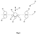
- an S-roll can be understood to mean a roll which is arranged in such a way that the support makes it S-shaped revolves, as is known to those skilled in the art and is described in detail below with reference to the figures.
- the carrier can be compressed in step e) by a factor of> 0% to ⁇ 7%, preferably> 0% to ⁇ 5%.
- method step e) can thus obtain a particularly smooth surface by means of a slight compression, since this method step can essentially be tuned to the smoothing or to the setting of the surface quality.
- the entire structure of the press, in particular the dual-band press can be aligned with smoothing and there is no need to focus on excessive compression, which can produce a particularly good surface image even at high throughputs.
- the invention relates to a device for producing a decorated wall or floor panel, which is characterized in that the device comprises means for performing a method configured as described above.
- the device comprises means for performing a method configured as described above.
- the invention relates to a wall or floor panel, produced according to a method described above, wherein a plate-shaped carrier has a profiling at least in one edge region.
- a profiling according to the invention it is provided that by means of suitable material-removing tools at least in one part the edges of the decorative panel a decorative and / or functional profile is introduced.
- a functional profile is understood, for example, to mean the introduction of a tongue and / or groove profile into an edge in order to make decorative panels connectable to each other via the introduced profilings.
- a decorative profile in the sense of the invention is, for example, a chamfer introduced in the edge region of the decorative panel in order to simulate, for example, a joint between two interconnected panels, as occurs, for example, in so-called plank flooring.
- the decorative profile to be provided in a panel such as a chamfer
- the functional profile for example tongue and groove
- the decor also corresponds to the desired imitation of a natural material, for example, in the areas of the profiling in a detailed manner.
- the print template used for printing in the area of the profiling of the panel can be distortion-compensated.
- Distortion compensation means in the context of the invention for example, for the exemplary case of application with a printing process by the deviation of the profiling of the surface plane of the Carrier, for example, at a chamfer edge, caused distortion of the print image is compensated by adjusting the artwork to the deviation. It may be provided, for example, that the compensation of the distortion by means of adjustment of the pixel spacing, the pixel size and / or the ink application depending on the intended edge profile of the finished decorative panel.
- the triggering of the print head can be effected as a function of the distortion to be compensated, so that the print head is deflected beyond the profiled area, for example, and the color output is adapted to the profile.
- the joints such as V-joints
- the decorative layer is applied to the carrier profiled in this way and the carrier is then divided at least in the profiled areas.
- the type of division such as, for example, sawing, laser cutting or water jet cutting, it can preferably be provided that the required cutting allowance in the introduced profile is taken into account.
- the plate-shaped carrier may comprise a material based on a WPC material or a PVC material.
- the carrier material wood and / or chalk having a particle size between ⁇ 0 and ⁇ 1000 ⁇ m, for example ⁇ 800 and ⁇ 1000 ⁇ m and a particle size distribution D50 of ⁇ 400 ⁇ m, preferably a particle size distribution D10 of ⁇ 400 ⁇ m, for example a particle size distribution D50 of ⁇ 600 ⁇ m, preferably a particle size distribution D10 of ⁇ 600 ⁇ m.
- the process can have further process steps in order to obtain the finished wall or floor panel.
- the device 10 according to FIG. 1 comprises first two circumferential band-like conveying means 12, 14 which are guided in particular by deflection rollers 16 such that between them a receiving space 18 for receiving and processing a provided pourable, in particular granular carrier material 20, such as based on a plastic, such as PVC, or a wood-plastic composite material, such as wood and PP, PE or a block copolymer comprising PP and PE, forms.
- the conveying means 12, 14 may be at least partially made of polytetrafluoroethylene, for example coated therewith.
- the conveying means 12, 14 may be at least partially roughened or structured, in particular on their side facing the receiving space 18. Further, the conveying means 12, 14 may have a width in a range of about 1.5 m.
- a discharge unit 22 is provided with one or a plurality of discharge heads 24, by means of which the carrier material 20 can be arranged on the lower conveying means 14.
- the discharge heads 24 may in this case comprise a funnel 25, which applies the carrier material 20 to corresponding scattering rollers 26, whereupon the carrier material 20 can be scattered onto the lower conveying means 14.
- a sensor for checking the arrangement of the carrier material 20 between two belt-like conveying means 12, 14 may be provided.
- the sensor may in particular be coupled to the discharge unit 22 in order to directly correct a potentially inaccurate filling of the receiving space 18.
- vibrators may also be provided. These can act approximately on the lower conveyor 14 and be arranged, for example, under the lower conveyor 14, so that the carrier material 20 is finely distributed.
- a device for introducing a fiber material into the receiving space 18 and thus be provided in the carrier can be designed like a belt and unwound from a roll.
- the fiber material may be arranged approximately between two discharge heads 24 in order, for example, to be able to arrange a different material above and below the fiber material.
- the fiber material can be introduced, for example, such that above and below the fiber material, a desired amount of support material 20 is located.
- a forming unit 28 is further provided, which is adapted to the carrier material 20 under the action of temperature or heat to fuse the carrier material 20 to form a web-shaped carrier 36 to shape.
- the molding unit 28 can have approximately two plate-like molding devices 30, 32, which can be heated by a heating device 34, for example by means of a thermal oil.
- the support material 20 may be heated until, depending on the melting point of the support material 20 or a part thereof, a temperature of, for example and depending on the material used, such as PVC or a WPV material, ⁇ 180 ° C to ⁇ 200 ° C has reached.
- the molding unit 28 or can Molding devices 30, 32 are heated, for example, to a temperature of up to 250 ° C.
- one or a plurality of independently adjustable heating areas can be provided for setting a temperature gradient.
- the entire shaping devices 30, 32 which may have a length of several meters, may be heatable, or only part of them may be heatable.
- the molding unit 28 may in particular have a parallel gap, which may be formed by the plate-like molding devices 30, 32.
- an inlet mouth can be provided at the inlet through a conical shape to allow an improved inlet of the carrier material 20.
- the force acting on the carrier material 20 may be fed in a range from> 0 kg / m 2, up to ⁇ 1 kg / m 2.
- a uniform pressurization without the provision of a pressure profile or a pressure gradient can be provided.
- the lower former 32 is longer than the upper former 30 and also begins before the upper. It can thereby be achieved that processing only takes place when the carrier material 20 has already been melted or at least melted on and at least partially softened. As a result, a particularly defined shaping process can be made possible.
- the pressing device 38 may for example comprise an S-roll, which in detail in the FIG. 2 is shown.
- the S-roll can be moved substantially perpendicular to the surface of the carrier 36 and thus to the direction of travel of the carrier 36, as indicated by the arrow 58, so that the desired pressures can be particularly advantageous adjustable.
- the pressing device 38 may, for example, on the carrier 36 exert a pressure that may be in a range of ⁇ 1kg / m 2 to ⁇ 3kg / m 2 .
- the S-roll comprises a main roller 60, which on the web-shaped carrier 36 acts.
- the belt tension may be sufficient as a back pressure, but it is preferred that at least one counter-pressure roller 62 is provided.
- two pairs of calender rolls 64 and, optionally, deflection rolls 66 can also be provided, which can furthermore provide for a suitable strip tension.
- the main roller 60 may be wrapped by the sheet-shaped carrier 36 in a range of about 50% or more.
- the temperature of the carrier 36 further corresponds to an inlet to the pressing device 38, in particular the temperature present at the output from the molding unit 28.
- the carrier 36 is subsequently guided to a further pressing device 40.
- a further tempering device 42 such as a heater, such as an IR heater, or preferably a cooling device to cool the support 36 may be provided between the pressing means 38, 40.
- the carrier 36 can also be cooled by a heating device, insofar as it transmits a temperature to the carrier, which is below the carrier temperature present in the tempering device 42 before the inlet, but above the room temperature.
- this advantageously can be a two-belt press, which in particular steel strips 44, 46 may have, which may be coated on the side facing the carrier 36 with polytetrafluoroethylene (Teflon) and wherein the bands 44, 46 of the two-band press by deflection rollers 48, 50 can be performed.
- the deflection rollers 48, 50 can be heated, for example, or advantageously cooled, for example by means of a thermal oil temperature control and / or the rollers on the same side of the gap may be arranged at a distance in a range of ⁇ 1m to ⁇ 2m, for example, 1.5m from each other, wherein the bands 44, 46 may have a width in a range of about 1.5m.
- the carrier 20 located between the conveying means 12, 14 is guided between the deflection rollers 48, 50 and thus between the belts 44, 46, in particular steel belts.
- pressing and / or tempering devices 52, 54 are provided, with which the carrier 36 can be cooled. These can both cool the conveying means 12, 14 and thus the carrier 36, as well as slightly compress.
- an air-cooling can be provided and a plurality of rollers, which can enable an intermittent pressing.
- a temperature of the tapes 44, 46 may be set in a range of ⁇ 150 ° C to ⁇ 180 ° C, for example, 170 ° C for the upper tape 44 and / or in a range of ⁇ 140 ° C to ⁇ 170 ° C, for example, be set at 160 ° C for the lower belt 46.
- the tempering device 52, 54 or by a plurality of tempering cooling zones in the direction of movement of the carrier 36 may be provided to adjust a temperature gradient. For example, such a successive cooling can be made possible.
- a first cooling zone may act on the bands 44, 46 which is in a range of ⁇ 55 ° C to ⁇ 85 ° C, for example, 72 ° C, and / or a second cooling zone may act on the bands 44, 46 , which is in a range of ⁇ 45 ° C to ⁇ 75 ° C, for example, 62 ° C, and / or may act on the belts 44, 46 in a third cooling zone, which ranges from ⁇ 15 ° C to ⁇ 45 ° C, for example at 30 ° C, is located.
- the temperature of the carrier in the pressing device 40 may be below the melting temperature or softening temperature of the carrier material or a part thereof.
- such a pressure can act on the carrier 36, that the carrier 36 is compressed in step e) by a factor of ⁇ 7.5%, preferably ⁇ 5%, for example in a range of ⁇ 0,1mm to ⁇ 0,2mm ,
- the pressing and / or heating devices 52, 54 can in the Substantially occupy the entire area between the pulleys 48, 50, or even a limited along the conveying direction area ..
- the pressing device 40 may have a variable pressure profile, such as in an area starting with 6mm and ending with 4.1mm, for example starting with 5.9mm and ending with 5.3mm, with intermediate stages of 5.7mm and 5.5mm or advantageous be designed as an isochore press.
- a cooling device 56 is arranged, through which the carrier can be cooled to a temperature which is for example in a range of ⁇ 35 ° C.
- the cooling device 56 may be based, for example, on a water cooling system and include a plurality of cooling zones, in order to allow a defined cooling using precisely customizable cooling programs.
- the length of the cooling zone can correspond to the effective length of the pressing device 40. After the cooling device 56 may still be provided another cooling belt.
- the support which may have a final thickness in a range of ⁇ 3 mm to ⁇ 5 mm, for example 4.1 mm, can be treated further directly, or be stored, for example as a web-shaped carrier 36 or as an already singly plate-shaped carrier.
Priority Applications (19)
| Application Number | Priority Date | Filing Date | Title |
|---|---|---|---|
| EP14167698.1A EP2942208A1 (fr) | 2014-05-09 | 2014-05-09 | Procédé de fabrication d'un panneau mural ou de sol décoré |
| CA2946664A CA2946664C (fr) | 2014-05-09 | 2015-04-28 | Procede de production d'un panneau de paroi ou de sol decore |
| PT15718891T PT3140129T (pt) | 2014-05-09 | 2015-04-28 | Método para fabrico de painel de parede ou de piso decorado |
| US15/310,017 US10479134B2 (en) | 2014-05-09 | 2015-04-28 | Method for producing a decorated wall or floor panel |
| ES15718891T ES2688149T5 (es) | 2014-05-09 | 2015-04-28 | Procedimiento para la fabricación de un panel de pared o de suelo decorado |
| MX2016014336A MX357984B (es) | 2014-05-09 | 2015-04-28 | Metodo para producir un panel decorado de piso o pared. |
| CN201580030762.9A CN106414101B (zh) | 2014-05-09 | 2015-04-28 | 一种用于生产装饰墙板或者地板镶板的方法 |
| JP2017510744A JP6503453B2 (ja) | 2014-05-09 | 2015-04-28 | 化粧壁パネルまたは化粧床パネルの製造方法 |
| AU2015257887A AU2015257887B2 (en) | 2014-05-09 | 2015-04-28 | Method for producing a decorated wall or floor panel |
| MYPI2016703981A MY189009A (en) | 2014-05-09 | 2015-04-28 | Method for producing a decorated wall or floor panel |
| EP15718891.3A EP3140129B2 (fr) | 2014-05-09 | 2015-04-28 | Procédé de fabrication d'un panneau mural ou de sol décoré |
| RU2016145070A RU2647233C1 (ru) | 2014-05-09 | 2015-04-28 | Способ изготовления декорированной стеновой или половой панели |
| PL15718891.3T PL3140129T5 (pl) | 2014-05-09 | 2015-04-28 | Sposób wytwarzania dekorowanego panelu ściennego lub podłogowego |
| UAA201610996A UA116062C2 (uk) | 2014-05-09 | 2015-04-28 | Спосіб виготовлення декорованої панелі для стіни або підлоги |
| KR1020167034432A KR101965944B1 (ko) | 2014-05-09 | 2015-04-28 | 장식 벽 또는 플로어 패널을 제조하기 위한 방법 |
| EP18173627.3A EP3403846B1 (fr) | 2014-05-09 | 2015-04-28 | Procédé de fabrication d'un panneau mural ou de sol décoré |
| BR112016024117-7A BR112016024117B1 (pt) | 2014-05-09 | 2015-04-28 | Método para produzir um painel de parede ou de piso decorado |
| PCT/EP2015/059220 WO2015169647A1 (fr) | 2014-05-09 | 2015-04-28 | Procédé de production d'un panneau de paroi ou de sol décoré |
| CL2016002755A CL2016002755A1 (es) | 2014-05-09 | 2016-10-28 | Método para fabricar un panel de pared o de piso decorado |
Applications Claiming Priority (1)
| Application Number | Priority Date | Filing Date | Title |
|---|---|---|---|
| EP14167698.1A EP2942208A1 (fr) | 2014-05-09 | 2014-05-09 | Procédé de fabrication d'un panneau mural ou de sol décoré |
Publications (1)
| Publication Number | Publication Date |
|---|---|
| EP2942208A1 true EP2942208A1 (fr) | 2015-11-11 |
Family
ID=50685783
Family Applications (3)
| Application Number | Title | Priority Date | Filing Date |
|---|---|---|---|
| EP14167698.1A Withdrawn EP2942208A1 (fr) | 2014-05-09 | 2014-05-09 | Procédé de fabrication d'un panneau mural ou de sol décoré |
| EP18173627.3A Active EP3403846B1 (fr) | 2014-05-09 | 2015-04-28 | Procédé de fabrication d'un panneau mural ou de sol décoré |
| EP15718891.3A Active EP3140129B2 (fr) | 2014-05-09 | 2015-04-28 | Procédé de fabrication d'un panneau mural ou de sol décoré |
Family Applications After (2)
| Application Number | Title | Priority Date | Filing Date |
|---|---|---|---|
| EP18173627.3A Active EP3403846B1 (fr) | 2014-05-09 | 2015-04-28 | Procédé de fabrication d'un panneau mural ou de sol décoré |
| EP15718891.3A Active EP3140129B2 (fr) | 2014-05-09 | 2015-04-28 | Procédé de fabrication d'un panneau mural ou de sol décoré |
Country Status (17)
| Country | Link |
|---|---|
| US (1) | US10479134B2 (fr) |
| EP (3) | EP2942208A1 (fr) |
| JP (1) | JP6503453B2 (fr) |
| KR (1) | KR101965944B1 (fr) |
| CN (1) | CN106414101B (fr) |
| AU (1) | AU2015257887B2 (fr) |
| BR (1) | BR112016024117B1 (fr) |
| CA (1) | CA2946664C (fr) |
| CL (1) | CL2016002755A1 (fr) |
| ES (1) | ES2688149T5 (fr) |
| MX (1) | MX357984B (fr) |
| MY (1) | MY189009A (fr) |
| PL (1) | PL3140129T5 (fr) |
| PT (1) | PT3140129T (fr) |
| RU (1) | RU2647233C1 (fr) |
| UA (1) | UA116062C2 (fr) |
| WO (1) | WO2015169647A1 (fr) |
Cited By (9)
| Publication number | Priority date | Publication date | Assignee | Title |
|---|---|---|---|---|
| CN107073742A (zh) * | 2015-08-19 | 2017-08-18 | 阿卡曾塔板材型材有限公司 | 用于生产装饰墙壁或地板的方法 |
| CN108481882A (zh) * | 2018-02-05 | 2018-09-04 | 重庆水利电力职业技术学院 | 一种布艺及墙纸集成墙板的制作设备 |
| CN109922971A (zh) * | 2016-10-27 | 2019-06-21 | 阿卡曾塔板材型材有限公司 | 用于制造装饰墙板或地板的方法 |
| WO2020035511A1 (fr) | 2018-08-14 | 2020-02-20 | Akzenta Paneele + Profile Gmbh | Plaque de support plastique multistratifiée et son procédé de fabrication |
| US10857832B2 (en) | 2015-09-24 | 2020-12-08 | Akzenta Paneele + Profile Gmbh | Method for producing a decorated wall or floor panel |
| US20210001616A1 (en) * | 2014-11-20 | 2021-01-07 | Ivc, Bv | Method for manufacturing a panel including a reinforcement sheet |
| CN112549752A (zh) * | 2020-11-24 | 2021-03-26 | 四川峻发鑫材环保设备有限公司 | 一种电磁加热硅胶辊及其加工方法 |
| EP3882040A1 (fr) * | 2020-03-20 | 2021-09-22 | Akzenta Paneele + Profile GmbH | Procédé d'application d'une feuille à un support au moyen d'une charge électrostatique |
| US11186709B2 (en) | 2018-06-05 | 2021-11-30 | Akzenta Paneele + Profile Gmbh | Carrier material on the base of a plastic composition and a mineral based solid composition for decorated wall or floor panels |
Families Citing this family (18)
| Publication number | Priority date | Publication date | Assignee | Title |
|---|---|---|---|---|
| DE102013103663B4 (de) | 2013-04-11 | 2014-10-23 | Nora Systems Gmbh | Verfahren zum Herstellen eines eine Dekorschicht aufweisenden Elastomer-Bodenbelags und Elastomer-Bodenbelag mit einer Dekorschicht |
| PT109256A (pt) * | 2016-03-22 | 2017-09-22 | Amorim Compcork Lda | Processo de preparação de placas de compósito de cortiça e polietileno |
| CN106671388A (zh) * | 2016-11-15 | 2017-05-17 | 安徽冠金绿可木业有限公司 | 一种防潮性强的木塑装饰板 |
| CN108232084B (zh) * | 2017-12-13 | 2021-01-12 | 浙江畅通科技有限公司 | 一种agm隔板生产系统 |
| EA202092298A1 (ru) | 2018-05-02 | 2021-02-25 | Ксило Технологис Аг | Способ и устройство для изготовления плиты, предназначенной для изготовления панелей, плита для изготовления панелей, способ и устройство для изготовления панелей и панель, изготавливаемая этим способом |
| UA127261C2 (uk) | 2018-05-02 | 2023-06-28 | Ліґнум Текнолоджіз Аґ | Спосіб та установка для виробництва дошки для виготовлення панелей, дошка для виготовлення панелей, спосіб та установка для виготовлення панелей і панель, вироблювана цим способом |
| DE102018119056A1 (de) * | 2018-08-06 | 2020-02-06 | Falquon Gmbh | Verfahren zum Verlegen und Verbinden von Bodenpaneelen und Bodenpaneel zum Verlegen mit dem Verfahren |
| CN109249494B (zh) * | 2018-10-08 | 2020-10-30 | 湖南广播电视大学 | 一种秸秆编织机的精确编织装置 |
| CN111055616A (zh) * | 2018-10-17 | 2020-04-24 | 苏州红泥新材料科技有限公司 | 一种带印刷图案的抗裂肌理夹芯及其制作方法 |
| CN110126157A (zh) * | 2019-06-20 | 2019-08-16 | 山东拓研新材料科技有限公司 | 一种新型的功能性热熔胶膜的制备工艺 |
| CN110450295A (zh) * | 2019-08-15 | 2019-11-15 | 中南林业科技大学 | 一种石塑地板基材物料混炼系统及方法 |
| US20240009948A1 (en) * | 2019-10-18 | 2024-01-11 | Välinge Innovation AB | Methods and arrangements for continuous manufacture of building panels |
| EP3822077B1 (fr) * | 2019-11-12 | 2022-01-26 | Flooring Technologies Ltd. | Procédé de fabrication d'une plaque contreplaquée |
| EP3835027A1 (fr) | 2019-12-11 | 2021-06-16 | Akzenta Paneele + Profile GmbH | Procédé et dispositif de fabrication d'un panneau mural ou de sol décoré |
| EP3892796A1 (fr) | 2020-04-08 | 2021-10-13 | Akzenta Paneele + Profile GmbH | Panneau décoratif à bords non parallèles à l'axe longitudinal et procédé de fabrication |
| EP4314439A1 (fr) * | 2021-03-30 | 2024-02-07 | Ceraloc Innovation AB | Procédé et ensemble de fabrication d'un élément de planche comprenant un matériau recyclé |
| WO2023199218A1 (fr) * | 2022-04-14 | 2023-10-19 | Sacmi Cooperativa Meccanici Imola Societa' Cooperativa | Système de fabrication et procédé de fabrication d'articles en céramique |
| US20240001663A1 (en) * | 2022-06-30 | 2024-01-04 | Continuus Materials Intellectual Property, Llc | Heat transfer system with improved efficiency for composite panel production |
Citations (4)
| Publication number | Priority date | Publication date | Assignee | Title |
|---|---|---|---|---|
| WO2002094523A1 (fr) * | 2001-05-24 | 2002-11-28 | Canti & Figli S.R.L. | Procede pour la fabrication de panneaux, carreaux et similaires au moyen d'agglomerats de differents mineraux |
| WO2007061193A1 (fr) * | 2005-11-28 | 2007-05-31 | Lg Chem, Ltd. | Processus en ligne pour preparer un panneau composite bois-plastique dont l'apparence et la texture rappellent celles de bois d'oeuvre naturels, et dispositif a cet effet |
| WO2009065769A2 (fr) * | 2007-11-19 | 2009-05-28 | Välinge Innovation Belgium BVBA | Panneaux à base de fibres présentant une surface de résistance à l'usure |
| US20090202810A1 (en) * | 2008-02-13 | 2009-08-13 | Microposite, Inc. | Process and Machine for Manufacturing Lap Siding and the Product Made Thereby |
Family Cites Families (44)
| Publication number | Priority date | Publication date | Assignee | Title |
|---|---|---|---|---|
| LU35293A1 (fr) * | 1956-07-18 | |||
| GB994894A (en) | 1961-01-28 | 1965-06-10 | Shigenari Soda | Improvements relating to the treatment of resinous material |
| DE2113763B2 (de) | 1971-03-22 | 1976-04-15 | Bison-Werke Bahre und Greten GmbH & Co KG, 3257 Springe | Vorrichtung zum kontinuierlichen herstellen von spanplatten |
| US4290248A (en) † | 1975-01-06 | 1981-09-22 | William James Kemerer | Continuous process for forming products from thermoplastic polymeric material having three-dimensional patterns and surface textures |
| DE3530309A1 (de) | 1985-08-24 | 1987-02-26 | Held Kurt | Verfahren und vorrichtung zum kontinuierlichen herstellen thermoplastischer kunststoffbahnen |
| JPH06102647B2 (ja) | 1990-07-03 | 1994-12-14 | 株式会社日本触媒 | システアミン塩酸塩の造粒方法およびその装置 |
| SE501526C2 (sv) | 1992-08-27 | 1995-03-06 | Bjoern Keding | Metod att härda lackerade skivmaterial med elektronstrålning |
| JP2968470B2 (ja) | 1996-02-15 | 1999-10-25 | 三木特種製紙株式会社 | 板状製品の連続製造装置及び方法 |
| JP2992550B2 (ja) | 1996-04-27 | 1999-12-20 | 株式会社ノダ | 建築用材およびその製造方法 |
| JPH10166321A (ja) | 1996-12-12 | 1998-06-23 | Riboole:Kk | 複合合成木材 |
| GB2324982B (en) | 1997-10-01 | 1999-06-30 | Samuel Louis Pieters | Applying a pattern to a substrate |
| DE19751516C2 (de) † | 1997-11-21 | 2003-04-03 | Schilling Knobel Gmbh | Verfahren zur Herstellung von thermofixierten Bahnen aus thermoplastischen Polymer-Materialteilchen |
| JPH11333983A (ja) | 1998-05-27 | 1999-12-07 | Kawai Musical Instr Mfg Co Ltd | 木質化粧材およびその製造方法 |
| DE19842510A1 (de) | 1998-09-17 | 2000-03-23 | Reisewitz Beschichtungs Gmbh | Verfahren zur Strukturierung der Oberfläche strahlenhärtbarer Lacke und Farben mittels kurzwelliger UV-Strahlung |
| SE516696C2 (sv) | 1999-12-23 | 2002-02-12 | Perstorp Flooring Ab | Förfarande för framställning av ytelement vilka innefattar ett övre dekorativt skikt samt ytelement framställda enlit förfarandet |
| JP4132551B2 (ja) * | 2000-03-07 | 2008-08-13 | ニチハ株式会社 | 木質成形体の製造方法 |
| DE10019054C1 (de) | 2000-04-18 | 2001-12-13 | Kronotec Ag | Verfahren zum Zuschneiden von Paneelen oder dergleichen |
| CH694160A5 (fr) | 2000-05-11 | 2004-08-13 | Bobst Sa | Dispositif de gestion des défauts d'impression détectés au sein d'une machine d'impression. |
| SE0003550L (sv) | 2000-10-03 | 2002-04-04 | Pergo Ab | Förfarande för framställning av ytelement |
| ITPS20010006A1 (it) * | 2001-02-23 | 2002-08-23 | Canti & Figli Srl | Procedimento e macchina atti ad ottenere goffrature su superfici verniciate di pannelli o di pellicole di rivestimento ed elementi ottenuti |
| DE10114381A1 (de) | 2001-03-23 | 2002-10-10 | Metso Paper Inc | Verfahren zur kontinuierlichen Herstellung von Holzspanplatten und ähnlichen bahnförmigen Plattenwerkstoffen und dafür geeignete Doppelbandpresse |
| US7081291B2 (en) | 2002-01-11 | 2006-07-25 | Domco Tarkett Inc. | Selectively embossed surface coverings and processes of manufacture |
| DE10205894A1 (de) | 2002-02-13 | 2003-08-21 | Dieffenbacher Gmbh Maschf | Verfahren und kontinuierlich arbeitende Presse zur kontinuierlichen Herstellung von Holzwerkstoffplatten |
| DE10319771B4 (de) | 2003-05-02 | 2005-03-17 | Koenig & Bauer Ag | System zur Inspektion eines Druckbildes |
| EP1842661B1 (fr) | 2005-01-24 | 2010-12-01 | Dai Nippon Printing Co., Ltd. | Feuille decorative et panneau decoratif sur lequel la feuille est apposee |
| JP2007210326A (ja) | 2006-01-12 | 2007-08-23 | Komori Corp | シート状物の仕分け方法及び装置 |
| JP4902437B2 (ja) | 2006-09-27 | 2012-03-21 | 富士フイルム株式会社 | インクジェット記録方法およびインクジェット記録装置 |
| DE602007011013D1 (de) | 2006-09-27 | 2011-01-20 | Fujifilm Corp | Etikettendrucker und Verfahren zur Etikettenerzeugung |
| PL1914052T3 (pl) * | 2006-10-19 | 2017-12-29 | Basf Se | Lekkie tworzywa drzewne |
| ATE522282T1 (de) | 2006-11-23 | 2011-09-15 | Kronoplus Technical Ag | Verfahren zum direktbedrucken von holzwerkstoffplatten |
| EP3572223A3 (fr) * | 2007-04-10 | 2020-01-15 | Unilin, BVBA | Procédé et appareil de fabrication de panneaux de plancher lamellés comportant une âme contenant un composite bois/matière plastique et panneaux ainsi obtenus |
| PL2602077T3 (pl) | 2007-11-19 | 2017-12-29 | Välinge Innovation AB | Odzyskiwanie laminowanych podłóg |
| DE102007063261B4 (de) † | 2007-12-17 | 2023-03-02 | Ipco Germany Gmbh | Anlage zur Herstellung von bahn- oder plattenförmigen Belägen |
| JP5156363B2 (ja) | 2007-12-25 | 2013-03-06 | パナソニック株式会社 | 板状建材の塗装方法 |
| JP5161123B2 (ja) | 2009-01-16 | 2013-03-13 | 古河機械金属株式会社 | 複合木材の製造方法 |
| US8808863B2 (en) | 2009-07-28 | 2014-08-19 | Photokinetic Coatings & Adhesives, Llc | UV-curable floor sealants |
| PL2589499T3 (pl) | 2010-06-30 | 2014-10-31 | Flooring Technologies Ltd | Zagruntowany panel z rdzeniem z tworzywa drzewnego |
| DE102010033578A1 (de) | 2010-08-03 | 2012-02-09 | Sandvik Materials Technology Deutschland Gmbh | Doppelbandpresse und Verfahren zum Herstellen eines plattenförmigen Produkts mit einer Doppelbandpresse |
| DE102011001807B4 (de) | 2011-04-05 | 2024-02-08 | Guido Schulte | Bodenpaneel und Verfahren zu deren Herstellung |
| US9169396B2 (en) | 2011-01-19 | 2015-10-27 | TPS TechnoPartner Samtronic GmbH | Polymer-bound web as well as method for its production |
| CN104136179B (zh) * | 2011-12-23 | 2016-10-12 | 巴斯夫欧洲公司 | 在外层具有木质纤维素纤维且在芯中存在发泡塑料颗粒的木质纤维素材料及其方法和用途 |
| BE1020722A3 (nl) | 2012-06-01 | 2014-04-01 | Unilin Bvba | Paneel voor het vormen van een vloerbekleding en werkwijze voor het vervaardigen van dergelijke panelen. |
| EP2829415A1 (fr) * | 2013-07-22 | 2015-01-28 | Akzenta Paneele + Profile GmbH | Procédé de fabrication d'un panneau mural et de sol décoré |
| ES2687372T3 (es) | 2013-07-22 | 2018-10-24 | Akzenta Paneele + Profile Gmbh | Procedimiento para la fabricación de un panel decorado de pared o de suelo |
-
2014
- 2014-05-09 EP EP14167698.1A patent/EP2942208A1/fr not_active Withdrawn
-
2015
- 2015-04-28 MY MYPI2016703981A patent/MY189009A/en unknown
- 2015-04-28 UA UAA201610996A patent/UA116062C2/uk unknown
- 2015-04-28 PT PT15718891T patent/PT3140129T/pt unknown
- 2015-04-28 EP EP18173627.3A patent/EP3403846B1/fr active Active
- 2015-04-28 BR BR112016024117-7A patent/BR112016024117B1/pt active IP Right Grant
- 2015-04-28 MX MX2016014336A patent/MX357984B/es active IP Right Grant
- 2015-04-28 KR KR1020167034432A patent/KR101965944B1/ko active IP Right Grant
- 2015-04-28 CA CA2946664A patent/CA2946664C/fr active Active
- 2015-04-28 EP EP15718891.3A patent/EP3140129B2/fr active Active
- 2015-04-28 ES ES15718891T patent/ES2688149T5/es active Active
- 2015-04-28 CN CN201580030762.9A patent/CN106414101B/zh active Active
- 2015-04-28 US US15/310,017 patent/US10479134B2/en active Active
- 2015-04-28 PL PL15718891.3T patent/PL3140129T5/pl unknown
- 2015-04-28 AU AU2015257887A patent/AU2015257887B2/en active Active
- 2015-04-28 WO PCT/EP2015/059220 patent/WO2015169647A1/fr active Application Filing
- 2015-04-28 RU RU2016145070A patent/RU2647233C1/ru active
- 2015-04-28 JP JP2017510744A patent/JP6503453B2/ja active Active
-
2016
- 2016-10-28 CL CL2016002755A patent/CL2016002755A1/es unknown
Patent Citations (4)
| Publication number | Priority date | Publication date | Assignee | Title |
|---|---|---|---|---|
| WO2002094523A1 (fr) * | 2001-05-24 | 2002-11-28 | Canti & Figli S.R.L. | Procede pour la fabrication de panneaux, carreaux et similaires au moyen d'agglomerats de differents mineraux |
| WO2007061193A1 (fr) * | 2005-11-28 | 2007-05-31 | Lg Chem, Ltd. | Processus en ligne pour preparer un panneau composite bois-plastique dont l'apparence et la texture rappellent celles de bois d'oeuvre naturels, et dispositif a cet effet |
| WO2009065769A2 (fr) * | 2007-11-19 | 2009-05-28 | Välinge Innovation Belgium BVBA | Panneaux à base de fibres présentant une surface de résistance à l'usure |
| US20090202810A1 (en) * | 2008-02-13 | 2009-08-13 | Microposite, Inc. | Process and Machine for Manufacturing Lap Siding and the Product Made Thereby |
Cited By (15)
| Publication number | Priority date | Publication date | Assignee | Title |
|---|---|---|---|---|
| US20210001616A1 (en) * | 2014-11-20 | 2021-01-07 | Ivc, Bv | Method for manufacturing a panel including a reinforcement sheet |
| CN107073742A (zh) * | 2015-08-19 | 2017-08-18 | 阿卡曾塔板材型材有限公司 | 用于生产装饰墙壁或地板的方法 |
| US10857832B2 (en) | 2015-09-24 | 2020-12-08 | Akzenta Paneele + Profile Gmbh | Method for producing a decorated wall or floor panel |
| CN109922971A (zh) * | 2016-10-27 | 2019-06-21 | 阿卡曾塔板材型材有限公司 | 用于制造装饰墙板或地板的方法 |
| US11065911B2 (en) | 2016-10-27 | 2021-07-20 | Akzenta Paneele + Profile Gmbh | Method for producing a decorated wall or floor panel |
| CN109922971B (zh) * | 2016-10-27 | 2021-08-17 | 阿卡曾塔板材型材有限公司 | 用于制造装饰墙板或地板的方法 |
| CN108481882A (zh) * | 2018-02-05 | 2018-09-04 | 重庆水利电力职业技术学院 | 一种布艺及墙纸集成墙板的制作设备 |
| US11186709B2 (en) | 2018-06-05 | 2021-11-30 | Akzenta Paneele + Profile Gmbh | Carrier material on the base of a plastic composition and a mineral based solid composition for decorated wall or floor panels |
| WO2020035511A1 (fr) | 2018-08-14 | 2020-02-20 | Akzenta Paneele + Profile Gmbh | Plaque de support plastique multistratifiée et son procédé de fabrication |
| DE102018119766B4 (de) | 2018-08-14 | 2023-03-23 | Akzenta Paneele + Profile Gmbh | Multilaminares Kunststoffträgermaterial, Verfahren zu dessen Herstellung und Dekorpaneel |
| US11198278B2 (en) | 2018-08-14 | 2021-12-14 | Akzenta Paneele + Profile Gmbh | Multi-laminate plastic carrier plate and method for the production thereof |
| EP3882040A1 (fr) * | 2020-03-20 | 2021-09-22 | Akzenta Paneele + Profile GmbH | Procédé d'application d'une feuille à un support au moyen d'une charge électrostatique |
| WO2021185656A1 (fr) * | 2020-03-20 | 2021-09-23 | Akzenta Paneele + Profile Gmbh | Procédé de production d'un panneau décoratif comprenant l'application d'un film sur un substrat au moyen d'une charge électrostatique |
| CN112549752B (zh) * | 2020-11-24 | 2022-08-09 | 四川峻发鑫材环保设备有限公司 | 一种电磁加热硅胶辊及其加工方法 |
| CN112549752A (zh) * | 2020-11-24 | 2021-03-26 | 四川峻发鑫材环保设备有限公司 | 一种电磁加热硅胶辊及其加工方法 |
Also Published As
| Publication number | Publication date |
|---|---|
| PL3140129T3 (pl) | 2018-12-31 |
| AU2015257887B2 (en) | 2018-08-09 |
| BR112016024117A2 (pt) | 2017-08-15 |
| EP3403846A1 (fr) | 2018-11-21 |
| AU2015257887A1 (en) | 2016-11-17 |
| EP3140129B2 (fr) | 2022-06-22 |
| BR112016024117B1 (pt) | 2022-05-03 |
| CL2016002755A1 (es) | 2017-02-03 |
| PL3140129T5 (pl) | 2022-11-07 |
| MX357984B (es) | 2018-07-31 |
| ES2688149T3 (es) | 2018-10-31 |
| MY189009A (en) | 2022-01-18 |
| EP3403846B1 (fr) | 2021-08-18 |
| WO2015169647A1 (fr) | 2015-11-12 |
| CN106414101B (zh) | 2019-10-18 |
| MX2016014336A (es) | 2017-04-10 |
| KR20160149306A (ko) | 2016-12-27 |
| CA2946664C (fr) | 2019-08-20 |
| EP3140129A1 (fr) | 2017-03-15 |
| ES2688149T5 (es) | 2022-09-15 |
| CN106414101A (zh) | 2017-02-15 |
| RU2647233C1 (ru) | 2018-03-14 |
| JP6503453B2 (ja) | 2019-04-17 |
| EP3140129B1 (fr) | 2018-07-04 |
| CA2946664A1 (fr) | 2015-11-12 |
| PT3140129T (pt) | 2018-10-22 |
| US20170157977A1 (en) | 2017-06-08 |
| JP2017515713A (ja) | 2017-06-15 |
| UA116062C2 (uk) | 2018-01-25 |
| KR101965944B1 (ko) | 2019-04-04 |
| US10479134B2 (en) | 2019-11-19 |
Similar Documents
| Publication | Publication Date | Title |
|---|---|---|
| EP3140129B1 (fr) | Procédé de fabrication d'un panneau mural ou de sol décoré | |
| EP3024669B1 (fr) | Procédé de fabrication d'un panneau mural et de sol décoré | |
| EP2829415A1 (fr) | Procédé de fabrication d'un panneau mural et de sol décoré | |
| EP3178652B1 (fr) | Panneau de decoration et son procede de fabrication | |
| EP2739487B1 (fr) | Procédé de fabrication d'un panneau décoré mural, pour plafond ou plancher | |
| EP2730429B1 (fr) | Procédé de fabrication d'un panneau mural ou de sol décoré | |
| EP3147135B1 (fr) | Procede de fabrication d'un panneau mural ou de sol decore | |
| EP2930031B9 (fr) | Panneau décoratif en composite bois-plastique (WPC) doté d'un bord profilé peu poreuse et son procédé de fabrication | |
| EP2909038A1 (fr) | Procédé de fabrication d'un panneau mural ou de sol décoré | |
| EP3578384A1 (fr) | Matériau porteur à base d'une composition de matière plastique et d'une composition de matière solide minérales pour panneaux muraux ou de sol décorés | |
| EP3132945B1 (fr) | Procede de fabrication d'un panneau mural ou de sol decore | |
| EP3088204B1 (fr) | Procédé de fabrication d'un panneau mural ou de sol décoré | |
| WO2021115653A1 (fr) | Méthode et dispositif de production d'un panneau décoratif pour un mur ou pour un sol | |
| EP3088205A1 (fr) | Procédé de fabrication d'un panneau mural ou de sol décoré | |
| EP3543034A1 (fr) | Plaque porteuse pour un panneau de paroi, de sol ou de plafond directement imprimés |
Legal Events
| Date | Code | Title | Description |
|---|---|---|---|
| PUAI | Public reference made under article 153(3) epc to a published international application that has entered the european phase |
Free format text: ORIGINAL CODE: 0009012 |
|
| AK | Designated contracting states |
Kind code of ref document: A1 Designated state(s): AL AT BE BG CH CY CZ DE DK EE ES FI FR GB GR HR HU IE IS IT LI LT LU LV MC MK MT NL NO PL PT RO RS SE SI SK SM TR |
|
| AX | Request for extension of the european patent |
Extension state: BA ME |
|
| STAA | Information on the status of an ep patent application or granted ep patent |
Free format text: STATUS: THE APPLICATION IS DEEMED TO BE WITHDRAWN |
|
| 18D | Application deemed to be withdrawn |
Effective date: 20160512 |