EP3024669B1 - Procédé de fabrication d'un panneau mural et de sol décoré - Google Patents
Procédé de fabrication d'un panneau mural et de sol décoré Download PDFInfo
- Publication number
- EP3024669B1 EP3024669B1 EP14739847.3A EP14739847A EP3024669B1 EP 3024669 B1 EP3024669 B1 EP 3024669B1 EP 14739847 A EP14739847 A EP 14739847A EP 3024669 B1 EP3024669 B1 EP 3024669B1
- Authority
- EP
- European Patent Office
- Prior art keywords
- carrier
- carrier material
- wood
- particle size
- decor
- Prior art date
- Legal status (The legal status is an assumption and is not a legal conclusion. Google has not performed a legal analysis and makes no representation as to the accuracy of the status listed.)
- Active
Links
- 238000004519 manufacturing process Methods 0.000 title claims description 30
- 238000000034 method Methods 0.000 claims description 111
- 239000012876 carrier material Substances 0.000 claims description 96
- 239000000463 material Substances 0.000 claims description 92
- 239000002245 particle Substances 0.000 claims description 64
- 239000002023 wood Substances 0.000 claims description 43
- 238000009826 distribution Methods 0.000 claims description 29
- -1 polyethylene Polymers 0.000 claims description 24
- 239000002657 fibrous material Substances 0.000 claims description 21
- 238000001816 cooling Methods 0.000 claims description 20
- 239000004743 Polypropylene Substances 0.000 claims description 17
- 229920001155 polypropylene Polymers 0.000 claims description 17
- 238000003825 pressing Methods 0.000 claims description 17
- 239000008187 granular material Substances 0.000 claims description 15
- 239000004698 Polyethylene Substances 0.000 claims description 14
- 229920000573 polyethylene Polymers 0.000 claims description 14
- 239000011155 wood-plastic composite Substances 0.000 claims description 13
- 238000000465 moulding Methods 0.000 claims description 12
- 229920003023 plastic Polymers 0.000 claims description 11
- 239000004033 plastic Substances 0.000 claims description 11
- 239000011241 protective layer Substances 0.000 claims description 11
- 239000011148 porous material Substances 0.000 claims description 10
- 238000002844 melting Methods 0.000 claims description 7
- 230000008018 melting Effects 0.000 claims description 7
- 239000004005 microsphere Substances 0.000 claims description 5
- 229920001577 copolymer Polymers 0.000 claims description 4
- 238000003892 spreading Methods 0.000 claims description 4
- 230000007480 spreading Effects 0.000 claims description 4
- 229920001587 Wood-plastic composite Polymers 0.000 claims description 3
- 230000009977 dual effect Effects 0.000 claims 1
- 230000001939 inductive effect Effects 0.000 claims 1
- 239000010410 layer Substances 0.000 description 47
- 239000000203 mixture Substances 0.000 description 32
- 239000000758 substrate Substances 0.000 description 18
- 238000005034 decoration Methods 0.000 description 15
- 238000007639 printing Methods 0.000 description 15
- 239000004800 polyvinyl chloride Substances 0.000 description 13
- 229920000915 polyvinyl chloride Polymers 0.000 description 13
- 230000008569 process Effects 0.000 description 13
- 238000007906 compression Methods 0.000 description 12
- 229920000642 polymer Polymers 0.000 description 12
- 230000006835 compression Effects 0.000 description 11
- 230000005855 radiation Effects 0.000 description 11
- 230000009471 action Effects 0.000 description 10
- 230000008901 benefit Effects 0.000 description 10
- 238000012545 processing Methods 0.000 description 10
- 239000000654 additive Substances 0.000 description 9
- 239000000969 carrier Substances 0.000 description 9
- UHESRSKEBRADOO-UHFFFAOYSA-N ethyl carbamate;prop-2-enoic acid Chemical compound OC(=O)C=C.CCOC(N)=O UHESRSKEBRADOO-UHFFFAOYSA-N 0.000 description 9
- 238000007493 shaping process Methods 0.000 description 9
- 239000000123 paper Substances 0.000 description 8
- 238000010438 heat treatment Methods 0.000 description 7
- 239000012963 UV stabilizer Substances 0.000 description 6
- 239000011162 core material Substances 0.000 description 6
- 229920005989 resin Polymers 0.000 description 6
- 239000011347 resin Substances 0.000 description 6
- 239000007787 solid Substances 0.000 description 6
- XLYOFNOQVPJJNP-UHFFFAOYSA-N water Substances O XLYOFNOQVPJJNP-UHFFFAOYSA-N 0.000 description 6
- 229910000831 Steel Inorganic materials 0.000 description 5
- 235000013339 cereals Nutrition 0.000 description 5
- 238000013461 design Methods 0.000 description 5
- 239000012760 heat stabilizer Substances 0.000 description 5
- 239000005445 natural material Substances 0.000 description 5
- 239000008188 pellet Substances 0.000 description 5
- 229920001343 polytetrafluoroethylene Polymers 0.000 description 5
- 239000004810 polytetrafluoroethylene Substances 0.000 description 5
- 239000010959 steel Substances 0.000 description 5
- JOYRKODLDBILNP-UHFFFAOYSA-N Ethyl urethane Chemical compound CCOC(N)=O JOYRKODLDBILNP-UHFFFAOYSA-N 0.000 description 4
- 229920001400 block copolymer Polymers 0.000 description 4
- 239000011093 chipboard Substances 0.000 description 4
- 150000001875 compounds Chemical class 0.000 description 4
- 238000001723 curing Methods 0.000 description 4
- 238000005520 cutting process Methods 0.000 description 4
- 238000007599 discharging Methods 0.000 description 4
- 230000005670 electromagnetic radiation Effects 0.000 description 4
- 238000009499 grossing Methods 0.000 description 4
- 230000036961 partial effect Effects 0.000 description 4
- WSFSSNUMVMOOMR-UHFFFAOYSA-N Formaldehyde Chemical compound O=C WSFSSNUMVMOOMR-UHFFFAOYSA-N 0.000 description 3
- VYPSYNLAJGMNEJ-UHFFFAOYSA-N Silicium dioxide Chemical compound O=[Si]=O VYPSYNLAJGMNEJ-UHFFFAOYSA-N 0.000 description 3
- 125000001931 aliphatic group Chemical group 0.000 description 3
- 125000004432 carbon atom Chemical group C* 0.000 description 3
- 239000011248 coating agent Substances 0.000 description 3
- 238000000576 coating method Methods 0.000 description 3
- 238000010017 direct printing Methods 0.000 description 3
- 239000011094 fiberboard Substances 0.000 description 3
- 229920001519 homopolymer Polymers 0.000 description 3
- 229910052751 metal Inorganic materials 0.000 description 3
- 239000002184 metal Substances 0.000 description 3
- 239000003921 oil Substances 0.000 description 3
- 239000000049 pigment Substances 0.000 description 3
- 239000004014 plasticizer Substances 0.000 description 3
- 239000011120 plywood Substances 0.000 description 3
- 229920002959 polymer blend Polymers 0.000 description 3
- 238000011417 postcuring Methods 0.000 description 3
- 239000002994 raw material Substances 0.000 description 3
- 230000009467 reduction Effects 0.000 description 3
- 230000002829 reductive effect Effects 0.000 description 3
- 229920001169 thermoplastic Polymers 0.000 description 3
- 239000004416 thermosoftening plastic Substances 0.000 description 3
- GNFTZDOKVXKIBK-UHFFFAOYSA-N 3-(2-methoxyethoxy)benzohydrazide Chemical compound COCCOC1=CC=CC(C(=O)NN)=C1 GNFTZDOKVXKIBK-UHFFFAOYSA-N 0.000 description 2
- IJGRMHOSHXDMSA-UHFFFAOYSA-N Atomic nitrogen Chemical compound N#N IJGRMHOSHXDMSA-UHFFFAOYSA-N 0.000 description 2
- 235000017166 Bambusa arundinacea Nutrition 0.000 description 2
- 235000017491 Bambusa tulda Nutrition 0.000 description 2
- VTYYLEPIZMXCLO-UHFFFAOYSA-L Calcium carbonate Chemical compound [Ca+2].[O-]C([O-])=O VTYYLEPIZMXCLO-UHFFFAOYSA-L 0.000 description 2
- RTZKZFJDLAIYFH-UHFFFAOYSA-N Diethyl ether Chemical compound CCOCC RTZKZFJDLAIYFH-UHFFFAOYSA-N 0.000 description 2
- 229920000877 Melamine resin Polymers 0.000 description 2
- 241001465754 Metazoa Species 0.000 description 2
- 244000082204 Phyllostachys viridis Species 0.000 description 2
- 235000015334 Phyllostachys viridis Nutrition 0.000 description 2
- 239000004696 Poly ether ether ketone Substances 0.000 description 2
- 239000004952 Polyamide Substances 0.000 description 2
- 229920002522 Wood fibre Polymers 0.000 description 2
- 125000002947 alkylene group Chemical group 0.000 description 2
- PNEYBMLMFCGWSK-UHFFFAOYSA-N aluminium oxide Inorganic materials [O-2].[O-2].[O-2].[Al+3].[Al+3] PNEYBMLMFCGWSK-UHFFFAOYSA-N 0.000 description 2
- 239000011425 bamboo Substances 0.000 description 2
- 239000011230 binding agent Substances 0.000 description 2
- 230000015572 biosynthetic process Effects 0.000 description 2
- 229910052796 boron Inorganic materials 0.000 description 2
- 239000000919 ceramic Substances 0.000 description 2
- 239000003795 chemical substances by application Substances 0.000 description 2
- 239000000470 constituent Substances 0.000 description 2
- 125000002993 cycloalkylene group Chemical group 0.000 description 2
- 238000002050 diffraction method Methods 0.000 description 2
- 239000003085 diluting agent Substances 0.000 description 2
- 238000006073 displacement reaction Methods 0.000 description 2
- 230000000694 effects Effects 0.000 description 2
- 229920001971 elastomer Polymers 0.000 description 2
- 238000004049 embossing Methods 0.000 description 2
- 239000000835 fiber Substances 0.000 description 2
- 239000000945 filler Substances 0.000 description 2
- 239000006260 foam Substances 0.000 description 2
- 229910052500 inorganic mineral Inorganic materials 0.000 description 2
- 238000009413 insulation Methods 0.000 description 2
- 238000007648 laser printing Methods 0.000 description 2
- 125000002496 methyl group Chemical group [H]C([H])([H])* 0.000 description 2
- 239000011707 mineral Substances 0.000 description 2
- 238000007645 offset printing Methods 0.000 description 2
- 230000003287 optical effect Effects 0.000 description 2
- 238000005554 pickling Methods 0.000 description 2
- 229920003229 poly(methyl methacrylate) Polymers 0.000 description 2
- 229920002647 polyamide Polymers 0.000 description 2
- 229920002530 polyetherether ketone Polymers 0.000 description 2
- 239000005020 polyethylene terephthalate Substances 0.000 description 2
- 229920000139 polyethylene terephthalate Polymers 0.000 description 2
- 239000002861 polymer material Substances 0.000 description 2
- 239000004926 polymethyl methacrylate Substances 0.000 description 2
- 229920002635 polyurethane Polymers 0.000 description 2
- 239000004814 polyurethane Substances 0.000 description 2
- 238000002360 preparation method Methods 0.000 description 2
- 239000011342 resin composition Substances 0.000 description 2
- 239000005060 rubber Substances 0.000 description 2
- 238000007650 screen-printing Methods 0.000 description 2
- 239000010902 straw Substances 0.000 description 2
- 230000008961 swelling Effects 0.000 description 2
- 230000001360 synchronised effect Effects 0.000 description 2
- 235000013311 vegetables Nutrition 0.000 description 2
- 239000002025 wood fiber Substances 0.000 description 2
- RNFJDJUURJAICM-UHFFFAOYSA-N 2,2,4,4,6,6-hexaphenoxy-1,3,5-triaza-2$l^{5},4$l^{5},6$l^{5}-triphosphacyclohexa-1,3,5-triene Chemical compound N=1P(OC=2C=CC=CC=2)(OC=2C=CC=CC=2)=NP(OC=2C=CC=CC=2)(OC=2C=CC=CC=2)=NP=1(OC=1C=CC=CC=1)OC1=CC=CC=C1 RNFJDJUURJAICM-UHFFFAOYSA-N 0.000 description 1
- 239000001763 2-hydroxyethyl(trimethyl)azanium Substances 0.000 description 1
- 125000003903 2-propenyl group Chemical group [H]C([*])([H])C([H])=C([H])[H] 0.000 description 1
- 241000208140 Acer Species 0.000 description 1
- 239000004923 Acrylic lacquer Substances 0.000 description 1
- 229920001817 Agar Polymers 0.000 description 1
- 229910052580 B4C Inorganic materials 0.000 description 1
- 235000018185 Betula X alpestris Nutrition 0.000 description 1
- 235000018212 Betula X uliginosa Nutrition 0.000 description 1
- 239000002028 Biomass Substances 0.000 description 1
- 241000167854 Bourreria succulenta Species 0.000 description 1
- FGUUSXIOTUKUDN-IBGZPJMESA-N C1(=CC=CC=C1)N1C2=C(NC([C@H](C1)NC=1OC(=NN=1)C1=CC=CC=C1)=O)C=CC=C2 Chemical compound C1(=CC=CC=C1)N1C2=C(NC([C@H](C1)NC=1OC(=NN=1)C1=CC=CC=C1)=O)C=CC=C2 FGUUSXIOTUKUDN-IBGZPJMESA-N 0.000 description 1
- 241001070941 Castanea Species 0.000 description 1
- 235000014036 Castanea Nutrition 0.000 description 1
- 229920003043 Cellulose fiber Polymers 0.000 description 1
- 244000060020 Chamaerops excelsa Species 0.000 description 1
- 235000013164 Chamaerops excelsa Nutrition 0.000 description 1
- 235000019743 Choline chloride Nutrition 0.000 description 1
- 229920000742 Cotton Polymers 0.000 description 1
- 241000195493 Cryptophyta Species 0.000 description 1
- 239000004641 Diallyl-phthalate Substances 0.000 description 1
- 240000003133 Elaeis guineensis Species 0.000 description 1
- 235000001950 Elaeis guineensis Nutrition 0.000 description 1
- GYHNNYVSQQEPJS-UHFFFAOYSA-N Gallium Chemical compound [Ga] GYHNNYVSQQEPJS-UHFFFAOYSA-N 0.000 description 1
- 241000013479 Guibourtia coleosperma Species 0.000 description 1
- 240000007049 Juglans regia Species 0.000 description 1
- 235000009496 Juglans regia Nutrition 0.000 description 1
- 102000011782 Keratins Human genes 0.000 description 1
- 108010076876 Keratins Proteins 0.000 description 1
- 239000004640 Melamine resin Substances 0.000 description 1
- 239000004793 Polystyrene Substances 0.000 description 1
- 235000016976 Quercus macrolepis Nutrition 0.000 description 1
- 229910052581 Si3N4 Inorganic materials 0.000 description 1
- 244000186561 Swietenia macrophylla Species 0.000 description 1
- 239000004809 Teflon Substances 0.000 description 1
- 229920006362 Teflon® Polymers 0.000 description 1
- NRTOMJZYCJJWKI-UHFFFAOYSA-N Titanium nitride Chemical compound [Ti]#N NRTOMJZYCJJWKI-UHFFFAOYSA-N 0.000 description 1
- 229920001807 Urea-formaldehyde Polymers 0.000 description 1
- 244000208876 Washingtonia filifera Species 0.000 description 1
- 235000006574 Washingtonia filifera Nutrition 0.000 description 1
- 240000008042 Zea mays Species 0.000 description 1
- 235000005824 Zea mays ssp. parviglumis Nutrition 0.000 description 1
- 235000002017 Zea mays subsp mays Nutrition 0.000 description 1
- YTAHJIFKAKIKAV-XNMGPUDCSA-N [(1R)-3-morpholin-4-yl-1-phenylpropyl] N-[(3S)-2-oxo-5-phenyl-1,3-dihydro-1,4-benzodiazepin-3-yl]carbamate Chemical compound O=C1[C@H](N=C(C2=C(N1)C=CC=C2)C1=CC=CC=C1)NC(O[C@H](CCN1CCOCC1)C1=CC=CC=C1)=O YTAHJIFKAKIKAV-XNMGPUDCSA-N 0.000 description 1
- 238000005299 abrasion Methods 0.000 description 1
- 230000004308 accommodation Effects 0.000 description 1
- 150000001252 acrylic acid derivatives Chemical class 0.000 description 1
- 239000004676 acrylonitrile butadiene styrene Substances 0.000 description 1
- 125000003647 acryloyl group Chemical group O=C([*])C([H])=C([H])[H] 0.000 description 1
- 230000002411 adverse Effects 0.000 description 1
- 125000003368 amide group Chemical group 0.000 description 1
- 150000001408 amides Chemical class 0.000 description 1
- 150000001412 amines Chemical class 0.000 description 1
- 239000002216 antistatic agent Substances 0.000 description 1
- QVGXLLKOCUKJST-UHFFFAOYSA-N atomic oxygen Chemical compound [O] QVGXLLKOCUKJST-UHFFFAOYSA-N 0.000 description 1
- 238000005452 bending Methods 0.000 description 1
- QUDWYFHPNIMBFC-UHFFFAOYSA-N bis(prop-2-enyl) benzene-1,2-dicarboxylate Chemical compound C=CCOC(=O)C1=CC=CC=C1C(=O)OCC=C QUDWYFHPNIMBFC-UHFFFAOYSA-N 0.000 description 1
- OHJMTUPIZMNBFR-UHFFFAOYSA-N biuret Chemical compound NC(=O)NC(N)=O OHJMTUPIZMNBFR-UHFFFAOYSA-N 0.000 description 1
- INAHAJYZKVIDIZ-UHFFFAOYSA-N boron carbide Chemical compound B12B3B4C32B41 INAHAJYZKVIDIZ-UHFFFAOYSA-N 0.000 description 1
- 229910000019 calcium carbonate Inorganic materials 0.000 description 1
- 238000003490 calendering Methods 0.000 description 1
- 150000001735 carboxylic acids Chemical class 0.000 description 1
- 238000005266 casting Methods 0.000 description 1
- 239000004568 cement Substances 0.000 description 1
- 238000006243 chemical reaction Methods 0.000 description 1
- 235000019693 cherries Nutrition 0.000 description 1
- 229960003178 choline chloride Drugs 0.000 description 1
- SGMZJAMFUVOLNK-UHFFFAOYSA-M choline chloride Chemical compound [Cl-].C[N+](C)(C)CCO SGMZJAMFUVOLNK-UHFFFAOYSA-M 0.000 description 1
- 238000005253 cladding Methods 0.000 description 1
- 239000002131 composite material Substances 0.000 description 1
- 239000004020 conductor Substances 0.000 description 1
- 238000010276 construction Methods 0.000 description 1
- 238000011109 contamination Methods 0.000 description 1
- 239000007799 cork Substances 0.000 description 1
- 235000005822 corn Nutrition 0.000 description 1
- 229910052593 corundum Inorganic materials 0.000 description 1
- 239000010431 corundum Substances 0.000 description 1
- 238000000354 decomposition reaction Methods 0.000 description 1
- 239000013530 defoamer Substances 0.000 description 1
- 238000007872 degassing Methods 0.000 description 1
- 238000010586 diagram Methods 0.000 description 1
- 239000013013 elastic material Substances 0.000 description 1
- 238000005516 engineering process Methods 0.000 description 1
- 239000003822 epoxy resin Substances 0.000 description 1
- 150000002148 esters Chemical class 0.000 description 1
- 239000000284 extract Substances 0.000 description 1
- 239000011152 fibreglass Substances 0.000 description 1
- 238000011049 filling Methods 0.000 description 1
- 239000003063 flame retardant Substances 0.000 description 1
- 238000009408 flooring Methods 0.000 description 1
- 235000013312 flour Nutrition 0.000 description 1
- 239000012530 fluid Substances 0.000 description 1
- 229910052733 gallium Inorganic materials 0.000 description 1
- 239000007789 gas Substances 0.000 description 1
- 239000011521 glass Substances 0.000 description 1
- 239000003365 glass fiber Substances 0.000 description 1
- 239000011491 glass wool Substances 0.000 description 1
- 238000000227 grinding Methods 0.000 description 1
- 239000010440 gypsum Substances 0.000 description 1
- 229910052602 gypsum Inorganic materials 0.000 description 1
- 239000011121 hardwood Substances 0.000 description 1
- 239000011487 hemp Substances 0.000 description 1
- 239000008240 homogeneous mixture Substances 0.000 description 1
- 125000002887 hydroxy group Chemical group [H]O* 0.000 description 1
- 230000006872 improvement Effects 0.000 description 1
- 238000003780 insertion Methods 0.000 description 1
- 230000037431 insertion Effects 0.000 description 1
- 238000009434 installation Methods 0.000 description 1
- ZFSLODLOARCGLH-UHFFFAOYSA-N isocyanuric acid Chemical compound OC1=NC(O)=NC(O)=N1 ZFSLODLOARCGLH-UHFFFAOYSA-N 0.000 description 1
- 239000004922 lacquer Substances 0.000 description 1
- 238000003698 laser cutting Methods 0.000 description 1
- 239000007788 liquid Substances 0.000 description 1
- JDSHMPZPIAZGSV-UHFFFAOYSA-N melamine Chemical compound NC1=NC(N)=NC(N)=N1 JDSHMPZPIAZGSV-UHFFFAOYSA-N 0.000 description 1
- 150000002734 metacrylic acid derivatives Chemical class 0.000 description 1
- 150000002739 metals Chemical class 0.000 description 1
- NFFIWVVINABMKP-UHFFFAOYSA-N methylidynetantalum Chemical compound [Ta]#C NFFIWVVINABMKP-UHFFFAOYSA-N 0.000 description 1
- 238000003801 milling Methods 0.000 description 1
- 239000002557 mineral fiber Substances 0.000 description 1
- 239000012764 mineral filler Substances 0.000 description 1
- 239000011490 mineral wool Substances 0.000 description 1
- 229930014626 natural product Natural products 0.000 description 1
- 229910052757 nitrogen Inorganic materials 0.000 description 1
- 239000004745 nonwoven fabric Substances 0.000 description 1
- 239000001301 oxygen Substances 0.000 description 1
- 229910052760 oxygen Inorganic materials 0.000 description 1
- 125000004430 oxygen atom Chemical group O* 0.000 description 1
- RVTZCBVAJQQJTK-UHFFFAOYSA-N oxygen(2-);zirconium(4+) Chemical compound [O-2].[O-2].[Zr+4] RVTZCBVAJQQJTK-UHFFFAOYSA-N 0.000 description 1
- 238000012856 packing Methods 0.000 description 1
- 239000005011 phenolic resin Substances 0.000 description 1
- 229920000058 polyacrylate Polymers 0.000 description 1
- 229920000515 polycarbonate Polymers 0.000 description 1
- 239000004417 polycarbonate Substances 0.000 description 1
- 229920000647 polyepoxide Polymers 0.000 description 1
- 238000006116 polymerization reaction Methods 0.000 description 1
- 229920000098 polyolefin Polymers 0.000 description 1
- 239000000843 powder Substances 0.000 description 1
- 239000003755 preservative agent Substances 0.000 description 1
- 230000002335 preservative effect Effects 0.000 description 1
- 238000004886 process control Methods 0.000 description 1
- 239000010453 quartz Substances 0.000 description 1
- 238000003847 radiation curing Methods 0.000 description 1
- 238000010526 radical polymerization reaction Methods 0.000 description 1
- 239000002516 radical scavenger Substances 0.000 description 1
- 238000007712 rapid solidification Methods 0.000 description 1
- 238000004064 recycling Methods 0.000 description 1
- 230000003362 replicative effect Effects 0.000 description 1
- 238000000518 rheometry Methods 0.000 description 1
- HBMJWWWQQXIZIP-UHFFFAOYSA-N silicon carbide Chemical compound [Si+]#[C-] HBMJWWWQQXIZIP-UHFFFAOYSA-N 0.000 description 1
- 229910010271 silicon carbide Inorganic materials 0.000 description 1
- 239000000377 silicon dioxide Substances 0.000 description 1
- HQVNEWCFYHHQES-UHFFFAOYSA-N silicon nitride Chemical compound N12[Si]34N5[Si]62N3[Si]51N64 HQVNEWCFYHHQES-UHFFFAOYSA-N 0.000 description 1
- 239000011343 solid material Substances 0.000 description 1
- 241000894007 species Species 0.000 description 1
- 238000005507 spraying Methods 0.000 description 1
- 239000003381 stabilizer Substances 0.000 description 1
- 239000007858 starting material Substances 0.000 description 1
- 230000003068 static effect Effects 0.000 description 1
- 239000004575 stone Substances 0.000 description 1
- 238000003860 storage Methods 0.000 description 1
- 239000000126 substance Substances 0.000 description 1
- 229920002994 synthetic fiber Polymers 0.000 description 1
- 239000000454 talc Substances 0.000 description 1
- 229910052623 talc Inorganic materials 0.000 description 1
- 229910003468 tantalcarbide Inorganic materials 0.000 description 1
- 230000002277 temperature effect Effects 0.000 description 1
- 238000005496 tempering Methods 0.000 description 1
- 239000012815 thermoplastic material Substances 0.000 description 1
- 229920001187 thermosetting polymer Polymers 0.000 description 1
- 239000002562 thickening agent Substances 0.000 description 1
- MTPVUVINMAGMJL-UHFFFAOYSA-N trimethyl(1,1,2,2,2-pentafluoroethyl)silane Chemical compound C[Si](C)(C)C(F)(F)C(F)(F)F MTPVUVINMAGMJL-UHFFFAOYSA-N 0.000 description 1
- UONOETXJSWQNOL-UHFFFAOYSA-N tungsten carbide Chemical compound [W+]#[C-] UONOETXJSWQNOL-UHFFFAOYSA-N 0.000 description 1
- 229920006337 unsaturated polyester resin Polymers 0.000 description 1
- XSQUKJJJFZCRTK-UHFFFAOYSA-N urea group Chemical group NC(=O)N XSQUKJJJFZCRTK-UHFFFAOYSA-N 0.000 description 1
- AVWRKZWQTYIKIY-UHFFFAOYSA-N urea-1-carboxylic acid Chemical compound NC(=O)NC(O)=O AVWRKZWQTYIKIY-UHFFFAOYSA-N 0.000 description 1
- 238000013022 venting Methods 0.000 description 1
- 125000000391 vinyl group Chemical group [H]C([*])=C([H])[H] 0.000 description 1
- 229920002554 vinyl polymer Polymers 0.000 description 1
- 235000020234 walnut Nutrition 0.000 description 1
- 210000002268 wool Anatomy 0.000 description 1
- 229910001928 zirconium oxide Inorganic materials 0.000 description 1
Images


Classifications
-
- B—PERFORMING OPERATIONS; TRANSPORTING
- B29—WORKING OF PLASTICS; WORKING OF SUBSTANCES IN A PLASTIC STATE IN GENERAL
- B29D—PRODUCING PARTICULAR ARTICLES FROM PLASTICS OR FROM SUBSTANCES IN A PLASTIC STATE
- B29D99/00—Subject matter not provided for in other groups of this subclass
- B29D99/001—Producing wall or panel-like structures, e.g. for hulls, fuselages, or buildings
-
- B—PERFORMING OPERATIONS; TRANSPORTING
- B27—WORKING OR PRESERVING WOOD OR SIMILAR MATERIAL; NAILING OR STAPLING MACHINES IN GENERAL
- B27N—MANUFACTURE BY DRY PROCESSES OF ARTICLES, WITH OR WITHOUT ORGANIC BINDING AGENTS, MADE FROM PARTICLES OR FIBRES CONSISTING OF WOOD OR OTHER LIGNOCELLULOSIC OR LIKE ORGANIC MATERIAL
- B27N3/00—Manufacture of substantially flat articles, e.g. boards, from particles or fibres
- B27N3/08—Moulding or pressing
- B27N3/18—Auxiliary operations, e.g. preheating, humidifying, cutting-off
-
- B—PERFORMING OPERATIONS; TRANSPORTING
- B29—WORKING OF PLASTICS; WORKING OF SUBSTANCES IN A PLASTIC STATE IN GENERAL
- B29C—SHAPING OR JOINING OF PLASTICS; SHAPING OF MATERIAL IN A PLASTIC STATE, NOT OTHERWISE PROVIDED FOR; AFTER-TREATMENT OF THE SHAPED PRODUCTS, e.g. REPAIRING
- B29C37/00—Component parts, details, accessories or auxiliary operations, not covered by group B29C33/00 or B29C35/00
- B29C37/0025—Applying surface layers, e.g. coatings, decorative layers, printed layers, to articles during shaping, e.g. in-mould printing
-
- B—PERFORMING OPERATIONS; TRANSPORTING
- B44—DECORATIVE ARTS
- B44C—PRODUCING DECORATIVE EFFECTS; MOSAICS; TARSIA WORK; PAPERHANGING
- B44C5/00—Processes for producing special ornamental bodies
- B44C5/04—Ornamental plaques, e.g. decorative panels, decorative veneers
-
- B—PERFORMING OPERATIONS; TRANSPORTING
- B44—DECORATIVE ARTS
- B44C—PRODUCING DECORATIVE EFFECTS; MOSAICS; TARSIA WORK; PAPERHANGING
- B44C5/00—Processes for producing special ornamental bodies
- B44C5/04—Ornamental plaques, e.g. decorative panels, decorative veneers
- B44C5/043—Ornamental plaques, e.g. decorative panels, decorative veneers containing wooden elements
-
- B—PERFORMING OPERATIONS; TRANSPORTING
- B44—DECORATIVE ARTS
- B44C—PRODUCING DECORATIVE EFFECTS; MOSAICS; TARSIA WORK; PAPERHANGING
- B44C5/00—Processes for producing special ornamental bodies
- B44C5/04—Ornamental plaques, e.g. decorative panels, decorative veneers
- B44C5/0461—Ornamental plaques, e.g. decorative panels, decorative veneers used as wall coverings
-
- E—FIXED CONSTRUCTIONS
- E04—BUILDING
- E04C—STRUCTURAL ELEMENTS; BUILDING MATERIALS
- E04C2/00—Building elements of relatively thin form for the construction of parts of buildings, e.g. sheet materials, slabs, or panels
- E04C2/02—Building elements of relatively thin form for the construction of parts of buildings, e.g. sheet materials, slabs, or panels characterised by specified materials
- E04C2/10—Building elements of relatively thin form for the construction of parts of buildings, e.g. sheet materials, slabs, or panels characterised by specified materials of wood, fibres, chips, vegetable stems, or the like; of plastics; of foamed products
-
- E—FIXED CONSTRUCTIONS
- E04—BUILDING
- E04F—FINISHING WORK ON BUILDINGS, e.g. STAIRS, FLOORS
- E04F13/00—Coverings or linings, e.g. for walls or ceilings
- E04F13/07—Coverings or linings, e.g. for walls or ceilings composed of covering or lining elements; Sub-structures therefor; Fastening means therefor
- E04F13/08—Coverings or linings, e.g. for walls or ceilings composed of covering or lining elements; Sub-structures therefor; Fastening means therefor composed of a plurality of similar covering or lining elements
- E04F13/0866—Coverings or linings, e.g. for walls or ceilings composed of covering or lining elements; Sub-structures therefor; Fastening means therefor composed of a plurality of similar covering or lining elements composed of several layers, e.g. sandwich panels or layered panels
-
- E—FIXED CONSTRUCTIONS
- E04—BUILDING
- E04F—FINISHING WORK ON BUILDINGS, e.g. STAIRS, FLOORS
- E04F13/00—Coverings or linings, e.g. for walls or ceilings
- E04F13/07—Coverings or linings, e.g. for walls or ceilings composed of covering or lining elements; Sub-structures therefor; Fastening means therefor
- E04F13/08—Coverings or linings, e.g. for walls or ceilings composed of covering or lining elements; Sub-structures therefor; Fastening means therefor composed of a plurality of similar covering or lining elements
- E04F13/16—Coverings or linings, e.g. for walls or ceilings composed of covering or lining elements; Sub-structures therefor; Fastening means therefor composed of a plurality of similar covering or lining elements of fibres or chips, e.g. bonded with synthetic resins, or with an outer layer of fibres or chips
-
- E—FIXED CONSTRUCTIONS
- E04—BUILDING
- E04F—FINISHING WORK ON BUILDINGS, e.g. STAIRS, FLOORS
- E04F15/00—Flooring
- E04F15/02—Flooring or floor layers composed of a number of similar elements
- E04F15/02038—Flooring or floor layers composed of a number of similar elements characterised by tongue and groove connections between neighbouring flooring elements
-
- E—FIXED CONSTRUCTIONS
- E04—BUILDING
- E04F—FINISHING WORK ON BUILDINGS, e.g. STAIRS, FLOORS
- E04F15/00—Flooring
- E04F15/02—Flooring or floor layers composed of a number of similar elements
- E04F15/04—Flooring or floor layers composed of a number of similar elements only of wood or with a top layer of wood, e.g. with wooden or metal connecting members
-
- E—FIXED CONSTRUCTIONS
- E04—BUILDING
- E04F—FINISHING WORK ON BUILDINGS, e.g. STAIRS, FLOORS
- E04F15/00—Flooring
- E04F15/02—Flooring or floor layers composed of a number of similar elements
- E04F15/10—Flooring or floor layers composed of a number of similar elements of other materials, e.g. fibrous or chipped materials, organic plastics, magnesite tiles, hardboard, or with a top layer of other materials
- E04F15/107—Flooring or floor layers composed of a number of similar elements of other materials, e.g. fibrous or chipped materials, organic plastics, magnesite tiles, hardboard, or with a top layer of other materials composed of several layers, e.g. sandwich panels
-
- B—PERFORMING OPERATIONS; TRANSPORTING
- B29—WORKING OF PLASTICS; WORKING OF SUBSTANCES IN A PLASTIC STATE IN GENERAL
- B29K—INDEXING SCHEME ASSOCIATED WITH SUBCLASSES B29B, B29C OR B29D, RELATING TO MOULDING MATERIALS OR TO MATERIALS FOR MOULDS, REINFORCEMENTS, FILLERS OR PREFORMED PARTS, e.g. INSERTS
- B29K2001/00—Use of cellulose, modified cellulose or cellulose derivatives, e.g. viscose, as moulding material
-
- B—PERFORMING OPERATIONS; TRANSPORTING
- B29—WORKING OF PLASTICS; WORKING OF SUBSTANCES IN A PLASTIC STATE IN GENERAL
- B29K—INDEXING SCHEME ASSOCIATED WITH SUBCLASSES B29B, B29C OR B29D, RELATING TO MOULDING MATERIALS OR TO MATERIALS FOR MOULDS, REINFORCEMENTS, FILLERS OR PREFORMED PARTS, e.g. INSERTS
- B29K2023/00—Use of polyalkenes or derivatives thereof as moulding material
- B29K2023/04—Polymers of ethylene
- B29K2023/06—PE, i.e. polyethylene
-
- B—PERFORMING OPERATIONS; TRANSPORTING
- B29—WORKING OF PLASTICS; WORKING OF SUBSTANCES IN A PLASTIC STATE IN GENERAL
- B29K—INDEXING SCHEME ASSOCIATED WITH SUBCLASSES B29B, B29C OR B29D, RELATING TO MOULDING MATERIALS OR TO MATERIALS FOR MOULDS, REINFORCEMENTS, FILLERS OR PREFORMED PARTS, e.g. INSERTS
- B29K2023/00—Use of polyalkenes or derivatives thereof as moulding material
- B29K2023/04—Polymers of ethylene
- B29K2023/08—Copolymers of ethylene
-
- B—PERFORMING OPERATIONS; TRANSPORTING
- B29—WORKING OF PLASTICS; WORKING OF SUBSTANCES IN A PLASTIC STATE IN GENERAL
- B29K—INDEXING SCHEME ASSOCIATED WITH SUBCLASSES B29B, B29C OR B29D, RELATING TO MOULDING MATERIALS OR TO MATERIALS FOR MOULDS, REINFORCEMENTS, FILLERS OR PREFORMED PARTS, e.g. INSERTS
- B29K2023/00—Use of polyalkenes or derivatives thereof as moulding material
- B29K2023/10—Polymers of propylene
- B29K2023/12—PP, i.e. polypropylene
-
- B—PERFORMING OPERATIONS; TRANSPORTING
- B29—WORKING OF PLASTICS; WORKING OF SUBSTANCES IN A PLASTIC STATE IN GENERAL
- B29K—INDEXING SCHEME ASSOCIATED WITH SUBCLASSES B29B, B29C OR B29D, RELATING TO MOULDING MATERIALS OR TO MATERIALS FOR MOULDS, REINFORCEMENTS, FILLERS OR PREFORMED PARTS, e.g. INSERTS
- B29K2023/00—Use of polyalkenes or derivatives thereof as moulding material
- B29K2023/10—Polymers of propylene
- B29K2023/14—Copolymers of polypropylene
-
- B—PERFORMING OPERATIONS; TRANSPORTING
- B29—WORKING OF PLASTICS; WORKING OF SUBSTANCES IN A PLASTIC STATE IN GENERAL
- B29K—INDEXING SCHEME ASSOCIATED WITH SUBCLASSES B29B, B29C OR B29D, RELATING TO MOULDING MATERIALS OR TO MATERIALS FOR MOULDS, REINFORCEMENTS, FILLERS OR PREFORMED PARTS, e.g. INSERTS
- B29K2027/00—Use of polyvinylhalogenides or derivatives thereof as moulding material
- B29K2027/06—PVC, i.e. polyvinylchloride
-
- B—PERFORMING OPERATIONS; TRANSPORTING
- B29—WORKING OF PLASTICS; WORKING OF SUBSTANCES IN A PLASTIC STATE IN GENERAL
- B29K—INDEXING SCHEME ASSOCIATED WITH SUBCLASSES B29B, B29C OR B29D, RELATING TO MOULDING MATERIALS OR TO MATERIALS FOR MOULDS, REINFORCEMENTS, FILLERS OR PREFORMED PARTS, e.g. INSERTS
- B29K2105/00—Condition, form or state of moulded material or of the material to be shaped
- B29K2105/0085—Copolymers
-
- B—PERFORMING OPERATIONS; TRANSPORTING
- B29—WORKING OF PLASTICS; WORKING OF SUBSTANCES IN A PLASTIC STATE IN GENERAL
- B29K—INDEXING SCHEME ASSOCIATED WITH SUBCLASSES B29B, B29C OR B29D, RELATING TO MOULDING MATERIALS OR TO MATERIALS FOR MOULDS, REINFORCEMENTS, FILLERS OR PREFORMED PARTS, e.g. INSERTS
- B29K2105/00—Condition, form or state of moulded material or of the material to be shaped
- B29K2105/25—Solid
- B29K2105/251—Particles, powder or granules
-
- B—PERFORMING OPERATIONS; TRANSPORTING
- B29—WORKING OF PLASTICS; WORKING OF SUBSTANCES IN A PLASTIC STATE IN GENERAL
- B29K—INDEXING SCHEME ASSOCIATED WITH SUBCLASSES B29B, B29C OR B29D, RELATING TO MOULDING MATERIALS OR TO MATERIALS FOR MOULDS, REINFORCEMENTS, FILLERS OR PREFORMED PARTS, e.g. INSERTS
- B29K2105/00—Condition, form or state of moulded material or of the material to be shaped
- B29K2105/25—Solid
- B29K2105/253—Preform
- B29K2105/256—Sheets, plates, blanks or films
-
- E—FIXED CONSTRUCTIONS
- E04—BUILDING
- E04F—FINISHING WORK ON BUILDINGS, e.g. STAIRS, FLOORS
- E04F15/00—Flooring
- E04F15/02—Flooring or floor layers composed of a number of similar elements
- E04F15/10—Flooring or floor layers composed of a number of similar elements of other materials, e.g. fibrous or chipped materials, organic plastics, magnesite tiles, hardboard, or with a top layer of other materials
- E04F15/102—Flooring or floor layers composed of a number of similar elements of other materials, e.g. fibrous or chipped materials, organic plastics, magnesite tiles, hardboard, or with a top layer of other materials of fibrous or chipped materials, e.g. bonded with synthetic resins
Definitions
- the present invention relates to a method for producing a decorated wall or floor panel, as well as an apparatus for producing a decorated wall or floor panel.
- Decorated panels are known per se, whereby the term wall panel is also to be understood as panels which are suitable for ceiling clothing. They usually consist of a carrier or core made of a solid material, for example a wood material, which is provided on at least one side with a decorative layer and a cover layer and optionally with other layers, for example, arranged between the decorative and cover layer wear layer.
- the decorative layer is usually a printed paper impregnated with a resin.
- the top layer and the remaining layers are usually made of resin.
- WO 2008/122668 A1 discloses a method comprising the steps a) -d) and f) -k) according to claim 1.
- DE 10 2011 001 807 A1 discloses a method comprising the steps a) and g) -j) according to claim 1.
- DE 10 2010 033 578 A1 D3 describes a double belt press with two circulating plastic belts between which a product gap for forming a plate-shaped product is formed. A granular thermoplastic product is placed between two conveyor belts, melted, shaped and pressed.
- US, 6,773,799 B1 describes a method for producing a decorative laminate.
- a carrier material is transferred to a two-band press and together with a
- the production of the panels such as the core or the carrier may possibly still offer room for improvement.
- decorated wall or floor panel or “decorative panel” are in the context of the invention in particular wall, ceiling, door or floor panels to understand which have a applied to a support plate a decorative template replica decor.
- Decorative panels are used in a variety of ways, both in the field of interior design of rooms, as well as decorative cladding of buildings, for example in exhibition construction.
- One of the most common uses of decorative panels is their use as floor coverings. The decorative panels often have a decor that is intended to recreate a natural material.
- Examples of such modeled natural materials or decorative patterns are wood species such as maple, oak, birch, cherry, ash, walnut, chestnut, wenge or exotic woods such as panga panga, mahogany, bamboo and bubinga.
- wood species such as maple, oak, birch, cherry, ash, walnut, chestnut, wenge or exotic woods such as panga panga, mahogany, bamboo and bubinga.
- many natural materials are modeled on stone surfaces or ceramic surfaces.
- a "decor template” in the sense of the present invention may be understood as meaning, in particular, such an original natural material or at least a surface of one which is to be imitated or imitated by the decor.
- a "pourable” material may, in particular, be understood as meaning a material which can be applied to a substrate by a pouring process or spreading process.
- the material may be present as a fluid or in particular as a pourable solid.
- a "granulate” or a “granular material” can be understood as meaning a solid or a heap of a solid which comprises or consists of a multiplicity of solid particles, such as grains or spheres.
- granular or pulverulent materials may be mentioned here.
- a "support” may in particular be understood as a layer serving as a core or as a base layer in a finished panel, which may in particular comprise a natural material, such as a wood-based material, a fiber material or a material comprising a plastic.
- a natural material such as a wood-based material, a fiber material or a material comprising a plastic.
- the wearer may already impart or contribute to the panel a suitable stability.
- a “web-like carrier” may be understood to mean a carrier which, in its production process, has a web-like and therefore significantly greater length compared to its thickness or width and whose length may be, for example, greater than 15 meters.
- a "plate-shaped carrier” can also be understood to mean a carrier which is formed by singulation from the web-like carrier and is designed in the form of a plate. Furthermore, the plate-shaped carrier already pretend the shape and / or size of the panel to be produced. However, the plate-shaped carrier may also be provided as a large plate.
- a large plate according to the invention is in particular a carrier whose dimensions exceed the dimensions of the final decorative panels by a multiple and which is divided in the course of the manufacturing process into a corresponding plurality of decorative panels, for example by sawing, laser or water jet cutting.
- the large plate can correspond to the web-shaped carrier.
- Wood materials in the context of the invention are in addition to solid wood materials such as cross-laminated timber, glued laminated timber, hardwood plywood, plywood, laminated veneer lumber, Funierstsammlungholz and bending plywood.
- wood chip materials such as chipboard, extruded plates, coarse chipboard (Oriented Structural Board, OSB) and chipboard wood as well as wood fiber materials such as wood fiber insulation boards (HFD), medium-hard and hard fiberboard (MB, HFH), and especially medium-density fiberboard (MDF) and high-density fiberboard (HDF) to understand.
- wood materials such as wood-polymer materials (WPC), sandwich panels of a lightweight core material such as foam, rigid foam or paper honeycomb and a wood layer applied thereto, as well as mineral, such as cement, bonded wood chipboard form wood materials in the context of the invention.
- WPC wood-polymer materials
- sandwich panels of a lightweight core material such as foam, rigid foam or paper honeycomb and a wood layer applied thereto, as well as mineral, such as cement, bonded wood chipboard form wood materials in the context of the invention.
- Cork also represents a wood material in the context of the invention.
- fiber materials means materials such as paper and nonwovens based on vegetable, animal, mineral or even artificial fibers, as well as cardboard.
- fiber materials made of vegetable fibers and in addition to papers and webs of cellulose fibers plates of biomass such as straw, corn straw, bamboo, foliage, algae extracts, hemp, cotton or oil palm fibers.
- animal fiber materials include keratin-based materials such as wool or horsehair.
- mineral fiber materials are mineral wool or glass wool.
- the method for producing a wall or floor panel comprises the following method steps.
- a carrier or a core is generated.
- the above-described method comprises according to method step a) first of all providing a pourable carrier material.
- the carrier material serves as the basis for the production of in particular plate-shaped carriers for panels. It may be present, for example, as a uniform material or as a material mixture of two or more materials.
- the support material or at least one constituent of the support material should have a melting point or a softening point in order to form the support material in a further process step by the action of heat, as explained in detail below.
- the support material can be provided as a pourable solid or as granules, wherein the granules depending on the material used purely by way of example may have a particle size in a range of ⁇ 100 ⁇ m to ⁇ 10mm.
- a particularly homogeneous mixture of various components can be produced, with a particularly defined mixture is obtainable with a precisely adjustable composition.
- so-called dry blends can be used, ie dry plastic powders with additives.
- the pourable, in particular granular, carrier material is arranged between two belt-like conveying means.
- a lower belt-like conveyor is circulating and at a defined distance from the lower conveyor an upper belt-like conveyor is moved circumferentially.
- the carrier material can be applied to the lower conveyor and then limited by the lower and the upper conveyor. By an exact scattering can be dispensed with a lateral boundary.
- the carrier material can thus be conveyed to or through individual processing stations and processed into a carrier. Furthermore, the carrier material can already be preformed in this process step.
- the belt-like conveying means can take on two functions, namely that of a means of transport and that of a mold.
- the band-like conveying means may be at least partially made of Teflon or polytetrafluoroethylene (PTFE).
- the bands may be formed entirely of polytetrafluoroethylene, or bands provided with an outer coating of polytetrafluoroethylene may be used. In the latter case, glass fiber reinforced plastic tapes can be used.
- polyterafluoroethylene is resistant to chemicals as well as against decomposition even at high temperatures, so that on the one hand a problem-free temperature treatment of the carrier material is possible and the funding is also stable for a long period of time.
- the carrier material can be freely selectable.
- the discharging of the carrier material according to method step b) can be realized in particular by means of one or a plurality of scattering heads, which can discharge the carrier material defined.
- the scattering heads these may for example be part of a scattering unit and have at least one rotating scattering roller.
- a funnel can be provided, which can carry out the material to be discharged defined on the scattering roller.
- a doctor may further be provided which sweeps the material in recesses of the roller.
- the material can be discharged by means of a rotating brush roller from the scattering roller, where it hits against a baffle and from there slides on the conveyor.
- a spread width setting may be further provided.
- a particularly homogeneous discharge of the carrier material can take place, which can likewise lead to a homogeneous carrier with defined quality.
- a scattering head or two, three or more scattering heads can be provided.
- the carrier can be particularly tailor-made in a particularly simple manner, for example by providing a desired material mixture.
- the mixture can be easily adapted during the manufacturing process or between batches, so that a particularly large variability can be ensured.
- a mixture for the carrier material can be generated only immediately before processing, so that a negative influence on the various components with each other and a consequent reduction in the quality of the carrier produced can be prevented.
- a shaping of the carrier material arranged between the band-like conveying means takes place under the action of temperature or heat.
- this process step takes place by the acting heat or heat thus melting or softening of Support material or at least a part thereof, whereby, for example, the granules can be formed.
- it can homogeneously fill the receiving space forming between the conveying means and thus form a web-shaped carrier which can be further treated.
- the thus formed web-shaped carrier can be compressed according to method step d) below.
- This process step can be carried out in particular in a suitable press or roller. There is thus here a first compression of the web-shaped carrier.
- the carrier can already essentially obtain its desired thickness, so that in the following processing steps only a slight compression needs to take place and thus the further steps can be particularly gentle, as will be explained in detail below.
- it can be ensured, in particular, that the temperature of the carrier has cooled down so far that a suitable compressibility can be achieved while maintaining the desired result.
- a further treatment of the support is then carried out under the action of temperature or heat and pressure, this step being carried out using a two-band press.
- the surface properties of the carrier can be adjusted in this method step.
- a smoothing of the surface can take place.
- the previously compressed carrier can be treated under the action of temperature and pressure, wherein in particular the pressure can be selected low such that this second compression takes place only in a very small range.
- a compression in a range of ⁇ 5%, in particular ⁇ 3% of the total thickness of the carrier before compression can take place.
- the configuration of the processing device in this process step can be chosen in particular depending on a desired adjustment of the surface properties, which can be particularly gentle.
- the use of a two-belt press may be advantageous, since particularly gentle compression steps are possible with such a press, and furthermore the surface quality can be adjusted in a particularly effective and defined manner.
- the use of a belt press can enable high line speeds, so that the entire process can enable a particularly high throughput.
- such a belt press which usually has a fairly long processing space in the conveying direction of the carrier, have a plurality of tempering zones, which may allow a temperature profile and thus an effective adjustment of the surface properties even at high line speeds.
- a particularly uniform and defined adjustable belt tension of the two-band press can be made possible by the provision of pneumatic cylinders, for example, so that the adjustment of the surface quality as well as the compression can be particularly exact.
- the belt press can include about steel bands and be tempered by a thermal oil heating.
- Smoothing or adjusting the surface finish may mean in this step that, although the uppermost surface is smoothed, already introduced structures or pores, however, are not or only influenced within a defined range, so that they still remain in the desired manner after this process step may be present, insofar as this is desired.
- This can be made possible in particular by the use of a belt press with a suitable temperature profile and with suitable pressure values.
- the dual-band press can serve as a calibration zone, particularly for adjusting the final surface properties as well as the thickness of the backing.
- cooling of the web-shaped carrier takes place in a further method step f).
- the support can be cooled to a temperature which corresponds to the room temperature or, purely by way of example, lies in a range of up to 20 ° C. above it.
- the carrier After cooling of the carrier produced, the carrier can first be stored in a web-like form or as an isolated plate-like carrier, and the process can initially be completed. Preferably, however, immediately follow further treatment steps, which may be feasible without grinding, in particular in order to process the provided support so as to produce a finished panel, as explained in detail below.
- the method comprises the further following method steps in order to provide the support with a decoration and to coat it with a protective layer.
- the subsequent steps are preferably carried out directly with the web-shaped carrier produced.
- the web-shaped carrier is first subdivided into a plurality of plate-shaped carriers prior to one of method steps g) to j) and / or the plate-shaped carrier is further processed by the corresponding following method steps.
- the following explanations apply to both alternatives, with a further discussion of treatment of the carrier for the sake of simplicity.
- a pretreatment of the carrier for electrostatic discharge may thus optionally first be carried out, for example, before process step g).
- This may in particular serve to avoid the occurrence of blurring in the course of decor application. This is especially for printing methods for application the decorative layers, since the build-up in the course of the production process electrostatic charge in the substrates to be printed leads to a deflection of the ink or ink droplets on their way from the print head to the surface to be printed. The thus caused inaccuracy of the ink application leads to the noticeable blurring of the printed image.
- the means for discharging electrostatic charges may comprise at least one roller, brush or lip of a conductive material with a conductivity ⁇ 1 * 10 3 Sm -1 , which electrically conductively contacts the carrier at least in the area of the printing unit and which is connected to an electrical ground potential is.
- the electrical ground potential can be provided for example by a ground.
- a device for discharging electrostatic charges may be, for example, a device for generating a corona discharge.
- a decorative substrate may furthermore optionally be applied to at least one partial region of the carrier.
- a primer can be applied in particular for printing processes as a decorative substrate, for example in a thickness of ⁇ 10 ⁇ m to ⁇ 60 ⁇ m.
- the primer used may be a liquid radiation-curing mixture based on a urethane or a urethane acrylate, optionally with one or more of a photoinitiator, a reactive diluent, a UV stabilizer, a rheology agent such as a thickener, radical scavenger, leveling agent, defoamer or preservative, pigment and / or or a dye.
- the urethane acrylate can be contained in the form of reactive oligomers or prepolymers in the primer composition.
- reactive oligomer or "prepolymer” is understood to mean a compound having urethane acrylate units which can be radiation-induced, optionally reactive to urethane polymer or urethane acrylate polymer with the addition of a reactive binder or a reactive diluent
- Urethane acrylates in the context of the invention are included Compounds which are essentially composed of one or more aliphatic structural elements and urethane groups.
- Aliphatic structural elements include both alkylene groups, preferably having 4 to 10 carbon atoms, and cycloalkylene groups having preferably 6 to 20 carbon atoms. Both the alkylene and the cycloalkylene groups may be mono- or polysubstituted with C 1 -C 4 -alkyl, in particular with methyl, and may contain one or more non-adjacent oxygen atoms.
- the aliphatic structural elements are optionally connected to each other via quaternary or tertiary carbon atoms, via urea groups, biuret, urethdione, allophanate, cyanurate, urethane, ester or amide groups or via ether oxygen or amine nitrogen.
- urethane acrylates according to the invention may also have ethylenically unsaturated structural elements. These are preferably vinyl or allyl groups which may also be substituted by C 1 -C 4 -alkyl, in particular methyl, and which are derived in particular from ⁇ , ⁇ -ethylenically unsaturated carboxylic acids or their amides. Particularly preferred ethylenically unsaturated structural units are acryloyl and methacryloyl groups such as acrylamido and methacrylamido and especially acryloxy and methacryloxy.
- Radiation-curable in the sense of the invention means that the primer composition can be at least partially polymerized, induced by electromagnetic radiation of a suitable wavelength, such as, for example, UV radiation, or electron radiation.
- urethane acrylates have the advantage of good adhesion both to the support material and to the decorative layer, ie the decorative color or ink. This is due inter alia to the polymerization reactions occurring in this type of polymers, in which on the one hand a radiation-induced radical polymerization the OH groups occurs, on the other hand, a post-curing of the polymer via the NCO groups.
- a tack-free and workable surface is obtained immediately after the radiation-induced curing, while the final properties of the primer layer are also influenced by the NCO group-based post-curing and ensure a secure bond to the substrate.
- the postcuring that occurs ensures that sufficient layer stability is achieved even in less or unexposed areas of the support.
- pre-structured carriers ie carriers whose surface already has a three-dimensional structuring, can be provided with a primer layer with the method according to the invention, which ensures that the subsequently applied decoration is adhesively bonded to the carrier.
- the primer can preferably be applied in the process according to the invention by means of rubber rollers, casting machine or by spraying onto the carrier plate.
- the primer is preferably used in an amount between ⁇ 1 g / m 2 and ⁇ 100 g / m 2 , preferably between ⁇ 10 g / m 2 and ⁇ 50 g / m 2 , in particular between ⁇ 20 g / m 2 and ⁇ 40 g / m 2 applied.
- irradiation is carried out with a radiation source of suitable wavelength.
- a primer it is possible to apply the decor to a decorative paper which can be printed with a corresponding decor, which can be provided as a connection means, for example, by means of a resin layer previously applied to the support.
- a resin layer is suitable both for flexo printing, offset printing or screen printing methods, and in particular for digital printing techniques, such as inkjet method or laser printing method.
- the resin layer it may be preferable to apply a resin composition containing, as a resin component, at least one compound selected from the group consisting of melamine resin, formaldehyde resin, urea resin, phenol resin, epoxy resin, unsaturated Polyester resin, diallyl phthalate or mixtures thereof.
- the resin composition can be applied, for example, in an application amount of between ⁇ 5 g / m 2 and ⁇ 40 g / m 2 , preferably ⁇ 10 g / m 2 and ⁇ 30 g / m 2 .
- a paper or nonwoven having a grammage of between ⁇ 30 g / m 2 and ⁇ 80 g / m 2 , preferably between ⁇ 40 g / m 2 and ⁇ 70 g / m 2 may be applied to the plate-shaped carrier.
- a decoration which imitates a decorative pattern can be applied to at least one subregion of the carrier.
- the decor can be applied by the so-called direct printing.
- direct printing refers to the application of a decoration directly to the support of a panel or to a non-printed fibrous material layer or a decorative substrate applied to the support.
- Different printing techniques such as flexographic printing, offset printing or screen printing can be used.
- digital printing techniques for example, inkjet method or laser printing method can be used.
- the decor can be applied identical to a template.
- the three-dimensional decor data can be provided by a three-dimensional scanning of the decor template by means of electromagnetic radiation, for example by a three-dimensional scanner (3D scanner).
- a plurality of decorative layers with at least partially different surface application based on provided three-dimensional decor data can be applied successively.
- the decorative layers can be formed from a particular radiation-curable ink and / or ink.
- a UV-curable ink or ink may be used.
- a particularly detailed and consistent Replica of the decor template be achievable.
- a synchronous pore can be in particular a pore or a different type of structure, which is spatially arranged exactly where it is optically represented by a haptic structuring matching the optical decor features. This is essentially the case automatically in this refinement, since the structural design is precisely produced by the ink or ink.
- decor templates such as wood-based panels
- this color impression or color gradient can be modeled in particular detail in this embodiment, which also makes the overall impression of the panel appear even more identical.
- the ink or ink used is radiation-curable, a particularly rapid solidification can be achieved, as a result of which the plurality of layers can be rapidly applied to one another, which can also make the overall process feasible in a shorter time and thus more cost-effective.
- the term radiation-curable ink is understood to mean a composition containing binder and / or filler as well as color pigments, which can be at least partially polymerized induced by electromagnetic radiation of suitable wavelength, such as UV radiation or electron radiation.
- the term radiation-curable ink is to be understood as meaning a substantially filler-free, color pigments-containing composition which can be at least partially polymerized induced by electromagnetic radiation of suitable wavelength, such as UV radiation or electron radiation.
- the decorative layers can each be applied in a thickness in a range of ⁇ 5 ⁇ m to ⁇ 10 ⁇ m.
- a color and / or structure positive image also apply a corresponding negative image of the decor template.
- the color impression of, for example, a grain can be reversed by the use of digital data, so that a negative arises with respect to the color or, in particular, lighter and darker areas.
- the same is possible in addition to the color impression also for the applied structure, so that also with respect to the structural design, a negative is feasible. Even such effects can be easily integrated into a production process on the basis of digital three-dimensional data without any lead time or conversions.
- a coating of a protective layer on at least a portion of the decoration may be provided.
- a layer for protecting the applied decoration can be applied in particular as a wear or cover layer above the decorative layer in a subsequent process step, which in particular protects the decorative layer from wear or damage by dirt, moisture or mechanical effects such as abrasion.
- the wear and / or cover layer is laid on the printed support as a pre-produced overlay layer, for example based on melamine, and connected thereto by pressure and / or heat.
- a radiation-curable composition such as, for example, a radiation-curable lacquer, such as an acrylic lacquer, is also applied to form the wear and / or cover layer.
- the Wear layer hard materials such as titanium nitride, titanium carbide, silicon nitride, silicon carbide, boron carbide, tungsten carbide, tantalum carbide, alumina (corundum), zirconium oxide or mixtures thereof, to increase the wear resistance of the layer.
- the application can be applied for example by means of rollers, such as rubber rollers or by means of pouring devices.
- cover layer can first be partially cured and subsequently a final coating with a urethane acrylate and a final curing, such as with a gallium radiator, are performed.
- the cover and / or wear layer may include means for reducing the static (electrostatic) charge of the final laminate.
- the cover and / or wearing layer compounds such. Choline chloride has.
- the antistatic agent may, for example, in a concentration between ⁇ 0.1 wt .-% and ⁇ 40.0 wt .-%, preferably between ⁇ 1.0 wt .-% and ⁇ 30.0 wt .-% in the cover and / or composition for forming wear layer.
- a structuring in particular a surface structuring matching the decor
- the carrier plate already has a structuring and alignment of a printing tool for applying the decor and the support plate to each other in dependence on by means of the optical process detected structuring of the support plate.
- a necessary relative to the alignment relative movement between the pressure tool and support plate to each other by a displacement of the support plate or by a displacement of the Pressure tool is done.
- structuring of the decorative panels takes place after application of the covering and / or wearing course.
- a curable composition is applied as cover and / or wear layer and a curing process takes place only to the extent that only partial hardening of the cover and / or wear layer takes place.
- a desired surface structure is impressed by means of suitable tools, such as a hard metal structural roll or a stamp.
- the embossing is done in accordance with the applied decor.
- a matching with the decor surface structuring is introduced.
- the surface of the decorative panel has a haptic perceptible structure, which corresponds in shape and pattern of the applied decor, so as to obtain a true to the original reproduction of a natural material also in terms of haptics.
- a counter-pull can be applied on the side opposite the decorative side. It is particularly preferred that the counter-pull is applied in a common calendering with the paper or non-woven on the decorative side.
- the edge regions of the panel can be structured or profiled, in order to provide in particular detachable connecting elements.
- a decorative and / or functional profile is introduced by means of suitable material-removing tools.
- a functional profile is understood, for example, to mean the introduction of a tongue and / or groove profile into an edge in order to make decorative panels connectable to each other via the introduced profilings.
- elastic materials are advantageous, since such profiles alone can be produced by them, which are particularly easy to handle and stable. In particular, no further materials are necessary to produce the fasteners.
- the method described above enables an improved production of a wall panel or floor panel.
- the support material can be chosen particularly freely and, in particular, support materials can be used which can have particularly advantageous properties for the panel to be produced.
- support materials can be used which can have particularly advantageous properties for the panel to be produced.
- the method for producing a carrier that can be used in the method for producing a wall and floor panel can be advantageous, in particular in the context of the present inventive method for producing wall and floor panels, since it enables particularly high line speeds, which far exceed those of the prior art Line speeds known to the art, as a feed rate of the carrier or the conveying means, may be for the manufacture of a panel.
- a two-band press Line speeds of up to 15 m / min be achievable, with values of 6m / min or more may also be possible for this problematic materials.
- a very accurate thickness can be achieved, in particular for panel support materials, wherein, for example, thickness tolerances in a range of 0.1 mm or less can be achieved.
- a carrier produced by the above-described method can furthermore have a particularly uniform thickness, which allows a particularly defined and reproducible product and thus a particularly high quality.
- a carrier material based on a plastic or a wood-plastic composite material can be provided.
- the carrier plate may be formed of a thermoplastic, elastomeric or thermosetting plastic.
- recycled materials from the materials mentioned can be used in the context of the method according to the invention.
- thermoplastic materials such as polyvinyl chloride, polyolefins (for example polyethylene (PE), polypropylene (PP), polyamides (PA), polyurethanes (PU), polystyrene (PS), acrylonitrile-butadiene-styrene (ABS), polymethyl methacrylate may be preferred as the plate material (PMMA), polycarbonate (PC), polyethylene terephthalate (PET), polyetheretherketone (PEEK) or mixtures or co-polymers thereof
- PMMA plate material
- PC polycarbonate
- PET polyethylene terephthalate
- PEEK polyetheretherketone
- plasticizers include, for example, the softener marketed under the trade name "Dinsch" by BASF. Further, as a replacement for conventional plasticizers, copolymers such as acrylates or methacrylates may be provided.
- thermoplastics also offer the advantage that the products made from them can be recycled very easily. Recycled materials from other sources can also be used. This results in a further possibility for reducing the production costs.
- Such carriers are very elastic or resilient, which allows a comfortable impression when walking and also can reduce the noise occurring when committing compared to conventional materials, thus an improved footfall sound can be realized.
- the above-mentioned carriers offer the advantage of good water resistance since they have a swelling of 1% or less. This is true in a surprising way in addition to pure plastic substrates for WPC materials, as they are explained in detail below.
- the carrier material may comprise or consist of wood-polymer materials (WPC).
- WPC wood-polymer materials
- a wood and a polymer may be suitable, which may be present in a ratio of 40/60 to 70/30, for example 50/50.
- Polypropylene, polyethylene or a copolymer of the two abovementioned materials can be used as polymer constituents.
- Such materials offer the advantage that they can already be formed into a support at low temperatures, such as in a range of ⁇ 180 ° C. to ⁇ 200 ° C., in the method described above, so that particularly effective process control, for example at exemplary line speeds in a range of 6m / min can.
- a WPC product with a 50/50 distribution of the wood and polymer fractions possible with an exemplary product thickness of 4.1mm, which can allow a particularly effective manufacturing process.
- very stable panels can be produced which furthermore have high elasticity, which can be advantageous in particular for an effective and cost-effective design of connecting elements on the edge region of the carrier and furthermore with regard to footfall sound insulation.
- the aforementioned good water compatibility can be made possible with a swelling of less than 1% in such WPC materials.
- WPC materials for example, stabilizers and / or other additives, which may preferably be present in the plastic content.
- the carrier material comprises or consists of a PVC-based material.
- PVC-based carrier materials can be used in a particularly advantageous manner for high quality panels, which are easily used even in wet rooms.
- PVC-based carrier materials are also suitable for a particularly effective production process, since here line speeds of 8 m / min with an exemplary product thickness of 4.1 mm may be possible, which may allow a particularly effective production process.
- such carriers have an advantageous elasticity and water compatibility, which can lead to the aforementioned advantages.
- mineral fillers may be advantageous. Particularly suitable here are about talc or calcium carbonate (chalk), alumina, silica, quartz, wood flour, gypsum.
- talc or calcium carbonate (chalk) alumina
- silica silica
- quartz silica
- wood flour gypsum
- chalk can be provided in a range from ⁇ 30% by weight to ⁇ 70% by weight, it being possible in particular for the slips of the carrier to be improved by the fillers, in particular by the chalk.
- they can be colored in a known manner.
- the plate material has a flame retardant.
- the carrier material consists of a mixture of a PE / PP block copolymer with wood.
- the proportion of PE / PP block copolymer and the proportion of wood between ⁇ 45 wt .-% and ⁇ 55 wt .-% may be.
- the support material can have between ⁇ 0% by weight and ⁇ 10% by weight of other additives, such as flow aids, heat stabilizers or UV stabilizers.
- the particle size of the wood is between> 0 ⁇ m and ⁇ 600 ⁇ m with a preferred particle size distribution D 50 of ⁇ 400 ⁇ m.
- the carrier material may have wood with a particle size distribution D 10 of ⁇ 400 ⁇ m.
- the particle size distribution is based on the volumetric diameter and refers to the volume of the particles.
- the carrier material is particularly preferably provided as a granulated or pelletized pre-extruded mixture of a PE / PP block copolymer with wood particles of the specified particle size distribution.
- the granules and / or the pellets may preferably have a particle size in a range of ⁇ 400 ⁇ m to ⁇ 10 mm, preferably ⁇ 600 ⁇ m to ⁇ 10 mm, in particular ⁇ 800 ⁇ m to ⁇ 10 mm.
- the carrier material consists of a mixture of a PE / PP polymer blend with wood.
- the proportion of PE / PP polymer blend and the proportion of wood between ⁇ 45 wt .-% and ⁇ 55 wt .-% may be.
- the support material can have between ⁇ 0% by weight and ⁇ 10% by weight of other additives, such as flow aids, heat stabilizers or UV stabilizers.
- the particle size of the wood is between> 0 ⁇ m and ⁇ 600 ⁇ m with a preferred particle size distribution D 50 of ⁇ 400 ⁇ m.
- the carrier material may have wood with a particle size distribution D 10 of ⁇ 400 ⁇ m.
- the particle size distribution is based on the volumetric diameter and refers to the volume of the particles.
- the carrier material is provided as granulated or pelletized pre-extruded mixture of a PE / PP polymer blend with wood particles of the specified particle size distribution.
- the granules and / or the pellets may preferably have a particle size in a range of ⁇ 400 ⁇ m to ⁇ 10 mm, preferably ⁇ 600 ⁇ m to ⁇ 10 mm, in particular ⁇ 800 ⁇ m to ⁇ 10 mm.
- the carrier material consists of a mixture of a PP homopolymer with wood.
- the proportion of the PP homopolymer and the wood content between ⁇ 45 wt .-% and ⁇ 55 wt .-% are.
- the support material can have between ⁇ 0% by weight and ⁇ 10% by weight of other additives, such as flow aids, heat stabilizers or UV stabilizers.
- the particle size of the wood is between> 0 ⁇ m and ⁇ 600 ⁇ m with a preferred particle size distribution D 50 of ⁇ 400 ⁇ m.
- the carrier material may have wood a particle size distribution D 10 of ⁇ 400 ⁇ m. The particle size distribution is based on the volumetric diameter and refers to the volume of the particles.
- the carrier material is particularly preferably provided as granulated or pelletized pre-extruded mixture of a PP homopolymer with wood particles of the stated particle size distribution.
- the granules and / or the pellets may preferably have a particle size in a range of ⁇ 400 ⁇ m to ⁇ 10 mm, preferably ⁇ 600 ⁇ m to ⁇ 10 mm, in particular ⁇ 800 ⁇ m to ⁇ 10 mm.
- the carrier material consists of a mixture a PVC polymer with chalk. The proportion of the PVC polymer and the amount of chalk can be between ⁇ 45% by weight and ⁇ 55% by weight.
- the support material can have between ⁇ 0% by weight and ⁇ 10% by weight of other additives, such as flow aids, heat stabilizers or UV stabilizers.
- the particle size of the chalk is between> 0 ⁇ m and ⁇ 600 ⁇ m with a preferred particle size distribution D 50 of ⁇ 400 ⁇ m.
- the carrier material while chalk with a Particle size distribution D 10 of ⁇ 400 ⁇ m have.
- the particle size distribution is based on the volumetric diameter and refers to the volume of the particles.
- the carrier material is particularly preferably provided as granulated or pelletized pre-extruded mixture of a PVC polymer with chalk of the specified particle size distribution.
- the granules and / or the pellets may preferably have a particle size in a range of ⁇ 400 ⁇ m to ⁇ 10 mm, preferably ⁇ 600 ⁇ m to ⁇ 10 mm, in particular ⁇ 800 ⁇ m to ⁇ 10 mm.
- the carrier material consists of a mixture of a PVC polymer with wood.
- the proportion of PVC polymer and the wood content between ⁇ 45 wt .-% and ⁇ 55 wt .-% are.
- the support material can have between ⁇ 0% by weight and ⁇ 10% by weight of other additives, such as flow aids, heat stabilizers or UV stabilizers.
- the particle size of the wood is between> 0 ⁇ m and ⁇ 600 ⁇ m with a preferred particle size distribution D 50 of ⁇ 400 ⁇ m.
- the carrier material may have wood a particle size distribution D 10 of ⁇ 400 ⁇ m. The particle size distribution is based on the volumetric diameter and refers to the volume of the particles.
- the carrier material is particularly preferably provided as a granulated or pelletized pre-extruded mixture of a PVC polymer with wood particles of the specified particle size distribution.
- the granules and / or the pellets may preferably have a particle size in a range of ⁇ 400 ⁇ m to ⁇ 10 mm, preferably ⁇ 600 ⁇ m to ⁇ 10 mm, in particular ⁇ 800 ⁇ m to ⁇ 10 mm.
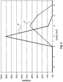
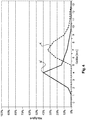
- the free-flowing carrier material can have a half-width of the particle size in a range of ⁇ 1.8 mm, in particular 2 mm, for example 2.3 mm, in particular 2.5 mm, the upper limit basically being freely selectable and, for example at ⁇ 6mm, approximately at ⁇ 4.5mm, for example at ⁇ 3mm.
- the generally known methods such as, for example, laser diffractometry, with which particle sizes ranging from a few nanometers to several millimeters can be determined.
- FWHM Full Width at Half Maximum
- a carrier material with such a comparatively inhomogeneous particle size distribution can lead to a significantly improved or homogenized melting of the carrier material.
- a carrier material in this embodiment a complete melting of the carrier material can be accelerated, which can make the process more economical.
- carriers can be provided which can have a particularly smooth and thus high-quality surface. For example, a corrugation of the carrier surface can be achieved with a wave depth in a range of 20-40 ⁇ m.
- the particle size distribution in this embodiment is in contrast to the requirements often known in the prior art, which just do not require inhomogeneity of the particle sizes, but where it is rather desirable to use highly homogeneous pourable starting materials.
- such carrier materials can be provided by milling or shredding raw material, for example, which can be realized in a cutting mill.
- a granulator with a screen of 6mm may be used to provide a substrate in this design.
- carrier materials can be provided which have a particularly suitable fine grain content.
- the fine grain fraction may range from> 0% by weight to ⁇ 50% by weight, for example from ⁇ 5% by weight to ⁇ 40% by weight, for example in a range from G 10% by weight to ⁇ 30% by weight, determined with a screen with 2mm mesh size, exhibit.
- the carrier materials may have particles with a size in a range of ⁇ 2 mm in one of the aforementioned ranges.
- comparatively large particles can be provided in the carrier material in addition to an aforementioned fine grain fraction.
- recycled materials can be used, as already indicated above.
- broke produced carrier plates can be supplied as a raw material of a reduction described above and then used as Rajermateriel.
- the manufacturing process can be particularly economical. Another advantage is that such recycling material is already adapted to the corresponding requirements, such as composition, or meets them. It may be provided that the crushed material of the rejects the conventional Susunarily used.
- a carrier material can be used which has a particularly suitable melt flow index (melt flow index, MFI).
- MFI melt flow index
- the MFI value can be determinable, for example, according to DIN 53 735 or ISO 1133.
- Particularly suitable values can be, for example, in a range of ⁇ 7.0 g / 10 min to ⁇ 9.0 g / 10 min.
- the abovementioned values are determined on the basis of the abovementioned standard, concretely used as measuring conditions being 10 kg / 190 ° C., an MFI value of ⁇ 8.0 g / 10 min to ⁇ 9.0 g / 10 min, for example of 8.5 g / 10min may be advantageous, or 21.6kg / 190 ° C, with an MFI value of ⁇ 7.5g / 10min to ⁇ 8.5g / 10min, for example, of 7.9g / 10min may be advantageous, the above values not restrictive.
- the carrier material may comprise hollow microspheres.
- Such additives can in particular cause the density of the carrier and thus of the panel produced can be significantly reduced, so that a particularly simple and cost-effective transport and also a particularly comfortable installation can be guaranteed.
- a stability of the panel produced can be ensured in particular by the insertion of hollow microspheres, which is not significantly reduced compared to a material without hollow microspheres.
- Micro hollow spheres can be understood in particular to mean structures which have a hollow base body and a size or a maximum diameter, which in the Micrometer range is.
- usable hollow spheres may have a diameter which is in the range of ⁇ 5 ⁇ m to ⁇ 100 ⁇ m, for example ⁇ 20 ⁇ m to ⁇ 50 ⁇ m.
- a material of the hollow microspheres is basically any material into consideration, such as glass or ceramic.
- due to the weight of plastics, such as the plastics used in the support material, for example PVC, PE or PP, may be advantageous, which may optionally be prevented, for example by suitable additives, from deforming during the manufacturing process.
- the band-like conveying means may be at least partially structured.
- structured conveying means it is possible to produce a carrier which is likewise structured and thus can have pores, for example, which can reflect a natural product to be sensed.
- the structuring or the pores can be realized in this embodiment in one step with the forming of the band-shaped carrier, so that a further step for the formation of the pores can be omitted.
- the introduced structure in that it is already present in the carrier and thus in the core of the panel, even with the highest stress be particularly stable and durable.
- the conveyor belts can also have a defined roughness, since such a venting can be improved in a shaping of the carrier.
- different roughness depths can be used for the upper and lower band, wherein the lower band can have a greater roughness depth than the upper band or band-like conveying means.
- the lower band and / or the upper band may have a roughness depth in a range of ⁇ 0 to ⁇ 25 ⁇ m.
- a sensor for checking the arrangement of the carrier material between the two belt-like conveying means may be provided.
- the sensor may detect the placement of the substrate on the lower conveyor.
- the sensor may have a feedback to the scattering units so as to be able to react immediately to a faulty application.
- the sensor can be shielded by appropriate fenders to prevent accidental leakage of X-rays.
- a cooling system can be provided to protect and extend the life of the sensor.
- a fiber material can be incorporated into the carrier.
- the fiber material can be incorporated into the carrier in process step b).
- a fiber material in particular as a fiber material web, be wound on a roll and unwound by means of a unwinding station for unwinding the fiber material and are guided between the two belt-like conveying means to insert the fiber material.
- a glass fiber fleece can be used.
- a carrier can be produced with a particularly high load-bearing capacity or stability, since the strength of the carrier can be significantly increased by the incorporated fiber material.
- the carrier can be particularly tailored in this embodiment, since, for example, by providing a plurality of scattering units, as explained above in detail, the carrier material, for example, above and below the web can be adjusted as desired. Furthermore, a still tailor-made solution can be made possible by the provision of a plurality of fibrous material webs, wherein the carrier material can in turn be variable or adaptable as desired.
- a temperature gradient can be set in method step c).
- a temperature gradient can be set along a conveying direction of the carrier material.
- this method step can enable a particularly high-quality product and also allow a particularly high line speed.
- a particularly rapid heating can be made possible, which allows a high line speed. This can be realized, for example, by a comparatively higher temperature in a first or front region in the conveying direction. In this case, too high a temperature effect on the carrier material can continue to be prevented, which can prevent damage and enable a particularly high quality.
- a degassing can be improved and accelerated upon heating of the support material, which in turn allows a high line speed and also can provide a particularly high stability and quality by preventing gas inclusions.
- This can be made possible in particular by a temperature gradient in a direction perpendicular to the conveying direction.
- the area below the carrier material can be heated higher than the area above the carrier material.
- a temperature gradient in a range of 50 ° C may be advantageous.
- method step c) can be carried out using two plate-like shaping devices.
- a particularly long processing time and shaping of the carrier take place even at high line speeds, which may allow a particularly defined forms of the carrier.
- the carrier material For in particular in this embodiment can be easily heated to a desired and necessary temperature even at high line speeds by a long contact time of the carrier material with the plate-like shaping devices, which can be heated accordingly, the carrier material become.
- the formation of temperature profiles can be made particularly simple and effective.
- process step d) can be carried out using an S-roll.
- an S-roll as a compression unit, desired compression can be enabled with a simple and inexpensive means defined even at high line speeds.
- the roller can be adjustable, for example, in the direction of the continuous carrier material.
- the S-roll for example, only comprise a roller which exerts a force only in combination with a counterforce by the belt tension of the conveyor.
- one or a plurality of counter-rollers may be provided, which apply the corresponding counterforce.
- an S-roll can be understood to mean a roll which is arranged such that the support circulates in an S-shaped manner, as is known to the person skilled in the art and described in detail below with reference to the figures.
- step e) The carrier is compressed in step e) by a factor of> 0% to ⁇ 7%, preferably> 0% to ⁇ 5%.
- method step e) can thus obtain a particularly smooth surface by means of a slight compression, since this method step can be adjusted substantially to the smoothing or to the setting of the surface quality.
- the entire structure of the press, in particular the dual-band press can be aligned with smoothing and there is no need to focus on excessive compression, which can produce a particularly good surface image even at high throughputs.
- the invention relates to a device for producing a decorated wall or floor panel, which is characterized in that the device comprises means for performing a method configured as described above.
- the device comprises means for performing a method configured as described above.
- the decor also corresponds to the desired imitation of a natural material, for example, in the areas of the profiling in a detailed manner.
- the print template used for printing in the area of the profiling of the panel can be distortion-compensated.
- Distortion compensation means in the context of the invention for example, for the exemplary case of application with a printing process, which is compensated by the deviation of the profiling from the surface plane of the carrier, for example at a chamfer flank, caused distortion of the printed image by adjusting the artwork to the deviation. It may be provided, for example, that the compensation of the distortion by means of adjustment of the pixel spacing, the pixel size and / or the ink application depending on the intended edge profile of the finished decorative panel.
- the triggering of the print head can be effected as a function of the distortion to be compensated, so that the print head is deflected beyond the profiled area, for example, and the color output is adapted to the profile.
- the joints to be provided in a final panel composite are milled into the carrier on the profile thus profiled
- Carrier at least the decorative layer is applied and the carrier is then divided at least in the profiled areas.
- the type of division such as, for example, sawing, laser cutting or water jet cutting, it can preferably be provided that the required cutting allowance in the introduced profile is taken into account.
- the plate-shaped carrier may comprise a material based on a WPC material or a PVC material.
- a WPC material or a PVC material.
- the device 10 comprises first two circumferential band-like conveying means 12, 14 which are guided in particular by deflection rollers 16 such that between them a receiving space 18 for receiving and processing a provided pourable, in particular granular carrier material 20, such as based on a plastic, such as PVC, or a wood-plastic composite material, such as wood and PP, PE or a block copolymer comprising PP and PE, forms.
- the conveying means 12, 14 may be at least partially made of polytetrafluoroethylene, for example coated therewith.
- the conveying means 12, 14 may be at least partially roughened or structured, in particular on their side facing the receiving space 18. Further, the conveying means 12, 14 may have a width in a range of about 1.5 m.
- the carrier material 20 it may be particularly advantageous that it has a half-width of the particle size in a range of ⁇ 1.8 mm, for example ⁇ 2 mm, in particular 2.3 mm, for example 2.5 mm, and thus a comparatively high inhomogeneity having the particle size.
- ⁇ 1.8 mm for example ⁇ 2 mm, in particular 2.3 mm, for example 2.5 mm
- the curves A and A 'respectively describe a particularly preferred carrier material 20 and the curves B and B' respectively describe a carrier material 20 which is basically also usable according to the invention and has a comparatively homogeneous particle size distribution.
- the carrier material 20 of the curves B and B 'obtained, for example, as extruder granulate has a half-width of approximately 1.2 (curve B) or 1.7 (curve B'), whereas the carrier material 20 produced, for example, by a granulator of the curves A and A 'has a half width of about 2.3 (curve A) and 2.7 (curve A').
- a discharge unit 22 is provided with one or a plurality of discharge heads 24, by means of which the carrier material 20 can be arranged on the lower conveying means 14.
- the discharge heads 24 may in this case comprise a funnel 25, which applies the carrier material 20 to corresponding scattering rollers 26, whereupon the carrier material 20 can be scattered onto the lower conveying means 14.
- a sensor for checking the arrangement of the carrier material 20 between two belt-like conveying means 12, 14 may be provided.
- the sensor may in particular be coupled to the discharge unit 22 in order to directly correct a potentially inaccurate filling of the receiving space 18.
- vibrators may also be provided. These can be approximately on the lower conveyor 14th act and thereby be arranged, for example, under the lower conveyor 14, so that the carrier material 20 is finely distributed.
- a device for introducing a fiber material into the receiving space 18 and thus be provided in the carrier can be designed like a belt and unwound from a roll.
- the fiber material may be arranged approximately between two discharge heads 24 in order, for example, to be able to arrange a different material above and below the fiber material.
- the fiber material can be introduced, for example, such that above and below the fiber material, a desired amount of support material 20 is located.
- a forming unit 28 is further provided, which is adapted to the carrier material 20 under the action of temperature or heat to fuse the carrier material 20 to form a web-shaped carrier 36 to shape.
- the molding unit 28 can have approximately two plate-like molding devices 30, 32, which can be heated by a heating device 34, for example by means of a thermal oil.
- the support material 20 may be heated until, depending on the melting point of the support material 20 or a part thereof, a temperature of, for example and depending on the material used, such as PVC or a WPV material, ⁇ 180 ° C to ⁇ 200 ° C has reached.
- the molding unit 28 or the molding devices 30, 32 can be heated, for example to a temperature of up to 250 ° C.
- a Be provided plurality of independently adjustable heating areas for example, the entire shaping devices 30, 32, which may have a length of several meters, may be heatable, or only part of them may be heatable.
- the molding unit 28 may in particular have a parallel gap, which may be formed by the plate-like molding devices 30, 32.
- an inlet mouth can be provided at the inlet through a conical shape to allow an improved inlet of the carrier material 20.
- the force acting on the carrier material 20 may be fed in a range from> 0 kg / m 2, up to ⁇ 1 kg / m 2.
- a uniform pressurization without the provision of a pressure profile or a pressure gradient can be provided.
- the lower former 32 is longer than the upper former 30 and also begins before the upper. It can thereby be achieved that processing only takes place when the carrier material 20 has already been melted or at least melted on and at least partially softened. As a result, a particularly defined shaping process can be made possible.
- the pressing device 38 may for example comprise an S-roll, which in detail in the FIG. 2 is shown.
- the S-roll can be moved substantially perpendicular to the surface of the carrier 36 and thus to the direction of travel of the carrier 36, as indicated by the arrow 58, so that the desired pressures can be particularly advantageous adjustable.
- the pressing device 38 may, for example, on the carrier 36 exert a pressure that may be in a range of ⁇ 1kg / m 2 to ⁇ 3kg / m 2 .
- the S-roll comprises a main roller 60, which acts on the web-shaped carrier 36.
- the belt tension can be sufficient as a back pressure, but it is preferred that at least one Counter-pressure roller 62 is provided.
- two pairs of calender rolls 64 and, optionally, deflection rolls 66 can also be provided, which can furthermore provide for a suitable strip tension.
- the main roller 60 may be wrapped by the sheet-shaped carrier 36 in a range of about 50% or more.
- the temperature of the carrier 36 further corresponds to an inlet to the pressing device 38, in particular the temperature present at the output from the molding unit 28.
- the carrier 36 is subsequently guided to a further pressing device 40.
- another heater 42 such as an IR heater, may be provided between the press devices 38, 40.
- this advantageously can be a two-belt press, which in particular can have steel belts 44, 46 and wherein the belts 44, 46 of the two-belt press can be guided by deflection rollers 48, 50.
- the deflection rollers 48, 50 can be heated, for example by means of a thermal oil heater and / or the rollers on the same side of the gap can be arranged approximately a distance in a range of ⁇ 1m to ⁇ 2m, for example 1.5m from each other, wherein the Bands 44, 46 may have a width in a range of about 1.5m.
- the carrier 20 located between the conveying means 12, 14 is guided between the deflection rollers 48, 50 and thus between the belts 44, 46, in particular steel belts.
- each pressing and / or heating means 52, 54 are provided on the carrier 36 opposite side of the bands 44, 46.
- These can both the conveyors 12, 14 and thus the carrier 36 both heat, as well as slightly compress.
- about an air heater may be provided and a plurality of rollers, which a enable intermittent pressing.
- a temperature in a range of up to 250 ° C act on the carrier 36.
- the temperature may be in a range from ⁇ 25 ° C to ⁇ 35 ° C above the melting temperature or softening temperature of the support material or a part thereof.
- such a pressure acts on the carrier 36 that the carrier 36 in method step e) by a factor of> 0% to ⁇ 7%, preferably ⁇ 5%, for example in a range of ⁇ 0,1mm to ⁇ 0, 2mm is compressed.
- the pressing and / or heating devices 52, 54 can occupy substantially the entire area between the deflection rollers 48, 50, or only a limited area along the conveying direction.
- the carrier After passing through the pressing device 40, the carrier may have a temperature in the range of approximately 190 ° C.
- the pressing device 40 may have a variable pressure profile, starting approximately with 6mm and ending with 4.1mm, or advantageously designed as an isochronous press.
- a cooling device 56 is arranged, through which the carrier can be cooled to a temperature which is for example in a range of ⁇ 35 ° C.
- the cooling device 56 may be based, for example, on a water cooling system and include a plurality of cooling zones, in order to allow a defined cooling using precisely customizable cooling programs.
- the length of the cooling zone can correspond to the effective length of the pressing device 40. After the cooling device 56 may still be provided another cooling belt.
- the carrier which may have about a final thickness in a range of ⁇ 3mm to ⁇ 5mm, for example, 4.1mm, immediately further treated be, or stored, such as a web-shaped carrier 36 or as an already isolated plate-shaped carrier.
Claims (11)
- Procédé de fabrication d'un panneau mural ou de sol décoré, présentant les étapes de procédé :a) de fourniture d'un matériau de support (20) apte à être déversé, notamment un granulat,b) de disposition du matériau de support (20) entre deux moyens de transport de type bandes (12, 14),c) de moulage du matériau de support (20) moyennant la formation d'un support (36) en forme de bande sous l'effet de la température,d) de compression du support (36),e) de traitement du support (36) sous l'effet de la température et de la pression moyennant l'emploi d'une presse à deux bandes,f) de refroidissement du support (36),g) éventuellement, d'application d'un fond de décor sur au moins une zone partielle du support (36) ;h) d'application d'un décor reproduisant un modèle de décor sur au moins une zone partielle du support (36),i) d'application d'une couche de protection sur au moins une zone partielle du décor,j) éventuellement, de structuration de la couche de protection en vue de l'incorporation de pores, et/ou de la zone de bordure du support pour la formation d'éléments de liaison, etk) éventuellement, de traitement du support (36) pour une décharge électrostatique avant l'une des étapes de procédé précédemment citées, oùle support est comprimé d'un facteur de >0% à ≤7%, de préférence ≤ 5%, lors de l'étape de procédé e).
- Procédé selon la revendication 1, caractérisé en ce qu'un matériau de support (20) à base d'une matière plastique ou d'une matière composite bois-matière plastique est mis à disposition.
- Procédé selon la revendication 2, caractérisé en ce qu'un matériau de support (20) à base d'une matière composite bois-plastique WPC, présentant du bois et du polyéthylène, du bois et du polypropylène ou du bois et un copolymère de polyéthylène et de polypropylène est mis à disposition.
- Procédé selon la revendication 2, caractérisé en ce qu'un matériau de support (20) à base d'une matière PVC est mis à disposition.
- Procédé selon l'une des revendications précédentes, caractérisé en ce que la matériau de support présente du bois et/ou de la craie avec une taille de particules entre ≥ 0 et ≤ 600 µm et une distribution des particules D50 ≥ 400 µm, de préférence, une distribution de particules D10 ≤ 400 µm.
- Procédé selon l'une des revendications précédentes, caractérisé en ce que le matériau de support (20) présente des microbilles creuses.
- Procédé selon l'une des revendications précédentes, caractérisé en ce que le matériau de support apte à être déversé présente une largeur à mi-hauteur de la taille des particules dans une plage de ≥ 1,8 mm, notamment de ≥ 2,0 mm.
- Procédé selon l'une des revendications précédentes, caractérisé en ce qu'un matériau fibreux, notamment une bande de matière fibreuse, est incorporée dans le support (36).
- Procédé selon l'une des revendications précédentes, caractérisé en ce qu'un gradient de température est réglé dans l'étape de procédé c).
- Procédé selon l'une des revendications précédentes, caractérisé en ce que l'étape de procédé d) est effectuée moyennant l'emploi d'un rouleau S.
- Dispositif de fabrication d'un panneau mural ou de sol décoré, présentant- un moyen de transport inférieur (12) de type bande et pouvant être parcouru circonférentiellement et un moyen de transport supérieur (14) de type bande et pouvant être parcouru circonférentiellement disposé à un espace défini par rapport au moyen de transport inférieur (12) ;- un ou une multitude de têtes de prélèvement (24) pour le prélèvement et le dépôt du matériau de support (20) sur le moyen de transport inférieur (14) ;- une unité de mise en forme (28), laquelle est conçue pour faire fondre le matériau de support (20) sous l'effet de la température moyennant la formation d'un support (36) en forme de bandes ;- un dispositif de presse (38) pour la compression du support (36) ;- une presse à deux bandes pour le traitement du support (36) sous l'effet de la température et de la pression, où la presse à deux bandes est conçue pour comprimer le support d'un facteur de ≥ 0% à ≤ 7%, de préférence ≤ 5% ;- un dispositif pour l'application d'un décor reproduisant un modèle de décor sur au moins une zone partielle du support (36) ; et- un dispositif pour l'application d'une couche de protection sur au moins une zone partielle du décor.
Priority Applications (3)
| Application Number | Priority Date | Filing Date | Title |
|---|---|---|---|
| EP14739847.3A EP3024669B1 (fr) | 2013-07-22 | 2014-07-18 | Procédé de fabrication d'un panneau mural et de sol décoré |
| PL14739847T PL3024669T3 (pl) | 2013-07-22 | 2014-07-18 | Sposób wytwarzania dekorowanego panelu ściennego lub podłogowego |
| EP18172580.5A EP3401115B1 (fr) | 2013-07-22 | 2014-07-18 | Procédé de fabrication d'un panneau mural ou de sol décoré |
Applications Claiming Priority (4)
| Application Number | Priority Date | Filing Date | Title |
|---|---|---|---|
| EP13177453.1A EP2829415A1 (fr) | 2013-07-22 | 2013-07-22 | Procédé de fabrication d'un panneau mural et de sol décoré |
| DE102013108671 | 2013-08-09 | ||
| EP14739847.3A EP3024669B1 (fr) | 2013-07-22 | 2014-07-18 | Procédé de fabrication d'un panneau mural et de sol décoré |
| PCT/EP2014/065509 WO2015011049A1 (fr) | 2013-07-22 | 2014-07-18 | Procédé de production d'un panneau mural ou de sol décoré |
Related Child Applications (2)
| Application Number | Title | Priority Date | Filing Date |
|---|---|---|---|
| EP18172580.5A Division EP3401115B1 (fr) | 2013-07-22 | 2014-07-18 | Procédé de fabrication d'un panneau mural ou de sol décoré |
| EP18172580.5A Division-Into EP3401115B1 (fr) | 2013-07-22 | 2014-07-18 | Procédé de fabrication d'un panneau mural ou de sol décoré |
Publications (2)
| Publication Number | Publication Date |
|---|---|
| EP3024669A1 EP3024669A1 (fr) | 2016-06-01 |
| EP3024669B1 true EP3024669B1 (fr) | 2018-06-27 |
Family
ID=51210494
Family Applications (2)
| Application Number | Title | Priority Date | Filing Date |
|---|---|---|---|
| EP14739847.3A Active EP3024669B1 (fr) | 2013-07-22 | 2014-07-18 | Procédé de fabrication d'un panneau mural et de sol décoré |
| EP18172580.5A Active EP3401115B1 (fr) | 2013-07-22 | 2014-07-18 | Procédé de fabrication d'un panneau mural ou de sol décoré |
Family Applications After (1)
| Application Number | Title | Priority Date | Filing Date |
|---|---|---|---|
| EP18172580.5A Active EP3401115B1 (fr) | 2013-07-22 | 2014-07-18 | Procédé de fabrication d'un panneau mural ou de sol décoré |
Country Status (17)
| Country | Link |
|---|---|
| US (1) | US10059072B2 (fr) |
| EP (2) | EP3024669B1 (fr) |
| JP (1) | JP6333375B2 (fr) |
| KR (2) | KR20180028543A (fr) |
| CN (1) | CN105307869B (fr) |
| AU (1) | AU2014295241A1 (fr) |
| CA (1) | CA2912978C (fr) |
| CL (1) | CL2015003750A1 (fr) |
| ES (1) | ES2687372T3 (fr) |
| MX (1) | MX366767B (fr) |
| MY (1) | MY177467A (fr) |
| PL (1) | PL3024669T3 (fr) |
| PT (1) | PT3024669T (fr) |
| RU (1) | RU2635043C2 (fr) |
| TR (1) | TR201812933T4 (fr) |
| UA (1) | UA115101C2 (fr) |
| WO (1) | WO2015011049A1 (fr) |
Families Citing this family (29)
| Publication number | Priority date | Publication date | Assignee | Title |
|---|---|---|---|---|
| BE1020722A3 (nl) | 2012-06-01 | 2014-04-01 | Unilin Bvba | Paneel voor het vormen van een vloerbekleding en werkwijze voor het vervaardigen van dergelijke panelen. |
| RU2635043C2 (ru) | 2013-07-22 | 2017-11-08 | Акцента Панееле + Профиле Гмбх | Способ получения декоративной стеновой или напольной панели |
| PL3323628T3 (pl) | 2014-02-25 | 2022-10-10 | Akzenta Paneele + Profile Gmbh | Sposób wytwarzania paneli dekoracyjnych |
| EP3126145B1 (fr) | 2014-03-31 | 2020-08-26 | Ceraloc Innovation AB | Planches et panneaux composites |
| EP2942208A1 (fr) | 2014-05-09 | 2015-11-11 | Akzenta Paneele + Profile GmbH | Procédé de fabrication d'un panneau mural ou de sol décoré |
| DE102015204142A1 (de) * | 2015-03-09 | 2016-09-15 | Bayerische Motoren Werke Aktiengesellschaft | Verfahren zur Herstellung von faserverstärkten Kunststoffbauteilen |
| EP3088204B1 (fr) * | 2015-04-28 | 2020-01-08 | Akzenta Paneele + Profile GmbH | Procédé de fabrication d'un panneau mural ou de sol décoré |
| EP3088205A1 (fr) * | 2015-04-28 | 2016-11-02 | Akzenta Paneele + Profile GmbH | Procédé de fabrication d'un panneau mural ou de sol décoré |
| PL3132945T3 (pl) * | 2015-08-19 | 2020-03-31 | Akzenta Paneele + Profile Gmbh | Sposób wytwarzania dekorowanego panelu ściennego lub podłogowego |
| BE1023446B1 (nl) | 2015-09-14 | 2017-03-22 | Ivc N.V. | Werkwijze voor het vervaardigen van vloerpanelen en vloerpaneel voor het vormen van een vloerbekleding |
| EP3147135B1 (fr) * | 2015-09-24 | 2020-11-18 | Akzenta Paneele + Profile GmbH | Procede de fabrication d'un panneau mural ou de sol decore |
| DE102016100608A1 (de) | 2016-01-14 | 2017-07-20 | Karl-Heinz Scholz | Bauelement in Plattenform, insbesondere Bodenbelags-Paneel, sowie Bodenbelag unter Verwendung dieser Bauelemente nebst Verfahren zu deren Anordnung |
| BE1023817B1 (nl) | 2016-01-15 | 2017-08-01 | Unilin Bvba | Vloerpaneel voor het vormen van een vloerbekleding, en substraat voor een paneel |
| PT3246175T (pt) | 2016-05-20 | 2018-10-22 | Flooring Technologies Ltd | Processo para a produção de uma placa de derivados de madeira resistente à abrasão e linha de produção para a mesma |
| PL3500535T3 (pl) * | 2016-08-19 | 2020-12-14 | Xylo Technologies Ag | Powlekany panel i sposób wytwarzania powlekanego panelu |
| KR102493210B1 (ko) | 2016-11-08 | 2023-01-27 | 우디오 오와이 | 압축된 물품 및 이의 제조 방법 |
| RS61736B1 (sr) | 2017-02-03 | 2021-05-31 | Xylo Tech Ag | Pvc-plastični panel |
| CN106863538B (zh) * | 2017-02-15 | 2018-07-31 | 亚联机械股份有限公司 | 一种改善压制板横向结构均匀性的连续式压制方法及装置 |
| EP3385046A1 (fr) * | 2017-04-07 | 2018-10-10 | Omya International AG | Planches en bois décoratives revêtues en ligne |
| CA3028082A1 (fr) * | 2018-12-19 | 2020-06-19 | Gordon Neustaeter | Systeme de tablier et procede d`installation |
| BE1026957B1 (nl) | 2019-01-09 | 2020-08-14 | Ivc Bvba | Methode voor het vervaardigen van een vloer- of wandpaneel |
| PT3686028T (pt) | 2019-01-22 | 2021-05-05 | Flooring Technologies Ltd | Processo para o fabrico de um painel de derivados de madeira resistente à abrasão |
| EP3686008B1 (fr) * | 2019-01-23 | 2021-06-23 | Flooring Technologies Ltd. | Procédé de fabrication d'un panneau multicouche résistant à l'abrasion et à l'eau et panneau fabriqué selon ledit procédé |
| CN110450295A (zh) * | 2019-08-15 | 2019-11-15 | 中南林业科技大学 | 一种石塑地板基材物料混炼系统及方法 |
| EP4314439A1 (fr) * | 2021-03-30 | 2024-02-07 | Ceraloc Innovation AB | Procédé et ensemble de fabrication d'un élément de planche comprenant un matériau recyclé |
| NL2029345B1 (en) * | 2021-10-07 | 2023-04-20 | Champion Link Int Corp | Decorative panel |
| CN115946415A (zh) * | 2021-10-07 | 2023-04-11 | 财纳福诺木业(中国)有限公司 | 一种装饰板及生产这种装饰板的方法 |
| CN114133182B (zh) * | 2021-12-04 | 2022-10-11 | 广东盈辉建设工程有限公司 | 一种节能保温复合墙体及其施工方法 |
| TWI805220B (zh) * | 2022-02-10 | 2023-06-11 | 林正雄 | 石塑地板及其製備方法 |
Citations (11)
| Publication number | Priority date | Publication date | Assignee | Title |
|---|---|---|---|---|
| GB994894A (en) | 1961-01-28 | 1965-06-10 | Shigenari Soda | Improvements relating to the treatment of resinous material |
| DE2600144A1 (de) | 1975-01-06 | 1976-07-15 | Hazelett Strip Casting Corp | Verfahren und vorrichtung zum kontinuierlichen formen von gegenstaenden mit dreidimensionalen mustern und oberflaechenstrukturen aus thermoplastischen polymeren werkstoffen |
| US4826560A (en) | 1985-08-24 | 1989-05-02 | Kurt Held | Device for continuous production of thermoplastic webs |
| DE19751516A1 (de) | 1997-11-21 | 1999-05-27 | Schilling Knobel Gmbh | Verfahren zur Herstellung von thermofixierten Bahnen aus thermoplastischen Polymer-Materialteilchen |
| WO2009065769A2 (fr) | 2007-11-19 | 2009-05-28 | Välinge Innovation Belgium BVBA | Panneaux à base de fibres présentant une surface de résistance à l'usure |
| DE102007063261A1 (de) | 2007-12-17 | 2009-06-18 | Thermofix Technology Center Gmbh | Verfahren zur kontinuierlichen Herstellung von bahn- oder plattenförmigen Belägen sowie Anlage hierzu |
| US20090202810A1 (en) | 2008-02-13 | 2009-08-13 | Microposite, Inc. | Process and Machine for Manufacturing Lap Siding and the Product Made Thereby |
| WO2012016916A1 (fr) | 2010-08-03 | 2012-02-09 | Sandvik Materials Technology Deutschland Gmbh | Presse à double bande et procédé de fabrication d'un produit en forme de plaque au moyen d'une presse à double bande |
| US20120183727A1 (en) | 2011-01-19 | 2012-07-19 | TPS TechnoPartner Samtronic GmbH | Polymer-bound web as well as method for its production |
| WO2013179260A1 (fr) | 2012-06-01 | 2013-12-05 | Unilin, Bvba | Panneau de formation d'un revêtement de sol, procédé de fabrication dudit panneau et granulat appliqué avec celui-ci |
| WO2015011049A1 (fr) | 2013-07-22 | 2015-01-29 | Akzenta Paneele + Profile Gmbh | Procédé de production d'un panneau mural ou de sol décoré |
Family Cites Families (24)
| Publication number | Priority date | Publication date | Assignee | Title |
|---|---|---|---|---|
| DE2420029C3 (de) * | 1974-04-25 | 1978-11-23 | Hermann Berstorff Maschinenbau Gmbh, 3000 Hannover | Preßeinrichtung zum kontinuierlichen Herstellen von Spanplatten, Faserplatten o.dgl |
| ES475440A2 (es) | 1978-11-27 | 1979-05-01 | Pillado Perez Adolfo | Perfeccionamientos introducidos en el objeto de la patente principal por sistema de revestimiento para suelos y paredes |
| GB8519297D0 (en) * | 1985-07-31 | 1985-09-04 | Smith Tech Dev | Laminate production |
| JPH09314712A (ja) * | 1996-05-27 | 1997-12-09 | Mitsui Petrochem Ind Ltd | 複合パネル |
| KR100219734B1 (ko) * | 1996-07-18 | 1999-09-01 | 이정국 | 합판대체용 열가소성고분자 복합패널 |
| SE512143C2 (sv) * | 1997-05-06 | 2000-01-31 | Perstorp Ab | Förfarande för framställning av dekorativt laminat och användning därav |
| JPH11279416A (ja) * | 1998-03-30 | 1999-10-12 | Nippon Zeon Co Ltd | 熱可塑性樹脂組成物 |
| DE10001148A1 (de) * | 2000-01-13 | 2001-07-26 | Dlw Ag | Flächengebilde mit strukturierter Oberfläche und Verfahren zu dessen Herstellung |
| US6440538B1 (en) | 2000-04-03 | 2002-08-27 | Lg Chem Ltd. | Abrasion resistant laminate |
| US7037865B1 (en) * | 2000-08-08 | 2006-05-02 | Moldite, Inc. | Composite materials |
| US6638636B2 (en) * | 2001-08-28 | 2003-10-28 | Kimberly-Clark Worldwide, Inc. | Breathable multilayer films with breakable skin layers |
| UA79054C2 (uk) * | 2003-10-01 | 2007-05-10 | Фрітц Еггер Гмбх Унд Ко. | Формувальна маса, спосіб виготовлення формованого виробу із формувальної маси і формований виріб |
| JP2006142496A (ja) * | 2004-11-16 | 2006-06-08 | Toppan Printing Co Ltd | 鏡面耐シガレット性化粧シートおよび化粧板 |
| DE202006020503U1 (de) * | 2006-10-19 | 2008-10-09 | Basf Se | Leichte Holzwerkstoffe |
| US8956714B2 (en) | 2007-04-10 | 2015-02-17 | Spanolux N.V.-Div. Balterio | Method and apparatus for manufacturing laminate floor panels comprising a core containing wood/plastic composite, as well as such panels |
| JP5361217B2 (ja) * | 2008-02-29 | 2013-12-04 | 株式会社Adeka | 耐候性の改善された木質系合成樹脂組成物およびその成形体 |
| BE1018680A5 (nl) | 2008-12-19 | 2011-06-07 | Flooring Ind Ltd Sarl | Werkwijzen voor het vervaardigen van panelen en paneel hierbij bekomen. |
| JP5161123B2 (ja) * | 2009-01-16 | 2013-03-13 | 古河機械金属株式会社 | 複合木材の製造方法 |
| IT1396904B1 (it) * | 2009-04-22 | 2012-12-20 | Nasatti | Procedimento e impianto per la fabbricazione di carte decorative e/o pannelli da pavimentazione o rivestimento di mobili, pareti, eccetera |
| WO2011085306A1 (fr) * | 2010-01-11 | 2011-07-14 | Mannington Mills, Inc. | Revêtement de sol à conception verrouillée |
| EP2402155A1 (fr) * | 2010-06-30 | 2012-01-04 | Spanolux N.V. Div. Balterio | Panneau comprenant une couche composée polymère et une couche de renfort |
| DE102011001807B4 (de) * | 2011-04-05 | 2024-02-08 | Guido Schulte | Bodenpaneel und Verfahren zu deren Herstellung |
| PL2616250T3 (pl) * | 2010-09-14 | 2016-12-30 | Element wykończeniowy do wnętrz do wykonywania pokryć oraz sposób wytwarzania elementu wykończeniowego do wnętrz | |
| CN104136179B (zh) * | 2011-12-23 | 2016-10-12 | 巴斯夫欧洲公司 | 在外层具有木质纤维素纤维且在芯中存在发泡塑料颗粒的木质纤维素材料及其方法和用途 |
-
2014
- 2014-07-18 RU RU2016105441A patent/RU2635043C2/ru active
- 2014-07-18 WO PCT/EP2014/065509 patent/WO2015011049A1/fr active Application Filing
- 2014-07-18 KR KR1020187006238A patent/KR20180028543A/ko not_active Application Discontinuation
- 2014-07-18 PT PT14739847T patent/PT3024669T/pt unknown
- 2014-07-18 EP EP14739847.3A patent/EP3024669B1/fr active Active
- 2014-07-18 ES ES14739847.3T patent/ES2687372T3/es active Active
- 2014-07-18 MY MYPI2015704445A patent/MY177467A/en unknown
- 2014-07-18 CN CN201480035168.4A patent/CN105307869B/zh active Active
- 2014-07-18 PL PL14739847T patent/PL3024669T3/pl unknown
- 2014-07-18 TR TR2018/12933T patent/TR201812933T4/tr unknown
- 2014-07-18 EP EP18172580.5A patent/EP3401115B1/fr active Active
- 2014-07-18 CA CA2912978A patent/CA2912978C/fr active Active
- 2014-07-18 AU AU2014295241A patent/AU2014295241A1/en not_active Abandoned
- 2014-07-18 KR KR1020167002249A patent/KR102095082B1/ko active IP Right Grant
- 2014-07-18 MX MX2015017824A patent/MX366767B/es active IP Right Grant
- 2014-07-18 UA UAA201601637A patent/UA115101C2/uk unknown
- 2014-07-18 JP JP2016528463A patent/JP6333375B2/ja active Active
- 2014-07-18 US US14/419,798 patent/US10059072B2/en active Active
-
2015
- 2015-12-29 CL CL2015003750A patent/CL2015003750A1/es unknown
Patent Citations (15)
| Publication number | Priority date | Publication date | Assignee | Title |
|---|---|---|---|---|
| GB994894A (en) | 1961-01-28 | 1965-06-10 | Shigenari Soda | Improvements relating to the treatment of resinous material |
| DE2600144A1 (de) | 1975-01-06 | 1976-07-15 | Hazelett Strip Casting Corp | Verfahren und vorrichtung zum kontinuierlichen formen von gegenstaenden mit dreidimensionalen mustern und oberflaechenstrukturen aus thermoplastischen polymeren werkstoffen |
| US4826560A (en) | 1985-08-24 | 1989-05-02 | Kurt Held | Device for continuous production of thermoplastic webs |
| US4844766A (en) | 1985-08-24 | 1989-07-04 | Kurt Held | Process for continuous production of termoplastic webs |
| DE19751516A1 (de) | 1997-11-21 | 1999-05-27 | Schilling Knobel Gmbh | Verfahren zur Herstellung von thermofixierten Bahnen aus thermoplastischen Polymer-Materialteilchen |
| US6217700B1 (en) | 1997-11-21 | 2001-04-17 | Schilling-Knobel Gmbh | Method of and apparatus for manufacturing thermoset webs of thermoplastic polymer material particles |
| WO2009065769A2 (fr) | 2007-11-19 | 2009-05-28 | Välinge Innovation Belgium BVBA | Panneaux à base de fibres présentant une surface de résistance à l'usure |
| DE102007063261A1 (de) | 2007-12-17 | 2009-06-18 | Thermofix Technology Center Gmbh | Verfahren zur kontinuierlichen Herstellung von bahn- oder plattenförmigen Belägen sowie Anlage hierzu |
| US20090202810A1 (en) | 2008-02-13 | 2009-08-13 | Microposite, Inc. | Process and Machine for Manufacturing Lap Siding and the Product Made Thereby |
| WO2012016916A1 (fr) | 2010-08-03 | 2012-02-09 | Sandvik Materials Technology Deutschland Gmbh | Presse à double bande et procédé de fabrication d'un produit en forme de plaque au moyen d'une presse à double bande |
| US20130147090A1 (en) | 2010-08-03 | 2013-06-13 | Hans-Kurt Schromm | Double belt press and method for producing a plate-like product using a double belt press |
| US20120183727A1 (en) | 2011-01-19 | 2012-07-19 | TPS TechnoPartner Samtronic GmbH | Polymer-bound web as well as method for its production |
| WO2013179260A1 (fr) | 2012-06-01 | 2013-12-05 | Unilin, Bvba | Panneau de formation d'un revêtement de sol, procédé de fabrication dudit panneau et granulat appliqué avec celui-ci |
| WO2013179261A1 (fr) | 2012-06-01 | 2013-12-05 | Unilin, Bvba | Panneau permettant de former un revêtement de sol et procédé de fabrication desdits panneaux |
| WO2015011049A1 (fr) | 2013-07-22 | 2015-01-29 | Akzenta Paneele + Profile Gmbh | Procédé de production d'un panneau mural ou de sol décoré |
Non-Patent Citations (16)
| Title |
|---|
| "Advanced Technology for laminating and embossing solutions", PRÄSENTATION FIRMA OLBRICH |
| "Die Stärke von Sandvik: Erfahren - flexible - führend und Zuverlässig", NEWS & INFOLETTER SANDVIK, May 2006 (2006-05-01), pages 1 - 12, XP055601538 |
| "Double Belt Press Technology", HANDOUT ZUR PRÄSENTATION FIRMA TPS, 3 May 2012 (2012-05-03) |
| "Double-Belt Press Technology, Scattering Units", TPS GMBH, 26 June 2012 (2012-06-26), pages 1 - 22, XP055581908 |
| "Sandvik Stahlbandanlagen zum Pressen, Laminieren und Film-/Schichtgiessen", SANDVIK, February 2011 (2011-02-01), pages 1 - 12, XP055602358 |
| "Sandvik steel belt systems for pressing, lamination and casting", SANDVIK, February 2011 (2011-02-01), pages 1 - 12 |
| "Sandvik steel belt systems for pressing, lamination and casting", SANDVIK, February 2011 (2011-02-01), pages 1 - 12, XP055584021 |
| "Steel Belts for conveying and processing", SANDVIK MATERIALS TECHNOLOGY, May 2007 (2007-05-01), pages 6pp, XP055601534 |
| "Technology for a sustainable future", TPS, September 2011 (2011-09-01), pages 8PP, XP055601546 |
| "The innovative hybrid press with teflon and steel belts: 'CombiPress", TPS, 1 March 2011 (2011-03-01), pages 1 - 6, XP055581926 |
| "The innovative hybrid press with Teflon and Steel belts: 'TS-CombiPress", TPS, December 2010 (2010-12-01), pages 1 - 6, XP055601541 |
| ADVANCED TECHNOLOGY FOR LAMINATING AND EMBOSSING SOLUTIONS |
| KAREN WOOD: "Microspheres: Fillers Filled With Possibilities", COMPOSITES WORLD, 4 January 2008 (2008-01-04), XP055581930 |
| MARKED-UP DRAWING FROM E9 |
| SANDVIK: "The innovative Hybrid Press with Teflon0and Steel belts: Combipress", TPS GMBH, March 2011 (2011-03-01), XP055581926 |
| THOMAS KLENCK: "How Vinyl Flooring is Made", POPULAR MECHANICS, December 2002 (2002-12-01), pages 121 - 122, XP055581918 |
Also Published As
| Publication number | Publication date |
|---|---|
| EP3024669A1 (fr) | 2016-06-01 |
| ES2687372T3 (es) | 2018-10-24 |
| EP3401115A1 (fr) | 2018-11-14 |
| KR102095082B1 (ko) | 2020-03-30 |
| UA115101C2 (uk) | 2017-09-11 |
| PL3024669T3 (pl) | 2018-12-31 |
| MY177467A (en) | 2020-09-16 |
| JP6333375B2 (ja) | 2018-05-30 |
| RU2635043C2 (ru) | 2017-11-08 |
| MX2015017824A (es) | 2016-04-15 |
| CN105307869A (zh) | 2016-02-03 |
| US10059072B2 (en) | 2018-08-28 |
| WO2015011049A1 (fr) | 2015-01-29 |
| MX366767B (es) | 2019-07-22 |
| CA2912978C (fr) | 2018-01-02 |
| KR20180028543A (ko) | 2018-03-16 |
| US20160136913A1 (en) | 2016-05-19 |
| JP2016533444A (ja) | 2016-10-27 |
| AU2014295241A1 (en) | 2016-02-11 |
| RU2016105441A (ru) | 2017-08-29 |
| KR20160033710A (ko) | 2016-03-28 |
| EP3401115B1 (fr) | 2023-06-07 |
| CA2912978A1 (fr) | 2015-01-29 |
| CL2015003750A1 (es) | 2016-08-05 |
| TR201812933T4 (tr) | 2018-09-21 |
| CN105307869B (zh) | 2019-01-18 |
| PT3024669T (pt) | 2018-10-19 |
Similar Documents
| Publication | Publication Date | Title |
|---|---|---|
| EP3024669B1 (fr) | Procédé de fabrication d'un panneau mural et de sol décoré | |
| EP3140129B1 (fr) | Procédé de fabrication d'un panneau mural ou de sol décoré | |
| EP2829415A1 (fr) | Procédé de fabrication d'un panneau mural et de sol décoré | |
| EP3178652B1 (fr) | Panneau de decoration et son procede de fabrication | |
| EP3578384B1 (fr) | Matériau porteur à base d'une composition de matière plastique et d'une composition de matière solide minérales pour panneaux muraux ou de sol décorés | |
| EP3147135B1 (fr) | Procede de fabrication d'un panneau mural ou de sol decore | |
| EP2730429B1 (fr) | Procédé de fabrication d'un panneau mural ou de sol décoré | |
| EP2930031B9 (fr) | Panneau décoratif en composite bois-plastique (WPC) doté d'un bord profilé peu poreuse et son procédé de fabrication | |
| EP2739487A1 (fr) | Procédé de fabrication d'un panneau décoré mural, pour plafond ou plancher | |
| EP2909038A1 (fr) | Procédé de fabrication d'un panneau mural ou de sol décoré | |
| EP3132945B1 (fr) | Procede de fabrication d'un panneau mural ou de sol decore | |
| EP3088204B1 (fr) | Procédé de fabrication d'un panneau mural ou de sol décoré | |
| WO2021115653A1 (fr) | Méthode et dispositif de production d'un panneau décoratif pour un mur ou pour un sol | |
| DE102018119766B4 (de) | Multilaminares Kunststoffträgermaterial, Verfahren zu dessen Herstellung und Dekorpaneel | |
| EP3088205A1 (fr) | Procédé de fabrication d'un panneau mural ou de sol décoré | |
| EP3543034A1 (fr) | Plaque porteuse pour un panneau de paroi, de sol ou de plafond directement imprimés | |
| EP3536517A1 (fr) | Matériau support à base de minéraux pour panneaux muraux ou de plancher décorés |
Legal Events
| Date | Code | Title | Description |
|---|---|---|---|
| PUAI | Public reference made under article 153(3) epc to a published international application that has entered the european phase |
Free format text: ORIGINAL CODE: 0009012 |
|
| 17P | Request for examination filed |
Effective date: 20151117 |
|
| AK | Designated contracting states |
Kind code of ref document: A1 Designated state(s): AL AT BE BG CH CY CZ DE DK EE ES FI FR GB GR HR HU IE IS IT LI LT LU LV MC MK MT NL NO PL PT RO RS SE SI SK SM TR |
|
| AX | Request for extension of the european patent |
Extension state: BA ME |
|
| DAX | Request for extension of the european patent (deleted) | ||
| STAA | Information on the status of an ep patent application or granted ep patent |
Free format text: STATUS: EXAMINATION IS IN PROGRESS |
|
| 17Q | First examination report despatched |
Effective date: 20170629 |
|
| GRAP | Despatch of communication of intention to grant a patent |
Free format text: ORIGINAL CODE: EPIDOSNIGR1 |
|
| STAA | Information on the status of an ep patent application or granted ep patent |
Free format text: STATUS: GRANT OF PATENT IS INTENDED |
|
| INTG | Intention to grant announced |
Effective date: 20180124 |
|
| GRAS | Grant fee paid |
Free format text: ORIGINAL CODE: EPIDOSNIGR3 |
|
| GRAA | (expected) grant |
Free format text: ORIGINAL CODE: 0009210 |
|
| STAA | Information on the status of an ep patent application or granted ep patent |
Free format text: STATUS: THE PATENT HAS BEEN GRANTED |
|
| AK | Designated contracting states |
Kind code of ref document: B1 Designated state(s): AL AT BE BG CH CY CZ DE DK EE ES FI FR GB GR HR HU IE IS IT LI LT LU LV MC MK MT NL NO PL PT RO RS SE SI SK SM TR |
|
| REG | Reference to a national code |
Ref country code: GB Ref legal event code: FG4D Free format text: NOT ENGLISH |
|
| REG | Reference to a national code |
Ref country code: AT Ref legal event code: REF Ref document number: 1011962 Country of ref document: AT Kind code of ref document: T Effective date: 20180715 |
|
| REG | Reference to a national code |
Ref country code: DE Ref legal event code: R096 Ref document number: 502014008669 Country of ref document: DE |
|
| REG | Reference to a national code |
Ref country code: IE Ref legal event code: FG4D Free format text: LANGUAGE OF EP DOCUMENT: GERMAN |
|
| REG | Reference to a national code |
Ref country code: FR Ref legal event code: PLFP Year of fee payment: 5 |
|
| REG | Reference to a national code |
Ref country code: NL Ref legal event code: FP |
|
| REG | Reference to a national code |
Ref country code: PT Ref legal event code: SC4A Ref document number: 3024669 Country of ref document: PT Date of ref document: 20181019 Kind code of ref document: T Free format text: AVAILABILITY OF NATIONAL TRANSLATION Effective date: 20180912 |
|
| REG | Reference to a national code |
Ref country code: ES Ref legal event code: FG2A Ref document number: 2687372 Country of ref document: ES Kind code of ref document: T3 Effective date: 20181024 |
|
| PG25 | Lapsed in a contracting state [announced via postgrant information from national office to epo] |
Ref country code: BG Free format text: LAPSE BECAUSE OF FAILURE TO SUBMIT A TRANSLATION OF THE DESCRIPTION OR TO PAY THE FEE WITHIN THE PRESCRIBED TIME-LIMIT Effective date: 20180927 Ref country code: SE Free format text: LAPSE BECAUSE OF FAILURE TO SUBMIT A TRANSLATION OF THE DESCRIPTION OR TO PAY THE FEE WITHIN THE PRESCRIBED TIME-LIMIT Effective date: 20180627 Ref country code: LT Free format text: LAPSE BECAUSE OF FAILURE TO SUBMIT A TRANSLATION OF THE DESCRIPTION OR TO PAY THE FEE WITHIN THE PRESCRIBED TIME-LIMIT Effective date: 20180627 Ref country code: FI Free format text: LAPSE BECAUSE OF FAILURE TO SUBMIT A TRANSLATION OF THE DESCRIPTION OR TO PAY THE FEE WITHIN THE PRESCRIBED TIME-LIMIT Effective date: 20180627 Ref country code: NO Free format text: LAPSE BECAUSE OF FAILURE TO SUBMIT A TRANSLATION OF THE DESCRIPTION OR TO PAY THE FEE WITHIN THE PRESCRIBED TIME-LIMIT Effective date: 20180927 |
|
| REG | Reference to a national code |
Ref country code: LT Ref legal event code: MG4D |
|
| PG25 | Lapsed in a contracting state [announced via postgrant information from national office to epo] |
Ref country code: HR Free format text: LAPSE BECAUSE OF FAILURE TO SUBMIT A TRANSLATION OF THE DESCRIPTION OR TO PAY THE FEE WITHIN THE PRESCRIBED TIME-LIMIT Effective date: 20180627 Ref country code: GR Free format text: LAPSE BECAUSE OF FAILURE TO SUBMIT A TRANSLATION OF THE DESCRIPTION OR TO PAY THE FEE WITHIN THE PRESCRIBED TIME-LIMIT Effective date: 20180928 Ref country code: RS Free format text: LAPSE BECAUSE OF FAILURE TO SUBMIT A TRANSLATION OF THE DESCRIPTION OR TO PAY THE FEE WITHIN THE PRESCRIBED TIME-LIMIT Effective date: 20180627 Ref country code: LV Free format text: LAPSE BECAUSE OF FAILURE TO SUBMIT A TRANSLATION OF THE DESCRIPTION OR TO PAY THE FEE WITHIN THE PRESCRIBED TIME-LIMIT Effective date: 20180627 |
|
| PG25 | Lapsed in a contracting state [announced via postgrant information from national office to epo] |
Ref country code: RO Free format text: LAPSE BECAUSE OF FAILURE TO SUBMIT A TRANSLATION OF THE DESCRIPTION OR TO PAY THE FEE WITHIN THE PRESCRIBED TIME-LIMIT Effective date: 20180627 Ref country code: SK Free format text: LAPSE BECAUSE OF FAILURE TO SUBMIT A TRANSLATION OF THE DESCRIPTION OR TO PAY THE FEE WITHIN THE PRESCRIBED TIME-LIMIT Effective date: 20180627 Ref country code: EE Free format text: LAPSE BECAUSE OF FAILURE TO SUBMIT A TRANSLATION OF THE DESCRIPTION OR TO PAY THE FEE WITHIN THE PRESCRIBED TIME-LIMIT Effective date: 20180627 Ref country code: IS Free format text: LAPSE BECAUSE OF FAILURE TO SUBMIT A TRANSLATION OF THE DESCRIPTION OR TO PAY THE FEE WITHIN THE PRESCRIBED TIME-LIMIT Effective date: 20181027 |
|
| PG25 | Lapsed in a contracting state [announced via postgrant information from national office to epo] |
Ref country code: SM Free format text: LAPSE BECAUSE OF FAILURE TO SUBMIT A TRANSLATION OF THE DESCRIPTION OR TO PAY THE FEE WITHIN THE PRESCRIBED TIME-LIMIT Effective date: 20180627 |
|
| REG | Reference to a national code |
Ref country code: DE Ref legal event code: R026 Ref document number: 502014008669 Country of ref document: DE |
|
| PG25 | Lapsed in a contracting state [announced via postgrant information from national office to epo] |
Ref country code: MC Free format text: LAPSE BECAUSE OF FAILURE TO SUBMIT A TRANSLATION OF THE DESCRIPTION OR TO PAY THE FEE WITHIN THE PRESCRIBED TIME-LIMIT Effective date: 20180627 Ref country code: LU Free format text: LAPSE BECAUSE OF NON-PAYMENT OF DUE FEES Effective date: 20180718 |
|
| PLBI | Opposition filed |
Free format text: ORIGINAL CODE: 0009260 |
|
| PLAX | Notice of opposition and request to file observation + time limit sent |
Free format text: ORIGINAL CODE: EPIDOSNOBS2 |
|
| REG | Reference to a national code |
Ref country code: IE Ref legal event code: MM4A |
|
| PG25 | Lapsed in a contracting state [announced via postgrant information from national office to epo] |
Ref country code: IE Free format text: LAPSE BECAUSE OF NON-PAYMENT OF DUE FEES Effective date: 20180718 |
|
| 26 | Opposition filed |
Opponent name: IPCO GERMANY GMBH Effective date: 20190322 Opponent name: IVC, BVBA Effective date: 20190322 |
|
| PG25 | Lapsed in a contracting state [announced via postgrant information from national office to epo] |
Ref country code: DK Free format text: LAPSE BECAUSE OF FAILURE TO SUBMIT A TRANSLATION OF THE DESCRIPTION OR TO PAY THE FEE WITHIN THE PRESCRIBED TIME-LIMIT Effective date: 20180627 |
|
| PLBB | Reply of patent proprietor to notice(s) of opposition received |
Free format text: ORIGINAL CODE: EPIDOSNOBS3 |
|
| PG25 | Lapsed in a contracting state [announced via postgrant information from national office to epo] |
Ref country code: SI Free format text: LAPSE BECAUSE OF FAILURE TO SUBMIT A TRANSLATION OF THE DESCRIPTION OR TO PAY THE FEE WITHIN THE PRESCRIBED TIME-LIMIT Effective date: 20180627 |
|
| PG25 | Lapsed in a contracting state [announced via postgrant information from national office to epo] |
Ref country code: AL Free format text: LAPSE BECAUSE OF FAILURE TO SUBMIT A TRANSLATION OF THE DESCRIPTION OR TO PAY THE FEE WITHIN THE PRESCRIBED TIME-LIMIT Effective date: 20180627 |
|
| PG25 | Lapsed in a contracting state [announced via postgrant information from national office to epo] |
Ref country code: MT Free format text: LAPSE BECAUSE OF FAILURE TO SUBMIT A TRANSLATION OF THE DESCRIPTION OR TO PAY THE FEE WITHIN THE PRESCRIBED TIME-LIMIT Effective date: 20180627 |
|
| PG25 | Lapsed in a contracting state [announced via postgrant information from national office to epo] |
Ref country code: HU Free format text: LAPSE BECAUSE OF FAILURE TO SUBMIT A TRANSLATION OF THE DESCRIPTION OR TO PAY THE FEE WITHIN THE PRESCRIBED TIME-LIMIT; INVALID AB INITIO Effective date: 20140718 Ref country code: CY Free format text: LAPSE BECAUSE OF FAILURE TO SUBMIT A TRANSLATION OF THE DESCRIPTION OR TO PAY THE FEE WITHIN THE PRESCRIBED TIME-LIMIT Effective date: 20180627 Ref country code: MK Free format text: LAPSE BECAUSE OF NON-PAYMENT OF DUE FEES Effective date: 20180627 |
|
| PLBP | Opposition withdrawn |
Free format text: ORIGINAL CODE: 0009264 |
|
| PLAB | Opposition data, opponent's data or that of the opponent's representative modified |
Free format text: ORIGINAL CODE: 0009299OPPO |
|
| REG | Reference to a national code |
Ref country code: DE Ref legal event code: R100 Ref document number: 502014008669 Country of ref document: DE |
|
| PLCK | Communication despatched that opposition was rejected |
Free format text: ORIGINAL CODE: EPIDOSNREJ1 |
|
| PLBN | Opposition rejected |
Free format text: ORIGINAL CODE: 0009273 |
|
| STAA | Information on the status of an ep patent application or granted ep patent |
Free format text: STATUS: OPPOSITION REJECTED |
|
| 27O | Opposition rejected |
Effective date: 20220323 |
|
| P01 | Opt-out of the competence of the unified patent court (upc) registered |
Effective date: 20230526 |
|
| PGFP | Annual fee paid to national office [announced via postgrant information from national office to epo] |
Ref country code: NL Payment date: 20230719 Year of fee payment: 10 |
|
| PGFP | Annual fee paid to national office [announced via postgrant information from national office to epo] |
Ref country code: TR Payment date: 20230717 Year of fee payment: 10 Ref country code: IT Payment date: 20230724 Year of fee payment: 10 Ref country code: GB Payment date: 20230721 Year of fee payment: 10 Ref country code: ES Payment date: 20230926 Year of fee payment: 10 Ref country code: CZ Payment date: 20230711 Year of fee payment: 10 Ref country code: CH Payment date: 20230801 Year of fee payment: 10 Ref country code: AT Payment date: 20230720 Year of fee payment: 10 |
|
| PGFP | Annual fee paid to national office [announced via postgrant information from national office to epo] |
Ref country code: PT Payment date: 20230706 Year of fee payment: 10 Ref country code: PL Payment date: 20230717 Year of fee payment: 10 Ref country code: FR Payment date: 20230726 Year of fee payment: 10 Ref country code: DE Payment date: 20230720 Year of fee payment: 10 Ref country code: BE Payment date: 20230719 Year of fee payment: 10 |