EP2884535A2 - Verpackung von DRAM und SOC in einem IC-Gehäuse - Google Patents
Verpackung von DRAM und SOC in einem IC-Gehäuse Download PDFInfo
- Publication number
- EP2884535A2 EP2884535A2 EP15150023.8A EP15150023A EP2884535A2 EP 2884535 A2 EP2884535 A2 EP 2884535A2 EP 15150023 A EP15150023 A EP 15150023A EP 2884535 A2 EP2884535 A2 EP 2884535A2
- Authority
- EP
- European Patent Office
- Prior art keywords
- substrate
- connections
- package
- integrated circuit
- memory die
- Prior art date
- Legal status (The legal status is an assumption and is not a legal conclusion. Google has not performed a legal analysis and makes no representation as to the accuracy of the status listed.)
- Ceased
Links
Images


Classifications
-
- H10W70/611—
-
- H—ELECTRICITY
- H10—SEMICONDUCTOR DEVICES; ELECTRIC SOLID-STATE DEVICES NOT OTHERWISE PROVIDED FOR
- H10B—ELECTRONIC MEMORY DEVICES
- H10B12/00—Dynamic random access memory [DRAM] devices
-
- H10W40/00—
-
- H10W70/635—
-
- H10W70/65—
-
- H10W70/68—
-
- H10W90/00—
-
- H10W70/60—
-
- H10W70/63—
-
- H10W70/681—
-
- H10W70/682—
-
- H10W72/859—
-
- H10W72/865—
-
- H10W72/879—
-
- H10W72/884—
-
- H10W72/90—
-
- H10W72/9415—
-
- H10W90/288—
-
- H10W90/722—
-
- H10W90/724—
-
- H10W90/732—
-
- H10W90/734—
-
- H10W90/736—
-
- H10W90/754—
Definitions
- the present disclosure relates generally to integrated circuits and more particularly to packaging dynamic random access memory (DRAM) and a system-on-chip (SOC) in a single integrated circuit (IC) package.
- DRAM dynamic random access memory
- SOC system-on-chip
- DRAM dynamic random access memory
- LP low-power
- DDR double-data-rate
- DDR double-data-rate
- DDR or DDRx where x is an integer greater than or equal to 1, will be used to denote DDR DRAM or DDRx DRAM, respectively.
- the abbreviation DRAM will be omitted to improve readability.
- JEDEC Joint Electron Devices Engineering Council
- LP-DDR3 and DDR4 As well as ultra-wide I/O DRAM.
- Ultra-wide I/O DRAM is supposed to address bandwidth challenge but at the expense of requiring expensive through-silicon via (TSV) technology.
- TSV through-silicon via
- SOC system-on-chip
- An integrated circuit package comprises a first memory die having a first set of connections, a second memory die arranged adjacent to the first memory die, the second memory die having a second set of connections, a first substrate having a first opening and a second opening, the first substrate having a third set of connections to connect to the first set of connections of the first memory die via the first opening and a fourth set of connections to connect to the second set of connections of the second memory die via the second opening, and a second substrate having a first integrated circuit disposed thereon.
- the first substrate is connected to the second substrate with the first integrated circuit disposed between the first substrate and second substrate.
- connections of each of the third set and the fourth set of connections are arranged in three rows at a pitch of less than or equal to 0.4 millimeters.
- the first integrated circuit is a system-on-chip.
- the first and second memory dies are disposed on top of the first substrate.
- the first substrate is disposed on top of the second substrate.
- the integrated circuit package further comprises a heat sink disposed on top of the first and second memory dies.
- the third set of connections are connected to the first set of connections by bond wires, and the second set of connections are connected to the fourth set of connections by bond wires.
- the integrated circuit package is configured to connect to connections on a printed circuit board or connections of a second integrated circuit.
- the first and second memory dies are double-data-rate dynamic random access memories.
- the integrated circuit package is incorporated into a computing device.
- the computing device includes a smartphone, a tablet, a laptop, a personal computer, a television, or a setup box.
- the integrated circuit package further comprises a third memory die having a fifth set of connections, a fourth memory die arranged adjacent to the third memory die, the fourth memory die having a sixth set of connections, a third substrate having a third opening and a fourth opening, the third substrate having a seventh set of connections to connect to the fifth set of connections of the third memory die via the third opening and an eighth set of connections to connect to the sixth set of connections of the fourth memory die via the fourth opening.
- the third substrate is disposed on top of the first substrate, and the first and second memory dies are disposed between the first and third substrate.
- the integrated circuit package further comprises a plurality of pillars that are used to secure the third substrate on top of the first substrate and provide connections between the first and third substrates.
- the third and fourth memory dies are disposed on top of the third substrate.
- Low-power (LP) double-data-rate (DDR) LP-DDR3 dynamic random access memory (DRAM) may double the bandwidth of LP-DDR2 DRAM.
- Most application processors cannot reach the maximum promised performance of LP-DDR2 because LP-DDR2 pin-out was derived from LP-DDR1, where originally the speed requirement was less important.
- An important feature is the ability to stack DRAM on top of a system-on-chip (SOC) using package-on-package (POP) packaging.
- SOC system-on-chip
- POP package-on-package
- the pins of the LP-DDR1 must be spread around the periphery of the package to allow the SOC to be placed directly under the center of the LP-DDR1 package. Spreading the pins, however, creates a longer signal trace relative to standard DDR2 or DDR3.
- the present disclosure relates to various packaging configurations and architectures that allow stacking DRAM and an SOC in a single IC package. Additionally, the packaging systems and methods disclosed herein reduce the package size when 32-bit (x32) DDR is used and allow for using 64-bit (x64) DDR without requiring design changes.
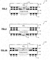
- an integrated circuit (IC) package 100 includes a DDRx package 102 arranged on top of a SOC 104 using package-on-package (POP) technology.
- the SOC 104 is arranged on a package substrate 106.
- the DDRx package 102 is connected to the package substrate 106 using solder balls 108.
- the IC package 100 can be encapsulated and arranged on a printed circuit board (PCB) or attached to another IC using bonding pads 110 and/or solder balls 112.
- the solder balls 108 surround the SOC 104 and limit the width and height of the SOC 104.
- an IC package 150 includes the DDRx package 102 and the SOC 104 arranged in a flip-chip configuration on the package substrate 106. While FIG. 2 shows that the package substrate 106 uses ball grid array (BGA) type packaging, any other type of packaging such as quad flat package (QFP) or quad flat no-leads (QFN) packaging may be used instead.
- BGA ball grid array
- QFP quad flat package
- QFN quad flat no-leads
- an IC package 200 includes a DDRx package 202 and a SOC 204.
- balls 208 used to connect the DDRx package 202 to the package substrate 106 are pushed towards the edges of the DDRx package 202 so that the SOC 204 can be wider than the SOC 104 shown in FIGs. 1 and 2 .
- a standard DDRx package has three rows of .8mm pitch balls on each side of the DDRx package, which leaves little space (shown dotted) for SOC.
- FIG. 3A balls 208 used to connect the DDRx package 202 to the package substrate 106 are pushed towards the edges of the DDRx package 202 so that the SOC 204 can be wider than the SOC 104 shown in FIGs. 1 and 2 .
- a standard DDRx package has three rows of .8mm pitch balls on each side of the DDRx package, which leaves little space (shown dotted) for SOC.
- the three rows of .8mm pitch balls can be reduced to two rows of ⁇ .4mm pitch balls, which leaves more space (shown dotted) than that shown in FIG. 3B .
- the balls 208 can be arranged at ⁇ .4mm pitch.
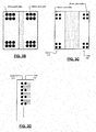
- the balls in the inner row (row adjacent to the SOC) can be arranged farther apart than the balls in the outer row (row adjacent to the edge of the DDRx package). For example, one or more alternate balls in the inner row can be removed to allow extra space for routing connections.
- the inner rows of balls can be arranged slightly sparser. For example, one ball for every two balls can be removed. This will result in about 20 balls for each inner row having 0.4mm pitch. As a result, only 100 pins are necessary for a 12mm high package. This should be sufficient for x32 LP-DDR3 requirement. If insufficient, a few balls can be allocated on the top and bottom edges so long as the balls do not get close to the center of the package since the center of the package is used for opening for the wire bonding of the DRAM die to the substrate.
- an interposer may be used between the DDRx package 102 and the package substrate 106 to create additional space for the SOC 204.
- an IC package 250 includes an interposer 252 arranged between the DDRx package 102 and the package substrate 106.
- the interposer 252 includes the balls 208 that are pushed out toward the edges of the IC package 250. Pushing the balls 208 out toward the edges of the IC package 250 creates additional space for the SOC 204.
- the interposer 252 provides connections between the balls 108 and the balls 208.
- the package substrate 106 can include a window in which the SOC 204 is arranged.
- a package substrate 106-1 includes a window 302.
- the window 302 is arranged along a first surface 304 of the package substrate 106-1 that is opposite to a second surface 306 of the package substrate 106-1, where the first surface 304 is adjacent to the bottom of the IC package 300, and where the second surface 306 is adjacent to the DDRx package 102.
- an IC package 350 includes the interposer 252 and a package substrate 106-2.
- the package substrate 106-2 includes a window 352.
- the window 352 is arranged along a first surface 354 of the package substrate 106-2, where the first surface 354 is adjacent to the interposer 252 and opposite to a second surface 356 of the package substrate 106-2, where the second surface 356 is adjacent to the bottom of the IC package 350.
- an IC package 400 includes two DRAM dies 402-1 and 402-2 and a SOC 404.
- the DRAM dies 402-1 and 402-2 are cut as a pair and are used as a substrate on top of which the SOC 404 is stacked.
- Each of the DRAM dies 402-1 and 402-2 includes three rows of .8mm pitch balls on each side.
- an IC package 450 includes a dual DDRx package 452 stacked on top of a SOC 454.
- the SOC 454 is arranged on a package substrate 456.
- the dual DDRx package 452 includes two DRAM dies 458-1 and 458-2.
- the DRAM dies 458-1 and 458-2 can be separated before packaging.
- the DRAM dies 458-1 and 458-2 can be arranged closer to each other or farther apart from each other.
- Each of the DRAM dies 458-1 and 458-2 includes only three rows of .4mm pitch balls 460-1 and 460-2 on one side instead of three rows of .8mm pitch balls on each side. Since the pitch of the balls 460-1 and 460-2 is half of the pitch of the balls shown in FIG. 5A , the number of balls in the IC package 450 can be doubled in the same amount of space. Accordingly, while the total number of balls per DRAM is the same in FIGs. 5A and 5B , the balls corresponding to a DRAM can be arranged only on one side of the IC package 450.
- connections from the DRAM die 458-1 to the balls 460-1 can be arranged on the left side of the IC package 450, and the connections from the DRAM die 458-2 to the balls 460-2 can be arranged on the right side of the IC package 450.
- the SOC 454 can be arranged on the package substrate 456 in the space between the balls 460-1 of the DRAM 458-1 and the balls 460-2 of the DRAM die 458-2.
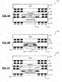
- the IC package 450 is shown in detail.
- the DRAM dies 458-1 and 458-2 are arranged on a package substrate 470.
- the DRAM dies 458-1 and 458-2 may be integrated in a single chip or alternatively implemented as separate chips.
- the package substrate 470 of the dual DDRx package 452 includes two windows 472-1 and 472-2.
- the window openings are not centered but instead slightly offset in such a way that the window openings are placed approximately at a quarter distance of away from the edge of the die (toward inner direction). This can be pictured as if two almost identical DDR3 dies 458-1 and 458-2 are placed next to each other in horizontal direction (assuming existing pins are placed vertically).
- Bonding wires 474-1 and 474-2 respectively connect the DRAM dies 458-1 and 458-2 to the package substrate 470.
- This arrangement in combination with moving the balls 460-1 and 460-2 respectively to the left and right edges of the package substrate 470 (explained above with reference to FIG. 3A ), decreases wiring distances from the DRAM dies 458-1 and 458-2 to the respective balls 460-1 and 460-2. This in turn decreases inductance and parasitic capacitances on high speed signal traces, especially on data pins.
- control and address (C/A) buses can be allocated around the center of the IC package 450 while the data buses can be allocated at the outer corners of the IC package 450. Accordingly, for an x32 (i.e., 32-bit) configuration, 8 data pins can be allocated on each corner, and for an x64 (i.e., 64-bit) configuration, 16 data pins can be allocated on each corner. Further, the extra 8 pins (plus each associated control pin) for supporting the x64 configuration can be arranged at the outer most locations. This results in a smaller DRAM package for the x32 configuration while preserving forward compatibility with the x64 configuration. This allows the x32 configuration to use a smaller package to save cost.
- an IC package 500 including stacked DRAM dies is shown.
- the DRAM dies 458-1 and 458-2 are arranged on a package substrate 470-1
- DRAM dies 458-3 and 458-4 are arranged on a package substrate 470-2.
- the DRAM dies 458-1 and 458-2 arranged on the package substrate 470-1 are stacked vertically on top of the DRAM dies 458-3 and 458-4 arranged on the package substrate 470-2.
- Additional DRAM dies can be stacked vertically on top of the DRAM dies 458-3 and 458-4.
- a heat spreader 508 is arranged on top of the DRAM dies 458-3 and 458-4.
- a heat sink 510 is arranged on top of the heat spreader 508.
- the package substrate 470-1 includes bonding pads 501-1 and 501-2 on lower and upper surfaces of the package substrate 470-1, respectively.
- the balls 460-1 and 460-2 connect the bonding pads 501-1 of the package substrate 470-1 to the package substrate 456.
- Through-silicon vias 502-1 connect the bonding pads 501-1 to the bonding pads 501-2.
- the package substrate 470-2 includes bonding pads 501-3 and 501-4 on lower and upper surfaces of the package substrate 470-2, respectively.
- Through-silicon vias 502-2 connect the bonding pads 501-3 to the bonding pads 501-4.
- Pillars 504 connect the bonding pads 501-2 of the package substrate 470-1 to the bonding pads 501-3 of the package substrate 470-2.
- Other types of connections such as balls may be used instead of the pillars 504.
- DIMM packaging can be eliminated altogether from future PC DRAM requirement. This would be extremely important as the industry moves to DDR4 speed for PC applications.
- Another major benefit of the above approach is that only a single DRAM in the DRAM stack is active during normal operation since each DRAM can supply all 64 signal pins.
- the address and command pins (the C/A pins) are effectively point-to-point as far as the connection to the main CPU (in the SOC 454) is concerned, thus allowing the C/A pins to operate at a much higher clock frequency.
- the C/A pins can also have on-chip termination for at least one of the DRAMs in the stack (e.g., in the top of the stack) to allow very high speed operation. This will reduce power dissipation drastically.
- the entire DRAM needs to be cooled for PC applications (at very high speed)
- only a single stack of DRAM needs to be cooled with a single heat sink 510, thus lowering heat sink cost as well.
- the IC packages disclosed above may be used in a variety of computing devices including, but not limited to, a smartphone, a tablet, a laptop, a personal computer, a television, and a setup box.
Landscapes
- Engineering & Computer Science (AREA)
- Microelectronics & Electronic Packaging (AREA)
- Physics & Mathematics (AREA)
- Computer Hardware Design (AREA)
- Power Engineering (AREA)
- Dram (AREA)
- Condensed Matter Physics & Semiconductors (AREA)
- General Physics & Mathematics (AREA)
- Semiconductor Memories (AREA)
- Geometry (AREA)
Applications Claiming Priority (4)
| Application Number | Priority Date | Filing Date | Title |
|---|---|---|---|
| US201161526586P | 2011-08-23 | 2011-08-23 | |
| US201161548344P | 2011-10-18 | 2011-10-18 | |
| US13/590,949 US8896126B2 (en) | 2011-08-23 | 2012-08-21 | Packaging DRAM and SOC in an IC package |
| EP12753343.8A EP2748850B1 (de) | 2011-08-23 | 2012-08-22 | Verkapselung von dram und soc in einem ic-gehäuse |
Related Parent Applications (2)
| Application Number | Title | Priority Date | Filing Date |
|---|---|---|---|
| EP12753343.8A Division EP2748850B1 (de) | 2011-08-23 | 2012-08-22 | Verkapselung von dram und soc in einem ic-gehäuse |
| EP12753343.8A Division-Into EP2748850B1 (de) | 2011-08-23 | 2012-08-22 | Verkapselung von dram und soc in einem ic-gehäuse |
Publications (2)
| Publication Number | Publication Date |
|---|---|
| EP2884535A2 true EP2884535A2 (de) | 2015-06-17 |
| EP2884535A3 EP2884535A3 (de) | 2015-07-22 |
Family
ID=47742490
Family Applications (2)
| Application Number | Title | Priority Date | Filing Date |
|---|---|---|---|
| EP12753343.8A Active EP2748850B1 (de) | 2011-08-23 | 2012-08-22 | Verkapselung von dram und soc in einem ic-gehäuse |
| EP15150023.8A Ceased EP2884535A3 (de) | 2011-08-23 | 2012-08-22 | Verpackung von DRAM und SOC in einem IC-Gehäuse |
Family Applications Before (1)
| Application Number | Title | Priority Date | Filing Date |
|---|---|---|---|
| EP12753343.8A Active EP2748850B1 (de) | 2011-08-23 | 2012-08-22 | Verkapselung von dram und soc in einem ic-gehäuse |
Country Status (6)
| Country | Link |
|---|---|
| US (2) | US8896126B2 (de) |
| EP (2) | EP2748850B1 (de) |
| JP (1) | JP6117787B2 (de) |
| KR (1) | KR101926102B1 (de) |
| CN (1) | CN103843136B (de) |
| WO (1) | WO2013028745A1 (de) |
Families Citing this family (43)
| Publication number | Priority date | Publication date | Assignee | Title |
|---|---|---|---|---|
| WO2011044289A1 (en) * | 2009-10-07 | 2011-04-14 | Rain Bird Corporation | Volumetric budget based irrigation control |
| US8597986B2 (en) * | 2011-09-01 | 2013-12-03 | Taiwan Semiconductor Manufacturing Co., Ltd. | System in package and method of fabricating same |
| US10163877B2 (en) * | 2011-11-07 | 2018-12-25 | Taiwan Semiconductor Manufacturing Co., Ltd. | System in package process flow |
| KR20130071884A (ko) * | 2011-12-21 | 2013-07-01 | 삼성전자주식회사 | 다이 패키지 및 이를 포함하는 시스템 |
| KR20140067727A (ko) * | 2012-11-27 | 2014-06-05 | 삼성전자주식회사 | 멀티칩 패키지 및 이의 제조 방법 |
| KR102107147B1 (ko) * | 2013-02-01 | 2020-05-26 | 삼성전자주식회사 | 패키지 온 패키지 장치 |
| US9087765B2 (en) * | 2013-03-15 | 2015-07-21 | Qualcomm Incorporated | System-in-package with interposer pitch adapter |
| KR20140130921A (ko) * | 2013-05-02 | 2014-11-12 | 삼성전자주식회사 | 반도체 패키지 및 그 제조 방법 |
| KR102127772B1 (ko) * | 2013-05-16 | 2020-06-29 | 삼성전자주식회사 | 방열 판을 갖는 반도체 패키지 및 그 형성 방법 |
| JPWO2014188632A1 (ja) * | 2013-05-23 | 2017-02-23 | パナソニック株式会社 | 放熱構造を有する半導体装置および半導体装置の積層体 |
| KR102144367B1 (ko) * | 2013-10-22 | 2020-08-14 | 삼성전자주식회사 | 반도체 패키지 및 이의 제조 방법 |
| US9379078B2 (en) * | 2013-11-07 | 2016-06-28 | Taiwan Semiconductor Manufacturing Company, Ltd. | 3D die stacking structure with fine pitches |
| JP2015216263A (ja) * | 2014-05-12 | 2015-12-03 | マイクロン テクノロジー, インク. | 半導体装置 |
| TWI690029B (zh) * | 2014-06-13 | 2020-04-01 | 蘋果公司 | 重組態之寬輸入輸出記憶體模組及使用其之封裝架構 |
| US20160013156A1 (en) * | 2014-07-14 | 2016-01-14 | Apple Inc. | Package-on-package options with multiple layer 3-d stacking |
| US9576900B2 (en) * | 2015-02-11 | 2017-02-21 | Endura Technologies LLC | Switched power stage with integrated passive components |
| US10360972B2 (en) * | 2015-03-10 | 2019-07-23 | Rambus Inc. | Memories and memory components with interconnected and redundant data interfaces |
| JP6305961B2 (ja) * | 2015-08-04 | 2018-04-04 | オートモーティブエナジーサプライ株式会社 | リチウムイオン二次電池 |
| KR102413441B1 (ko) | 2015-11-12 | 2022-06-28 | 삼성전자주식회사 | 반도체 패키지 |
| CN108353505B (zh) * | 2015-11-13 | 2021-11-30 | 英特尔公司 | 包括衬底桥的电子组件 |
| WO2017105421A1 (en) | 2015-12-16 | 2017-06-22 | Intel Corporation | Dynamic random access memory (dram) mounts |
| KR102556052B1 (ko) * | 2015-12-23 | 2023-07-14 | 삼성전자주식회사 | 시스템 모듈과 이를 포함하는 모바일 컴퓨팅 장치 |
| KR102533236B1 (ko) | 2016-06-20 | 2023-05-17 | 삼성전자주식회사 | 개선된 레이턴시를 갖는 메모리 장치 및 그것의 동작 방법 |
| KR102547800B1 (ko) * | 2016-08-23 | 2023-06-26 | 삼성전자주식회사 | 그래핀 퀀텀닷을 이용한 방열 구조체 및 그 제조방법 |
| JP6733534B2 (ja) * | 2016-12-16 | 2020-08-05 | 住友電気工業株式会社 | 半導体装置およびその製造方法 |
| KR20180130043A (ko) * | 2017-05-25 | 2018-12-06 | 에스케이하이닉스 주식회사 | 칩 스택들을 가지는 반도체 패키지 |
| US10153221B1 (en) * | 2017-06-13 | 2018-12-11 | Micron Technology, Inc. | Face down dual sided chip scale memory package |
| KR102109570B1 (ko) * | 2018-07-24 | 2020-05-12 | 삼성전자주식회사 | 반도체 패키지 실장 기판 |
| CN109472099A (zh) * | 2018-11-19 | 2019-03-15 | 郑州云海信息技术有限公司 | 一种服务器的印刷电路板及制作方法 |
| US20190115293A1 (en) * | 2018-12-12 | 2019-04-18 | Intel Corporation | Multiple ball grid array (bga) configurations for a single integrated circuit (ic) package |
| US11139270B2 (en) | 2019-03-18 | 2021-10-05 | Kepler Computing Inc. | Artificial intelligence processor with three-dimensional stacked memory |
| US11836102B1 (en) | 2019-03-20 | 2023-12-05 | Kepler Computing Inc. | Low latency and high bandwidth artificial intelligence processor |
| KR102679095B1 (ko) * | 2019-05-30 | 2024-07-01 | 삼성전자주식회사 | 반도체 패키지 |
| US11844223B1 (en) | 2019-05-31 | 2023-12-12 | Kepler Computing Inc. | Ferroelectric memory chiplet as unified memory in a multi-dimensional packaging |
| US11152343B1 (en) | 2019-05-31 | 2021-10-19 | Kepler Computing, Inc. | 3D integrated ultra high-bandwidth multi-stacked memory |
| US12086410B1 (en) | 2019-05-31 | 2024-09-10 | Kepler Computing Inc. | Ferroelectric memory chiplet in a multi-dimensional packaging with I/O switch embedded in a substrate or interposer |
| KR102600154B1 (ko) * | 2019-06-12 | 2023-11-07 | 삼성전자주식회사 | 반도체 패키지 |
| US11348856B2 (en) * | 2019-12-20 | 2022-05-31 | Micron Technology, Inc. | Thermal cooling element for memory devices of a memory sub-system |
| CN112382624B (zh) * | 2020-11-30 | 2026-01-27 | 海光信息技术股份有限公司 | 一种芯片及主板 |
| US11791233B1 (en) | 2021-08-06 | 2023-10-17 | Kepler Computing Inc. | Ferroelectric or paraelectric memory and logic chiplet with thermal management in a multi-dimensional packaging |
| JP2023096595A (ja) * | 2021-12-27 | 2023-07-07 | キオクシア株式会社 | 半導体装置 |
| KR102462798B1 (ko) | 2022-02-07 | 2022-11-03 | 최해용 | 공간 보면대 장치 |
| US12341123B2 (en) * | 2022-05-12 | 2025-06-24 | Nanya Technology Corporation | Semiconductor device having a bonding wire in a hole in the substrate |
Citations (4)
| Publication number | Priority date | Publication date | Assignee | Title |
|---|---|---|---|---|
| KR20060120365A (ko) * | 2005-05-19 | 2006-11-27 | 삼성테크윈 주식회사 | 반도체 칩 적층 패키지 |
| US20070040261A1 (en) * | 2004-02-23 | 2007-02-22 | Wolfgang Hetzel | Semiconductor component comprising an interposer substrate and method for the production thereof |
| US20070241441A1 (en) * | 2006-04-17 | 2007-10-18 | Stats Chippac Ltd. | Multichip package system |
| US20120155049A1 (en) * | 2010-12-17 | 2012-06-21 | Tessera Research Llc | Enhanced stacked microelectronic assemblies with central contacts |
Family Cites Families (27)
| Publication number | Priority date | Publication date | Assignee | Title |
|---|---|---|---|---|
| US6049129A (en) | 1997-12-19 | 2000-04-11 | Texas Instruments Incorporated | Chip size integrated circuit package |
| US5854507A (en) | 1998-07-21 | 1998-12-29 | Hewlett-Packard Company | Multiple chip assembly |
| US6815251B1 (en) | 1999-02-01 | 2004-11-09 | Micron Technology, Inc. | High density modularity for IC's |
| US6825550B2 (en) | 1999-09-02 | 2004-11-30 | Micron Technology, Inc. | Board-on-chip packages with conductive foil on the chip surface |
| KR20010064907A (ko) | 1999-12-20 | 2001-07-11 | 마이클 디. 오브라이언 | 와이어본딩 방법 및 이를 이용한 반도체패키지 |
| US6414396B1 (en) * | 2000-01-24 | 2002-07-02 | Amkor Technology, Inc. | Package for stacked integrated circuits |
| JP2001223324A (ja) | 2000-02-10 | 2001-08-17 | Mitsubishi Electric Corp | 半導体装置 |
| US6731011B2 (en) | 2002-02-19 | 2004-05-04 | Matrix Semiconductor, Inc. | Memory module having interconnected and stacked integrated circuits |
| JP3867796B2 (ja) * | 2003-10-09 | 2007-01-10 | セイコーエプソン株式会社 | 半導体装置及びその製造方法、回路基板並びに電子機器 |
| US7061121B2 (en) | 2003-11-12 | 2006-06-13 | Tessera, Inc. | Stacked microelectronic assemblies with central contacts |
| US7851899B2 (en) | 2004-04-02 | 2010-12-14 | Utac - United Test And Assembly Test Center Ltd. | Multi-chip ball grid array package and method of manufacture |
| TW200614448A (en) * | 2004-10-28 | 2006-05-01 | Advanced Semiconductor Eng | Method for stacking bga packages and structure from the same |
| SG122016A1 (en) | 2004-10-28 | 2006-05-26 | United Test & Assembly Ct Ltd | Semiconductor chip package and method of manufacture |
| US7368319B2 (en) | 2006-03-17 | 2008-05-06 | Stats Chippac Ltd. | Stacked integrated circuit package-in-package system |
| SG136822A1 (en) | 2006-04-19 | 2007-11-29 | Micron Technology Inc | Integrated circuit devices with stacked package interposers |
| US7535110B2 (en) | 2006-06-15 | 2009-05-19 | Marvell World Trade Ltd. | Stack die packages |
| US7518226B2 (en) | 2007-02-06 | 2009-04-14 | Stats Chippac Ltd. | Integrated circuit packaging system with interposer |
| US7816154B2 (en) * | 2007-06-06 | 2010-10-19 | Renesas Electronics Corporation | Semiconductor device, a method of manufacturing a semiconductor device and a testing method of the same |
| JP4829853B2 (ja) * | 2007-08-24 | 2011-12-07 | 力成科技股▲分▼有限公司 | 半導体pop装置 |
| KR101329355B1 (ko) * | 2007-08-31 | 2013-11-20 | 삼성전자주식회사 | 적층형 반도체 패키지, 그 형성방법 및 이를 구비하는전자장치 |
| KR20090043898A (ko) | 2007-10-30 | 2009-05-07 | 삼성전자주식회사 | 스택 패키지 및 그 제조 방법, 및 스택 패키지를 포함하는카드 및 시스템 |
| KR20090050810A (ko) * | 2007-11-16 | 2009-05-20 | 삼성전자주식회사 | 접합 신뢰성이 향상된 적층형 반도체 패키지 |
| US8247894B2 (en) * | 2008-03-24 | 2012-08-21 | Stats Chippac Ltd. | Integrated circuit package system with step mold recess |
| US8354742B2 (en) * | 2008-03-31 | 2013-01-15 | Stats Chippac, Ltd. | Method and apparatus for a package having multiple stacked die |
| US8253231B2 (en) | 2008-09-23 | 2012-08-28 | Marvell International Ltd. | Stacked integrated circuit package using a window substrate |
| KR101601847B1 (ko) * | 2009-05-21 | 2016-03-09 | 삼성전자주식회사 | 반도체 패키지 |
| KR20120007839A (ko) * | 2010-07-15 | 2012-01-25 | 삼성전자주식회사 | 적층형 반도체 패키지의 제조방법 |
-
2012
- 2012-08-21 US US13/590,949 patent/US8896126B2/en not_active Expired - Fee Related
- 2012-08-22 WO PCT/US2012/051841 patent/WO2013028745A1/en not_active Ceased
- 2012-08-22 EP EP12753343.8A patent/EP2748850B1/de active Active
- 2012-08-22 CN CN201280048525.1A patent/CN103843136B/zh active Active
- 2012-08-22 KR KR1020147007564A patent/KR101926102B1/ko active Active
- 2012-08-22 EP EP15150023.8A patent/EP2884535A3/de not_active Ceased
- 2012-08-22 JP JP2014527256A patent/JP6117787B2/ja active Active
-
2014
- 2014-11-25 US US14/553,185 patent/US9236350B2/en active Active
Patent Citations (4)
| Publication number | Priority date | Publication date | Assignee | Title |
|---|---|---|---|---|
| US20070040261A1 (en) * | 2004-02-23 | 2007-02-22 | Wolfgang Hetzel | Semiconductor component comprising an interposer substrate and method for the production thereof |
| KR20060120365A (ko) * | 2005-05-19 | 2006-11-27 | 삼성테크윈 주식회사 | 반도체 칩 적층 패키지 |
| US20070241441A1 (en) * | 2006-04-17 | 2007-10-18 | Stats Chippac Ltd. | Multichip package system |
| US20120155049A1 (en) * | 2010-12-17 | 2012-06-21 | Tessera Research Llc | Enhanced stacked microelectronic assemblies with central contacts |
Also Published As
| Publication number | Publication date |
|---|---|
| US20150076687A1 (en) | 2015-03-19 |
| US9236350B2 (en) | 2016-01-12 |
| JP6117787B2 (ja) | 2017-04-19 |
| US8896126B2 (en) | 2014-11-25 |
| CN103843136B (zh) | 2018-11-09 |
| WO2013028745A1 (en) | 2013-02-28 |
| EP2884535A3 (de) | 2015-07-22 |
| JP2014529898A (ja) | 2014-11-13 |
| EP2748850A1 (de) | 2014-07-02 |
| KR101926102B1 (ko) | 2018-12-06 |
| KR20140060317A (ko) | 2014-05-19 |
| CN103843136A (zh) | 2014-06-04 |
| US20130049224A1 (en) | 2013-02-28 |
| EP2748850B1 (de) | 2018-08-22 |
Similar Documents
| Publication | Publication Date | Title |
|---|---|---|
| US8896126B2 (en) | Packaging DRAM and SOC in an IC package | |
| US8796863B2 (en) | Semiconductor memory devices and semiconductor packages | |
| CN109599134B (zh) | 具有控制器及存储器堆叠的灵活存储器系统 | |
| CN104704631A (zh) | 堆叠式多芯片集成电路封装 | |
| US9123554B2 (en) | Semiconductor device | |
| US10777530B2 (en) | Package-on-package semiconductor device assemblies including one or more windows and related methods and packages | |
| JP4707446B2 (ja) | 半導体装置 | |
| US9865310B2 (en) | High density memory modules | |
| US10734393B2 (en) | Methods of forming package structures for enhanced memory capacity and structures formed thereby | |
| WO2016165607A1 (zh) | 一种集成电路、引线键合封装芯片及倒装封装芯片 | |
| US20150108656A1 (en) | Stacked die package | |
| US20200027867A1 (en) | Dynamic random access memory (dram) mounts | |
| US9472539B2 (en) | Semiconductor chip and a semiconductor package having a package on package (POP) structure including the semiconductor chip | |
| US20250029957A1 (en) | Semiconductor devices including stacked dies with interleaved wire bonds and associated systems and methods | |
| US9226398B1 (en) | Printed circuit board and package substrate having additional conductive pathway space | |
| US20240395355A1 (en) | Memory device | |
| CN202259245U (zh) | 一种芯片的封装结构 | |
| WO2023084737A1 (ja) | モジュール及びその製造方法 | |
| Solberg et al. | High density SDRAM package solution for next generation product board applications |
Legal Events
| Date | Code | Title | Description |
|---|---|---|---|
| PUAI | Public reference made under article 153(3) epc to a published international application that has entered the european phase |
Free format text: ORIGINAL CODE: 0009012 |
|
| 17P | Request for examination filed |
Effective date: 20150102 |
|
| AC | Divisional application: reference to earlier application |
Ref document number: 2748850 Country of ref document: EP Kind code of ref document: P |
|
| AK | Designated contracting states |
Kind code of ref document: A2 Designated state(s): AL AT BE BG CH CY CZ DE DK EE ES FI FR GB GR HR HU IE IS IT LI LT LU LV MC MK MT NL NO PL PT RO RS SE SI SK SM TR |
|
| PUAL | Search report despatched |
Free format text: ORIGINAL CODE: 0009013 |
|
| AK | Designated contracting states |
Kind code of ref document: A3 Designated state(s): AL AT BE BG CH CY CZ DE DK EE ES FI FR GB GR HR HU IE IS IT LI LT LU LV MC MK MT NL NO PL PT RO RS SE SI SK SM TR |
|
| RIC1 | Information provided on ipc code assigned before grant |
Ipc: H01L 25/18 20060101AFI20150617BHEP Ipc: H01L 25/065 20060101ALN20150617BHEP Ipc: H01L 25/10 20060101ALN20150617BHEP Ipc: H01L 23/498 20060101ALI20150617BHEP Ipc: H01L 23/13 20060101ALN20150617BHEP Ipc: H01L 21/60 20060101ALI20150617BHEP |
|
| STAA | Information on the status of an ep patent application or granted ep patent |
Free format text: STATUS: EXAMINATION IS IN PROGRESS |
|
| 17Q | First examination report despatched |
Effective date: 20180823 |
|
| RAP1 | Party data changed (applicant data changed or rights of an application transferred) |
Owner name: MARVELL ASIA PTE, LTD. |
|
| STAA | Information on the status of an ep patent application or granted ep patent |
Free format text: STATUS: THE APPLICATION HAS BEEN REFUSED |
|
| 18R | Application refused |
Effective date: 20211114 |