EP2808947A1 - Crimpklemme, crimpverbindungsstruktur und verfahren zur herstellung einer crimpverbindungsstruktur - Google Patents
Crimpklemme, crimpverbindungsstruktur und verfahren zur herstellung einer crimpverbindungsstruktur Download PDFInfo
- Publication number
- EP2808947A1 EP2808947A1 EP13875327.2A EP13875327A EP2808947A1 EP 2808947 A1 EP2808947 A1 EP 2808947A1 EP 13875327 A EP13875327 A EP 13875327A EP 2808947 A1 EP2808947 A1 EP 2808947A1
- Authority
- EP
- European Patent Office
- Prior art keywords
- crimping
- wire
- crimp terminal
- crimp
- insulated wire
- Prior art date
- Legal status (The legal status is an assumption and is not a legal conclusion. Google has not performed a legal analysis and makes no representation as to the accuracy of the status listed.)
- Withdrawn
Links
Images


Classifications
-
- H—ELECTRICITY
- H01—ELECTRIC ELEMENTS
- H01R—ELECTRICALLY-CONDUCTIVE CONNECTIONS; STRUCTURAL ASSOCIATIONS OF A PLURALITY OF MUTUALLY-INSULATED ELECTRICAL CONNECTING ELEMENTS; COUPLING DEVICES; CURRENT COLLECTORS
- H01R4/00—Electrically-conductive connections between two or more conductive members in direct contact, i.e. touching one another; Means for effecting or maintaining such contact; Electrically-conductive connections having two or more spaced connecting locations for conductors and using contact members penetrating insulation
- H01R4/10—Electrically-conductive connections between two or more conductive members in direct contact, i.e. touching one another; Means for effecting or maintaining such contact; Electrically-conductive connections having two or more spaced connecting locations for conductors and using contact members penetrating insulation effected solely by twisting, wrapping, bending, crimping, or other permanent deformation
- H01R4/18—Electrically-conductive connections between two or more conductive members in direct contact, i.e. touching one another; Means for effecting or maintaining such contact; Electrically-conductive connections having two or more spaced connecting locations for conductors and using contact members penetrating insulation effected solely by twisting, wrapping, bending, crimping, or other permanent deformation by crimping
- H01R4/183—Electrically-conductive connections between two or more conductive members in direct contact, i.e. touching one another; Means for effecting or maintaining such contact; Electrically-conductive connections having two or more spaced connecting locations for conductors and using contact members penetrating insulation effected solely by twisting, wrapping, bending, crimping, or other permanent deformation by crimping for cylindrical elongated bodies, e.g. cables having circular cross-section
-
- H—ELECTRICITY
- H01—ELECTRIC ELEMENTS
- H01R—ELECTRICALLY-CONDUCTIVE CONNECTIONS; STRUCTURAL ASSOCIATIONS OF A PLURALITY OF MUTUALLY-INSULATED ELECTRICAL CONNECTING ELEMENTS; COUPLING DEVICES; CURRENT COLLECTORS
- H01R4/00—Electrically-conductive connections between two or more conductive members in direct contact, i.e. touching one another; Means for effecting or maintaining such contact; Electrically-conductive connections having two or more spaced connecting locations for conductors and using contact members penetrating insulation
- H01R4/10—Electrically-conductive connections between two or more conductive members in direct contact, i.e. touching one another; Means for effecting or maintaining such contact; Electrically-conductive connections having two or more spaced connecting locations for conductors and using contact members penetrating insulation effected solely by twisting, wrapping, bending, crimping, or other permanent deformation
- H01R4/18—Electrically-conductive connections between two or more conductive members in direct contact, i.e. touching one another; Means for effecting or maintaining such contact; Electrically-conductive connections having two or more spaced connecting locations for conductors and using contact members penetrating insulation effected solely by twisting, wrapping, bending, crimping, or other permanent deformation by crimping
- H01R4/187—Electrically-conductive connections between two or more conductive members in direct contact, i.e. touching one another; Means for effecting or maintaining such contact; Electrically-conductive connections having two or more spaced connecting locations for conductors and using contact members penetrating insulation effected solely by twisting, wrapping, bending, crimping, or other permanent deformation by crimping combined with soldering or welding
-
- H—ELECTRICITY
- H01—ELECTRIC ELEMENTS
- H01R—ELECTRICALLY-CONDUCTIVE CONNECTIONS; STRUCTURAL ASSOCIATIONS OF A PLURALITY OF MUTUALLY-INSULATED ELECTRICAL CONNECTING ELEMENTS; COUPLING DEVICES; CURRENT COLLECTORS
- H01R4/00—Electrically-conductive connections between two or more conductive members in direct contact, i.e. touching one another; Means for effecting or maintaining such contact; Electrically-conductive connections having two or more spaced connecting locations for conductors and using contact members penetrating insulation
- H01R4/10—Electrically-conductive connections between two or more conductive members in direct contact, i.e. touching one another; Means for effecting or maintaining such contact; Electrically-conductive connections having two or more spaced connecting locations for conductors and using contact members penetrating insulation effected solely by twisting, wrapping, bending, crimping, or other permanent deformation
- H01R4/18—Electrically-conductive connections between two or more conductive members in direct contact, i.e. touching one another; Means for effecting or maintaining such contact; Electrically-conductive connections having two or more spaced connecting locations for conductors and using contact members penetrating insulation effected solely by twisting, wrapping, bending, crimping, or other permanent deformation by crimping
- H01R4/20—Electrically-conductive connections between two or more conductive members in direct contact, i.e. touching one another; Means for effecting or maintaining such contact; Electrically-conductive connections having two or more spaced connecting locations for conductors and using contact members penetrating insulation effected solely by twisting, wrapping, bending, crimping, or other permanent deformation by crimping using a crimping sleeve
- H01R4/203—Electrically-conductive connections between two or more conductive members in direct contact, i.e. touching one another; Means for effecting or maintaining such contact; Electrically-conductive connections having two or more spaced connecting locations for conductors and using contact members penetrating insulation effected solely by twisting, wrapping, bending, crimping, or other permanent deformation by crimping using a crimping sleeve having an uneven wire-receiving surface to improve the contact
- H01R4/206—Electrically-conductive connections between two or more conductive members in direct contact, i.e. touching one another; Means for effecting or maintaining such contact; Electrically-conductive connections having two or more spaced connecting locations for conductors and using contact members penetrating insulation effected solely by twisting, wrapping, bending, crimping, or other permanent deformation by crimping using a crimping sleeve having an uneven wire-receiving surface to improve the contact with transversal grooves or threads
-
- H—ELECTRICITY
- H01—ELECTRIC ELEMENTS
- H01R—ELECTRICALLY-CONDUCTIVE CONNECTIONS; STRUCTURAL ASSOCIATIONS OF A PLURALITY OF MUTUALLY-INSULATED ELECTRICAL CONNECTING ELEMENTS; COUPLING DEVICES; CURRENT COLLECTORS
- H01R4/00—Electrically-conductive connections between two or more conductive members in direct contact, i.e. touching one another; Means for effecting or maintaining such contact; Electrically-conductive connections having two or more spaced connecting locations for conductors and using contact members penetrating insulation
- H01R4/58—Electrically-conductive connections between two or more conductive members in direct contact, i.e. touching one another; Means for effecting or maintaining such contact; Electrically-conductive connections having two or more spaced connecting locations for conductors and using contact members penetrating insulation characterised by the form or material of the contacting members
- H01R4/62—Connections between conductors of different materials; Connections between or with aluminium or steel-core aluminium conductors
-
- H—ELECTRICITY
- H01—ELECTRIC ELEMENTS
- H01R—ELECTRICALLY-CONDUCTIVE CONNECTIONS; STRUCTURAL ASSOCIATIONS OF A PLURALITY OF MUTUALLY-INSULATED ELECTRICAL CONNECTING ELEMENTS; COUPLING DEVICES; CURRENT COLLECTORS
- H01R43/00—Apparatus or processes specially adapted for manufacturing, assembling, maintaining, or repairing of line connectors or current collectors or for joining electric conductors
- H01R43/04—Apparatus or processes specially adapted for manufacturing, assembling, maintaining, or repairing of line connectors or current collectors or for joining electric conductors for forming connections by deformation, e.g. crimping tool
- H01R43/048—Crimping apparatus or processes
-
- Y—GENERAL TAGGING OF NEW TECHNOLOGICAL DEVELOPMENTS; GENERAL TAGGING OF CROSS-SECTIONAL TECHNOLOGIES SPANNING OVER SEVERAL SECTIONS OF THE IPC; TECHNICAL SUBJECTS COVERED BY FORMER USPC CROSS-REFERENCE ART COLLECTIONS [XRACs] AND DIGESTS
- Y10—TECHNICAL SUBJECTS COVERED BY FORMER USPC
- Y10T—TECHNICAL SUBJECTS COVERED BY FORMER US CLASSIFICATION
- Y10T29/00—Metal working
- Y10T29/49—Method of mechanical manufacture
- Y10T29/49002—Electrical device making
- Y10T29/49117—Conductor or circuit manufacturing
- Y10T29/49174—Assembling terminal to elongated conductor
- Y10T29/49181—Assembling terminal to elongated conductor by deforming
- Y10T29/49185—Assembling terminal to elongated conductor by deforming of terminal
Definitions
- the present invention relates to a crimp terminal to which an insulated wire is crimp-connected, a crimp-connection structural body in which an insulated wire is crimp-connected to a crimp terminal, and a method for manufacturing a crimp-connection structural body.
- Electric circuits of the automobiles equipped with the various electric and electronic parts are formed by arranging wire harnesses bundling a plurality of insulated wires and by connecting the wire harnesses with one another by connectors.
- the insulated wires are configured to be connected with one another by providing a crimp terminal crimping the insulated wires with crimping portion and fit-connecting a male crimp terminal to a female crimp terminal.
- a gap is produced between a conductor, made of an aluminum core wire or the like, exposed from an end portion of the insulating cover of the insulated wire and the crimping portion, and thus the exposed conductor is exposed to an open air.
- a moisture which if permeates the crimping portion in this state, causes a surface of the exposed conductor to be corroded, thereby increasing an electric resistance, and thus decreasing the conductivity of the conductor. If the conductivity of the conductor decreases to a great degree, it is not possible to supply an electric power to the electric and electronic parts stably.
- Patent Literature 1 discloses a technology of restraining the moisture from contacting the exposed conductor by covering the exposed conductor with a highly viscous resin-made insulator.
- Patent Literature 1 Japanese Laid-open Patent Publication No. 2011-233328
- Patent Literature 1 needs an additional step of covering the exposed portion of the conductor with an insulator after the insulated wire is crimp-connected.
- the technology described by Patent Literature 1 requires a lot of time and effort for crimp-connecting of the insulated wire, thereby an efficiency of a step of crimping the insulated wire decreases.
- a technology has been expected to be developed that is capable of restraining a so-called deterioration of a conductor, i.e. lowering of mechanical strength or lowering of the conductivity of the conductor caused by the corrosion of the conductor caused by the permeation of moisture, by improving sealability to a greater degree without lowering the efficiency of a step of crimping the insulated wire.
- the present invention has been made in view of the above and an object of the present invention is to provide a crimp terminal, a crimp-connection structural body, and a method for producing the crimp-connection structural body, that are capable of restraining deterioration of a conductor from being caused by permeation of moisture without lowering the efficiency of a step of crimping of the insulated wire.
- a crimp terminal includes a crimping portion crimp-connecting a conductor portion exposed from an insulated wire including the conductor portion and a cover covering the conductor portion, in which, the crimping portion is formed in a hollow cylindrical shape in cross section and has first end portion and a second end portion opposite to the first end portion, the conductor portion is inserted into the first end portion in a longitudinal direction, and the second end portion is sealed, the second end portion at the opposite side is sealed by welding, the crimping portion, in which the exposed conductor portion is crimped, further includes a locking section locking the exposed conductor portion, and a length between the first end portion into which the conductor portion is inserted and a portion, of the locking section, that is the closest to the first end portion is larger than a length of the exposed conductor portion of the insulated wire.
- the crimping portion, into which the exposed conductor portion is inserted has a guide section, and an inner diameter of the guide section is smaller than an outer diameter of the cover of the insulated wire and larger than an outer diameter of the conductor portion in the above-described invention.
- a difference between the inner diameter formed by the guide section of the crimping portion and the outer diameter of the exposed conductor portion is larger than a difference between an inner diameter of the first end portion of the crimping portion into which the exposed conductor portion is inserted and the outer diameter of the cover of the insulated wire in the above-described invention.
- an outer diameter of the exposed conductor portion is smaller than the outer diameter of the cover of the insulated wire, and an inner diameter of the first end portion of the crimping portion into which the exposed conductor portion is inserted is larger than the outer diameter of the cover of the insulated wire in the above-described invention.
- the sealed second end portion is sealed by fiber laser welding in the above-described invention.
- the conductor portion is made of an aluminum-based material
- the crimping portion is made of a copper-based material in the above-described invention.
- a crimp-connection structural body includes the crimp terminal of the above-described invention and the insulated wire in which the conductor portion is crimp-connected to the crimp terminal.
- the crimp-connection structural body configures a wire harness including at least a combination of the crimp terminal and the insulated wire in the above-described invention.
- a method for manufacturing a crimp-connection structural body includes: inserting the insulated wire into the crimp terminal of the above-described invention; and crimp-connecting the exposed conductor portion of the insulated wire to the crimp terminal.
- the present invention is capable of restraining deterioration of a conductor from being caused by permeation of moisture without lowering the efficiency of a step of crimping of the insulated wire by improving a sealability of moisture to a greater degree.
- a configuration of a crimp terminal as a first embodiment of the present invention will be explained with reference to FIG. 1 .
- FIG. 1 is a perspective view of a cross section, cut and viewed in the middle of a width direction, of a crimp terminal according to a first embodiment of the present invention.
- the crimp terminal 10 according to the first embodiment of the present invention includes a box section 20 and a crimping portion 30.
- the box section 20 has a shape of hollow quadrangular prism and is formed as a female crimp terminal.
- An insertion tab included in a male crimp terminal is inserted into the box section 20 from a front end toward a rear end in the longitudinal direction X.
- the crimping portion 30 has an approximate O-shape in rear view and is provided at the back of the box section 20 via a predetermined length of transition section 40.
- the longitudinal direction X indicates a direction which coincides with a longitudinal direction of an insulated wire crimp-connected by the crimping portion 30, and a width direction Y indicates a direction which is orthogonal to the longitudinal direction X in an approximately horizontal plane.
- a height direction Z indicates a direction which is approximately orthogonal to an X-Y plane defined by the longitudinal direction X and the width direction Y.
- a term "forward” indicates an arrow directed from the crimping portion 30 to the box section 20
- a term “backward” indicates an arrow directed from the box section 20 to the crimping portion 30.
- the crimp terminal 10 may be a male crimp terminal including an insertion tab, inserted into and connected to the box section 20, and a crimping portion 30 as long as the crimp terminal 10 is a crimp terminal having the crimping portion 30.
- the crimp terminal 10 may be a crimp terminal not having a box section nor an insertion tab but having only a plurality of crimping portions 30 for conductors of a plurality of insulated wires to be inserted into, crimped with, and connected integrally respectively.
- the crimp terminal 10 is a closed-barrel type of terminal manufactured by punching a copper alloy strip, e.g. a plate of brass or the like of which surface is subjected to a tin-plating (Sn-plating) into a shape of the crimp terminal 10 deployed in plane, bending the copper alloy strip into a 3-dimensional shape of terminal having the box section 20 having a hollow quadrangular prism shape and the crimping portion 30 having an approximate O-shape in rear view, and then welding the crimping portion 30.
- a copper alloy strip e.g. a plate of brass or the like of which surface is subjected to a tin-plating (Sn-plating) into a shape of the crimp terminal 10 deployed in plane
- bending the copper alloy strip into a 3-dimensional shape of terminal having the box section 20 having a hollow quadrangular prism shape and the crimping portion 30 having an approximate O-shape in rear view, and then welding the crimping
- the box section 20 is provided with an elastic contact piece 21 being bent toward backward in the longitudinal direction X and contacting the insertion tab of the male crimp terminal.
- the box section 20 is configured to be of an approximate rectangular shape viewed in front in the longitudinal direction X by bending side parts 23, formed consecutively at both sides of the bottom surface portion 22 in the width direction Y, to overlap each other.
- the crimping portion 30 prior to crimping of the insulated wires thereto is approximately O-shaped in rear view by rolling barrel-forming pieces 32, extending at both side of the crimping surface 31 in the width direction Y, so that crimping surfaces 31 come inside and butt welding facing end sections 32a of the barrel-forming piece 32 with each other.
- the length of the barrel-forming piece 32 in the longitudinal direction X is longer than a length of a conductor portion exposed from the insulated wire in the longitudinal direction X.
- the crimping portion 30 is of a hollow cylindrical shape including a cover crimping range 30a crimping an insulating cover as a cover for the insulated wire, an electric wire crimping range 30b crimping an electric wire exposed from the insulated wire, and a sealing portion 30c of which front end portion relative to the electric wire crimping range 30b is crushed to be deformed in a substantial planar shape at an opposite side to the cover crimping range 30a.
- protrusive guide sections 33 Formed on an inner surface of the crimping portion 30 are protrusive guide sections 33 on an entire inner circumference of the crimping portion 30 and a plurality of electric-wire-locking grooves 34 extending in a Y-Z plane and being disposed along the longitudinal direction X with a predetermined interval.
- the guide section 33 is formed to be an annular protrusion at a border of the cover crimping range 30a and the electric wire crimping range 30b in the crimping portion 30.
- the guide section 33 according to the present embodiment is formed in an annular shape on the entire inner circumference of the crimping portion 30, the guide section 33 may not have to be formed on the entire circumference.
- guide sections may be formed separately in two or more areas along the inner circumference.
- the center of a circle, or an apex of a central angle of a circular arc, determined by an inner diameter of the guide section 33 crosses a central axis of a cylinder formed by the crimping portion 30 in parallel with the X direction substantially.
- the electric-wire-locking groove 34 is formed in a rectangular recessed shape viewed in cross section.
- the electric-wire-locking groove 34 formed from the crimping surface 31 to halfway to the barrel-forming piece 32 improves conductivity between the crimping portion 30 and the electric wire because the electric wire exposed from the insulated wire cuts into the electric-wire-locking groove 34.
- the electric-wire-locking groove may be formed continuously within a range between the crimping surface 31 and the barrel-forming piece 32, i.e. an annular groove in the crimping portion 30.
- the electric-wire-locking groove 34 is formed as a groove, a state of the locking portion is not limited to a groove, and for example, round holes or rectangular holes (recess portions) may be disposed separately.
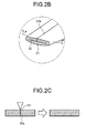
- FIG. 2A is a schematic isometric view of a bottom surface side of the crimp terminal 10 seeing through the box section 20 of the crimp terminal 10.
- FIG. 2B is an enlarged view of an area R shown in FIG. 2A .
- FIG. 2C is an X-X cross sectional view of a portion around facing end sections 32a shown in FIG. 2B .
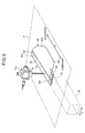
- FIG. 3 illustrates a method for welding the crimping portion 30.
- the crimp terminal 10 is manufactured by punching a copper alloy strip into a shape of a terminal deployed in plane, bending the punched copper alloy strip into a 3-dimensional shape of the terminal having the box section 20 having a hollow quadrangular prism shape and the crimping portion 30 having an approximate O-shape in rear view, and then welding the crimping portion 30.
- the crimping portion 30 is formed by welding a longitudinal direction welding point W1, by butting facing end sections 32a of the barrel-forming piece 32 in the longitudinal direction X, and a width-directional welding point W2, being made in the width direction Y and sealing a front end of the sealing portion 30c of the crimping portion 30 completely.
- the production of the crimping portion 30 begins with butting the facing end sections 32a at a bottom surface side so that the crimping surface 31 and the barrel-forming piece 32 are rolled to constitute a cylindrical shape.
- FIG. 2B an upper side of a cylindrical front portion is pushed to a bottom side of the cylindrical front portion to be deformed in a substantial planar shape.
- FIG. 2C the longitudinal direction welding point W1, in which the cylindrical facing end sections 32a are butted with each other, is welded, and after that the width-directional welding point W2 is welded.
- the longitudinal direction welding point W1 and the width-directional welding point W2 are disposed to be on a plane that is the same as a virtual plane P shown in FIG. 3 , the longitudinal direction welding point W1 and the width-directional welding point W2 can be welded by a monofocal laser welding.
- the longitudinal direction welding point W1 and the width-directional welding point W2 are welded by fiber laser welding using a fiber laser welding device Fw.
- the fiber laser welding indicates a welding using fiber laser light at an approximately 1.08 ⁇ m of wavelength. Since the fiber laser light is an ideal Gaussian beam and can be condensed to a diffraction limit, equal to or smaller than 30 ⁇ m of focused spot diameter can be configured, which could not be achieved by YAG laser or CO 2 laser. Therefore, welding with a high energy density can be achieved easily.
- the crimping portion 30 can be configured to have a sealability against moisture.
- the conductor portion of the insulated wire crimp-connected by the crimping portion 30 is not exposed to open air, it is possible to restrain deterioration and chronological change of the conductor portion from occurring. Therefore, since corrosion of the conductor portion does not occur and an increase in an electric resistance causing corrosion can be prevented, a stable conductivity can be achieved.
- the fiber laser welding allows a gap-less crimping portion 30 to be configured, and is capable of preventing permeation of moisture into the crimped state of crimping portion 30 reliably and improving sealability against moisture.
- the fiber laser welding is capable of focusing a laser to an extremely small spot to achieve a higher output of the laser welding and a continuous irradiation. Therefore, adapting the fiber laser welding enables fine processing and continuous processing to the extremely small crimp terminal 10 while restraining a laser mark from occurring. Accordingly, welding can be conducted with a reliable sealability against moisture.
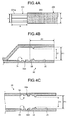
- FIG. 4A illustrates a configuration of an insulated wire to be crimp-connected to the crimp terminal 10.
- an insulated wire 200 includes an aluminum core wire 201 as a conductor portion and an insulating cover 202 covering the aluminum core wire 201.
- the insulating cover 202 in an end area is removed to form an electric-wire-exposed part 201a as an exposed conductor portion.
- a indicates a length of the electric-wire-exposed part 201a
- "b” indicates an outer diameter of the aluminum core wire 201 (electric-wire-exposed part 201a)
- c indicates an outer diameter of the insulated wire 200 (i.e. b ⁇ c).
- FIG. 4B is an X-Z cross sectional view of the crimping portion 30 of the crimp terminal 10.
- FIG. 4C is an X-Y cross sectional view of the crimping portion 30 of the crimp terminal.
- E1 indicates an inner diameter of a rear end portion of the cover crimping range 30a, as an end portion into which the insulated wire 200 is inserted, of the crimping portion 30 in the X direction
- "D1" indicates an inner diameter (the smallest inner diameter) formed by the guide section 33.
- the inner diameter D1 is, for example, 2.5 mm
- the inner diameter E1 is, for example, 3.1 mm.
- A1 indicates a length between a rear end portion of the cover crimping range 30a, in the X direction as an end portion into which the insulated wire 200 is inserted, and an end portion of an electric-wire-locking groove 34a, at the side of the cover crimping range 30a, that is the closest to the rear end portion among the electric-wire-locking grooves 34.
- the border between the area in which the electric-wire-exposed part 201a is crimped and the area of which diameter is reduced at the sealed side in the hollow cylindrical shape in cross section coincides approximately with a position at which an electric wire is inserted and disposed and at which the end of the electric-wire-exposed part 201a reaches.
- the length A1 is, for example, 4.2 mm.
- FIGS. 5A and 5B are perspective views showing respectively states of prior to and subsequent to crimping and connecting an insulated wire to the crimp terminal shown in FIG. 1 . As shown in FIGS.
- the crimping portion 30 crimps, and covers integrally, from the end 201aa of the electric-wire-exposed part 201a to a somewhat backward relative to the cover end 202a of the insulating cover 202.
- the crimping portion 30 crimps, in a tight contact state, the insulating cover 202 of the insulated wire 200 and a circumferential surface of the electric-wire-exposed part 201a of the aluminum core wire 201.
- the crimp-connection structural body 1 is manufactured.
- the longitudinal direction welding point W1 and the width-directional welding point W2 are welded in the crimp terminal 10 according to the first embodiment of the present invention. Therefore the insulated wire 200 in the crimped state achieves sealability against moisture, i.e., water does not permeate into a front side of the crimping portion 30 and outside of the crimping portion 30. Since the electric wire crimping range 30b is sealed by the insulating cover 202 of the insulated wire 200 and the guide section 33 shown in FIGS. 4B and 4C , sealability against moisture from backward of the crimping portion 30 is also improved. Hereby water does not contact a portion at which the electric-wire-exposed part 201a of the aluminum core wire 201 of the insulated wire 200 in the crimped state makes a tight contact with an inner surface of the crimping portion 30.
- the aluminum core wire 201 is made of an aluminum-based material, and the crimping portion 30 is made of a copper-based material.
- the aluminum core wire 201 e.g., a twisted wire, a single wire, or a rectangular wire or the like to the crimping portion 30 of the crimp terminal 10 reliably and tightly.
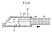
- FIG. 6 illustrates a state of inserting the insulated wire 200 into the crimping portion 30 of the crimp terminal 10.
- the length (length A1 in FIG. 4B ) between the rear end portion of the cover crimping range 30a in the X direction as the end portion into which the insulated wire 200 is inserted and an end portion of an electric-wire-locking groove 34a, at the side of the cover crimping range 30a, that is the closest to the rear end portion among the electric-wire-locking grooves 34 is longer than the length of the electric-wire-exposed part 201a (length a in FIG. 4A )(i.e., a ⁇ A1).
- the end 201aa of the electric-wire-exposed part 201a is inserted at first into the rear end portion of the cover crimping range 30a in the X direction, and the cover end 202a of the insulating cover 202 is inserted into the rear end portion of the cover crimping range 30a in the X direction before the end 201aa reaches the electric-wire-locking groove 34a.
- a central axis passing through the center of a circular cross section, which is orthogonal to the X direction, of the insulated wire 200 and being in parallel with the X-direction coincides substantially with a central axis, which is in parallel with the X direction, of the crimping portion 30.
- the insulated wire 200 is guided by the cover crimping range 30a of which inner diameter is E1, and thus, the orientation of the insulated wire 200 is regulated. As a result of that, an inclination of the insulated wire 200 decreases, and accordingly, the orientation of the insulated wire 200 becomes more suitable for an inserting operation. To be more specific, the insertion is conducted so that the central axis of the insulated wire 200 is in parallel with the longitudinal direction (X direction) of the crimping portion 30 of the crimp terminal 10.
- the end 201aa subsequent to be in the orientation suitable for insertion reaches the electric-wire-locking groove 34a, an event is prevented that the end 201aa of the electric-wire-exposed part 201a is caught by the electric-wire-locking groove 34 to be deformed.
- an operation of inserting the insulated wire 200 can be conducted stably, thus, an efficiency of a step of crimping of the insulated wire 200 is prevented from decreasing.
- a protrusive guide section 33 having a tapered section from backward to forward on a rear inner surface relative to the electric-wire-locking groove 34a may be provided. Since the tapered section is provided at the side of the cover crimping range 30a of the guide section 33, the electric-wire-exposed part 201a is inserted into the electric wire crimping range 30b more smoothly.
- E1 indicates the inner diameter of the rear end portion of the cover crimping range 30a, as an end portion into which the insulated wire 200 is inserted, of the crimping portion 30 in the X direction
- D1 indicates the inner diameter formed by the guide section 33.
- the inner diameter E1 at the rear end portion of the cover crimping range 30a in the X direction is larger than an outer diameter c of the insulated wire 200, i.e., b ⁇ c ⁇ E1.
- an outer diameter c of the insulated wire 200 i.e., b ⁇ c ⁇ E1.
- the inner diameter D1 defined by the guide section 33 of the crimping portion 30 is larger than an outer diameter b of the electric-wire-exposed part 201a, and an outer diameter c of the insulated wire 200 is larger than the inner diameter D1 (i.e., b ⁇ D1 ⁇ c). Since, hereby the cover end 202a of the insulating cover 202 enters not deeper than the guide section 33, a quality of electric connection becomes stable between the aluminum core wire 201 and the crimp terminal 10.
- a difference between the inner diameter D1 formed by the guide section 33 and the outer diameter b of the electric-wire-exposed part 201a i.e., a gap produced at the time of insertion between the guide section 33 and the electric-wire-exposed part 201a
- a difference between the inner diameter E1 of the cover crimping range 30a and the outer diameter c of the insulated wire 200 i.e., a gap produced at the time of insertion between the cover crimping range 30a and the insulating cover 202 of the insulated wire 200
- the crimp-connection structural body 1 configured as above can configure a wire harness by providing at least a combination of the crimp terminal 10 and the insulated wire 200 as shown in FIG. 5B .
- FIG. 7 is a perspective view showing a connector in which the above-configured wire harnesses are attached to a pair of connector housings.
- a crimp-connection structural body 1a using the female crimp terminal 11 as the crimp terminal 10 and the crimp-connection structural body 1b using the male crimp terminal (not shown) as the crimp terminal 10 are attached to a pair of the connector housings Hc respectively. It is possible to configure a female connector Ca and a male connector Cb having reliable conductivities by attaching the crimping structural bodies 1a and 1b to the pair of the connector housings Hc respectively.
- a wire harness 100a provided with the female connector Ca is configured by attaching the crimp-connection structural body 1a configured to have the female crimp terminal 11 to the female connector housing Hc.
- a wire harness 100b provided with the male connector Cb is configured by attaching the crimp-connection structural body 1b configured to have the male crimp terminal (not shown) to the male connector housing Hc.
- the wire harnesses 100a and 100b can be connected electrically and physically by fitting the male connector Cb to the female connector Ca along the X direction.
- FIG. 8A is a cross-sectional view of a crimping portion of a crimp terminal of a second embodiment of the present invention.
- FIG. 8B is a cross-sectional view of the crimping portion of the crimp terminal of the second embodiment of the present invention.
- FIGS. 8A and 8B are cross-sectional views corresponding to FIGS. 4B and 4C as the cross-sectional views of the crimp terminal 10.
- a box section of a crimp terminal 10A shown in FIGS. 8A and 8B has a configuration that is similar to that of the box section 20 of the crimp terminal 10 shown in FIG. 1 , and therefore, an explanation therefor is omitted.
- a crimping portion 30A shown in FIG. 8A includes a cover crimping range 30Aa, an electric wire crimping range 30Ab, and a sealing portion 30Ac.
- an inner diameter of the electric wire crimping range 30Ab is smaller than that of the cover crimping range 30Aa, and serves as a guide section (hereafter the cover crimping range 30Aa may be described as guide section 33A).
- a central axis in parallel with a cylinder being formed by the guide section 33A in the X direction coincides substantially with a central axis in parallel with a cylinder being formed by the crimping portion 30A in the X direction.
- the crimping portion 30A is provided with an electric-wire-locking groove 34A at the electric wire crimping range 30Ab (guide section 33A).
- E2 indicates an inner diameter of a rear end portion of the cover crimping range 30Aa in the X direction as an end portion into which the insulated wire 200 is inserted
- D2 indicates an inner diameter of the guide section 33A.
- the inner diameter D2 is, for example, 2.5 mm
- the inner diameter E2 is, for example, 3.1 mm.
- A2 indicates a length between the rear end portion of the cover crimping range 30Aa in the X direction as the end portion into which the insulated wire 200 is inserted and an end portion of an electric-wire-locking groove 34Aa, at the side of the cover crimping range 30Aa, that is the closest to the rear end portion among the electric-wire-locking grooves 34A.
- the length A2 is, for example, 4.2 mm.
- the inner diameter E2 of the rear end portion of the cover crimping range 30Aa in the X direction is larger than the outer diameter c of the insulated wire 200, i.e., b ⁇ c ⁇ E2.
- the length A2 between the rear end portion of the cover crimping range 30Aa in the X direction and an end portion of the electric-wire-locking groove 34Aa at the side of the cover crimping range 30Aa is larger than the length a of the electric-wire-exposed part 201a (i.e., a ⁇ A2).
- the end 201aa of the electric-wire-exposed part 201a is inserted into the rear end portion of the cover crimping range 30Aa in the X direction at first, and the cover end 202a of the insulating cover 202 is inserted into the rear end portion of the cover crimping range 30Aa in the X direction before the end 201aa reaches an electric-wire-locking groove 34Aa.
- a central axis of the insulated wire 200 coincides substantially with a central axis which is in parallel with the X direction of the crimping portion 30A. After that, the end 201aa reaches the electric-wire-locking groove 34Aa.
- the insulated wire 200 is guided by the cover crimping range 30Aa of which inner diameter is E2, and thus, the orientation of the insulated wire 200 is regulated. As a result, the orientation of the insulated wire 200 becomes less inclined, thus more suitable for an inserting operation. Since the end 201aa having been in the orientation suitable for insertion reaches the electric-wire-locking groove 34Aa, an event is prevented that the end 201aa of the electric-wire-exposed part 201a is caught by the electric-wire-locking groove 34A to be deformed. Hereby, an operation of inserting the insulated wire 200 can be conducted stably, thus, an efficiency of a step of crimping of the insulated wire 200 is prevented from decreasing.
- an angle ⁇ defined by the tapered section of the guide section 33A relative to the X direction is equal to or smaller than 45°.
- the inner diameter D2 of the guide section 33A is larger than the outer diameter b of the electric-wire-exposed part 201a, and the outer diameter c of the insulated wire 200 is larger than the inner diameter D2 (i.e., b ⁇ D2 ⁇ c). Since, hereby the cover end 202a of the insulating cover 202 enters not deeper than the guide section 33A, a quality of electric connection becomes stable between the aluminum core wire 201 and the crimp terminal 10A.
- a difference between the inner diameter D2 formed by the guide section 33A and the outer diameter b of the electric-wire-exposed part 201a is larger than a difference between the inner diameter E2 of the cover crimping range 30Aa and the outer diameter c of the insulated wire 200 (i.e., E2-c ⁇ D2-b).
- FIG. 9 is a cross-sectional view showing another example of the crimp terminal 10A of the second embodiment.
- the crimp terminal 10A includes a box section 20A and a crimping portion 30A.
- the box section 20A has a shape of hollow quadrangular prism.
- An insertion tab included in a male crimp terminal is inserted into the box section 20A from a front end side toward a rear end in the longitudinal direction X.
- the crimping portion 30A has an approximate O-shape in rear view and is provided at the back of the box section 20A via a predetermined length of transition section 40A.
- the box section 20A is provided with an elastic contact piece 21A being bent backward in the longitudinal direction X and contacting the insertion tab of the male crimp terminal.
- the box section 20A is configured to be of an approximate rectangular shape viewed in front in the longitudinal direction X by bending side parts 23A to overlap each other.
- the crimp terminal 10A has a shift-neck portion 41 in which a connection portion of a part between the sealing portion 30Ac and the transition section 40A is shifted to a side of a central axis O of the crimping portion 30A relative to a bottom surface of the electric wire crimping range 30Ab. Since an area inclining in a bent part is shorter than that of the crimp terminal 10 according to the first embodiment by providing the shift-neck portion 41, the entire length along the longitudinal direction X can be decreased; thus, the crimp terminal 10A can be downsized. Since the connection portion of the shift-neck portion 41 is bent, an act of support occurs at the connection portion.
- the shift-neck portion 41 is supported even if external forces are applied in a vertical direction (Z direction) and in a lateral direction (Y direction), strength thereof can be increased.
- Other configurations are similar to that of the crimp terminal 10A according to the second embodiment, explanations therefor will be omitted.
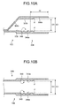
- FIG. 10A is a cross-sectional view of a crimping portion of a crimp terminal of a third embodiment of the present invention.
- FIG. 10B is a cross-sectional view of the crimping portion of the crimp terminal of the third embodiment.
- FIGS. 10A and 10B are cross-sectional views corresponding to FIGS. 8B and 8 .
- the box section of the crimp terminal 10B shown in FIGS. 10A and 10B has a configuration which is similar to that of the box section 20 of the crimp terminal 10 shown in FIG. 1 , explanation therefor will be omitted.
- a crimping portion 30B includes a cover crimping range 30Ba, an electric wire crimping range 30Bb, and a sealing portion 30Bc.
- a thickness of the electric wire crimping range 30Bb is larger than a thickness of the cover crimping range 30Ba.
- the electric wire crimping range 30Bb serves as a guide section (hereafter the cover crimping range 30Ba may be described as guide section 33B).
- the crimping portion 30B is provided with an electric-wire-locking groove 34B at the electric wire crimping range 30Bb (guide section 33B).
- E3 indicates an inner diameter of a rear end portion of the cover crimping range 30Ba, as an end portion into which the insulated wire 200 is inserted, of the crimping portion 30B in the X direction
- D3 indicates an inner diameter of the guide section 33B.
- the inner diameter D3 is, for example, 2.5 mm
- the inner diameter E3 is, for example, 3.1 mm.
- A3 indicates a length between a rear end portion of the cover crimping range 30Ba in the X direction as an end portion into which the insulated wire 200 is inserted, and an end portion of an electric-wire-locking groove 34Ba, at the side of the cover crimping range 30Ba, that is the closest to the rear end portion among the electric-wire-locking grooves 34B.
- the length A3 is, for example, 4.2 mm.
- the inner diameter E3 of the rear end portion of the cover crimping range 30Ba in the X direction is larger than the outer diameter c of the insulated wire 200, i.e., b ⁇ c ⁇ E3.
- the length A3 between the rear end portion of the cover crimping range 30Ba in the X direction and the end portion of the electric-wire-locking groove 34Ba at the side of the cover crimping range 30Ba is larger than the length a of the electric-wire-exposed part 201a (i.e., a ⁇ A3).
- the end 201aa of the electric-wire-exposed part 201a is inserted at first into the rear end portion of the cover crimping range 30Ba in the X direction, and the cover end 202a of the insulating cover 202 is inserted into the rear end portion of the cover crimping range 30Ba in the X direction before the end 201aa reaches the electric-wire-locking groove 34Ba.
- a central axis of the insulated wire 200 coincides substantially with a central axis which is in parallel with the X direction of the crimping portion 30B. After that, the end 201aa reaches the electric-wire-locking groove 34Ba.
- the insulated wire 200 is guided by the cover crimping range 30Ba of which inner diameter is E3, and thus, the orientation of the insulated wire 200 is regulated. As a result of that, the orientation of the insulated wire 200 becomes less inclined and thus more suitable for an inserting operation.
- the end 201aa subsequent to be in the orientation suitable for insertion reaches the electric-wire-locking groove 34Ba, an event is prevented that the end 201aa of the electric-wire-exposed part 201a is caught by the electric-wire-locking groove 34B to be deformed.
- an operation of inserting the insulated wire 200 can be conducted stably, thus, an efficiency of a step of crimping of the insulated wire 200 is restrained from decreasing.
- an angle ⁇ defined by the tapered section of the guide section 33B relative to the X direction is equal to or smaller than 45°.
- the inner diameter D3 of the guide section 33B is larger than the outer diameter b of the electric-wire-exposed part 201a, and the outer diameter c of the insulated wire 200 is larger than the inner diameter D3 (i.e., b ⁇ D3 ⁇ c). Since, hereby the cover end 202a of the insulating cover 202 enters not deeper than the guide section 33B, a quality of electric connection becomes stable between the aluminum core wire 201 and the crimp terminal 10B.
- a difference between the inner diameter D3 formed by the guide section 33B and the outer diameter b of the electric-wire-exposed part 201a is larger than a difference between the inner diameter E3 of the cover crimping range 30Ba and the outer diameter c of the insulated wire 200 (i.e., E3-c ⁇ D3-b).
- a compressibility ratio (a value obtained by dividing a cross sectional area after crimping by a cross sectional area prior to crimping) at a time of crimping can be maintained to a large degree by increasing the thickness of the electric wire crimping range 30Bb, damage or deformation of a terminal due to an excessive force can be prevented.
- a positional relationship between the crimping portion 30B and the insulated wire 200 in an operation of insertion it is possible to achieve a stable sealability of the crimped crimp terminal 10B against moisture.
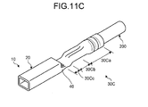
- FIGS. 11A, 11B , and 11C are perspective views showing a method of welding a crimping portion by a method for manufacturing the crimp terminal according to the fourth embodiment.
- the fourth embodiment a welding is conducted so that a longitudinal direction welding point W3 varies in a height direction.
- the crimping portion 30 having a sealability against moisture can be configured in various shapes, e.g., the crimp terminal 10A or the like having the shift-neck portion 41 described in the modification example of the second embodiment can be manufactured.
- a copper alloy strip as a plate material is punched by press molding into a shape of a terminal as shown in FIG. 11A , then the punched copper alloy strip is rolled, and a front end portion thereof in the longitudinal direction X is crushed to form a shape of the crimping portion 30C including the sealing portion 30Cc in advance.
- Fiber laser welding is conducted to both of facing end sections 32Ca, which are to be rolled and butted, along a longitudinal direction welding point W3 in the longitudinal direction X, and a sealing portion 30Cc is welded, and sealed, along a width-directional welding point W4 in the width direction Y.
- the crimping portion 30C is finished as described above.
- FIGS. 2A , 2B, and 2C since the above-described sequence of steps of fiber laser welding are conducted to the stick terminal 10 according to the first embodiment in a so-called cut-open-back state, the crimp terminal 10 must be reversed in a production process.
- the fourth embodiment as shown in FIGS.
- the crimp terminal 10 can be manufactured in the above-described sequential process from press molding to the fiber laser welding without being reversed. Therefore, a manufacturing process can be simplified, and thus mass production, e.g., several hundreds of pieces per minute of crimp terminals can be achieved, a low-cost production can be intended.
- both the facing end sections 32Ca may be butted and sealed at a bottom surface side of the crimping portion 30C.
- both the facing end sections 32Ca may be butted and sealed at an upper surface side of the crimping portion 30C.
- a cover crimping range 30Ca of the crimping portion 30C is crimped against the insulating cover 202 of the insulated wire 200 in a circular shape in front view, and an electric wire crimping range 30Cb may be crimped against the aluminum core wire 201 in an approximate round-U shape in front view in the crimped state.
- the crimping portion 30C may be welded to the crimp terminal 10 while the crimp terminal 10 is attached to a belt-shaped carrier K, and then the crimp terminal 10 may be separated from the carrier K when, or after, the insulated wire 200 is crimp-connected.
- the crimp terminal 10 may be formed in a separated state from the carrier K, and then, the insulated wire 200 may be crimp-connected.
- a crimp terminal 10 capable of realizing a crimped state having little gap and high sealability against moisture in a state where the aluminum core wire 201 is inserted into, and crimped to, the crimping portion 30C. Therefore, it is possible to produce the crimp terminal 10 such as a female crimp terminal or the like capable of realizing a crimped state in which there is little gap and sealability against moisture is high even if a diameter of the aluminum core wire 201 is small.
- the crimping portion 30 of the crimp terminal 10 is crimp-connected to the aluminum core wire 201 made of aluminum or aluminum alloy
- other metals may be used to a core wire, for example, a metal conductor made of copper (Cu) or Cu alloy or the like or a copper-clad aluminum wire (CA wire) or the like in which copper is disposed around an outer periphery of an aluminum wire can be used.
- lasers such as YAG laser or CO 2 laser other than fiber laser welding may be used for welding under a predetermined condition.
- the present invention can be used for a crimp terminal crimping an insulated wire thereto, a crimp-connection structural body in which an insulated wire is crimp-connected to a crimp terminal, and a method for manufacturing a crimp-connection structural body preferably, and can be used for a crimp terminal and a crimp-connection structural body and a method for manufacturing a crimp-connection structural body which require a high sealability against moisture more preferably.
Applications Claiming Priority (2)
| Application Number | Priority Date | Filing Date | Title |
|---|---|---|---|
| JP2013033874 | 2013-02-22 | ||
| PCT/JP2013/084411 WO2014129080A1 (ja) | 2013-02-22 | 2013-12-24 | 圧着端子、圧着接続構造体及び圧着接続構造体の製造方法 |
Publications (2)
| Publication Number | Publication Date |
|---|---|
| EP2808947A1 true EP2808947A1 (de) | 2014-12-03 |
| EP2808947A4 EP2808947A4 (de) | 2015-01-07 |
Family
ID=51390891
Family Applications (1)
| Application Number | Title | Priority Date | Filing Date |
|---|---|---|---|
| EP13875327.2A Withdrawn EP2808947A4 (de) | 2013-02-22 | 2013-12-24 | Crimpklemme, crimpverbindungsstruktur und verfahren zur herstellung einer crimpverbindungsstruktur |
Country Status (6)
| Country | Link |
|---|---|
| US (1) | US9118123B2 (de) |
| EP (1) | EP2808947A4 (de) |
| JP (1) | JP5567237B1 (de) |
| KR (1) | KR101477727B1 (de) |
| CN (1) | CN104170167B (de) |
| WO (1) | WO2014129080A1 (de) |
Families Citing this family (11)
| Publication number | Priority date | Publication date | Assignee | Title |
|---|---|---|---|---|
| WO2014010605A1 (ja) * | 2012-07-09 | 2014-01-16 | 古河電気工業株式会社 | 圧着端子、接続構造体及びコネクタ |
| JP5957345B2 (ja) * | 2012-09-06 | 2016-07-27 | 矢崎総業株式会社 | 接続構造 |
| KR101493205B1 (ko) * | 2013-02-22 | 2015-02-12 | 후루카와 덴키 고교 가부시키가이샤 | 압착 단자의 제조 방법, 압착 단자 및 와이어 하네스 |
| CN104969415B (zh) * | 2013-02-23 | 2018-05-29 | 古河电气工业株式会社 | 压接端子、压接端子的制造方法、电线连接结构体和电线连接结构体的制造方法 |
| JP6020436B2 (ja) * | 2013-12-16 | 2016-11-02 | 住友電装株式会社 | 電線接続用の端子および該端子の電線接続構造 |
| JP6452344B2 (ja) * | 2014-08-19 | 2019-01-16 | 古河電気工業株式会社 | 圧着端子、接続構造体、コネクタ、ワイヤーハーネス、並びに圧着端子の製造方法及び接続構造体の製造方法 |
| JP6678587B2 (ja) * | 2014-08-22 | 2020-04-08 | 古河電気工業株式会社 | 圧着端子、接続構造体、圧着端子の製造方法及びレーザ溶接方法 |
| US10965113B2 (en) * | 2017-04-12 | 2021-03-30 | Sumitomo Wiring Systems, Ltd. | Wire harness |
| JP7052665B2 (ja) * | 2018-10-02 | 2022-04-12 | 株式会社オートネットワーク技術研究所 | 雌端子 |
| CN109870778A (zh) * | 2018-12-12 | 2019-06-11 | 金华八达集团有限公司科技信息分公司 | 一种带定位和湿度检测功能的光缆接头盒 |
| WO2024022815A1 (en) * | 2022-07-28 | 2024-02-01 | Huber+Suhner Ag | Crimp contact |
Citations (7)
| Publication number | Priority date | Publication date | Assignee | Title |
|---|---|---|---|---|
| JP2004071437A (ja) * | 2002-08-08 | 2004-03-04 | Sumitomo Wiring Syst Ltd | 自動車用アース端子と電線の防水接続構造 |
| US20040168315A1 (en) * | 2002-12-20 | 2004-09-02 | Yazaki Corporation | Method of connecting terminal and electric wire |
| US20080076284A1 (en) * | 2006-09-07 | 2008-03-27 | Sony Corporation | Fluorescent tube connector device, light source device, and display |
| JP2009176537A (ja) * | 2008-01-23 | 2009-08-06 | Yazaki Corp | アルミニウム電線と端子との圧着構造 |
| EP2200121A1 (de) * | 2008-12-16 | 2010-06-23 | Sumitomo Wiring Systems, Ltd. | Drahtverbindungshülse, Herstellungsverfahren für Drahtverbindungshülse, durch Crimpen mit einer Drahtverbindungshülse vorverbundener Reparaturdraht sowie Verbindungsverfahren |
| EP2555328A1 (de) * | 2010-03-30 | 2013-02-06 | Furukawa Electric Co., Ltd. | Crimp-klemme, verbindungsstrukturkörper und konnektor |
| WO2014014104A1 (ja) * | 2012-07-20 | 2014-01-23 | 古河電気工業株式会社 | 圧着端子、接続構造体及びコネクタ |
Family Cites Families (44)
| Publication number | Priority date | Publication date | Assignee | Title |
|---|---|---|---|---|
| US2493311A (en) * | 1944-11-20 | 1950-01-03 | Honeywell Regulator Co | Electric temperature sensing device |
| US2685076A (en) * | 1951-05-05 | 1954-07-27 | Aircraft Marine Prod Inc | Electrical connector |
| US2724098A (en) * | 1952-04-09 | 1955-11-15 | Thomas & Betts Corp | Electric connectors |
| BE529586A (de) * | 1953-06-12 | |||
| US2981787A (en) * | 1958-02-07 | 1961-04-25 | Burndy Corp | Insulated connector |
| US3955044A (en) * | 1970-12-03 | 1976-05-04 | Amp Incorporated | Corrosion proof terminal for aluminum wire |
| US3999273A (en) * | 1975-07-30 | 1976-12-28 | Ark-Les Switch Corporation | Insulated wire splice machine |
| JP2527893Y2 (ja) * | 1989-08-22 | 1997-03-05 | 株式会社 ニチフ端子工業 | 被覆スリーブ付き棒型圧着端子 |
| JPH0381983A (ja) * | 1989-08-24 | 1991-04-08 | Nippon Chemicon Corp | 電子部品の製造方法および製造装置 |
| JPH078970U (ja) * | 1993-07-06 | 1995-02-07 | 住友電装株式会社 | ゴム栓付き端子圧着電線 |
| JPH097649A (ja) * | 1995-06-15 | 1997-01-10 | Japan Aviation Electron Ind Ltd | 圧着コンタクト |
| US5749756A (en) * | 1995-10-27 | 1998-05-12 | The Whitaker Corporation | Sealed corrosion-proof crimped terminal of splice |
| DE19549174A1 (de) * | 1995-10-28 | 1997-07-03 | Bosch Gmbh Robert | Kontaktelement mit Crimpabschnitt |
| US5667413A (en) * | 1995-11-13 | 1997-09-16 | Alcoa Fujikura Ltd. | Socket-type electrical connector |
| JPH10328862A (ja) * | 1997-06-05 | 1998-12-15 | Harness Sogo Gijutsu Kenkyusho:Kk | レーザ溶接方法 |
| JP2000299140A (ja) * | 1999-04-15 | 2000-10-24 | Yazaki Corp | 電線と接続端子の接続方法及び接続構造 |
| JP3718394B2 (ja) * | 1999-12-09 | 2005-11-24 | 矢崎総業株式会社 | 被覆電線の端末接続部およびその防水処理方法と装置 |
| JP2002124310A (ja) * | 2000-10-13 | 2002-04-26 | Yazaki Corp | 被覆電線の端子取付構造及び端子取付方法 |
| JP2002216862A (ja) * | 2001-01-19 | 2002-08-02 | Yazaki Corp | 端子と電線の接続部の防水構造及び防水方法 |
| JP2004273135A (ja) * | 2003-03-05 | 2004-09-30 | Sumitomo Wiring Syst Ltd | コネクタ |
| JP2006147248A (ja) * | 2004-11-17 | 2006-06-08 | Auto Network Gijutsu Kenkyusho:Kk | 防水コネクタ |
| US7260891B2 (en) * | 2005-01-13 | 2007-08-28 | Siemens Vdo Automotive Corporation | Connector overmold spacer |
| JP4846435B2 (ja) * | 2006-05-10 | 2011-12-28 | 矢崎総業株式会社 | 端子金具及び取付方法 |
| JP4499114B2 (ja) * | 2007-01-25 | 2010-07-07 | タイコエレクトロニクスジャパン合同会社 | 端子圧着方法、端子圧着装置、端子圧着構造及び電気コネクタ |
| FR2920599B1 (fr) * | 2007-09-05 | 2009-12-18 | Mecatraction | Cosse pour connexion electrique et son procede d'assemblage. |
| JP5107693B2 (ja) * | 2007-12-21 | 2012-12-26 | タイコエレクトロニクスジャパン合同会社 | 圧着構造及び圧着方法 |
| JP5072098B2 (ja) * | 2008-01-24 | 2012-11-14 | 矢崎総業株式会社 | 圧着端子 |
| US7663059B2 (en) * | 2008-02-21 | 2010-02-16 | Yazaki Corporation | Cap and manufacturing method of the cap |
| JP2010244895A (ja) * | 2009-04-07 | 2010-10-28 | Hitachi Cable Ltd | アルミニウム導体用圧縮接続端子とその接続方法 |
| US8360803B2 (en) * | 2009-09-18 | 2013-01-29 | Delphi Technologies, Inc. | Electrical terminal connection with molded seal |
| US7905755B1 (en) * | 2009-09-18 | 2011-03-15 | Delphi Technologies, Inc. | Electrical terminal connection with sealed core crimp |
| US7954235B2 (en) * | 2009-09-18 | 2011-06-07 | Delphi Technologies, Inc. | Method of making a seal about a copper-based terminal |
| JP5495203B2 (ja) * | 2009-09-24 | 2014-05-21 | 矢崎総業株式会社 | 圧着部の防水処理方法 |
| CN102782940B (zh) * | 2010-02-05 | 2015-11-25 | 古河电气工业株式会社 | 连接构造体 |
| JP5375687B2 (ja) * | 2010-03-15 | 2013-12-25 | 株式会社オートネットワーク技術研究所 | 端子金具、及び端子金具付き電線 |
| JP2011198655A (ja) * | 2010-03-19 | 2011-10-06 | Yazaki Corp | 圧着端子の電線に対する接続構造 |
| JP5557378B2 (ja) * | 2010-03-23 | 2014-07-23 | 矢崎総業株式会社 | 圧着端子および圧着端子の電線に対する圧着構造 |
| JP5606127B2 (ja) * | 2010-04-01 | 2014-10-15 | 矢崎総業株式会社 | 圧着端子の電線に対する接続構造 |
| JP5242625B2 (ja) | 2010-04-27 | 2013-07-24 | 古河電気工業株式会社 | 接続構造体及び接続構造体の製造方法 |
| US8210884B2 (en) * | 2010-10-18 | 2012-07-03 | Tyco Electronics Corporation | Electrical terminal for terminating a wire |
| EP2650972B1 (de) * | 2010-12-08 | 2016-03-16 | Furukawa Electric Co., Ltd. | Crimpklemme, verbindungsstruktur und herstellungsverfahren dafür |
| KR20140134329A (ko) * | 2012-03-30 | 2014-11-21 | 야자키 소교 가부시키가이샤 | 단자 크림핑된 와이어 |
| JP5953591B2 (ja) * | 2012-04-05 | 2016-07-20 | 矢崎総業株式会社 | 圧着端子を電線に圧着する方法 |
| CN104145374A (zh) * | 2013-02-22 | 2014-11-12 | 古河电气工业株式会社 | 压接端子、压接连接结构体及压接连接结构体的制造方法 |
-
2013
- 2013-12-24 WO PCT/JP2013/084411 patent/WO2014129080A1/ja active Application Filing
- 2013-12-24 EP EP13875327.2A patent/EP2808947A4/de not_active Withdrawn
- 2013-12-24 JP JP2014507791A patent/JP5567237B1/ja active Active
- 2013-12-24 CN CN201380013613.2A patent/CN104170167B/zh active Active
- 2013-12-24 KR KR1020147025684A patent/KR101477727B1/ko active IP Right Grant
-
2014
- 2014-09-09 US US14/481,293 patent/US9118123B2/en active Active
Patent Citations (7)
| Publication number | Priority date | Publication date | Assignee | Title |
|---|---|---|---|---|
| JP2004071437A (ja) * | 2002-08-08 | 2004-03-04 | Sumitomo Wiring Syst Ltd | 自動車用アース端子と電線の防水接続構造 |
| US20040168315A1 (en) * | 2002-12-20 | 2004-09-02 | Yazaki Corporation | Method of connecting terminal and electric wire |
| US20080076284A1 (en) * | 2006-09-07 | 2008-03-27 | Sony Corporation | Fluorescent tube connector device, light source device, and display |
| JP2009176537A (ja) * | 2008-01-23 | 2009-08-06 | Yazaki Corp | アルミニウム電線と端子との圧着構造 |
| EP2200121A1 (de) * | 2008-12-16 | 2010-06-23 | Sumitomo Wiring Systems, Ltd. | Drahtverbindungshülse, Herstellungsverfahren für Drahtverbindungshülse, durch Crimpen mit einer Drahtverbindungshülse vorverbundener Reparaturdraht sowie Verbindungsverfahren |
| EP2555328A1 (de) * | 2010-03-30 | 2013-02-06 | Furukawa Electric Co., Ltd. | Crimp-klemme, verbindungsstrukturkörper und konnektor |
| WO2014014104A1 (ja) * | 2012-07-20 | 2014-01-23 | 古河電気工業株式会社 | 圧着端子、接続構造体及びコネクタ |
Non-Patent Citations (1)
| Title |
|---|
| See also references of WO2014129080A1 * |
Also Published As
| Publication number | Publication date |
|---|---|
| CN104170167A (zh) | 2014-11-26 |
| US9118123B2 (en) | 2015-08-25 |
| KR101477727B1 (ko) | 2014-12-30 |
| WO2014129080A1 (ja) | 2014-08-28 |
| US20140377991A1 (en) | 2014-12-25 |
| KR20140116976A (ko) | 2014-10-06 |
| JP5567237B1 (ja) | 2014-08-06 |
| JPWO2014129080A1 (ja) | 2017-02-02 |
| EP2808947A4 (de) | 2015-01-07 |
| CN104170167B (zh) | 2016-01-27 |
Similar Documents
| Publication | Publication Date | Title |
|---|---|---|
| EP2808948A1 (de) | Crimpklemme, crimpverbindungsstruktur und verfahren zur herstellung einer crimpverbindungsstruktur | |
| EP2808947A1 (de) | Crimpklemme, crimpverbindungsstruktur und verfahren zur herstellung einer crimpverbindungsstruktur | |
| EP2871718B1 (de) | Druckfixierbarer anschluss, verbindungsstruktur und verbinder | |
| EP2960991B1 (de) | Verbindungsband für anschlussklemme, verfahren zur herstellung einer gecrimpten anschlussklemme, drahtcrimpvorrichtung und drahtcrimpverfahren | |
| US20110028034A1 (en) | Hoop material, method of making inner conductor terminal, and coaxial connector | |
| EP2876731B1 (de) | Crimpklemme | |
| EP2606536B1 (de) | Elektrische steckerklemme | |
| CN109616808B (zh) | 大电流电连接器 | |
| JP2019215969A (ja) | 接続端子及び端子接続構造 | |
| JP2020145190A (ja) | 接続端子、接続端子を使用してワイヤを接続する方法、および押型 | |
| KR20100016429A (ko) | 수형 전기 단자 | |
| JP4800066B2 (ja) | 接続部材 | |
| JP6200366B2 (ja) | 接続構造体、ワイヤーハーネス、及び接続構造体の製造方法 | |
| JP5151936B2 (ja) | 端子金具及びその製造方法 | |
| KR102338051B1 (ko) | 동축 커넥터 및 동축 케이블을 구비한 동축 커넥터 | |
| EP4064459B1 (de) | Mit klemmen ausgestatteter elektrischer draht | |
| JP5195191B2 (ja) | 端子金具及び端子金具付き電線 | |
| WO2014129605A1 (ja) | 接続構造体の製造方法、接続構造体、及び圧着装置 | |
| JP6133078B2 (ja) | 圧着端子及びその製造方法 | |
| JP2021190409A (ja) | アルミ電線と端子金具との圧着構造 | |
| JP6522872B2 (ja) | 圧着端子、接続構造体、コネクタ及び、接続構造体の製造方法 | |
| JP2023161251A (ja) | 端子付き電線 |
Legal Events
| Date | Code | Title | Description |
|---|---|---|---|
| PUAI | Public reference made under article 153(3) epc to a published international application that has entered the european phase |
Free format text: ORIGINAL CODE: 0009012 |
|
| 17P | Request for examination filed |
Effective date: 20140826 |
|
| AK | Designated contracting states |
Kind code of ref document: A1 Designated state(s): AL AT BE BG CH CY CZ DE DK EE ES FI FR GB GR HR HU IE IS IT LI LT LU LV MC MK MT NL NO PL PT RO RS SE SI SK SM TR |
|
| A4 | Supplementary search report drawn up and despatched |
Effective date: 20141204 |
|
| RIC1 | Information provided on ipc code assigned before grant |
Ipc: H01R 4/18 20060101AFI20141128BHEP Ipc: H01R 4/62 20060101ALI20141128BHEP Ipc: H01R 4/20 20060101ALI20141128BHEP Ipc: H01R 43/02 20060101ALI20141128BHEP |
|
| STAA | Information on the status of an ep patent application or granted ep patent |
Free format text: STATUS: THE APPLICATION HAS BEEN WITHDRAWN |
|
| 18W | Application withdrawn |
Effective date: 20150423 |