EP2806154A1 - Hydraulikmotor - Google Patents
Hydraulikmotor Download PDFInfo
- Publication number
- EP2806154A1 EP2806154A1 EP13752104.3A EP13752104A EP2806154A1 EP 2806154 A1 EP2806154 A1 EP 2806154A1 EP 13752104 A EP13752104 A EP 13752104A EP 2806154 A1 EP2806154 A1 EP 2806154A1
- Authority
- EP
- European Patent Office
- Prior art keywords
- motor
- passage
- casing
- chamber
- hydraulic
- Prior art date
- Legal status (The legal status is an assumption and is not a legal conclusion. Google has not performed a legal analysis and makes no representation as to the accuracy of the status listed.)
- Granted
Links
Images



Classifications
-
- F—MECHANICAL ENGINEERING; LIGHTING; HEATING; WEAPONS; BLASTING
- F03—MACHINES OR ENGINES FOR LIQUIDS; WIND, SPRING, OR WEIGHT MOTORS; PRODUCING MECHANICAL POWER OR A REACTIVE PROPULSIVE THRUST, NOT OTHERWISE PROVIDED FOR
- F03C—POSITIVE-DISPLACEMENT ENGINES DRIVEN BY LIQUIDS
- F03C1/00—Reciprocating-piston liquid engines
- F03C1/22—Reciprocating-piston liquid engines with movable cylinders or cylinder
- F03C1/24—Reciprocating-piston liquid engines with movable cylinders or cylinder in which the liquid exclusively displaces one or more pistons reciprocating in rotary cylinders
- F03C1/2407—Reciprocating-piston liquid engines with movable cylinders or cylinder in which the liquid exclusively displaces one or more pistons reciprocating in rotary cylinders having cylinders in star or fan arrangement, the connection of the pistons with an actuated element being at the outer ends of the cylinders
- F03C1/2415—Reciprocating-piston liquid engines with movable cylinders or cylinder in which the liquid exclusively displaces one or more pistons reciprocating in rotary cylinders having cylinders in star or fan arrangement, the connection of the pistons with an actuated element being at the outer ends of the cylinders cylinder block and actuated cam both rotating
-
- F—MECHANICAL ENGINEERING; LIGHTING; HEATING; WEAPONS; BLASTING
- F03—MACHINES OR ENGINES FOR LIQUIDS; WIND, SPRING, OR WEIGHT MOTORS; PRODUCING MECHANICAL POWER OR A REACTIVE PROPULSIVE THRUST, NOT OTHERWISE PROVIDED FOR
- F03C—POSITIVE-DISPLACEMENT ENGINES DRIVEN BY LIQUIDS
- F03C1/00—Reciprocating-piston liquid engines
- F03C1/02—Reciprocating-piston liquid engines with multiple-cylinders, characterised by the number or arrangement of cylinders
- F03C1/06—Reciprocating-piston liquid engines with multiple-cylinders, characterised by the number or arrangement of cylinders with cylinder axes generally coaxial with, or parallel or inclined to, main shaft axis
- F03C1/0636—Reciprocating-piston liquid engines with multiple-cylinders, characterised by the number or arrangement of cylinders with cylinder axes generally coaxial with, or parallel or inclined to, main shaft axis having rotary cylinder block
- F03C1/0644—Component parts
- F03C1/0663—Casings, housings
-
- F—MECHANICAL ENGINEERING; LIGHTING; HEATING; WEAPONS; BLASTING
- F01—MACHINES OR ENGINES IN GENERAL; ENGINE PLANTS IN GENERAL; STEAM ENGINES
- F01B—MACHINES OR ENGINES, IN GENERAL OR OF POSITIVE-DISPLACEMENT TYPE, e.g. STEAM ENGINES
- F01B1/00—Reciprocating-piston machines or engines characterised by number or relative disposition of cylinders or by being built-up from separate cylinder-crankcase elements
- F01B1/06—Reciprocating-piston machines or engines characterised by number or relative disposition of cylinders or by being built-up from separate cylinder-crankcase elements with cylinders in star or fan arrangement
- F01B1/0641—Details, component parts specially adapted for such machines
- F01B1/0672—Draining of the machine housing; arrangements dealing with leakage fluid
-
- F—MECHANICAL ENGINEERING; LIGHTING; HEATING; WEAPONS; BLASTING
- F01—MACHINES OR ENGINES IN GENERAL; ENGINE PLANTS IN GENERAL; STEAM ENGINES
- F01B—MACHINES OR ENGINES, IN GENERAL OR OF POSITIVE-DISPLACEMENT TYPE, e.g. STEAM ENGINES
- F01B3/00—Reciprocating-piston machines or engines with cylinder axes coaxial with, or parallel or inclined to, main shaft axis
- F01B3/0032—Reciprocating-piston machines or engines with cylinder axes coaxial with, or parallel or inclined to, main shaft axis having rotary cylinder block
- F01B3/0044—Component parts, details, e.g. valves, sealings, lubrication
- F01B3/007—Swash plate
-
- F—MECHANICAL ENGINEERING; LIGHTING; HEATING; WEAPONS; BLASTING
- F03—MACHINES OR ENGINES FOR LIQUIDS; WIND, SPRING, OR WEIGHT MOTORS; PRODUCING MECHANICAL POWER OR A REACTIVE PROPULSIVE THRUST, NOT OTHERWISE PROVIDED FOR
- F03C—POSITIVE-DISPLACEMENT ENGINES DRIVEN BY LIQUIDS
- F03C1/00—Reciprocating-piston liquid engines
- F03C1/02—Reciprocating-piston liquid engines with multiple-cylinders, characterised by the number or arrangement of cylinders
- F03C1/06—Reciprocating-piston liquid engines with multiple-cylinders, characterised by the number or arrangement of cylinders with cylinder axes generally coaxial with, or parallel or inclined to, main shaft axis
- F03C1/0636—Reciprocating-piston liquid engines with multiple-cylinders, characterised by the number or arrangement of cylinders with cylinder axes generally coaxial with, or parallel or inclined to, main shaft axis having rotary cylinder block
- F03C1/0644—Component parts
-
- F—MECHANICAL ENGINEERING; LIGHTING; HEATING; WEAPONS; BLASTING
- F03—MACHINES OR ENGINES FOR LIQUIDS; WIND, SPRING, OR WEIGHT MOTORS; PRODUCING MECHANICAL POWER OR A REACTIVE PROPULSIVE THRUST, NOT OTHERWISE PROVIDED FOR
- F03C—POSITIVE-DISPLACEMENT ENGINES DRIVEN BY LIQUIDS
- F03C1/00—Reciprocating-piston liquid engines
- F03C1/02—Reciprocating-piston liquid engines with multiple-cylinders, characterised by the number or arrangement of cylinders
- F03C1/06—Reciprocating-piston liquid engines with multiple-cylinders, characterised by the number or arrangement of cylinders with cylinder axes generally coaxial with, or parallel or inclined to, main shaft axis
- F03C1/0636—Reciprocating-piston liquid engines with multiple-cylinders, characterised by the number or arrangement of cylinders with cylinder axes generally coaxial with, or parallel or inclined to, main shaft axis having rotary cylinder block
- F03C1/0644—Component parts
- F03C1/0655—Valve means
-
- F—MECHANICAL ENGINEERING; LIGHTING; HEATING; WEAPONS; BLASTING
- F03—MACHINES OR ENGINES FOR LIQUIDS; WIND, SPRING, OR WEIGHT MOTORS; PRODUCING MECHANICAL POWER OR A REACTIVE PROPULSIVE THRUST, NOT OTHERWISE PROVIDED FOR
- F03C—POSITIVE-DISPLACEMENT ENGINES DRIVEN BY LIQUIDS
- F03C1/00—Reciprocating-piston liquid engines
- F03C1/02—Reciprocating-piston liquid engines with multiple-cylinders, characterised by the number or arrangement of cylinders
- F03C1/06—Reciprocating-piston liquid engines with multiple-cylinders, characterised by the number or arrangement of cylinders with cylinder axes generally coaxial with, or parallel or inclined to, main shaft axis
- F03C1/0636—Reciprocating-piston liquid engines with multiple-cylinders, characterised by the number or arrangement of cylinders with cylinder axes generally coaxial with, or parallel or inclined to, main shaft axis having rotary cylinder block
- F03C1/0644—Component parts
- F03C1/0663—Casings, housings
- F03C1/0665—Cylinder barrel bearing means
-
- F—MECHANICAL ENGINEERING; LIGHTING; HEATING; WEAPONS; BLASTING
- F03—MACHINES OR ENGINES FOR LIQUIDS; WIND, SPRING, OR WEIGHT MOTORS; PRODUCING MECHANICAL POWER OR A REACTIVE PROPULSIVE THRUST, NOT OTHERWISE PROVIDED FOR
- F03C—POSITIVE-DISPLACEMENT ENGINES DRIVEN BY LIQUIDS
- F03C1/00—Reciprocating-piston liquid engines
- F03C1/02—Reciprocating-piston liquid engines with multiple-cylinders, characterised by the number or arrangement of cylinders
- F03C1/06—Reciprocating-piston liquid engines with multiple-cylinders, characterised by the number or arrangement of cylinders with cylinder axes generally coaxial with, or parallel or inclined to, main shaft axis
- F03C1/0678—Control
- F03C1/0697—Control responsive to the speed
-
- F—MECHANICAL ENGINEERING; LIGHTING; HEATING; WEAPONS; BLASTING
- F03—MACHINES OR ENGINES FOR LIQUIDS; WIND, SPRING, OR WEIGHT MOTORS; PRODUCING MECHANICAL POWER OR A REACTIVE PROPULSIVE THRUST, NOT OTHERWISE PROVIDED FOR
- F03C—POSITIVE-DISPLACEMENT ENGINES DRIVEN BY LIQUIDS
- F03C1/00—Reciprocating-piston liquid engines
- F03C1/26—Reciprocating-piston liquid engines adapted for special use or combined with apparatus driven thereby
-
- F—MECHANICAL ENGINEERING; LIGHTING; HEATING; WEAPONS; BLASTING
- F04—POSITIVE - DISPLACEMENT MACHINES FOR LIQUIDS; PUMPS FOR LIQUIDS OR ELASTIC FLUIDS
- F04B—POSITIVE-DISPLACEMENT MACHINES FOR LIQUIDS; PUMPS
- F04B1/00—Multi-cylinder machines or pumps characterised by number or arrangement of cylinders
- F04B1/12—Multi-cylinder machines or pumps characterised by number or arrangement of cylinders having cylinder axes coaxial with, or parallel or inclined to, main shaft axis
- F04B1/20—Multi-cylinder machines or pumps characterised by number or arrangement of cylinders having cylinder axes coaxial with, or parallel or inclined to, main shaft axis having rotary cylinder block
- F04B1/2014—Details or component parts
- F04B1/2035—Cylinder barrels
Definitions
- the present invention relates to a hydraulic motor that rotates by hydraulic liquid pressure.
- a hydraulic motor that is installed as a travel device in a hydraulic shovel, a road roller, or the like includes a motor mechanism that rotates by hydraulic liquid pressure and a reduction gear that reduces the speed of rotation of the motor mechanism to drive a wheel (drum).
- the present invention was created in consideration of the above-described problems, and an object thereof is to provide a hydraulic motor in which a casing is sufficiently cooled regardless of the operating conditions.
- a hydraulic motor equipped with a motor mechanism that is configured to rotate by hydraulic liquid that is supplied/discharged from a hydraulic liquid pressure source through one of a first motor passage and a second motor passage includes: a casing that defines a casing chamber which accommodates the motor mechanism, and a flushing passage that is in communication with the casing chamber and extracts a portion of the hydraulic liquid from a low pressure side among the first motor passage and the second motor passage and leads it to the casing chamber.
- FIGS. 1 to 7 illustrate a piston motor 1 that constitutes a travel device of a vehicle as one example of a hydraulic motor to which the present invention is applied.
- a hydrostatic transmission device (HST) is installed to transmit motive power of the engine to the travel device by hydraulic oil pressure.
- the hydrostatic transmission device includes a variable capacity-type piston pump (not illustrated) as an oil pressure source that is driven by the engine and a variable capacity-type piston motor 1 as a hydraulic motor that drives a wheel.
- hydraulic oil circulates between the piston pump and the piston motor 1.
- hydraulic oil is used as the hydraulic fluid.
- a hydraulic liquid such as an aqueous alternative liquid can be used.
- FIG. 1 is a diagram of an oil pressure circuit provided in the piston motor 1.
- the piston motor 1 includes a motor mechanism 40 that rotates by hydraulic oil pressure, and first and second motor passages 41 and 42 that supply/discharge hydraulic oil to and from the motor mechanism 40.
- the first and second motor passages 41 and 42 are connected to an oil pressure source (not illustrated) and constitute a closed circuit of the hydrostatic transmission device.
- the piston motor 1 rotates in a counter-clockwise direction when a pressure P1 of hydraulic oil that is led from the oil pressure source to the first motor passage 41 is increased more than a pressure P2 of hydraulic oil that is led to the second motor passage 42.
- the piston motor 1 rotates in a clockwise direction when a pressure P2 of hydraulic oil that is led from the oil pressure source to the second motor passage 42 is increased more than a pressure P1 of hydraulic oil that is led to the first motor passage 41.
- the piston motor 1 includes a pair of tilting actuators 31 as a capacity-varying mechanism that changes the capacity (displacement volume) of the motor mechanism 40.
- the tilting actuators 31 operate by hydraulic oil pressure that is led through an actuator passage 32 and an actuator passage 33.
- the piston motor 1 includes a speed switching valve 43 that switches the hydraulic oil pressure that is led to the tilting actuators 31.
- the speed switching valve 43 includes a low speed position a in which the actuator passage 32 and the actuator passage 33 are in communication with an in-motor drain passage 49, and a high speed position b in which the actuator passage 32 and the actuator passage 33 are in respective communication with the first and second motor passages 41 and 42.
- Hydraulic oil pressure discharged from a charge pump (not illustrated) provided to the oil pressure source is led to the speed switching valve 43 via a speed switching pilot pressure passage 44.
- the oil pressure of hydraulic oil that is led via the speed switching pilot pressure passage 44 is a pilot pressure P3 that switches the speed switching valve 43 between the positions a and b.
- the charge pump provided to the oil pressure source is driven by the engine or the like.
- the speed switching valve 43 is switched to the low speed position a. Thereby, a drain pressure Dr is led to the tilting actuators 31 via the in-motor drain passage 49. If the sum of a propulsive force by the drain pressure Dr and a propulsive force by a two-speed spring 23 (refer to FIG. 2 ) becomes lower than a propulsive force by a hydraulic pressure of pistons 6 (refer to FIG. 2 ) that is transmitted through a swash plate 7 (refer to FIG. 2 ) or the like, the tilting actuators 31 are drawn in. Thus, the capacity of the motor mechanism 40 increases.
- the speed switching valve 43 is switched to the high speed position b.
- motor drive pressures P1 and P2 are respectively led from the first and second motor passages 41 and 42 to the tilting actuators 31.
- the tilting actuators 31 elongate due to the motor drive pressure P1 or P2.
- the tilt angle of the swash plate 7 decreases, and the capacity of the motor mechanism 40 decreases.
- the piston motor 1 includes a parking brake 20 that automatically brakes the motor mechanism 40 from rotating due to an external force after travel of the vehicle has been stopped.
- the parking brake 20 includes a brake mechanism 25 that brakes the rotation of the motor mechanism 40 by a biasing force of a brake spring 26 when stopping the rotation of the motor mechanism 40, and a brake release actuator 29 that releases the braking of the brake mechanism 25 when actuating the rotation of the motor mechanism 40.
- the brake release actuator 29 operates by a brake release pressure Pp that is led from a brake release pressure passage 48 to a brake release pressure chamber 28. Hydraulic oil pressure that is discharged from the charge pump provided to the oil pressure source is led to the brake release pressure passage 48.
- the brake release pressure passage 48 is not limited to the above constitution, and it can be constituted such that hydraulic oil that is discharged from a piston pump that constitutes the hydrostatic transmission device provided to the oil pressure source is led to the brake release pressure passage 48.
- the brake release pressure passage 48 can also be constituted such that a tank pressure and oil pressure from the oil pressure source are selectively led via a switching valve (not illustrated).
- a restrictor 30 is interposed in the brake release pressure passage 48. Pressure fluctuations in the brake release pressure chamber 28 are alleviated by the restrictor 30.
- the brake release pressure Pp is increased, and the brake release actuator 29 operates in a constricting direction to counter the biasing force of the brake spring 26 so that the braking of the brake mechanism 25 is released.
- a casing chamber 58 is provided to accommodate the motor mechanism 40 and the parking brake 20.
- Hydraulic oil that leaks out from the motor mechanism 40 and the brake mechanism 25 flows into the casing chamber 58.
- a drain passage 39 is provided to connect the casing chamber 58 with the tank.
- the in-motor drain passage 49 that is formed in the casing 59
- an out-of-motor drain passage (not illustrated) that is connected to the casing 59 are provided.
- An oil cooler (not illustrated) that cools the hydraulic oil and an oil filter (not illustrated) that filters the hydraulic oil are interposed in the out-of-motor drain passage.
- the hydraulic oil which is stored in the tank can be maintained at a lower temperature than that of the hydraulic oil that circulates through the first and second motor passages 41 and 42.
- a flushing passage 47 is connected to the first and second motor passages 41 and 42 via a low pressure selective valve 45.
- a relief valve 46 is interposed in the flushing passage 47.
- the low pressure selective valve 45 includes a position a in which the second motor passage 42 is connected to the flushing passage 47, a position b in which the first motor passage 41 is connected to the flushing passage 47, and a position c in which communication between the first and second motor passages 41 and 42 and the flushing passage 47 is blocked.
- the low pressure selective valve 45 is switched according to a pressure difference of the first and second motor passages 41 and 42.
- the low pressure selective valve 45 is switched to position a.
- the low pressure selective valve 45 is switched to position b.
- Heat is discharged from the hydraulic oil that is returned to the tank through the out-of-motor drain passage by the oil cooler interposed in the out-of-motor drain passage. Thereby, the hydraulic oil stored in the tank can be maintained at a low temperature.
- the oil pressure source (not illustrated) is configured to charge hydraulic oil suctioned from the tank by the charge pump into the closed circuit (the first and second motor passages 41 and 42) of the motor mechanism 40. Thereby, hydraulic oil at a relatively low temperature is replenished from the tank into the first and second motor passages 41 and 42. Thus, temperature increases in the hydraulic oil that circulates through the motor mechanism 40 are suppressed.
- a reduction gear is provided adjacent to the casing 59 of the piston motor 1, and the reduction gear reduces the speed of the rotation of the motor mechanism 40 to drive a wheel (drum) (not illustrated).
- a travel device installed in a road roller vehicle or the like if the piston motor 1 is continuously operated to rotate at high speed, the temperature of the reduction gear rises and the casing 59 of the piston motor 1 is heated by the reduction gear. Thus, it is necessary to ensure that a bearing 17 and an oil seal 37 (refer to FIG. 2 ) interposed in the casing 59 are not overheated.
- the flushing passage 47 is connected to the casing chamber 58 that accommodates the motor mechanism 40 of the piston motor 1, and hydraulic oil that flows out from the flushing passage 47 is led to the casing chamber 58.
- Hydraulic oil that flows out from the flushing passage 47 circulates through the casing chamber 58 and absorbs heat of the casing 59 so as to cool the casing 59.
- the reduction gear that is adjacent to the casing 59 can also be cooled, and thus temperature increases of the reduction gear are suppressed.
- FIG. 2 is a vertical cross-section view of the piston motor 1.
- the piston motor 1 includes a case 60 and a base plate 70 as the casing 59.
- the casing chamber 58 is defined between the case 60 and the base plate 70.
- the motor mechanism 40 and the parking brake 20 are accommodated in the casing chamber 58.
- one end of an output shaft 2 is rotatably supported on the case 60 via a bearing 17, and the other end of the output shaft 2 is rotatably supported on the base plate 70 via a bearing 18.
- the case 60 includes a cylinder-shaped case side part 60A and a disc-shaped case bottom part 60B.
- a case opening part 60C is formed at the center of the case bottom part 60B.
- One end of the output shaft 2 faces the case opening part 60C.
- An input shaft of the reduction gear is connected to one end of the output shaft 2 so that the motive power of the output shaft 2 is extracted.
- the oil seal 37 is interposed between the case opening part 60C and the output shaft 2.
- the casing chamber 58 is sealed by the oil seal 37.
- the motor mechanism 40 includes the output shaft 2 and a cylinder block 3 that rotates integrally with the output shaft 2.
- a plurality of cylinders 4 are formed on the cylinder block 3.
- the cylinders 4 extend parallel to the output shaft 2, and are arranged approximately concyclically centered on the output shaft 2.
- a piston 6 is inserted into each cylinder 4, and a volume chamber 5 is defined between each cylinder 4 and piston 6.
- a shoe 9 is movably connected via a spherical seat 10 to the tip of each piston 6. In accordance with the rotation of the cylinder block 3, each shoe 9 slidingly contacts the swash plate 7, and each piston 6 moves back and forth in a stroke amount according to a tilt angle of the swash plate 7.
- a valve plate 8 is interposed between the case 60 and the base plate 70.
- the valve plate 8 includes two ports 91 that are in communication with the oil pressure source (not illustrated).
- a port 90 (refer to FIG. 5 ) that is in communication with each volume chamber 5 opens at an end surface of the cylinder block 3.
- the pistons 6 protrude from the cylinders 4 by hydraulic oil pressure led from the oil pressure source to the volume chambers 5 via the ports 91 and 90, and the pistons 6 push the swash plate 7 via the shoes 9 to rotate the cylinder block 3.
- a pair of balls (support shafts) 34 that tiltingly support the swash plate 7 at the center of a tilting axis and a pair of tilting actuators 31 that compress the back surface side of the swash plate 7 are provided on the case bottom part 60B.
- the swash plate 7 is tilted due to compression by the tilting actuators 31 and is switched to a slightly tilted position.
- the stroke amount of the pistons 6 decreases.
- the output shaft 2 rotates at a high speed with a low torque.
- FIG. 3 is a cross-section view along line III-III in FIG. 2 .
- the speed switching valve 43 is interposed in the base plate 70. As explained above, the speed switching valve 43 switches the pilot pressure Ps that is led to the tilting actuators 31.
- the spool 52 switches into the high speed position b (refer to FIG. 1 ) by moving in the right direction in FIG. 3 counter to the spring 53.
- the actuator passages 32 and 33 communicate with the first and second motor passages 41 and 42.
- the brake mechanism 25 of the parking brake 20 includes three brake discs 21 that rotate together with the cylinder block 3, two friction plates 22 that are attached to the case 60, and a brake spring 26 that compresses the brake discs 21 to the friction plates 22.
- the annular disc-shaped brake discs 21 are formed such that a plurality of teeth 21A are aligned in the circumferential direction on the inner peripheral edges of the brake discs 21.
- a spline 19 that extends in the axial direction is formed on the outer periphery of the cylinder block 3.
- the brake discs 21 rotate together with the cylinder block 3 by the engagement of the teeth 21A with the spline 19, and the brake discs 21 are movably supported in the rotation axis direction of the cylinder block 3.
- the brake release actuator 29 releases the braking of the parking brake 20 to counter the compressive force of the brake spring 26.
- the brake release actuator 29 includes an annular brake piston 27 that is movably supported in the axial direction on the case 60, and the brake release pressure chamber 28 to which the brake release pressure Pp that drives the brake piston 27 to counter the brake spring 26 is led.
- a plurality of spring receiving recesses 88 (refer to FIG. 5 ) in which the brake spring 26 is seated are formed on an end surface of the brake piston 27.
- a collar 38 is attached to an inner wall of the case side part 60A.
- the brake piston 27 is slidably engaged into the inside of the collar 38.
- the brake release pressure chamber 28 is defined as an annular space between the brake piston 27 and the collar 38.
- the brake release pressure Pp is led from the brake release pressure passage 48 (refer to FIG. 1 ) formed in the base plate 70 to the brake release pressure chamber 28.
- the brake discs 21 When stopping the travel of the vehicle, the brake discs 21 are pressed to the friction plates 22 by the biasing force of the brake spring 26 in a state in which the brake release pressure Pp that is led to the brake release pressure chamber 28 has decreased. Thereby, the rotation of the cylinder block 3 is braked by a frictional force acting on the brake discs 21.
- the low pressure selective valve 45 and the relief valve 46 are interposed in the base plate 70.
- the low pressure selective valve 45 switches to connect a low pressure side of the first and second motor passages 41 and 42 to the flushing passage 47.
- the relief valve 46 opens and closes the flushing passage 47 according to an outlet pressure of the low pressure selective valve 45. As shown in FIG. 3 , when the outlet pressure of the low pressure selective valve 45 reaches a predetermined value or less, the spool 35 of the relief valve 46 is retained in a closed valve position.
- the flushing passage 47 is in communication with the casing chamber 58 and leads hydraulic oil that flows out into the casing chamber 58. If the outlet pressure of the low pressure selective valve 45 rises above a predetermined value, the relief valve 46 is opened by movement of the spool 35 in the upwards direction in FIGS. 2 and 3 counter to the biasing force of a spring 36. When the relief valve 46 is opened in this way to open the flushing passage 47, as explained above, hydraulic oil that is discharged from the low pressure selective valve 45 is led to the casing chamber 58 through the flushing passage 47 as shown by a flow line (dash-dot-dot line) D in FIG. 2 .
- the low pressure selective valve 45 and the relief valve 46 are each set to open by a pressure generated on the low pressure side of the first and second motor passages 41 and 42.
- hydraulic oil that is extracted from one of the first and second motor passages 41 and 42 flows into the casing chamber 58 through the flushing passage 47.
- the casing chamber 58 is sufficiently cooled by this hydraulic oil regardless of the operating conditions.
- the flushing passage 47 is defined by a base-side flushing through hole 71 that is formed in the base plate 70 and a case-side flushing through hole 61 that is formed in the case 60.
- FIG. 4 is a view along line IV-IV in FIG. 2 . As shown in FIG. 4 , the base-side flushing through hole 71 opens at a flange end face 72 of the base plate 70.
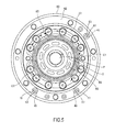
- FIG. 5 is a view along line V-V in FIG. 2 .
- the case-side flushing through hole 61 opens at a flange end face 62 of the case 60.
- An annular recess 63 is formed around the case-side flushing through hole 61.
- a seal ring is interposed between the annular recess 63 and the flange end face 72 of the base plate 70 to create a seal therebetween.
- the passage length of the flushing passage 47 is arbitrarily set and is configured such that the flow amount of hydraulic oil that is extracted from one of the first and second motor passages 41 and 42 to the flushing passage 47 is appropriately obtained.
- an outlet 47A of the flushing passage 47 opens at an inner wall surface of the case side part 60A.
- the outlet 47A is positioned near the case bottom part 60B, and opens facing an outer peripheral surface 7A of the swash plate 7.
- the outlet 47A is oriented toward a swash plate rear space 64 that is defined between the swash plate 7 and the case bottom part 60B, such that hydraulic oil that flows out from the outlet 47A is led to the swash plate rear space 64.
- hydraulic oil that flows from the outlet 47A into the casing chamber 58 flows along the swash plate 7, an inner wall surface of the case bottom part 60B, and the bearing 17, and thus the case bottom part 60B and the bearing 17 are effectively cooled.
- the flushing passage 47 can be formed so as to pass near the bearing 17 and the oil seal 37 within the case bottom part 60B, so that heat of the case bottom part 60B is absorbed by the hydraulic oil flowing through the flushing passage 47 to cool the bearing 17 and the oil seal 37, which can easily overheat.
- the casing chamber 58 is partitioned into a swash plate housing chamber 58A and a brake front chamber 58B by the brake discs 21 and the friction plates 22 of the parking brake 20.
- the outlet 47A of the flushing passage 47 opens into the swash plate housing chamber 58A that houses the swash plate 7. Hydraulic oil that flows in from the outlet 47A is led to the swash plate rear space 64.
- hydraulic oil that flows into the casing chamber 58 is returned to the tank via the in-motor drain passage 49 and the out-of-motor drain passage.
- the in-motor drain passage 49 is defined by first and second drain through holes 67 and 68 (refer to FIG. 5 ) formed in the case side part 60A.
- the first and second drain through holes 67 and 68 open at the inner wall surface of the case side part 60A as drain inlets that allow hydraulic oil to flow out from the casing chamber 58 to the in-motor drain passage 49.
- An inlet 67A which is an opening end of the first drain through hole 67, opens into the swash plate housing chamber 58A that houses the swash plate 7 and is formed at a position opposing the outlet 47A with the swash plate 7 therebetween.
- An opening end (not illustrated) of the second drain through hole 68 is also similarly formed at a position opposing the outlet 47A with the swash plate 7 therebetween.
- the first and second drain through holes 67 and 68 that define the in-motor drain passage 49 open at the flange end surface 62 of the case 60.
- Annular recesses 77 and 78 are respectively formed around the first and second drain through holes 67 and 68.
- Seal rings are respectively interposed between the annular recesses 77 and 78 and the flange end surface 72 of the base plate 70 to create a seal therebetween.
- each of through holes 73 and 74 that connect to the first and second drain through holes 67 and 68 opens at the flange end face 72 of the base plate 70.
- Drain grooves 75 and 76 also open at the flange end face 72 of the base plate 70.
- the drain grooves 75 and 76 extend in a circular arc so as to face the brake piston 27.
- a plurality of spring receiving recesses 80 in which the brake spring 26 is seated are formed on the inner walls of the drain grooves 75 and 76.
- FIG. 6 is a cross-section view along line VI-VI in FIG. 4 .
- the through hole 73 is in communication with the drain groove 75 via through holes 81 and 82.
- the through hole 82 is formed coaxially with the through hole 79 that is connected to the speed switching valve 43.
- FIG. 7 is a cross-section view along line VII-VII in FIG. 4 . As shown in FIG. 7 , the through hole 74 is in communication with the drain groove 76 via through holes 83 and 84.
- a through hole 85 that defines the in-motor drain passage 49 opens at the drain groove 76.
- One end of the through hole 85 opens at an outer wall surface of the base plate 70.
- the out-of-motor drain passage is connected to the one end of the through hole 85.
- hydraulic oil in the casing chamber 58 flows out through the in-motor drain passage 49.
- the in-motor drain passage 49 two hydraulic oil flows E1 and E2 are created from the case 60 across the base plate 70 by the first and second drain through holes 67 and 68, and thus a sufficient flow path cross-section area for the hydraulic oil that flows out from the casing chamber 58 is secured. Thereby, pressure increases in the casing chamber 58 are suppressed and the operation of the parking brake 20 is maintained.
- the constitution of the in-motor drain passage 49 is not limited thereto, and the in-motor drain passage 49 can be constituted to create three or more hydraulic oil flows by increasing the number of drain through holes.
- the piston motor 1 includes the motor mechanism 40 that rotates by hydraulic liquid that is supplied/discharged from a hydraulic liquid pressure source through one of the first motor passage 41 and the second motor passage 42.
- the piston motor 1 also includes the casing 59 that defines the casing chamber 58 which accommodates the motor mechanism 40, and the flushing passage 47 that is in communication with the casing chamber 58 and extracts a portion of hydraulic liquid from a low pressure side among the first motor passage 41 and the second motor passage 42 and leads it to the casing chamber 58 (refer to FIGS. 1 to 7 ).
- the motor mechanism 40 includes the swash plate 7 provided within the casing chamber 58, the plurality of pistons 6 that move back and forth following the swash plate 7 by hydraulic liquid pressure, the cylinder block 3 that rotates relative to the swash plate 7 by the back-and-forth motion of the pistons 6, and the output shaft 2 that outputs the rotation of the cylinder block 3.
- the casing 59 includes the base plate 70 in which the first motor passage 41 and the second motor passage 42 are provided, and the case 60 that supports the output shaft 2 and defines the casing chamber 58 together with the base plate 70.
- the flushing passage 47 is defined by the base-side flushing through hole 71 that is formed in the base plate 70 and the case-side flushing through hole 61 that is formed in the case 60 and is in communication with the base-side flushing through hole 71 (refer to FIGS. 1 to 5 ).
- the flushing passage 47 extends across the base plate 70 and the case 60, and enables hydraulic liquid that has flowed separately from the first and second motor passages 41 and 42 to flow into a back part of the casing chamber 58 (near the case bottom part 60B).
- the case 60 is sufficiently cooled in the case that an area of the case 60 (the case bottom part 60B) that is separated from the base plate 70 is heated by the reduction gear.
- the piston motor 1 includes the brake discs 21 that rotate together with the cylinder block 3, and the drain passage 39 that discharges hydraulic liquid of the casing chamber 58.
- the swash plate housing chamber 58A which houses the swash plate 7 and the brake front chamber 58B that is partitioned from the swash plate housing chamber 58A by the brake discs 21 are defined in the casing chamber 58.
- the outlet 47A of the flushing passage 47 and the inlet 67A of the drain passage 39 each open into the swash plate housing chamber 58A (refer to FIGS. 1 to 5 ).
- hydraulic liquid in the casing chamber 58 that heads from the outlet 47A of the flushing passage 47 toward the inlet 67A of the drain passage 39 passes through the swash plate housing chamber 58A which houses the swash plate 7 and does not cross the brake discs 21. Therefore, resistance on the hydraulic liquid by the rotating brake discs 21 is reduced, and the flow amount of hydraulic liquid that circulates through the casing chamber 58 is sufficient.
- the drain passage 39 is defined by the plurality of drain through holes 67 and 68 that open into the casing chamber 58 (refer to FIGS. 1 to 5 ).
- the plurality of hydraulic liquid flows E1 and E2 are created by the plurality of drain through holes 67 and 68, and thus a sufficient flow path cross-section area for the hydraulic liquid that flows out from the casing chamber 58 is secured.
- pressure increases in the casing chamber 58 are suppressed and the operation of the brake mechanism 25 (the parking brake 20) which imparts a frictional force on the brake discs 21 is maintained.
Landscapes
- Engineering & Computer Science (AREA)
- Mechanical Engineering (AREA)
- General Engineering & Computer Science (AREA)
- Chemical & Material Sciences (AREA)
- Combustion & Propulsion (AREA)
- Hydraulic Motors (AREA)
Applications Claiming Priority (2)
| Application Number | Priority Date | Filing Date | Title |
|---|---|---|---|
| JP2012036218A JP5891064B2 (ja) | 2012-02-22 | 2012-02-22 | 液圧モータ |
| PCT/JP2013/053497 WO2013125432A1 (ja) | 2012-02-22 | 2013-02-14 | 液圧モータ |
Publications (3)
| Publication Number | Publication Date |
|---|---|
| EP2806154A1 true EP2806154A1 (de) | 2014-11-26 |
| EP2806154A4 EP2806154A4 (de) | 2015-12-02 |
| EP2806154B1 EP2806154B1 (de) | 2019-12-04 |
Family
ID=49005619
Family Applications (1)
| Application Number | Title | Priority Date | Filing Date |
|---|---|---|---|
| EP13752104.3A Active EP2806154B1 (de) | 2012-02-22 | 2013-02-14 | Hydraulikmotor |
Country Status (6)
| Country | Link |
|---|---|
| US (1) | US10233900B2 (de) |
| EP (1) | EP2806154B1 (de) |
| JP (1) | JP5891064B2 (de) |
| KR (1) | KR101599174B1 (de) |
| CN (1) | CN104053901B (de) |
| WO (1) | WO2013125432A1 (de) |
Cited By (1)
| Publication number | Priority date | Publication date | Assignee | Title |
|---|---|---|---|---|
| WO2021123549A1 (fr) * | 2019-12-20 | 2021-06-24 | Poclain Hydraulics Industrie | Machine hydraulique comprenant un organe de défreinage |
Families Citing this family (8)
| Publication number | Priority date | Publication date | Assignee | Title |
|---|---|---|---|---|
| JP2016183621A (ja) * | 2015-03-26 | 2016-10-20 | Kyb株式会社 | 液圧モータ、そのブレーキ装置及びブレーキ装置の製造方法 |
| CN106050819A (zh) * | 2016-07-29 | 2016-10-26 | 柳州柳工挖掘机有限公司 | 工程机械行走马达壳体冲洗油路 |
| JP7049222B2 (ja) * | 2018-09-10 | 2022-04-06 | Kyb株式会社 | ブレーキシステム及びこれを備える液圧モータ |
| JP7153539B2 (ja) * | 2018-11-26 | 2022-10-14 | Kyb株式会社 | 流体圧駆動装置 |
| JP7281918B2 (ja) * | 2019-02-18 | 2023-05-26 | ナブテスコ株式会社 | 油圧モータ |
| CN110159618A (zh) * | 2019-06-28 | 2019-08-23 | 无锡市钻通工程机械有限公司 | 一种液压闭式冲洗回路 |
| CN115711159A (zh) * | 2022-11-30 | 2023-02-24 | 杭州力龙液压有限公司 | 回转体结构、柱塞马达以及作业机械 |
| US12601332B2 (en) * | 2023-07-07 | 2026-04-14 | Robert Bosch Gmbh | Integrated electro-hydraulic unit |
Family Cites Families (23)
| Publication number | Priority date | Publication date | Assignee | Title |
|---|---|---|---|---|
| US3089426A (en) * | 1958-09-17 | 1963-05-14 | New York Air Brake Co | Engine |
| US2961829A (en) * | 1959-10-15 | 1960-11-29 | New York Air Brake Co | Hydraulic transmission |
| US3181477A (en) * | 1961-09-14 | 1965-05-04 | Sperry Rand Corp | Power transmission |
| JP2557283Y2 (ja) | 1990-06-21 | 1997-12-10 | カヤバ工業株式会社 | 二速油圧モータ |
| US5419130A (en) | 1991-08-28 | 1995-05-30 | Hydromatik Gmbh | Hydrostatic machine with drain oil discharge |
| DE4128615C1 (de) * | 1991-08-28 | 1993-01-14 | Hydromatik Gmbh, 7915 Elchingen, De | |
| DE4303380A1 (de) * | 1993-02-05 | 1994-08-11 | Sachsenhydraulik Gmbh | Hydrostatische Kolbenmaschine |
| JPH109118A (ja) * | 1996-06-27 | 1998-01-13 | Kubota Corp | 減速機付油圧モータ |
| JP2001020847A (ja) * | 1999-07-08 | 2001-01-23 | Teijin Seiki Co Ltd | 流体モータの制動装置 |
| JP4577969B2 (ja) | 2000-09-26 | 2010-11-10 | 三輪精機株式会社 | 油圧モータ |
| FR2820186B1 (fr) * | 2001-01-31 | 2004-03-12 | Poclain Hydraulics Ind | Dispositif d'echange pour un circuit ferme |
| US20040000142A1 (en) * | 2002-06-27 | 2004-01-01 | Hirotaka Nunomura | High-pressure and low-pressure selecting valve and swash-plate type hydraulic motor system |
| JP3911211B2 (ja) | 2002-07-29 | 2007-05-09 | カヤバ工業株式会社 | 液圧モータ |
| JP2004125092A (ja) * | 2002-10-03 | 2004-04-22 | Hitachi Constr Mach Co Ltd | 油圧モータ用減速機の潤滑装置 |
| US20040187491A1 (en) * | 2003-03-26 | 2004-09-30 | Whitaker James S. | Pump with hot oil shuttle valve |
| EP1712788A1 (de) * | 2004-01-05 | 2006-10-18 | Hitachi Construction Machinery Co., Ltd. | Geneigte drehsteuervorrichtung einer hydraulikpumpe mit variabler verdrängung |
| JP2006161453A (ja) | 2004-12-08 | 2006-06-22 | Chugoku Electric Power Co Inc:The | 瓦棒葺き屋根の改修工法 |
| CN101514670A (zh) * | 2008-02-21 | 2009-08-26 | 白华平 | 液压泵式发动机及其制造方法 |
| JP4970357B2 (ja) | 2008-06-11 | 2012-07-04 | 株式会社クボタ | 油圧駆動式モータ装置 |
| JP5087580B2 (ja) * | 2009-03-30 | 2012-12-05 | 住友建機株式会社 | 建設機械の油圧モータ |
| JP5571350B2 (ja) | 2009-10-19 | 2014-08-13 | カヤバ工業株式会社 | 液圧モータ駆動装置 |
| CN201560890U (zh) * | 2009-11-05 | 2010-08-25 | 昆山金发液压机械有限公司 | 平面配油曲轴无连杆液压马达 |
| JP4540750B1 (ja) * | 2010-06-01 | 2010-09-08 | 株式会社小坂研究所 | サブマージドポンプ駆動用オイルモータの冷却機構 |
-
2012
- 2012-02-22 JP JP2012036218A patent/JP5891064B2/ja active Active
-
2013
- 2013-02-14 EP EP13752104.3A patent/EP2806154B1/de active Active
- 2013-02-14 CN CN201380005809.7A patent/CN104053901B/zh active Active
- 2013-02-14 US US14/372,942 patent/US10233900B2/en active Active
- 2013-02-14 KR KR1020147021141A patent/KR101599174B1/ko not_active Expired - Fee Related
- 2013-02-14 WO PCT/JP2013/053497 patent/WO2013125432A1/ja not_active Ceased
Cited By (2)
| Publication number | Priority date | Publication date | Assignee | Title |
|---|---|---|---|---|
| WO2021123549A1 (fr) * | 2019-12-20 | 2021-06-24 | Poclain Hydraulics Industrie | Machine hydraulique comprenant un organe de défreinage |
| FR3105309A1 (fr) * | 2019-12-20 | 2021-06-25 | Poclain Hydraulics Industrie | Machine hydraulique comprenant un organe de défreinage |
Also Published As
| Publication number | Publication date |
|---|---|
| KR20140105865A (ko) | 2014-09-02 |
| EP2806154B1 (de) | 2019-12-04 |
| JP2013170536A (ja) | 2013-09-02 |
| CN104053901B (zh) | 2016-04-20 |
| US10233900B2 (en) | 2019-03-19 |
| US20150000512A1 (en) | 2015-01-01 |
| EP2806154A4 (de) | 2015-12-02 |
| WO2013125432A1 (ja) | 2013-08-29 |
| CN104053901A (zh) | 2014-09-17 |
| KR101599174B1 (ko) | 2016-03-02 |
| JP5891064B2 (ja) | 2016-03-22 |
Similar Documents
| Publication | Publication Date | Title |
|---|---|---|
| EP2806154B1 (de) | Hydraulikmotor | |
| US9574543B2 (en) | Hydraulic motor | |
| US6988580B2 (en) | Pump unit and working vehicle | |
| US9353813B2 (en) | Wet brake device | |
| US7353650B2 (en) | Axle driving apparatus | |
| JPH109385A (ja) | 車軸駆動装置の中立復帰機構 | |
| US11274682B2 (en) | Hydraulic driving apparatus | |
| JP4532250B2 (ja) | 減速機付き油圧モータ | |
| JP6114089B2 (ja) | 対向式斜板型ピストンポンプ・モータ | |
| WO2009096100A1 (ja) | ブレーキ装置 | |
| JP2568922B2 (ja) | 油圧ニユットの分配環 | |
| JP4516878B2 (ja) | アクスル装置 | |
| JP2002013636A (ja) | 流体圧伝動装置 | |
| JPH11223175A (ja) | プランジャ式油圧ユニット | |
| JP2009216125A (ja) | 動力断続機 | |
| JP4832178B2 (ja) | 可変容量型斜板式液圧回転機 | |
| JP3462978B2 (ja) | 斜板式2連ピストンポンプにおける潤滑構造 | |
| GB2237621A (en) | Hydrostatic transmission | |
| KR20000075949A (ko) | 차축 구동 시스템 |
Legal Events
| Date | Code | Title | Description |
|---|---|---|---|
| PUAI | Public reference made under article 153(3) epc to a published international application that has entered the european phase |
Free format text: ORIGINAL CODE: 0009012 |
|
| 17P | Request for examination filed |
Effective date: 20140722 |
|
| AK | Designated contracting states |
Kind code of ref document: A1 Designated state(s): AL AT BE BG CH CY CZ DE DK EE ES FI FR GB GR HR HU IE IS IT LI LT LU LV MC MK MT NL NO PL PT RO RS SE SI SK SM TR |
|
| DAX | Request for extension of the european patent (deleted) | ||
| RA4 | Supplementary search report drawn up and despatched (corrected) |
Effective date: 20151104 |
|
| RIC1 | Information provided on ipc code assigned before grant |
Ipc: F03C 1/253 20060101AFI20151029BHEP |
|
| RAP1 | Party data changed (applicant data changed or rights of an application transferred) |
Owner name: KYB CORPORATION |
|
| GRAP | Despatch of communication of intention to grant a patent |
Free format text: ORIGINAL CODE: EPIDOSNIGR1 |
|
| STAA | Information on the status of an ep patent application or granted ep patent |
Free format text: STATUS: GRANT OF PATENT IS INTENDED |
|
| INTG | Intention to grant announced |
Effective date: 20190801 |
|
| GRAS | Grant fee paid |
Free format text: ORIGINAL CODE: EPIDOSNIGR3 |
|
| GRAA | (expected) grant |
Free format text: ORIGINAL CODE: 0009210 |
|
| STAA | Information on the status of an ep patent application or granted ep patent |
Free format text: STATUS: THE PATENT HAS BEEN GRANTED |
|
| RIN1 | Information on inventor provided before grant (corrected) |
Inventor name: KAWABATA, KAORI |
|
| AK | Designated contracting states |
Kind code of ref document: B1 Designated state(s): AL AT BE BG CH CY CZ DE DK EE ES FI FR GB GR HR HU IE IS IT LI LT LU LV MC MK MT NL NO PL PT RO RS SE SI SK SM TR |
|
| REG | Reference to a national code |
Ref country code: GB Ref legal event code: FG4D |
|
| REG | Reference to a national code |
Ref country code: CH Ref legal event code: EP |
|
| REG | Reference to a national code |
Ref country code: AT Ref legal event code: REF Ref document number: 1209725 Country of ref document: AT Kind code of ref document: T Effective date: 20191215 |
|
| REG | Reference to a national code |
Ref country code: DE Ref legal event code: R096 Ref document number: 602013063611 Country of ref document: DE |
|
| REG | Reference to a national code |
Ref country code: IE Ref legal event code: FG4D |
|
| REG | Reference to a national code |
Ref country code: NL Ref legal event code: MP Effective date: 20191204 |
|
| REG | Reference to a national code |
Ref country code: LT Ref legal event code: MG4D |
|
| PG25 | Lapsed in a contracting state [announced via postgrant information from national office to epo] |
Ref country code: FI Free format text: LAPSE BECAUSE OF FAILURE TO SUBMIT A TRANSLATION OF THE DESCRIPTION OR TO PAY THE FEE WITHIN THE PRESCRIBED TIME-LIMIT Effective date: 20191204 Ref country code: BG Free format text: LAPSE BECAUSE OF FAILURE TO SUBMIT A TRANSLATION OF THE DESCRIPTION OR TO PAY THE FEE WITHIN THE PRESCRIBED TIME-LIMIT Effective date: 20200304 Ref country code: NO Free format text: LAPSE BECAUSE OF FAILURE TO SUBMIT A TRANSLATION OF THE DESCRIPTION OR TO PAY THE FEE WITHIN THE PRESCRIBED TIME-LIMIT Effective date: 20200304 Ref country code: GR Free format text: LAPSE BECAUSE OF FAILURE TO SUBMIT A TRANSLATION OF THE DESCRIPTION OR TO PAY THE FEE WITHIN THE PRESCRIBED TIME-LIMIT Effective date: 20200305 Ref country code: LT Free format text: LAPSE BECAUSE OF FAILURE TO SUBMIT A TRANSLATION OF THE DESCRIPTION OR TO PAY THE FEE WITHIN THE PRESCRIBED TIME-LIMIT Effective date: 20191204 Ref country code: ES Free format text: LAPSE BECAUSE OF FAILURE TO SUBMIT A TRANSLATION OF THE DESCRIPTION OR TO PAY THE FEE WITHIN THE PRESCRIBED TIME-LIMIT Effective date: 20191204 Ref country code: LV Free format text: LAPSE BECAUSE OF FAILURE TO SUBMIT A TRANSLATION OF THE DESCRIPTION OR TO PAY THE FEE WITHIN THE PRESCRIBED TIME-LIMIT Effective date: 20191204 Ref country code: SE Free format text: LAPSE BECAUSE OF FAILURE TO SUBMIT A TRANSLATION OF THE DESCRIPTION OR TO PAY THE FEE WITHIN THE PRESCRIBED TIME-LIMIT Effective date: 20191204 |
|
| PG25 | Lapsed in a contracting state [announced via postgrant information from national office to epo] |
Ref country code: RS Free format text: LAPSE BECAUSE OF FAILURE TO SUBMIT A TRANSLATION OF THE DESCRIPTION OR TO PAY THE FEE WITHIN THE PRESCRIBED TIME-LIMIT Effective date: 20191204 Ref country code: HR Free format text: LAPSE BECAUSE OF FAILURE TO SUBMIT A TRANSLATION OF THE DESCRIPTION OR TO PAY THE FEE WITHIN THE PRESCRIBED TIME-LIMIT Effective date: 20191204 |
|
| PG25 | Lapsed in a contracting state [announced via postgrant information from national office to epo] |
Ref country code: AL Free format text: LAPSE BECAUSE OF FAILURE TO SUBMIT A TRANSLATION OF THE DESCRIPTION OR TO PAY THE FEE WITHIN THE PRESCRIBED TIME-LIMIT Effective date: 20191204 |
|
| PG25 | Lapsed in a contracting state [announced via postgrant information from national office to epo] |
Ref country code: NL Free format text: LAPSE BECAUSE OF FAILURE TO SUBMIT A TRANSLATION OF THE DESCRIPTION OR TO PAY THE FEE WITHIN THE PRESCRIBED TIME-LIMIT Effective date: 20191204 Ref country code: RO Free format text: LAPSE BECAUSE OF FAILURE TO SUBMIT A TRANSLATION OF THE DESCRIPTION OR TO PAY THE FEE WITHIN THE PRESCRIBED TIME-LIMIT Effective date: 20191204 Ref country code: CZ Free format text: LAPSE BECAUSE OF FAILURE TO SUBMIT A TRANSLATION OF THE DESCRIPTION OR TO PAY THE FEE WITHIN THE PRESCRIBED TIME-LIMIT Effective date: 20191204 Ref country code: PT Free format text: LAPSE BECAUSE OF FAILURE TO SUBMIT A TRANSLATION OF THE DESCRIPTION OR TO PAY THE FEE WITHIN THE PRESCRIBED TIME-LIMIT Effective date: 20200429 Ref country code: EE Free format text: LAPSE BECAUSE OF FAILURE TO SUBMIT A TRANSLATION OF THE DESCRIPTION OR TO PAY THE FEE WITHIN THE PRESCRIBED TIME-LIMIT Effective date: 20191204 |
|
| PG25 | Lapsed in a contracting state [announced via postgrant information from national office to epo] |
Ref country code: IS Free format text: LAPSE BECAUSE OF FAILURE TO SUBMIT A TRANSLATION OF THE DESCRIPTION OR TO PAY THE FEE WITHIN THE PRESCRIBED TIME-LIMIT Effective date: 20200404 Ref country code: SK Free format text: LAPSE BECAUSE OF FAILURE TO SUBMIT A TRANSLATION OF THE DESCRIPTION OR TO PAY THE FEE WITHIN THE PRESCRIBED TIME-LIMIT Effective date: 20191204 Ref country code: SM Free format text: LAPSE BECAUSE OF FAILURE TO SUBMIT A TRANSLATION OF THE DESCRIPTION OR TO PAY THE FEE WITHIN THE PRESCRIBED TIME-LIMIT Effective date: 20191204 |
|
| REG | Reference to a national code |
Ref country code: DE Ref legal event code: R097 Ref document number: 602013063611 Country of ref document: DE |
|
| REG | Reference to a national code |
Ref country code: AT Ref legal event code: MK05 Ref document number: 1209725 Country of ref document: AT Kind code of ref document: T Effective date: 20191204 |
|
| REG | Reference to a national code |
Ref country code: CH Ref legal event code: PL |
|
| PLBE | No opposition filed within time limit |
Free format text: ORIGINAL CODE: 0009261 |
|
| STAA | Information on the status of an ep patent application or granted ep patent |
Free format text: STATUS: NO OPPOSITION FILED WITHIN TIME LIMIT |
|
| REG | Reference to a national code |
Ref country code: BE Ref legal event code: MM Effective date: 20200229 |
|
| PG25 | Lapsed in a contracting state [announced via postgrant information from national office to epo] |
Ref country code: LU Free format text: LAPSE BECAUSE OF NON-PAYMENT OF DUE FEES Effective date: 20200214 Ref country code: MC Free format text: LAPSE BECAUSE OF FAILURE TO SUBMIT A TRANSLATION OF THE DESCRIPTION OR TO PAY THE FEE WITHIN THE PRESCRIBED TIME-LIMIT Effective date: 20191204 Ref country code: DK Free format text: LAPSE BECAUSE OF FAILURE TO SUBMIT A TRANSLATION OF THE DESCRIPTION OR TO PAY THE FEE WITHIN THE PRESCRIBED TIME-LIMIT Effective date: 20191204 |
|
| 26N | No opposition filed |
Effective date: 20200907 |
|
| PG25 | Lapsed in a contracting state [announced via postgrant information from national office to epo] |
Ref country code: PL Free format text: LAPSE BECAUSE OF FAILURE TO SUBMIT A TRANSLATION OF THE DESCRIPTION OR TO PAY THE FEE WITHIN THE PRESCRIBED TIME-LIMIT Effective date: 20191204 Ref country code: AT Free format text: LAPSE BECAUSE OF FAILURE TO SUBMIT A TRANSLATION OF THE DESCRIPTION OR TO PAY THE FEE WITHIN THE PRESCRIBED TIME-LIMIT Effective date: 20191204 Ref country code: LI Free format text: LAPSE BECAUSE OF NON-PAYMENT OF DUE FEES Effective date: 20200229 Ref country code: SI Free format text: LAPSE BECAUSE OF FAILURE TO SUBMIT A TRANSLATION OF THE DESCRIPTION OR TO PAY THE FEE WITHIN THE PRESCRIBED TIME-LIMIT Effective date: 20191204 Ref country code: CH Free format text: LAPSE BECAUSE OF NON-PAYMENT OF DUE FEES Effective date: 20200229 |
|
| PG25 | Lapsed in a contracting state [announced via postgrant information from national office to epo] |
Ref country code: IE Free format text: LAPSE BECAUSE OF NON-PAYMENT OF DUE FEES Effective date: 20200214 Ref country code: FR Free format text: LAPSE BECAUSE OF NON-PAYMENT OF DUE FEES Effective date: 20200229 Ref country code: IT Free format text: LAPSE BECAUSE OF FAILURE TO SUBMIT A TRANSLATION OF THE DESCRIPTION OR TO PAY THE FEE WITHIN THE PRESCRIBED TIME-LIMIT Effective date: 20191204 |
|
| PG25 | Lapsed in a contracting state [announced via postgrant information from national office to epo] |
Ref country code: BE Free format text: LAPSE BECAUSE OF NON-PAYMENT OF DUE FEES Effective date: 20200229 |
|
| GBPC | Gb: european patent ceased through non-payment of renewal fee |
Effective date: 20200304 |
|
| PG25 | Lapsed in a contracting state [announced via postgrant information from national office to epo] |
Ref country code: GB Free format text: LAPSE BECAUSE OF NON-PAYMENT OF DUE FEES Effective date: 20200304 |
|
| PG25 | Lapsed in a contracting state [announced via postgrant information from national office to epo] |
Ref country code: TR Free format text: LAPSE BECAUSE OF FAILURE TO SUBMIT A TRANSLATION OF THE DESCRIPTION OR TO PAY THE FEE WITHIN THE PRESCRIBED TIME-LIMIT Effective date: 20191204 Ref country code: MT Free format text: LAPSE BECAUSE OF FAILURE TO SUBMIT A TRANSLATION OF THE DESCRIPTION OR TO PAY THE FEE WITHIN THE PRESCRIBED TIME-LIMIT Effective date: 20191204 Ref country code: CY Free format text: LAPSE BECAUSE OF FAILURE TO SUBMIT A TRANSLATION OF THE DESCRIPTION OR TO PAY THE FEE WITHIN THE PRESCRIBED TIME-LIMIT Effective date: 20191204 |
|
| PG25 | Lapsed in a contracting state [announced via postgrant information from national office to epo] |
Ref country code: MK Free format text: LAPSE BECAUSE OF FAILURE TO SUBMIT A TRANSLATION OF THE DESCRIPTION OR TO PAY THE FEE WITHIN THE PRESCRIBED TIME-LIMIT Effective date: 20191204 |
|
| PGFP | Annual fee paid to national office [announced via postgrant information from national office to epo] |
Ref country code: DE Payment date: 20260218 Year of fee payment: 14 |